TriGem 440EX Micro ATX Motherboard (Como3) Table of Contents I. Introduction 1. Generation Description ---------------------------------------------------------- 2 2. Function Block Diagram -------------------------------------------------------- 4 II. System Overview 1. Major Units ------------------------------------------------------------------------ 5 2. Upgradeability ---------------------------------------------------------------------- 5 2-1. Processor ----------------------------------------------------------------------- 5 2-2. Memory ------------------------------------------------------------------------- 6 2-3. Expansion Slot ----------------------------------------------------------------- 6 2-4. I/O Interface -------------------------------------------------------------------- 7 2-5. Manufacturing Options --------------------------------------------------------- 7 III. Jumper & Connector Description 1. Motherboard Jumper Setting ------------------------------------------------------- 8 1-1. Selection for Pentium II processor CPU Clock ------------------------ 8 1-2. Other function control ------------------------------------------------------- 8 2. Motherboard Header Connector -------------------------------------------------- 9 3. Motherboard Internal I/O Connector --------------------------------------------- 13
Transcript
TriGem 440EX Micro ATXMotherboard (Como3)
Table of Contents
I. Introduction
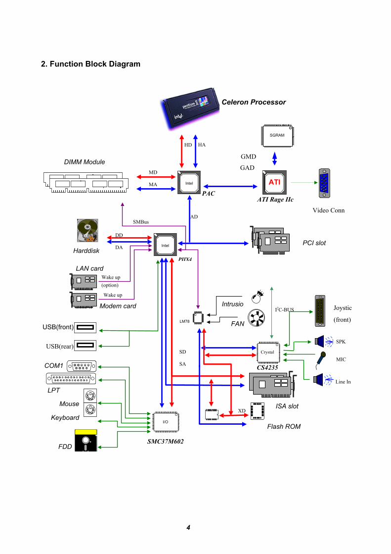
1. Generation Description ---------------------------------------------------------- 22. Function Block Diagram -------------------------------------------------------- 4
II. System Overview
1. Major Units ------------------------------------------------------------------------ 52. Upgradeability ---------------------------------------------------------------------- 5
1. Motherboard Jumper Setting ------------------------------------------------------- 81-1. Selection for Pentium II processor CPU Clock ------------------------ 81-2. Other function control ------------------------------------------------------- 8
The Como3 Micro ATX motherboard delivers the excellent functionality, the cost effective performance.This board is designed to support Intel Pentium II processor with MMX media enhancement technology, and toprovide the high performance, component level interconnect targeted 3D graphical display application (A.G.P)and Intel’s OPSD manageability for the office environment. Special controller is built in the board to supportACPI function fully, however it will be the optional feature according to the market segment.
Small PCB size in the Micro ATX form factor• 243mm * 223mm * 1.6t (4 Layers)• Cost-effective PCB size
Intel Celeron processor 266/300MHz• Single Edge Contact Cartridge design not include a dedicated L2 cache• Slot 1 connector
2 DIMM banks for EDO/SDRAM module• 3.3V EDO/SDRAM supported (168pin unbuffered DIMM)• Supports up to 256MB (128MB * 2 banks)
High performance targeted 3D graphical display.• Built-in AGP graphic controller (ATI RAGE IIC)• SGRAM 2Mbyte Video Memory on Board(32bit operation)
Intel 440EX core and FDC37M602 Super I/O controller• High performance core chip with two BGA package
Built-in high performance 3D ISA audio CODEC• Built-in ISA audio CODEC (CS4235B)
Support Intel’s OPSD manageability level-3• Remote wake up solution : LAN(option) and Modem• FAN control logic : CPU Fan, system Fan(option)• System chassis intrusion(option)• System voltage and temperature management(option)
Management Levels
Level-1 ECC on memory, DMTF compliant softwareLevel-2 Alert generation in system temperature, voltage, FAN speed, chassis intrusionLevel-3 Remote wake up over LAN, service bootLevel-4 Resume to task, improved power management, OS independent management
FAN off
2 ISA, 2 PCI slots and 1 shared slot• Master operating function on all PCI slot
Variable I/O interface• Two USB port (One in front panel, the other in rear port) : Keyboard, Mouse, CCD Camera• Two PS/2 port : Keyboard, Mouse• Two Serial port : COM1 port and optional COM2 port by Header Connector• One Parallel port : DB25, LPT1• One Audio/Joystick port : 1 Speaker, 1MIC_IN, 1 LINE_IN, 1 MIDI/Joystick port(front panel)• One FDD connector : 34-pin, boxing type
3
• Two E-IDE connector : 40-pin, boxing type, primary and secondary interface• One power connector : 20-pin, standard ATX power connector module• One power connector : 6-pin, 1394 power connector(option)• One AMC connector : 38-pin, ATI AMC interface
FDC37M602 ITE Super I/O Chipset PQFP-100pin AICS9148-08 ICS System Clock Chip SSOP-48pinSC1164 SEMTECH DC to DC Converter SOP-24pinCS4235 Crystal ISA Sound Controller QFP-100pin JQ(Rev.C)3D RAGE IIC ATI AGP Graphic Controller BGA-256pin 215R2BUA21LM79CCVF NSC Management Extension Hardware PQFP-44pin J
For more information, refer to the data sheet.
2. Upgradeability
This section describes the major specification of user upgradeable part. CPU, Memory, and Extension slot will provide the user to leverage the overall performance by adding or changing these part with other
higher.
CPU : CELERON processor-266/300MHzMemory : EDO, SDRAM (2 Banks, 16MB - 256MB)Expansion slot : 2 master PCI, 2 ISA, and 1 shared slot
2-1 Processor
This motherboard supports a single Celeron processor. The processor’s VID pin automatically programthe voltage regulator on the motherboard to the required processor voltage. The motherboard supportsprocessors that run internally at 266/300MHz.
Packing• Single Edge Contact ( S.E.C.) cartridge - processor core, second level cache, thermal plate..• Retention mechanism attached to the motherboard.
6
2-2. Memory
The memory controller, Intel 440EX support EDO module, and SDRAM module, up to two banks,however EDO and SDRAM module will be available with 168-pin unbuffered DIMM module and 3.3Vversion. The BIOS automatically detects memory type, size, and speed.
The motherboard supports the following memory features.• 168-pin DIMMs with gold-plated contacts• 66MHz SDRAM only• Non-ECC(64-bit) memory• 3.3 V Memory only• Single- or double-sided DIMMs in the following sizes
DRAM key position Voltage key position(buffered or unbuffered) (3.3V or 5V)
To function properly, SDRAM DIMMs must meet the Intel 4-clock, 66MHz unbuffered SDRAM specification for either 64-bit SDRAM.
2-3. Expansion Slot
This Micro ATX has two ISA expansion slots and two PCI expansion slot, but total three add-on cards could be available together due to one shared slot. Also all PCI slot can support the master device on it
with PnP function.
Interrupt and IDSEL assignment of PCI slotsInterrupt mappingPCI slot IDSEL
INTA INTB INTC INTDRemarks
CN12 (PCI-1) AD30 A B C DCN13 (PCI-2) AD29 B C D A
7
2-4. I/O Interface
This Micro ATX motherboard has one serial port, one parallel port, two PS/2 port for keyboard and mouse, and two USB port, Audio & MIDI/Joystick to upgrade the external peripheral devices, such as mouse, modem, printer, scanner, etc.
Mouse USB Parallel PCI PCI ISA ISAKeyboard COM1 Video SPK Line-In MIC
USB Joystick
2-5. Manufacturing Options.
This Micro ATX motherboard has the several manufacturing options according to the type of the motherboard. The following features are implemented based on the customer requirement.
• Hardware monitoring function : LM78/79 functionality• FAN control function : MIC29204 functionality• Power Supply FAN control : 6pin connector or 3pin connector
3. LED
3-1. Power LED
Normal State GreenSuspend State Green LED is blinking
Off State LED is off
3-2. HDD LED
Amber colored LED is on whenever HDD is being accessed
LED1(HDD LED : Amber)
CN1(LED board interface connector)
SW1(Power on/off switch with LED : Green)
8
III. Jumper and Connector Descriptions
1. Motherboard Jumper Setting
J11
J131-1. Selection for Processor CPU Clock (J13)
CPU Clock J13-1 J13-2 J13-3 J13-4233MHz ON OFF OFF ON266MHz OFF ON ON ON
*300MHz OFF ON OFF ON333MHz OFF OFF ON ON
1-2. Other function controlSwitch Functionality ON OFFJ13-5 CMOS RAM Clear CMOS RAM *NormalJ13-6 Password Disable *EnableJ13-7 CMOS Setup Disable *EnableJ13-8 FDD Write Protect Write Protect *Normal
Jumper Set to 1-2 Set to 2-3J11 Disable built-in AGP *Enable built-in AGP
* : Default Setting
9
2. Motherboard Header Connector
CN70 CN46
CN44CN43CN45
CN23
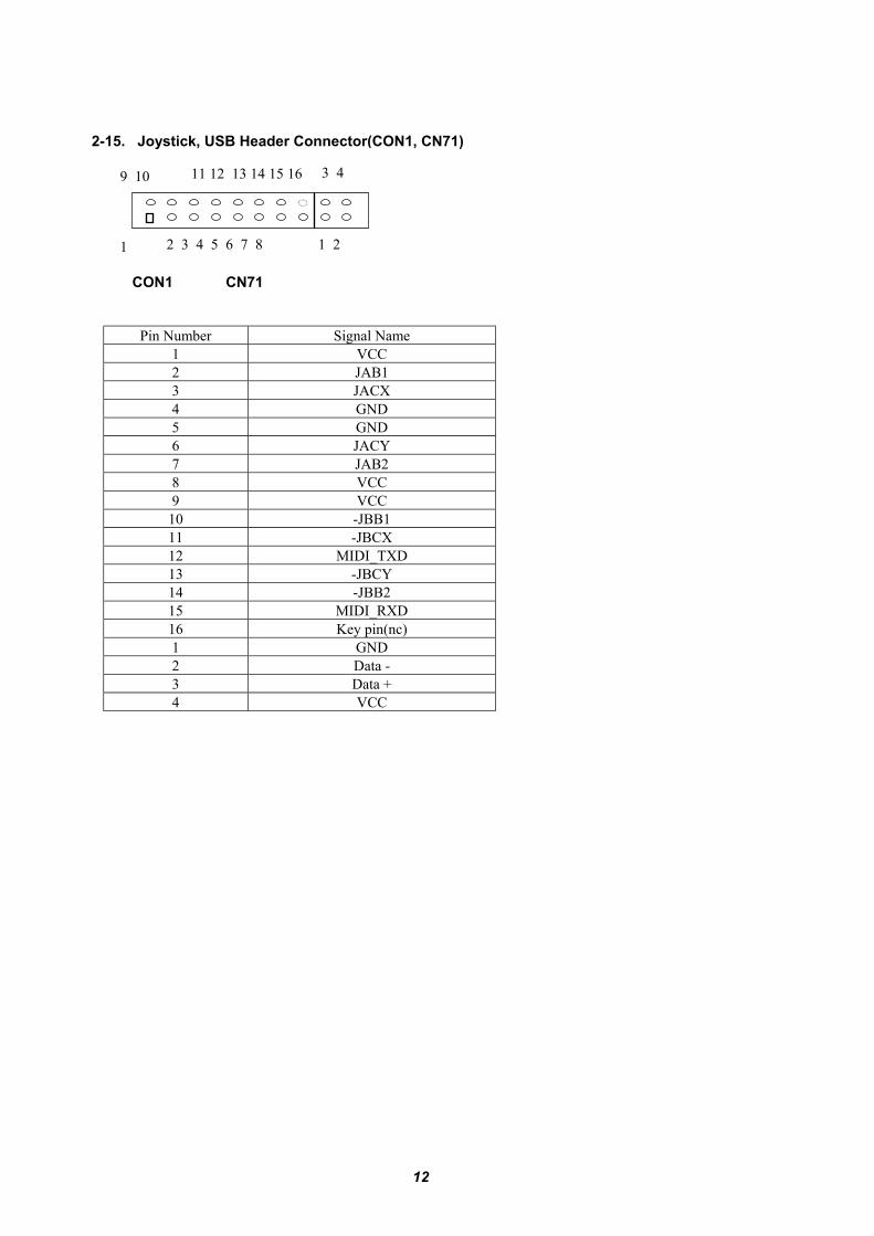
CON1,CN71
SPK1
CN56 CN50 CN53 CN54 CN51 CN49 CN48 CN52 CN8(CN55)
2-1. System FAN Connector(CN53:option)Pin Number Signal Name
1 Ground2 FANCNTL3 FANSEN1
2-2. CPU FAN Connector(CN54)Pin Number Signal Name
1 Ground2 FANCNTL3 FANSEN2
2-3. LAN Wake-up Connector(CN50:option)Pin Number Signal Name
1 +5VSB2 Ground3 LAN_WAKE
10
2-4. Modem Ring Wake-up Connector(CN51)Pin Number Signal Name
1 #RING_A or #RING_B2 Ground3 +5VSB
2-5. CD-ROM Sound Connector(CN43, CN44)Pin Number Signal Name(ATAPI,CN43) Signal Name(Mitsumi,CN44)