50
Version 1.00 Revision A Part Number 022543-106 January 2005 Trimble ® S6 Total Station Demonstration Guide

Version 1.00Revision A
Part Number 022543-106January 2005
Trimble® S6 Total StationDemonstration Guide

Contact InformationTrimble Geomatics and Engineering Division5475 Kellenburger RoadDayton, Ohio 45424-1099USA
800-538-7800 (toll free in USA)+1-937-233-8921 Phone+1-937-233-9004 Fax
www.trimble.com
Copyright and Trademarks© 2005, Trimble Navigation Limited. All rights reserved.
Trimble, the Globe & Triangle logo, Autolock, Geodimeter, and Tracklight are trademarks of Trimble Navigation Limited, registered in the United States Patent and Trademark Office and in other countries. MultiTrack, SurePoint, Trimble Geomatics Office, Trimble Survey Controller and MagDrive are trademarks of Trimble Navigation Limited. Survey Pro is a trademark of Tripod Data Systems Inc., a wholly owned subsidiary of Trimble Navigation Limited. The Bluetooth word mark and logos are owned by the Bluetooth SIG, Inc. and any use of such marks by Trimble Navigation Limited is under license. Microsoft, ActiveSync, and Windows are either registered trademarks or trademarks of Microsoft Corporation in the United States and/or other countries. All other trademarks are the property of their respective owners.
Release NoticeThis is the January 2005 release (Revision A) of the Trimble S6 Total Station Demonstration Guide, part number 022543-106. It applies to version 1.00 of the Trimble S6 Total Station.
1.1 Contents
Introduction . . . . . . . . . . . . . . . . . . . . . . . . . . . . . . . . . . . . . . . . . . . . 4The training data . . . . . . . . . . . . . . . . . . . . . . . . . . . . . . . . . . . . . 4Preparing for the demonstration . . . . . . . . . . . . . . . . . . . . . . . . . . . . . 5
Selecting a Site . . . . . . . . . . . . . . . . . . . . . . . . . . . . . . . . . . . . . . . . . . 5Overview Session: Features of the Trimble S6 Total Station. . . . . . . . . . . . . . . . . . . 6
Hardware features . . . . . . . . . . . . . . . . . . . . . . . . . . . . . . . . . . . . . 6Operating features. . . . . . . . . . . . . . . . . . . . . . . . . . . . . . . . . . . . 11MagDrive servo technology. . . . . . . . . . . . . . . . . . . . . . . . . . . . . . . 13MultiTrack technology . . . . . . . . . . . . . . . . . . . . . . . . . . . . . . . . . 15Robotic connection . . . . . . . . . . . . . . . . . . . . . . . . . . . . . . . . . . . 17Summary . . . . . . . . . . . . . . . . . . . . . . . . . . . . . . . . . . . . . . . . 18
Field Sessions . . . . . . . . . . . . . . . . . . . . . . . . . . . . . . . . . . . . . . . . . 19Session 1: Basic station setup, and topographic measurement . . . . . . . . . . . . . 19Session 2: Advanced station setup, and automated rounds . . . . . . . . . . . . . . . 26Session 3: Staking out points and lines . . . . . . . . . . . . . . . . . . . . . . . . . 32Session 4: Advanced topographic measurements . . . . . . . . . . . . . . . . . . . . 38Session 5: Stakeout roads . . . . . . . . . . . . . . . . . . . . . . . . . . . . . . . . 42Session 6: COGO and other features . . . . . . . . . . . . . . . . . . . . . . . . . . 46
Trimble S6 Total Station Demonstration Guide 3
Introduction – The t rain ing data
1.2 IntroductionWelcome to the Demonstration Guide for the Trimble® S6 Total Station using a Trimble CU running the Trimble Survey Controller™ software. This document provides a complete, easy-to-use guide of how to demonstrate the benefits and capabilities of this instrument.
The guide can be used for sales demonstrations, product introductions, or to form the basis of a complete training course. While providing a clear and simple overview of the complete instrument, the guide has also been structured to enable you to tailor a demonstration to your customer’s particular area of interest. It is not expected that a demonstration will cover all the points given in this guide. You should always identify your customer’s needs in advance. This will enable you to refer to the relevant sections of the demonstration guide to concentrate on the key features and benefits that are relevant for their applications and workflows.
This guide is also just that, a “guide”, which enables you to quickly get up to speed with the Trimble S6 total station. Once you have this solid base, you will naturally apply your own experience and knowledge when carrying out demonstrations.
Use this guide to describe and demonstrate:
• Key features and benefits of the instrument
• Hardware features and benefits of the instrument
• Basic operating features of the instrument
• How to perform a basic station establishment
• How to perform topographic measurements
• How to perform a resection and multiple rounds of observations
• How to use automated topographic measurement techniques
• How to stake out points
• How to stake out lines
• How to stake out roads
• Additional survey features, such as field calculations and file transfer
12.1 The training data
The training data is designed to provide one simple data set that enables the features of the Trimble S6 total station and Trimble Survey Controller software to be effectively demonstrated. The files that comprise the training data include:
• Survey Control.csv (CSV control coordinate file)
• Survey DTM.dtm (sample DTM)
• Demo road.job (sample template road design)
• Road XML (sample XML road design)
4 Trimble S6 Total Station Demonstration Guide
Selecting a Site – Prepar ing for the demonstrat ion
• Road and Building.dxf (background map DXF file)
• Building and Services.dxf (background map DXF file)
• Vegetation.dxf (background map DXF file)
• DTM.dxf (background map DXF file)
• Default.fal (Feature and Attribute library file)
The points in the Survey Control.csv file include:
12.2 Preparing for the demonstration
Before starting your demonstration, make sure that all your demonstration equipment is ready and in good condition. This includes:
• Charging the batteries
• Loading data to the data collector
• Checking that the instrument is properly collimated and adjusted. Demo units should be regularly taken to the dealer’s Service Center to keep them it good condition.
In addition, keep in mind where you will carry out the demonstration: Try to avoid noisy, distracting, or dangerous locations.
1.3 Selecting a SiteWhen you select a site:
1. Make sure the site has at least 40 m (90 ft) of flat, open space with good visibility.
2. Place two markers in the ground to use as point 1 and point 2 from the training data.
3. Ensure that point 1 is on one edge of the open space and that point 2 is on the opposite edge.
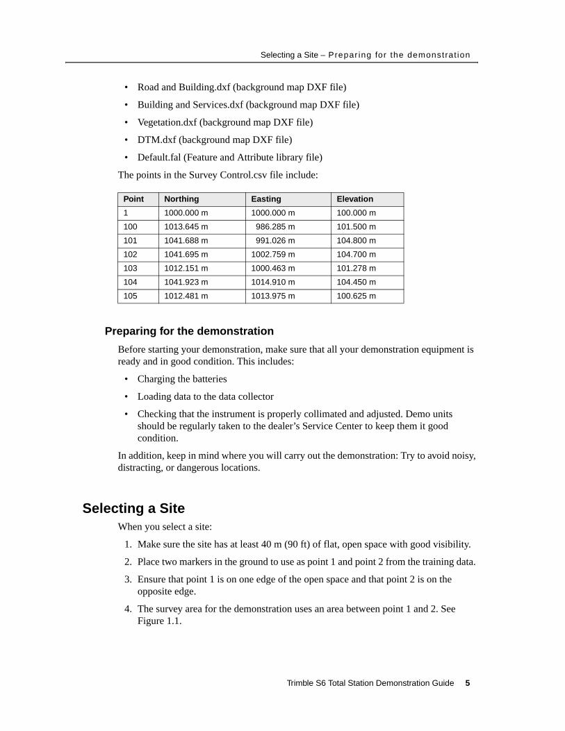
4. The survey area for the demonstration uses an area between point 1 and 2. See Figure 1.1.
Point Northing Easting Elevation
1 1000.000 m 1000.000 m 100.000 m
100 1013.645 m 986.285 m 101.500 m
101 1041.688 m 991.026 m 104.800 m
102 1041.695 m 1002.759 m 104.700 m
103 1012.151 m 1000.463 m 101.278 m
104 1041.923 m 1014.910 m 104.450 m
105 1012.481 m 1013.975 m 100.625 m
Trimble S6 Total Station Demonstration Guide 5
Overview Session: Features of the Trimble S6 Total Station – Hardware features
Figure 1.1 Demonstration survey area
1.1 Overview Session: Features of the Trimble S6 Total StationTo demonstrate the key features and benefits of the instrument, including:
• MagDrive™ servo technology – fast and accurate integrated angle and servo system
• SurePoint™ technology to protect accuracy
• MultiTrack™ technology to track prism targets and allow active tracking with the Target ID
• Trimble DR technology to provide fast, accurate, long range measurements
• Integrated surveying to provide seamless integration with GPS and office software
These features add value:
• Applications – Basic control, topographic surveys.
• Features – Instrument and software functionality
• Benefits – Ease of use, functionality, productivity
11.1 Hardware features
Objective – To demonstrate the hardware features of the instrument.
The session should take approximately 5-10 minutes to demonstrate and should not require the instrument to be powered on.
6 Trimble S6 Total Station Demonstration Guide
Overview Session: Features of the Trimble S6 Total Station – Hardware features
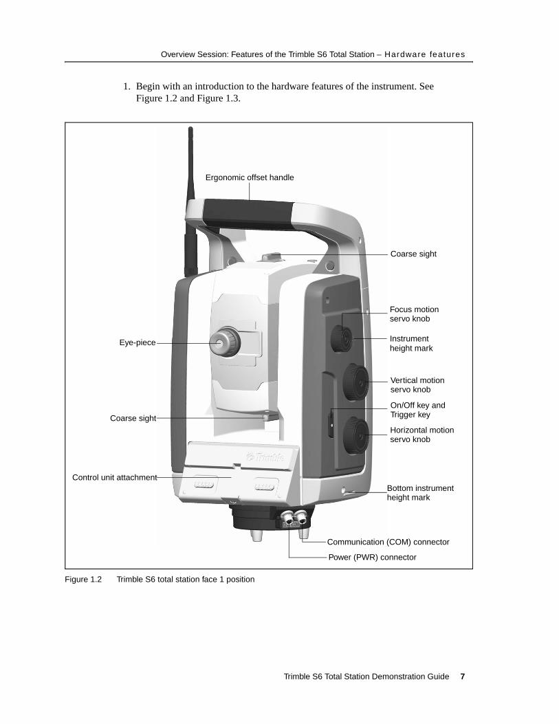
1. Begin with an introduction to the hardware features of the instrument. See Figure 1.2 and Figure 1.3.
Figure 1.2 Trimble S6 total station face 1 position
Ergonomic offset handle
Coarse sight
Focus motion
Instrument
Vertical motion
Horizontal motion
Bottom instrument
On/Off key and
Communication (COM) connector
Power (PWR) connector
Control unit attachment
Coarse sight
Eye-piece
servo knob
servo knob
servo knob
height mark
Trigger key
height mark
Trimble S6 Total Station Demonstration Guide 7
Overview Session: Features of the Trimble S6 Total Station – Hardware features
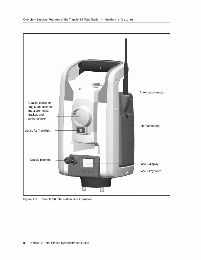
Figure 1.3 Trimble S6 total station face 2 position
Antenna connector
Internal battery
Face 2 display
Face 2 keyboard
Optical plummet
Optics for Tracklight
Coaxial optics forangle and distancemeasurements,tracker, andpointing laser
8 Trimble S6 Total Station Demonstration Guide
Overview Session: Features of the Trimble S6 Total Station – Hardware features
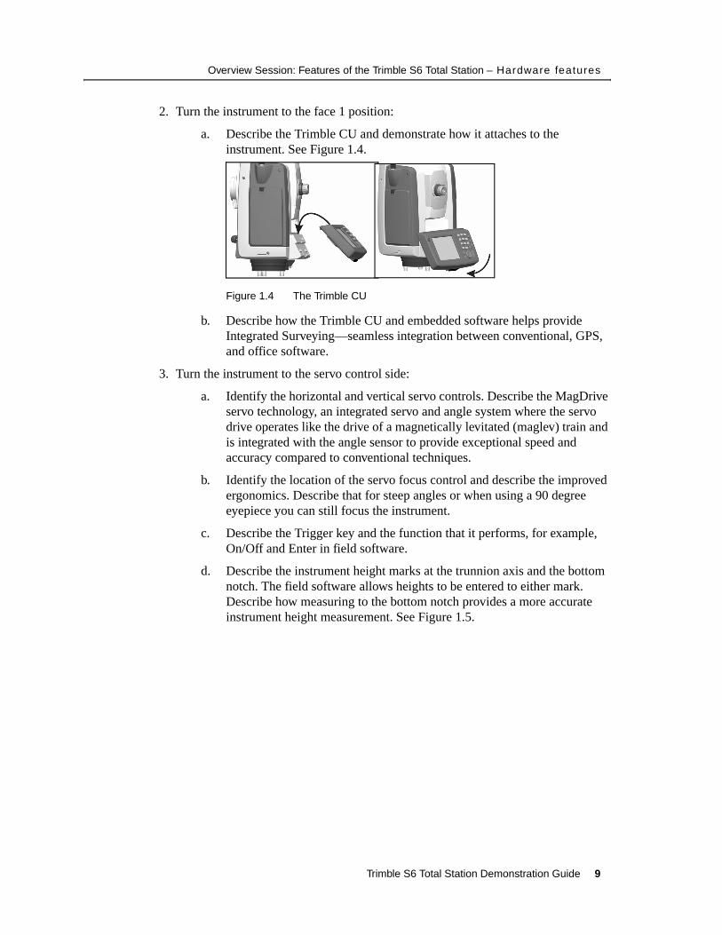
2. Turn the instrument to the face 1 position:
a. Describe the Trimble CU and demonstrate how it attaches to the instrument. See Figure 1.4.
Figure 1.4 The Trimble CU
b. Describe how the Trimble CU and embedded software helps provide Integrated Surveying—seamless integration between conventional, GPS, and office software.
3. Turn the instrument to the servo control side:
a. Identify the horizontal and vertical servo controls. Describe the MagDrive servo technology, an integrated servo and angle system where the servo drive operates like the drive of a magnetically levitated (maglev) train and is integrated with the angle sensor to provide exceptional speed and accuracy compared to conventional techniques.
b. Identify the location of the servo focus control and describe the improved ergonomics. Describe that for steep angles or when using a 90 degree eyepiece you can still focus the instrument.
c. Describe the Trigger key and the function that it performs, for example, On/Off and Enter in field software.
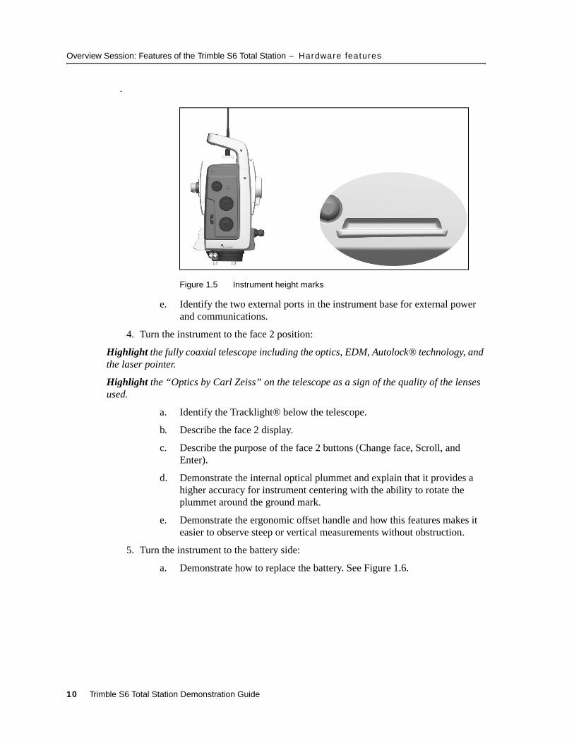
d. Describe the instrument height marks at the trunnion axis and the bottom notch. The field software allows heights to be entered to either mark. Describe how measuring to the bottom notch provides a more accurate instrument height measurement. See Figure 1.5.
Trimble S6 Total Station Demonstration Guide 9
Overview Session: Features of the Trimble S6 Total Station – Hardware features
.
Figure 1.5 Instrument height marks
e. Identify the two external ports in the instrument base for external power and communications.
4. Turn the instrument to the face 2 position:
Highlight the fully coaxial telescope including the optics, EDM, Autolock® technology, and the laser pointer.
Highlight the “Optics by Carl Zeiss” on the telescope as a sign of the quality of the lenses used.
a. Identify the Tracklight® below the telescope.
b. Describe the face 2 display.
c. Describe the purpose of the face 2 buttons (Change face, Scroll, and Enter).
d. Demonstrate the internal optical plummet and explain that it provides a higher accuracy for instrument centering with the ability to rotate the plummet around the ground mark.
e. Demonstrate the ergonomic offset handle and how this features makes it easier to observe steep or vertical measurements without obstruction.
5. Turn the instrument to the battery side:
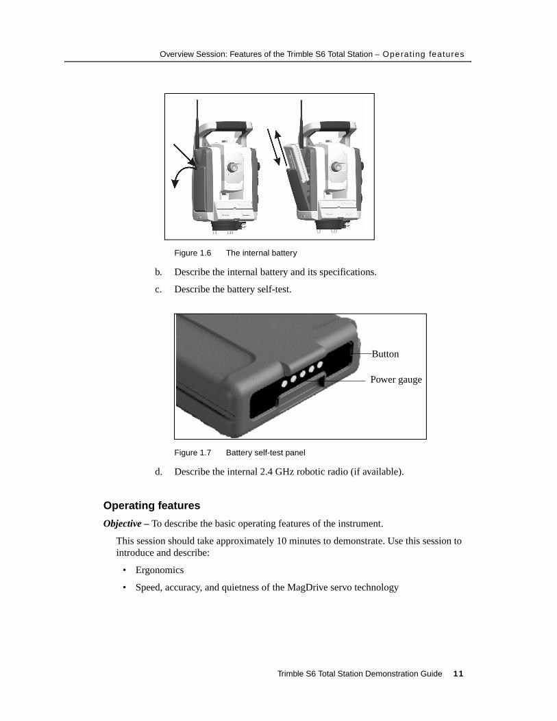
a. Demonstrate how to replace the battery. See Figure 1.6.
10 Trimble S6 Total Station Demonstration Guide
Overview Session: Features of the Trimble S6 Total Station – Operat ing features
Figure 1.6 The internal battery
b. Describe the internal battery and its specifications.
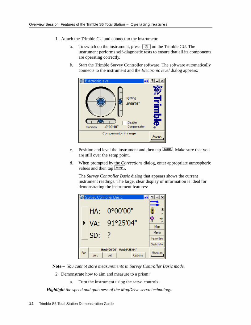
c. Describe the battery self-test.
Figure 1.7 Battery self-test panel
d. Describe the internal 2.4 GHz robotic radio (if available).
10.1 Operating features
Objective – To describe the basic operating features of the instrument.
This session should take approximately 10 minutes to demonstrate. Use this session to introduce and describe:
• Ergonomics
• Speed, accuracy, and quietness of the MagDrive servo technology
Button
Power gauge
Trimble S6 Total Station Demonstration Guide 11
Overview Session: Features of the Trimble S6 Total Station – Operat ing features
1. Attach the Trimble CU and connect to the instrument:
a. To switch on the instrument, press on the Trimble CU. The instrument performs self-diagnostic tests to ensure that all its components are operating correctly.
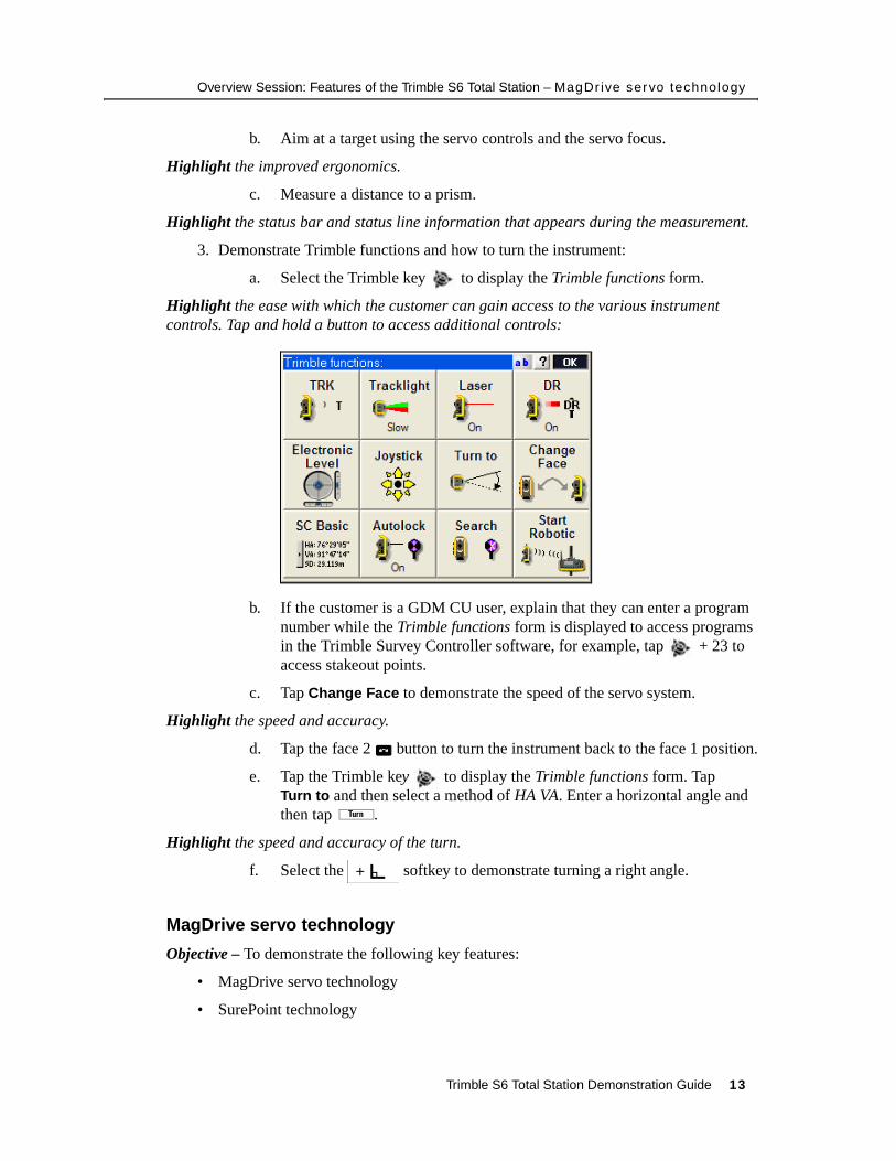
b. Start the Trimble Survey Controller software. The software automatically connects to the instrument and the Electronic level dialog appears:
c. Position and level the instrument and then tap C. Make sure that you are still over the setup point.
d. When prompted by the Corrections dialog, enter appropriate atmospheric values and then tap C.
The Survey Controller Basic dialog that appears shows the current instrument readings. The large, clear display of information is ideal for demonstrating the instrument features:
Note – You cannot store measurements in Survey Controller Basic mode.
2. Demonstrate how to aim and measure to a prism:
a. Turn the instrument using the servo controls.
Highlight the speed and quietness of the MagDrive servo technology.
12 Trimble S6 Total Station Demonstration Guide
Overview Session: Features of the Trimble S6 Total Station – MagDr ive servo technology
b. Aim at a target using the servo controls and the servo focus.
Highlight the improved ergonomics.
c. Measure a distance to a prism.
Highlight the status bar and status line information that appears during the measurement.
3. Demonstrate Trimble functions and how to turn the instrument:
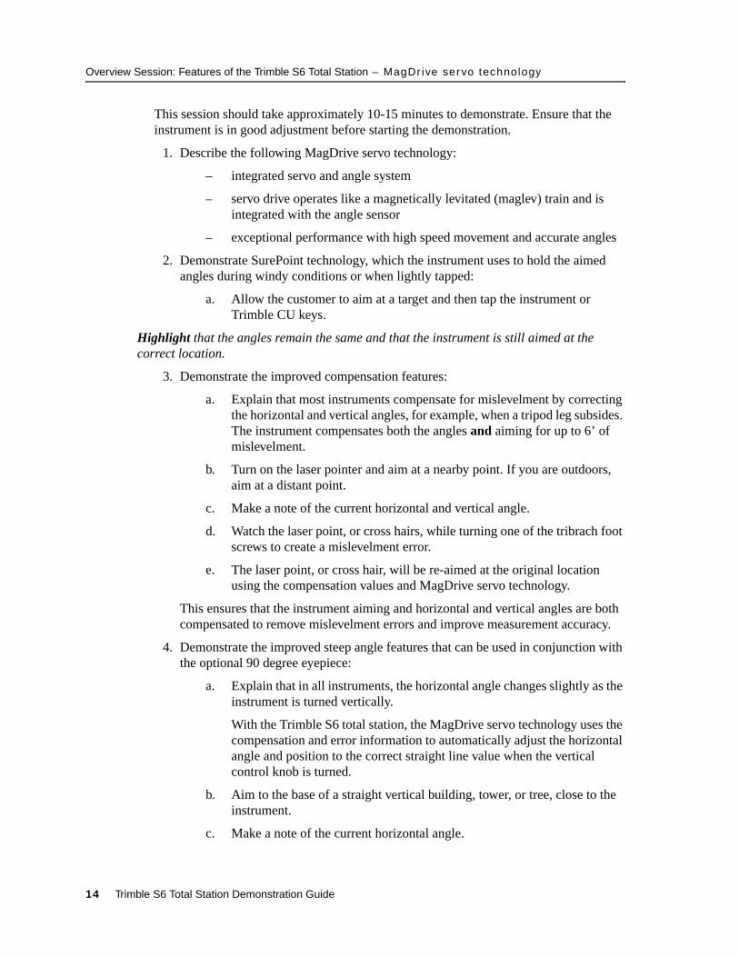
a. Select the Trimble key to display the Trimble functions form.
Highlight the ease with which the customer can gain access to the various instrument controls. Tap and hold a button to access additional controls:
b. If the customer is a GDM CU user, explain that they can enter a program number while the Trimble functions form is displayed to access programs in the Trimble Survey Controller software, for example, tap + 23 to access stakeout points.
c. Tap Change Face to demonstrate the speed of the servo system.
Highlight the speed and accuracy.
d. Tap the face 2 button to turn the instrument back to the face 1 position.
e. Tap the Trimble key to display the Trimble functions form. Tap Turn to and then select a method of HA VA. Enter a horizontal angle and then tap ã.
Highlight the speed and accuracy of the turn.
f. Select the softkey to demonstrate turning a right angle.
10.1 MagDrive servo technology
Objective – To demonstrate the following key features:
• MagDrive servo technology
• SurePoint technology
Trimble S6 Total Station Demonstration Guide 13
Overview Session: Features of the Trimble S6 Total Station – MagDr ive servo technology
This session should take approximately 10-15 minutes to demonstrate. Ensure that the instrument is in good adjustment before starting the demonstration.
1. Describe the following MagDrive servo technology:
– integrated servo and angle system
– servo drive operates like a magnetically levitated (maglev) train and is integrated with the angle sensor
– exceptional performance with high speed movement and accurate angles
2. Demonstrate SurePoint technology, which the instrument uses to hold the aimed angles during windy conditions or when lightly tapped:
a. Allow the customer to aim at a target and then tap the instrument or Trimble CU keys.
Highlight that the angles remain the same and that the instrument is still aimed at the correct location.
3. Demonstrate the improved compensation features:
a. Explain that most instruments compensate for mislevelment by correcting the horizontal and vertical angles, for example, when a tripod leg subsides. The instrument compensates both the angles and aiming for up to 6’ of mislevelment.
b. Turn on the laser pointer and aim at a nearby point. If you are outdoors, aim at a distant point.
c. Make a note of the current horizontal and vertical angle.
d. Watch the laser point, or cross hairs, while turning one of the tribrach foot screws to create a mislevelment error.
e. The laser point, or cross hair, will be re-aimed at the original location using the compensation values and MagDrive servo technology.
This ensures that the instrument aiming and horizontal and vertical angles are both compensated to remove mislevelment errors and improve measurement accuracy.
4. Demonstrate the improved steep angle features that can be used in conjunction with the optional 90 degree eyepiece:
a. Explain that in all instruments, the horizontal angle changes slightly as the instrument is turned vertically.
With the Trimble S6 total station, the MagDrive servo technology uses the compensation and error information to automatically adjust the horizontal angle and position to the correct straight line value when the vertical control knob is turned.
b. Aim to the base of a straight vertical building, tower, or tree, close to the instrument.
c. Make a note of the current horizontal angle.
14 Trimble S6 Total Station Demonstration Guide
Overview Session: Features of the Trimble S6 Total Station – Mul t iTrack technology
d. Turn the vertical control knob to turn the instrument upward.
Note that the horizontal angle remains the same and that a perfect vertical line can be extended by simply turning the vertical control knob.
5. Demonstrate extending a horizontal line:
a. Explain that the traditional way of setting out a horizontal straight line in a direction exactly opposite to a given horizontal direction is to transit the telescope 180° by just turning the vertical control knob. For an accurate result, this technique requires a perfectly adjusted axis without horizontal collimation errors.
The Trimble S6 total station uses the compensator and error information with MagDrive servo technology to remove this limitation.
b. Aim to a point approximately 30 meters from the instrument and then turn the vertical control knob to transit the telescope 180°.
c. Make a note of the current horizontal angle and mark a point approximately 30 meters from the instrument.
d. Check the direction established by turning a horizontal angle between the two points.
The angle should be 180° degrees, which proves that an accurate horizontal straight line direction was established by simply transiting the telescope using the vertical control knob.
10.1 MultiTrack technology
Objective – To demonstrate the following key features:
• Autolock technology
• Target ID
This session should take approximately 10 minutes to demonstrate:
1. Describe that Autolock technology in the Trimble S6 total station can lock and track prism or passive targets:
– The active LED of the Trimble 5600 has been integrated into the instrument, which allows the instrument to track a larger variety of passive targets without the need for a powered rod.
This improvement means that the Autolock performance now matches that of the Trimble 5600 instrument.
Trimble S6 Total Station Demonstration Guide 15
Overview Session: Features of the Trimble S6 Total Station – Mult iTrack technology
2. Demonstrate the performance of automatically locking to a prism:
a. Select Trimble functions and then tap Autolock. By default the instrument snaps onto a target when it is within the field of view. This can be configured in the Autolock settings.
b. Aim at a prism. Once the prism is within the field of view the instrument automatically locks onto the target.
Highlight the status bar and status line information that is displayed to indicate the instrument states.
c. Move the prism around to highlight the tracking capabilities, both in clear visibility and around obstacles.
d. Loose lock and then select search to highlight the speed of regaining lock.
3. Describe that Target ID is available to provide quick and reliable target acquisition:
– Target ID uses an active Target ID unit at the rod to ensure that the correct target is always locked and tracked.
– Target ID allows multiple targets with different IDs to be used on the one site without fear of measuring to the wrong target.
4. Demonstrate the performance of Target ID:
a. Place two prisms on the site. For example one as the backsight and one on the rod with the Target ID.
b. Turn on the Target ID.
c. Set the Target ID to an appropriate value (1-8).
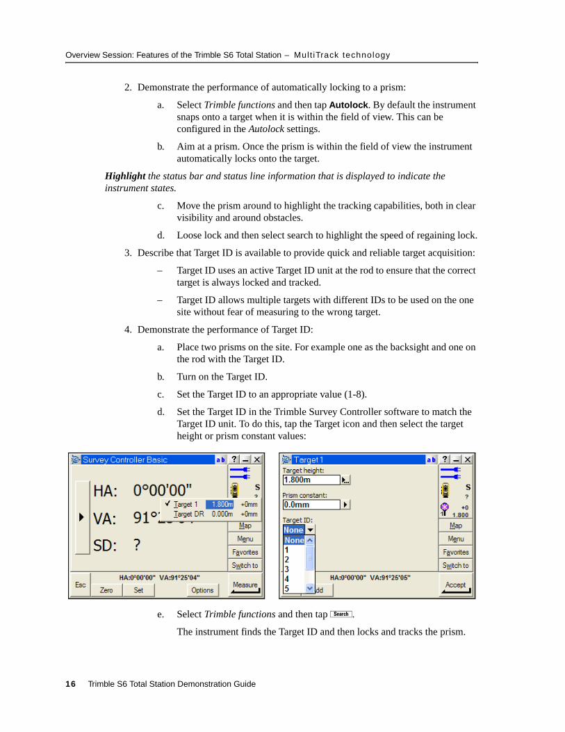
d. Set the Target ID in the Trimble Survey Controller software to match the Target ID unit. To do this, tap the Target icon and then select the target height or prism constant values:
e. Select Trimble functions and then tap æ.
The instrument finds the Target ID and then locks and tracks the prism.
16 Trimble S6 Total Station Demonstration Guide
Overview Session: Features of the Trimble S6 Total Station – Robot ic connect ion
10.1 Robotic connection
If the radio channels are correctly configured, a robotic connection can be established without having to attach the CU to the instrument.
Turn on the instrument using the trigger key and then proceed to Step 2 below. If necessary, use the face 2 display to level the instrument and to configure the radio.
To prepare the instrument for robotics:
1. From the main menu, select Instrument / Radio settings to configure the radio. Tap C to accept the configuration.
2. Select Trimble functions and then tap Start Robotics.
3. Select Autocentered for the Trimble Survey Controller software to perform a search centered around the instrument’s current horizontal and vertical angle.
4. Tap k to suspend the Trimble CU ready for robotic operation.
5. Remove the Trimble CU from the instrument.
To connect to the Trimble S6 total station through robotics:
1. Attach the Trimble CU to the Advanced CU holder.
2. Press on the Trimble CU. The Trimble Survey Controller software automatically powers on the Advanced CU holder radio and connects to the instrument.
To use the map to assist robotic operation once a survey has been started:
1. Select Map to open the map display. Once the station setup is completed, the current orientation of the instrument is shown by a dotted line extending from the instrument to the end of the screen. The target is shown as a cross when a distance is measured.
2. Make sure there is nothing selected on the map. Tap and hold a blank part of the map that corresponds to your approximate location. The tap and hold action displays a menu of options available from the map.
3. Select Turn to from the tap and hold menu. The instrument turns to your approximate location.
Highlight this technique as a very useful method of re-establishing lock during robotics.
Trimble S6 Total Station Demonstration Guide 17
Overview Session: Features of the Trimble S6 Total Station – Summary
10.1 Summary
This section described the following key features and benefits of the Trimble S6 total station.
Feature Benefits
MagDrive servo technology Integrated angle and servo system. The next generation in servo-driven total stations. Extremely fast, accurate, and quiet movement.
SurePoint technology Accurate aiming is retained providing confidence in obtaining accurate measurements.
MultiTrack technology Improved flexibility, range, and accuracy to conventional prisms.
Trimble DR technology Fast, accurate, long range measurements.
Integrated surveying Seamless integration with conventional, GPS, and office software.
Servo focus Improved ergonomics for fast, easy, and convenient focusing.
Target ID Search with Target ID to always locate and track the correct target.
Coaxial optics, EDM, Autolock, Laser Pointer
Fully coaxial instrument provides ideal measurement confidence.
High-capacity internal Battery Li-ion internal “smart” battery provides long operation time with accurate battery discharge information.
Trimble CU—detachable WindowsCE controller
The Trimble CU is a rugged controller that incorporates a sophisticated graphical display and Bluetooth® wireless technology to interface to Trimble sensors.
Tracklight High visibility red/green tracklight for aligning pole person on line.
Face 2 display View measurements and perform survey tasks without having to view only the face 1 display.
Built-in rotating optical plummet
Built in optical plummet provides high accuracy centering tool to ensure accurate results.
Ergonomic offset handle Perform efficient surface scans or vertical measurements without being obstructed by the handle.
18 Trimble S6 Total Station Demonstration Guide
Field Sessions – Session 1: Basic stat ion setup, and topographic measurement
1.1 Field SessionsThe following field sessions describe how to best demonstrate the Trimble S6 total station using the Trimble Survey Controller software for various applications. It is not intended that you complete all field sessions during a demonstration. Use the sessions to tailor a demonstration to suit your customers’ applications and needs.
The sessions can also be performed using a Servo, Autolock, or Robotic instrument. Before you start the field session, connect or configure the instrument using the method that you will demonstrate.
11.1 Session 1: Basic station setup, and topographic measurement
Objective – To describe how to create a job, set up a station, and measure topographic points:
• Applications – Basic control, topographic surveys
• Features – Instrument and software functionality
• Benefits – Ease of use, functionality, productivity
This session should take approximately 20-30 minutes to demonstrate.
Creating a job
Note – When you create a new job, settings from the previous job are used as the defaults.
Create a new job using a coordinate system of scale factor only (1.000000), link the Survey Control.CSV file, select the Road and Boundary.DXF background map, and select the Default Feature and Attribute library:
1. Tap to exit Survey Controller Basic mode. The main Trimble Survey Controller menu appears, and you can begin a survey.
2. Select Files / New job and then enter a job name.
3. Select the button next to Coord. Sys:
a. Select Scale factor only and then tap n.
b. Enter a scale factor as required (1.000000).
c. Tap q to accept and use the scale factor.
4. Select the button next to Units:
a. Demonstrate and verify the various units.
b. Tap a to accept the units.
Trimble S6 Total Station Demonstration Guide 19
Field Sessions – Session 1: Basic stat ion setup, and topographic measurement
5. Select the button next to Linked files:
a. Tap the file Survey Control.CSV so that it is selected (indicated by the check mark ).
b. Tap a to accept the linked file.
6. Select the button next to Background files:
a. Tap the file Road and Boundary.dxf so that the file is selected (indicated by the check mark ).
b. Tap a to accept the background file.
7. Select the button next to Feature library:
– Tap Default to select the default feature code library.
8. Tap a to create the job.
Note – To modify the properties of this new job at any stage, select Files / Properties of current job. Each button displays the current settings. Tap a button to change the settings.
Setting up a station
Perform a station setup on point 1, with point 2 as the backsight:
1. Place two markers in the ground to use as point 1 and point 2 from the training data. Place point 2 approximately 40 meters from point 1.
2. Set up the instrument on point 1 and then place the prism or target on point 2.
3. From the Trimble Survey Controller main menu, select Survey / Station setup.
4. Set appropriate Corrections values and then tap a.
5. Enter the station setup details:
a. Enter the instrument point name (1), or tap the field pop-up arrow, then tap List and select Point 1.
b. Enter the instrument height.
Note – The instrument height can be defined as measured to the True Height or to the Bottom Notch. Use True Height when measuring to the cross that corresponds to the centre of the trunnion axis. Use Bottom Notch when measuring to the bottom notch of the instrument. Use the advanced pop-up menu to select the measurement method (True Height is used by default).
c. Enter the backsight point name (2) and the backsight height.
d. Enter the Azimuth to the backsight point (2) as 0.
e. Select a measurement method of Angles and Distance.
20 Trimble S6 Total Station Demonstration Guide
Field Sessions – Session 1: Basic stat ion setup, and topographic measurement
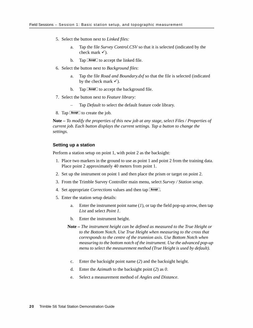
6. Aim to the backsight point and then tap m. The measurement result appears:
7. Tap q to accept and complete the station setup.
Measuring topographic points
Set up three prisms or targets within the survey area to use for this and later tasks. These points will be measured and can be used later as control for a resection. To do this:
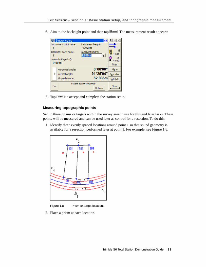
1. Identify three evenly spaced locations around point 1 so that sound geometry is available for a resection performed later at point 1. For example, see Figure 1.8.
Figure 1.8 Prism or target locations
2. Place a prism at each location.
Trimble S6 Total Station Demonstration Guide 21
Field Sessions – Session 1: Basic stat ion setup, and topographic measurement
3. From the main menu, select Survey / Measure topo and then enter the details for the point to measure:
a. Enter the point name (for example, 1001) and then select a feature code from the default library (for example, SS for Survey Station).
b. Select a measurement method of Angles and distance.
c. Enter the target height. Make a note of the point name and target height if you intend to use this for resection later.
B Tip – To alternate between targets or to edit the target height and the prism constant:1. Tap the target icon on the status bar . 2. Select the target name to change to that target. 3. To open the Target Details form for editing, select the target height or prism constant. You can create up to five non-DR targets.
4. Aim to the first point and then tap m.
While the instrument is measuring, the instrument icon becomes animated and Measuring appears on the status line during a measurement. Once the measurement is completed, the angles and distance appear.
5. Tap s to store the point.
6. Measure the second point:
a. Modify the target height as necessary for the second point (1002). Make a note of the point name and target height if you intend to use this for resection later.
b. Aim to the point 1002 and then tap m.
c. Tap s to store the point.
7. Measure the third point:
a. Modify the target height as necessary for the third point (1003). Make a note of the point name and target height if you intend to use this for resection later.
b. Aim to point 1003 and then tap m.
c. Tap s to store the point.
Measuring topographic points: fast method
To measure topographic points quickly, use the TRK EDM mode:
1. Tap the Trimble key to display the Trimble functions form and then tap TRK. Distances are now continuously measured and displayed on the status line.
2. Change the measurement method to Angles and Distance. The current measurement is displayed and continuously updated.
3. Tap s to store points as required. The fast update rate and continuous display of the measurement allows points to be stored almost instantaneously.
22 Trimble S6 Total Station Demonstration Guide
Field Sessions – Session 1: Basic stat ion setup, and topographic measurement
4. Tap the Trimble key to display the Trimble functions form and then tap STD to change the EDM mode back to a standard measurement.
Measuring offset points
Objects such as trees, posts, or power poles cannot be directly measured because you cannot place a prism at the centre of the object. This section describes some of the offset measurement options and instrument modes that you can use for inaccessible objects.
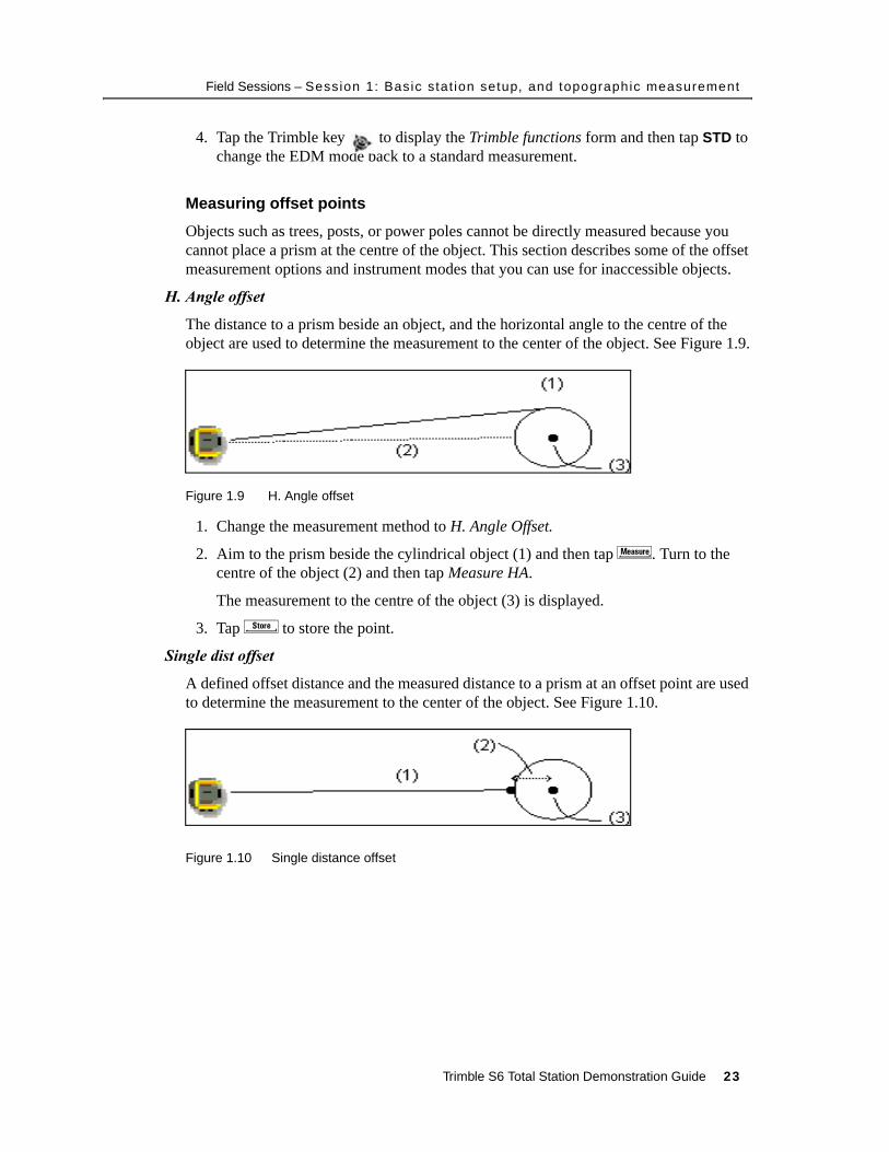
H. Angle offset
The distance to a prism beside an object, and the horizontal angle to the centre of the object are used to determine the measurement to the center of the object. See Figure 1.9.
Figure 1.9 H. Angle offset
1. Change the measurement method to H. Angle Offset.
2. Aim to the prism beside the cylindrical object (1) and then tap m. Turn to the centre of the object (2) and then tap Measure HA.
The measurement to the centre of the object (3) is displayed.
3. Tap s to store the point.
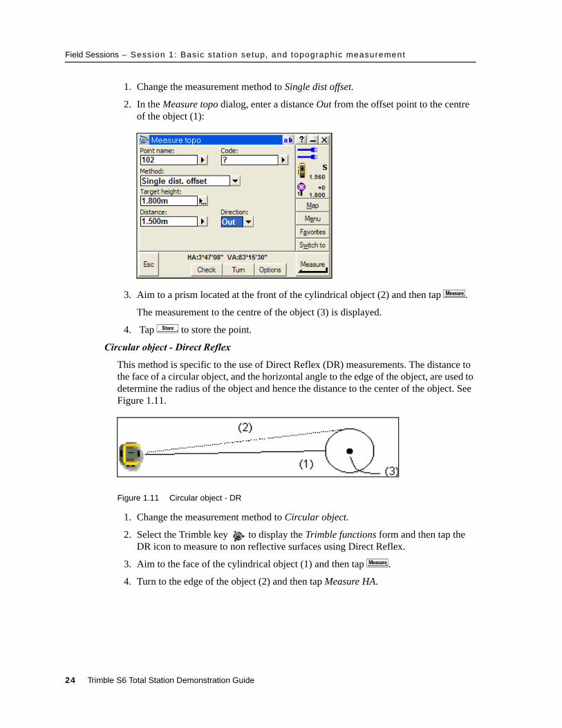
Single dist offset
A defined offset distance and the measured distance to a prism at an offset point are used to determine the measurement to the center of the object. See Figure 1.10.
Figure 1.10 Single distance offset
Trimble S6 Total Station Demonstration Guide 23
Field Sessions – Session 1: Basic stat ion setup, and topographic measurement
1. Change the measurement method to Single dist offset.
2. In the Measure topo dialog, enter a distance Out from the offset point to the centre of the object (1):
3. Aim to a prism located at the front of the cylindrical object (2) and then tap m.
The measurement to the centre of the object (3) is displayed.
4. Tap s to store the point.
Circular object - Direct Reflex
This method is specific to the use of Direct Reflex (DR) measurements. The distance to the face of a circular object, and the horizontal angle to the edge of the object, are used to determine the radius of the object and hence the distance to the center of the object. See Figure 1.11.
Figure 1.11 Circular object - DR
1. Change the measurement method to Circular object.
2. Select the Trimble key to display the Trimble functions form and then tap the DR icon to measure to non reflective surfaces using Direct Reflex.
3. Aim to the face of the cylindrical object (1) and then tap m.
4. Turn to the edge of the object (2) and then tap Measure HA.
24 Trimble S6 Total Station Demonstration Guide
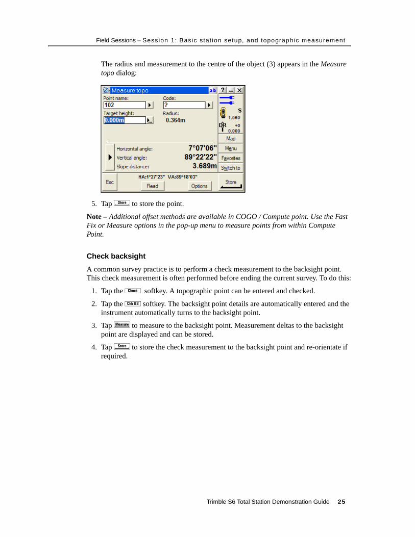
Field Sessions – Session 1: Basic stat ion setup, and topographic measurement
The radius and measurement to the centre of the object (3) appears in the Measure topo dialog:
5. Tap s to store the point.
Note – Additional offset methods are available in COGO / Compute point. Use the Fast Fix or Measure options in the pop-up menu to measure points from within Compute Point.
Check backsight
A common survey practice is to perform a check measurement to the backsight point. This check measurement is often performed before ending the current survey. To do this:
1. Tap the Ï softkey. A topographic point can be entered and checked.
2. Tap the Ð softkey. The backsight point details are automatically entered and the instrument automatically turns to the backsight point.
3. Tap m to measure to the backsight point. Measurement deltas to the backsight point are displayed and can be stored.
4. Tap s to store the check measurement to the backsight point and re-orientate if required.
Trimble S6 Total Station Demonstration Guide 25
Field Sessions – Session 2: Advanced stat ion setup, and automated rounds
10.1 Session 2: Advanced station setup, and automated rounds
Objective – To describe advanced station setup (resection) and how to control measurements:
• Applications – Traversing, control surveys
• Features – Autolock technology, automated rounds, instrument speed
• Benefits – Accuracy, speed, productivity
This session should take approximately 30 minutes to demonstrate.
Resection
A resection uses measurements to known points to determine the coordinates of the instrument point and the horizontal orientation. Perform a resection using three previously measured points.
1. Although not essential for the resection, set up the instrument on point 1. You can then use the resection result to compare to the original coordinates of point 1.
2. Set up prisms or targets on three known or previously measured points. These points will be used as the backsight points during the resection.
3. To start the resection:
a. From the main menu, select Survey / Resection.
b. Set appropriate Corrections values and then tap a.
c. Enter the instrument details including the Point name (for example, 10) and the Instrument height.
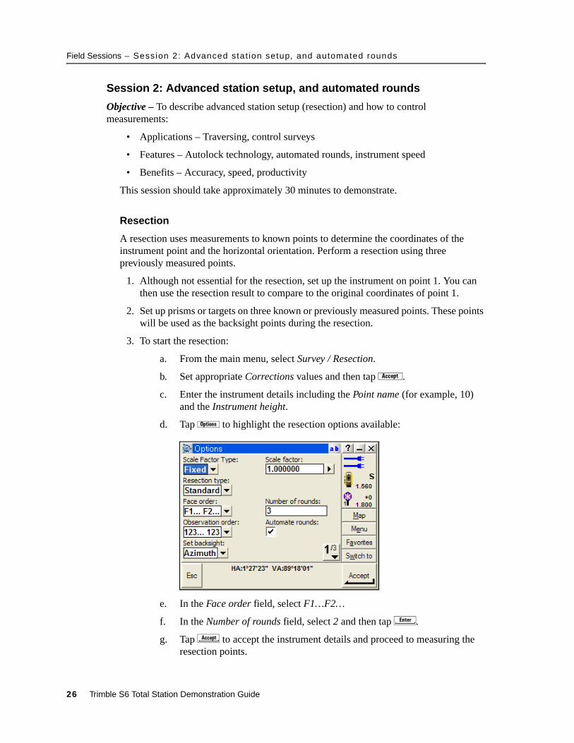
d. Tap o to highlight the resection options available:
e. In the Face order field, select F1…F2…
f. In the Number of rounds field, select 2 and then tap E.
g. Tap C to accept the instrument details and proceed to measuring the resection points.
26 Trimble S6 Total Station Demonstration Guide

Field Sessions – Session 2: Advanced stat ion setup, and automated rounds
4. Measure the first resection point:
a. Enter the details of the first backsight point including the Point name and the correct Target height.
B Tip – To easily select the Point name, tap the pop-up arrow and then select List from the menu that appears. Tap the point and then select Accept to add the point to the Point name field.
b. Use the coarse sight to aim the instrument to the target at the first backsight point.
c. Select the Trimble key to display the Trimble functions form. Tap Autolock. The instrument automatically locks onto the target.
d. Tap m to measure to the first backsight point.
5. Measure the second resection point:
a. Enter the details of the second backsight point, including the Point name and the correct Target height.
b. Aim the instrument to the target at the second backsight point. The instrument automatically locks onto the target.
c. Tap m to measure to the second backsight point.
Note – The resection calculation requires a minimum of two points to determine a solution. Once two points have been measured, the Resection – Residuals are displayed. Additional points can be added, measurements and residuals reviewed, or the current solution accepted.
6. Add the third point to the resection:
a. Tap the [+Point] softkey.
b. Enter the details of the third backsight point, including the Point name and the correct Target height.
B Tip – Once a resection solution appears, the field software uses the current result to turn the instrument to the next point. Enter the point name and the correct target height to allow the instrument to turn to the correct location.
c. Tap m to measure to the third backsight point.
Trimble S6 Total Station Demonstration Guide 27
Field Sessions – Session 2: Advanced stat ion setup, and automated rounds
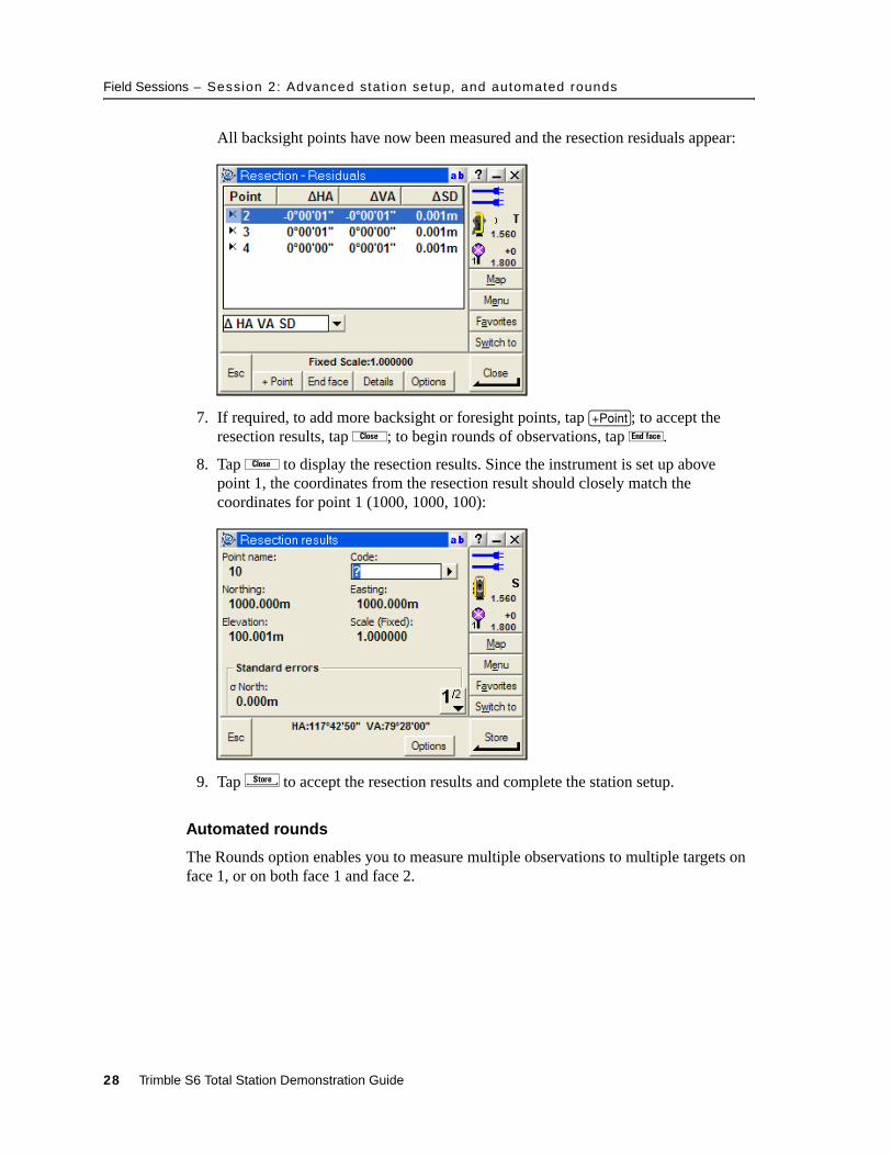
All backsight points have now been measured and the resection residuals appear:
7. If required, to add more backsight or foresight points, tap [+Point]; to accept the resection results, tap `; to begin rounds of observations, tap é.
8. Tap ` to display the resection results. Since the instrument is set up above point 1, the coordinates from the resection result should closely match the coordinates for point 1 (1000, 1000, 100):
9. Tap s to accept the resection results and complete the station setup.
Automated rounds
The Rounds option enables you to measure multiple observations to multiple targets on face 1, or on both face 1 and face 2.
28 Trimble S6 Total Station Demonstration Guide
Field Sessions – Session 2: Advanced stat ion setup, and automated rounds
Highlight the speed and accuracy of the MagDrive servo technology.
In measuring rounds, you must first make one measurement to each of the points to be measured. Then the instrument takes over, completing the measurement sets automatically:
1. Set up the instrument on point 1 and then perform a station setup to point 2 (or use the station setup defined by the resection on page 26).
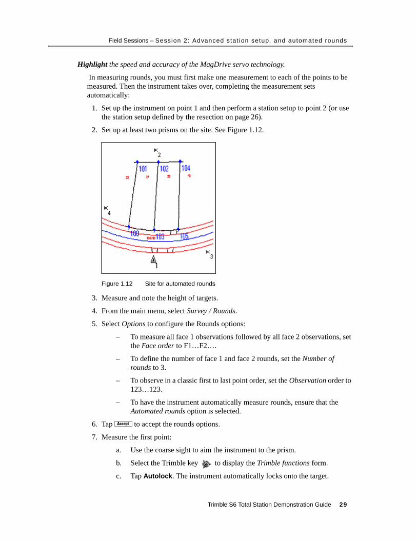
2. Set up at least two prisms on the site. See Figure 1.12.
Figure 1.12 Site for automated rounds
3. Measure and note the height of targets.
4. From the main menu, select Survey / Rounds.
5. Select Options to configure the Rounds options:
– To measure all face 1 observations followed by all face 2 observations, set the Face order to F1…F2….
– To define the number of face 1 and face 2 rounds, set the Number of rounds to 3.
– To observe in a classic first to last point order, set the Observation order to 123…123.
– To have the instrument automatically measure rounds, ensure that the Automated rounds option is selected.
6. Tap a to accept the rounds options.
7. Measure the first point:
a. Use the coarse sight to aim the instrument to the prism.
b. Select the Trimble key to display the Trimble functions form.
c. Tap Autolock. The instrument automatically locks onto the target.
Trimble S6 Total Station Demonstration Guide 29
Field Sessions – Session 2: Advanced stat ion setup, and automated rounds
d. Enter the details of the point, including the Point name and the correct Target height.
e. Tap m to measure to the point.
8. To measure the second point, repeat Step a through Step e above.
9. Measure additional points as required.
10.Tap é to complete the current face and begin measuring automated rounds.
The instrument turns and measures all points automatically until the required number of rounds is completed.
Highlight Use this time to highlight survey applications (control and traversing) that are of most benefit to this type of measurement. Also highlight the speed and accuracy of the MagDrive servo technology and the productivity gains that can be achieved with the Trimble S6 total station.
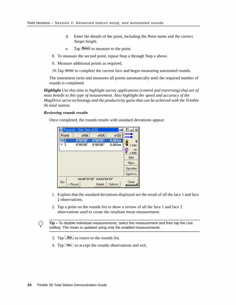
Reviewing rounds results
Once completed, the rounds results with standard deviations appear:
1. Explain that the standard deviations displayed are the result of all the face 1 and face 2 observations.
2. Tap a point on the rounds list to show a review of all the face 1 and face 2 observations used to create the resultant mean measurement.
B Tip – To disable individual measurements, select the measurement and then tap the Use softkey. The mean is updated using only the enabled measurements.
3. Tap to return to the rounds list.
4. Tap ` to accept the rounds observations and exit.
30 Trimble S6 Total Station Demonstration Guide

Field Sessions – Session 2: Advanced stat ion setup, and automated rounds
Review stored results
To review and edit survey data after it is stored:
• Select Files / Review current job to review how the data is stored and how it can be edited. Discuss how the job is like a field book. Changes can be made and coordinates are recomputed, but the original values are always retained for quality assurance, for example, a target height change.
• Select Files / Point manager to review and edit data in a tabular view. Tap the column header to sort the data. Tap + to expand the details for a point. Tap the Ö softkey to select a different view of the data.
• Select Files / QC Graph to review and edit data graphically. For example, to review target heights. Tap a bar on the graph to display the details of the data. Tap V to display and edit the full details. Tap the Ö softkey to select a different view of the data.
Trimble S6 Total Station Demonstration Guide 31
Field Sessions – Session 3: Staking out points and l ines
10.1 Session 3: Staking out points and lines
Objective – To describe common stakeout tasks involving stakeout points and lines:
• Applications – Basic stakeout and construction stakeout applications
• Features – MagDrive servo technology, Target ID, upgradeability
• Benefits – Functionality, productivity
This session should take approximately 20-30 minutes to demonstrate. Use Servo, Autolock, or Robotics depending on the needs of the users.
Staking out points
Various options can be configured when staking out points. This section describes some of the common workflows.
Stake out points
Points are commonly staked out to define locations of interest either for construction, earthwork, or cadastral type applications. In the stakeout workflow, you select a point, navigate to the point, and then accept the measurement. To do this:
1. Set up the instrument on point 1 and then perform a station setup to point 2.
2. From the main menu select Survey / Stakeout / Points. If enabled, turn off Autolock technology through Trimble functions.
3. Select the points to add to the stakeout list:
a. Select A to add points to the stakeout list. Various methods to select points and add them to the stakeout list are available.
b. Select the Enter single point name method.
c. Enter the name of one of the resection points (or a previously measured point) and then tap A to add the point to the stakeout list.
d. Tap to exit Enter single point name and display the stakeout list.
32 Trimble S6 Total Station Demonstration Guide
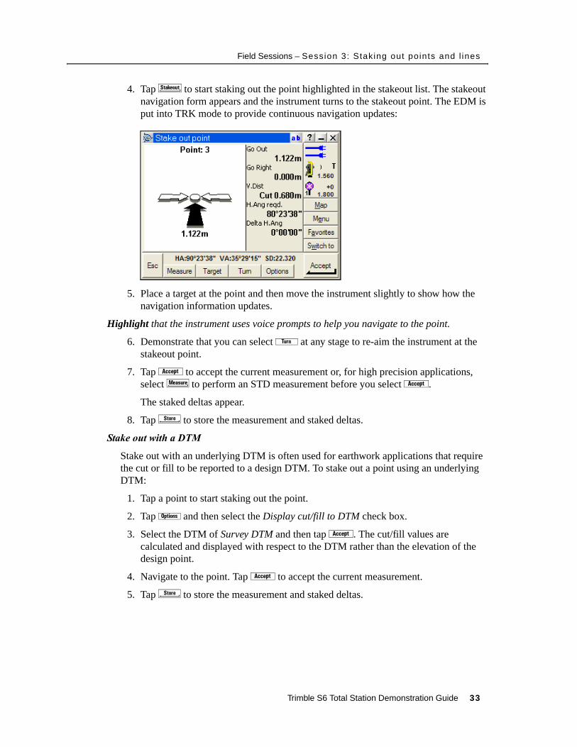
Field Sessions – Session 3: Staking out points and l ines
4. Tap S to start staking out the point highlighted in the stakeout list. The stakeout navigation form appears and the instrument turns to the stakeout point. The EDM is put into TRK mode to provide continuous navigation updates:
5. Place a target at the point and then move the instrument slightly to show how the navigation information updates.
Highlight that the instrument uses voice prompts to help you navigate to the point.
6. Demonstrate that you can select ã at any stage to re-aim the instrument at the stakeout point.
7. Tap a to accept the current measurement or, for high precision applications, select m to perform an STD measurement before you select a.
The staked deltas appear.
8. Tap s to store the measurement and staked deltas.
Stake out with a DTM
Stake out with an underlying DTM is often used for earthwork applications that require the cut or fill to be reported to a design DTM. To stake out a point using an underlying DTM:
1. Tap a point to start staking out the point.
2. Tap o and then select the Display cut/fill to DTM check box.
3. Select the DTM of Survey DTM and then tap a. The cut/fill values are calculated and displayed with respect to the DTM rather than the elevation of the design point.
4. Navigate to the point. Tap a to accept the current measurement.
5. Tap s to store the measurement and staked deltas.
Trimble S6 Total Station Demonstration Guide 33
Field Sessions – Session 3: Staking out points and l ines
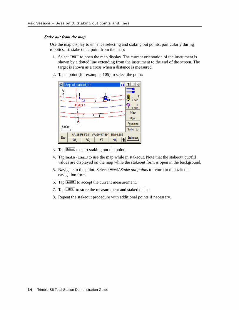
Stake out from the map
Use the map display to enhance selecting and staking out points, particularly during robotics. To stake out a point from the map:
1. Select L to open the map display. The current orientation of the instrument is shown by a dotted line extending from the instrument to the end of the screen. The target is shown as a cross when a distance is measured.
2. Tap a point (for example, 105) to select the point:
3. Tap S to start staking out the point.
4. Tap Q / L to use the map while in stakeout. Note that the stakeout cut/fill values are displayed on the map while the stakeout form is open in the background.
5. Navigate to the point. Select Q / Stake out points to return to the stakeout navigation form.
6. Tap a to accept the current measurement.
7. Tap s to store the measurement and staked deltas.
8. Repeat the stakeout procedure with additional points if necessary.
34 Trimble S6 Total Station Demonstration Guide
Field Sessions – Session 3: Staking out points and l ines
Stake out lines
Lines are often used as a reference guide, particularly in construction applications. To define a position relative to a line or to stake out a line:
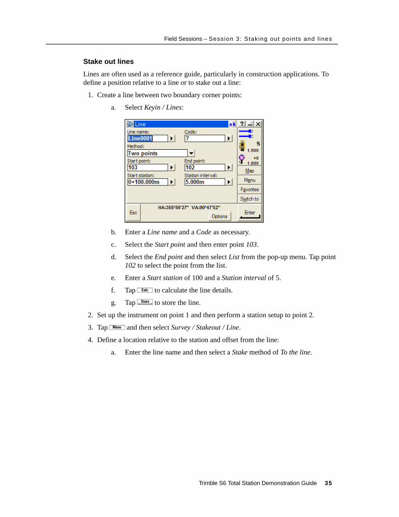
1. Create a line between two boundary corner points:
a. Select Keyin / Lines:
b. Enter a Line name and a Code as necessary.
c. Select the Start point and then enter point 103.
d. Select the End point and then select List from the pop-up menu. Tap point 102 to select the point from the list.
e. Enter a Start station of 100 and a Station interval of 5.
f. Tap Z to calculate the line details.
g. Tap s to store the line.
2. Set up the instrument on point 1 and then perform a station setup to point 2.
3. Tap K and then select Survey / Stakeout / Line.
4. Define a location relative to the station and offset from the line:
a. Enter the line name and then select a Stake method of To the line.
Trimble S6 Total Station Demonstration Guide 35
Field Sessions – Session 3: Staking out points and l ines
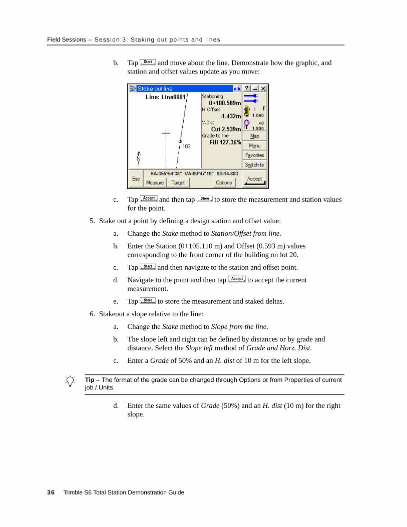
b. Tap x and move about the line. Demonstrate how the graphic, and station and offset values update as you move:
c. Tap C and then tap s to store the measurement and station values for the point.
5. Stake out a point by defining a design station and offset value:
a. Change the Stake method to Station/Offset from line.
b. Enter the Station (0+105.110 m) and Offset (0.593 m) values corresponding to the front corner of the building on lot 20.
c. Tap x and then navigate to the station and offset point.
d. Navigate to the point and then tap C to accept the current measurement.
e. Tap s to store the measurement and staked deltas.
6. Stakeout a slope relative to the line:
a. Change the Stake method to Slope from the line.
b. The slope left and right can be defined by distances or by grade and distance. Select the Slope left method of Grade and Horz. Dist.
c. Enter a Grade of 50% and an H. dist of 10 m for the left slope.
B Tip – The format of the grade can be changed through Options or from Properties of current job / Units.
d. Enter the same values of Grade (50%) and an H. dist (10 m) for the right slope.
36 Trimble S6 Total Station Demonstration Guide
Field Sessions – Session 3: Staking out points and l ines
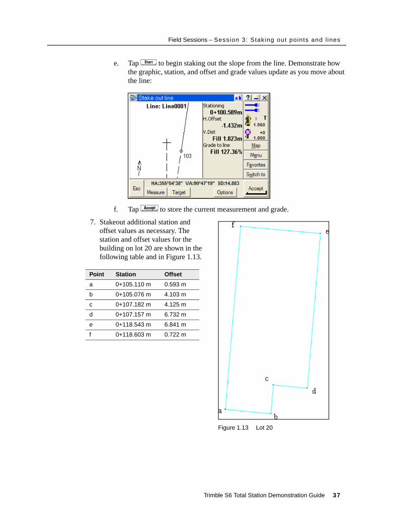
e. Tap x to begin staking out the slope from the line. Demonstrate how the graphic, station, and offset and grade values update as you move about the line:
f. Tap C to store the current measurement and grade.
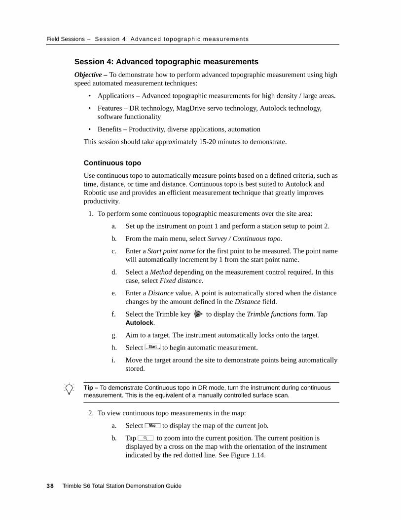
7. Stakeout additional station and offset values as necessary. The station and offset values for the building on lot 20 are shown in the following table and in Figure 1.13.
Figure 1.13 Lot 20
Point Station Offset
a 0+105.110 m 0.593 m
b 0+105.076 m 4.103 m
c 0+107.182 m 4.125 m
d 0+107.157 m 6.732 m
e 0+118.543 m 6.841 m
f 0+118.603 m 0.722 m
Trimble S6 Total Station Demonstration Guide 37
Field Sessions – Session 4: Advanced topographic measurements
10.1 Session 4: Advanced topographic measurements
Objective – To demonstrate how to perform advanced topographic measurement using high speed automated measurement techniques:
• Applications – Advanced topographic measurements for high density / large areas.
• Features – DR technology, MagDrive servo technology, Autolock technology, software functionality
• Benefits – Productivity, diverse applications, automation
This session should take approximately 15-20 minutes to demonstrate.
Continuous topo
Use continuous topo to automatically measure points based on a defined criteria, such as time, distance, or time and distance. Continuous topo is best suited to Autolock and Robotic use and provides an efficient measurement technique that greatly improves productivity.
1. To perform some continuous topographic measurements over the site area:
a. Set up the instrument on point 1 and perform a station setup to point 2.
b. From the main menu, select Survey / Continuous topo.
c. Enter a Start point name for the first point to be measured. The point name will automatically increment by 1 from the start point name.
d. Select a Method depending on the measurement control required. In this case, select Fixed distance.
e. Enter a Distance value. A point is automatically stored when the distance changes by the amount defined in the Distance field.
f. Select the Trimble key to display the Trimble functions form. Tap Autolock.
g. Aim to a target. The instrument automatically locks onto the target.
h. Select x to begin automatic measurement.
i. Move the target around the site to demonstrate points being automatically stored.
B Tip – To demonstrate Continuous topo in DR mode, turn the instrument during continuous measurement. This is the equivalent of a manually controlled surface scan.
2. To view continuous topo measurements in the map:
a. Select L to display the map of the current job.
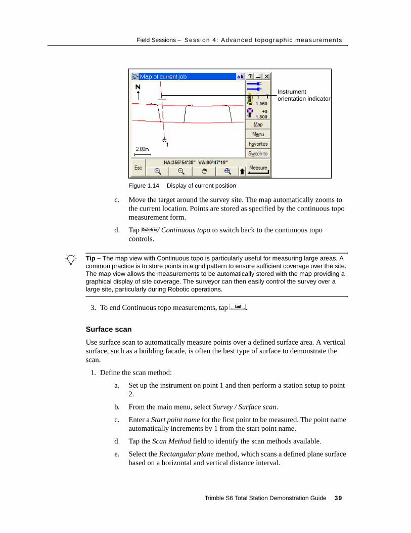
b. Tap N to zoom into the current position. The current position is displayed by a cross on the map with the orientation of the instrument indicated by the red dotted line. See Figure 1.14.
38 Trimble S6 Total Station Demonstration Guide
Field Sessions – Session 4: Advanced topographic measurements
Figure 1.14 Display of current position
c. Move the target around the survey site. The map automatically zooms to the current location. Points are stored as specified by the continuous topo measurement form.
d. Tap Q/ Continuous topo to switch back to the continuous topo controls.
B Tip – The map view with Continuous topo is particularly useful for measuring large areas. A common practice is to store points in a grid pattern to ensure sufficient coverage over the site. The map view allows the measurements to be automatically stored with the map providing a graphical display of site coverage. The surveyor can then easily control the survey over a large site, particularly during Robotic operations.
3. To end Continuous topo measurements, tap e.
Surface scan
Use surface scan to automatically measure points over a defined surface area. A vertical surface, such as a building facade, is often the best type of surface to demonstrate the scan.
1. Define the scan method:
a. Set up the instrument on point 1 and then perform a station setup to point 2.
b. From the main menu, select Survey / Surface scan.
c. Enter a Start point name for the first point to be measured. The point name automatically increments by 1 from the start point name.
d. Tap the Scan Method field to identify the scan methods available.
e. Select the Rectangular plane method, which scans a defined plane surface based on a horizontal and vertical distance interval.
Instrumentorientation indicator
Trimble S6 Total Station Demonstration Guide 39
Field Sessions – Session 4: Advanced topographic measurements
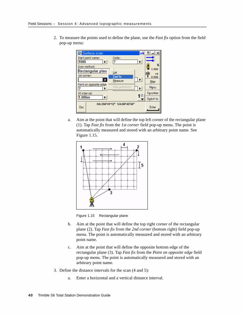
2. To measure the points used to define the plane, use the Fast fix option from the field pop-up menu:
a. Aim at the point that will define the top left corner of the rectangular plane (1). Tap Fast fix from the 1st corner field pop-up menu. The point is automatically measured and stored with an arbitrary point name. See Figure 1.15.
Figure 1.15 Rectangular plane
b. Aim at the point that will define the top right corner of the rectangular plane (2). Tap Fast fix from the 2nd corner (bottom right) field pop-up menu. The point is automatically measured and stored with an arbitrary point name.
c. Aim at the point that will define the opposite bottom edge of the rectangular plane (3). Tap Fast fix from the Point on opposite edge field pop-up menu. The point is automatically measured and stored with an arbitrary point name.
3. Define the distance intervals for the scan (4 and 5):
a. Enter a horizontal and a vertical distance interval.
40 Trimble S6 Total Station Demonstration Guide
Field Sessions – Session 4: Advanced topographic measurements
b. The total number of points that will be measured, and the estimated time for the scan appear.
4. Tap x to commence the scan.
Highlight the speed of the surface scan and the various applications that scanning can be used for.
B Tip – Turn on TRK mode through Trimble functions to provide continuous distance measurements that increases the speed of the surface scan.
Information such as the number of points scanned, points skipped, and time to go, appear during and at the completion of the scan.
5. Tap Pause at any stage to temporarily pause the scan.
6. Tap ` at the completion of the scan to exit.
Trimble S6 Total Station Demonstration Guide 41
Field Sessions – Session 5: Stakeout roads
10.1 Session 5: Stakeout roads
Objective – To demonstrate staking out roads:
• Applications – Road stakeout
• Features – Instrument speed, accuracy, functionality
• Benefits – Functionality, graphics, productivity
This session should take approximately 15-20 minutes to demonstrate.
Staking out a Trimble road
Trimble roads can be created in Trimble Office Software products or manually entered from the Trimble Survey Controller software.
To stake out a Trimble road:
1. Set up the instrument on point 1 and then perform a station setup to point 2.
2. Copy the road definition from the Demo Road.job into the current job.
3. From the main menu, select Survey / Stakeout / Road.
4. Stake out a centerline point on the road:
a. Tap the pop-up arrow for the Road name field and then tap Trimble roads. A check mark appears next to the selected road type.
b. Select List from the pop-up menu for the Road name field and then select the road to stake.
c. Select a Stake method of Station and offset.
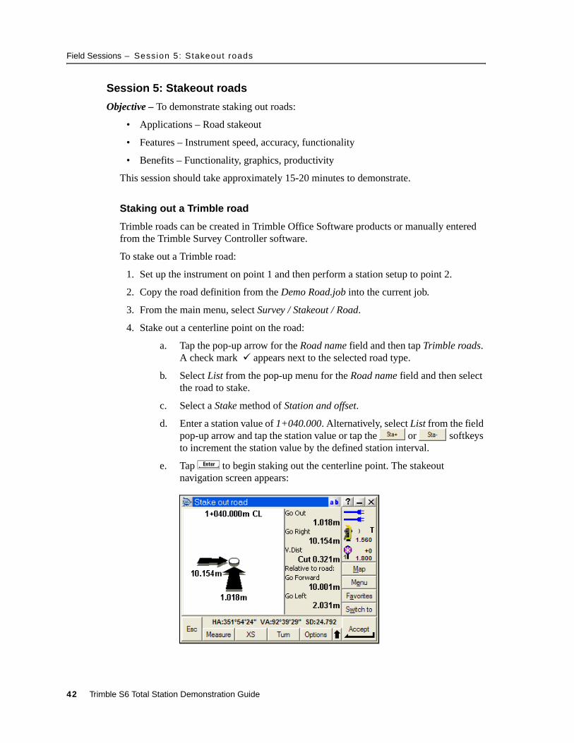
d. Enter a station value of 1+040.000. Alternatively, select List from the field pop-up arrow and tap the station value or tap the or softkeys to increment the station value by the defined station interval.
e. Tap E to begin staking out the centerline point. The stakeout navigation screen appears:
42 Trimble S6 Total Station Demonstration Guide
Field Sessions – Session 5: Stakeout roads
Highlight the use of the graphical display and the instrument voice prompts to help you to navigate to the point.
f. To accept the current measurement, tap a; to remeasure the point, tap m.
g. Tap s to store the measurement and staked deltas.
5. Stake out a template offset point on the road:
a. Enter a station value of 1+040.000.
b. Select List from the Offset field pop-up menu and then tap the 3.000m Offset (right) value.
c. Tap E to begin staking out the template point.
d. To accept the current measurement, tap a; to remeasure the point, tap m.
e. Tap s to store the measurement and staked deltas.
6. Stake out a road catch point. The road catch point is where the side slope of the template intersects with the ground.
a. Enter a station value of 1+040.000.
b. Select List from the Offset field pop-up menu and then tap the right (Side Slope).
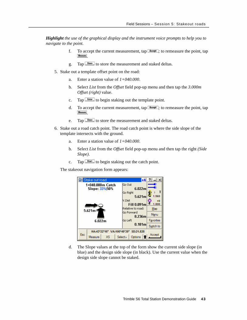
c. Tap x to begin staking out the catch point.
The stakeout navigation form appears:
d. The Slope values at the top of the form show the current side slope (in blue) and the design side slope (in black). Use the current value when the design side slope cannot be staked.
Trimble S6 Total Station Demonstration Guide 43
Field Sessions – Session 5: Stakeout roads
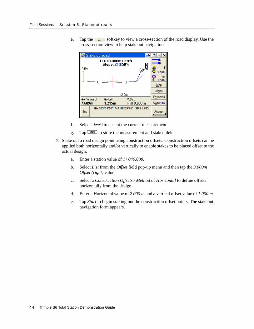
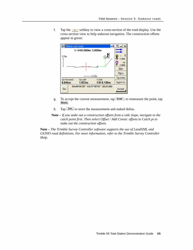
e. Tap the softkey to view a cross-section of the road display. Use the cross-section view to help stakeout navigation:
f. Select a to accept the current measurement.
g. Tap s to store the measurement and staked deltas.
7. Stake out a road design point using construction offsets. Construction offsets can be applied both horizontally and/or vertically to enable stakes to be placed offset to the actual design.
a. Enter a station value of 1+040.000.
b. Select List from the Offset field pop-up menu and then tap the 3.000m Offset (right) value.
c. Select a Construction Offsets / Method of Horizontal to define offsets horizontally from the design.
d. Enter a Horizontal value of 2.000 m and a vertical offset value of 1.000 m.
e. Tap Start to begin staking out the construction offset points. The stakeout navigation form appears.
44 Trimble S6 Total Station Demonstration Guide
Field Sessions – Session 5: Stakeout roads
f. Tap the softkey to view a cross-section of the road display. Use the cross-section view to help stakeout navigation. The construction offsets appear in green:
g. To accept the current measurement, tap a; to remeasure the point, tap m.
h. Tap s to store the measurement and staked deltas.
Note – If you stake out a construction offsets from a side slope, navigate to the catch point first. Then select Offset / Add Constr. offsets to Catch pt to stake out the construction offsets.
Note – The Trimble Survey Controller software supports the use of LandXML and GENIO road definitions. For more information, refer to the Trimble Survey Controller Help.
Trimble S6 Total Station Demonstration Guide 45
Field Sessions – Session 6: COGO and other features
10.1 Session 6: COGO and other features
Objective – To demonstrate COGO, exporting data, and other advanced features of the Trimble Survey Controller software:
• Applications – Survey computations, data export
• Features – Functionality, ease of use
• Benefits – Functionality
COGO
Coordinate calculations are often performed to provide additional survey information, or to define or locate points of interest.
1. Calculate an inverse between two points:
a. From the main menu, select COGO / Compute Inverse.
b. Enter a From point or use the pop-up menu to select or measure a point.
c. Enter a To point or use the pop-up menu to select or measure a point.
d. Once you tap C for the To Point field, the inverse details appear.
e. Select s to store the inverse, or enter additional points to recalculate.
2. Calculate an inverse between two points from the map:
a. Open the Map and then select two points.
b. Tap and hold a point on the screen and then select Compute Inverse.
c. The Compute inverse form appears.
d. Tap s to store the inverse, or tap to exit.
3. Calculate an area from the map:
a. Open the Map and then select three or more points.
b. Tap and hold a point on the screen and then select Compute Area.
c. The Compute Area result form appears.
d. Tap s to store the area, or tap to exit.
Note – The points used in determining an area can also be added through COGO / Compute Area.
4. Calculate the coordinates of a point using a known angle and distance from a point:
a. From the main menu, select COGO / Compute Point.
b. Enter a Point name for the point to be computed.
c. Select a method of Turned angle and distance.
46 Trimble S6 Total Station Demonstration Guide

Field Sessions – Session 6: COGO and other features
d. To explain this method, demonstrate the on line help. Select the Trimble icon in the top left corner of the screen and then tap Help. The help is context sensitive, which means it automatically scrolls to the topic corresponding to the area of the software where help was selected.
e. Tap Calculating – points to display the help topic on COGO – Compute point. Scroll to the list of methods and then tap the HTML link for Turned angle and distance.
f. Tap k to close Microsoft® Explorer and then tap to close the Help index.
g. Enter a Start point, and an End point or Azimuth.
h. Key in the Turned angle, Horizontal distance, and Vertical distance (optional).
i. Tap È to calculate and view the coordinates for the point.
j. Tap s to store the coordinates for the point.
Transferring data
You can transfer data to and from the Trimble Survey Controller software and Trimble office software products using the Trimble Data Transfer utility or through Microsoft ActiveSync®.
Transferring data into Trimble Geomatics Office
1. If you have not already done so, run the Update Office Software option on the Trimble Survey Controller installation CD.
2. Make sure that Microsoft ActiveSync is installed on the office computer.
3. Open Trimble Geomatics Office and then create a new project.
4. Place the Trimble CU in the office docking station and then connect the docking station to the USB port of the office computer.
5. Power on the Trimble CU. When prompted, tap Yes to connect to the desktop. The Trimble CU now appears as a mobile device on the office computer.
6. In Trimble Geomatics Office™, select Import / Survey Devices.
7. Select Survey Controller on ActiveSync. The files available to download appear.
8. Select the appropriate Survey Controller job file and then select Open. The job file is imported into the Trimble Geomatics Office project.
Transferring data using the Data Transfer utility
1. If you have not already done so, run the Update Office Software option on the Trimble Survey Controller installation CD.
2. Make sure that Data Transfer utility is installed on the office computer. Data Transfer is available on the Trimble Survey Controller installation CD.
3. Make sure that Microsoft ActiveSync is installed on the computer.
Trimble S6 Total Station Demonstration Guide 47

Field Sessions – Session 6: COGO and other features
4. Place the Trimble CU in the office docking station and then connect the docking station to the USB port of the office computer.
5. Power on the Trimble CU. When prompted, tap Yes to connect to the desktop. The Trimble CU now appears as a mobile device on the office computer.
6. Open Data Transfer and then select Survey Controller on ActiveSync from the device list.
7. Select the connect icon . Once Data Transfer connects to the Trimble CU, the connection shows in the device state icon .
8. Select Add to view the list of available files on the Trimble CU.
9. Select the file(s) to download and then select Open.
10.Select Transfer All to download the files onto the office computer.
Transferring data directly from the Trimble Survey Controller software
1. From the Trimble Survey Controller main menu, tap Files / Import/Export… / Custom ASCII export. The Custom ASCII export uses an XML style sheet with the Survey Controller job file to create customized formats. You can create your own style sheet to create a customized report or data format.
2. Select an ASCII format from the list that appears.
3. Enter the details for the ASCII format and tap a. The ASCII file is created in the Trimble Data directory. To view the file on the controller, enable the View file option.
Copying an ASCII file from a Trimble CU to a USB memory device
1. Connect the USB memory stick to the Robotic holder or Office docking station through the USB to Hirose connector.
2. Select My Computer on the Trimble CU and then select the file.
3. Copy (Ctrl+C) and then paste (Ctrl+V) the file to the USB memory device.
Copying an ASCII file from a Trimble CU to a controller that is running the Windows CE operating system
Note – The Trimble CU runs the Windows CE .Net operating system.
1. Connect the Trimble CU to the second controller through a cable or through Bluetooth wireless technology.
2. On the second controller, select Start / Programs / Utilities / File Transfer and then select Receive.
3. On the Trimble CU, select Start / Programs / Utilities / File Transfer and then select Send.
4. Select the file to transfer between the controllers.
48 Trimble S6 Total Station Demonstration Guide

Field Sessions – Session 6: COGO and other features
Tips for Geodimeter CU users
The Trimble Survey Controller software includes functions to help users who are experienced with the Geodimeter® Control Unit. These functions include:
• GDM CU – PRG links from within the Trimble Survey Controller software. Demonstrate that you can enter a program number while the Trimble functions form is displayed to access programs within the Trimble Survey Controller software. For example, select Trimble Functions + 26 to access Compute Inverse, which is the equivalent of DistOb on the GDM CU.
• GDM CU – D-bar. To access this mode in the Trimble Survey Controller software, select the Averaged Observations measurement method from the Station setup, Resection, Measure topo, or Measure rounds menu. Then select one of the following:
– To measure a defined number of observations, select Options / Averaged observations. Standard deviations are updated and displayed during measurement.
– To continually measure until the standard deviations are acceptable, select Options and then enter a high number in the Averaged Observations field. Tap a once the standard deviations are acceptable.
• To automatically change face and retain the point name after completing the face 1 measurement, select Survey / Options. Then select the Auto F1/F2 check box. When using an instrument that locks to the target, the measurement starts automatically. When the face 2 measurement is completed, the instrument changes back to face 1.
• GDM CU – GDM file export. You can create a GDM area and GDM job file from a Survey Controller job file either directly or transferred through the Data Transfer utility. To create a GDM file directly:
a. Select Files / Import/Export / Custom ASCII export. The Custom ASCII export uses an XML style sheet with the Survey Controller job file to create customized formats. Select the GDM job file format. Enter the file name and then tap a. The file is created in the Trimble Data directory.
b. Connect the Trimble CU to an office computer and then establish an ActiveSync connection. Run the Trimble Data Transfer application and then connect to the Trimble CU. Select Receive and then change the Files of type to GDM job. Select the file that you want to download. A GDM job file is transferred and created.
Trimble S6 Total Station Demonstration Guide 49

Field Sessions – Session 6: COGO and other features
50 Trimble S6 Total Station Demonstration Guide


![inversion density contrast -0.450 kg/m · UTM34N northing [10 6 m] mW/m2 4 4.5 5 5.5 6 6.5 7 7.5 8 0 0.5 1 1.5 2 2.5 dist. along section [105 m] depth [10 5 m] GGM up to N=250 (grav.](https://static.documents.pub/doc/80x56/5f45ed78d92ec33b153e7991/inversion-density-contrast-0450-kgm-utm34n-northing-10-6-m-mwm2-4-45-5-55.jpg)


