12
TRIO-CINEMA 1 UCB, 2/08/2010 Instrument Interface Board Dorothy Gordon CINEMA - EE Team Space Sciences Laboratory University of California, Berkeley
| Date post: | 03-Jan-2016 |
| Category: |
Documents |
| Upload: | shon-cannon |
| View: | 214 times |
| Download: | 1 times |

TRIO-CINEMA 1 UCB, 2/08/2010
Instrument Interface BoardDorothy Gordon
CINEMA - EE Team
Space Sciences Laboratory
University of California, Berkeley

TRIO-CINEMA 2 UCB, 2/08/2010
Instrument Interface Board Agenda
AGENDAOverview
Block Diagrams
Requirements
Instrument Interface Board Components
Development Plan
Issues
TRIO-CINEMA 3 UCB, 2/08/2010
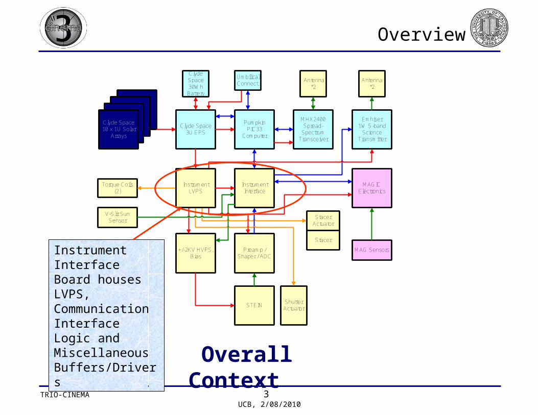
Overview
Clyde Space10 x 1U Solar
Arrays
Clyde Space3U EPS
PumpkinPIC33
Computer
MHX2400Spread-
SpectrumTransceiver
Antenna*2
InstrumentInterface
Emhiser1W S-band
ScienceTransmitter
Antenna*2
MAG Sensors
StacerActuator
Preamp /Shaper / ADC
STEIN
+/-2KV HVPS,Bias
ShutterActuator
Torque Coils(2)
V-Slit SunSensor
MAGICElectronics
ClydeSpace30Wh
Battery
UmbilicalConnect.
Stacer
InstrumentLVPS
Instrument Interface Board houses LVPS, Communication Interface Logic and Miscellaneous Buffers/Drivers
Overall Context

TRIO-CINEMA 4 UCB, 2/08/2010
Instrument Interface Board Block Diagram
IIF (Instrument Interface FPGA)
Transmitter Buffer
Emhiser Transmitter1Mbit/second digital data stream
Master Clock2^24
Sun Sensor Buffer
Pumpkin Processor(dsPIC33) SPI
I2C
STEIN DATA FIFO
MISC-I/O
TLMOUT
2 Sun Sensors (debounced in FPGA)
CDI Buffers
Data from STEIN
STEINCDI
Commands to STEIN
8.34MHz
MAG
ADC1216 operatedvia SPI Interface
SPIMISC-I/O (CS, RDY)
ADC-CLK (~4.2MHz)
REGISTERS andGeneral Control
Telemetry Framer~10MHz
500KHz
Torque Converter Drivers
PWM and Torquer Address
PWM signal steered to one of four torquersFrequency = 1KHz
Vin = ~8V 5V, 3.3V, 1.5VAnalog Supplies +/-5V, +/-12V, +20V
Switch/Actuator Control
LVPS Digital Supplies
Switches Torque Coil
MAG HVPS
Transmitter Actuator Ctl (some on STEIN?)

TRIO-CINEMA 5 UCB, 2/08/2010
Requirements
Level 1 Mission Assurance
MA-01 Mission Life 1 year +
Verification: Parts selection shall choose from ruggedized and historically rad-tolerant part types.
MA-02 Quality Use high quality commercial parts, space flight fabrication techniques. Utilize extensive testing to achieve reliability.
Cost
MA-03 Radiation Use rad tolerant parts where possible without significantly impacting cost. Consider spot shielding of critical parts with little shielding by the bus. Some form of solar cell protection (cover glass) probably required to meet mission life. Expected 1 year dose is 10krads behind 1mm Al, 3krads behind 2mm Al
Cost

TRIO-CINEMA 6 UCB, 2/08/2010
Requirements
Level 3 Sun Sensor (2x)
SUN-03 Interface
pull-up resistor, filter cap, discriminator on FPGA card; timing circuit on FPGA times rising edge, available to C&DH
Sensor Interface Requirement By Design/Inspection
Level 3 Torque Coils (2x)
TRQ-03 Interface
Bus power switches controlled by PWM on Instrument Interface Card. Switches may be on LVPS card or Instrument Interface Card (TBR)
Torque Coil Interface Requirement
IIB houses both LVPS and Torque Coil Drivers
Level 2 IIB (Instrument Interface and Power Board)
IIB-01 PrimaryPrimary voltage is ~8V bus voltage (7-9V, TBR)
IIB-02 Secondary
Provide +/-5V, +/-12V, +20V regulated secondaries (no primary ground isolation required) Currents TBD. Also +5VD, +3.3VD, +1.5VD [TBR}, some of which may be provided by EPS
Design/Test
IIB-03
Torque Coil Switches
Provide primary voltage switches controlled by 4 logic signals that allow you to power the two coils with either polarity.
Design/Test
IIB-04Other switches
Provide primary voltage switches for: MAGIC boom actuator, MAG 12V and 16V, STEIN actuators (2x), Transmitter, HVPS
Design/TestSTEIN Actuators (now on STEIN?)
IIB-05
STEIN Bias Supply
Provide programmable 0-150V bias supply. Supply must be very quiet but provides almost no DC load.
Design/Test (now on STEIN?)
TRIO-CINEMA 7 UCB, 2/08/2010
Requirements
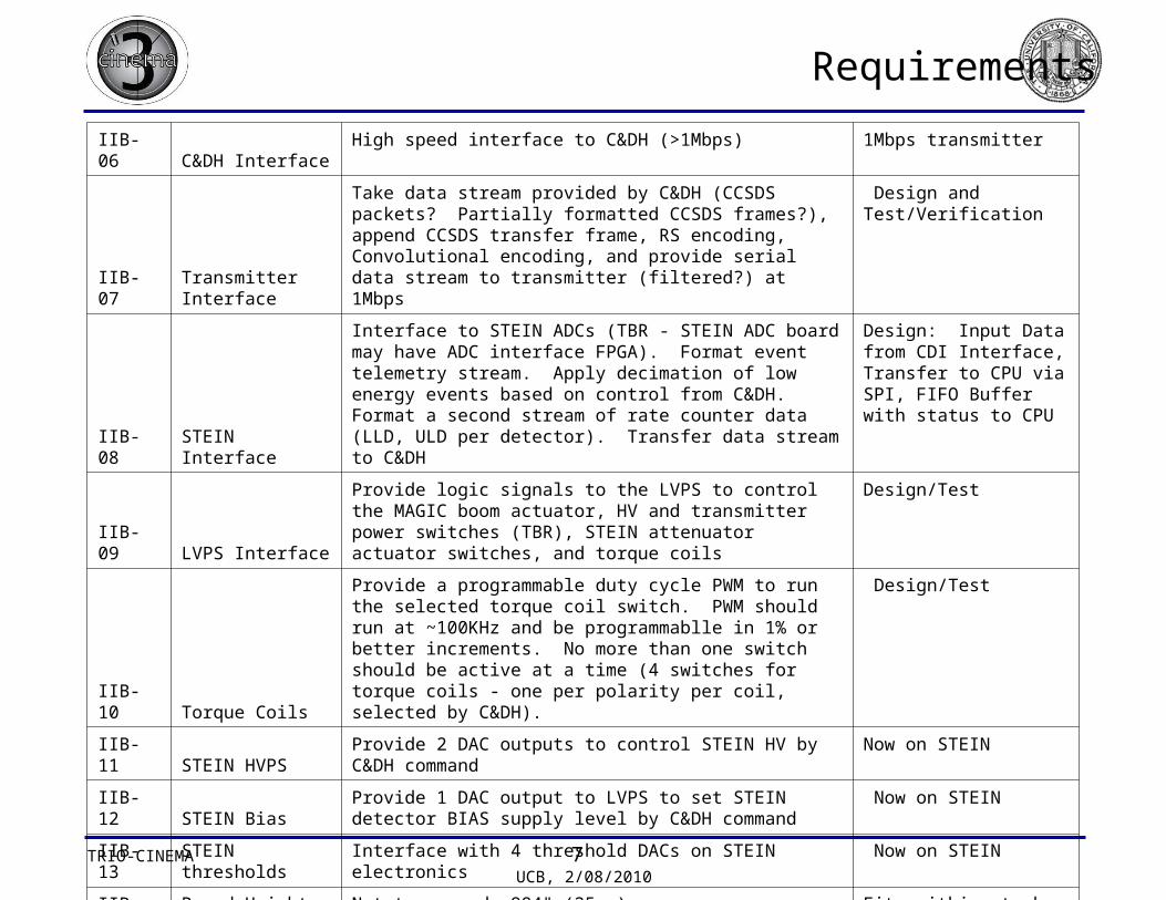
IIB-06 C&DH Interface High speed interface to C&DH (>1Mbps) 1Mbps transmitter
IIB-07Transmitter Interface
Take data stream provided by C&DH (CCSDS packets? Partially formatted CCSDS frames?), append CCSDS transfer frame, RS encoding, Convolutional encoding, and provide serial data stream to transmitter (filtered?) at 1Mbps
Design and Test/Verification
IIB-08 STEIN Interface
Interface to STEIN ADCs (TBR - STEIN ADC board may have ADC interface FPGA). Format event telemetry stream. Apply decimation of low energy events based on control from C&DH. Format a second stream of rate counter data (LLD, ULD per detector). Transfer data stream to C&DH
Design: Input Data from CDI Interface, Transfer to CPU via SPI, FIFO Buffer with status to CPU
IIB-09 LVPS Interface
Provide logic signals to the LVPS to control the MAGIC boom actuator, HV and transmitter power switches (TBR), STEIN attenuator actuator switches, and torque coils
Design/Test
IIB-10 Torque Coils
Provide a programmable duty cycle PWM to run the selected torque coil switch. PWM should run at ~100KHz and be programmablle in 1% or better increments. No more than one switch should be active at a time (4 switches for torque coils - one per polarity per coil, selected by C&DH).
Design/Test
IIB-11 STEIN HVPSProvide 2 DAC outputs to control STEIN HV by C&DH command
Now on STEIN
IIB-12 STEIN BiasProvide 1 DAC output to LVPS to set STEIN detector BIAS supply level by C&DH command
Now on STEIN
IIB-13 STEIN thresholds Interface with 4 threshold DACs on STEIN electronics Now on STEIN
IIB-14 Board Height Not to exceed .984" (25mm) Fits within stack
TRIO-CINEMA 8 UCB, 2/08/2010
Instrument Interface Board Components (1)
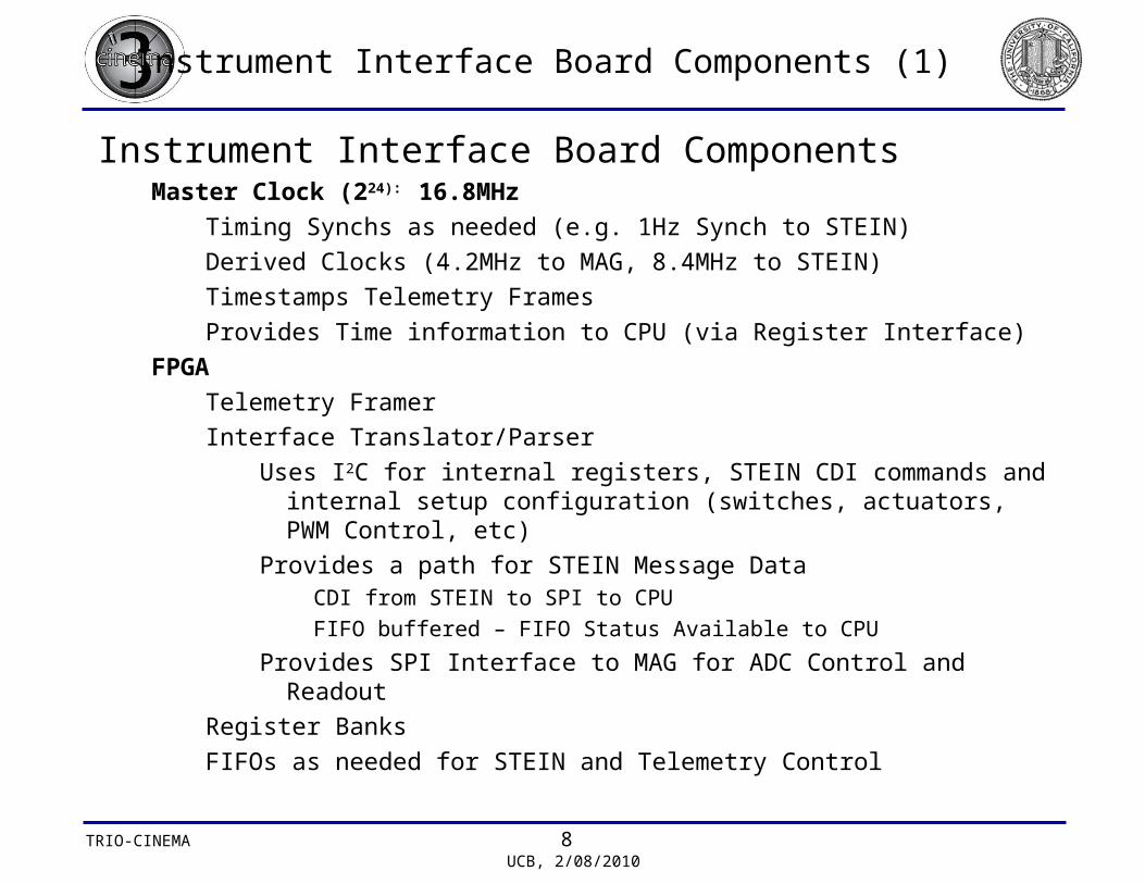
Instrument Interface Board ComponentsMaster Clock (224): 16.8MHz
Timing Synchs as needed (e.g. 1Hz Synch to STEIN)
Derived Clocks (4.2MHz to MAG, 8.4MHz to STEIN)
Timestamps Telemetry Frames
Provides Time information to CPU (via Register Interface)
FPGA
Telemetry Framer
Interface Translator/Parser
Uses I2C for internal registers, STEIN CDI commands and internal setup configuration (switches, actuators, PWM Control, etc)
Provides a path for STEIN Message Data CDI from STEIN to SPI to CPU
FIFO buffered – FIFO Status Available to CPU
Provides SPI Interface to MAG for ADC Control and Readout
Register Banks
FIFOs as needed for STEIN and Telemetry Control

TRIO-CINEMA 9 UCB, 2/08/2010
Instrument Interface Board Components (2)
Instrument Interface Board Components (continued)Specialized Buffers/Drivers
Actuators
Torque Drivers (4)
One PWM signal from FPGA is steered to one of four Torque Converters
Sun Sensor Receivers (2)
Open Collector Receiver with Pull-up and Filter Cap – Logic signal forwarded to the FPGA for further filtering
Switches
Torque Coil and Power, Actuator Switches, Emhiser Card, (others?)
Low Voltage Power SupplyReceive Primary Power (7-9 VDC)
Produce Secondary Voltages – use off the shelf regulators
+/-5V, +/-12V, +20V regulated secondaries (no primary ground isolation required), +5VD, +3.3VD, +1.5VD

TRIO-CINEMA 10 UCB, 2/08/2010
Data Rates
IIB/IIF is the Conduit Between the various CINEMA Subsystems– Must provide the 1Mbps continuous data stream to the S-Band transmitter
• Framing performed in hardware
• CPU provided fully formatted CCSDS packets via the SPI link
• Fill generated by hardware when no processor data is available
– SPI Data to/from CPU
• Used for S-Band Telemetry and STEIN Data (only one active at any one point in time)
• ~10MHz
– STEIN – CDI Message Interface
• 16 bits/event, 80KHz events = 1.28Mbps
• Interface bit rate = 8.4MHz, Data rate = 4Mbps (includes CDI Protocol and Message Tag Overhead, “fixed message size” mode)
– MAGIC Interface• 20 bits/sample x 20 samples/second x 3 axes = 0.001Mbps• I2C to/from CPU• SPI (resident in IIF) to/from MAG

TRIO-CINEMA 11 UCB, 2/08/2010
Development Plans
Development• Specification for FPGA (in progress, David Clarino)• Parts Selection and Overall Design
– Power Supply Modules– Custom Design as needed– Buffer, Switches and Driver circuits
• Board Schematic (not yet started)• CINEMA System Verification using Engineering Board• Flight Board (relayout if necessary) follows
test/verification• Load into Flight System • Joins CINEMA Test Flow and Quality reporting

TRIO-CINEMA 12 UCB, 2/08/2010
Issues
IIF/IIB
Some requirements are still TBD
Personnel for schematics and board layout


