READ THIS BOOK This operator’s book has important information for the use and safe operation of this machine. Read this book carefully before starting the machine. Keep this book and tell all operators to read the book. If you do not follow the instructions, you can cause an injury or dam- age equipment, furniture or buildings. For new books write to: Pacific 2259 South Sheridan Road Muskegon, MI 49442 Carefully inspect all components to ensure that there is no concealed freight damage. If such damage is dis- covered, file a “CONCEALED DAMAGE REPORT” im- mediately with the delivering carrier. The contents of this manual are based on the latest product information available at the time of publica- tion. Pacific reserves the right to make changes or improvements to its machines without notice. FOR YOUR CONVENIENCE, RECORD THE FOLLOWING IMPORTANT INFORMATION: MODEL_______________________________ SERIAL NUMBER______________________ PART NUMBER _________________________ DATE PURCHASED ____________________ OPERATING & MAINTENANCE INTRODUCTION INSTRUCTIONS TRIUMPH 1190 CARPET EXTRACTOR Parts Manual
Transcript
READ THIS BOOK
This operator’s book has important information for the
use and safe operation of this machine. Read this book
carefully before starting the machine. Keep this book
and tell all operators to read the book. If you do not
follow the instructions, you can cause an injury or dam-
age equipment, furniture or buildings.
For new books write to:
Pacific
2259 South Sheridan Road
Muskegon, MI 49442
Carefully inspect all components to ensure that there is
no concealed freight damage. If such damage is dis-
covered, file a “CONCEALED DAMAGE REPORT” im-
mediately with the delivering carrier.
The contents of this manual are based on the latest
product information available at the time of publica-
tion. Pacific reserves the right to make changes or
improvements to its machines without notice.
FOR YOUR CONVENIENCE, RECORD THE
FOLLOWING IMPORTANT INFORMATION:
MODEL_______________________________
SERIAL NUMBER______________________
PART NUMBER _________________________
DATE PURCHASED ____________________
OPERATING & MAINTENANCE
INTRODUCTION INSTRUCTIONS
TRIUMPH 1190
CARPET EXTRACTOR
Parts Manual
INTRODUCTION
The SELF CONTAINED EXTRACTOR is a fully self-contained, portable carpet extractor system and is intended for
commercial use. A wand with external vacuum and solution hoses are not necessary with your machine, but available.
The SELF CONTAINED EXTRACTOR has a 100 psi solution pump and a four (4) jet spraying system located on the
bottom side of the machine to apply solution to the carpet.
A rotating brush (16”) is driven by a cogged belt system at approximately 1200 RPM’s. This brush provides a very
aggressive agitation of the solution into the carpet fibers to loosen ground-in dirt. The chevron pattern of the brush
bristles channels the dirty water to the center of the aluminum vacuum head for better extraction.
The heavy duty three-stage vacuum motor is capable of 137 inches of water lift. Your SELF CONTAINED EXTRACTOR
extracts virtually all of the dirty solution from the carpet fibers, which dramatically reduces drying time.
The SELF CONTAINED EXTRACTOR is very “user friendly” machines. All controls are located at the top of the handle
grips, literally at your fingertips. The recovery tank drain valve is located high enough for the recovered solution to be
drained into a five (5) gallon bucket or bathroom toilet.
The SELF CONTAINED EXTRACTOR is balanced on large 10" diameter wheels for ease of operation and transporting.
The machines can be rotated 360° with relative ease, even when filled with solution.
The location of the wheel axle and the large diameter wheels allows for easy transporting up and down
steps when empty. It is not recommended these machines be transported up or down steps while contain-
ing any liquid in either the solution or recovery tanks.
This machine must be grounded. If it should malfunction or break
down, grounding provides a path of least resistance for electric
current to reduce the risk of electric shock. This machine is equipped
with a cord having an equipment-grounding conductor and ground-
ing plug. The plug must be inserted into an appropriate outlet that
is properly installed and grounded in accordance with all local
codes and ordinances.WARNING - Improper connection of the equipment-grounding con-
ductor can result in a risk of electric shock. Check with a qualified
electrician or service person if you are in doubt as to whether the
outlet is properly grounded. Do not modify the plug provided with
the machine - if it will not fit the outlet, have a proper outlet installed
by a qualified electrician.This machine is for use on a nominal 120-volt circuit, and has a
grounded plug that looks like the plug illustrated in figure A. A
temporary adapter that looks like the adapter illustrated in figures B
and C may be used to connect this plug to a 2-pole receptacle as
shown in figure B if a properly grounded outlet is not available.
The temporary adapter should be used only until a properly
grounded outlet (figure A) can be installed by a qualified electri-
cian. The green colored rigid ear, lug, or the like extending from the
adapter must be connected to a permanent ground such as a
properly grounded outlet box cover. Whenever the adapter is
used, it must be held in place by a metal screw.NOTE: In Canada, the use of a temporary adapter is not permitted
by the Canadian Electrical Code
EXTENSION CORDS
Use only three-wire 12/3 or larger gauge approved extension
cords that have three-prong grounding type plugs and three-pole
receptacles that accept the appliance’s plug. Replace or repair
any damaged cords or plugs.
When servicing, refer to authorized person only. Use only identi-
cal replacement parts.
Grounding Instructions
NOTE: Do not use adapters shown in figures B & C in Canada
2
IMPORTANT SAFETY INSTRUCTIONS
When using an electrical appliance, basic precautions should always be followed, including the following:
READ ALL INSTRUCTIONS BEFORE USING THIS MACHINE
WARNING: To reduce the risk of fire, electric shock, or injury:
1. You must have training in the operation of this machine before using it.
2. Machines can cause an explosion when near flammable materials and vapors. Do not use this machine with or
near fuels, grain dust, solvents, thinners, or other flammable materials.
3. Do not operate this machine unless it is completely assembled.
4. Do not use this unit for dry pick-up of dust or debris; Do not pick up anything that is burning or smoking, such as
cigarettes, matches or hot ashes.
5. To prevent electric shock, always remove the electrical plug from the electrical outlet before doing any repairs or
maintenance to this machine.
6. To prevent injury, always remove the electrical plug from the electrical outlet before leaving the machine.
7. Maintenance and repairs must be done by authorized personnel only.
8. Do not immerse. To reduce the risk of electrical shock, use only on carpet moistened by the cleaning process.
Protect the machine from rain. Keep the machine in a dry building. Always clean the machine with a clean dry
cloth.
9. Always use a three-wire electrical system connected to the electrical ground. For maximum protection against
electrical shock, use a circuit that is protected by a ground fault circuit interrupter. Consult your electrical
contractor.
10. To prevent damage to the power cord, do not move this machine over the power cord. Always lift the power cord
over the machine. Do not pull or carry cord, use cord as a handle, close a door on cord, or pull cord around sharp
edges or corners. Keep cord away from heated surfaces.
11. Make sure all switches are turned off before plugging or unplugging it power cord into/from a wall receptacle.
12. Do not use water that is hotter than 60°C (140°F).
13. To prevent damage to the solution system components do not store in freezing temperatures without proper
maintenance.
14. Do not allow to be used as a toy. Close attention is necessary when used near children.
15. Do not use with damaged cord or plug. If the machine is not working as it should, has been dropped, damaged,
left outdoors, or dropped into water, return it to a service center.
16. Do not unplug by pulling on cord. To unplug, grasp the plug, not the cord.
17. Do not handle the plug or machine with wet hands.
18. Do not put any object into openings. Do not use with any opening blocked. Keep free of dust, lint, hair and
anything that may reduce the airflow.
19. Keep hair, loose clothing, fingers and all parts of body away from openings and moving parts.
20. Use extra care when cleaning on stairs.
3
SAVE THESE INSTRUCTIONS
4
PREPARATION AND TRANSPORTATION
PRESTART-UP CHECKS
The SELF CONTAINED EXTRACTOR is very simple and easy to operate. Very little maintenance and service are
required to keep your machine in top operating condition.
The following procedures are recommended to maintain the high level of performance expected from your machine.
They are also intended to identify potential safety hazards and problems which could reduce the service life of the
machine.
READ BEFORE TRANSPORTING OR OPERATING YOUR MACHINE:
1. Check power cord, plug and strain relief for worn or damaged insulation. Repair or replace if necessary.
2. Make sure the drain valve is closed (T-Handle pushed down). If the valve is left open, the vacuum is dramatically
reduced and any recovered solution will drain out.
3. The knob for the spool valve is located on the lower back panel of the machine. During normal operation as a
self-contained extractor this knob is turned toward “machine” (horizontal position). It should be turned to the
“tool” position (vertical) when a wand or other tool is being used.1.
4. Lock the brush chassis in the up position for storage or transport. This is done by pulling up on the lift-handle
at the front of the machine, then resting the round lift stop behind the bracket.
5. Inspect the vacuum head and brush by tilting the machine backwards, allowing it to balance on the wheels and
drain valve spout.
a) Vacuum Head: Check for any damage. Burrs on the contact surface may snag carpet fibers. Gouges,
scratches and chipped areas can reduce vacuum performance.
b) Brush: Inspect for damaged or missing bristles, replace if necessary.
Return the machine to the upright position.6. Check the inlet strainer for damage or debris. It is located at the bottom of the fresh water tank. Holes in the
screen can allow contaminants to enter the pump resulting in costly repairs. A clogged strainer will reduce pump
performance and may cause permanent damage.
7. Remove the clear dome on top of the recovery tank.
a) Inspect for damage to the dome and gasket. Dirt or debris on the gasket or sealing surface of the tank
can cause a vacuum leak and reduce vacuum performance.
b) The intake filter screen at the vacuum hose connection should be clean of debris and checked periodi-
cally for any damage, replace if necessary.
c) Ensure that the deflector shield and intake filter are in their proper positions to prevent recovered
water from entering the vacuum motor (blower).
Return the cover to its original position with the front lip seated under the retaining bracket.
YOUR MACHINE IS NOW READY FOR OPERATION.
TRANSPORTING
The SELF CONTAINED EXTRACTOR is equipped with large diameter (10”) wheels for balance and ease of transport-
ing. It is designed to be tilted back on the wheels and pushed or pulled. The brush chassis should be locked in the
up position any time the machine is in storage or being transported.
The large diameter of the wheels permits you to pull the machine up stairs in the same manner you would use a hand
truck. Never go up or down stairs with recovered water or solution in the tanks. Always empty the machine
completely before transporting up or down stairs or in a vehicle.
When empty, the machine may be laid down on the side for transporting without damaging any of its components.
OPERATING PROCEDURES
5
The SELF CONTAINED EXTRACTOR is the most “user friendly” self-contained extractors available. The following
procedures are intended to describe and detail proper operation of your machine. Failure to follow these recom-
mended procedures can reduce the machine’s performance and may result in damage to the machine.
1. Vacuum the area to be cleaned. Your machine will do a more thorough job if the loose dirt and debris are
removed before the extraction process begins.
2. Fill the fresh water tank (lower tank) with water and Heavy Duty Carpet Extraction chemical. Hot water is
recommended, but not required. Do not use water hotter than 60°C (140°F). Mix in chemicals according to the
chemical manufacturer’s recommendations.
3. Use of an extension cord is not recommended. However, if one is necessary, use only a 14 gauge or larger cord.
Smaller or inferior cords are dangerous and may cause damage to your machine.
4. After the machine is filled with solution, connect the power cord plug to a 115 volt grounded wall socket.
See Grounding Instructions.
5. Lower the floating brush chassis using the lift handle located in the front of the machine. Lift the handle off the
lift stop bracket and lower until the brush contacts the floor. Remember to always raise and lock the brush
chassis for storage and transport.
6. Turn the spool valve knob (located on the back of the machine) to the:
a) “Machine” (horizontal) position for routine carpet extraction as a self-contained unit, or
b) Turn it in the “Tool” (vertical) position when using a wand or tool.
7. The switch panel is located on top of the handle and contains the following:
a) Turn the vacuum switch on to start the vacuum motor.
b) Accessory only pump switch: Do not turn on the accessory pump switch unless the spool valve knob is
turned to the tool position.8. Pull backward during operation. DO NOT ATTEMPT TO OPERATE IN A FORWARD DIRECTION. Position
yourself behind the machine, grasp the handle and gently lift up on the actuator bar. Lifting the actuator bar
activates the brush drive motor and the pump. Walk slowly backward to perform the cleaning process.
9. Release the actuator bar approximately 6 inches before completing each pass. The spray jets are located
behind the vacuum head making it necessary to pull the machine a few inches further to pick up the last amount of
solution dispensed onto the carpet.
10. Tilt the machine back on the rear wheels and walk forward to position the machine along side the previous
pass (slightly overlapping).
11. As dirty solution is recovered, some foaming may be noted. Excessive foaming can be counteracted with liquid
defoamer applied according to the chemical manufacturing directions. Do not allow foam to rise into or near the
dome. Use defoamer or empty and flush the recovery tank.
12. To drain the recovery tank, place an empty bucket under the drain valve located on back of the machine. To open
the drain valve pull the T-Handle up. Close the drain when the bucket is full or the recovery tank is empty. Dispose of
the recovered water properly.
13. If streaking occurs after a period of operating time, this means the solution (fresh water) tank is near empty.
Streaking is eliminated by adding more water and chemical solution to the tank.
14. To drain the solution tank, attach the small drain or “pump out” hose to the accessory quick connect on the back
of the machine. Turn the spool valve knob to the “tool” position. Place the open end of the hose into a bucket and turn
on the accessory pump switch. When empty, turn off the pump switch and remove the hose from the quick connect.
Also return the spool valve knob to the “machine” position.
15. After each use clean the dome, intake filter and gasket. Do not reinstall the dome until the next use, this will
allow the recovery tank to dry out.
16. Raise the brush chassis for storage.
6
SERVICING
The SELF CONTAINED EXTRACTOR is designed and manufactured to provide years of trouble free service with a
minimum of maintenance and service. The following recommendations are intended to assist the operator and Service
Technician in performing routine maintenance.
Failure to follow these recommendations can result in damage to your machine and diminished performance.
Warning: Always unplug your machine before performing any service. Severe personal injury could result
if the electrical power is not disconnected.
1. Always follow through with the recommended prestart-up checks found in the Preparation and Transportation
section of this manual.
2. Store your machine in a dry, protected area with the brush chassis raised and locked in place. Do not expose this
machine to rain, standing water or freezing temperatures.
3. We recommend a good, thorough cleaning after each use. Clean the dome top, intake filter screen and recovery
tank with fresh, clean water. Flush the fresh water tank and strainer periodically with clean water.4. After continuous or repeated use, the jet tips and strainer/check valves will need cleaning. Unplug the cord and
empty the recovery and solution tanks. Tilt the machine backward allowing it to balance on the wheels and drain
valve. Remove the jet caps shown in the brush chassis illustration and clean with white vinegar and a soft bristle
brush. Remove the jet tip and strainer/check valve and soak it in vinegar until visible deposits are dissolved, then
scrub with a soft bristle brush.
Jet tips and strainer/check valves should be replaced once a year because they tend to erode under extended
use. This can cause overuse of solution and possible streaking.
AN AUTHORIZED SERVICE CENTER SHOULD PERFORM THE FOLLOWING PROCEDURES
1. Drive Belt Adjustment and/or Replacement: The cogged drive belt system rarely needs tightening, so if
it becomes loose from wear, it is time to replace it. Follow this procedure:
a) Remove the two screws that attach the hanger bracket to the brush shroud. Then remove the thru-bolt from
the brush chassis and lift handle. Remove the lift handle and lift stop.
b) Tilt the machine backward allowing it to balance on the wheels and drain valve. The brush chassis will remain
on the floor exposing the brush drive belt and motor.
c) Loosen the two motor bracket mounting bracket mounting bolts with a 7/16” wrench. DO NOT REMOVE THE
BOLTS UNLESS YOU ARE REPLACING THE MOTOR. Slide the motor away from the brush to tighten the
belt or toward the brush for removal.
Unlike a “V” type belt, the cogged belt is run with basically zero deflection. To test the belt tension, hold
the belt between your thumb and forefinger and twist to the side. It should turn approximately 90° with little
effort. If it twists more than 90°, retighten the belt.
2. Pump Replacement:
a) Remove the lift stop handle as described in the “Belt Drive” procedure (#1a).
b) Tilt the machine backward as described in the “Belt Drive” procedure (#1b)
c) Disconnect black wire (#2) and the white wire from the bridge rectifier (part #A130172). Also disconnect the
ground wire (this will need to be respliced and reconnected to the ground wire on the brush motor when
reassembling). Reference the electrical schematic.
d) Remove the two hoses from the pump. It is now fully exposed for replacement.
e) When reassembling after any repairs, make certain that all wire connections are properly plugged in and
secure.
f) Make all solution hose connections secure.
7
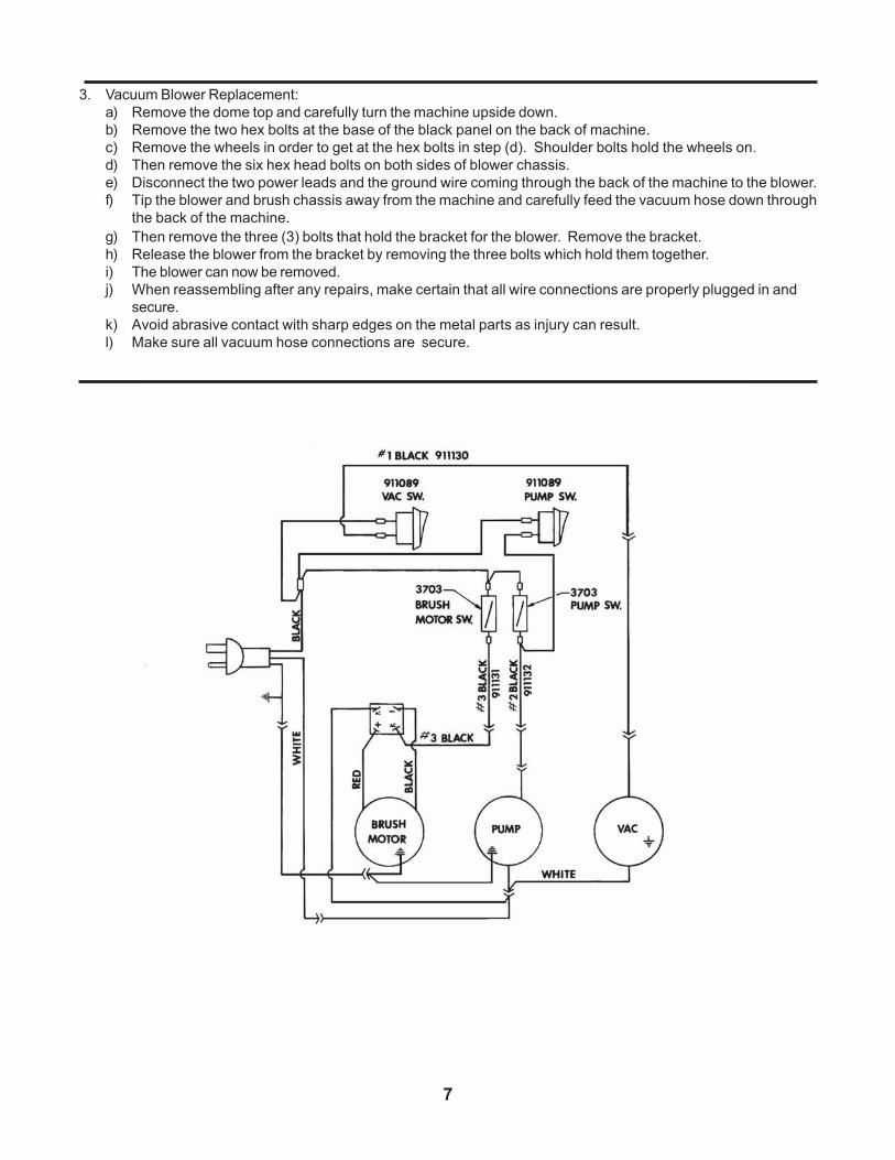
3. Vacuum Blower Replacement:
a) Remove the dome top and carefully turn the machine upside down.
b) Remove the two hex bolts at the base of the black panel on the back of machine.
c) Remove the wheels in order to get at the hex bolts in step (d). Shoulder bolts hold the wheels on.
d) Then remove the six hex head bolts on both sides of blower chassis.
e) Disconnect the two power leads and the ground wire coming through the back of the machine to the blower.
f) Tip the blower and brush chassis away from the machine and carefully feed the vacuum hose down through
the back of the machine.
g) Then remove the three (3) bolts that hold the bracket for the blower. Remove the bracket.
h) Release the blower from the bracket by removing the three bolts which hold them together.
i) The blower can now be removed.
j) When reassembling after any repairs, make certain that all wire connections are properly plugged in and
secure.
k) Avoid abrasive contact with sharp edges on the metal parts as injury can result.
l) Make sure all vacuum hose connections are secure.
TANK & BLOWER ASSEMBLY
8
5
TANK & BLOWER ASSEMBLY PARTS LIST
9
ITEM PART NO. DESCRIPTION QTY. ITEM PART NO. DESCRIPTION QTY.