87


Triumph Register of AmericaFormed to Preserve the Marque TR-2/3/3A/3B
Judging Standards and
Restoration Guidelines
February 1993 EditionMay 2004 Revision
Reproduction of This Document. Triumph Register of America permits individuals or groups to reproduceportions this document for nonprofit use with the sole requirement of acknowledgement of the source, TRA.
While TRA's objective is to provide membership with most complete and accurate restoration information,TRA makes no warranty or guarantee, either express or implied, on the information contained within andwill not be held liable for inaccuracies, notification of changes, or omissions.

T R A
2
Table of Contents
Introduction 3
Acknowledgments 4
Revision History 4
References 4
General Rules for Concours 5
Exterior EX-1
Underhood UH-1
Interior IN-1
Chassis CH-1
Appendices
Master Scoring Sheet A
TR2/3/3A Paint and Trim Materials B

T R A
3
Introduction
THE TRIUMPH REGISTER OF AMERICA, the only national U.S.A. organization devoted solely to the TR-2/3series, provides this document not only for use as a guide for concours judging but also as a guide for members touse during restoration.
Concours de Elegance has been a highlight of TRA national meets for nearly twenty years. TRA has made thisactivity a priority because we feel that it is critical to preserving the marque. Concours provides a way for membersto receive recognition for their restoration and preservation investment. It also provides a model and stimulus forthose considering or in the process of restoration.
About TRA. TRA is a nonprofit organization established to aid TR-2/3 owners in the preservation, maintenanceand enjoyment of their classic sports cars and is concerned with establishing local groups of TR-2/3 owners. Localused parts supply networks and local activities such as technical workshops and rallies provide the binding glue forour national organization.
About Concours. Concours is for the enthusiast who takes pride and satisfaction in his/her car. To compete inconcours requires substantial investments of time and money. As such, it is usually taken very seriously by theparticipants. To successfully conduct a concours event also requires a substantial investment in preparation. To besuccessful, the concours event must have the following goals:
* Accuracy -- The evaluation of a car's originality is accurate and the evaluation of the quality of thecar presented is fairly decided.
* Consistency Across the Event -- Participants should feel that their car is judged consistently withothers and agree with their score relative to others.
* Consistency From Event to Event -- Assuming that a car is shown in two successive events, thejudging process, regardless of whether the judges are the same, should result in a comparablescore.
* Timeliness -- Practically, concours judging can take at most two or three hours. Therefore,judging must balance thoroughness with speed of operation.
To attain these goals requires dedication in the organization to develop standards, to seek out and train qualifiedjudges, and to continually review and re-evaluate the entire process.
About This Document. This guide is to serve as reference for judges in TRA concours events and for TRAmembers doing restorations. The material presented is the result of several years of work, assembling informationfrom factory reference material, TRA members expertise, TRA judging school reviews and presentations, and otherTriumph history material.
Accuracy of Information. In each section of the guide, you will find specific cautions about the accuracy of theinformation provided. While the contributors have spent hundreds of hours researching reference material, theinformation available is often lacking thorough documentation. In addition, there is a significant margin of error inthe information that results from the mass production process used in TR assembly. For example, there are severalcases where the parts manual indicates a change at a particular commission number but the change actually tookplace over several weeks of production such that any given car produced during that time might have the early orlate component/configuration. While the authors provide indications of confidence in the information whereappropriate, in general, if your car does not match a specification provided, do not immediately conclude the car isin error; research the subject further yourself or consult local experts before making changes.

T R A
4
Acknowledgements.
1977 TRA Concours Scoring Sheets (with judging guides incorporated) -- Skip Marsh and Ron Gordon(PACTRA,Mason Dixon/TRA)
Circa 1983 TRA Concours Judging Guide -- Dave Hannah (COCTRA)1990 TRA Underhood Judging School (Video) -- Conducted by Tom Householder (COCTRA).1991 TRA Interior Judging School -- Conducted by John Warfield (Mason Dixon/TRA)
Authors: John Gabel (COCTRA), Joe Richards (COCTRA), and John Warfield (Mason Dixon/TRA).
Other principal contributors listed in individual sections.
Other Acknowledgements: Many have contributed to this effort and we expect will continue in the future. Ofparticular note are the judges at TRA National Meets. Pre-judging reviews and post-judging debriefs have providedexcellent feedback on the materials and direction for extensions. Judging Schools held at the TRA National Meeteach year have also provided excellent feedback and input to the material. Walk-arounds during the schools haveraised dozens of questions which we've tried to address within. Reviews of new material with other members incenters across the country have been very productive; these have helped fill in holes, find new holes, and in generalprovided excellent inputs to the development of the material. We also have held "dry-runs" of new judgingguidelines on different occasions, COCTRA members have "volunteered" to be test judges on local cars to see howlong it takes, how easy the materials were to use; how consistently different judges scored. These dry-runs haveyielded insights into what is practical for judges to use and resulted in many adjustments. TRA membership ingeneral have contributed with calls or letters with information, suggestions, and corrections to the guide over thelast few years. We also need to mention the vendors. In addition to allowing us to copy some of their artwork, TheRoadster Factory has provided a wealth of reference material in catalogs and newsletters from which variousinsights into the Stanpart catalogs were obtained. Moss Motors catalogs and a variety of other vendors' materialhave also been useful resources. For example, Joe had a summary of TR heads from a Moss Motors catalog tackedto a wall in his barn which we found to be a great reference; who knows how old and what issue the catalog was itcame from, but it raised the right questions and we later found suitable documentation. Many thanks to all...
Revision History.
June 1989 Edition -- Initial version, Exterior.June 1990 Edition -- Minor Revisions to Exterior; initial portion of Underhood added..June 1991 Edition -- Underhood sections added: Identification Plates, Electrics, Hydraulics; Interior
added; minor edits and corrections to other sections.May 1992 Edition -- Added Underhood sections on Engine, Fuel System, Controls, Cooling system.
Minor corrections and edits to other sections. February 1993 -- Chassis section added; change to 100 point scoring in Exterior and Interior sections;
rework of introductory material; some extensions in Interior.March 1995 - Interior Deduction Guide is incorporated into Scoresheet. Scoresheet re-organized
to facilitate judging. Handbook and Coach Key added to required items results in minorreallocation of points for tools. Other minor additions and clarifications.
May 2000 – Underhood: minor edits, extension; replacement of “Underhood Scoresheet andOriginality Deduction Guide” with redesigned scoresheet which includes deduction guidelines.
May 2004 – All scoresheets upgraded to current format.
References.
References are provided at the beginning of the individual sections.

T R A
5
General Rules for Concours
Scope. Judging is based on:
Quality of Restoration -- The condition of the various components.
Originality -- The components presented match those specified for the model and commissionnumber.
Scoring. In general, points are earned for quality and points are deducted for originality deviations. Scoring isdone independently for the four judging areas: Exterior, Underhood, Interior, and Chassis. Historically TRA hasgenerally used a 100 point scheme with the following allocations to judging areas:
Judging Area Allocation
Exterior 40 pointsInterior 25 pointsUnderhood 20 pointsChassis 15 points
Weighted Scoring. TRA has experimented with a variety of scoring schemes. For many years, the points allocatedto each judging area were used with no weighting. So, for example, the Underhood judges had 20 points to workwith. Since Underhood has dozens of components, the few number of points made scoring difficult for judges;deductions in fractions of points resulted and often this was inconsistently done across judges, especially from oneyear to the next. As a result we have adopted a 100 point scheme for each judging area and map the area scoresinto a total of 100 points based on the allocations listed above. For example, if a car is given full 100 points forUnderhood, then the 100 points is multiplied by 0.20 (resulting in 20 points) on the Master Scoresheet for the actualUnderhood contribution to the total score for the car.
Component Allocations within Judging Area. Within each judging area, detailed breakdowns of components andtheir point allocations are provided to improve judging consistency and reduce bias of individual judges from yearto year. For example, in Underhood, Hydraulics is allocated 10 points (of 100 total for Underhood). At most then,the judge can deduct 10 points for Hydraulics.
Deduction Guides. The current judging materials are designed to give more explicit guidelines for determiningscores by giving specific deductions for particular originality deviations. Again, the objective is to improveconsistency. In Underhood for example, specific originality deductions are listed for Hydraulics; these deductionsare made independent of the quality of the presentation.
Scoresheets. Scoring is recorded on scoresheets for each judging area and the totals then recorded on a MasterScoresheet for each car. Scoresheets used include:
* Exterior Scoresheet -- This is used for scoring body originality, miscellaneous exteriorcomponents quality and originality, and the total Exterior score.
* Exterior Scoring, Bodywork and Paint Worksheet --This supplemental scoresheet is providedfor the evaluation of the quality of bodywork and paint.

T R A
6
* Underhood Scoresheet -- This is used for scoring quality and originality of the enginecompartment, including the firewall and inner fenders.
* Interior Scoresheet -- This is used for scoring the interior of the passenger compartment, the topand the trunk area, including tool kit.
* Chassis Scoresheet -- This covers the frame, suspension, exhaust, and wheels.
* Master Scoresheet -- This is used to collect the individual scoresheet subtotals and to calculate atotal score.
The area scoresheets are included in the corresponding sections of this document. The Master Scoresheet isincluded in Appendix A.
Rules for Concours Participants.
* Drive onto field -- In order to participate in concours, the car must be driven onto the concoursfield.
* Top in place -- Top is presented on the car. Any car presented without top will lose all pointsfor top.
* Sidecurtains -- Sidecurtains are to be displayed, normally at the rear of the car. If threateningrain, the Head Judge may permit sidecurtains to be displayed in place.
* Trunk -- Access is needed to the trunk area by Interior judges. The jack and tool kit is to bedisplayed within. Personal articles are to be removed.
* Judges access to car -- In order to conduct judging, hood and trunk must be raised and closedand doors must be opened and closed. If the owner wishes to remain with the car, they may dothis themselves. If not present, implicit permission is given to judges to open and close doors,hood or trunk. The judges will not make any effort to find an owner who is not present whenthe car is judged.
* Interaction with Judges -- Except for interaction related to opening and closing, no interactionwith judges is allowed while judging. Questions and comments should be raised with the HeadJudge.
Rules for Judges.
* Contact with Car -- Judges should avoid contact with the car surfaces and components. Theexception is with Interior judges; they must be allowed access inside the car and contact withthe car is unavoidable.
* Interaction with Participants -- The only interaction that the judging team should have with theowner is to ask the owner to open and close doors, hood, or trunk. If the owner is not present,the crew is given implicit permission to open and close doors, hood, and trunk as needed.
* Contact with Spectators -- Judges should avoid any discussions while judging. If askedquestions, they should refer the individual to the Head Judge or suggest a discussion afterwards.

T R A
7
Judging Teams. Given the detail of scoring that TRA uses, the volume of cars influences the number of judgesneeded and their coverage of cars. We have found using the same judges for a particular judging area across allmodels is best approach. We also employ multiple judging crews for Exterior and Underhood. Breaking theExterior and Underhood teams into crews with specialties is done to allow the same individuals to judge all cars andto limit the responsibilities of individual judges.
Selection of judging teams follows these guidelines:
* Attendance at 2 Judging Schools -- Regardless of whether the topics covered in the schools were on thearea to be judged, we want judges who not only have shown interest in judging but also have beenexposed to the judging material.
* Encourage Prospective Judges to Participate as Assistants -- We like to have assistants assigned tojudging crews to help take down scores and comments. Being an assistant allows a prospective judge tosee what is involved and get a better feel for what is required.
* Mix Experienced Judges with New Judges.-- We like to pair up an experienced judge with a first-timejudge. This helps provide consistency from year to year. It also helps to encourage prospective judgesto volunteer who are a bit nervous about jumping in.
* Demonstrated Knowledge of the Area -- From conversations during judging schools, references fromother members, or other means, we try to pick people for judging who are knowledgeable of the cars andrestoration in general. "Knowledgeable" does not mean the person must be an authority or expert. Beingan expert, does not mean a person will make a good judge; not being an expert does not mean a personwon't make an outstanding judge either.
Official Scorer. All judging scoresheets are returned to the Official Scorer. The Official Scorer checks thearithmetic of the individual scoresheets, in some cases may calculate the scoresheet total scores, and transcribes theindividual scoresheet totals to the Master Scoresheet. The scorer will later provide copies of the completed scoringsheets to presenters, on request, assuming that this is practical to do.
Head Judge. The Head Judge assigns judges, insures that concours rules for participants are communicated,resolves any questions or differences between judges, and monitors judging and scoring. In addition, participantswith questions or problems with the judging process or scoring of his/her car should address such with the HeadJudge.

Exterior
Table of Contents.
Introduction 2Acknowledgements 2Revision History 2References 2
Exterior Judging. 3Exterior Scoresheet 4Exterior Scoring, Bodywork and Paint Worksheet 5
Quality of Restoration Judging Bodywork 6Paint 7Body Panel Evaluation Guide. 8
Originality Judging 9Front Apron 10Badge and Letters 11Hood, Trunk, and Doors 12Rear Apron 13Miscellaneous Exterior Evaluations 14

T R A
EX-2
Exterior - Introduction
This guide is intended to serve as reference for judges in TRA concours events and for TRA members doingrestorations. The material presented is the result several years of assembling information from factory referencematerial, TRA members expertise, TRA judging school reviews and comments, and other Triumph history andreference material.
Acknowledgements.
Authors and principal contributors: Joe Richards and John Gabel (COCTRA).
Revision History.
June 1989 - Initial version.June 1990 - Minor edits and corrections.February 1993 - Organizational changes; change from 40 to 100 point scoresheets.
References.
The following are referenced where appropriate within "Exterior". The abbreviations enclosed in parens are used toidentifythe associated reference.
(SPCEd1) Triumph Sports Car Spare Parts Catalogue, Edition 1. Part No. 501653/USA.(SPCEd2) Triumph Sports Car Spare Parts Catalogue, Edition 2. Part No. 501653/USA. (SPCEd3) Triumph Sports Car Spare Parts Catalogue, Edition 3. Part No. 501653/USA. (SPCEd4) Triumph Sports Car Spare Parts Catalogue, Edition 4. Part No. 501653/USA. (HWC) Stanpart Hardware Catalogue for use with Standard Triumph Vehicles. Publication part
number 514264.
T R A
EX-3
Exterior Judging
Scope. Exterior judging covers the car body panels, windshield, lights, bumpers, and other objects mounted on thecar exterior. Judging is based on:
Quality of Restoration -- The condition of the various components.
Originality -- The components presented match those specified for the model and commission number
Scoring. In general, points are earned for quality and points are deducted for originality deviations. Scoring isrecorded on the Exterior Scoresheet. In addition, a supplemental scoresheet, Exterior Scoring, Bodywork and PaintWorksheet, is provided for the evaluation of the quality of bodywork and paint. Both sheets will be returned to theOfficial Scorer.
Exterior Scoresheet -- Has two sections:
* Body Panels. Body panels are judged for quality and originality. Quality points areearned(subtotal obtained from the worksheet) by panel and subtotaled. From thesubtotal,deductions are made for originality deviations. Originality judging reference material isprovided for each major area of the exterior including variations in the models.
* Miscellaneous Exterior. Major, non-sheet metal, items on the exterior are evaluated for qualityand originality. Scoring for each item is detailed on the scoresheet. Guidelines for evaluationof quality and originality are provided in the section Miscellaneous Exterior Evaluations.
Exterior Scoring, Bodywork and Paint Worksheet -- This worksheet includes a diagram of the sheet metal and ascoring table. The judges will annotate flaws observed on the diagram for their own use and and for the ownersreference. They will convert the observations into scores for individual panel types. Scores per panel are brokeninto three categories: Bodywork, Paint, and Mountings. Mountings include items that are "mounted" on the panels,like door handle and trunk securing mechanisms. The maximum points that can be given in a category and across apanel is included in the table. General bodywork and paint evaluation guidelines are provided in supplementalmaterial. Included in the support material is a Body Panel Evaluation Guide which lists particular areas to bechecked on each panel.
Car Inspection Requirements. Quality of resotration must be judged with the Trunk and Hood in the closedposition.
TRA
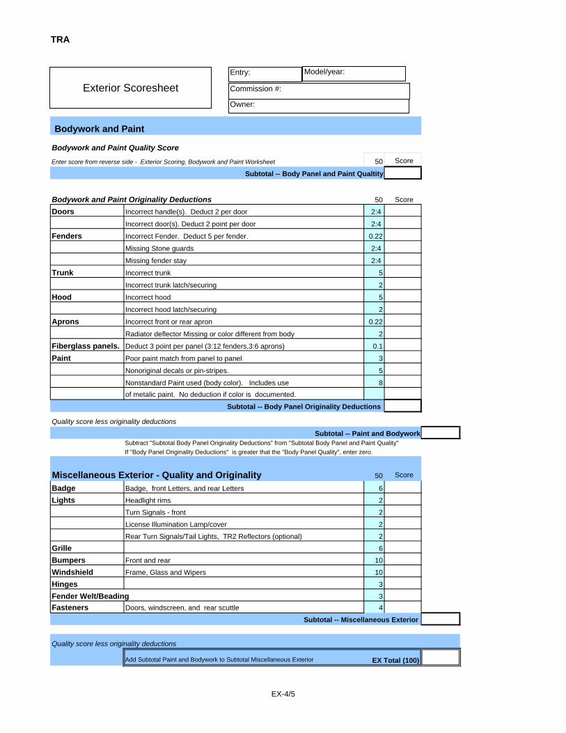
Bodywork and Paint
Bodywork and Paint Quality Score Enter score from reverse side - Exterior Scoring, Bodywork and Paint Worksheet 50 Score
Subtotal -- Body Panel and Paint Qualtity
Bodywork and Paint Originality Deductions 50 Score
Doors Incorrect handle(s). Deduct 2 per door 2:4
Incorrect door(s). Deduct 2 point per door 2:4
Fenders Incorrect Fender. Deduct 5 per fender. 0.22
Missing Stone guards 2:4
Missing fender stay 2:4
Trunk Incorrect trunk 5
Incorrect trunk latch/securing 2
Hood Incorrect hood 5
Incorrect hood latch/securing 2
Aprons Incorrect front or rear apron 0.22
Radiator deflector Missing or color different from body 2
Fiberglass panels. Deduct 3 point per panel (3:12 fenders,3:6 aprons) 0.1
Paint Poor paint match from panel to panel 3
Nonoriginal decals or pin-stripes. 5
Nonstandard Paint used (body color). Includes use 8of metalic paint. No deduction if color is documented.
Subtotal -- Body Panel Originality Deductions
Quality score less originality deductionsSubtotal -- Paint and Bodywork
Subtract "Subtotal Body Panel Originality Deductions" from "Subtotal Body Panel and Paint Quality"If "Body Panel Originality Deductions" is greater that the "Body Panel Quality", enter zero.
Miscellaneous Exterior - Quality and Originality 50 Score
Badge Badge, front Letters, and rear Letters 6
Lights Headlight rims 2
Turn Signals - front 2
License Illumination Lamp/cover 2
Rear Turn Signals/Tail Lights, TR2 Reflectors (optional) 2
Grille 6
Bumpers Front and rear 10
Windshield Frame, Glass and Wipers 10
Hinges 3
Fender Welt/Beading 3Fasteners Doors, windscreen, and rear scuttle 4
Subtotal -- Miscellaneous Exterior
Quality score less originality deductions
Add Subtotal Paint and Bodywork to Subtotal Miscellaneous Exterior EX Total (100)
Exterior ScoresheetEntry:
Commission #:
Owner:
Model/year:
EX-4/5

TRA
Bodywork and Paint Worksheet
Annotations:X Bodywork flaw VVV Paint flaw// Alignment flaw
Major flaws circled.
Quality of Restoration ScoringBodywork Paint Mountings Subtotal
Doors & Rockers 4 2 2 8Fenders 8 6 2 16Trunk 3 3 2 8Hood 3 3 2 8Aprons 5 3 2 10
Subtotal 23 17 10 50
Subtotal -- Body Panel and Paint Qualtity
EX-4/5

T R A
EX-6
Bodywork - Judging Quality of Restoration
Scope. Bodywork inspection should concentrate on the condition of panels and should not include consideration ofthe surface paint condition. Rust or damage affecting panel condition and paint condition may be considered inboth bodywork and paint quality. Originality Deductions should not affect point earnings here.
Scoring. Points are earned in increments of whole points. For example, a 2 point allocation can be scored as 0, 1,or 2 points. The lowest possible score per panel category is zero; negative scores are not permitted. See pointallocations possible by panel on Exterior Scoring sheet.
Points Earned..... Evaluation.....
Maximum Points * All surfaces smooth, free of signs of repair, and well aligned.Partial * Surfaces in good condition with some minor flaws: visible signs of repair, lack
of repair, or misalignment.No Points * Numerous minor flaws: neglected repairs or consistently poor workmanship.
Multi-panel Scoring. In the case of fenders, and other multi-panel categories, point allocations should bedistributed evenly between the individual panels and each panel judged independently. For example, if three offour fenders are in excellent shape and the fourth is in poor shape, the three good fenders should earn 3/4ths of theallocation .
Inspection --
The inspection should include but is not limited to the following areas:
Presentation..... Flaws.....
Contours * Waves due to sandblasting, collision* Bulges due to collision or misalignment.* Body filler does not restore original surface contour resulting in high, low orbumpy areas.
Fine work * Edges of repair are not feathered, softened adequately.* Sanding marks showing thru paint.
Attention to problems * Repairs not performed: dents, dings, or rust have not been repaired.Alignment * Panel lines out of alignment with tub or other panels.
Caution: Avoid reducing score on two different panels for alignment problems: eg., don't reduce fender and hoodscores if fender-hood alignment is not uniform. The Body Panel Evaluation Guide section attempts to organizeevaluation items of this sort so that this will not be a problem.
Reference Body Panel Evaluation Guidelines below (pg EX-8) which lists by panel specific areas that should bechecked.

T R A
EX-7
Paint - Judging Quality of Restoration
Scope. Paint inspection should concentrate on the condition of surface paint and should not include considerationof the underlying bodywork. Rust or damage affecting panel condition and paint condition may be considered inboth bodywork and paint quality. Evaluation is to based on paint presented, by panel; Originality Deductionsshould not affect point earnings here.
Scoring. Points are earned in increments of whole points. For example, a 2 point allocation can be scored as 0, 1,or 2 points. The lowest possible score per panel category is zero; negative scores are not permitted. See pointallocations possible by panel on Exterior Scoring sheet.
Points Earned..... Evaluation...
Maximum Points * Surfaces beautifully prepared, in excellent condition.Partial Points * Good general appearance with 1 or 2 obvious flaws.No Points * Numerous minor flaws: neglected repairs or consistently poor
workmanship.
Multi-panel Scoring. In the case of fenders, and other multi-panel categories, point allocations should bedistributed evenly between the individual panels and each panel judged independently. For example, if three offour fenders are in excellent shape and the fourth is in poor shape, the three good fenders should earn 3/4ths of theallocation .
Inspection --
The inspection should include but is not limited to the following areas:
Presentation..... Flaws.....
Smoothness * Rough from overspray, dry paint, checking, dirt, cracking.Even application * Runs, sags, visible touch-up layers or spot rings.Color consistency * Light spots to uneven application, blending problems, moisture control.Clarity * Orange peel, fish-eyes, water spots.Luster * Hazy, dull areas due to application or lack of necessary post-paint rub-out.Wear * Chips or scratches.
Reference Body Panel Evaluation Guidelines (pg EX-8) which lists by panel specific areas that should be checked.

T R A
EX-8
Body Panel Evaluation GuidelinesQuality of Restoration
Scope: The following is provided to assist Body Panel, Quality of Restoration, judging. Originality judging is notincluded. This information supplements panel evaluation described in the sections: Bodywork - Judging Quality ofRestoration and Paint - Judging Quality of Restoration.
Doors and Rockers Bodywork - Short door models should have a visible vertical seam at rear of rockers.
Alignment - Uniform gap between door and fenders, rocker, and scuttle- Door skin flush with fenders, rocker, and scuttle.
Paint - No rings around fasteners due to over-tightening.- No marred paint resulting from installation.
Mountings- Handles - At rest are parallel to ground. Chrome in good repair.- Lock Assembly - Body latch chromed, clean.
- No signs of misalignment wear on body or door assemblies.- Door Stop - Hex machine screw used in hinge.
Fenders (and Dog Legs)Bodywork - Fender well is straight from front to back.
(Common problem is buldge toward top of wheel well).Alignment - Rear fender beading/welt curves evenly toward tail light.
- Front fender beading/welt is straight from front to back.- Wings aligned evenly with body tub.
Mountings - Rear light is mounted squarely on fender and rear apron.- Stone guards fit tightly against body and in good repair. - Rear wing has stay just behind rear wheel.
Trunk (and Rear Scuttle)Bodywork - Look for problems resulting from stress (or attempted repair) in hinge corners
where corners of trunk often are bent up slightly.- Look for poor repairs along edge with apron, where alignment problems with apron might be made.
Alignment - Uniform gap between fenders, apron, and scuttle.- Surface flush with fenders, apron, and scuttle surfaces.
Mountings - Gas cap, lock, lugauge rack and escutcheons (if applicable) condition. - Handled lock should point down at rest.
Hood (and Front Scuttle)Bodywork - Surface has little contour (flat basically) and is prone to waves.Alignment - Uniform gap between fenders, apron, and scuttle
- Surface flush with fenders, apron, and scuttle surfaces. Mountings - Vent and escutcheons (if applicable) condition.
Apron - FrontBodywork - Look for repairs around head lamp buckets and grille openings.
- Look for damage under the front bumper.Alignment - Contour should match fenders.Mountings - Grille, badge, letters, and lights scored in Miscellaneous Exterior.
Apron - RearBodywork -Look for poor repairwork around openings for the rear bumper over-riders and
the bottom of the apron where it rolls under.Alignment - Contour should match fenders.Mountings - Escutcheons (round) condition.
- Lights and letters scored in Miscellaneous Exterior.

T R A
EX-9
Originality Judging -- Exterior
The following pages describe originality features of panels and components for all models. Most variations in TR2thru TR3B are due to model feature changes. These are usually well known and easily identified. Severalvariations, however, occur within individual models. These are less well known, and in some cases the breakpointat which a feature changes may not be exact: for example several changes were made in the TR3A line aroundcommision number TS60000 but some produced cars shortly after that number have earlier features which arebelieved to authentic - probably due to the common Triumph custom of using up existing stock.
As in other sections, judges and restorers alike should recognize that even the most well documented changes aresubject to a significant margin of error due to the mass production processes used in TR assembly. Referenceinformation should not be considered the absolute "gospel". In the Originality Judging sections that follow you willfind notes that will give guidelines for judging variations in the model lines and how to assess the originality of carsnear a breakpoint as necessary. Unless otherwise extended for specific components, a margin of error of 200engine or commission numbers should be used throughout. The head judge should be consulted if you are uncertainof how to judge a particular car.
The following table summarizes commission numbers by model and variations within models.
Model Variation Summary
TR2 TS1:TS8636TS1:TS1301 Early Tail Lights TS1:TS4228 Early Hood (1) -- Inside car hood release.TS1:TS6500 Early Hood (2) -- 4 slits with no vent.
TR3 TS8637:TS22013TS8637:TS15600 Early Front/Rear Apron configuration
TR3A TS22014:TS82347TS22014:TS32585 Early, narrow, headlight rims. TS22014:TS22530 Early Hood (1) -- Rivets on rear edge. TS22014:TS41878 Early Badge -- Red and Black.TS22014:TS50000 Early Letters -- Wide, ribbed. TS22014:TS60000 Early Hood (2) -- No raised outline under
hinges. Early Doors -- Wood frame.
TR3B TSF and TCF prefixes

T R A
EX-10
Originality Judging - Front Apron
Badge and Letters - See Originality Judging - Badge and Letters.
Headlight Rims - TR2/3 and early TR3A (thru TS32585) have narrow rims; TR3A and TR3B have widerims. TR2 and TR3 (but not early TR3A early rims) mounted with screws. The early TR3Arims are split and clamp mounted; later TR3A and TR3B are mounted with clips.
Crank Pillar Block - TR2/3 crank handle pillar block is chromed.- TR3A and TR3B blocks are painted body color.
Turn signal/parking lights - TR2 and early TR3 lens are flat, clear.- Late TR3, TR3A and TR3B lenses are coned, clear. See Note 1 below.
Grille - TR2 have two types installed (SPCEd3, pg 77): die-caste and stamped, both chromed.- TR3A/B grilles attached with #6, 3/8 inch, "bright finished", philips ("cross recess"), ovalscrews (HWC, part YZ3363).
Chrome Surround - Chrome trim around air deflector.- TR2 is optional. TR3 is required.- Two types installed: (a) U-shaped with screws in upper corners (b) full surround isjoined with clips on both sides.
Air Deflector - Painted color of body (all models).- TR2/3 deflector may be have dealer installed cutout (per factory bulletin) in upper rightand left.
Note 1: TR3 -- Early and Late Variations.
Late TR3s (approximately TS15601:TS22013) have a configuration variation on the front and rearaprons where the rear apron resembles TR3As. Cars with TS numbers around TS15601 should bejudged for consistency.
Early: Front Turn Signal/Parking lights are flat. The car should have an early rear apronconfiguration (no TRIUMPH letters, no separate turn signals, and red License PlateIllumination Lamp).
Late: Front lights are coned. The car should have a late apron configuration (separateturn signals, chromed License Plate Illumination Lamp) but without TRIUMPHletters.
T R A
EX-11
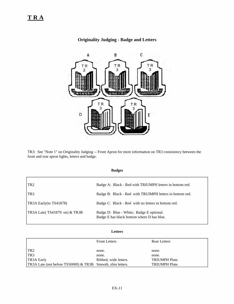
Originality Judging - Badge and Letters
TR3: See "Note 1" on Originality Judging -- Front Apron for more information on TR3 consistency between thefront and rear apron lights, letters and badge.
Badges
TR2 Badge A: Black - Red with TRIUMPH letters in bottom red.
TR3 Badge B: Black - Red with TRUIMPH letters in bottom red.
TR3A Early(to TS41878) Badge C: Black - Red with no letters in bottom red.
TR3A Late( TS41879: on) & TR3B Badge D: Blue - White; Badge E optional.Badge E has black bottom where D has blue.
Letters
Front Letters Rear Letters
TR2 none. none.TR3 none. none.TR3A Early Ribbed, wide letters. TRIUMPH Plate.TR3A Late (not before TS50000) & TR3B Smooth, slim letters. TRIUMPH Plate.

T R A
EX-12
Originality Judging - Hood, Trunk, and Doors
Hood
TR2 Early TR2 Late, TR3, TR3A Early TR3A Late, TR3BTS1:TS6500 (approx) (to TS22530)
- 4 slits in raised portion; no vent. - 2 slits in raised portion; vent. - 2 slits in raised portion;vent.- Rivets on rear edge (to stiffiner). - Rivets on rear edge. - No rivets.- Hood release inside car up to TS4228; - Dzus fasteners on each side of - Dzus fastereners.ater cars have Dzus fasteners. front edge. - Hinges: See Note 2.
Trunk
TR2 and TR3 TR3A and TR3B(and some early TR3A)
- Lock face in center (no handle). - Lock with handle (no escutcheons). - Tear drop escutcheon on either side of lower - Hinges: See Note 2.edge.
Doors
TR2 Long Door TR2 Short Door and TR3 TR3A and TR3B(TS1:TS4002)
- No external handles. - No external handles unless - External handles.GT kit option installed.
- Wood frame door. - Wood frame. -Wood frame thru TR3A TS60000;steel later.
Note: Wood frame doors used on TR2 thru earlier TR3As (approximately TS60000) can be identified by squaredoff bottom corners of the boxed inner door. Later steel doors have rounded corners. For cars within 100 numbersof the TS60000 break point verify that both doors have the same style.
Note 2: TR3A -- Early and Late Variations
On later TR3As and TR3Bs the hinges sit on a raised outline on the hood, front scuttle, the trunk , and the rearscuttle. Hinges on the earlier cars sat on flat surfaces with no stamped, raised, areas underneath. The breakpoint isaround TR3A TS60000. For cars within 100 commision numbers of the break point allow either configuration, butinsure that the hood, trunk and both scuttles are stamped the same.

T R A
EX-13
Originality Judging - Rear Apron
TR3: See "Note 1" on Originality Judging - Front Apron for information on TR3 consistency between front andrear apron lights, letters, and badge. Recall that cars near the break point (TS15601) may have early or lateconfigurations but they must be consistently early or late from front to rear.
Early (TR2 and Early TR3)
Tail Lights Function: Tail lights and turn signal.Appearance: Early TR2 (TS1:TS1301) are squared off, red. Late TR2 and early TR3 are more rounded.
License Plate Illumination Funtion: License plate light and combination stop lamp.Appearance: Red or amber.
Reflectors Function: Light reflection; TR2 optional.Appearance: Round, red, bicycle-like reflector, hung with strap from Tail Light. Escutheons (Spare tire door) Are round (not tear-drop).
Late (Late TR3, TR3A, and TR3B)
Tail Lights Function: Tail lights and stop lamps. Appearance: Tear drop, red.
License Plate Illumination Funtion: License plate light only.Appearance: Chromed cover, clear lens.
Turn Signal Lights Appearance: Red or amber, round.Letters TRIUMPH plate on TR3A and TR3B; not present on late TR3.Escutheons (Spare tire door) Are round (not tear-drop).

T R A
EX-14
Miscellaneous Exterior Evaluations
Scope. Miscellaneous items include several mounted components. These are to be judged in terms of quality andoriginality.
Scoring. Points are earned in increments of whole points. For example, a 2 point allocation can be scored as 0, 1,or 2 points. Negative scores are not permitted. Refer to the Exterior Scoring sheet to determine point allocationsper item.
* Originality: No points should be awarded for component originality deviations. Multi-partcomponents (eg., fasteners) should be deducted proportionally if only portions deviate.
* Quality of Restoration: Award points for quality using the following rules of thumb:
Maximum points Excellent, " Like New" condition"Partial Good conditionNo points Poor condition: damaged
Badge and Letters- Badge and Letters are scored together. Configuration and style varies. See Originality Judging
- Badge and Letters.- Look for chrome pitting and wax not removed from edges.
Lights - Refer to Originality Judging - Front Apron and Originality Judging - Rear Apron.- Surfaces (rubber, glass, chrome, lens) should be clean and in good condition.
Grille - Refer to Originality Judging - Front Apron.- Should be clean, polished, and fit without bowing.
Bumpers- Front bumper, over-riders and support springs (support brackets). TR2 & TR3 bumpers and
over-riders are different from TR3A & TR3B. They are not interchangable. - Rear bumperettesare the same for all models.
- Support springs should be painted low gloss black. The back sides of bumpers should be flatsilver.
- Plastic molding should be present and in good repair between over-riders and front bumper.Windshield
- Includes: Windshield glass, frame and wipers. See fasteners below.- Frame to body securing for TR2, TR3, and early TR3A is with slotted dzus fasteners; a chromed
stanchion guide plate is positioned between frame and body at point of attachment. TR3A andTR3B frames are secured to body with chrome bolts (no chromed plate gasket).
- Wipers arms should be original type, not modern replacements.- Inspect frame, chrome, glass, and rubber seals for wear and general condition.
Hinges - TR2 hinges are painted the same color as body. TR3, TR3A, and TR3B hinges are chromed.- Gasket should be present between hinge and body.
Fender Beading/Welt - Welt (TR2) should be body color.- Stainless Steel fender beading (TR3+) should be unpainted in good condition. - Welt/beading should be flush with rear of front fender. Should be at least flush with front of
both fenders. (May extend past front of rear or front fender). Fasteners
- TR2: baby tenex is used for windshield top, doors, and rear scuttle.- TR3, TR3A, TR3B: tenex fasteners are used on the windshield top; lift-the-dot fasteners are
used on door and rear scuttle. Original lift-the-dot male fasteners are tapered, not straight.

Underhood
Table of Contents.
UNDERHOOD.............................................................................................................................................................1
TABLE OF CONTENTS..................................................................................................................................................1
UNDERHOOD - INTRODUCTION .........................................................................................................................2
ACKNOWLEDGEMENTS. ..............................................................................................................................................2REVISION HISTORY.....................................................................................................................................................2REFERENCES...............................................................................................................................................................2
UNDERHOOD JUDGING .........................................................................................................................................3
UNDERHOOD SCORESHEET .........................................................................................................................................4
UNDERHOOD ORIGINALITY GUIDE..................................................................................................................6
UNDERHOOD - IDENTIFICATION PLATES.....................................................................................................................6UNDERHOOD - INNER FENDERS..................................................................................................................................7UNDERHOOD - BATTERY ............................................................................................................................................8UNDERHOOD - ELECTRICS..........................................................................................................................................9UNDERHOOD - HYDRAULICS ....................................................................................................................................12UNDERHOOD - ENGINE.............................................................................................................................................14UNDERHOOD - FUEL SYSTEM ...................................................................................................................................19UNDERHOOD - CONTROLS ........................................................................................................................................22UNDERHOOD - COOLING SYSTEM.............................................................................................................................24

T R A
UH-2
Underhood - Introduction
This guide is intended to serve as reference for judges in TRA concours events and for TRA members doingrestorations. The material presented is the result several years of assembling information from factory referencematerial, TRA members expertise, TRA judging school reviews and comments, and other Triumph history andreference material.
Acknowledgements.
1990 TRA Underhood Judging School (Video) -- Conducted by Tom Householder (COCTRA).
Authors and principal contributors: John Gabel, Joe Richards, Tom Householder (COCTRA).
Other reviewers and contributors: Jim Conley (Mason Dixon/TRA), John Warfield (Mason Dixon/TRA).
Revision History.
June 1990 - Initial version.June 1991 - Minor edits and corrections. Underhood sections added: Identification Plates, Electrics,
Hydraulics.May 1992 - Added sections on Engine, Fuel System, Controls, Cooling system. Minor corrections and
edits to other sections.February 1993 - Minor extensions, edits, and corrections.May 2000 – Minor edits, extension. Replacement of “Underhood Scoresheet and Originality Deduction
Guide” with redesigned scoresheet which includes deduction guidelines.
References.
The following are referenced where appropriate within "Underhood". The abbreviations enclosed in parens areused to identify the associated reference.
(SPCEd1) Triumph Sports Car Spare Parts Catalogue, Edition 1. Part No. 501653/USA. (SPCEd2) Triumph Sports Car Spare Parts Catalogue, Edition 2. Part No. 501653/USA.(SPCEd3) Triumph Sports Car Spare Parts Catalogue, Edition 3. Part No. 501653/USA. (SPCEd4) Triumph Sports Car Spare Parts Catalogue, Edition 4. Part No. 501653/USA. (HWC) Stanpart Hardware Catalogue for use with Standard Triumph Vehicles. Publication part
number 514264.(TSOAHb) Triumph Sports Owners Association Handbook, 2nd Edition.(Robson) The Triumph TRs, A Collector's Guide, Graham Robson, 1977, Motor Racing Publications
LTD.

T R A
UH-3
Underhood Judging
Scope -- Underhood inspection consists of evaluating the maintenance quality of the components and originality.Components earn points for quality of restoration then deductions are made for originality deviations.
Scoring -- Quality of restoration points are allocated to Underhood component categories (Battery, Hydraulics,Controls, etc.). The lowest possible score per category is zero; negative scores are not permitted.
General Evaluation and Scoring Guideline -- The inspection should be done from the point of view that the carshave been driven and each and every component will not be like showroom quality. For example, a used manifoldwill not retain it's original color. Better than showroom quality should not earn more or less than a component in"like-new" condition. For example, a highly buffed carb housing should not earn more points than a carb housingpresented normally. Over-restoration: Extreme over-restoration may qualify for originality deductions. Forexample, a surface that is not shipped chromed, should not be chromed. One exception is manifolds; they may bepainted with high temp, neutral colors.
Caution: You may not remove or disassemble components to inspect.Avoid touching the car or components.
Quality of Restoration Inspection --
Presentation...... Flaws.............................................................................................Installation Incorrect mounting
Improper retaining of wiring of fluid lines.Appearance Surfaces worn, badly scratched.
Rusted surfaces., pitted chrome. Cleanliness Grease, Dirt GrimeAttention to Problem Repairs not performed: dents, dings, or rust have not been repaired.
Cracked or broken cap or boot.Hydraulic or oil leaks.Frayed or damaged wiring.
Points Earned.... Evaluation......................................................................................Maximum Points Components in excellent condition, free of sings of repair, and installed
correctly.Partial Components in good condition with some minor flaws: visible signs of
repair, lack of repair, or lack of attention to detail.No Points Numerous minor flaws: neglected repairs, consistently poor workmanship,
lack of attention.
Originality Deductions -- Originality deductions cannot exceed the points earned for Quality of Restoration in agiven category. A deduction guide is incorporated into the scoresheet. Generally, the guide outlines deductions percategory as:
Incorrect Component The (or a) primary component is not original to the model.
Major Assembly Deviation A portion of the assembly is not original. A wrong variation of thecomponent is installed or an improper substitute is installed.
Minor Deviations A minor portion of the assembly is incorrect or missing.

TRA
Category Originality Deductions Quality Quality OriginalityPoints Earned Deductions
Identification Plates 5 pts 3 pts 1 pts 5
Commission Missing or incorrect Eng# less Comm#Plate fasteners or location 2
Chassis Missing or incorrect Chassis pl painted 2EB Missing or incorrect EB paint 1
Inner Panels 5 pts 3 pts 1 pts 10Firewall Incorrect panel Panel not body paint Mount HW finish 3Inner Fenders Incorrect panel Hood support Mounting HW 3Hood underside Hood latch Box to body seams 3Washer bottle Bottle not period 1
Battery 5 pts 3 pts 1 pts 5Battery Battery not stnd 12v Battery cables Finish 1Cables Starter cable Not lead caps 2Securing Assemb Securing assembly Securing nuts 2
Box to body seams Boot on + lead
Electrics 5 pts 3 pts 1 pts 20Wiring Harness Incorrect component Harness insulat. type Finish 4Wipers Wire striping 2Starter Starter cable Routing/dressing 2Solenoid Mounting HW 1Voltage regulator Spade vs screw conn Mounting position 2Fuse box Fuses Fuse spares 2Flasher unit 1Coil Coil decal 2
Generator
Generator, coil, horn, or wiper
terminals 2Horns 2
Hydraulics 5 pts 3 pts 1 pts 10Clutch/brake Master cylinder assembly Incorrect assembly Incorrect: Incorrect: 5Hydr lines Hyd lines Resv. decal 2
C/B line adapter Mount hardwareRestrictor valve
Slave cylinder Slave support rod 3Slave spring
Slave mountingPedal stops
Underhood ScoresheetEntry:
Commission #:
Owner:
Model/year:
UH-4/5

TRA
Category Originality Deductions Quality Quality OriginalityPoints Earned Deductions
Engine 10 pts 3 pts 1 pts 25Incorrect Incorrect: Incorrect:
Block component Removal HW Finish 5Drain cock Eng Serial # expose
Ground strap 7Head Head bolts Decals
Rocker cover 5Oil filler cap Mount hardware 3
Oil filter Oil dip stick, breatherDistributor Distributor clamp plate Distributor terminal 3
Distributor capSpark wires VA line routing
Vacuum advance Hoses Clamps 2
Fuel System 5 pts 3 pts 1 pts 10Carbs Incorrect component Incorrect: Incorrect: 2Float bowls Linkage Finish 2Air filters Fuel lines Routing 2Manifolds Hoses Decals 2Fuel pump Mount hardware 2
Clamps
Controls 5 pts 3 pts 1 pts 5Steering Unit Incorrect component Incorrect: Incorrect 2Temperature Sending Unit Steering brackets Finish 2Cables Tach or Speedo cable Cable routing 1
Rubber
Cooling System 5 pts 3 pts 1 pts 10Radiator Incorrect component Incorrect: Incorrect paint 3Fan Hoses Wrong or missing 2Water pump Heater return clamps 2
Thermostat Water pump pulleyMissing water pump grease fitting 1
Heater valve Routing 2Total Quality pts earned and subtract originality deductions Total possible 100
UH TotalJudges Annotation Key: Circled item`- originality deduction Underlined item - quality deduction
UH-4/5

T R A
UH-6
Underhood Originality Guide
The following sections provide originality reference material for the major areas that are contained within theengine compartment.
As in other sections, judges and restorers alike should recognize that even the most well documented changes aresubject to a significant margin of error due to the mass production processes used in TR assembly. Referenceinformation should not be considered the absolute "gospel". Unless otherwise extended for specific components, amargin of error of 200 engine or commission numbers should be used throughout "Underhood."
Each section begins with a chronological summary of changes to that area and is followed by detail on individualcomponents.
Note that factory material and other references use engine and commission numbers to documentchanges. In this document any a TS or other stem is a chassis commission number unless it endsin an "E". Commission numbers ending in "E" are engine numbers.
Underhood - Identification Plates
______________________________________________________________________________________ TR2, TR3, TR3A, TR3B All models
______________________________________________________________________________________
Commission Plate (Vehicle Identification Plate). The Commission Plate, a stamped metal plate with blackbackground, is located on the right hand side of the firewall. Mounting is done with aluminum rivets. Four stylesof plates were used:
TR2, Early TR3 The "20TR2" plate is roughly 4 inches square with corners cut off. The "20TR2" isfound at the top of the plate.
Late TR3 The "20TR2" changed to "20TR3" but the shape is the same.
Later TR3 Some "20TR3" plates later are found with the bottom half cut off. These may be foundwith holes drilled for the larger version.
TR3A/B Later "20TR3" plates are rectangular, roughly 2 inches high by 4 wide.
Note that it is illegal to tamper with the Commission Plate. Therefore no deductions can be made for condition.
Chassis Plate. This is a brass plate mounted on the firewall above and left center of the battery. Mounting is donewith pan-headed, slotted, sheet-metal screws.
EB Plate. This plate is mounted above the Chassis Plate. Mounting is done with pan-headed, slotted, sheet-metalscrews. The plate is painted body color. Numbers stamped on plate begin with "EB". TR3Bs do not have the EBplates.

T R A
UH-7
Engine Block Number. The engine number is stamped on a flat surface on the left-hand-side of the engine. This isjust below the #3 spark plug, at the rear of the coil mounting bracket. Since more engines were made for useoutside the TR line, the engine number in a car should be greater than the commission number of the car. See"Underhood - Engine" for judging guideline.
Underhood - Inner Fenders
______________________________________________________________________________________ TR2, TR3, TR3A, TR3B All models
______________________________________________________________________________________
Hood Securing Hardware. Two major variations are found. The early TR2 configuration was used from TS 1 toTS4228 (SPCEd4, plate AJ, pg 86). The early version used a cockpit pull release while the later version used twoDzus fasteners on the bonnet.
• Early Release – Cable with a pair of springs. The cable runs through the right-side firewall and runsalong the top of the inner fender, near the water channel. Two clips secure it to the inner fender alongthe run. The cable then connects to the left-side lock mechanism and a second cable runs to the right-side lock mechanism. Two springs and locating pins are mounted on the bonnet which snap into thelock mechanism on the body.
• Late Release – Dzus release and single spring. The early cable release is replaced by two Dzusfasteners on front of the bonnet. The dual springs previously located where now Dzus fastenersappear are replaced with a single spring in the middle.
• Prop Rod and Safety Catch – This is used throughout although the rod’s orientation is turned toaccommodate a different “safety hook engagement” at the body.
It is believed that the release mechanism and prop rod, including the early version’s cable, was installed prior topainting of the body shell so that the components were painted body color. Natural or body color is accepted on therelease components not part of the body or bonnet (e.g., cable, springs, spring-thimble cup).
Washer Bottle. The washer bottle was a dealer option. It should be judged from a quality standpoint. Deductionsfor originality should be made only if the bottle is obviously not of the period. The typical washer bottle is glass (onthe early cars) or soft plastic bottle with "Trafalger" embossed on the side. Routing of the tube is normally behindthe oil pressure line, along the front of the battery box, and through the bottom hole in the firewall.

T R A
UH-8
Underhood - Battery
______________________________________________________________________________________ Battery Variations Summary
TR2 TS3268 Drain tube added.TR3 TS18913 Battery cable (lead) changed - no details.TR3A TS60001 Battery cable (lead) changed - no details.
______________________________________________________________________________________
Battery. The battery is a standard 12 volt battery. The originals were black "tar-top" batteries. Batteries installedshould be standard size. Post location should allow for normal routing of cables.
Battery Securing. Components:* Securing Bracket - Plate with center cut out that is welded to body. Early models were light sheet metal; latermodels were stamped, heavy gauge steel. Is part of the body and painted body color.
* Angle Bracket - angled steel flattened where holes are drilled for securing rods. Should be painted black.
* Securing Rods - Hooked on end for slip over retaining bracket on body. Should be unpainted or black.
* Wing nuts and felt washers - Tie down securing rods to angle bracket. Early models had brass wing nuts;later models equipped with steel; no details on brass to steel changes. Nyloc nuts (Simmonds FullNyloc, 7/16 Unified Fine Thread, ref: HWC pg 13) are specified ( SPCEd4, pg 140) . Nuts can bepainted black or left unpainted.
Battery Box. The box is part of the body shell. Where the box is welded to body shell, the sheet metal seamsabove and in front of the battery should be glazed but clearly visible.
Battery Box Drain. The drain added in late TR2s is not visible with the battery in place. The modificationconsisted of rubber plates, a drain tube through the battery box floor and tube mounting clip. Battery Box Liner. Anoptional plastic liner is allowed. Common was Amco liner.
Battery Cables (Battery Leads or Engine Leads). Three variations are listed in the parts manual corresponding tothree changes to the wiring harness; no further details. Original cables are characterized by lead caps that attach tothe battery posts. Through the center of the lead caps, a sheet metal screw is turned into the top of the posts. Thelead cap connectors provide marginal contact with the posts and some dealers reportedly replaced these withconventional clamp connectors.
* Earth Lead (ground)-- This is a round, woven cable. No sheathing.
* Positive (Solenoid) Lead -- This cable is sheathed; a rubber boot appears on the solenoid connection.

T R A
UH-9
Underhood - Electrics
______________________________________________________________________________________ Wiring Harnesss Variations Summary
TR2 TS1TR3 TS12569 Wiper motor change.
TS13046 Hydraulics change/stop lamp change.(TS15601) Turn/stop light configuration change. (Part number change not
referenced)TS18913 Battery cable (lead) changed - no details.
TR3A TS60001 Change to vinyl wrap and spade connectors; battery cable (lead) change - no details.
EB64561 Engineering body change - no details_____________________________________________________________________________________
Other Components Variations Summary
Windscreen WipersTR2 TS954 Optional 2-speed wiper motor change.TR3 TS12568 Standard 1-speed and 2-speed wiper change to LHS.
Voltage Regulator, Fuse Box, Flasher UnitTR3 TS9894.... Flasher unit change.
Starter Motor, SolenoidEarly (TR2,TR3,early TR3A) TS1:TS50000 Button nose starter.Late (late TR3A, TR3B) TS50001... Long nose ("quiet") starter.
GeneratorEarly (TR2,early TR3) TS1:TS9842 No details. Believe is banded style generator.Late (Late TR3, TR3A,TR3B) TS9843... No details.
Coil (Ignition) TS1:TS11812 Lucas "big" coil. TS11813... Standard "CB(SW)" coil. TS38177... Distributor lead changes.
Horns No changes in export models______________________________________________________________________________________
Wiring Harness. The main wiring harness was wrapped with black cloth. On early models connections tocomponents were with screws and wires were wrapped with lacquered cloth insulation. Later harness was insulatedwith vinyl and connections are made with spade and bullet connectors. Variations above correspond to changes incomponents or component locations. Note that the front and rear turn and stop lamp changes at TS15601 thatobviously required changes in wiring are not reflected in a corresponding part number change in the parts manual.
Replacement Harnesses - Yellow/Orange striping. Replacement cloth harnesses offered may have striping on themain harness sheathing. There is no commonly accepted evidence that this was ever done originally.
Wiper Motor. The common motor assembly found is the single speed version. An optional 2-speed motor wasoffered however.
Components. Visible components include:

T R A
UH-10
* Wiper Motor/Motor Cover - cover is bakelite, painted blue, silver, or matte black. Electric connectorschange to spade at TS60001 (part number does not change).
* Gearbox - metal casing bolted to motor, unpainted.* Crosshead and rack - the cable and shaft connecting gearbox and wheelbox (in firewall). Unpainted.
Change from RHS to LHS. At TS12568, the wiper assembly was moved from the RHS of the compartment to theLHS. All components changed.
Optional 2-Speed Wiper. Compared to the single-speed wiper, the 2-speed assembly has the same wipers, wiperarms, wheel box, and outer motor to wheelbox casing; differences were in motor and gearbox. At TS955, adifferent motor-to-wheel-box casing and casing between wheel boxes were fitted (no further details).
Voltage Regulator (Control Box), Fuse Box, Flasher Unit. The Voltage Regulator and Fuse Box is the samebasic unit on all models.
Spade connector change TS6001. Components were fitted with spade connectors with the change to the wiringharness.
Fuse Box. The box should contain in place 1x35 amp fuse and 1x50 amp fuse. A spare for each should also bepresent in spare holders. A cover is fitted to later models (at TS60001). The older fuse boxes will not accept thecover.
Flasher Unit. Although the parts manual only lists one change, three flasher unit variants are known:
* Early TR2 - cylinder mounted horizontally; screw tab at end to left.* Late TR2/TR3/Early TR3A - Screw through center; connectors at top, mounted vertically.* Late TR3A/TR3B - Screw tab at top, mounted vertically, spade connectors.
Either of the first two is acceptable for TR2s. TR3s should be fitted with the second. TR3As may have either latervariants. TR3Bs should have the last version.
Mounting Configuration Variations. Variations include:
* Early TR2 configuration - Voltage regulator mounted with connections pointed down. Flasher Unitmounts with screw on left and body extends horizontally.
* Late configuration - Service bulletin (Sports 2/M) in February 1954 announced change because ofproblems due to heat from the engine affected reliability of flasher unit capacitor. Regulator mountingis changed to connectors pointing to the left.
The early configuration is commonly found well into 1955 titled cars. All cars TS60001 and after should have laterconfiguration. TR2s after TS138 may have either configuration.
Starter Motor, Solenoid. The same solenoid is fitted to all models. The solenoid fitted to TR4s is interchangeablefunctionally. The TR2/3/3A/3B solenoid should be fitted; it is cylindrical with rubber button for underhood startup.The starter change at TS50001 is the only change. The starter motor casing is painted matte black. Solenoid isunpainted.
Generator. Two housing variations were supplied by Lucas. One is a simple cylinder; the other housing isstepped roughly in the middle with the step up the thickness of the housing. Housing is painted matte black; endcovers should be unpainted. No decals. In addition early generators had a band on the brush end of the housingthat could be removed to allow access to the brushes; these were probably used up to TS9843. The stepped housingwas probably introduced at TR60001. TR3As and TR3Bs should not have the banded style generators or "fanless"generators; otherwise any of the variations are acceptable on all models.

T R A
UH-11
Electrical connections. The generator electrical connections change to spade connections at TS60001. On earlymodels, the armature (large) lead should be covered with a black rubber insulator; later models (from TS60001)with a clear vinyl boot (discolors to orange shade with age). The field (small) lead connection on the spade makes aright angle; should not be straight; the lug connection should come straight out.
Horns. Two horns are fitted: one high tone and one low tone. Horns are stamped with "H" and "L" on top surface.The same versions were fitted to all export models. Domestic market horns did have variations. Horn bodies arepainted gloss black. Mounting is with hex bolts through 2 heavy flat washers.
Coil. Early cars were equipped with a bigger, taller, Lucas coil. The later standard coil was used on all latermodels. Connectors change to spade at TS60001. Cap is black with silver body. Lucas decal may be fitted; thedecal was fitted originally but is not required. A black screw-on cap should be fitted (not push-on).
Distributor Lead Change. At TS38177, the lead from the distributor changes. No details.
Competition Coil. An optional high performance coil is available and in common use. This is distinguished by ared cap.

T R A
UH-12
Underhood - Hydraulics
______________________________________________________________________________________ TR2, Early TR3 TS1:TS13045 Lockheed system______________________________________________________________________________________
The TR2 and early TR3s are fitted with Lockheed drum brakes on all four wheels. The clutch/brake master cylinderassembly is characterized by cylinders and a common reservoir contained in an integral unit. Service to one systemrequired service to both. Inspection of the C/B master cylinder assembly:
* Cover plate and unit should not be painted* Filler cap should be black.* Brake and clutch lines should not be painted with color (should be galvanized or painted galvanized)* Boots fitted should be accordion type. * Slave cylinder different from Girling sytems; is short, fat, and rounded.
______________________________________________________________________________________Late TR3,Early TR3A TS13046:TS34310 Girling system introduction
TS20310... Restrictor value added, brake line change.TS22530... LH/RH drive reversal plates dropped. TS33944... Slave spring change - no details.TS34311... Brake cyl to 5xway line change - no details.
______________________________________________________________________________________
The introduction of the Girling system with front disk brakes resulted in the complete replacement of theclutch/brake hydraulics assembly. Distinguishing characteristics:
* Fluid reservoir unit is separate, independent from cylinders; painted black; "Clutch" and "Brake"decals on sides of reservoirs. A red and blue Girling decal may be on clutch side of reservoir. TheGirling decals may be fitted although they are believed to have been discontinued in 1957.
* C/B cylinder output is straight up to line connector.* C/B cylinder line adapter is required -- no details.* C/B push rod connection to pedal assembly made with threaded clevis pin.* Pedal adjustment bolts are mounted in the front plate of assembly mounting bracket.* 5-way connector added to frame (passenger side).* Clutch slave cylinder is longer and thinner than Lockheed cylinder; mounted with bleed port at top; two styles of support rods can be fitted: one has L turn, the other has a simple angle bend.
Restrictor Valve Modification. The valve (tower) was added to the brakes' 5-way connector to more evenlydistribute pressure to the four wheels. This modification resulted in a brake line part number change to account forthe change to input to the top of the tower.
Reversal System Change. The body and assembly mounting changed. The early version allowed switching to LHdrive to RH drive via screw mounted plate. In later models the box was welded into the body.
______________________________________________________________________________________Late TR3A, TR3B TS34311... Later Girling system
TS60001... Stop lamp switch to spade connect______________________________________________________________________________________
The later girling system installed had minor revisions to the master cylinders. Distinguishing characteristicsinclude:

T R A
UH-13
* C/B cylinder slanted outputs changed to slant forward instead of straight up.* C/B cylinder line adapters removed.* Pedal adjustment bolts removed with no pedal stop adjust (see note below).
Note: Pedal adjustments may have been fitted to cars for some time after TS34311. The part manual does notindicate that this feature was ever removed. Fitting of adjusters on later cars is considered acceptable up throughTS60000.
The stop lamp switch changed from screw-on to spade connectors with the change in wiring harness at TS60001.
Notes on part manual references at TS34311:
* Cylinders change - details above.* Brake Line from cylinder output to 5-way connector changes - no details.* C/B adapters are removed - no details.* C/B cylinder supply lines (to reservoirs) and clutch to slave line do not change. * Pedal assembly does not show change except at TS13046.

T R A
UH-14
Underhood - Engine
______________________________________________________________________________________ Engine Variations Summary
Model Commission# Engine# DescriptionTR2 TS1 TS3E
TS972E Breather pipe/cylinder block changeTS8997E "TR3 Engine" -- Cam bearing locating screws added;
H6 carb & manifold change TR3 TS8637 TS9350E LeMans Head introduced, requires manifold change
TS9952E Oil Filter head flange thickenedTS12650E Oil Filter head change -- Full Flow filter
TS12606E:TS13052E High-port Head introduction TS17372E Oil Filler Cap change -- no details TS18230E Rocker Cover change -- no details TS18902E Oil Plug change
TR3A TS22014TR3B TSF1 TSF1E
TCF1 TCF1E 2138cc TR4 engine used ______________________________________________________________________________________
Engine Number and Commission Number. The Commission Plate (see Underhood - Identification Plates), astamped metal plate with black background, is located on the right hand side of the firewall. The engine number isstamped on a flat surface on the left-hand-side of the engine. This is just below the #3 spark plug, at the rear of thecoil mounting bracket. Engine numbers are similar to Commission numbers but engine numbers have an "E" suffix.Take fair warning that parts manuals frequently leave off the "E" leaving the reader to his better judgement as towhich is really being referenced. The 3rd Edition of the "Triumph Spare Parts Catalogue" is a good example; itintermixes engine and commission numbers in the engine section (the 4th Edition, however, makes clear use of "E"suffices). Generally, if you are talking engine parts, the number listed is likely an engine number - "E" or no "E".
Engine Production. Some TR engines were used outside the TR line (Doretti and Morgan); therefore, the enginenumber in a TR should be equal to or greater than the commission number of the car. Beyond that, sufficient carbuild records are not available for precise identification of engine numbers at model break points. During TR2production, information available indicates that roughly 500 additional engines were built. After TR2 production,records are lacking and information so inconsistent it is difficult to provide estimates.
For judging purposes, use the following guideline:
* Incorrect Component -- if the engine number indicates that the engine configuration installed was notinstalled on the car, a major deduction is taken. For example, if a High Port head is found on a TR2, thiswould be an incorrect component and a major deduction will be made.
* Minor Deviation -- if the engine installed is of the type installed for the commission number but thenumber indicates the engine is not original to the car, a minor deduction will be made.
TR2-TR3 Break Point Confusion. Several changes occurred near the end of TR2 production and the beginning ofthe TR3 production. The spare parts catalogs (ref SPCEd4) do not provide an explanation. The best explanationwe found is in the TSOA Handbook; related information is found in Robson.
Low Port Head and H6 Carbs. The first questions of interest are where the Low Port Head usage ended and whereH6 carbs were introduced. According to TSOA (ref: TSOAHb, pg 114), Low Port head usage ended at engineTS9349E, the last TR2. However, a manifold change and the H6 carb change occurred at TS8997E (ref SPCEd4,

T R A
UH-15
pg 17). This seems to conflict with the general assumption that H6 carbs were introduced with TR3s. Theconflicting information starts to make sense when TSOA further explains that TR2s from TS8971E (and we assumethat this is the same change listed at TS8997 in SPCEd4) were fitted with "TR3 engines" but Low Port heads. Thelatter explains why a different manifold was needed between TS8997E and TS9349E where H6 carbs were installedwith Low Port Heads for a short time.
High Port Head Introduction. TSOA (ref TSAOHb, pg 114) also provides insight into conflicting engine numbersused in various sources to describe High Port head introduction. Robson (1) gives a comparable description of thisperiod. According to Robson, within weeks after the introduction of the TR3, several engine changes were madeincluding the introduction of the LeMans head and the High Port head. Between engine TS12606E and TS13052"there was no logic as to which combination (LeMans or High Port) would be found when the engine was finallyfitted to the car"!
TR2-TR3 Engine Configuration Judging. For judging purposes, use the following originality guidelines:
* TR2 -- Cars through TS7899 should have early engines (pre-TS8997E configuration). Early or lateconfigurations are acceptable on TR2s from TS7900:TS8199. Late TR2s, from TS8200, on should have"TR3 Engine" configurations listed above as introduced from TS8997E through TS9349E.
* TR3 -- TR3s with commission numbers up to TS14000 (which should encompass engine numbers up toapproximately TS13100E) will be assumed original with any combination of component variations listedabove as introduced from TS8997E through TS13052E. Later cars should have the High Portconfiguration.
Combustion Head. All heads described below should be painted black. Bolt heads and nuts may be paintedblack, left unpainted or blued.
Low Port Head. The low port was used through TR2 production; the last engine that used it was TS9349E (ref:TSOAHb, pg 114). This head is distinguished by a flat profile.
LeMans Head. Introduction is listed at TS9350E (believed to be in the first TR3, TS8637). It is similar inappearance to the Low Port. While the Low Port provides a short emboss (raised outline) for head bolts, the LeMans head embosses are high -- about 1/2 inch. Functionally, the LeMans provides improved air flow passagedesign resulting in improved horsepower.
High Port Head. Introduction is listed at TS13052E. Better air flow is provided. Unlike the flat-top predecessors,the HIgh Port profile from the carb side has four humps to accept manifold intakes.
Late High Port Head - TR3B. TR3Bs with TCF numbers might be equipped (no reference available) with TR4versions of the High Port. These are distinguished by a flat crown on the front-most "hump" on the head. The flatarea may have a serial number.
Head Bolts and Nuts. Head bolts changed at TS13052E; they had to be made longer for the High Port head. Headbolt nuts were changed at TS8937E (ref: Service Bulletin December 1955); this change was due to "failure" of theearlier nuts; they "changed the material specification of the nuts concerned". The new variety was reported to bedistinguished "by a series of small circles stamped on one or more flats, or alternatively by an annular groovemachined on the top face of the nut". The latter is included for fun only (after cleaning, brushing, and finding somegood light, we did find some circle stampings) -- will not be used for originality judging.
Cylinder Block. The cylinder block did not change significantly until the TR4 engine was introduced. Minorchanges were made. All blocks are painted black.
T R A
UH-16
Breather Pipe Change. According to service bulletins (see Breather Pipe), at TS972E a casting change was made tothe block in conjunction with a change to the breather pipe. The change cannot be detected externally.
Cam Bearing Locating Screws. Three locating screws (part no. 110462, ref: SPCEd4, pg 7) were added late in TR2production at TS8997E (block part no. change from 301138 to 301487, ref Service Bulletin Vanguard/9/B,September 1955) to the block for locating screws; these retain the location of the cam bearings. Blocks producedfrom this point are embossed for the screws. The screws are located between the three oil gallery plugs that layalong the run of the cam shaft. Note that Cam Bearing Locating Screws and corresponding cam bearings may beretrofitted to early engines per instructions in the above-mentioned service bulletin.
TR Paint Markings on Side of Block. All TRs (we believe) were shipped with hand-painted numbers and letters onthe starter side of the engine, generally toward the rear. The most common marking is "TR" above a "2" or "3";early pictures are available of an engine with a "2" laying on its back. Markings are red-orange paint. Markings arenot required but if present should conform to one of the above-mentioned styles.
Rocker Cover and Oil Filler Cap. Except for late TR3Bs, rockers have the oil filler at the front. The late versionhas the filler in the rear (like TR4s). The Oil Filler Caps are push-on type and provide "open-circuit" breathing tothe engine with the integral mess filter. Valve rocker cover variations include:
* TS1 Early cover -- painted black.* Late TR2 Changed to chrome -- apparently no part no. change.* TS18230E (ref. SPCEd4) no details* TCF1 Late version with rear filler.
In addition, early rocker covers had a tab with hole on the rear, distributor side. No details as to when thetab disappeared or its purpose; the tab may have been used in competition setup where the breather is routed upand fastened to the tab.
Black versus Chrome Covers. Sometime prior to TR3 introduction, chrome covers were introduced (quite possiblywith other changes at TS8997E). Black covers had a rectangular decal (black with white lettering) on the distributorside; the decal states valve clearances. TR2s prior to TS8000 should have black covers; after that either chrome orblack are acceptable on TR2s.
Cast Aluminum Valve Covers. According to The Roadster Factory, an aluminum cover was optional equipment.SPCEd4, however, does not specify such as optional high speed equipment or as an accessory. Research onaccessories published in a VTR newsletter (ref: The Vintage Triumph Quarterly Magazine , pg 902) indicates thatwhile these might have been offered from the factory it could not be confirmed; however, such covers weredefinitely dealer options. These covers will be accepted as original equipment.
Securing Hardware. Two nuts with washer and fiber washer secure the rocker cover (ref. HWC):
* Nuts, nyloc -- 5/16 inch United Fine, 1/2 inch flats.* Washer, plain -- 5/16 inch inside, .69 inch outside.* Washer, fiber -- 5/16 inch inside, 1/2 inch outside
Oil Filler Cap. Cap variations include:
* TS1 Early cap* Late TR2 Late cap -- changed to squared style; probably occurs
when cover changes to chrome; apparently no part no. change. * TS17372E (ref. SPCEd4 pg5) no details* TCF1

T R A
UH-17
The early and late caps are similar in appearance. Both are domed with mesh breather filters in the bottom. Theearly cap has a flat top profile; the late cap profile has 3 thumb grips, and a round, domed, profile. Early caps areblack. Late caps are found painted black or hammer-tone (specific color unknown) gray.
Decal. A decal is fitted to the oil filler cap tops. Two basic styles of decals are used. The early decal is divided ina pattern of concentric circles. Later a pie pattern decal was used. The following variations are known:
TR2/3 -- Large concentric circle decal, black with white markings.
TR3A -- Large pie-pattern decal, black with white markings.
TR3A -- Little concentric circle decal, black with white markings fits caps with thumb-holes.
TR3A/3B -- Little pie-pattern decal fits the caps with thumb-holes.
TR3B -- Little pie-pattern decal, Red with white markings (only observed on some TR3Bs withhammertone caps).
Timing Chain Cover. There were no variations. Covers should be painted black and the face covered with sounddeadener, usually a light gray color. The sound deadener should not be painted.
Ground Strap. A round, woven steel, ground strap is attached to the timing chain cover and the front motor mount.The purpose is to ground engine with body by spanning the insulating motor mount.
Oil Filter Assembly. Three versions of the assembly are found (SPCEd4 pg 13):
TS1E Original, with 7/16 flange *TS9952E Flange thickened to 5/8 inchTS12650E Full Flow Filter
* The flange in question is the flange on the head assembly where the head bolts to the cylinder block.
According to Service Bulletin in February 1956, the "flange (filter to cylinder block) of the oil filter, together withthe attachment bolts and stud, have been strengthened. This modification has been made to prevent any possibilityof oil leakage from the joint due to distortion of the flange under loading by the bolts and stud". In addition to the bolts being lengthened, the tensile strength of bolts and stud was also increased.
Full Flow Filter. The filter head was changed to avoid oil flow stoppage should the filter become clogged. Thenewer head includes a bypass and can be easily distinguished from the older versions by a access port on the head.The canister was not changed.
General. All assembly versions have the same general appearance. The head is natural aluminum. The canister ispainted ice blue (specific color unknown) which takes a pale green caste with age. Because of the above-mentionedproblems with the earlier variations of the oil filter assembly, later variations will be accepted on earlier cars;however, an early variation should not be present on a later car.
Oil Drain Plug and Sump. The oil sump shows no changes (ref: SPCEd4, pg. 3) although you may find varyingdegrees of workmanship where the plug insert is welded to the sump that might give the appearance of differentunits. Sumps are painted black. Aluminum Sumps. These were offered as optional high speed equipment. Theyare not painted.
Oil Drain Plug. The plug was changed once at TS18902E. The early plug was a brass cap screw, 5/8s NF, 1/2inchlong, .798 across the flats (ref: HWC pg23). The later plug was a common square steel plumbing plug, 7/16inchacross the flats.

T R A
UH-18
Breather Pipe. Two versions of the breather pipe (dog-legged tube mounted low on the rear of the distributor sideof the engine) were fitted although the two are not readily distinguished without disassembly. The later version wasintroduced at TS972E; it includes an internal baffle to prohibit loss of oil through the breather while running at highspeed. According to Service Bulletin Vanguard/3/B, August 1954, the cylinder block was "modified, withoutchange of Part No. at Eng TS.972E and the Breather Pipe Assembly is affected". The same bulletin offers amodification to older breather pipes to curb oil loss. Breathers are painted black.
Dip Stick. No changes are listed to the oil dip stick. The dip stick is not painted.
Engine Removal Hardware. Removal hardware includes the following components:
* Eye, front lifting assembly (bracket) -- bolted between timing chain cover and front engine plate.
* Rear lifting bracket -- bolted on at rear manifold bolt and at rear head stud. The rear manifold stud islonger than other studs to account for bracket thickness.
Removal hardware is painted black. There are no changes listed in the SPCEd4. However, it is believed that earlycars were not fitted with removal hardware; edition 1 of the Triumph Spare Parts Catalogue does not list removalhardware. For all cars, removal hardware will be considered optional. However, if present both front and rearshould be installed.
Distributor and Vacuum Unit. The same basic distributor unit was employed throughout production. The unitchanged at TS8213 (ref: SPCEd4, pg. 64). The later unit is considered a comparable replacement. A black Lucasdistributor cap should be fitted.
Vacuum Advance Unit. The early style has a large hex snout; sometime during the TR3A production this changedto a conical snout. Both styles have a screw-on connection to the vacuum line from the advance unit to the frontcarb.
Vacuum Advance Line Routing. On early cars with the larger diameter pump-to-carb fuel lines, the vacuum lineruns beneath the fuel line retaining clip at the thermostat. On later cars with the smaller diameter pump-to-carb fuellines, the vacuum advance line is routed through the eye that retains the fuel line at the thermostat. Between thevacuum unit and the thermostat, the line routes behind the bypass hose, although routing in front of the bypass hasbeen observed on cars thought to be original; either will be accepted.
Spark Plug Wires. Several varieties are found. Black wires with insulation boots should be used. Photos in anearly shop manual for TR2s show high-tension wires attached to the spark plugs with clips that are held in place byscrews at the top of the plugs; no rubber boots. Such configurations of the period are acceptable.
Spark Plugs. Normal driving and high speed equipment versions were offered. Any suitable replacement isallowed.
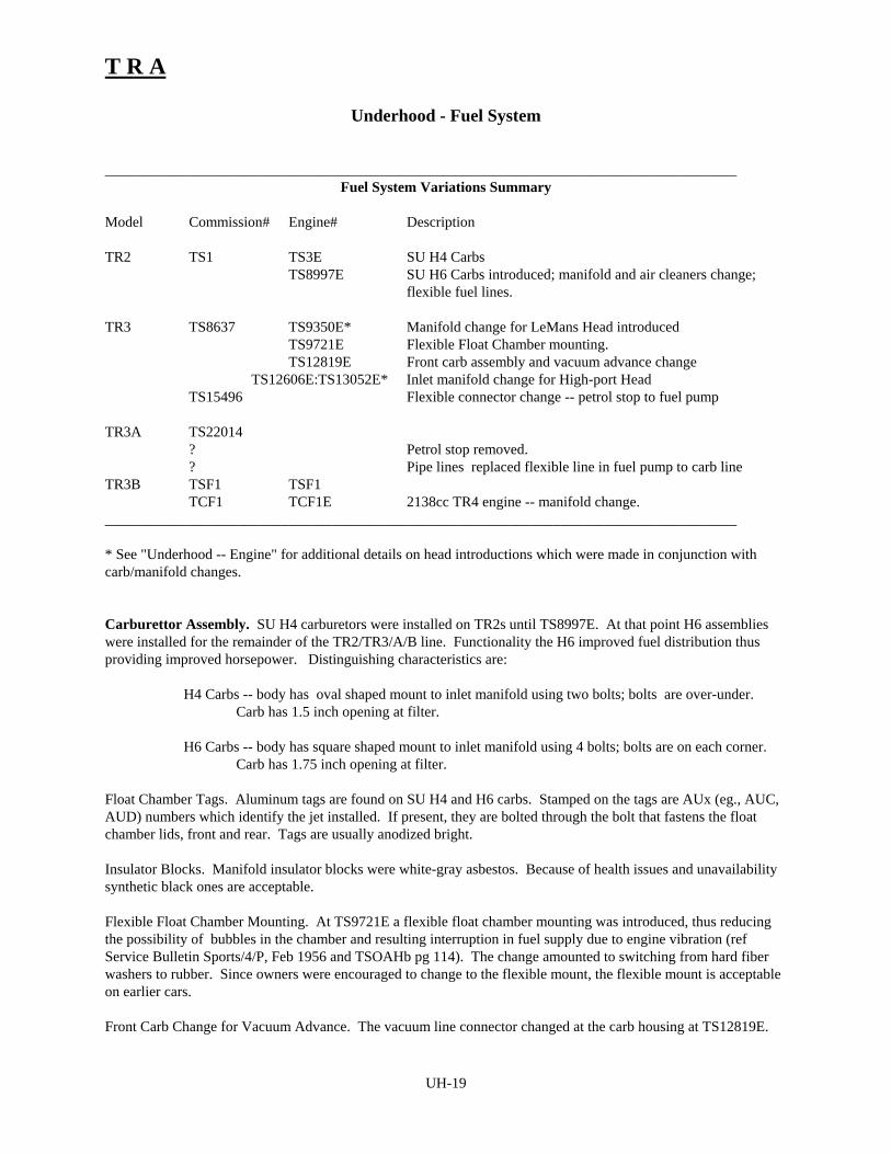
T R A
UH-19
Underhood - Fuel System
______________________________________________________________________________________Fuel System Variations Summary
Model Commission# Engine# Description
TR2 TS1 TS3E SU H4 CarbsTS8997E SU H6 Carbs introduced; manifold and air cleaners change;
flexible fuel lines.
TR3 TS8637 TS9350E* Manifold change for LeMans Head introducedTS9721E Flexible Float Chamber mounting.TS12819E Front carb assembly and vacuum advance change
TS12606E:TS13052E* Inlet manifold change for High-port Head TS15496 Flexible connector change -- petrol stop to fuel pump
TR3A TS22014? Petrol stop removed.? Pipe lines replaced flexible line in fuel pump to carb line
TR3B TSF1 TSF1 TCF1 TCF1E 2138cc TR4 engine -- manifold change.
______________________________________________________________________________________
* See "Underhood -- Engine" for additional details on head introductions which were made in conjunction withcarb/manifold changes.
Carburettor Assembly. SU H4 carburetors were installed on TR2s until TS8997E. At that point H6 assemblieswere installed for the remainder of the TR2/TR3/A/B line. Functionality the H6 improved fuel distribution thusproviding improved horsepower. Distinguishing characteristics are:
H4 Carbs -- body has oval shaped mount to inlet manifold using two bolts; bolts are over-under.Carb has 1.5 inch opening at filter.
H6 Carbs -- body has square shaped mount to inlet manifold using 4 bolts; bolts are on each corner.Carb has 1.75 inch opening at filter.
Float Chamber Tags. Aluminum tags are found on SU H4 and H6 carbs. Stamped on the tags are AUx (eg., AUC,AUD) numbers which identify the jet installed. If present, they are bolted through the bolt that fastens the floatchamber lids, front and rear. Tags are usually anodized bright.
Insulator Blocks. Manifold insulator blocks were white-gray asbestos. Because of health issues and unavailabilitysynthetic black ones are acceptable.
Flexible Float Chamber Mounting. At TS9721E a flexible float chamber mounting was introduced, thus reducingthe possibility of bubbles in the chamber and resulting interruption in fuel supply due to engine vibration (refService Bulletin Sports/4/P, Feb 1956 and TSOAHb pg 114). The change amounted to switching from hard fiberwashers to rubber. Since owners were encouraged to change to the flexible mount, the flexible mount is acceptableon earlier cars.
Front Carb Change for Vacuum Advance. The vacuum line connector changed at the carb housing at TS12819E.

T R A
UH-20
Carb Component Finishes. Carb bodies, float chambers, float chamber lids, piston covers are natural aluminum,sometimes mildly polished. Other finishes include:
Brass (generally with milling marks left in place): throttle shafts spindle return anchor plates, jetadjusting nuts, jet lever, throttle lever, overflow pipe fitting, banjo fittings (when applicable),damper cap lid (nickel plating is known but rare), fuel filters in float chamber lids, andoccasionally float chamber lid bolt, bango bolts.
Black Oxide, Blued, or Natural dark Metal: bellcrank lever assembly, pivot lever assembly, throttlespindle couplings, choke arm, pivot bolt and washer on cam, and speed nuts if fitted.
Clear Cadmium: Short and long throttle links (gold cadmium is bound in later TR4s) front and rear, jetlinks (some jet links on early cars are browned), float chamber hold up bolt and clip washer, fuelline and float chamber banjo bolts, jet control connecting rods, throttle spindle end clips, front jetlever to connecting rod clips, clevis pins.
Other: Sundry screws, bolts, springs, cotter pins, etc. can be plated or left natural as well as the throttlespindle connecting rods. Jet head assemblies have all kinds of finishes, variations of brass, steel,copper, etc.
Air Cleaners. H4 and H6 systems use different filters due to the differences in air openings. The two types are notinterchangeable although identical in outer appearance. Filters are painted black. "AC" decals are placed in thecenter of filters. Decals are round or rectangular (believed changed from round to square in 1957), dark blue, andhave white lettering. Paper element replacement filters which might provide better dust filtering are not acceptablefor concours showing.
Fuel Pump. No changes. Replacements are available that do not include the priming lever. Use of pumpswithout priming levers should not be considered original. Pumps should be unpainted.
Fuel Lines.
Petrol Stop. The petrol stop (shutoff valve), located between the fuel pump and firewall, was removed duringTR3A production (probably in 1958); although a specific break point is not available, cars after TS60000 should nothave a petrol stop. Early in TR3 production the petrol stop connection to the line running to the fuel pump wasaltered; see below. Petrol stops are prone to leakage and may be removed or bypassed for safety reasons; qualitydeductions may be made if removal or bypass is performed with poor workmanship or material not of the period.
Fuel Line from Tank to Pump and Petrol Stop. At commission number TS15497 (not engine number), the flexibleconnector at the petrol stop was changed. The early version connects with a compression tubing fitting (tubingsleeve and tubing nut); the later version has a slip-on rubber hose connection. The line itself changed from flexible,woven steel sheathed, type to rigid steel pipe.
Fuel Line from Pump to Carbs. Three types of lines were used:
* TR2s with H4 Carbs -- Until TS8997E a steel line was used. A strap type retaining clip is used at thethermostat housing. The banjo bolt connections are soldered to the pipes. The banjo bolt at the frontcarb has input and output at 180 degrees. The banjo connections are made to the float chamber lids onthe engine side of the carb. Routing of the line between the float chambers is above the intake manifold,the line is slightly bulged up for improved clearance of the manifold.
* TR2s with H6 Carbs, TR3s, and early TR3As -- Flexible line, a rubber line with woven steel sheathing,was installed just past the thermostat housing on the carb side of the run to the float chambers. A straptype retaining clip is used at the thermostat housing. The banjo connections changed to compression

T R A
UH-21
fittings. The banjo connection at the front carb changed from input-output at 180 degrees to roughly 120degrees; this change along with a change to the float chamber lids allows the routing of the line to godown under the air intake side of the carb housing, avoiding routing over the manifolds.
* Late TR3A,TR3B -- Steel pipe lines with rubber sleeve connectors were introduced sometime during theTR3A production (no details are given in SPCEd4, pg 19 although a later part number is provided). Theretaining clip at the thermostat housing changes to an eye type. At the same time, the banjo boltconnection at the float chamber lids was changed to a rubber sleeve connection. A bent, U-shaped pipeis used between the carbs. Steel pipe lines are smaller in diameter than the earlier lines. Routing betweencarbs is like that of the flexible lines. The original rubber sleeve connectors had a fine pebbly surface;not required. Clamps were not used on the rubber connectors; however, for safety reasons, clamps orwire clamps may be fitted. Cars after TS60000 should have this style of lines. TR3As prior to TS6000may have either this or the flexible line type of lines. Finish of lines is natural.
Fuel System/Safety Issues:
1. Petrol Stop Removal or Bypass. Should removal or bypass be allowed under heading of allowed safetymodification. Yes if modification is conducted in an inconspicuous manner.
2. Inline Fuel Filter. Is this an acceptable improvement? Yes based upon historical rulues. Prefer installationunder car.
3. Clamps on flexible fuel line connections. Should installation be allowed for safety reasons. Yes. 4. Fire Extinguisher. Should installation be allowed under the heading of safety modification. Yes if installed
tastefully in engine compartment, rear of interior, or trunk.5. Weber Carbs. Webers or other high performance carb installation are not considered acceptable for concours.6. Fuel lines late TR2 -- was a flexible line used with H4 carbs and if so what was the routing? If so, routing
along the engine side of the carbs, above the manifold, seems doubtful as the lines would sag too close to themanifold. The parts manual provides no evidence of such a variation. Assume No.

T R A
UH-22
Underhood - Controls
______________________________________________________________________________________Variations Summary
Model Commission# DescriptionTR2 TS1 TR3 TS5777:TS8637 Steady bracket added to lower steering tube.
TS10545 Tac and Speedo cables change.TR3A TS22014
TS27000:TS40000 Split steering and Support Brackets added/changed.TR3B TSF1
TCF1 2138cc TR4 engine ______________________________________________________________________________________
Steering. The same basic unit was installed throughout production. The main change was during TR3Aproduction when the steering tube and shaft were split into two parts.
Rigid Steering Unit. Early cars were fitted with a "rigid" steering column; the tube and shaft are one piececomponents that span the length from steering wheel to the steering box. The tube and securing hardware arepainted glossy black.
Split Steering Unit. Later cars were fitted with a split unit; the tube and shaft are split into lower and upper halfcomponents and the shaft is clamped together. The change was apparently due to production changes, the split unitproviding an easier assembly process (fitting the unit to the chassis and through the firewall). The change point isnot documented in the parts catalog (ref: SPCEd4, pg. 41). Although not documented, there is general agreementthat the change occurred in 1958. The exposed shafts and connector should be natural, unpainted steel.
Rigid vs Split Steering. Use the following judging guideline:
TS1:TS27000 -- should have rigid steering unit.TS27000:TS42000 -- may have rigid or split steering. TS42001 on -- should have split steering.
The range of TS27000:TS40000 roughly covers the production of TR3A during 1958.
Steady Bracket -- Lower Steering Column. Except for early TR2s, cars were fitted with a supporting hardwarethat clamps to the steering tube and is anchored to the frame near the front wheel spring.
TS1:TS5776 -- Early TR2s had no lower steady bracket.
Early, Rigid Steering Steady Bracket -- added at TS5777 or TS8637. A steady bracket was added to lowersteering (ref: SPCEd4, pgs 29, 42). The part catalog lists parts nos. 111600, 111601, and 111602 as beingintroduced at different times. On page 29, in Chassis Frame, this introduction is listed at TS5777. On page42, under Steering, the introduction is listed at TS8637 (start of TR3 production). The early steadybracket consists of a two piece clamp that is bolted around the tube and bolted to the frame. The early unitbolts to the frame through a hole in the front flange of the front wheel spring abutment (the spring can).
Late, Split Steering Steady Bracket. Although not documented, it is generally accepted that the steadybracket was moved up the column when split steering was introduced. Instead of bolting to the front of thespring abutment, the later bracket bolts into a brace on the frame; this is right inside the inner fender wheelwell, readily visible inside the engine compartment.

T R A
UH-23
Support Bracket, Upper Steering. (Ref: SPCEd4, pg. 43, part no. 607433). Early cars were not fitted with anupper support bracket. Although not documented, it is generally accepted that this bracket was added with theintroduction of split steering. The support bracket plate is bolted to the firewall; included is a clamp around thetube and related securing hardware.
Steering Blanking Plugs. Two rubber plugs are used where the steering tube enters the firewall. A small roundplug (about 1/2 inch in diameter) is mostly obscured by the large rubber plug that the steering tube passes through.The large plug on early cars has a flat profile with steel cover plate; the later style plug has a boot profile andclamps to the tube with a radiator-style wire clamp. TR2s should have the early style large plug; TR3s and TR3Aswith rigid steering may have either style; TRs with split steering should have the later style plug.
Tacometer (Revolution Counter) and Speedometer Cables. Both tac and speedometer cable change at TS10545(ref: SPCEd4, pg 74); no changes are visible in the engine compartment. See Interior, "Dash and Instruments" onthe tac and speedometer units. We believe that early (TR2) cables were black in color, later changing to gray orcream. ??? does speedo route behind the upper steering support bracket.
Oil Pressure Line. No documented changes.
Temperature Sending Unit. No changes (ref: SPCEd4, pg 75). The capillary tube is routed along the fuel line.It is retained with three aluminum clips lined with friction tape ("adhesive tape"). Two clips secure the tube to thefuel line running horizontally along the side of the engine. The third is on the vertical run of the line where the tubestarts its' coil. The tube is wrapped in three coils; coils are roughly 1.5 inches in diameter with the coils center lineapproximately 2 inches below the start of the vertical run of the fuel pipe (ref: Service Bulletin, Sports/2/C, Oct1954).

T R A
UH-24
Underhood - Cooling System
______________________________________________________________________________________Variations Summary
Model Commission# Engine# Description
TR2 TS1 TS3E Very early pressure/filler cap on thermostatTS6? Reservoir with pressure/filler cap added to Radiator
TS414E Radiator pipe changeTS1201E Late Radiator and Thermostat Housing introduced
TR3 TS8637 TS9350ETR3A TS22014TR3B TSF1 TSF1
TCF1 TCF1E 2138cc TR4 engine -- manifold change.______________________________________________________________________________________
Radiator.
On very early cars, the radiator initially installed did not have a filler cap or filler reservoir; the filler cap was on topof the thermostat housing (see below). This configuration was quickly changed, probably at TS4, TS5, or TS6. Atthis point, the filler spout/reservoir was added and the filler cap at the thermostat housing was replaced by a plate;the cap moved to the radiator.
At TS1201E the radiator and thermostat housing were changed (ref: Service Bulletin Sports/1/C, June 1954)."When the new Thermostat Housing was introduced the water outlet was off-set from the centre line...". That is, theupper hose shifted off the center line of the top of the radiator about the width of the inlet. The distance between thefiller spout and the inlet on the radiator is roughly 1.5 inches on the early style radiator; it is about twice that on thelater radiators. Radiators and thermostat housing must be of the same era or they simply won't line up without jury-rigging installation of the radiator or using a long flexible upper hose.
TCF TR3B radiators may have crank start holes but if fitted they do not align with the grille-crank path to allowcrank starting. Securing hardware did not change.
Overflow Hose. No changes documented (ref: SPCEd4, pg. 63). Overflow tubes were often ribbed like the heaterhoes inside the firewall and secured to the inner finder by a unique clip (cannot be seen from above).
Radiators and securing hardware should be painted black. The brass tap should be unpainted.
Thermostat Housing. The thermostat housing was changed at TS1201E (ref: SPCEd4, pg. 21). The profile of theearly unit outlines two distinct chambers of equal height; in addition to being a larger unit than the later housing, thehousing is distinguished by a plate on the top of the housing that is retained by three bolts. For the first 4 or 5 carsproduced, a filler cap unit was installed where the plate bolts on. This very early configuration did not performsuccessfully and was quickly changed to a configuration with the filler cap on a filler spout on the radiator. Thelater version was used throughout the remainder of production.
Water Pump and Pulley and Fan Belt. No changes (ref: SPCEd4, pg. 9). The water pump, body, and pulleymay be left unpainted or painted black. A grease nipple should be installed on the upper RH of the pump.
Fan. No changes (ref: SPCEd4, pg. 6). Fan blades are unpainted, but the center section is black. The rivets arenatural.

T R A
UH-25
Upper/Lower Hoses and Connecting Pipe. An early configuration was used until TS414E (ref: SPCEd4, pg. 21).This utilized straight hoses and a bent pipe. The configuration employed for the remainder of production usesformed, angled hoses with a slightly bent pipe. Hoses are black. Pipes should be painted black. Wire-type clips areused on hoses.
Air Deflector. A fiber (pressed paper or "sho-carred" material) air deflector was installed at TS40104 (ref:TSOAHb, pg 114). It is painted body color.
Optional Heater Kit. No engine compartment changes are listed (ref: SPCEd4, pg 146) for the heater. WaterPump Connecting Pipe and Adapter and Hose. The connecting pipe is attached into the water pump adapter witha pressure fitting and is extended to the firewall with a right-angled hose; the pipe should be unpainted, blued, orblack. The hose attaches to the LH dash connection assembly; hoses are black; hoses should be formed rightangled. Two wire-type hose clamps (part number cs.4012) are used.
Water Valve, Connecting Pipe, and Hose. The water valve is screwed into cylinder head at rear of engine. Thebrass valve is not painted; valve handles are painted black or emerald green; different style handles have beenfound. The connecting pipe is threaded into the valve and is extended to the firewall with a right-angled hose; thepipe should be unpainted, blued, galvanized or black. The hose attaches to the dash connection assembly; hoses areblack; hoses should be formed right angled. Two wire-type hose clamps (part number cs.4012) are used. When aheater is not installed, flat blanking plugs are fitted.

Interior
Table of Contents.
Interior __________________________________________________________1
Interior - Introduction ______________________________________________2Acknowledgements. ______________________________________________ 2
Revision History. ________________________________________________ 2
References. _____________________________________________________ 2
Interior Judging ___________________________________________________3
Interior Originality Guide ___________________________________________7Chronological Summary of Interior Changes_________________________ 7
Interior -- Top (Hood) and Sidecurtains _____________________________ 9
Interior -- Seats ________________________________________________ 11
Interior -- Door Panels __________________________________________ 13
Interior -- Carpet _______________________________________________ 14
Interior -- Dash and Instruments __________________________________ 16
Interior -- Steering Wheel and Control Head Assembly _______________ 22
Interior -- Trim ________________________________________________ 23
Interior - Tools _________________________________________________ 26

T R A
IN-2
Interior - Introduction
This guide is intended to serve as reference for judges in TRA concours events and for TRA members doingrestorations. The material presented is the result several years of assembling information from factory referencematerial, TRA members expertise, TRA judging school reviews and comments, and other Triumph history andreference material.
Acknowledgements.
Authors and principal contributors: John Warfield (Mason Dixon/TRA). Other reviewers and contributers: Joe Richards and John Gabel (COCTRA)
Revision History.
June 1991 - Initial version.June 1992 - Minor edits and corrections.February 1993 - Some minor organizational changes, extensions, formating changes, and edits, and change
from 25 to 100 point scoresheets.March 1995 - Interior Deduction Guide is incorporated into Scoresheet. Scoresheet re-organized to
facilitate judging. Handbook and Coach Key added to required items results in minor reallocationof points for tools. Other minor additions and clarifications.
References.
The following are referenced where appropriate within. The abbreviations enclosed in parens are used to identifythe associated reference.
(SPCEd1) Triumph Sports Car Spare Parts Catalogue, Edition 1. Part No. 501653/USA.(SPCEd2) Triumph Sports Car Spare Parts Catalogue, Edition 2. Part No. 501653/USA. (SPCEd3) Triumph Sports Car Spare Parts Catalogue, Edition 3. Part No. 501653/USA. (SPCEd4) Triumph Sports Car Spare Parts Catalogue, Edition 4. Part No. 501653/USA. (HWC) Stanpart Hardware Catalogue for use with Standard Triumph Vehicles. Publication part
number 514264.TRA National Newsletter, Volume 15, Number 3, Issue Number 63, “Tooltime”, a reproduction report by
John Warfield.

T R A
IN-3
Interior Judging
Scope - Interior judging consists of evaluating the quality and originality of the various interior components.Components earn points for quality of restoration or preservations, then deductions are made for originalitydeviations.
Scoring - Quality of restoration points are earned; points are allocated to component categories (top, seats, trim...) .The lowest possible score for each component category is zero; no negative scores are permitted.
Points Earned.... Evaluation......
Maximum Points.... Components are in excellent condition, free of war, poor repair or restoration,are fitted properly, and do not show excessive fade or stain.
Partial Points.... Components are in various levels of condition with some flaws, either minor orserious; visible signs of repair, lack of repair, or lack of attention to detail andfitting to various degrees.
No Points.... Component is missing entirely, or has numerous minor flaws, consistently poorworkmanship, neglected repairs, or serious lack of attention.
Originality Deductions - Originality deductions are summed across the interior categories then deducted from thetotal interior score. If the result of the interior originality deductions and quality reductions on a particularcomponent combined result in a score of less then zero, a score of zero is used; no scores of less then zero arepermitted.
Multi-Component Scoring - Quality of restoration points should be evenly distributed between individualcomponents in a scoring category and each are to be judged independently. For example, in three of the fourcomponents listed in a category are in excellent condition and the fourth is in poor condition, the three goodcomponents should earn 3/4 points for the category before deductions are made on the fourth.
Quality of Restoration Inspection -
The inspection should include but is not limited to the following areas:
Presentation............. Flaws...............
Installation * Fitting of interior components lacking in neatness, components do not fitproperly as designed.
* Sidecurtain and top (hood) do not fit properly.* Hardware missing or in poor condition (rust, pitting, or flaws in paint).
Appearance of Fabric * Interior panels, seats, dash (fascia), carpets and mats (were fitted)excessively worn, faded, torn or dirty, excessive stains.
* Sidecurtains torn, excessively worn, faded, stained, or windows excessivelyscratched or "yellowed".
* Convertible top (hood) as above.* Hardtop headlining material torn, stained, dirty, faded, or worn as above
(when fitted).Condition of Fittings * Small fittings such as dash chrome, gauges, switches, cubbybox and Sundry Parts components, center instrument panel, grab bar, rearview mirror, etc., are
dirty, pitted, scratched, broken, dented, etc.* Tools excessively dirty, rusty, tool roll (if fitted) severely stained or torn.
T R A
IN-4
Caution: You may not remove or disassemble components for inspection. Avoid touching the car orcomponents if possible.
General Evaluation and Scoring Guideline - The inspection should be done from the point of view that the carshave been driven and that each and every component will not be of showroom quality. For example, leatherupholstery will develop "character wrinkles" with use, and side curtain mounting brackets will show scratched paintwith use. Better than showroom quality should not earn more or less points than a component in "like new"condition. For example, a polished sill edge finisher should not earn more or less than one that is dull. Extremeover restoration, however, may result in Originality deductions. For example, components that were not shippedchromed should not be chromed.

TRA
Category Originality Deductions Quality Quality OriginalityPoints Earned Deductions
Top and Sidecurtains (I) 10 pts 4 pts 24 Top Fabric, color, or
pattern (Hardtop) Top or tonneau fasteners (Hardtop)
12
Hoodsticks Hoodstick unit Paint 4WebbingFasteners
Sidecurtains Fabric, color, or Brackets 8
Trunk and Tools (VII) 4 pts 2 pts 1 pts 6 Floor Covering Paint 2
Drainage tubesSpare tire Tire Stowage straps 0Millboard Pattern Paint 2Tools - all Jack & handle/ratchet Finish 1
Coach key Finish 1Instruction book Binding 1
Tools-Disc wheels Wheelbrace Finish 1Nave plate removal tool Finish 1
Tools-Wire wheels Knockoff hammer Finish 1Tool Roll (quality only) 0
Door Panels (III) 8 pts 4 pts 2 pts 8Panels Upholstery fabric,
color, or patternPiping (TR3A only) 4
Pockets Pockets or covering 3Pulls Cables
Fittings 1
Trim (VII) 4 pts 2 pts 6Upholstery Fabric, color, or pattern: Piping 4
Wheelarch Quarter casingRear bulkheadElbow Capping Tonneau cappingCenter tonneauDoor edge roll
Draught excluder Vinyl vs furflex 1Door Sill Sill finishers 1Battery box drain Tube(TS3288 on) 0Jacking hole cover Cover 0
Judges' Annotations Key: Circled item = Originality deduction Underlined item = Quality deduction
Interior Scoresheet
Entry:
Commission #:
Owner:
Model/year:
IN-5/6

TRA
Category Originality Deductions Quality Quality OriginalityPoints Earned Deductions
Seats (II) 8 pts 4 pts 1 pts 16 Upholstery Fabric, color, or
patternFabric construction (if noticeable)
12
(Hardtop) HeadlinerSlides Slide unit Paint Hardware (if
noticeable)4
Occasional Seat Fabric, color, or pattern
Mount hardware 4
Carpet (IV) 8 pts 4 pts 1 pts 12Carpet Fabric, color, or
patternBinding Attachment
hardware10
Mats Front floor mats 2
Steering Wheel (VI) 4 pts 2 pts 4Wheel Wheel Wheel fittings
(adjustable only)2
Control Head Control head assembly 2
Dash and Instruments (V) 8 pts 4 pts 1 pts 24Dash Coverings Center instrument
panel2
Cubbybox doorGauges, Switches & Controls
Incorrect location or gauge:
Incorrect location or switch:
Warning lights (2) 8
Speedometer Center panel controlsTachometer Heater switchFuel gauge Headlamp dipperAmmeter Vent controlOil pressure gauge Overdrive switch Temperature gauge Windscreen washer
Cubbybox assembly Cubbybox Cubbybox lock Buffer plates 2Door backing Check rodPlate and hinge Striker plate
Attach hardwarePedals Pedal assembly Brake/clutch pedals brake/clutch pads 1Gearshift Gearshift lever Gearshift knob 2
Rubber bootHandbrake Handbrake lever Handbrake grip 1
BootGrab Bar Chrome vs black 1Rear Mirror Mirror/frame Mountings 2Ashtray Ashtray &
mountings1
Dash support Support Finish 2Hardware
Heater Heater unit Mountings 1Radio & Add-ons Non-period 4
Total Quality pts earned and subtract originality deductions Total possible 100
INT Total
Judges' Annotations Key: Circled item = Originality deduction Underlined item = Quality deduction
IN-5/6

T R A
IN-7
Interior Originality Guide
This guide is provided to serve as a reference material for TRA judges and restorers alike. Although the guidelinesoutlined below were compiled from factory reference materials, extensive research by Roadster Factory staff, andprolonged observation of the most original cars available, the very manner in which TR's were assembled makesany reference work on these cars subject to cars having commission numbers far ahead or behind those specified bythe factory as "changeover" cars, and thus a relatively wide margin of error must be recognized when judging orrestoring cars against those engineering changes.
As in other sections, judges and restorers alike should recognize that even the most well documented changes aresubject to a significant margin of error due to the mass production processes used in TR assembly. Referenceinformation should not be considered the absolute "gospel". Unless otherwise extended for specific components, amargin of error of 100 commission numbers should be used throughout.
For your convenience, the Originality Guide is organized in outline form according to the components listed in theOriginality Deductions Guide. Engineering changes are noted in each sections. A summary of changes is providedbelow.
Chronological Summary of Interior Changes
TR2
TS 1201 Revised listing of paint and trim schemes issued.TS 1871 Tonneau cover changed
TS 3268 Battery box drain tube introduced.TS 3513 "Baby" Tenax fasteners replaced by Tenax fasteners on convertible top, sidecurtains,
tonneau, and hoodstick cover.
TS 4229 Remote control bonnet release mechanism replaced by Dzus fasteners.TS 4400 Single window convertible top replaced by three window top.TS 5089 Front footwell carpets replaced by black rubber mats.
TS 5256 Tenax fasteners on convertible top, tonneau, sidecurtains, and hoodstick cover changedto Lift-the Dot except across windscreen top rail.
TS 5469 Single piece "open" lifting jack replaced by tube type screw jack with separate ratchet.TS 6157 Scuttle vent introduced.TS 6266 Push/pull overdrive switch replaced by "barrel" type toggle switch.
TR3TS 8637 Sliding window sidecurtains introduced, contrasting piping on seat upholstery for some
colors introduced, seat pan front lip now vertical (?), occasional seat option nowavailable, tachometer and speedometer changed, tonneau trim panels changed, revisedpaint and trim scheme listing issued.
TS 10546 Speedometer and tachometer changed.TS 10800 Revised listing of paint and trim scheme issued.

T R A
IN-8
Chronological Summary of Interior Changes -- Continued
TR3A
TS 22014 Seat upholstery pattern changed, door panel pattern changed, door pull cableconfiguration changed, carpet pattern changed, rear bulkhead panel changed, tonneautrim panels changed, center instrument panel now black crackle paint, trunk carpetreplaced by Hardura mat, trunk millboard panel now black on all cars, contrasting pipingnot on rear bulkhead panel, door panels, wheelarch covers and quarter casing panels onsome colors, occasional seat upholstery and cushion board pattern changed, separatesquab board for occasional seats deleted, door edge roll trim changed to one withchromed buttons, revised listing of paint and trim schemes issued, fuzzy seal replacesvinyl draught excluder, starting handle was changed.
TS 28826 Wedge type sidecurtains replaced by Dzus type sidecurtains, sidecurtain mountingbracket change.
TS 29001 Revised listing of paint and trim schemes issued.TS 29098 Speedometer and tachometer positions reversed; speedometer is now on left.
TS 32834 Prefitted competition screen mounting assembly deleted, chromed bolts and washers onscuttle no longer necessary.
TS 35350 Cut pile wood carpet replaced by nylon loop.
TS 41743 Hoodstick cover assembly changed.TS 41744 Lift-the-Dot peg on tonneau trim panels (cars equipped with hood stick covers only.)TS 42400 Sliding ashtray fitted to all cars.
TS 60000 Major body retooling causes change in carpet pattern, rear bulkhead panel, wheelarchcovers, quarter casing panels, door panels. Rearview mirror replaced with onehaving a plastic surround, amber indicator warning light changed to green.
TS 77000 Revised listing of paint and trim schemes issued.
TR3B TSF 1 Charcoal grey carpet (4th cond.) fitted to some cars with black, blue, or red trim. This
may have occurred somewhat earlier.

T R A
IN-9
Interior -- Top (Hood) and Sidecurtains
I. Top (Hood) and Sidecurtains
A. Cars are to be shown with the convertible top erected and snapped into place. Cars fitted with hardtops areexcepted from this rule.
1. Top (Hood) Fabric - The convertible tops, sidecurtains, hoodstick covers and tonneau covers fitted to allTR2-3B's were all manufactured from the same basic material: a "crushed" grain vinyl over a natural ortan colored canvas. The closest available material at this writing is British Everflex, which is reputedly theoriginal material, with minor improvements. For judging purposes, no points should be deducted for carswith Everflex or similarly constructed aftermarket tops of the correct pattern and color.
2. Top (Hood) Color - The colors offered on TR2-3B soft covers varied from time to time, and are listed inthe attached TR Register article. The backing canvas was usually tan, or natural, as noted, as noted, butsome early cars may have had the canvas dyed the same color as the vinyl surface. It is also possible theseearly dyes simply bled through with age. For judging purposes, no points should be deducted from carswith convertible tops of the appropriate color as listed int eh attached materials, that have canvas backingmaterial dyed the color of the vinyl surface, natural (tan), or black.
3. Top (Hood) Pattern - The tops on the sidecurtain TR's were sewn together, as opposed to heat pressed,including the rear window(s). The thread observed on the original tops appears buff in colour, althoughthis may be the result of years of fading, accumulated dirt, or both. The main seams of these tops run alongthe length of the top from the windscreen fastener strip, over the hoodstick webbing, and down to the rearfastener strip. The front of the top is fitted with a rubber seal, trimmed in buff furflex, which slips over therear of the windscreen frame so that only the furflex is visible from inside the car when the top is erect.There were a few modifications to TR top patterns during the production run.
- Tops on TR2's from TS 1 through TS 4399 had a single rear window.
- At TS 4400 the pattern was changed, and two quarter windows were added for better rearward visibility.
- Sometime around May, 1959, the furflex trimmed rubber windscreen seal was replaced by a buffer rollof the same vynil/canvas material of the top itself. This roll is permanently secured to the top by theattachment of the Tenax fasteners when the top is fitted to the car. Note: most aftermarket tops, such asRobbins, come with these buffer rolls, and no reproductions are known to be available with the earlyrubber/furflex seal. Do not add or deduct for either type of seal..
B. Top, tonneau and sidecurtain fasteners - From TS 2 to TS 3513, all covers were secured to the body andwindscreen using "baby" Tenax fasteners. At TS 3514 these fasteners were changed to full size Tenaxfasteners. At TS 5256 the fasteners were again changed, to Lift-the-Dot, except those running across the upperwindscreen rail. Note also that built in provisions for detachable hardtops were fitted to cars from TS 6824.
C. Hoodsticks - The hoodstick assemblies fitted to all cars were essentially the same, variations, if any, beinginsignificant or unnoticeable. On nearly all cars, the hoodstick assemblies and hoodstick mounting screws werepainted the color of the body of the car. Some very late cars may have had their hoodsticks painted black, or abuff (semi-gloss tan). Do not deduct for very late cars with black or buff hoodstick assemblies.
Most early cars seem to have had a strip of buff moquette (essentially furflex) glued across the top half of thefront hoodstick bow. This strip extends only across the center section of the bow, between the webbing. It isuncertain when this was discontinued. Do not deduct for the absence of this strip.
D. Hoodstick Webbing - Most cars had hoodstick webbing of a natural, or tan color, although part numbers arelisted for early cars to match the early top colors. The webbing on all cars was a cotton weave of varied detail.

T R A
IN-10
Do not deduct from cars fitted with cotton webbing dyed to match the top (early cars only), natural (tan), or onlater cars, black. The hoodstick webbing attachment plates may be either painted black, or natural metal.
E. Sidecurtains - Sidecurtains do not need to be attached to the car when being judged, but should be accessibleto the judges for review.
1. Sidecurtain Fabric - Sidecurtains were covered in material to match the other soft covers (see above andattached material). Do not deduct from cars having sidecurtains of correct pattern and color that arematched to convertible tops of incorrect fabric (such as cloth) that have been previously deducted against.
2. Sidecurtain Color - Sidecurtains were covered in the same material as other covers. Again, see theattached materials, and do not deduct points against cars having sidecurtains matching convertible tops thathave been previously judged as having incorrect color.
3. Sidecurtain Pattern - From TS 1 through TS 5255 the sidecurtains had a single fixed window, a zipperedsignalling and access slot, and were secured along the bottom edge to the doors by four "baby" Tenaxfasteners.
From TS 5256 the fasteners were changed to Lift-the-Dot.
From TS 8637 (TR3) sliding windows were introduced, and the signaling and access slots eliminated.
From TS 28826 the wedge type retaining bracket system was eliminated, and replaced with a Dzus system.The four fasteners securing the sidecurtain to the body were eliminated as well. The posts containing theDzus fasteners were less exposed than earlier wedge types, and most appear to have been painted invarying shades of matte grey. Most wedge type posts were painted body color. A small strap with a snapwas introduced which attaches to the interior door panel. The early block shaped knob fitted to the slidingwindow on sidecurtains fitted after TS8637 was replaced by a one piece window with a curved "hook" typeextension for the sliding window.
F. Sidecurtain Retaining Brackets - From TS 1 through TS 28825, the wedge type retaining brackets werechromed. From TS 28826, the flat Dzus retaining brackets were finished in silver-grey hammertone paint.
G. Hardtop Headliner and Fittings - The hardtop headliner was a thin tan cotton broadcloth glued directly to thehardtop shell. The fitting hardware, including the attachment bolts, were chromed.

T R A
IN-11
Interior -- Seats
II. Seats
A. Seat Upholstery - Both leather and vinyl trim was available on the cars, first as an option, then as standard. Onthe seats, only the seat facings were trimmed in leather, the rest of the seat upholstery being vinyl. In TR2s,neither seat folds forward. In later cars, the passenger's seat was hinged to fold forward, the driver's was not;this change was made at TS8637 when the gas tank was made smaller allowing room for an occasional seat
1. Seat Upholstery Pattern - There were two major patterns of seat upholstery, with TS 22013 being thechangeover point. AT TS 8637 (?) the front of the cushion was changed from a sloping or bevelled shapeto a vertical one, and there may have been some changes to the internal assembly of the seat which is notnoticeable. The two major patterns are illustrated below, courtesy of The Roadster Factory.
TS 1 through TS 22013 TS 22014 through TCF 2864
2. Seat Upholstery Construction - The seats were assembled using horsehair mats, cotton wadding, woodstrips, and split rivets. The trim was actually attached to the steel seat frames and spring cases using #3tacks and "blued" clips. Hog Rings may have been used on earlier cars to attach the trim to the spring case.These seats were trimmed by hand, so variance of detail is expected.
3. Seat Upholstery Color - The colors available for seats and other interior trim components varied fromtime to time during the production run, and are documented in the attached materials. Major points ofchange are noted here:
At TS 8637, contrasting piping was introduced for some colors. Usually the piping shade was white orcream. Some neutral colors, such as Grey or Stone, retained non-contrasting piping through this period.
At TS 22014, the amount of piping was increased, creating more contrast with certain colors. bySeptember, 1958, cream piping was phased out. By TS 500000, and probably a good bit earlier, non-contrasting piping was phased out also.
B. Seat Slides - Both seats were fitted to clear cadmium plated seat slide assemblies, two per seat. The seat slideswere mounted to the body with cadmium plated slotted body bolts, with the lock release lever assemblymounted on the outboard slide. This lever is marked "A.W. Chapment/Leveroll/London S.W.6".
C. Seat Hardware - Most of the upholstery hardware is described above. Note that the passenger's seat had ablack oxide or blued bushing between the bottom seat pan and the folding squab frame, and is finished withchrome bevelled washers and domed nuts. The seat frames were generally painted black or left in red oxideprimer. Spring cases were mostly plated or natural.
T R A
IN-12
D. Occasional Seat Upholstery - Occasional seats, when fitted, were trimmed in vinyl or leather and vinyl tomatch the seats. Leather was on the cushion and squab (when fitted) facings only.
When introduced with TS 8637, the occasional seat assemblies consisted of an upholstered cushion board andupholstered squab board, both of wood. These boards were secured by iron brackets, or a single "S" shapediron bracket painted black or more commonly, to match the trim.
From TS 22014, the upholstery pattern was changed to match the new trim, and the separate squab board wasdeleted in favor of a padded rear bulkhead panel used on all cars. The iron brackets were "C" shaped.
From TS 60000, the retooling of the body eliminated the need for the heavy iron brackets, and the cushionboard was fastened to the shelf by spring devices.
Most occasional seats were attached to the floor using slotted body bolts, although hex headed bolts are known.Screws and "T" nuts held the boards to the brackets.

T R A
IN-13
Interior -- Door Panels
III. Door Panels
A. Door Panel Covering - Door panels were covered in vinyl to match the trim of the car. See attached materialsfor color availability. Padding was provided by a thin sheet of cotton wadding which did little more than keepthe heads of the split rivets holding the map pocket to the panel from becoming visible. The panel itself was3/16" fiber or masonry board. Restorers and judges alike should be aware of the common mistake ofoverstuffing these panels. The vinyl trim was stapled to the fiberboard panel.
B. Map Pockets - Map pockets were pressed and folded cardboard sprayed with flocking to match the trim colorof the car. Exceptions to this are known: a great many cars fitted with black interiors had map pockets sprayedStone.
C. Door Panel Piping - At the beginning of the TR3A production run, piping was specified to run along the topedge of the door panel where it meets the door edge roll trim. This piping was vinyl, folded and stitched over a1/8" diameter plastic core. Most of this piping was in contrasting colors, most often white, although earlyTR3A's may have had door panels piped to match the trim (neutral colors), or in cream.
D. Door Pull Cables and Fittings - Two patterns of door pull cables were fitted, with the change occurring at thebeginning of TR3A production (TS 22014).
TS 1 through TS 22013 had door pulls running on the outside of the door panels from adjacent to the door lockmechanism to about two thirds of the way forward between the sidecurtain mounting brackets. The cable wascovered in vinyl to match the trim color. The cable fittings (lock lever plate and escutcheons) were chromed.All fittings were attached to the panels by chromed slotted #4 trim screws.
From TS 22014, the door pull cable was relocated to run through the map pocket and anchor on the sheetmetalof the door. The cables were sheathed in plastic, so that they look like a bicycle brake cable (which many useto replace worn pull cables). Most of these seem to have been black, although it is possible some weresheathed in plastic molded to match the trim. Do not deduct for either black or matching cables.
E. Door Panel Attachment Hardware - The panels were attached to the doors by approximately fifteen #4chromed slotted trim screws and cup washers. Cars fitted with Dzus sidecurtains also had a male snap an inchor so forward of the rear sidecurtain mounting bracket. This was attached by a #4 trim screw. The sidecurtainplates on all cars was by slotted woodscrews.
F. Door Panel Pattern Changes (Summary) - Most of the door panel changes occurred at TS 22014 and arenoted above. However, one additional important change was introduced at this point as well: the map pocketopening was changed from a symmetrical rectangle shape to one that was kidney shaped. This may have beendone to make the new pull cable easier to use. Also, at TS 60000, the lower rear corner of the door panel wasrounded to accommodate the retooled doors. In summary:
From TS 1 to TS 22013, the door panels had rectangular map pocket openings, vinyl trimmed pull cableswith chrome fittings running outside the door panel, and square rear lower corners.
From TS 22014, piping was added across the top edge of the door panel, the map pocket was changed to akidney shape, and a plastic coated door pull without chrome fittings was run through the map pocket.
From TS 28826, Dzus type sidecurtain retaining brackets were introduced, and a male snap was fitted justforward of the rear brackets.
From TS 60000, the lower rear corner of the panel was rounded.

T R A
IN-14
Interior -- Carpet
IV. Carpet
A. Carpet Fabric - Two types of carpet material was used on the TR2-3B, a short tight wool pile, and a nylonloop. the changeover point from wool to nylon was around TS 35350. In addition, cars built after TS 5089 hadthe front footwell carpets replaced with heavy rubber mats. Both wool and nylon carpet was backed by arubberized canvas. The amount of jute underpadding seems to vary, but generally was found under carpetpieces under the seats, and covering the propshaft and transmission tunnels. Make no deductions fort hepresence or absence of this underpadding material, as it has marginal insulation value, and holds moisturewhich only causes the carpet to smell.
B. Carpet Binding - The carpet was bound in vinyl to match the carpet color on all wearing edges. Examples ofthis will be shown.
C. Front Floor Mats (cars after TS 5089) - Cars built after TS 5089 had the front footwell carpets replaced byblack rubber mats which fit the car in the same manner. these are not to be confused with the aftermarket"Amco" floormats, as they extend up the bulkhead instead of covering only the floor.
D. Trunk Floor Covering - From TS 1 to TS 22013, the trunk floor was covered in carpet to match the interiorcarpet. The edges of this carpet were bound. After TS 22013, the wool carpet was replaced by a black plasticcoated mat (Hardura).
E. Carpet Attachment Hardware - Carpet was glued, screwed, snapped, or left lying in place on TR2's and 3's ina variety of ways, even within given commission number ranges. This there is no specific arrangement to servejudges and restorers. Below is a typical attachment arrangement:
- On cars having sloping rear shelves (pre TS 60000), the rear heelboard side pieces were usually glued, aswas the arch shaped center bulkhead panel. The propshaft tunnel carpets were glued, screwed, or leftloose. The transmission tunnel carpet(s) were snapped. The side bulkhead carpets (kickpanels) werescrewed along the dooredge, and glued or screwed at the front. The rear floor carpets were left loose, theseats holding them down. The rear shelf carpet was most often screwed. The front footwell carpets ormats snaps at the front, on the bulkhead. Often, these front snaps are replaced by blued jawed clamps,particularly on later cars.
- On cars with flat rear shelves, the carpet covering the shelf were either glued or screwed.
Please note that there is no rule on this stuff, not at least that I could find. Make no deductions for anyarrangement of carpet attachment that makes sense or is neatly done with original type hardware.

T R A
IN-15
F. Carpet Pattern Changes - There were several carpet pattern changes throughout the production run. All werevariations using the above described materials.
- From TS 1 to TS 5088, the carpet was wool with a short tight pile. Diagram courtesy of The RoadsterFactory.
- At TS 5089, the four front floor carpets were replaced by two black rubber mats.
- At TS 22014, the four transmission tunnel carpets were replaced by a single carpet piece, and the exposedrubber access plugs in the carpet were also deleted. The two propshaft carpets were also combined into asingle piece. The trunk floor carpet was replaced by a black plastic coated (Hardura) mat.
- At TS 35350, the wool interior carpet was replaced by carpet of nylon loop.
- At TS 60000, the three piece rear shelf carpet was replaced by a single piece that fit the new flat rear shelf.
Please note that minor variations in carpet pattern probably existed, particularly on the early TR2's. Therefore,make not originality deductions for carpet having minor variations of the above patterns.
G. Carpet Color - Both wool and nylon carpets were usually dyed to match the interior trim. The trunk mats andfront floor mats were always black. See the attached materials for carpet color applications. Note that somevariations existed, such as the charcoal grey carpet fitted to TR3B's trimmed in black, red, or blue.

T R A
IN-16
Interior -- Dash and Instruments
V. Dash and Instruments
A. Dash (fascia) Covering (Including Center Instrument Panel) - The dash on all cars was covered in a thinlybacked vinyl to match the trim, including the glovebox door, and on cars up to TS 22014, the center instrumentpanel. After TS 22014, the center instrument panel was finished in black wrinkle finish paint. Some TR3Bsmay have had their centre instument panels covered with vynide that matches the trim or possibly with blackvynide.
B. Gauges - All of the gauges, with the exception of the ammeter, were manufactured by Smiths'. The ammeterwas manufactured by Lucus. All gauges featured black faces, white indicators and needles, chrome bezels, anddomed glass. All gauges were fitted to the dash/center panel by stamped clamps and thumb nuts, andcushioned by thin rubber gaskets.
The gauges described below are the most commonly encountered variations fitted to the cars. Any othergauges that would substitute for the ones below would differ only in the Smiths' or Lucas part number. Makeno deductions for guages that are identical to the specified units below except for the part number marked onthe gauge face.
1. Speedometer - There were several different speedometers fitted to the cars.
TS 1 to TS 8637 (?) were fitted with Smiths' unit #SN 6307/04. This unit featured a deep casing, rigid tripstalk covered in black vinyl or painted black, and a dull red high beam warning light set into a lip in thegauge face. These gauges fit all U.S. specification TR2's, and are found on 3.7:1 ratio cars well into theTR3A range.
TS 8637 (?) to TS 10545 were fitted with different speedometers depending upon the rear axle ratio of thecars. Non-overdrive 3.7:1 ratio cars were fitted with Smiths' #SN 6319/00, and overdrive cars Smiths' #SN6319/02. These units featured a more shallow casing, flexible vinyl covered trip stalks, and a bright redhigh beam light in a more exposed setting.
TS 10546 to the end of production were fitted with Smiths' #SN 6319/06 (non-overdrive) and Smiths' #SN6319/04 (overdrive). Visually, these are identical to those immediately above, and probably were notalways fitted after supposedly introduced in May, 1956.
2. Tachometer - There were only two types of tachometers fitted to U.S. specification cars, generally.
TS 1 to TS 8637 (?) were fitted with Smiths' #RN 1402/09. These units had deep casings similar to theearly speedometers. These tachometers were fitted well into the TR3A range despite the introduction of alater unit.
TS 8637 (?) were fitted with Smiths' #RN 1411/00. These had the more shallow casing.
3. Fuel Gauge - All cars were fitted with Smiths' #FG 2530/20, or an identical unit. This gauge had a thinwhite needle. The thicker needles were for later cars.
4. Ammeter - All cars were fitted with Lucas #36174A, which is stamped into the bevelled gauge case.These gauges are also dated. Note that the glass is slightly less "domed" on the ammeters than on the othersmall gauges. This unit had a thick needle.
5. Oil Pressure Gauge - The oil pressure gauge was Smiths' #PL 2561/00, although variations in numbersstamped on the gauge face are known. This unit had a thick needle.

T R A
IN-17
6. Temperature Gauge - The temperature gauges specified for TR2-3B were Smiths' #TL 2561/00 and #TL2561/03, although a number of markings appear on Smiths' temperature gauges of identical design. Allhad white thin needles.
7. Warnings Lights -The ignition warning light was red plastic, and the direction indicator light was amber.Both were set into slotted chromed bezels.
Around 1960, the amber direction indicator lamp was changed to green.

T R A
IN-18
C. Switches and Other Controls
1. Center Instrument Panel Switches and Controls - The instrument panel light switch, windscreen wiperswitch, side/head lamp switch, starter switch, ignition switch, and choke control were located in the centerpanel. The ignition switch had the key number stamped into the face of the barrel, and a circular chromebezel. Replacement ignition switches usually have hexagonal bezels, but are acceptable.
The remaining switches all had black bakelite knobs of uniform pattern with white lettering, and were setinto the panel with chrome bezels (examples will be shown).
Around 1960, the panel light switch was replaced with a rheostat switch. The knob markings were alteredto suit.
2. Heater Switch - Cars equipped with heaters had a rheostat switch located to the left to the speedometer(tachometer after TS 29098) on U.S. specification cars. The black bakelite knobs were marked in white,and fastened to the switch by a screw. Later, push fit knobs with longer necks may have been specified.Replacement switches are usually push fit. The switch had a slotted chrome bezel on all varieties.
3. Overdrive Switch - Cars equipped with overdrive transmissions had the switch located on the outboardside of the heater switch.
On cars up to TS6266, the overdrive switch was a push/pull type Lucas # 31419 with black knobs like thecenter instrument panel switches, and slotted chrome bezels.
After TS 6266, the overdrive switch was replaced by a "barrel" shaped toggle switch. The toggle wasblack. The barrel of the switch was potmetal and also was finished in black with white markings. Thescrews holding the wsitch together were natural. All overdrive switches also had slotted chrome bezels.
D. Windscreen Washer Control - Cars equipped with windscreen washers had a manually operated pumpusually mounted between the cubbybox door and the center panel. The knob was, of course, black with whitelettering, and the switch (pump) had a chrome bezel.
E. Gear Change Lever and Knob - The gearshift lever on all cars was chromed, with a chromed nut to serve as astop for the gearshift knob when screwing it into place. The gearshift knob was black rubber, with the gearshiftpattern molded into the top of the knob. There was no contrasting color markings on the knob. The gearshiftboot was soft rubber.
On cars built before TS 22014, the gearshift boot lower lip lay on the outside on the carpet. Later cars had theboot beneath the carpet.
F. Handbrake Lever - The handbrake lever on all cars was chromed, with a black plastic grip. A rubber bootsealed the floor opening from the lever.
G. Accelerator, Brake and Clutch Pedals - These assemblies were not changed on U.S. specification cars duringthe production run, except for the pedal pads.
On TR2's up to TS 8636 (?), the pedal pads on the brake and clutch were molded with vertical ribs. After thistime, the pads were molded with the familiar "T". Make no deductions on this point. All pads were black.
The accelerator pedal and shaft should be clear cadmium plated, natural, or finished in silver grey to duplicatemetal. The brake and clutch pedals (and pedal box) were painted gloss black.
H. Headlamp Dipper Switch - On U.S. specification cars, the headlamp dipper switch was mounted on thebulkhead (side). The switch was clear cadmium plated, the mounting bracket gloss black. Right hand cars hadthese mounted on the front bulkhead (firewall) adjacent to the transmission tunnel.

T R A
IN-19
G. Vent Controls - On cars built after TS 6157, a scuttle vent was introduced, with the cable running through thescuttle edge roll trim. The knob was unmarked black bakelite. An aluminum oval shaped escutcheon markedwith black letters was fitted to the scuttle roll.
J. Cubbybox Details - The cubbybox door was trimmed in vinyl to match the trim of the car. The aluminumbacking plate of the cubbybox door was anodized and lightly polished. The door hinge was chromed andattached to the dash by slotted chromed screws.
1. The cubbybox itself was pressed and riveted cardboard sprayed with flocking to match the trim color of thecar. Exceptions are known, such as early black trimmed cars having cubbyboxes sprayed Stone. Thecubbybox should match the map pockets in any case.
2. The cubbybox lock was a simple key turned latch. The mechanism was clear cadmium plated, goldcadmium plated, or a combination of the two. The cubbybox lock number was stamped onto the latch.The bezel holding the lock to the cubbybox door was chrome.
3. The cubbybox buffer plates, check strap, and striker plate were all chromed. Some unfinished strikerplates are known. All were attached to the dash by flat headed slotted screws (5/32). The screws werechromed.
4. The cubbybox was attached to the dash by pan-headed slotted screws, and by a black painted support to thebulkhead. The screw holding the cubbybox to the support was also pan-headed.
K. Grab Bar - The grab bars fitted to the cars initially was of constant diameter and coated with a plastic likeblack substance. At some point during the TR2 production run, the grab bar was changed to a swelled center,chromed unit. The grab bar was attached to the scuttle (through the scuttle edge roll trim) by slotted woodscrews.
L. Rear Window Mirror - The rear view mirror was finished in black wrinkle paint, as was the windshield bufferbracket. The mirror was attached to the scuttle by countersunk slotted screws; early cars used wood screws(ref: SPCEd3 pg 87 and HWC pg 43) and were later replaced with the machine screws with capture nuts. Thewindscreen buffer bracket was fitted beneath the mirror.
Sometime in 1960, the rear view mirror was changed to one having a plastic strip surrounding the mirror glass.This change is generally reflected in all cars after TS 60000 (October, 1959).
M. Ashtray - Ashtrays were optional up to TS 42400, and were mounted beneath the dash. These units wouldswing out for use, and away when not needed. They were black plastic, with a black painted mounting clampand chromed detachable insert.
After TS 42400, the optional swing-away ashtray was replaced by a standard unit that slid outward on a bracketfastened to the passenger's side dash support stay. The mounting bracket was painted gloss black. The body ofthe ashtray and the tensioning spring were clear cadmium plated. The rectangular face plate was black bakelite.
N. Dash Support Structure - The dash support structure and steering column support structure was painted glossblack. The heater motor mounting bracket was also painted gloss black. Hardware was generally left natural,although blued spire nuts and black oxide (industrial finish) bolts are known.
O. Heater Motor Assembly - The optional heater fitted to all cars was Smiths' C.H.S. 920/4. This assembly wasfinished in the following manner:
- Gloss black: heater motor casing, top plate, fan blades, "Y" fitting, mounting bracket, air ducts.
- Semi-gloss black: heater core.
- Black wrinkle finish paint: bottom plate (with white plastic knobs).
T R A
IN-20
- Natural: motor endplate, fan shaft, elbow piece, threaded mounting spacers, all hardware.
Spring clips were either nutural or black wrinkle finish.
The water hoses running in and out of the heater core were ribbed rubber, and attached by Supergrip clips. Thedemister air hoses were rubberized cloth supported by wire rings and mounted by Supergrip clamps.
The Smiths' I.D. plate was mounted adjacent to the elbow fitting.
P. Radios and Other Options/Add-on - A variety of radios, cigar lighters, map lights, anti-dazzle mirrors, andsuch were fitted to the cars. Some were factory approved arrangements, some were purely aftermarketadditions. Do not deduct for period or period appearing accessories that are tastefully fitted in a mannerconsistent with the age of the car.
Q. Scuttle Vent and Batter Box Drainage. On cars built after TS3267, a battery drain tube was fitted. The metaltube, about 2 inches long, projected downward from the bottom of the batter box and was fitted with a rubberhose which ran from the end of the tub through a hole at the top of the transmission tunnel.
At TS6157, a scuttle vent was introduced. The drainage for this ran from the rear of the vent channel through a5/16 inch diameter hose to exit through the rubber blanking seal covering the hole in the passenger side of thebulkhead where the steering column would fit. On later cars lacking this hole and seal, the hose passed througha hole just large enough to accommodate the hose. This later hole was in approximately the same area on thepassenger side as the blanking assembly mentioned above. The rubber hose was secured to the drain pipe at thevent channel by a Supergrip hose clamp.

T R A
IN-21
R. Instrument, Switch and Control Location - One of the most common originality deductions involves gaugelocation, as the Owner's manuals on early cars show the positions of right hand drive gauges and have a smallnote indicating which were reversed for left hand drive cars. For the convenience of judges and restorers, asimple diagram is provided below. The diagram represents left hand drive cars.
Key 1. Speedometer (B.1) 11. W. Washer Pump (D) 2. Tachometer (B.2) 12. Vent Control (I) 3. Fuel Gauge (B.3) 13. Ashtray (M) 4. Ammeter (B.4) 14. W. Wiper Switch (C.1) 5. Oil Pressure Gauge (B.5) 15. Panel Light Switch (C.1) 6. Temperature Gauge (B.6) 16. Starter (C.1) 7. Ignition Light (B.7) 17. Ignition Switch (C.1) 8. Direction Indicator Light (B.7) 18. Choke (C.1) 9. Heater Switch (C.2) 19. Head/Side Lamp Switch (C.1)10. Overdrive Switch (C.3)
** On TR/2 models switch 14 and 15 are reversed.** At TS 29098, the positions of the speedometer and tachometer were reversed.** On right hand drive cars, 3 reverses with 5, 4 with 6, and 1 with 2 (up to TS 29098).

T R A
IN-22
Interior -- Steering Wheel and Control Head Assembly
VI. Steering Wheel and Control Head Assembly
A. Non-Adjustable Steering Wheel - The non-adjustable steering wheel fitted to the majority of the cars was 161/2" in diameter, and is recognizable by the distinctive arrangement of the three groups of four chromed"banjo" spokes supporting the rim. All of these spokes are below horizontal when viewed from the driver'sposition with the wheel centered. The hub of the wheel was painted gloss black. The rim was black also.
B. Adjustable Steering Wheel - The optional adjustable steering wheel was designed to move toward or awayfrom the driver on a splined column, and featured a black bakelite locking sleeve to fix the wheel in the desiredposition. A chromed spring like shroud and cup washer covered the column. The rim is also 16 1/2" indiameter. The spokes, however, were arranged in a "Y" pattern. The number of grip bumps on the adjustablerim is greater because they are spaced much closer together. The hub is painted gloss black. The rim is blackalso.
* Note that a common remedy for cracked and worn steering wheel rims is to fit an aftermarket steering wheelcover. While this is definitely not the preferred manner of dealing with this problem, make no deductions forperiod appearing, steering wheel rim, covers.
C. Control Head Assembly - The control head assembly fitted to non-adjustable cars is not interchangeable withthat fitted to adjustable columns because the later is fitted with a sleeve to accommodate the movement of thesteering wheel on the adjustable column. When fitted to the cars, the function and appearance of the two unitsare identical. The body of the control head is black bakelite, including the horn push. The direction indicatorlever and horn push surround are chromed.

T R A
IN-23
Interior -- Trim
VII. Trim
A. Wheelarch Covers - These vinyl covers were dyed to match the trim color of the car, and glued directly to themetal of the wheelarch. A 1/8" piping ran down the length of the cover where the curve of the wheelarch wassharpest. Thin cotton wadding was used as padding between this piping and the intersection of the wheelarchand the quarter lining panel (inner dogleg).
At TS 22014, contrasting piping was specified for some trim colors. This piping was usually white, but creamis known on early TR3A's. Non-contrasting piping was usually specified for neutral colors such as Grey orStone on early TR3A's.
At TS 60000, the shape of the lower portion of the wheelarch covers was changed to fit the new rear shelfgeometry.
B. Quarter Casings - These fiberboard "dogleg" panels were covered in vinyl to match the interior trim. Thevinyl was strapped to the panel without benefit of any padding. Quarter casings were screwed to the quarterlining panel (inner dogleg) with chromed slotted #4 trim screws and cup washers.
At TS 22014, contrasting piping was specified to run along the upper edges of the quarter casing panels wherethey fit against the quarter elbow and tonneau trim panels. This reflects the change in the fit of these panels:on cars built before TS 22014, the quarter casing panels fit beneath the quarter elbow and tonneau trim panels.
At TS 60000, these panels were changed again, to fit the new flat door.
C. Rear Bulkhead Panel (Front Petrol Tank Casing) - Several types of rear bulkhead panels were fitted to thecars during the production run. These are described below.
TS 1 through TS 8636 were fitted with a lightweight fiberboard panel trimmed in unpadded vinyl to match thetrim color of the car. These panels had no piping, sewn pleats, or pressed in "pleat" designs.
TS 8637 through TS 22013 were fitted with three types of rear bulkhead panels.
- Early (?): Some early TR3's were fitted with an untrimmed "pebblegrain" millboard that was eitherblack or sprayed to match the trim. These panels had pressed in "pleats" in the pattern illustratedbelow, courtesy of The Roadster Factory.
- Late: At some point unknown, the untrimmed panel was replaced by a trimmed panel identical to theTR2 panel above, except the fiberboard may have been a little more substantial.
- On TR3's equipped with occasional rear seats, the rear bulkhead panels above were replaced by awooden squab board upholstered to match the front seats and rear cushion in either vinyl or leatherand vinyl. The sewn pleats in these squab boards were similar to the pressed in "pleats" of theuntrimmed "early" rear bulkhead panels.
TS 22014 through TS 60000 were fitted with two types of rear bulkhead panels.
- Early: The early TR3A's were fitted with a rear bulkhead panel made of two parts, a plywood lowerpanel and a steel upper panel. The two panels were rivetted together, then trimmed in vinyl of a newpattern of horizontal pleats. The edges of the panel were piped in contrasting colors (usually white orcream). These panels were rather heavily padded with cotton wadding, as there was no squab boardwith TR3A occasional rear seat assemblies. This panel is illustrated below, courtesy of The RoadsterFactory.
- At some point in 1958, the two piece rear bulkhead panel was replaced by a one piece rigid fiberboardpanel trimmed in padded vinyl of the same pattern as the two piece one. The sewn pleats were also
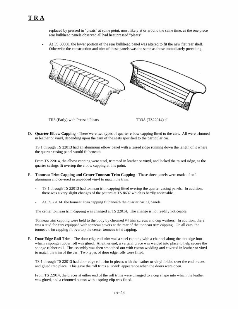
T R A
IN-24
replaced by pressed in "pleats" at some point, most likely at or around the same time, as the one piecerear bulkhead panels observed all had heat pressed "pleats".
- At TS 60000, the lower portion of the rear bulkhead panel was altered to fit the new flat rear shelf.Otherwise the construction and trim of these panels was the same as those immediately preceding.
TR3 (Early) with Pressed Pleats TR3A (TS22014) all
D. Quarter Elbow Capping - There were two types of quarter elbow capping fitted to the cars. All were trimmedin leather or vinyl, depending upon the trim of the seats specified to the particular car.
TS 1 through TS 22013 had an aluminum elbow panel with a raised ridge running down the length of it wherethe quarter casing panel would fit beneath.
From TS 22014, the elbow capping were steel, trimmed in leather or vinyl, and lacked the raised ridge, as thequarter casings fit overtop the elbow capping at this point.
E. Tonneau Trim Capping and Center Tonneau Trim Capping - These three panels were made of softaluminum and covered in unpadded vinyl to match the trim.
- TS 1 through TS 22013 had tonneau trim capping fitted overtop the quarter casing panels. In addition,there was a very slight changes of the pattern at TS 8637 which is hardly noticeable.
- At TS 22014, the tonneau trim capping fit beneath the quarter casing panels.
The center tonneau trim capping was changed at TS 22014. The change is not readily noticeable.
Tonneau trim capping were held to the body by chromed #4 trim screws and cup washers. In addition, therewas a stud for cars equipped with tonneau covers at the rear of the tonneau trim capping. On all cars, thetonneau trim capping fit overtop the center tonneau trim capping.
F. Door Edge Roll Trim - The door edge roll trim was a steel capping with a channel along the top edge intowhich a sponge rubber roll was glued. At either end, a vertical brace was welded into place to help secure thesponge rubber roll. The assembly was then smoothed out with cotton wadding and covered in leather or vinylto match the trim of the car. Two types of door edge rolls were fitted.
TS 1 through TS 22013 had door edge roll trim in pieces with the leather or vinyl folded over the end bracesand glued into place. This gave the roll trims a "solid" appearance when the doors were open.
From TS 22014, the braces at either end of the roll trims were changed to a cup shape into which the leatherwas glued, and a chromed button with a spring clip was fitted.

T R A
IN-25
G. Scuttle Edge Roll Trim - The aluminum scuttle edge roll trim was covered in leather or vinyl to match the trimspecification, and held to the scuttle by #4 chromed trim screws and cup washers, and the tonneau fixing studs.
From TS 6157, a scuttle vent was introduced, and the control cable ran through the scuttle edge roll at thecenter.
The scuttle edge roll trim was changed at TS 22014, but no details are available.
H. Draught Excluder or Windhose - Two types of door edge seals were fitted to the interior of the cars.
- TS 1 through TS 22013 had draught excluders made of 1/4" piping covered in vinyl to match the trim. Thevisible ends were neatly folded in and glued. The rear piece was tacked or stapled to a cord pressed intothe inner dogleg panel. The front was held by the carpet screws.
- From TS 22014, the vinyl piping was replaced by a "fuzzy" seal. Colors and method of attachment werenot changed.
I. Trunk Millboard - The trunk millboard (rear petrol tank casing) was "pebble grained" and held to the car by#4 trim screws and washers. Initially, these panels were sprayed to match the body color of the car. From TS22014, the millboards were all black.
J. Small Fittings - Some of the small interior fittings that are of significance are listed and described below.
1. Door Sill Edge Finishers - These were lightly polished aluminum capping that covered the seam betweenthe inner and outer sills. They were attached by #4 slotted screws without washers.
2. Jacking Hole Covers - The earliest TR2's had a metal jacking hold cover painted body color that twistedoff by rotating. Later, a rubber plug was fitted instead.
3. Trunk Drainage Tubes - The trunks of all cars were fitted with tow short, slightly curved metal tubeswhich ran from a hole in each lower rear corner of the trunk lid channel. To these tubes, a rubber hose waspush fitted, which ran through a hole in the trunk floor.
4. From TS 3268, a similar drainage arrangement was fitted to the battery tray, and ran through the gearboxcover. This tube and hose is visible from inside the car.
5. Spare Tire Stowage Straps and Toll Stowage Straps - These leather straps and buckles were generallyblack, although some colors may have been available. The straps with the buckles were fitted to the floorof the spare tire carrier. The metal fixing loops were painted black, the loose hardware, natural.

T R A
IN-26
Interior - ToolsVIII. Tools
The following tools are required for concours:
Trunk and Tools Item CommentsTools - All cars Jack & handle/ratchet
Coach keyInstruction book part # 501528.
Tools- Disc wheels WheelbraceNave plate removal tool Combination Tool, part # 1398
Tools-Wire wheels Knockoff hammer
Note: Coach Key, Instruction book, and Nave plate removal tool were added to the requirements in 1995.
A. Jack and Jack Handle - All cars were issued a jack.
TS 1 through TS 5468 had a one piece, "open screw" type jack painted black or orange red.
From TS 5469, a tube like "closed screw" jack was fitted with a separate ratchet handle. The jacks wereusually painted varying shades of orange red, and the feet of these jacks were blued or black-oxide finished.The ratchets were blued or painted black.
B. Wheelbrace or Knockoff Hammer - Depending on whether the car was fitted with wire or disc wheels, thefollowing were issued.
- Disc wheeled cars were issued a wheelbrace (lugnut wrench) which was painted gloss black except a bluemetallic painted area inside the socket. Disc wheeled cars were also issued a clear cadmium plated naveplate removing tool. This device was a tommy bar with a screwdriver head on one end and a hooked spoonon the other.
- Wire wheeled cars were issued knockoff hammer, which was either copper or lead. Thor hammers beingreproduced today are perfectly acceptable.
C. Full Tool Roll (Optional) - There is considerable uncertainty as to exactly what the status of the full toll rollswas. Some reference material list these as standard, others as optional, and others as a mix of the two. In theinterest of consistency, I am listing the tool roll as specified by the parts manual (factory) and those componentsI have observed to be in every roll.
These tools include:
1 open end spanner 3/8" x 7/16" A/F1 open end spanner 3/4" x 5/8" A/F1 open end spanner 1/2" x 9/16" A/F1 tube spanner 1/2" x .56" A/F1 sparking plug tube spanner1 pair slip joint grips (pliers)1 Tommy bar (omitted on disc wheel cars)1 cabinet type screwdriver (omitted on disc wheel cars)1 adjustable wrench1 greasegun (Tecalimit #GB 2801)1 feeler gauge assembly1 distributor tool (Lucus key like feeler gauge)1 brass valve stem removing tool1 headlamp rim removing tool (blued or natural sheetmetal) for cars after TS32585.

T R A
IN-27
The toolsets undoubtedly varied from time to time, but the above listing is the most representative. Some othertools encountered are tire irons (early cars) and a small bolt used to pull the front hub dust seals.
All tools, with possibly the exception of very early ones, were finished in clear cadmium, except the following:
- Greaseguns were painted blue metallic hammertone or bronze metallic. The potmetal caps werenatural, as was the shaft. The nozzle was clear cadmium.
- The screwdriver blade was slotted, and natural. The grip was light hardwood.
- The brass valve stem remover was natural.
The tool roll may have initially been rubber or plastic coated jute, but was eventually standardized to a thinplastic/vinyl with heat pressed tool pockets. The tie straps were either white or black cotton.
* As there is no clear way to determine whether a car was originally equipped with a full tool roll, and whichof the above tools were provided, judges are advised to use caution before deducting points for anincomplete tool roll. Obviously, if only three or four tools are shown, the set is incomplete, but beyondthat, be careful.
D. Starting Handling - This optional tool was provided with many cars. There were two types fitted, one forthose cars built up to TS 22014, and one for those built after. They differ only slightly in the position of theboss which slips into the starting handle guide, and by the alignment of the teeth at the end. All were finishedgloss black.
E. Coach Key - All models use the same basic coach keys. There are slight variations in length. The grip sectionshould be straight, not dogbone-like. Finish is natural metal.

Chassis
Table of Contents.
Introduction 2Acknowledgements 2Revision History 2References 2
Chassis Judging. 3...4Chassis Scoresheet 5Chassis Deduction Guide 6
Chassis Originality Guide 7Chronological Summary of Changes 7Chassis 8Exhaust System 8Fuel and Brake Line Routing 8Front Brakes, Suspension, and Lower Steering 9Rear Brakes, Suspension, and Rear Axle 9Propellor Shaft, Transmission, and Road Wheels 10Wheel Arches and Underbody Panels 11A Note on Accessory Items 11A Note on Hardware 11

T R A
CH-2
Chassis - Introduction
This guide is intended to serve as reference for judges in TRA concours events and for TRA members doingrestorations. The material presented is the result several years of assembling information from factory referencematerial, TRA members expertise, TRA judging school reviews and comments, and other Triumph history andreference material.
Editor's note: This section on Chassis will be used for the first time in 1993. It has not yet had the benefit of reviewby members and practical use by judges. Previously, Chassis judging material did not exist. As Chassiscontributions to the total score have been and still represent a relatively small portion of the total score, it has notbeen very controversial. You will find that John has oriented this section more toward the restorer and the judgingguidelines are somewhat more flexible that in other sections. Like other sections, this section can be expected toevolve in depth and usage over time.
Acknowledgements.
Authors and principal contributors: John Warfield (Mason Dixon/TRA). Other reviewers and contributers: Joe Richards and John Gabel (COCTRA)
Revision History.
January 1993 - Initial Version.
References.
The following are referenced where appropriate within. The abbreviations enclosed in parens are used to identifythe associated reference.
(SPCEd1) Triumph Sports Car Spare Parts Catalogue, Edition 1. Part No. 501653/USA.(SPCEd2) Triumph Sports Car Spare Parts Catalogue, Edition 2. Part No. 501653/USA. (SPCEd3) Triumph Sports Car Spare Parts Catalogue, Edition 3. Part No. 501653/USA. (SPCEd4) Triumph Sports Car Spare Parts Catalogue, Edition 4. Part No. 501653/USA. (HWC) Stanpart Hardware Catalogue for use with Standard Triumph Vehicles. Publication part
number 514264.(TSOAHb) Triumph Sports Owners Association Handbook, 2nd Edition.
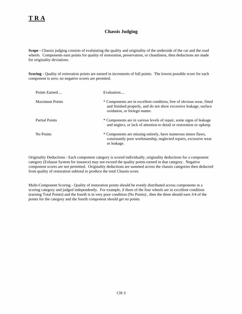
T R A
CH-3
Chassis Judging
Scope - Chassis judging consists of evalutating the quality and originality of the underside of the car and the roadwheels. Components earn points for quality of restoration, preservation, or cleanliness, then deductions are madefor originality deviations.
Scoring - Quality of restoration points are earned in increments of full points. The lowest possible score for eachcomponent is zero; no negative scores are permited.
Points Earned.... Evaluation....
Maximum Points * Components are in excellent condition, free of obvious wear, fittedand finished properly, and do not show excessive leakage, surfaceoxidation, or foriegn matter.
Partial Points * Components are in various levels of repair, some signs of leakageand neglect, or lack of attention to detail or restoration or upkeep.
No Points * Components are missing entirely, have numerous minor flaws,consistantly poor workmanship, neglected repairs, excessive wearor leakage.
Originality Deductions - Each component category is scored individually, originality deductions for a componentcategory (Exhaust System for instance) may not exceed the quality points earned in that category. Negativecomponent scores are not permitted. Originality deductions are summed across the chassis categories then deductedfrom quality of restoration subtotal to produce the total Chassis score.
Multi-Component Scoring - Quality of restoration points should be evenly distributed across components in ascoring category and judged independently. For example, if three of the four wheels are in excellent condition(earning Total Points) and the fourth is in very poor condition (No Points) , then the three should earn 3/4 of thepoints for the category and the fourth component should get no points.

T R A
CH-4
Quality of Restoration Inspection
The inspection should include but is not limited to the following areas:
Presentation .... Flaws....
Installation * Fitting of components is lacking in neatness, do not fit properly asdesigned.
* Components are visibly loose.
Appearance of Components * Components are finished poorly, or neglected as to finish.* Components are leaking or covered in leakage from another
component.* Components are oxidized heavily. Tires worn. * Underpanels are heavily undercoated, filthy, or have indications of'
poor body work.* Components, though neat, show signs of unrepaired collision
damage.
Condition of Fittings and Sundry Parts * Small fittings such as clips, exhaust hangers,fuel lines, nuts andbolts are excessively dirty, pitted, oxidized.
Caution: You may not remove or disassemble components for inspection. Avoid touching the car orcomponents if possible.
General Evaluation and Scoring Guideline . The inspection should be done from the point of view that the carshave been driven, and that some components cannot remain in showroom quality indefinitely. For example, a mildsteel exhaust system will oxidize virtually overnight, and only scaling or serious fatigue should be cause forconcern. Better than new condition found on some components should not earn more or less points than acomponent in "new" condition. Again, for example, components finished to a high standard in gloss black shouldnot be given greater consideration than components finished neatly, but to a stock level. Extreme over restoration,however may result in originality deductions. For example, chrome plated suspension components or a mirror-polished, stainless steel, exhuast may result in originality deductions.
The weight given to the deductions for some originality faults were delibertly set low in this section to reflectreasonable alterations or updates to improve the cars' roadability withthout violating the "spirit" of the marque. Forexample, only 5 points are deducted for TR2s fitted with the more sensible TR3A exhaust.

TRA
Category Originality Deductions Quality Quality OriginalityPoints Earned Deductions
Chassis 10 pts 5 pts 2 pts 15Frame Incorrect assembly Finish 10Radiator Crosspiece Incorrect component Finish 5
Exhaust System 10 pts 5 pts 2 pts 10Exhaust System factory type (number and
size of silencers)exhaust attachment hardwareFinish 5
Tailpipe extension Incorrect or nonperiod Finish 5
Fuel & Brake Lines 5 pts 2 pts 1 pts 5Fuel Lines Incorrect lines Incorrect routing Finish 2
Mounting HardwareBrake Lines Incorrect lines Incorrect routing Finish 3
Mounting Hardware
Front End 10 pts 5 pts 2 pts 10Brakes Lockheed vs. Girling Finish 3Suspension non-period mod Finish 4Lower Steering non-period mod Finish 3
Rear End 10 pts 5 pts 2 pts 10Brakes Incorrect assembly Finish 3Suspension Incorrect assembly non-period mod Finish 4
Mounting HardwareRear Axle Assembly Mayflower vs. Vanguard non-period mod Finish 3
Drive Train 8 pts 4 pts 2 pts 8Propellor Shaft Incorrect assembly Finish 3Transmission Incorrect assembly LO car but no overdrive Finish 5
Road Wheels 8 pts 4 pts 2 pts 32Wheel Incorrect assembly Finish 8
Hub caps & world Incorrect component Finish 8Wire wheel knockoffs Incorrect component Finish 8
Tires Non period 8
Oher 5 pts 3 pts 2 pts 10Wheel Arches Incorrect Panels Incorrect baffle, seals Finish/Coating 5Underbody Incorrect Panels Incorrect jack hole or plugs Finish/Coating 5
Total Quality pts earned and subtract originality deductions Total possible 100
CH Total
Judges' Annotations Key: Circled item = Originality deduction Underlined item = Quality deduction
Chassis ScoresheetEntry:
Commission #:
Owner:
Model/year:
CH-5

TRA
Blank Page
CH-5

T R A
CH-7
Chassis Originality Guide
As in other sections, judges and restorers alike should recognize that even the most well documented changes aresubject to a significant margin of error due to the mass production processes used in TR assembly. Referenceinformation should not be considered the absolute "gospel". Unless otherwise extended for specific components, amargin of error of 100 commission numbers should be used throughout.
For your convenience, the Originality Guide is organized in outline form according to the components listed on thescoresheet and deductions guide. Engineering changes are noted in each section when appropriate. A summary ofchanges is provided below.
Chronological Summary of Chassis Changes
TR2
TS? January 1954. Wire wheels become optional.TS 1869 Disc wheels upgraded from 4J to 4.5J.TS 2532 Exhuast silencer increased to 24 inches long.TS 3175 Rear Spring change.TS 3512 Radiator protection crosspiece fitted.TS 4310 Infill stiffening plates fitted to chassis. Exhaust mounting altered.TS 4699 Frame bracket for rear shock changed.TS 5443 Rear brakes increased to 10 inches diameter.TS 5777 Steering brace added from column to chassis crosstube.
TR3
TS 9122 Front, lower suspension, A-frame bearings are changed to nylon with steel sleeves.TS 11385 Rear silencer added to exhaust.TS 13046 Brake system now Girling disc. Rear axle to Vanguard type. Bolt on hub extensions for
wire wheels.TS 15497 Fuel line routing around fuel shutoff tap simplified. Fuel tap supposedly eliminated.TS 15706 Tailpipe changed. Possible change from chrome to polished aluminum exhaust finisher.
TR3A
TS 22014 Stiffening bracket added between trunnion and bumper mounting bolt. Disc wheels nowsprayed silver.
TS 26904 Softer rear spring fitted to passenger side.TS 27689:27858 Disc break dirt shield added.TS 56377 Rear brakes reduced in diameter to 9 inches. Introduction of Girling "B" type split
caliper in front for wire wheel cars .TS 56384 Introduction of "B" type caliper on disc wheeled cars.TS 60001 Change in body tooling neccessitates change in gas tank design and fuel line routing.

T R A
CH-8
I. Chassis
A. The chassis may be painted black, or any body colour contemporary with the production date of the car.
B. There were several modifications to the chassis during the production run. For the purposes of judging, theseare the most important:
At TS3512, a radiator crosspiece was added to protect the vulnerable lower tank. This piece is finished inblack.
At TS4310, the chassis was stiffened by infill plates at the center of the "X" frame.
At TS4699, reinforcing plates were added to the rear shock mounting brackets (ref. Service Bulletin, November1954).
II. Exhaust System
A. The exhaust systems on the TR2-3B were mild steel, initially sprayed in black paint, then at some point, in dullsilver. This finish was of no value except in keeping the exhaust components from rusting during pre-assemblystorage. Make no deductions for black dull silver, natural mild steel, or stainless steel of correct configurationand in good order.
B. There were several modifications on the exhaust systems:
At TS2532, the very noisy 18 inch muffler was replaced with a 24 inch one.
At TS4310, the forward mounting assembly was altered to accomodate the new chassis improvements.
At TS11385, a second silencer was added to the rear of the system to further reduce noise.
At .TS15706, the tail pipe and tail pipe extension was changed. This could be from a chrome finished tip to apolished aluminum one.
III. Fuel and Brake Line Routing
A. Brake and fuel lines were usually left bright, with the fittings, steel or brass, bright also. The clips holding thelines to the chassis were usually finished black.
B. The two major changes in brake and fuel line routing occurred at TS13046, when the brake system was changedto Girling with front disc brakes, and at TS 60001, when the change in body design required a change inrouting around the petrol tank.
In addition, there was a change in fuel line routing around the fuel shutoff tap to a simplified push fit 1ine. Atsome point, the fuel valve was deleted entirely, but it is believed much later. (See Underhood's section on FuelSystem).
Judging Note: Make no deductions for brake line routing if the lines are run consistent with a substitutedbraking system (Lockheed vs. Girling). Judging of lines in the engine comparment are covered in Underhood;lines from the fire wall and back are covered here in addition to the brake lines at the front disc calipers.

T R A
CH-9
IV. Front Brakes, Suspension, and Lower Steering Details
A. The drums of Lockheed equipped cars were painted black. The brake lines and mounting hardware were left inthe manufacturers finish, bright, natural, or black oxide.
At TS 9122 the rubber bushes in the lower control arms were replaced with nylon bearings with steel sleeves.Upgrades to earlier cars are acceptable.
At TS 13046, the Lockheed drums were replaced with Girling discs. The disc caliper assemblies and rotorswere left unfinished, although no deductions should be made for calipers and rotors finished in a manner thatapproximates natural metal.
At TS27689 (wire wheel) and TS27858 (disc wheel) , dirt shields were added to the disc brake units (Ref:TSOAHb, pg 115).
At TS56377 (wire wheel) and TS 56384 (disc wheel), the front caliper assemblies were replaced by the smallerand more efficient Girling "B" type split caliper. These were also left in natural metal.
B. The suspension components were usually painted black. Bushings, rubber components, and spring packingswere left natural. Shock absorbers may be found in different colours depending upon the supplier, usuallyblack or blue. Assembly and identification marks may be present on some components.
C. The lower steering components were, as can be expected, painted black. Some steering idlers may have beenleft unfinished cast metal. Some markings are possible.
At TS5777, a brace was added from the steering column to the chassis crosstube.
At TS22014 a stiffening bracket was added between the lower steering trunnion bracket and the bumpermounting bolt.
D. As noted earlier, mounting hardware was not sprayed over (that is, it was not assembled and painted but paintedand then assembled) and should be left in the manufacturers finish. Black oxide (or similar) is recommendedfor "Grade 8" bolts and setscrews, while natural or clear cadmium for others. No deduction should be made foreither finish, or stainless steel, if the hardware is clean and presentable.
V. Rear Brakes, Suspension, and Rear Axle Assembly
A. The external surfaces of the rear brakes, suspension, and axle assemblies were usually painted black. Earlyshock absorber bodies may be found in natural metal. Some markings are possible.
At TS3175, the front portion of the rear springs were stiffened "to meet the demands of rally conditions" (Ref:Service Bulletin, Feb 1955). The early version had but one clip fitted to the forward end of the spring; themodification introduced a second clip. Retrofitting of the newer springs on older cars is acceptable; later carsshould not be fitted with the early versions however.
At TS5443 the rear brakes were increased in diameter from 9 to 10 inches.
At TS13046, the braking system was changed to Girling and the rear axle was replaced with the sturdier"Vanguard III" design. The major visual difference between the two is at the outboard ends of the rear axlecasings, the earlier unit has a squared off flange with four mounting bolts, while the later is round and has sixmounting bolts. Markings may be present.
At TS26904, the passenger side rear leaf spring was replaced with a slightly softer one to accommodate theincreased wear on the driver's side. Markings may be present.

T R A
CH-10
At TS56377, the rear brakes were decreased from 10 to 9 inch diameter.
VI. Propellor Shaft, Transmission, and Road Wheels.
A. The propellor shaft was painted black. Universal joints could be black or natural. The sleeved yoke end of thepropellor shaft should be mounted forward, on the transmission end.
B. The transmission casing is natural aluminum. If painted and deductions have already been made, make nofurther deductions on this point. The transmission should be clean, reasonably free of leaks, or other road filth.Cars with L commision numbers may be refitted with overdrive units; cars with LO commision numbers shouldbe equipped with overdrive units.
C. The road wheels initially fitted to the TR2 were 4" disc wheels painted the body color of the car, black possiblyon very early cars.
1. In January, 1954, wire wheels were first offered as an option. The wheels were 48 spoke Dunlops andnearly allways finished in "Dunlop Wheel Silver" paint, although bright chrome, dull chrome,aluminum, and lacquer are listed in the parts book. Heavier 60 spoke wire wheels were also offeredas an option, presumably with the same range of finishes. Make, no deductions for any of thesefinishes, or types of wire wheel. Please also note that wire wheels may possibly have been suppliedfinished the body color of the car or refinished by dealers, and athough such a finish is very rare atbest, it could be possible. Knockoffs are two eared, and finished in chrome.
2. At TS1869, the 4"disc road wheel was replaced with a 4.5 inch wheel of the same basic design.Earlier cars may be retrofitted with the wider wheel, which is much less likely to shatter. Take nodeductions for very early TR2's fitted with the 4.5 inch rims.
3. At TS22014, the early "hub, peg, and collar" wire wheel attachment arrangement was replaced with asimpler, bolt on adaptor and shorter lug nuts. The disc wheels on cars built after TS22014 weresupposedly finished in "Dunlop Wheel Silver" instead of to match the car, but road wheels painted inbody colour have been known to have been fitted to much later cars. Again, dealers may have donethis on their own. Make no deductions for either finish.
4. At TS13046, the knaveplate, "hubcap", medallions supposedly changed from an enamelled to apainted finish. Enamelled badges in fact were fitted to much later cars. Make no deduction foreither badge on post TS13046 cars (disc brake change).
D. The tires fitted to the earliest TR2s were 550 series, bias-ply, Dunlop blackwalls.Later,Michelin "X" seriesradia1s, whitewalls, and 590 series bias-ply Dunlops in both blackwall and whitewall style were offered. Mostall but the earliest TR3As were fitted with 590 or Michelin tires. For the purposes of judging, all are correct,including 560 series whitewalls -- no 550 whitewalls are available currently. If whitewalls are installed, theyshould be of the period, typically 2 to 3 inches wide. As tires are consumables and older tires are a safetyhazard, judges should accept tires that are comparable replacements to the originals (for example, a wide plytire would not be comparable to a Michelin 590 but a similar sized radial from a Michelin competitor would becomparable). Restorers are of course encouraged to fit tires as close to the original specifications of their carsas possible.

T R A
CH-11
VII. Wheel Arches and Underbody Panelling
A. The wheelarches of sidecurtain TRs were sprayed in body colors, including the bulkhead sealer plates andrubber seals on cars fitted with PVC wing beading. Later cars may have had these attached later in assemblyand finished in black paint and left natural, respectively. In addition, a thin spray of Waxoyl or other similartypes of undercoating has been found running along the underside seam between the fenders and innerwheelarch sections of the main body tub. This has mostly been encountered on TR3As. Make no deductionsfor the presence or absence of this undercoating.
B. The underside of the body tub was sprayed body color and generally was not sprayed with masses ofundercoater. On later cars, plastic drain plugs were fitted to the holes in the underbody, and were leftunpainted.
VIII. A Note on Accessory Items.
A number of high speed and handling accessories were available to the TR enthusiast when the cars were new, bothfrom the factory and from a host of aftermarket suppliers. Make no deductions for the presence of these items, aslong as they are consistent wtih the period of the cars' manufacture. Some of these items include:
Front anti-roll bars Aluminum SumpTorsion bars Rear wheel spatsUndershield Kit Rim embellishers (trim rings)Uprated shock absorbers Skid-plateStiffer front springs
IX. A Note on Hardware
The manufacturers of the various nuts and bolts that were used on the sidecurtain TRs were many and some of thefinishes no doubt varied. A general rule on undercarriage hardware is that bolts and "Grade 8" setscrews were mostoften finished in black oxide industrial finish, not the gold cadmium used later in the 1960s. Some castle nuts andstandard pattern nuts may have been black also. Nyloc nuts were usually finished bright. Judges are not to makedeductions for consistency, as consistency didn't always exist. Neatness and safety take precedence on this one.

TRA
Blank Page

TRA
Area Points Unadjusted Weight AdjustedScore Score
Exterior 100 x 0.4 =
Underhood 100 x 0.2 =
Interior 100 x 0.25 =
Chassis 100 x 0.15 =
Grand Total (100)
Computing Score:1. Record scores from area worksheets in "Unadjusted Score" columns.2. Multiply "Unadjusted Score" for each area by the "Weight" for that area.3. Round result to nearest 100th point (eg., 12.345 is rounded up to 12.35) and record
in "Adjusted Score".4. Compute Grand Total as sum of "Adjusted Scores" from each of the judging areas.
A perfect score would be 100.
Master ScoresheetEntry:
Commission #:
Owner:
Model/year:


