239
TRL ACADEMY REPORT PPR875 Electric Road Systems: a solution for the future D Bateman, D Leal, S Reeves, M Emre, L Stark, F Ognissanto, R Myers, M Lamb

TRL ACADEMY REPORT PPR875
Electric Road Systems: a solution for the future
D Bateman, D Leal, S Reeves, M Emre, L Stark, F Ognissanto, R Myers, M Lamb

ERS: a solution for the future?
2
Report details
Report prepared for: TRL Academy
Project/customer reference:
Copyright: © TRL Limited
Report date: 8th October 2018
Report status/version: 1.0
Quality approval:
C Booth
(Project Manager)
T Barlow
(Technical Reviewer)
Disclaimer
This report has been produced by TRL Limited (TRL) under a contract with TRL Academy. Any views expressed in this report are not necessarily those of TRL Academy.
The information contained herein is the property of TRL Limited and does not necessarily reflect the views or policies of the customer for whom this report was prepared. Whilst every effort has been made to ensure that the matter presented in this report is relevant, accurate and up-to-date, TRL Limited cannot accept any liability for any error or omission, or reliance on part or all of the content in another context.
Contents amendment record
This report has been amended and issued as follows:
Version Date Description Editor Technical Reviewer
0.1 13/07/18 Interim report – Task 1 only DL, DB, ME, SR
0.2 31/07/18 Full draft report – all tasks for technical review DL, DB, ME, SR, FO, LS, RM, ML
TB
1.0 04/09/18 Final report taking into account TR comments DL, DB, SR, PV
TB
Document last saved on: 13/11/2018 12:27
Document last saved by: Leal, Dominic

ERS: a solution for the future
Final i PPR875
Executive Summary
It is looking increasing likely that electric vehicles will play a major role in the future of road transport. While commercial electric vehicles exist their uptake has been limited due to high purchase costs, limited battery range, and a lack of charging convenience. Furthermore, while developments are underway, electric and hybrid drive trains are yet to be efficiently integrated with heavy goods vehicles (HGVs). A novel way to overcome such challenges are Electric Road Systems; a branch of technologies that allow vehicles to charge while in motion. ERS technologies are currently in development, with limited information available to road authorities regarding the comparative performance of ERS solutions, market readiness, costs, and implementation issues. In this reinvestment project funded by the TRL Academy a state-of-the-art review and feasibility study of ERS concepts; focusing on ERS implementation from the perspective of a UK road administration was undertaken. This reinvestment project was completed in parallel with the World Roads Association/PIARC funded project ‘Electric Road Systems – A Solution for the Future?’.
The study had three interlinked phases:
(1) state-of-the-art review and stakeholder engagement,
(2) technological and implementation feasibility assessment, and
(3) cost-benefit analysis for ERS uptake.
The study adopted a global perspective, engaging with key stakeholder (road administrations, researchers, ERS developers, freight industry) from different countries through an online survey and interviews with relevant experts. This informed the review, highlighting stakeholder views on benefits, limitations and barriers to development/implementation. A total of 17 viable ERS systems were identified. These are split into three categories: inductive (wireless); conductive rail; and conductive overhead. The majority of inductive ERS have a technology readiness level (TRL) between TRL3-4; with few systems advancing beyond TRL6. Conductive counterparts are more mature, typically between TRL4-5, with some systems between TRL6-8. All three types of ERS are undergoing road trials of some form, with rapid advancements in the last 5 years. All three concepts are technologically feasible, providing comparable and unique advantages/limitations. For instance, conductive systems are more able and ready to support the power requirements of heavy goods vehicles. Whereas inductive ERS are generally more suited to vehicles with lower power requirements, and cannot deliver at efficiencies equal to conductive systems. Risk assessments of each technology were undertaken, with results suggesting the majority of risks are ‘low to very low’. Conductive rail solutions however were inherently more risky due to: the presence of an open live conductor on high speed roads; and their impact on road maintenance activities. Concerns arise over the impact of any type of system that is integrated into the pavement structure, regarding durability, future maintenance and safety. Interoperability, within and across ERS categories does not currently exist.
Stakeholder engagement results suggest that despite uncertainties regarding ERS performance and barriers to implementation, the majority viewed the technologies positively and believed that ERS would be key to decarbonising road transport.

ERS: a solution for the future
Final ii PPR875
Approximately half of the survey participants were actively involved in ERS research (from desktop studies to road trials). The majority of research is being undertaken in Europe, South Korea, Japan and the USA. Discussions with road administrations and developers emphasised that different ERS concepts should be viewed as solutions for given scenarios, rather than as ‘rivals’. Instead, the overall aim of all solutions is to better improve the sustainability of road transport networks and mitigate current levels of environmental impact. Stakeholders identified freight industry and public transport operators to be the likely first adopters of ERS. Stakeholders identified the key barriers to implementation as being high capital cost (for installation, maintenance and administration), alongside the risks associated with relatively immature technology. A key message from stakeholders was that government support is critical to ERS development and in addressing industry concerns.
The bulk of current research is focused on functionality and installation. However other aspects required further attention, such as economic viability and the development of attractive business models. The study presents a UK specific cost-benefit analysis for a case study motorway. Assumptions, based on Phase 1 and 2 findings, were made on installation prices, technology take-up, and vehicles types suitable for ERS concepts. The results suggested that some types of ERS could be economically viable with sufficient electricity mark-up and technology penetration. However, there needs to be a clear understanding of who the main customer basis is. The ERS concept type affects the potential market, as the conductive overhead system can only be used by taller vehicles such as HGVs and buses, whilst in-road systems could be used by both light vehicles and HGVs. However for light vehicles, ERS would be competing with other charging solutions; it is likely that private EV owners will use mainly plug-in or static charging solutions. Advances in other low carbon technologies, such as bio-fuels, fuel-cells, and electric batteries may also influence the take-up of ERS. As yet there is no clear evidence to suggest that it would either promote or limit ERS implementation. With respect to delivery, it is still unclear as to where the responsibility for ownership and operation of ERS technology should fall. It seems most likely that some form of private public partnership would be needed for implementation. This will require modifications to the existing regulatory framework and concessions between road administrations and operating contractors.
Overall the study concluded that ERS has the potential to play a major role in the decarbonisation of road transport, but in the short term is most likely to be adapted by specific parties to meet localised needs rather than a universal solution.
Recommendations for road administrations are provided in two stages:
(i) intermediate steps for ERS implementation which include: identifying potential routes for ERS implementation; identifying relevant standards and policy that require modification in order to plan future integration; to participate in international forums and technical committees; and to share knowledge with international road administrations and research organisations;
(ii) long term objective should be to support and take part in road trials that aim to better understand the benefits and impacts of ERS for a given transport network.
Detailed recommendations are also included for freight industry actors, government and researchers.
ERS: a solution for the future
Final iii PPR875
Contents
Executive Summary i
1 Introduction 4
1.1 Background 4
1.2 Objectives 5
1.3 Scope 5
2 Methodology 7
2.1 Task 1 activites 7
2.2 Task 2 activities 9
2.3 Task 3 activities 10
2.4 Conclusions and recommendations 10
3 Task 1: Description of ERS developments, TRL and key players 11
3.1 ERS concepts 11
3.2 Stakeholder Perspectives 20
3.3 Task 1 Summary 31
4 Task 2: Comparison of different ERS technologies 34
4.1 Technological feasibility 34
4.2 Impact on infrastructure and maintenance 37
4.3 Safety and security 37
4.4 Regulatory framework and standards 39
4.5 Risk Assessment 43
5 Task 3: Business models and cost-benefit analysis from a road administrations perspective 47
5.1 Understanding the market and competition 47
5.2 Revenue sources 48
5.3 Actors and drivers 49
5.4 Types of Business Model 49
5.5 Cost-benefit analysis 50
5.6 CBA results summary 52
5.7 Task 3 Conclusions 58
6 Study conclusions 60

ERS: a solution for the future
Final iv PPR875
6.1 Technological feasibility 60
6.2 Stakeholder perspectives 60
6.3 Advantages, disadvantages and challenges 61
6.4 Economic feasibility and business models 62
6.5 Summary statement 62
7 Recommendations 63
7.1 Road administrations 63
7.2 Researchers 65
7.3 Freight Industry 66
8 Acknowledgements 68
9 References 69
Appendix A: Staeholder Engagement
Appendix B : ERS Case Studies
Appendix C: ERS Risk Assessment
Appendix D: ERS Summary Sheets
Appendix E: ERS Cost-Benefit Analysis
Appendix F: Bibliography

ERS: a solution for the future?
1
Glossary
Term Definition
AADF Average Annual Daily Flow
AC Alternating Current
APS Aesthetic Power Supply
B Magnetic Field
BM Business Model
BMS Battery Management System
CAN Controller Area Network
CBA Cost Benefit Analysis
CO2 Carbon Dioxide
CRF Centro Ricerche Fiat
CWD Charge While Driving
DBFO Design Build Finance Operate
DC Direct current
DEFRA Department for Environment, Food and Rural Affairs
DWPT Dynamic Wireless Power Transfer
eBus Electric Bus
EC European Commission
ECU Electronic Control Unit
EFC Emissions Forecasting Tool
EM Electromagnetic
EMC Electromagnetic Compatibility
EMF Electromagnetic Field
EMI Electromagnetic Interference
ERS Electric Road System
EU European Union
EV Electric Vehicle
FOD Foreign Object Detection
FP7 EU Seventh Framework Programme
G Generation
GHG Greenhouse Gas
GBP Great British Pound
GVW Gross Vehicle Weight
HEV Hybrid Electric Vehicle
HF High Frequency
HGV Heavy Goods Vehicles
HPDC High Power Dynamic Charge
ICE Internal Combustion Engine
ICNIRP International Commission on Non-Ionizing Radiation Protection
IEC International Energy Commission
IEEE Institute of Electrical and Electronics Engineers
Imin Inductive Minimum Capital Cost
Imax Inductive Maximum Capital Cost

ERS: a solution for the future
Final 2 PPR875
IPR Intellectual Property Rights
IPT Inductive Power Transfer
IPV Induction Powered Vehicle
KAIST Korean Advanced Institute of Science and Technology
kHz Kilo Hertz
KPH Kilometres Per Hour
kW Kilo Watt
LDV Light Duty Vehicle
LKM Lane Kilometres
LMIC Low and Middle Income Countries
LV Light Vehicles
LWH Length Width Height
Maas Mobility as a Service
MPH Miles Per Hour
N2N Node to Node
NAEI National Atmospheric Emissions Inventory
NIMBY Not In My Back Yard
NO2 Nitrogen Dioxide
NOx Nitrogen Oxides
NPV Net Present Value
NRA Network Road Administration
OBU On-Board Unit
OCC Operations and Control Centre
OEM Original Equipment Manufacturer
OLEV Online Electric Vehicle
Omin Conductive Overhead Minimum Capital Cost
Omax Conductive Overhead Maximum Capital Cost
ORNL Oak Ridge National Laboratory
ORU Other Road Users
PATH Partners for Advanced Transportation Technology
PF Power Factor
PHEV Plug-In Hybrid Electric Vehicle
PM Particulate Matter
POT (PIARC) Project Oversight Team
PV Photo Voltaic
QF Quality Factor
R&D Research and Development
RO Road Operator
Rmin Conductive Rail Minimum Capital Cost
Rmax Conductive Rail Maximum Capital Cost
SMFIR Shaped Magnetic Field in Resonance
SPSE Specific Power Specific Energy Ratio
SRS Static Recharging Solution
SV System Voltage
T Teslas

ERS: a solution for the future
Final 3 PPR875
TAG Transport Analysis Guidance
THD Total Harmonic Distortion
TM Traffic Management
TRL Technology Readiness Level
V2G Vehicle to Grid
V2I Vehicle to Infrastructure
V2V Vehicle to Vehicle
VAT Value Added Tax
VRS Vehicle Restraint System
WB World Bank
WPT Wireless Power Transfer
YTD Years to Deployment

ERS: a solution for the future
Final 4 PPR875
1 Introduction
1.1 Background
In order to keep the global temperature rise below 2°C and avoid the most severe climate change, it was estimated by the Intergovernmental Panel on Climate Change (IPCC) that world-wide emissions of greenhouse gases (GHGs) must be cut by 40% to 70% by 2050 compared to 2010 levels164. As transport, particularly road transport, is a major contributor of GHGs there is a clear need for accelerating the introduction of low carbon vehicles. Although government policies are technology neutral and focus on supporting any technologies that are able to meet their objectives, particular attention has recently been placed on electrified vehicles. For example the European Commission Directive on the deployment of alternative fuels infrastructure165 has particularly high targets for Electric Vehicle (EV) charging infrastructure. At the same time, many of the world’s leading automotive manufacturers are making significant long-term investments into electro-mobility, which are indicative of a growing and maturing market. EVs are being increasingly viewed as having a key role to play in both reducing global carbon emissions and improving local air quality.
Whilst recent improvements have increased battery range and decreased charging time, there remain concerns for users, deterring uptake. One method of addressing this is by utilising dynamic charging or Electric Road Systems (ERS). ERS is defined as a system that provides dynamic electric vehicle charging through either conductive or inductive (wireless) means for various types of vehicles on roads and highways. Dynamic on-road charging also enables the use of electric powered Heavy Goods Vehicles (HGVs) which is currently not feasible with statically charged battery technology (although vehicle manufacturers are working on this). There are a number of different types of ERS technology being developed and trialled, all of which will require the participation of the road infrastructure owners for deployment. Note that for this study, HGVs are defined as commercial vehicles that have a gross vehicle weight (GVW) of over 3,500 kg. Vehicles less than 3,500 kg are referred to as Light Vehicles (LVs).
Each of these systems vary in terms of the type of charging system they employ (static or dynamic) relative to the road surface (overhead catenary, in-road conductive, or in-road inductive), the types of vehicles that can be charged (cars, buses, freight), and the type of pavements that they are installed in (asphalt or concrete). With each system there are challenges and opportunities that require careful planning and consideration. There is a need for road authorities to understand the types of ERS being developed, what each technology means for their network and what role they will need to play in implementation.

ERS: a solution for the future
Final 5 PPR875
1.2 Objectives
This TRL reinvestment project aims to provide relevant stakeholders with a comprehensive summary regarding developments and implementation considerations of ERS technology around the world; focusing on the UK perspective. The report consolidates state-of-the-art knowledge and expert experiences in order to share an understanding of how ERS and can how they can benefit the transport system. In particular, it aims to inform local/central government, and road administrations of the relative feasibility of implementing ERS technologies on their road networks, in terms of: technology readiness level (TRL) and barriers; installation and maintenance; safety and risks; regulation and standards; costs and benefits; and stakeholder perspectives.
Specifically, the report includes:
A description of the state of development of different types of ERS and an estimated timeline for deployment;
A summary of the potential benefits and limitations of each system
An techno-economic and regulatory evaluation of implementation (in the context of rival technology developments);
Proposed recommendations for road authorities and topics for further research.
Other deliverables include an infographic package, presentation slide packages, and an article in Routes and Roads industry magazine.
1.3 Scope
This project focuses on ERS which provide in-motion charging and includes both inductive and conductive technologies. ERS is impacted by developments of other technologies (such as static charging, battery improvements, alternative fuels etc. therefore the study also briefly reviews these in order to present an informed view of ERS potential and limitations.
The project objectives were achieved through the following three tasks:
Task 1: Description of ERS developments, TRL and key players:
Undertake a state-of-the-art review of current systems (based on publicly available information);
Carry out stakeholder engagement activities (online questionnaire, interviews with experts, and a workshop of experts) to inform the state-of-the-art;
Identify the current TRL rating and market readiness;
Identify key players and target markets for near-term implementation.
Task 2: Comparison of different ERS technologies
Assess the advantages and disadvantages of each ERS solution;
Undertake a risk assessment (for installation, use, maintenance and end-of-life).
Task 3: Cost-Benefit Analysis model from a road administrations perspective

ERS: a solution for the future
Final 6 PPR875
Discuss the different types business models for road administrations;
Develop a model to assess economic and environmental feasibility of different solutions (including an assessment of carbon dioxide, nitrogen dioxide, and particulate matter emissions savings).
The report describes the methodology used to carry out these tasks and then summarises the findings from each task. Finally it provides conclusions and recommendations.

ERS: a solution for the future
Final 7 PPR875
2 Methodology
2.1 Task 1 activities
The objective of Task 1 was to conduct a state-of-the-art review on different systems, their TRLs, and the key player involved in the development of these technologies. A literature review was carried out to gather and summarise the most recent information and research findings on ERS solutions from around the world. Information has been consolidated from previous TRL projects and is enhanced through a comprehensive evaluation of journal articles, research project reports, news articles, academic thesis’s, demonstration results, and manufacturer information.
Figure 2-1: ERS development environment
ERS development occurs within a complex sphere of diverse stakeholders; each having
different priorities, needs and concerns (see
Figure 2-1). Capturing the experiences and concerns of informed stakeholders was a key
element of this project; accordingly a set of engagement activities were undertaken in order
to build a clear picture of ERS development. This included an online questionnaire;
telephone interviews, and a workshop of experts to discuss implementation. Interactions
were focused on five primary groups of actors: road administrations and government bodies;
ERS developers; researchers and academics; freight operators; and power suppliers.

ERS: a solution for the future
Final 8 PPR875
40
46
6
17
2 8
NRAs & Government
Researchers & Academia
Freight Industry
ERS Developers
Electricity Suppliers
Other Stakeholders
A survey was published online and was active for 2 months. It had a two-fold purpose; firstly to capture general perceptions and data, and secondly to secure participation for further engagement activities. The project team contacted over 400 informed stakeholders across 55 countries. In total 119 individuals/organisations, from 39 countries, responded to the survey. Figure 2-2 illustrates the origin countries of participants for the online survey. Figure 2-3 illustrates a breakdown of participation by stakeholder group. Note both Figure 2 2 and Figure 2-3 share the same key (presented in Figure 2-3). The majority of responses were from National Road Administrations (NRAs) and Governments, Researchers and Academia, and ERS developers (accounting for 87% of responses); whilst responses from freight industry and electricity manufacturers were limited. The ‘other’ group includes professions such as civil engineers, land-use planners and consultants.
With regards to responses from UK based stakeholders (making up 9% of total survey responses), participation rates were as follows:
NRAs & Government = 1 response
Figure 2-2: online survey questionnaire participation by country
Figure 2-3: online survey participation by stakeholder group

ERS: a solution for the future
Final 9 PPR875
Researchers & Academia = 4 responses Freight Industry = 5 responses Other = 1 response
In addition to the online survey, a number of telephone or video-linked interviews were conducted with key stakeholders. Of the 119 survey participants, 66 agreed to further engagement. These were shortlisted based on expertise, stakeholder group, country of operation, and type of ERS system. The aim of each interview was to provide a forum for richer discussion on ERS developments, benefits and challenges. Interviews were recorded and transcribed for analysis. Interviews were carried out with representatives from the following organisations:
Trafikverket, Sweden (National Road Administration)
Highways England, UK (National Road Administration)
Sanef Group, France (National Road Administration)
National Roads Authority, Uganda (National Road Administration)
SANRAL National Road Authority, South Africa (National Road Administration)
IMT Instituo Mexicano del Transporte, Mexico (National Road Administration)
Scania AB, Sweden (ERS Vehicle Manufacturer)
Siemens AB, Sweden (ERS Technology Manufacturer)
Dongwon OLEV, South Korea (ERS Technology Manufacturer)
Alstom Group, France (ERS Technology Manufacturer)
ElectReon, Israel (ERS Technology Manufacturer)
BASt Federal Highway Research Institute, Germany (Researcher)
J-N-J Miller Design PLLC, USA (Researcher/Consultant for Oak Ridge National Laboratory and Momentum Dynamic Corp.)
2.2 Task 2 activities
The objective of Task 2 was to evaluate the information gathered in Task 1 and compare the advantages and disadvantages of the different ERS concepts. Each ERS concept was assessed in relation to the areas listed below. Based on the information available the perceived advantages, disadvantages, and potential impacts of each system were identified, highlighting the elements relevant to road administrations and LMIC. The main areas for evaluation were:
Technical feasibility and installation challenges; Impact on road infrastructure and maintenance; Safety and security; Environmental and social impacts.
As part of the deployment and uptake evaluation, the project team identified the requirements that could be drivers or impediments to the deployment of each of the ERS. A workshop was also held, attended by 15 experts (from a variety of disciplines including:

ERS: a solution for the future
Final 10 PPR875
intelligent transport systems, e-mobility, infrastructure construction and maintenance, project managers, and sustainability experts. It was mainly formed of TRL experts, but also representatives from the UK’s Department for International Development (DFID) and Oxford Policy Management. The primary objective of the workshop was to discuss ERS implementation in Low-Middle Income Countries (LMIC) – a key theme of the PIARC project. Whilst this report only focuses on implementation in the UK, there were many transferrable findings available in full within the PIARC report found here. The workshop covered 7 key themes: ERS installation and maintenance; impact on road infrastructure and routine maintenance, expertise and equipment requirements; energy supply and reliability; social and environmental impacts; impact of competing technologies; and business cases and operational costs.
The project team reviewed other emerging technologies that could impact ERS development and uptake as part of this task. This included a high level assessment of advances in static charging, alternative fuels (bio-fuels, hydrogen fuel cells), and EV battery improvements. This task also included completing a qualitative risk assessment based on information gathered as part of Task 1. Individual assessments were carried out for conductive overhead, conductive rail, and inductive ERS (all for dynamic charging), alongside assessments for plug-in charging and static inductive charging as a point of comparison. This element considers hazardous events, persons affected, level of concern (very low-very high), and mitigation strategies. This employed a whole lifecycle perspective, from installation to end-of-life.
2.3 Task 3 activities
The objective of Task 3 was to consider the economic feasibility of ERS and the possible business models that could be used to deploy ERS. A cost-benefit model was developed for the UK situation, based on analysis undertaken as part of similar project, to provide estimates of capital, maintenance and administrative costs over a 20 year period per km of ERS installation. The model also produced estimates of environmental impacts (such as tonnes of CO2, NO2, and PM). A series of scenarios were run and analysed exploring different ERS compatible vehicle uptake rates for light vehicle (LVs) and heavy goods vehicles (HGVs), alongside different infrastructure costs and electricity cost mark-ups. Key outputs of the model include payback times for investments, and Net Present Value (NPV) for each type of ERS technology (conductive overhead, conductive rail, and inductive). The Task also considered the potential business models, for example private public partnerships (PPP).
2.4 Conclusions and recommendations
The findings from all three tasks were reviewed and amalgamated to develop conclusions and more importantly specific recommendations for road authorities and researchers with regards to the future implementation of ERS. It should be noted that this report only focuses on conclusions and recommendations from a UK perspective. Full conclusions and recommendations, from a global perspective, can be found in the PIARC report here.

ERS: a solution for the future
Final 11 PPR875
3 Task 1: Description of ERS developments, TRL and key players
This section provides a summary of ERS concepts, systems, developments, TRL ratings, and the key findings from the stakeholder engagement activities. Key parties involved in ERS and their target markets are also described here.
3.1 ERS concepts
ERS is a relatively novel concept that has gathered enormous pace over the last decade. ERS is widely understood as a system that enables dynamic power transfer between a vehicle and the road it is travelling along. Static charging is not considered ERS in itself, but a complementary technology, however many innovations are rooted in static charging systems. Generally, ERS is categorised into three groups:
Inductive (wireless)
Conductive overhead
Conductive rail
Concepts have significant differences between them; however all provide the same function and service – providing on-demand power transfer to EVs whilst travelling at low and normal traffic speeds (quasi dynamic and dynamic, respectively). Depending on the system, power can be stored in batteries for later use (i.e. when not travelling along an ERS installation), or used directly to drive the propulsion unit. Each concept is illustrated in Figure 3-1.
Figure 3-1: Types of ERS; [a] Inductive (wireless), [b] Conductive rail (in-road), [c] Conductive rail (side rail), [d] Conductive overhead

ERS: a solution for the future
Final 12 PPR875
3.1.1 Inductive (wireless)
The concept of inductive ERS is based on the transfer of power from coils embedded in the road (primary) to the coils located in the vehicle (secondary) without any wired connection between vehicle and the road. The power from the grid is converted to high frequency AC power to develop a varying magnetic field, which is picked up by the coil under the vehicle. The magnetic field creates an induced voltage on the pick-up coil and results in flow of electric current on the pickup coils, hence inductive transfer of power.
This type of ERS is contactless and can transfer power across a variable air gap. Generally, inductive systems have three groups of components: in-road, on-vehicle, and roadside. In-road components refer to the primary coils (typically copper litz turnings with a ferrite core) and power cables laid beneath the road surface. In dynamic applications, multiple coils are laid in segments of variable length. On-vehicle components include secondary coil (also referred to as the pick-up unit) and control electronics. In addition the vehicle must have electric drive train components such as battery and electric motor. Roadside components include grid connections, power inverters, transformers, cooling units and communication systems.
Figure 3-2: Inductive ERS concept
Power from the roadside unit is delivered to the primary coil segment automatically when a compliant vehicle, travelling above a certain speed along the track, is detected. The action of the secondary coil passing over the primary coil induces the electromagnetic current between the two and power is transferred. Depending on the system, power can directly drive the propulsion system or charge the vehicles battery. Figure 3-2 provides a simplified schematic of the inductive ERS layout. The principle and components are essentially the same for static applications, however smaller in scale and infrastructural requirements.
Throughout the last eight years the development of inductive systems has grown enormously, with advances being driven a number of factors. These include, but are not limited to, concerns over: climate change impact from road transport, affordability of HEVs and EVs, inconvenience and availability of static charging, range hesitation, battery limitations (costs, size, energy density), rising fossil fuel costs, efficiency of fossil fuel compared to electric drives, local air quality, noise, long term operational savings (relative to fossil fuels), and technological advances /cost reductions of renewable electricity. Table 3-1 provides an overview of inductive systems that have demonstrated dynamic capabilities. It can be seen that all are at various stages of development. Full case studies (containing a

ERS: a solution for the future
Final 13 PPR875
wealth of publicly available information) for each system is available in Appendix B of the full PIARC report.
Table 3-1: Inductive ERS Overview
Name Organisations (Country)
Concept Type Proven
TRL (1-9)
Cost Vehicle Application
OLEV Dongwon Inc. / KAIST (South Korea)
Inductive Dynamic 9 €500,000/lkm197
Buses, LVs, LDVs, Tram/Rail
CWD Politecnico di Torino / CRF (Italy)
Inductive Dynamic 3-4 N/A - Research Project
LVs, LDVs
IPV Seat Group (Italy) Inductive Dynamic 3-4 N/A - Research Project
LVs, LDVs, HGVs, Buses & Shuttles
PRIMOVE Bombardier / Scania (Germany/Sweden)
Inductive Dynamic (under testing)
5-6
€3.25m-6.15m/lkm45 (€1.7m/lkm final expectation)5
LVs, LDVs, Buses
HALO Vedecom / Qualcomm (France/Germany)
Inductive Dynamic 3-4 N/A LVs, LDVs
WPT Oak Ridge National Laboratories / OEM’s (USA)
Inductive Dynamic 3-4 €1.32m/lkm50 LVs
INTIS Integrated Infrastructure Solutions (Sweden)
Inductive Dynamic (under testing)
3-4 N/A Small Plant, LVs
Momentum Dynamics
Momentum Dynamics (USA)
Inductive Dynamic (under testing)
3-4 N/A Buses and Shuttles
Electreon Electreon Inc. (Israel)
Inductive Dynamic 5-6 >€1m/lkm LVs & Buses
Victoria
CIRCE (Centre of Research for Energy Resource and Consumption) (Spain)
Inductive Dynamic 7-8 N/A – Research Project
Buses & Shuttles
WPT University of California, Berkeley, (USA)
Inductive Dynamic 3-4 €1.05m/lkm5 LVs, LDVs, HGVs
3.1.2 Conductive overhead
The conductive overhead ERS is essentially an evolution of overhead rail and trolley bus technologies. This type of system relies on a direct and constant connection (normally using

ERS: a solution for the future
Final 14 PPR875
a pantograph) between the vehicle and power supply for energy to be transferred. Similarly, overhead conductive concepts have two groups of components: on-vehicle, and roadside. On vehicle components typically include: extendable pantograph (pick-up unit) and control electronics, and as stated in the inductive case the vehicle should have an electric drive train components such as battery and electric motor. Roadside equipment includes: continuous masts supporting tensioned power cables, and substations equipped with switchgear, power transformers, rectifiers, controlled inverters, and communication systems.
Power to the overhead lines is delivered from the roadside unit when a vehicle travelling at a threshold speed is detected beneath the track. The vehicles pantograph, located on the roof, automatically extends to make contact with the overhead lines. Power is transferred through the pantograph and supplies the vehicles battery or propulsion system. Static applications operate using similar principles; however they are generally smaller in scale and requires less infrastructure. An illustration of the conductive overhead concept is given in Figure 3-3.
Figure 3-3: Conductive overhead ERS concept (©Maple Consulting, 2018)
3.1.3 Conductive rail
Conductive in-road rail ERS is similar in principle to the overhead concept in that it relies on direct contact (via a mechanical arm/pantograph) between the power source and vehicle to transfer energy. However, it uses segmented electrified rails embedded in or on top of the road surface. Rails can also be mounted to adjacent vehicle restraint systems for some designs. Its components generally fall into three groups: in-road, on-vehicle, and roadside. In-road refers to the rail, power cables, and drainage systems. On-vehicle concern the pick-up unit (pantograph or mechanical arm) and control electronics, battery and electric motor. Roadside equipment includes transformers, grid connections, and communications.

ERS: a solution for the future
Final 15 PPR875
A vehicle is detected moving along the rail track, after which the segments are electrified by the roadside units. Once the vehicle is aligned with the track a mechanical arm automatically extends from the vehicles rear/underside/side sill to connect with the rail. Power is then transferred to the battery or directly to the propulsion system. An illustration of the conductive in-road rail concept is given Figure 3-4.
Figure 3-4: Conductive rail ERS concept
Table 3-2 provides an overview of conductive systems. Full case studies can be found for each system within Appendix B of the PIARC report, with elaborated discussion included within the full PIARC report found here (the PIARC report and it’s appendices also contains overviews and case studies for a number of static inductive and conductive charging systems, which are not included within this report). Figure 3-5 provides a timeline of key ERS developments. Figure 3-6 provides an interactive map of developments around the world. Similarly Figure 3-7 and Figure 3-8 provide European and global overviews of key ERS developments and players.
Table 3-2: Conductive ERS Overview
Name Organisations (Country)
Concept Type Proven
TRL (1-9)
Cost Vehicle Application
eHighway Siemens / OEMs (Sweden/Germany)
Conductive Dynamic (overhead)
7-8 €1.07m-2.06m/lkm5,
67, 71
HGVs, Large Plant, Buses & Trams
Elways eRoadArlanda / Elways AB (Sweden)
Conductive Dynamic (rail)
6-7 €390k-1m/lkm5, 79, 83
All types
Slide-In/APS
Alstom / Volvo (Sweden)
Conductive Dynamic (rail)
3-4 €1.08m/lkm5 All types
ElonRoad Elon Road Inc. / Lund University (Sweden)
Conductive Dynamic (rail)
4-5 €600k-€1.5m/lkm112,
113
All types
HPDC Honda R&D Ltd. Conductive Dynamic (rail)
4-5 N/A All types

ERS: a solution for the future
Final 16 PPR875
Inductive ERS developments
Conductive ERS development
98 ‘02
Conductix-Wampfler IPT
EV & IPT Demo (Rotorua, NZ)
Conductix-Wampfler IPT 8 IPT
EV Buses (Geona, IT) 23 IPT EV
Buses (Turin, IT)
‘08
Bombardier PRIMOVE
1G Prototype
developed (Bautzen,
DE)
‘09
Elways AB
1-2G Prototype developed +
200m test track (Arlanda, SE)
‘10
KAIST OLEV
SMFIR shuttle (X3) demo on
2.2km route (Seoul, RK)
Siemens eHighway
Prototype developed +
2.1km test track (Berlin, DE)
Opbrid Busbaar
1G prototype developed
(Granada, ES)
‘11
Bombardier PRIMOVE
Prototype developed +
2.1km test track (Berlin, DE)
‘12
Bombardier PRIMOVE
Bus Scheme announced (Braunschweig, DE).
120kW Bus scheme on 1.2km route scheme,
η=90%(Lommel, BE)
Opbrid Busbaar
Demo 300kW Bus scheme (Gothenburg, SE)
Demo 1G 100KW Bus Scheme (Umea, SE)
WAVE IPT
1G prototype developed
(Utah, USA)
WAVE IPT
1G prototype developed
(Utah, USA)
KAIST OLEV
Campus bus (X2) operation serving 3.76km
route (Daejeon, RK)
Development of catenary free tram
ORNL WPT
7KW prototype + power
electronics + communication
protocols developed
Full scale laboratory
demonstration (Tennessee,
USA)
Elways AB
3G rail + pick-up developed
Additional 150m rail extension to test
track (Arlanda, SE)
‘13
Dongwon/KAIST OLEV
City bus 3+G (X6) operation serving 35km
route (Gumi, RK)
SMFIR 1MW RTR concept/development
Saet-Spa IPV
Development of IPV + test track,
experiements with variable size
coils/segments (Turin, IT)
Politecnico di Torino CWD
Development of CWD + test
track experiments (Turin, IT)
Bombardier/Scania PRIMOVE
Scania truck trialled on track + PRIMOVE public bus (X1) demo (Mannheim, DE).
City bus (x2) 200kW, η=90%, operation on 12km route (Braunschweig, DE).
80kW bus + 22kW car trial on 300m track +200kW City bus (x2)scheme on 9km
route, η=90% (Mannheim, DE).
Alstom/Volvo APS
Development of APS + 400m
conductive track (Hallered, SE)
INTIS
30kW car/60kW tram prototypes
developed + 25m dynamic track +
30kW static system (Lathen, DE)
‘14
Opbrid Busbaar 2+3G
Prototype developed (Bautzen,
DE)
Wave IPT
Campus 50kW bus
scheme on 2km
(Utah, USA)
Dongwon/KAIST OLEV
Bus demo nstration trial (Sejong, RK).
Development of 4G OLEV bus + ultra
slim S-type power rail.
Saet-Spa IPV/Polito CWD
Interoperability testing between IPV
& CWD systems (Turin, IT).
‘15
Wave IPT
Campus 50kW bus scheme on
2km route (Utah, USA).
50kW bus (x2) scheme serving
7km + 20km route (California,
USA).
ORNL WPT
6.6kW WPT integration &
demonstration with Toyota
Prius, Scion IQ, Chevy Bolt
+development of 20kW
WPT for Toyota RAV4
Bombardier PRIMOVE
PRIMOVE 200 bus city demo (Bruge, BE).
Venture with OEMs for 3.6kW static PRIMOVE.
IPT Technologies
City bus (x3) scheme serving 180km route (Utrecht, NL)
City bus (x8) scheme serving 48km route (Milton Keynes, UK)
City Bus Scheme (x3) serving 22km route (London, UK)
‘16
IPT Technologies
Commercial IPT bus (x1) operation
(s’Hertogenbosch, NL).
IPT bus (x2) demonstration (Bristol, UK).
Development of IPT-Charge for dynamic
charging
Furrer+Frey/Opbrid Busbaar
Development of 4G All-in-One static
conductive overhead system (Bern, CH)
INTIS
30kW IPT trialled on Nissan Leaf,
Citeron Berlingo (Lathen, DE)
WAVE IPT
City 50kW bus (x10) scheme serving 14km route (California, USA)
City 50kW bus (x2) scheme serving 10 route (Texas, USA)
Siemens eHighway
2km public road demonstration using Scania
HGVs (2 year programme) (Stockholm, SE)
ORNL WPT
20kW Toyota RAV4 dynamic testing (Tennessee, USA).
Bombardier PRIMOVE
Commercial PRIMOVE 200kW bus scheme
serving 10km route (Sodertalje, SE)
Design of Z-Mover system
Dongwon/KAISt OLEV
2 OLEV 3G buses added to
scheme fleet (Gumi, RK)
Commercial operation of 3G
OLEV buses (x2) serving 24km
route (Saejong, RK)
Development of 5/6G SMFIR
OLEV cost reductions &
continued commercialisation
Continued operation of all bus
scheme across RK
Politecnico di Torino CWD
100m test track demonstration
(containing 50 CWD coils) (Turin, IT)
Politecnico di Torino CWD
Research into commercial development of CWD
(booking/billing), increasing efficiency,
interoperability. Selection of communication
protocol and demand/supply balance in
microgrids
‘17 ‘18
Saet-Spa IPV
Continued interoperability testing on 50m
Saet IPV track & 100m Polito CWD track
ORNL WPT
Development of inductively couple multiphase resonant
converter + optimisation of power transfer protocol +
development of V2G/G2V applications
Siemens eHighway
1.6km pilot HGV scheme for closed-system industrial
application (California, USA).
Pilot 10km scheme on public road (Frankfurt, DE)
Elways AB
Development of 4G electric power rail +
additional 50m of 4G rail added to test
track—now 400m long (Arlanda, SE)
Pilot 2km public road demonstration—24
month programme (Stockholm, SE)
Furrer+Frey /Opbrid
All-in-One city bus scheme installations (Granada, ES; Ebusea, NL)
WAVE IPT
250kW commercial bus scheme,
commissioned to built 17 additional IPT
charge stations—24 month programme
(California, USA)
INTIS
Development of 12kW IPT for IVECO LGV +
15 kW WPT for light plant (Berlin, DE)
IPT Technologies
City bus (x5) city scheme serving 14km route—15 buses to be added
in late 2018 + 40 buses to be added in 2019/2020 (Madrid, ES) All
demonstration trials still running/commercialised permentantley
INTIS
Development of 11kW IPT for BMW i£
passenger vehicle + CHAdeMo applications
ElonRoad/Lund University
Development of 150kW conductive
prototype + test track (Mariestad, SE)
ElonRoad/Lund University
150kW Nissan Leaf demonstration on
150m test track (Lund, SE)
Electreon
Development of Electraod IPT for City bus
scheme demonstration (Tel Aviv, ISL)
Qualcomm HALO
Demonstration of 20kW HALO for LGV
on 100m test track (Versailles, FR)
Qualcomm HALO
Development of 3.3-
6.6kW prototype for static
application (Berlin, DE)
Witricity
Development of WiT-5000C3 5kW
inductive static charger (Maryland, USA)
Witricity
Development of WiT-3300 3.3kW
inductive static charger (Maryland, USA)
Witricity
Development of Drive-11 11kW inductive
static charger (Maryland, USA)
Elix Magneto Dynamic
Development of 7.7kW IPT
prototype for passenger vehicle (
California, USA)
Elix Magneto Dynamic
Development of 10kW IPT
prototype for passenger
vehicle (Berlin, DE)
Elix Magneto Dynamic
Development of 22kW IPT
prototype for passenger vehicle (
California, USA)
VICTORIA WPT
50kw dynamic demonstration on 100m
public road for bus scheme (Malaga, ES)
Bombardier PRIMOVE
Commercial city bus operation reaches
100,000km & 90,000 charge cycles
(Braunschweig, DE)
PRIMOVE e-buses travel 500,000km
(Braunschweig, Mannheim, DE; Bruge, BE;
Sodertalje, SE)
15 PRIMOVE equipped buses (from 4 OEMs) &
18 charge stations equipped with improved
PRIMOVE (Europe)
Politecnico di Torino CWD
700m 50kW track, trialling
interoperability with different
vehicle classes (Turin, IT)
FEA of pavement reaction to
loading with ERS embedded,
modelling energy requirements
of large scale implementation
Figure 3-5: Timeline of key ERS developments

ERS: a solution for the future
Final 17 PPR875
An online interactive version of this map can be found here (note this file may take 1-2 minutes to load on your browser – we recommend viewing using Google Chrome)
Figure 3-6: Interactive map of global ERS developments and research
ERS: a solution for the future
Final 18 PPR875
United Kingdom
IPT Technologies—Inductive Power Transfer
(Inductive Static) Refer to Italy, Netherlands, New Zealand & Spain
Milton Keynes Bus Scheme (8 IPT buses, 150kW, 24km route, 93% efficiency, operating since 2014)
London Bus Scheme (3 IPT buses, 60kW, 11km route, 93% efficiency, operating since 2015)
Bristol Bus Scheme (2 IPT buses, 60kW, operating since 2016)
Qualcomm/Renault—HALO IPT
(Inductive Static) Refer to France
London demonstration (10-20 3.3kW charging stations, trialled with 50 vehicles since 2012)
—————————————————————–————————Questionnaire Responses
NRAs: 1 response (Desktop Study)
Freight Operators: 5 responses (No Research Activities)
Researchers: 4 responses (Desktop Study x3, Desktop Study x1, Laboratory Trial x1, Road Trials x1) Germany
Bombardier PRIMOVE
(Inductive Static/Dynamic) Refer to Belgium & Sweden
Prototype PRIMOVE developed - Track Testing in Bautzen (2008-9)
Mannheim Test Track - SCANIA eTruck PRIMOVE 200, 140-180kW, 90% efficiency, operating since 2013
Braunschweig City Bus Scheme (2 PRIMOVE buses, 12km route, 200kW, >90% efficiency, operating since 2014)
Mannheim City Bus Scheme (2 PRIMOVE 200 buses, 9km route, 200kW, >90% efficiency, operating since 2014)
Berlin City Bus Scheme (4 PRIMOVE 200 bus, 6.1km route, 200kW, >90% efficiency, operating since 2015)
Development of 3.6kW EV Static Car Charger
All Bus Schemes retrofitted with PRIMOVE Invisible Systems (operating since 2016)
Siemens - eHighway
(Conductive Dynamic) - Refer to Sweden & U.S.A.
Berlin Proof of Concept - 2.1km Demonstration on Test Track (2010-12)
Frankfurt Demonstration on Public Road - 10km Installation (Commisioned 2017, still under contruction until 2018/19)
Holstein Demonstration on Public Road - 12km Installation (Since 2016)
Integrated Infrastructure Solutions (INTIS) - Wireless Power Transfer (WPT)
(Inductive/Static & Dynamic)
Development of 30kW WPT for Artega Car and VW T5 Minivan (10-15cm air gap, >85% efficiency, since 2013-15)
Development of 60kW WPT for TRam (10-15cm air gap, >85% efficiency, since 2013-15)
Development of 30kW WPT for Nissan Leaf Gen 1/2 (88-93% efficiency, since 2016)
Development of 12kW WPT for IVECO Daily Van (88-93% efficiency, since 2017)
Development of 15kW WPT for P250 Luggage Hauler (88-93% efficiency, since 2017)
—————————————————————–————————Questionnaire Responses
NRAs: 2 response (Desktop Study x1, Laboratory Trial x1, Track Trial x2, Road Trials x1)
Technology Manufacturers: 7 responses (Desktop Study x1, Desktop Study x1, Desktop Study x3, Laboratory Trials x1, Laboratory Trials x2, Laboratory Trials x4, Track Trial x3, Track Trial x3, Road Trial x2, Road Trial x4)
Researchers: 2 responses (Desktop Study x1)
Sweden Bombardier PRIMOVE
(Inductive/Static & Dynamic) Refer to Belgium & Germany
Sodertaje City Bus Scheme (1 PRIMOVE 200 Bus, 10km route, 200kW, >90% efficiency, since 2017)
Siemens - eHighway (Conductive Overhead/Dynamic) - Refer to Germany & U.S.A.
Sweden Public Road Demonstration (2km route, HGVs testing Only, since 2016) Elways AB - Elways
(Conductive Rail Dynamic)
Development of 1st-2nd Gen Prototype Systems (2009-12)
Demonstration on 200m Arlanda Test Track (2012)
Development of 3rd Gen System (2012-14)
150m Added to Arlanda Test Track (2014)
Development of 4th Gen System (2017)
50m Added to Arlanda Test Track (2017)
Stockholm Demonstration on Public Road (2km Route, Cars/LGVs Testing Only, Upto 200kW, 82-95% efficiency, since 2017)
Alstom/Volvo - Aesthetic Power Supply (APS) (Conductive Rail Dynamic)
Hallered Demonstration on 400m Test Track (126kW, >95% efficiency, since 2014) Furrer + Frey - Busbaar
(Conductive Overhead/Static)
Gothenburg City Demonstration Bus Scheme (100-240kW, 90% efficiency)
Umea City Demonstration (100-240kW, 90% efficiency) ElonRoad/Lund University - ElonRoad
(Conductive Rail/Dynamic)
Demonstration on Test Track (210m, 240kW, 90-97% efficiency) —————————————————————–————————Questionnaire Responses
Technology Manufacturer: 4 responses (Desktop Study x2, Desktop Study x1, Laboratory Trials x2, Laboratory Trial x2, Track Trial x2, Track Trial x2, Road Trial x2)
Researchers: 4 responses (Desktop Study x2, Desktop Study x1, Laboratory Trial x2, Laboratory Trial x1, Track Trial x1, Track Trial x1, Road Trials x3, Road Trials x1)
NRAs & Government: 3 responses (Desktop Study x1, Laboratory Trial x2, Track Trial x3, Road Trials x3)
Other (Construction Company): 1 response (Laboratory Trial, Track Trial, Road Trial)
Italy
Politecnico di Torino - Charge While Driving (CWD)
(Inductive Dynamic)
Susa Test Track Demonstrations (Light Duty Vehicle Testing, 100m long track, 20kW, 20cm air gap, 75-85% efficiency)
SAET-SPA Induction Powered Vehicles (IPV)
(Inductive Dynamic)
Susa Test Track Demonstrations (Light Duty Vehicles, 50m long track, 30-100kW, 25cm air gap, 70-80% efficiency)
IPT Technologies - Inductive Power Transfer (IPT)
(Inductive Static) Refer to Netherlands, New Zealand, Spain & UK
Turin City Bus Scheme (23 IPT buses, 63kWh, 200km route, operating since 2003)
Geona City Bus Scheme (8 IPT buses, 63kWh, operating since 2002)
—————————————————————–————————Questionnaire Responses
Researcher: 3 responses (Desktop Study x3, Laboratory Trial x2, Track Trial x2, Road Trial x2)
Spain
IPT Technologies - Inductive Power Transfer (IPT)
(Inductive Static) Refer to Italy, Netherlands, New Zealand & UK
Madrid Bus Scheme (5 IPT Buses, 14km Route, Since 2017) - Plans to Add 15 Buses + 18 Minibuses in 2018, Plans to Add 40 Buses in 2019/20
Furrer + Frey - Busbaar
(Conductive Overhead/Static) - Refer to Netherlands & Sweden
CAF Demonstration
Victoria/CIRCE/International Energy Agency
(Inductive Dynamic)
Public Road Bus Scheme Demonstration (1 Bus, 100m Track, 20kW, 83-92% efficiency)
Demonstration on Test Track (210m, 240kW, 90-97% Efficiency)
—————————————————————–————————Questionnaire Responses
Researcher: 3 responses (Desktop Study x1, No Research Activities x2)
Belgium
Bombardier PRIMOVE
(Inductive Static/Dynamic) Refer to Germany
Flanders, Belgium Track Testing (300m Long Inductive Track, 80kW Bus & 22kW Car) (2010-12)
Lommel City Bus Scheme (1 PRIMOVE bus, 1.2km route, 40-80kW, 90% efficiency, Since 2012)
Bruge City Bus Scheme (1 PRIMOVE 200 Bus, 5.6km route, 200kW, >90% efficiency, Since 2015)
—————————————————————–————————Questionnaire Responses
Researcher: 1 response (Desktop Study, Laboratory Trial, Track Trial, Road Trial)
NRA: 1 response (No research activities)
Netherlands
IPT Technologies - Inductive Power Transfer (IPT)
(Inductive Static) Refer to Italy, New Zealand, Spain & UK
Utrecht City Bus Scheme (3 IPT Buses, 86kW, 180km Route, Since 2014)
sHertogenbosch City Bus Scheme (1 IPT Bus, 120kWh, 289km Route, Since 2016)
Furrer + Frey - All-In-One (Conductive Overhead Static) Refer to Sweden
Ebusea Demonstration
—————————————————————–————————Questionnaire Responses
NRA: 1 response (Desktop Study x1)
Technology Manufacturers: 1 response (Desktop Study x1, Laboratory Trial x1)
Researcher: 5 responses (Desktop Study x4, Desktop Study x1, Laboratory Trials x3, Laboratory Trial x1, Track Trial x1, Road Trial x1)
France
Qualcomm/VEDECOM - HALO IPT (Inductive Static & Dynamic)
Development of HALO for Static Charging (3.3-20kW, >90% Efficiency)
Development and Track Testing 20kW HALO for LDVs (100m Inductive Track) (Since 2015)
—————————————————————–————————Questionnaire Responses
NRA: 3 responses (Desktop Study x2, Laboratory Trial x1, No Research Activities x1)
Technology Manufacturer: 1 response (Desktop Study x1)
Researcher: 1 response (Desktop Study x1)
Portugal Questionnaire Responses
Technology Manufacturer: 1 response (No Research Activities)
Researcher: 3 responses (Desktop Study x1, No Research Activities)
Denmark Questionnaire Responses
Researcher: 1 responses (Desktop Study x1)
Slovenia Questionnaire Responses
Researcher: 1 responses (Desktop Study x1)
Switzerland Questionnaire Responses
Researcher: 1 responses (No Research Activities)
Austria Questionnaire Responses
NRA: 1 responses (No Research Activities)
Norway Questionnaire Responses
NRA: 1 responses (Desktop Study x1)
Researcher: 2 responses (Desktop Study x2)
Romania
Questionnaire Responses
NRA: 1 responses (No Research Activities)
Greece Questionnaire Responses
Researcher: 1 response (Desktop Study, Laboratory Trial, Track Trial, Road Trial)
Electricity Supplier: 1 response (Road Trial)
Israel
Electreon
(Inductive Dynamic)
Development of 5-20kW System ( 24-27cm Air Gap, 88-90% Efficiency)
Tel Aviv Bus Scheme Demonstration Planned
Key
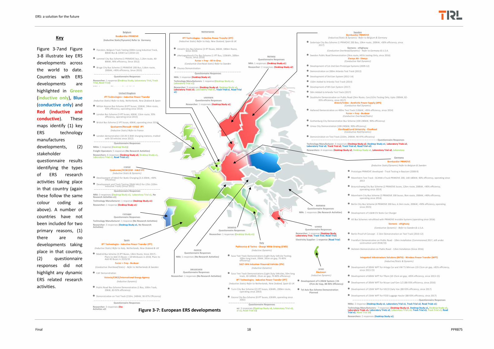
Figure 3-7and Figure
3-8 illustrate key ERS
developments across
the world to date.
Countries with ERS
developments are
highlighted in Green
(inductive only), Blue
(conductive only) and
Red (inductive and
conductive). These
maps identify (1) key
ERS technology
manufactures
developments, (2)
stakeholder
questionnaire results
identifying the types
of ERS research
activities taking place
in that country (again
these follow the same
colour coding as
above). A number of
countries have not
been included for two
primary reasons, (1)
there are no
developments taking
place in that country,
(2) questionnaire
responses did not
highlight any dynamic
ERS related research
activities.
Figure 3-7: European ERS developments

ERS: a solution for the future
Final 19 PPR875
United States of America
Siemens - eHighway
(Conductive Overhead Dynamic) Refer to Sweden & Germany
California Demonstration on Industrial Port Estate - 1.6km Installation, 80-85% Efficiency (Since 2016)
Oak Ridge National Laboratory - Wireless Power Transfer (WPT) (Inductive Static/Dynamic)
7kW Prototype Developed, Laboratory Demonstration (2010)
Development of Power Electronics, Roadside Equipment, V2I Communications (2010-14)
WPT Integration with 2.5kW Toyota Prius, Scion IQ-EV 6.9kW, Chevrolet Bolt 7kW (16-17cm Air Gap, 88-95% Efficiency) (2014-15)
Development of 14-20kW WPT for Toyota RAV4 SUV (16cm Air Gap, 85-95% Efficiency) (2016)
Witricity Corp (Inductive/Static)
Development of WiT-3300 (0.3-3kW, 90% Efficiency, 18cm Air Gap, Since 2014)
Development of DRIVE 11 (3.6-11kW, 94% Efficiency, upto 25cm Air Gap, Since 2017)
WAVE Inc - Wireless Advanced Vehicle Electrification (WAVE) - (Inductive/Static)
Utah State University Bus Scheme Demonstration (1 Bus, 2.5km Route, 50kW, 17.5cm Air Gap, 90% Efficiency, Since 2013)
Monterey, California Bus Scheme Demonstration (1 Bus, 7.5km Route, 50kW, 17.5cm Air Gap, 90% Efficiency, Since 2014)
Japan
Honda R&D CO.
(Conductive Rail Dynamic)
Development of 180-450kW System
—————————————————————–———————Questionnaire Responses
Technology Manufacturer: 2 responses (Desktop Study x1, Desktop Study x1, Laboratory Trial x1, Laboratory Trial x1, Track Trial x1, Track Trial x1, Road Trial x1)
NRA: 1 response (Desktop Study x1, Laboratory Trial x1)
South Korea
Dongwon Inc/K.A.I.S.T. - Online Electric Vehicle (OLEV)
(Inductive Dynamic)
Seoul City Grand Park Trolley (3 OLEV Trolleys, 2.2km Route, since 2010)
Daejeon City Bus Scheme (2 OLEV Buses, 3.76km Route, Since 2013)
Gumi City Bus Scheme (8 OLEV Buses, 35km Route, Since 2014)
Sejong City Bus Scheme (2 OLEV Buses, 24km Route, Since 2015)
OLEV SUV/Car (22kW, 17cm air gap, 71-90%% efficiency)
OLEV Bus 1st-6th Gen (60-100kW, 17-25cm air gap, 72-85% efficiency)
——————————————————————————Questionnaire Responses
New Zealand
IPT Technology - Inductive Power Transfer
(Inductive Dynamic) Refer to Italy, Netherlands, Spain, UK
IPT Demonstration Trial (1 EV Shuttle, Since 1998)
Taiwan
Questionnaire Responses
Researcher: 1 response (Desktop Study x1, Laboratory Trial x1)
Malaysia
Questionnaire Responses
Researcher: 1 response (Desktop Study x1)
India
Questionnaire Responses
Researcher: 3 response (Desktop Study x1, Desktop Study x1, Laboratory Trial x2, Laboratory Trialx1, Track Trial x1, Road
Trial x1)
Pakistan
Questionnaire Responses
Researcher: 3 response (Desktop Study x1, Laboratory Trial x1)
China
Questionnaire Responses
Researcher: 1 response (Desktop Study x1)
Antelope Valley, California Bus Scheme Demonstration (2 Buses, 50kW, 17.5cm Air Gap, 90% Efficiency, Since 2015)
Long Beach, California Bus Scheme (10 Buses, 50kW, 14km Route, 17.5cm Air Gap, 90% Efficiency, Since 2016)
City of McAllen, Texas Bus Scheme (2 Buses, 17.5cm Air Gap, 90% Efficiency, Since 2016)
Development of 250kW System
Stanford University/TomKatCener - Robust Wireless Power Transfer (InductiveDynamic)
Development of prototype system ( 60cm Air Gap, 94% Efficiency, Since 2017)
Plugless Power
(Inductive/Static)
Development of 7.2kW Charger for Tesla Model S & BMW i3 (90% Efficiency, 10cm Air Gap)
Development of 3.3-7.2kW Charger for Nissan Leaf & Gen 1 Volt (90% Efficiency, 10cm Air Gap)
Momentum Dynamics Corp
(Inductive Static, Dynamic under testing)
Development of dynamic and static systems
Americas Asia and Oceania
Figure 3-8: Rest of world ERS developments

ERS: a solution for the future
Final 20 PPR875
3.2 Stakeholder Perspectives
This sub-section provides an overview of stakeholder views regarding ERS implementation, reflecting on online survey results and stakeholder interviews. Full results can be found in the PIARC report here.
3.2.1 Stakeholder activities in ERS
Survey participants were asked what types of ERS activities they had undertaken or plan to undertake. Responses included desktop studies, laboratory testing, track testing and road trials. Results indicate both branches (conductive and inductive) are receiving similar levels of attention. The most common type of activity was desktop studies for both systems. Laboratory testing was the most common activity for inductive systems; however track testing was the most popular activity for conductive systems. This could be due to scale, where inductive systems are much smaller and require less testing space; however, conductive systems require more testing infrastructure. 40 organisations had taken part in ERS road trials, 24 of which were for conductive systems. An interactive map of individual (anonymised) responses can be found here. A snapshot is provided in Figure 3-9.
Similar to the above mapping exercise, Figure 3-10 provides a concise overview of ERS research by type of activity. Individual responses were reviewed to ensure these figures only account for activities related to dynamic ERS.
Figure 3-9: Mapped ERS research activities per online survey responses

ERS: a solution for the future
Final 21 PPR875
UK participants included: 4 researchers, 1 NRA, 5 freight operators, and 1 other. Research activities taking place in the UK are limited, with mixed perceptions of ERS feasibility. Three researchers had been involved in desktop studies for both inductive and conductive ERS, with 1 researcher stating they had participated in road trials for conductive systems and laboratory testing for inductive systems, developing performance evaluation test methods. No one from Freight Industry had undertaken any ERS research activities. The NRA (Highways England) had undertaken work developing a feasibility study regarding the implementation of dynamic inductive systems on the UK strategic network. This study is widely cited in the literature and focuses on the costs and benefits or inductive ERS for the UK situation. Participants were asked if their Organisation planned to undertake any ERS related activities over the next 24 months, however in line with previous responses, further activities are limited. Some participants stated they were waiting for the conclusions of the European FABRIC project (Feasibility Analysis and Development of on-Road Charging Solutions for Future Electric Vehicles) before undertaking or planning future activities. As a point of comparison a vast range of research and development activities are being undertaken in Sweden, Germany, USA, Japan, and South Korea; undertaking extensive track testing and road trials (further details of these activities can be found in the full PIARC report here).
3.2.2 Stakeholder perceptions of ERS impacts on transport system
Participants were asked to rate the effect of ERS on five impact categories if they were to be implemented. A 5 point scale was used from significant benefit to significant impact. An overview of results is presented in
Figure 3-10: ERS research activities per online survey results

ERS: a solution for the future
Final 22 PPR875
Figure 3-11. Generally responses were positive, with many believing ERS could deliver a number of benefits. However, most importantly, many believed that the capital and operational costs of ERS are a significant drawback to implementing this technology. With regards to UK responses, a similar trend is seen:
9 of 11 participants believed ERS could result in minimal to significant benefits for GHG, local air quality, and noise emissions;
8 of 11 participants believed ERS would cause adverse to significant negative impacts regarding capital and operational costs; with many stating the high costs of infrastructure were an issue given other challenges, such as maintaining the quality of the existing network (correcting defects, traffic congestion, etc);
6 of 11 participants believed that vehicle capital and running costs would cause an adverse impact on the current transport system. Many stated that the cost of retrofitting ERS compatible equipment and the price of associated maintenance would increase vehicle costs.

ERS: a solution for the future
Final 23 PPR875
Figure 3-11 Overall perceived ERS benefits/impacts
The environmental benefits of ERS are often publicised as a key selling point for these types of technologies; with Sweden and Germany seriously considering these types of solutions to rapidly decarbonise their road networks in order to meet GHG reduction targets. However it should be considered that noticeable environmental benefits can only be accrued if (1) electricity is produced renewably (if electricity is produced from fossil fuels then GHG emissions will simply be moved from the roadside to the power plant, however there would be an improvements in local air quality as there are zero emissions locally), and (2) if there is sufficient uptake of EVs and ERS compatible EVs (especially from freight industry). Generally NRAs and Researchers in the UK were more optimistic about ERS developments and implementation. However, there were mixed responses from Freight stakeholders, with the majority believing that ERS was an untenable solution. Specifically freight stakeholder
believed that their industry could:

ERS: a solution for the future
Final 24 PPR875
(1) Not bear any further costs for new equipment or be responsible for a share of infrastructure capital costs;
(2) Already had difficulties operating under current network conditions (congestion along high volume routes, excessive road roadworks);
(3) Would be unable to update their vehicle fleets due to recent upgrades and investments
in cleaner vehicles;
(4) Organisations were not large enough (in terms of fleet size) to be able to use this technology efficiently;
(5) have doubts over the grid capacity and connections at the roadside would be met to
allow for this technology to be implemented;
(6) Fleets are cheaper to operate using fossil fuels once other ERS costs are taken into account
However UK freight stakeholders all recognised the potential benefits ERS could deliver in terms of environmental parameters. Stakeholders were asked to elaborate on their answers and discuss the main benefits ERS could realise. These are summarised for all systems in Figure 3-12. From an NRA perspective these include:
Conductive overhead:
The most mature solution (trials in Sweden and Germany on public roads);
Can provide higher levels of power suitable for HGVs;
Rail/tram industry stakeholders have years of experience installing, operating and maintain similar systems;
Does not impact the pavement structure;
For the most part they can be installed at the roadside leading to minimal disruptions;
Does not affect routine pavement maintenance activities.
Conductive rail:
Can transfer higher levels of power;
Suitable for all types of vehicles;
A lot of transferable knowledge from rail/tram industry;
Can be easily inspected as most components are visible and accessible.
Inductive solutions:
Does not impose on established winter maintenance activities;
Safer in terms of road user or worker interaction;
No visual impact as they are buried;
ERS: a solution for the future
Final 25 PPR875
Suitable for a number of vehicle types; less vulnerable to damage or vandalism.
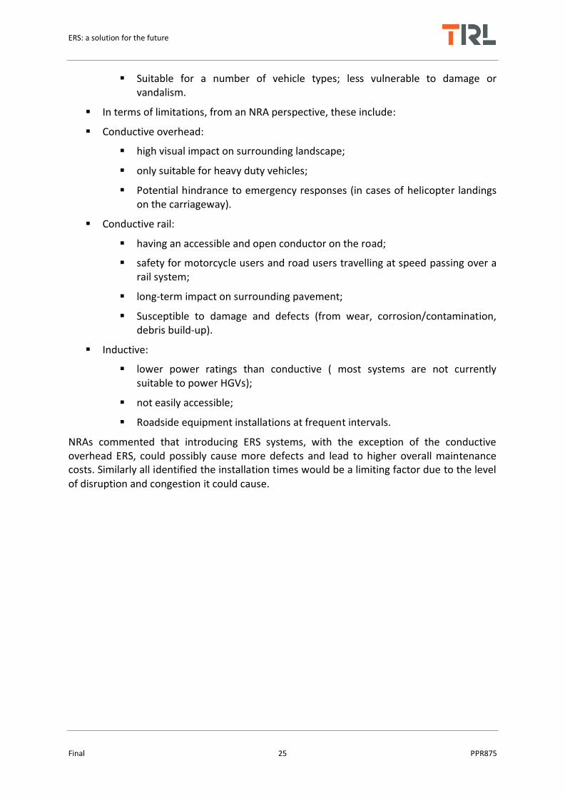
In terms of limitations, from an NRA perspective, these include:
Conductive overhead:
high visual impact on surrounding landscape;
only suitable for heavy duty vehicles;
Potential hindrance to emergency responses (in cases of helicopter landings on the carriageway).
Conductive rail:
having an accessible and open conductor on the road;
safety for motorcycle users and road users travelling at speed passing over a rail system;
long-term impact on surrounding pavement;
Susceptible to damage and defects (from wear, corrosion/contamination, debris build-up).
Inductive:
lower power ratings than conductive ( most systems are not currently suitable to power HGVs);
not easily accessible;
Roadside equipment installations at frequent intervals.
NRAs commented that introducing ERS systems, with the exception of the conductive overhead ERS, could possibly cause more defects and lead to higher overall maintenance costs. Similarly all identified the installation times would be a limiting factor due to the level of disruption and congestion it could cause.
ERS: a solution for the future
Final 26 PPR875
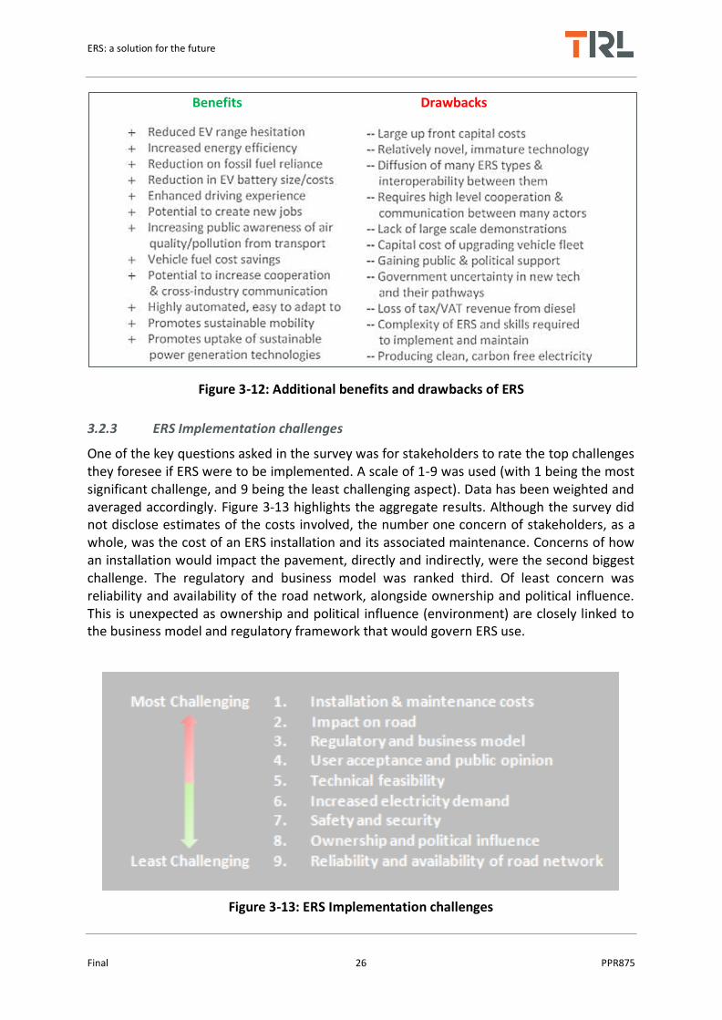
Figure 3-12: Additional benefits and drawbacks of ERS
3.2.3 ERS Implementation challenges
One of the key questions asked in the survey was for stakeholders to rate the top challenges they foresee if ERS were to be implemented. A scale of 1-9 was used (with 1 being the most significant challenge, and 9 being the least challenging aspect). Data has been weighted and averaged accordingly. Figure 3-13 highlights the aggregate results. Although the survey did not disclose estimates of the costs involved, the number one concern of stakeholders, as a whole, was the cost of an ERS installation and its associated maintenance. Concerns of how an installation would impact the pavement, directly and indirectly, were the second biggest challenge. The regulatory and business model was ranked third. Of least concern was reliability and availability of the road network, alongside ownership and political influence. This is unexpected as ownership and political influence (environment) are closely linked to the business model and regulatory framework that would govern ERS use.
Figure 3-13: ERS Implementation challenges
Benefits Drawbacks

ERS: a solution for the future
Final 27 PPR875
Figure 3-14 illustrates the above results by stakeholder group. This highlights the different concerns and priorities organisations have across the ERS industry. These challenges are not unique to any one type of ERS concept, they are all equally applicable. Stakeholder views were explored in more depth through interviews of representatives of the different depths.
Figure 3-14: ERS challenges by stakeholder group
During interviews stakeholders were asked what their main concerns/considerations were for implementing ERS in their respective countries. The concerns of road administrations were wide ranging, with some concerns being country specific. However most stated that the biggest issues/primary considerations they had regarding ERS relate to:

ERS: a solution for the future
Final 28 PPR875
Technological feasibility – are current systems capable of delivering high levels of power suitable for HGV use; how reliable current systems are (not only their power transfer capabilities but also communications and energy payment protocols)
Road user satisfaction/safety – what level of disruption will installing and maintaining these system have; which type of road users will they be suitable for; how available will the systems be; what level of coverage is required; and what are the risks for road users (regarding electrocution, vulnerable road users and so on)
Funding and investment strategies – finance, ownership and maintenance of the systems, what is the payback time, what the level of uptake will be; will there be private sector investment or alternative financing.
Installation and maintenance – what impact will routine winter maintenance have on systems; how will the presence of systems alter existing maintenance strategies;
Procurement and Supply – Is industry capable of supplying the materials in the quantities that would be required for large scale installations; is industry able to produce enough ERS compatible vehicles within a short time frame to encourage uptake.
During interviews stakeholders were asked what their opinion of current ERS developments and solutions were. Most NRAs interviewed believed that ERS concepts were promising and were seen as a positive potential step towards improving low carbon road transport. Others indicated a limited understanding of ERS, given its relative novelty, and were not in a position to definitively state a position.
Whilst many were open to both conductive and inductive solutions, some administrations had a preference. For instance, one interviewee commented that a conductive overhead or rail solution would not be suitable due to safety concerns (regarding motorcycle users and electrocution in general), visual impact, and their impact on routine winter maintenance activities. Other administrations commented that future ERS uptake will include both inductive and conductive solutions. LMIC participants viewed the technologies as promising however any potential ERS uptake would be secondary to other issues such as health care, basic infrastructure, education etc. LMICs had concerns regarding the cost and security of
ERS due to vulnerability to theft, vandalism and political instability.
NRAs also noted that concessions on their highways ranged between 5-16 years. Given the capital costs involved, coupled with initially low uptake of EVs and ERS compatible vehicles, some NRAs believed that longer concessions would need to be granted for in order for contractors to recoup their original investment. Some estimated that concessions would need to run for 25-30 years instead of the current standard. All European NRAs stated that they would, if not already, be happy to provide test sites (both off-road and on-road) for future demonstrations, alongside supporting further research and development activities. Regarding installation times NRAs all commented that systems should ideally take no longer
than current resurfacing works take; this would be in the range of 4-8 day per km.
All NRAs interviewed stated that currently there is little to no demand for this type of infrastructure. As discussed this is a result of a number of factors. For instance all ERS technologies are fairly novel and still under development, as such there are many

ERS: a solution for the future
Final 29 PPR875
stakeholders (especially freight and industry) who are not yet as informed as there is little national/international discussions taking place. Some commented that ERS discussions begin with national governments clearly setting out their position with regards to ERS. Many felt that if Governments provided clear directives or roadmaps towards implementation, this would enable freight operators or early adopters to uptake this technology. This highlights the “chicken and egg” situation were road users will not adopt if supporting infrastructure is not available and if there is low uptake of EVs or ERS compatible vehicles there will not be sufficient demand to match investment. All acknowledge that the uptake of EV’s have been very low given the upfront capital costs and range limitations.
Interviewees had mixed responses regarding the question “what will an ERS future look like and how will rival (including non-ERS technologies) work together”. Some manufacturers felt that in the context of long distance travel (i.e. freight corridors across multiple countries in Europe) there could only be one type of solution, as interoperability between vehicles and countries is essential (and having many types of solution all working together would be extremely complicated to implement). On the other hand, some manufacturers felt that all solutions would have to work together to decarbonisation transport, especially in the context of achieving GHG targets within Government set timeframes. Further to this many stated that in line with key challenges, discussed above, the goal for any ERS manufacturer was for their systems to encourage greater EV uptake (which requires involvement from all solutions). In this light, ERS would be a backbone solution covering only strategic locations of any road network, with rival technologies (fuel cells, battery swap etc) filling in the spaces
in between.
While there were mixed views as to whether a single network should host multiple ERS solutions there was a clear consensus that some solutions were more suitable for certain purposes and geographies. For instance in urban centres where there are many grid connection points and elevated concerns over public safety an inductive solution might be more suitable. In closed environments (such as ports, industrial estates, mines) where heavier loads are moved along short set routes, with less chance of human interaction, a conductive solution is more appropriate. Similarly for mountainous or hilly terrain a conductive solution may be better placed as they are capable of delivering higher rates of
power than current inductive solutions.
In general, NRAs interviewed had not yet identified a clear winner to back. In some cases this was due to a lack of knowledge on ERS, and in others it stems from the recognition that climate change target deadline are fast approaching and they would need to utilise every resource they have at their disposal to meet them. When considering the possibility that rival technologies (i.e. improvements in battery performance, size, weight, cost and charging convenience/time) could render ERS redundant many, across all stakeholder groups were unsure what impact this could have for an ERS future. Many noted that at the current rate of development (i.e. for batteries, alternative fuels, etc) sufficient advances would not occur soon enough (or in the case of alternative and bio fuels production would not meet the demand of the transport industry alongside competing industries) to achieve current GHG reduction targets in a cost effective way.

ERS: a solution for the future
Final 30 PPR875
3.2.4 Technology Readiness Level and Time to Deployment
Given background and experience, stakeholders were asked to provide estimates of the technology readiness level (TRL) for each concept as a whole, regardless of manufacturer. Additionally stakeholders were also asked to estimate the time to deployment (in years). Figure 3 17 provides an overview of technology readiness levels.
Figure 3-15: Technology Readiness Level (TRL) description
Figure 3-16and Figure 3-17 provide the averages of stakeholder estimates for TRL and years to deployment (YTD). It can be seen that on average, stakeholders believed that conductive overhead static charging and inductive static charging were the most mature concepts with average TRL’s of 7 (2.3 YTD) and 7 (2.2 YTD) respectively. With regards to dynamic applications inductive and conductive in-road ERS were at a similar level of development, with TRL ratings of 5 (5.5 YTD) and 5 (5.5 YTD). On average, stakeholders believed that the most advanced ERS concept, in terms of development, was the conductive overhead solution, with a TRL rating of 6 (4.1 YTD). This estimate reflects the fact that the conductive overhead solution has a long standing history as it is essentially an evolution of overhead rail

ERS: a solution for the future
Final 31 PPR875
and trolley bus technologies, which have been in use for many decades. In light of recent developments, overhead conductive systems are subject to larger and longer
demonstrations than alternative ERS concepts for highway use.
Figure 3-16: Estimated TRL/YTD by stakeholder group
ERS technology TRL Level Years to Deployment
Inductive (Static) 7 2 Inductive (Dynamic) 5 6
Conductive (Dynamic Overhead) 6 4 Conductive (Dynamic In-road) 5 6 Conductive (Static Overhead) 7 2
Conductive (Static In-Road) 6 4
Figure 3-17: Average estimated TRL/YTD
3.3 Task 1 Summary
Overall ERS concepts are viewed positively by all stakeholder groups; with the general understanding that ERS are capable of providing significant environmental and economic benefits (in terms of GHG emissions, local air quality, noise, and road user fuel costs). However a majority felt that installation and operation costs were a significant disadvantage of ERS. Large number of research projects (public and private) and majority of participants’ organisations plan to continue ERS development activities. Freight Operators were the most pessimistic about the financial viability of moving to ERS, believing infrastructural and vehicle running costs to be a disadvantage. In general the biggest challenge for stakeholders

ERS: a solution for the future
Final 32 PPR875
are the installation and maintenance costs, the impact on existing infrastructure and the regulatory/business model surrounding their deployment. Technical feasibility, safety and security, ERS ownership and political climate were also seen as primary challenges by all stakeholders.
Benefits of ERS, as perceived by stakeholders, include: reduced EV range anxiety; increased energy efficiency of transport; less reliance on fossil fuels; reduction in EV battery costs (reducing the overall price of an EV); fuel savings; promotes uptake of sustainable power generation technologies; potential to increase cooperation and cross industry communication; increasing public awareness of air quality/pollution from transport; potential to create jobs and economic opportunities. Disadvantages of ERS, as perceived by stakeholders, include: large upfront capital costs for infrastructure; immature technologies as applied to transport; diffusion and interoperability of ERS systems; the number of actors involved requiring high level cooperation and communication; lack of large scale demonstrations; capital cost of ERS compatible vehicles; gaining public and political support; government uncertainty in new technologies and their pathways; loss of revenue from fossil fuel sales; availability of skilled workforce to implement and maintain infrastructure; difficulties producing low carbon electricity; and lack of funding and government support for ERS. Average estimates for TRL’s and YTD are: dynamic inductive = TRL5 with 6 YTD; dynamic conductive rail = TRL5 with 6 YTD; and dynamic conductive overhead = TRL6 with 4 YTD.
Interviews were carried out with 13 participants: 6 NRAs, 5 Technology Manufacturers/Consultants, 1 Research Institute, 1 Freight Vehicle Manufacturer. NRAs were unsure of inductive ERS suitability for HGVs, especially with regards to system reliability in power transfer, communications, and payment methods. NRAs stated that current ERS installation times (although these are for demonstration purposes) would cause unacceptable levels of disruption to their networks during construction, alongside the impact ERS will have on maintenance strategies. Any installation would have to be installed at a similar rate to existing works, optimally occurring at the same time as resurfacing/reconstruction works. NRAs were concerned about procurement and supply of materials, especially in the context of fair competition as there are limited ERS technology manufacturers. NRAs had different preferences of which type of system was more suitable for their network (depending on their safety/environmental requirements) – no general favourite system but acknowledged that conductive overhead systems were the most mature and nearest to market.
NRAs believed ERS would be best suited on toll roads, but would have to extend concessions to allow for satisfactory payback. All commented that having available grid capacity and connections along the highway would require significant investment. In this context ERS is more suited to urban environments where these are more readily available. All interviewed stakeholders believed at present there was little to no demand for ERS, but that a main driver behind ERS developments was national commitments to reducing GHGs. Most stakeholders agreed that Freight and Public Transit organisations would be the first adopters of ERS. Interviewed stakeholders stated that Governments needed to provide clear statement of intent to invest in ERS and develop roadmaps for their implementation. Only then could demand increase. Many believed there was not a rivalry between different ERS solutions or competing technologies. The type of ERS implemented will depend on the

ERS: a solution for the future
Final 33 PPR875
application/environment it is intended to be used in. Rival low carbon technologies were typically seen are complementary to ERS, and in the context of climate change targets Governments would have to employ every solution at their disposal.

ERS: a solution for the future
Final 34 PPR875
4 Task 2: Comparison of different ERS technologies
This section provides an evaluation of the ERS technologies identified in Task 1, discussing both conductive and inductive systems. A qualitative assessment of the risks associated with each ERS is also presented.
4.1 Technological feasibility
4.1.1 Technical feasibility of inductive ERS
Task 1 gathered information on a number of ERS technologies being currently developed and trialled. A total of 17 systems were identified, 11 of which were classed as inductive ERS and these systems are highlighted in Table 4-1. In this section, the technical feasibility of these inductive systems is discussed in terms of potential advantages and disadvantages.
Table 4-1: Dynamic inductive ERS overview
System Organisation Power & Efficiency Vehicle Suitability
TRL
OLEV Dongwon Inc. / KAIST
15-85kW, 71-91%3, 4,
5,11,14,15 Buses, LVs, LDVs Tram/Rail
9
CWD Politecnico di Torino / CRF
20kW, 75-85%5,114 LVs, LDVs 3-4
IPV Seat Emmedi Group
20kW, 70-80%5,27 LVs, LDVs, HGVs Buses & Shuttles
3-4
PRIMOVE Bombardier / Scania Up to 200kW, 68.8-90%5,32,45
LVs, LDVs, Buses
5-6
HALO Qualcomm
20kW, 80%5 LVs, LDVs 3-4
WPT Oak Ridge National Laboratories / OEM’s
2.5-20kW, 88-95%5,48,49,51
LVs 3-4
INTIS Integrated Infrastructure Solutions
11-60kW, 88-93%107,108,110
Small Plant, LVs
3-4
Electreon Electreon Inc. 5-20kW, 88-90%166 LVs& Buses 5-6
Victoria CIRCE Up to 50kW, 92%167 Buses & Shuttles
7-8
WPT University of California
Up to 200kW, 60%5 LVs, LDVs, HGVs
2-3

ERS: a solution for the future
Final 35 PPR875
Momentum Charger
Momentum Dynamics Corp.
50-75kW (upto 300kW), 95%121
Buses and Shuttles
3-4
Full descriptions and discussions of each system can be found in the full PIARC report here.
There are a number of technological barriers that need to be overcome for dynamic inductive charging to become feasible. The following issues have been identified as the most immediate issues for inductive ERS manufacturers:
A number of systems (CWD and IPV) have issues synchronising primary coil segments with the vehicle pick-up. Synchronisation is affected by vehicle speed, lateral alignment, signal switching and communications speeds; all of which can impact the power transfer rate and overall efficiency.
A number of inductive systems have low power ratings, typically around 20kW, which are only suitable to light duty vehicles. For powering larger vehicles, power levels, efficiencies and misalignments need to be improved. This is especially relevant given the findings of [149] which conclude the only feasible near term applications of ERS are for metropolitan bus schemes, and freight corridors (short-long-international haul).
At current levels of development inductive systems are only capable of delivering power at vehicle speeds of approximately 80-100km/h, which is ideal for trucks which have a maximum highway speed of 90km/h in most states. However this is not suitable for passenger vehicles which would typically travel much faster (up to 120-130km/h).
Another important issue that needs addressing is the ability of multiple vehicles to charge on a single segment or coil section. This factor is related to the synchronisation of coils and their communication speeds.
One of the main challenges is interoperability, which is the ability of different ERS systems to power electric vehicles regardless of vehicle type. Currently, interoperability does not exist in ERS systems (inductive or conductive) in terms of providing efficient power transfer, from the grid to the ERS, and for multiple vehicle types. In addition, there are no standards or regulations available to provide a clear path for interoperability to occur. IEC 61980177 aims to provide standardisation for inductive power transfer for EVs, but guidelines do not exist yet or are still in development.
For ERS interoperability to become functional, it requires communication protocols. In terms of existing standards, the ISO/IEC 15118198 (“Road vehicles -- Vehicle to grid communication interface”) standard governs the charging of electric vehicles (ISO/IEC15118198, DIS, 2011), dealing specifically with the communication links between vehicles and charging equipment. This standard could be used as a starting point for ERS interoperability.
Other factors that limit efficiencies and power levels between systems include:
IPR;
installation depths (similar air gap);
ERS geometry (coil size, dimensions);
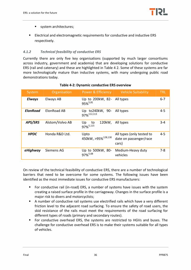
ERS: a solution for the future
Final 36 PPR875
system architectures;
Electrical and electromagnetic requirements for conductive and inductive ERS
respectively.
4.1.2 Technical feasibility of conductive ERS
Currently there are only five key organisations (supported by much larger consortiums across industry, government and academia) that are developing solutions for conductive ERS (rail and catenary) and these are highlighted in Table 4 2. Some of these systems are far more technologically mature than inductive systems, with many undergoing public road demonstrations today.
Table 4-2: Dynamic conductive ERS overview
System Organisation Power & Efficiency Vehicle Suitability TRL
Elways Elways AB Up to 200kW, 82-95%5,81
All types 6-7
ElonRoad ElonRoad AB Up to240kW, 90-97%112,113
All types 4-5
APS/SRS Alstom/Volvo AB Up to 120kW, 97%5,115
All types 3-4
HPDC Honda R&D Ltd. Upto 450kW, >95%128,130
All types (only tested to date on passenger/race cars)
4-5
eHighway Siemens AG Up to 500kW, 80-97%5,68
Medium-Heavy duty vehicles
7-8
On review of the technical feasibility of conductive ERS, there are a number of technological barriers that need to be overcome for some systems. The following issues have been identified as the most immediate issues for conductive ERS manufacturers:
For conductive rail (in-road) ERS, a number of systems have issues with the system creating a raised surface profile in the carriageway. Changes in the surface profile is a major risk to divers and motorcyclists;
A number of conductive rail systems use electrified rails which have a very different friction level to the adjacent road surfacing. To ensure the safety of road users, the skid resistance of the rails must meet the requirements of the road surfacing for different types of roads (primary and secondary routes).
For conductive overhead ERS, the systems are restricted to HGVs and buses. The challenge for conductive overhead ERS is to make their systems suitable for all types of vehicles.

ERS: a solution for the future
Final 37 PPR875
Conductive overhead systems are also limited to open roads and motorways; tunnels, bridges and roads with any overhead infrastructure would not be suitable for these systems;
The Honda system is limited to roads with VRS; therefore roads with no VRS, and any roads with hard shoulders or emergency stop lanes (all motorways) would not be deemed suitable for this system.
4.2 Impact on infrastructure and maintenance
Road pavements are designed and constructed to carry a certain volume of traffic over a given design period, which is typically >40 years for major highways with remedial surfacing treatments expected every 10-15 years. The responsibility of maintaining the pavement condition to a high level of safety and comfort is overseen by the highways authority or road administration, with design and maintenance procedures carried out under specifications set forth by the administration. Whilst on-road ERS currently exist, to date, installations in public roads are rare with no data available on the effects on pavement condition from these sites. As installation procedures are expected to be ERS specific, special dispensation would be required to allow ERS installations on any given road network, based on evidence provided from laboratory testing and off-road trials. Furthermore, the extent of the potential impact on the maintenance and operation of the road network will be largely unknown, except for conductive catenary ERS which should have no impact on road condition and expected maintenance operations. Therefore, in this section we are only considering the impact of inductive and conductive rail ERS on infrastructure and maintenance.
Roads and highways with inductive and conductive rail ERS will be expected to have similar service lives to conventional pavements for NRAs to consider integrating this technology on their road networks. Although maintenance intervals may be more frequent initially, the presence of the ERS in the carriageway should not take away from the long-term performance of the road and therefore induce no increase to maintenance costs. The key areas associated with ERS that will impact on road infrastructure and could to lead to additional road maintenance are highlighted below:
ERS installation method; Materials used in the installation; Performance monitoring and maintenance operations of the ERS and pavement.
For full discussions of the above factors the reader is advised to refer to the full PIARC report found here.
4.3 Safety and security
The greatest concern to road owners is safety. Concerns over road worker and user safety, particularly during maintenance operations, and skid resistance are likely to rank highly in future implementation plans. To help understand the safety and security issues associated with ERS, this section discusses some of the major risks identified in this study.

ERS: a solution for the future
Final 38 PPR875
4.3.1 Skid resistance
One factor that is highly correlated with accident risk on roads is skid resistance. Whilst the skid resistance requirements may vary with country, the effects of ERS implementation may be similar. It is generally accepted that the installation of materials with lower skid resistance properties than the adjacent road surfacing should be avoided. Where conductive rail ERS is introduced into a pavement, the change in the skid resistance is even greater due to the reduced friction of the metallic rails. If the skid resistance of the rails and the road surface is significantly different, there is a risk that vehicles will tend to slew under braking. In order to minimise this risk, the skid resistance of the rails should ideally be similar to that of the road surface.
4.3.2 Road surface profile
For inductive and conductive rail ERS, the main safety concern is the height of the ERS above the road surface. An uneven road surface can lead to driver safety concerns and uncomfortable driving experience for road users especially at high traffic speeds. Designated lanes which have ERS equipment installed on the road surface between the wheel paths may be a viable solution but there are still major concerns over safety for road users especially motorcyclists, the effects on changing lanes, and the potential impact on vehicles that breakdown (e.g. tyre blowouts on HGVs).
4.3.3 Road maintenance and resurfacing
In terms of future road maintenance and resurfacing operations, there is no information available in the public domain where this has been fully addressed. When the road surfacing has reached the end of its service life, which can vary between 8-15 years depending on the effects of traffic, weather etc., it will need to be resurfaced. For ERS installed along the centre of the road, it may be possible to plane off the asphalt surfacing on either side of the system, depending on the location and depth of transverse power cables. However, assuming that it is safe to undertake such maintenance, the potential effects of this operation on the performance of ERS is unknown. The development of a bespoke road planning equipment for roads equipped with ERS may be required although comments from key stakeholders suggest that this may not be necessary. There is a need to identify and outline safe operating procedures for future maintenance and resurfacing operations
4.3.4 Access and cybersecurity
Access chambers may be required for underground roadside equipment. It is likely that these access chambers will be located on the roadside verge or footpath. If located on a footpath, the covers should be flush and level with the surrounding surface, so as to not present a trip hazard to pedestrians. Although sub-surface roadside equipment may be a safer option in regards to road users than above-surface roadside equipment, health and safety regulations for working in enclosed spaces would have to be strictly adhered to. The equipment should not be easily accessible by members of the public e.g. any housing covering the roadside equipment should be securely closed, to prevent accidental or deliberate contact with potentially large electric currents. Most if not all inductive system

ERS: a solution for the future
Final 39 PPR875
will require a wireless connection between the vehicle and the charging infrastructure. This is required to inform the charging system that a vehicle needing power is approaching, and that the vehicle in question has the right to draw the power (e.g. an account exists for the user). Furthermore, various systems require a negotiation to establish the required and safe power levels available for power transfer. Typically this communications link needs to be high-speed and low latency, so is normally implemented using Wifi or some similar system.
In addition, the infrastructure equipment will require a communications link to a back-office control system for system status, updates and logging. This will normally use standard Internet protocols. In both cases, the communications system will require protection against cyber-attack. As existing systems have moved little beyond prototype stages, little information is available on cybersecurity measure implemented. The cybersecurity requirements for conductive systems are expected to be similar to those for inductive systems, though the latency requirements for the vehicle to infrastructure communications are unlikely to be as onerous, and could probably be achieved using mobile phone technology.
4.4 Regulatory framework and standards
The regulatory framework for road transport consists of legislative instruments (acts of parliament, EU Directives, government licences, regulations, rules), international and national standards, the regulatory bodies which set and enforce these and regulatory processes. The regulations relevant to ERS relate not just to transport, but also to consumer rights, procurement and competition, energy provision, health and safety, environmental protection and land-use. Regulations may be enforced through the courts e.g. through penalties for organisations or individuals. Compliance of road administrations with regulations may also be overseen by the appropriate government ministry or a separate government body. For example Highways England operates through a licence agreement which is monitored by the Office of Rail and Road (Infrastructure Act 2015 174). Energy regulators e.g. OFGEM, would also play a role.
Introducing a disruptive technology such as ERS to road networks will inevitably raise a number of regulatory challenges. Public procurement rules exist to promote fair competition. If a technology is only produced by one manufacturer these regulations may present a problem, as it will effectively create a monopoly. This also relates to intellectual property rights (IPR)/patents and interoperability; as it depends on whether similar technologies can be produced and integrated on the same network. If there is a monopoly, economic regulation would be required to ensure customers are treated fairly. This could be integrated into the role of existing transport regulators or require a new organisation to be established.
The delivery mechanisms of ERS is still being debated, but might well include some form of PPP where the technology is installed on a public road network, but owned and maintained by a private company. This raises a number of potential issues:
In some countries e.g. Sweden there are regulations about the installation of equipment on public roads which is not owned by a public organisation.

ERS: a solution for the future
Final 40 PPR875
If there are no domestic suppliers of ERS, then any laws that restrict foreign investment in national infrastructure may cause difficulties.
If there is an accident involving the ERS system, there may be uncertainty as to who would be liable for damages.
It is also unknown who is responsible for securely processing the personal data which needs to be collected for payment, and data sharing between the various organisations involved would be carried out securely.
The legal rights of a road administration in regard to land ownership can be complicated. In the UK road administrations do not necessary own the land itself (i.e. the sub-soil and the air space above it), but uphold the right of the public to travel over the land without obstruction with specified powers and duties related to this set out in the Highways Act 1980. Unless purchased by the road administration for construction the land belongs to the original landowner (most likely the owner of the adjacent land). It is unclear as to how the installation and operation of ERS relates to this legal position as it is outside the normal duties and powers of a road administration to provide safe travel and maintain the road infrastructure.
All the ERS technologies require the installation of electrical equipment (and VRS) adjacent to the road and the overhead systems also require the installation of gantries. Assuming that this land is available, road administrations would not necessarily own the land, so would require access. In the UK road administrations have the power to carry out specific tasks requiring access such as construct and maintain drains, protect the highway against natural hazards or install barriers. Other types of equipment are not mentioned, so may not be covered. Obtaining access could require purchasing land or providing landowners with compensation, it may even involve compulsory purchase.
The energy industry is highly regulated. Independent regulators are responsible for the regulation of the energy sector including safety, ensuring demand is met, protecting consumers in regard to quality and pricing, and promoting competition. Usually a licence or permit is required to carry out activities such as electricity generation, transmission, distribution and supply. These licences include certain conditions or standards, and in the EU the relationships between the different licence holders are strictly governed. For example, it is not possible to both distribute and supply electricity so if the road administration or PPP organisation that operates the ERS own the transformer and grid connections it may be the case that it cannot then sell electricity to vehicle owners. Exemptions for internal grids are possible, but there may be limits on voltage, extent and ownership by a private company. The procurement of electricity in the EC is open to competition; if only one electricity supplier provides the charging service this could require amendment to current laws.
The regulatory framework for ERS is complex and bespoke to individual countries, and even individual regions within countries. It is likely to require several years to put in place or amend relevant legislation. For example the Autonomous and Electric Vehicles Act 2018 175 provides new powers for the government to ensure motorway service stations have sufficient electric charging points and to address insurance concerns in relation to autonomous vehicles. The new laws include:
ERS: a solution for the future
Final 41 PPR875
Making sure that public charge points are compatible with all vehicles;
Standardising for the payment schemes;
Introduction of standards for reliability and quality assurance.
It could be envisaged that a similar act would be required for ERS.
The physical characteristics (size, weight, materials, strength, and robustness) of ERS will be a key consideration for road administrations. For systems to be installed on, beneath or above the road they will have to meet existing regulatory standards, or require standards to be adapted to allow for the implementation of these novel technologies. For example regarding the physical size of components buried under the road (such as inductive coils, casings, and cabling) the Specification for the Reinstatement of Openings in Highways176 (SROH) section 1.8.1 mandates that equipment with an external diameter greater than 20mm is not permissible unless special circumstances exist144. The standard states that the size of the system shall not weaken the structural strength of the pavement or its wearing course. The only size limitation for overhead conductive systems would relate to its clearance from the ground. In this case it must comply with standards for bridges and tunnels, allowing safe passage of extra-large vehicles. Additionally this clearance should also comply with electrical safety standard. For instance in the UK the minimum clearance of overhead electric cables, in a publicly accessible area, is 5.2m.
There are a number of requirements any type of system must comply with regarding consequences under operation. The pavements mechanical characteristics can be impacted by changes in strength, skid resistance, waterproofing, and surface profile consequently leading to accelerated deterioration and potential safety issues. Under operation, a system should not exceed the ambient temperature of the pavement, remaining below 40°C. Beyond electromagnetic compatibility (EMC), no specific requirements have been identified regarding EMF emissions from buried or roadside equipment. However, EMF emissions should not interfere with existing equipment (variable message signs, optical and magnetic sensors, traffic lights, ITS transceivers). Furthermore EMF should not interfere with communications equipment used by emergency services, road workers, or health devices (such as pacemakers) for drivers/passengers/pedestrians. Legislation only exists for EMF regarding public or worker safety; there are currently no regulations that cover EMF emissions within a pavement structure.
The IEC Technical Committee 69 (IEC-TC69) is responsible for the standardisation of EVs including charging infrastructure. Requirements for off-board equipment (such as power electronics and switching boxes) are specified in IEC 61980: Electric Vehicle Wireless Power Transfer Systems177. This standard governs: the characteristics and operating conditions of the off-board supply equipment; specifies the off-board electrical safety requirements; communications (for safety and system processes); requirements for equipment positioning (for efficiency and processes); requirements for multiple vehicles using a system and specific EMC requirements (those not covered in IEC 61851-21-2178). However the standard does not relate to safety aspects related to periodical maintenance; off-road conductive systems (trolley buses, rail vehicles); and power circuit supply (covered in ISO 6469179). Overhead requirements for catenary based solutions for electric vehicles likely to use current rail standards.
ERS: a solution for the future
Final 42 PPR875
SAE J2954168 Wireless Charging of Electric and Plug-in Hybrid Vehicle outline the guidelines for inductive power transfer for light duty Plug-in and electric vehicles and alignment methodology. The practice covers electromagnetic compatibility, EMF, minimum performance, safety and testing. There are a number of general requirements:
Hazardous live parts shall not be accessible. Use IEC TS 60479-1 2005 Effects of current on human beings and livestock180.
Protection measures against electric shock under single faults conditions shall be implemented (BS EN 61149).
IEC 60364181 is an international standard for installations for buildings (BS7671182 in the UK or NFPA 70183 in the US). The standards cover protection for safety, selection and installation of equipment, requirements for special installations including electric vehicles and verification.
Accessible parts of the WPT system from exceeding certain temperatures to prevent skin burns when touched accidentally or intentionally IEC Guide 117184 and IEC 60364-4-42:210-05. The metal parts with bare metallic surface should not exceed 80 °C. and the parts with non-metallic surface should not exceed 90 °C
Degrees of protection against access to hazardous parts: The minimum IP degrees in public road installation: IP 69K (ISO20653185) as installed.
Human exposure to electromagnetic waves is one of the standout points for the inductive power transfer, governed by the Institute of Electrical and Electronic Engineers (IEEE) and the International Commission on Non-Ionizing Radiation Protection (ICNIRP). Reviews by both organisations have found there is no evidence that radio frequency EMF cause cancer, however they may increase body temperature, stimulating nerves and muscle tissue. The main standards related to ERS are as follows:
Guidelines for Limiting Exposure to Time-Varying Electric and Magnetic Fields (1 Hz - 100 kHz). Health Physics 99(6):818-836; 2010186.
IEEE Standard for Safety Levels with Respect to Human Exposure to Radio Frequency Electromagnetic Fields, 3 kHz to 300 GHz”, IEEE Std. C95.1-2005187.
IEC62311: Assessment of electronic and electrical equipment related to human exposure restriction for electromagnetic fields (0Hz to 300 GHz)188.
IEC62233: Measurement methods for electromagnetic fields of household appliances and similar apparatus with regard to human exposure189.
1999/519/EC, "Council Recommendation of 12th July 1999 on the limitation of exposure of the general public to electromagnetic fields (0hz to 300Ghz), Official Journal if the European Communities No. L 199, 30th July 1999, pp. 59–70190.
In summary, there are standards, regulations and guidelines that road operator should consider for conductive and inductive power transfer solutions. The main concern for wireless power transfer is the impact of electromagnetic exposure on humans due to inductive power transfer through the air gap. The ICNIRP or IEEE standards provide similar guidelines to comply with EM exposure. The main concern for conductive solutions, especially for rail systems is the exposure of live wires/rails, the IEC standard states that

ERS: a solution for the future
Final 43 PPR875
hazardous live parts should not be accessible, this means that the solutions should only active when there is an compliant vehicle using it and there is no possibility for a human to be in contact with rails/wires during power transfer. In terms of conductive overhead cables, the cable should be out of reach of humans with sufficient clearance; the rail industry standards can be adopted and modified where necessary for vehicles on road.
4.5 Risk Assessment
A risk evaluation in terms of operational and maintenance safety was carried out. The risk assessment considers the full lifecycle of the technologies and includes the risks to all affected parties. The aim is to understand the safety risks resulting from each technology and whether these can feasibly be managed: high level mitigations are considered. Three different types of system were considered:
Inductive power transfer (Dynamic)
Conduction charging (Overhead equipment)
Conduction charging (In-road-rail)
The outcomes of the risk assessment are summarised in Figure 4-1. Examples of each risk can be seen in Figure 4-2. Definitions of each risk category are given below:
Very Low/Low: risks are likely to be acceptable and require controls to be in place. There is a high level of confidence that risks can be reduced to a tolerable level with reasonably practicable mitigations.
Medium: Likely to be tolerable but will require careful management to ensure risks are as low as reasonably practicable.
High/Very High: Level of risk could be intolerable. Further design work, investigation or testing likely to be required to provide evidence that the level of risk is tolerable.
Inductive ERS risks (no of risks identified per lifecycle stage)

ERS: a solution for the future
Final 44 PPR875
Conductive rail ERS risks (no. of risks identified per lifecycle stage)
Conductive overhead ERS risks (no. of risks identified per lifecycle stage)
Figure 4-1: Risk assessment results for inductive, conductive rail and conductive overhead ERS (no. of risks identified per life cycle stage

ERS: a solution for the future
Final 45 PPR875
Figure 4-2: Example ERS risks from each risk category

ERS: a solution for the future
Final 46 PPR875
4.5.1 Inductive ERS risk summary
In total, 29 hazards were identified for this type of technology. It can be seen that the majority of hazards identified in this risk assessment fall into the very low or low category, with three hazards being determined to fall within the medium region. Risks of medium concern include the increased exposure for operatives to live traffic when maintaining the system and carrying out repairs. There were no hazards identified as being in the high to very high region. The presence of this technology overall fits within the very low to low level of concern but there are areas that should be looked at further. For example, having inductive ERS equipment near roads and live traffic, over a lifetime may increase the exposure period an operative experiences having to work next to live traffic. This could increase if the systems that are laid underground are found to be inefficient and impacted by severe weather (ice, snow, and flood) which precipitates further maintenance work. Further research and testing would need to occur to investigate this.
4.5.2 Conductive Rail ERS risks summary
In total, 48 hazards were identified for conductive rail ERS. The most of all the technologies considered. It can be seen that although the majority of hazards identified in this risk assessment fall into the low category, there are key risks that have been categorised as presenting high or very high level of concern. Key risks include debris and the requirement to remove debris to ensure the safe operation of the system and the embedded rail either causing electrocution or destabilising motorcyclists. Hazards deemed to have high risk levels should undergo further testing and investigation to provide evidence that the level of risk is tolerable or identify appropriate mitigations to reduce the risk to a tolerable level.
4.5.3 Conductive Overhead ERS risk summary
In total, 34 hazards were identified for this system. It can be seen that the majority of hazards identified in this risk assessment fall into the low category but some hazards are within the medium category, which may require further investigation and mitigation. One unique risk is an emergency helicopter being unable to land due to presence of overhead equipment. Although this technology has been in use for over a century in the rail industry, it is important to understand that the control of overhead line equipment within the railway occurs in a controlled environment where infrastructure is not widely accessible to the general public. Should this ERS be deployed within the public domain, the ability to control the movement of vehicles and driver competencies is reduced.

ERS: a solution for the future
Final 47 PPR875
5 Task 3: Business models and cost-benefit analysis from a road administrations perspective
In this section potential business models for ERS are considered from a road administration perspective. This includes a discussion on the costs associated ERS including the capital costs involved in installing the system and also its on-going operation and maintenance costs. The development of a coherent business model in conjunction with demonstrations of the whole systems including charging technology is needed in order to commercialise ERS. A business model requires identification of the value proposition, customers, revenue source and how it will be obtained, expenses and the actors involved in delivery.
5.1 Understanding the market and competition
For all ERS concepts it is expected that the main customers will be freight operators using HGVs, although the in-road systems could also be used by LVs on longer journeys providing them with a larger customer base than overhead systems. Passenger cars are likely to charge at home if possible, as this is likely to be cheaper and more convenient than public charging facilities. However, on longer journey drivers may choose to top-up on route in which case ERS could be used and some drivers may not have the off-street parking required for installation of charging equipment so would need to use public charging facilities. Intercity buses and coaches could also use ERS if static charging at depots and stops are not sufficient for longer journeys. Static charging facilities are therefore a significant competitor technology for LVs, but are currently less relevant to HGVs.
For LVs to take advantage of ERS, they would need to have the appropriate equipment installed, which would add weight and additional cost to vehicles. This may mean that although it technically feasible for them to use ERS it is not practical or economic when there are alternative static systems. Also the majority of LVs are used mainly for short journeys, whereas HGVs travel long distances. Understanding the potential market for ERS is important as a system designed solely for HGVs may look very different to a system aimed a more mixed user group both technically and in terms of the business model. User behaviour, convenience and cost (initial and operating) will all play a role in determining the potential market and if this will include both freight operators and private cars.
Some stakeholders have suggested that freight operators may only require 25km per day of charging to achieve satisfactory payback compared to diesel operations. Research from [9] suggests that for a KAIST/Dongwon bus, operating along a specific route, would consume €12.5k/year of electricity, equivalent to €50 per km of route per year. Estimates from [114] suggest that for passenger cars travelling 65km per day would cost €325/year; resulting in a saving of €1500/year compared to equivalent journeys using diesel. Estimates from [63] suggest an annual saving of €15k-18k per bus using an ERS system. [65] Estimate that commercial freight operators can save 57-82% of their diesel fuel costs using ERS. [68] Indicate that commercial freight operators can save €20k per 40-tonne truck travelling 100,000km on fuel expenses using overhead conductive ERS. [78] States that 1km of conductive rail ERS can provide €157k of fuel savings per year (when all user savings are aggregated). Furthermore [78] concludes that 20,000km of conductive rail ERS could provide €3.1bn annual savings compared to diesel use.

ERS: a solution for the future
Final 48 PPR875
A further consideration is the potential for disruptive technologies around connected and autonomous vehicles, mobility as a service (MaaS) and the sharing economy to radically alter the current business model of privately owned vehicles. Future scenarios could see people pay for mobility as required, which could for example be based on public transport and shared pods in cities, and specific vehicles for longer journeys. A potential future where private vehicle ownership is drastically reduced in favour of shared EVs could drastically reduce the vehicles in urban environments in place of highly utilised electric vehicles that might require some form of dynamic charging.
Another aspect which could determine the market for a particular ERS system is interoperability. Currently a variety of technologies have been developed and demonstrated with no interoperability between or within concept types. The various conductive solutions proposed are all inherently non-interoperable, and some (e.g. the Siemens E-road) are limited to limited classes of vehicles. The interoperability considerations for inductive power transfer systems are more advanced. It is recognised that installing multiple non-interoperable systems is not viable, and efforts have been started in standards bodies to standardise the key parameters which will affect interoperability. For example ISO 19363 standardises the magnetic field requirements for inductive power transfer, while ISO 15118 addresses the communications interfaces between the vehicle and the infrastructure.
5.2 Revenue sources
Revenue is expected to be generated by charging a fee to customers who choose to charge their vehicles using the technology, most likely this will be through an on-board charging system which calculates the cost based on the amount of electricity consumed.
A yearly fee or EV vehicle only toll road (e.g. to a port or mine) are also possibilities. The options for fleets and private individuals might be different, and there could be different prices and / or taxes on this basis. Other options for private customers could be to have a private EV allowance as part of a MaaS contract. Different charges could also be applied during peak times or busy routes in order to moderate demand.
In order to be financially viable the electricity mark-up and uptake of the technology need to be sufficient to fund the operation and maintenance of the system and payback the initial investment over a reasonable timeframe. It should be noted that the private sector normally expects a higher rate of return on transport infrastructure investments than the public sector e.g. up to 20% to 30%. Another point to consider is the loss of government revenue from fuel tax as VAT on electricity is currently less than diesel in most countries. Whereas the mark-up needs to be high enough to make the ERS economically viable, it also needs to be low enough that users of the system have reduced costs compared to conventional fuels. This includes recouping their investment in vehicle equipment within a reasonable time period. Electric vehicles are more efficient than diesel and electricity is less expensive, so this should be possible. Governments may also wish to subsidise the cost at least initially to encourage take-up.

ERS: a solution for the future
Final 49 PPR875
5.3 Actors and drivers
The commercial delivery of ERS involves complex interactions between several actors, all of which need to benefit from the enterprise. Although reductions in carbon and air pollution are important government policies, these external costs are unlikely to drive customer and investor behaviour to the extent economic costs do. For example:
The customer benefits by obtaining an affordable, convenient, reliable source of power with minimal cost to upgrade their vehicle and little maintenance.
The government meets its low carbon policy objectives and supports national industry.
The road administration has a new revenue stream (or at least no additional costs) and meets customer needs and government requirements.
The electricity supplier sells more electricity and experiences a more balanced electricity demand.
When considering costs, it should be noted that it is not proposed to install ERS on the entire network. For instance, interviews with NRAs (who are heavily involved in ERS developments) have suggested that by electrifying only 5% of their road network they could achieve approximately a 50% GHG reduction (compared to current levels). This is also seen in the KAIST/Dongwon installations where only a small proportion of the buses route is electrified.
5.4 Types of Business Model
Key questions to be answered in developing the business model are:
Who funds the installation of the equipment?
Who funds the operation and maintenance of the system?
How much will users pay to use the system?
How much are vehicle owners willing to pay to install and maintain the equipment?
Who receives payment by the users?
How long will it take to repay the initial investment?
Like EVs there is a chicken and egg situation, with hauliers only likely to purchase ERS equipment for their fleet if there are sufficient routes to use it and funders only willing to invest in installing the technology if there are sufficient vehicles with the equipment installed for them to recoup their investment within a reasonable time period. In order to ERS to be introduced it is likely that government support is required for funding/part funding the initial investment and through policies and financial incentives to promote up-take. For example 70% of the costs of the Swedish e-highway trial are publically funded.
It is possible that ERS could be fully funded by the government; i.e. they would fund installation, operation and maintenance; and charge users to recoup the public investment. However, most business models currently being discussed for ERS generally envisage some type of private-public partnership between the government and private stakeholders. The

ERS: a solution for the future
Final 50 PPR875
exact form this would take and the actors involved depends on the system type, e.g. if it is suitable for both LVs and HGVs or the route particular benefits a particular industry or region. This could be some form of concession, similar to a DBFO road or structure which transfers the risk of poor uptake to the private sector. It is also affected by the size of the required capital investment, appetite for risk by the government and private sector and strength of the carbon reduction policies and drivers from government. The business model also needs to align with the regulatory framework which may need some modification to accommodate private ownership and investment in public roads.
5.5 Cost-benefit analysis
A CBA model was developed to provide some insight into the likely costs and benefits of ERS over its lifetime and the payback time on the investment made. As the model was developed for the UK the costs are in GBP and the inputs to the model were set to reflect a case study motorway within the UK, with electricity prices, traffic levels, speed limits etc. all based on UK data. The UK Department for Transport guidance on transport appraisal WebTAG151 approach to cost-benefit analysis was followed as a guide. The model outputs and assumptions are:
Results in terms of a 1km ERS installation;
The assessment period is 20 years;
Estimates of annual operational costs (for maintenance, administration, electricity costs);
Estimates of annual benefits accrued from selling electricity to users;
Estimates of annual societal benefits (expressed in both absolute and monetary terms) for reductions in CO2, NO2, PM;
Cumulative balance and payback time.
5.5.1 CBA scenarios
The CBA ran across several scenarios which included:
Electricity mark-up and emission factors
Constant for entire appraisal period
10-65% mark-ups were assessed (values represent range between minimal mark-up to cover running costs, on top of industrial tariffs, that would make the road user price comparable to domestic tariff used while charging at home).
All emissions factors and unit prices are UK specific
All electricity prices based on 2017 UK average/kWh
ERS vehicle up-take (for rail and inductive only)
Annual take-up rate for both LVs and HGVs: 5%
Initial percentage of equipped LVs and HGVs: 5%

ERS: a solution for the future
Final 51 PPR875
Limit to the technology penetration in the LVs fleet: 30%
Limit to the technology penetration in the HGVs fleet: 75%
The maximum penetrations achieved were chosen to reflect the likelihood that a much lower proportion of light vehicles would need regular on-route re-charging, given typical trip distances and battery ranges, than is the case for heavy vehicles. The same HGVs percentages have been used for the overhead system (while the model uses 0% for all the parameters in the case of LVs, since the technology is for HGVs only). It is assumed that both HGVs and LVs can use rail and inductive ERS as there are there are systems able to accommodate both vehicle types being tested, even if these are developed to different rates.
Infrastructure costs and emissions (for material, labour, grid connections, equipment, and commissioning)
Cost ranges explored for entire installation for inductive systems between £445k-£4.4M/km
Cost ranges explored for entire installation for conductive overhead systems between £1.96M-£2.31M/km
Cost ranges explored for entire installation for conductive rail systems between £400k-£1.34M/km
A 3.5% NPV discount rate has been used
All emissions factors and unit prices are UK specific
Different ERS have different efficiencies. These have been summarised from the available literature and incorporated into the analysis to determine electricity requirements for road users, given in Table 5-1.
Table 5-1: ERS efficiencies used in CBA
System Efficiency
range
Average
efficiency
LV consumption at
68mph constant
speed (kWh/km)
HGV consumption at
56 mph constant
speed (kWh/km)
Inductive 60% -- 91% 73% 0.22 1.95
Overhead 80% -- 97% 87% 0.18 1.66
Rail 82% -- 97% 87% 0.18 1.66
Based on efficiency and technology penetration assumptions for LVs and HGVs fleet the energy demands have been calculated; these are illustrated in

ERS: a solution for the future
Final 52 PPR875
5.6 CBA results summary
With a mark-up of 10% on the electricity price none of the scenarios analysed reaches the break-even year by the 20 years of the assessment. An inductive system whose cost is around £4.3 million (€4.9 million), does not reach the break-even year in a 20 years period with an electricity mark-up of 65%. An inductive system which costs as much as the OLEV system, Imin, has a similar outcome to the cheapest rail system Rmin in terms of paid back year, which is the sixth year of operation. They both reach high savings after 20 years; the inductive system in particular allows larger savings (about £1 million higher than the cheapest rail system, Rmin). A rail system on the high side of the cost range can reach the break-even year before 20 years for high mark-ups on the electricity. The highest mark-up considered (65%) needs 13 years of operations before starting receiving a profit, which can be as high as £2.7 million after 20 years of operations. The overhead system analysed does not reach the break-even year in 20 years in any of the scenarios analysed. Results of different electricity mark-ups are summarised in Table 5-2 and Table 5-3.
Table 5-2: Break-even year and balance after 20 years
Mark-up 10% Mark-up 65%
System Break-even year Savings after 20 years
Break-even year Savings after 20 years
Inductivemin >20 years - 9.0 M£ >20 years -2.9 M£
Inductivemax >20 years -0.4 M£ 6 5.7 M£
Overheadmin >20 years -4.0 M£ >20 years -0.2 M£
Overheadmax >20 years -4.7 M£ >20 years -1.0 M£
Railmin >20 years -0.4 M£ 6 4.7 M£
Railmax >20 years -2.5 M£ 13 2.7 M£
Figure 5-1 UK energy profiles per km per year for ERS

ERS: a solution for the future
Final 53 PPR875
Table 5-3: NPV divided by capital cost for two electricity mark-up scenarios
PR1 NPV/k
System type Mark-up 10% Mark-up 65%
Inductivemin -0.59 7.87
Inductivemax -1.29 -0.42
Overheadmin -1.26 -0.06
Overheadmax -1.28 -0.26
Railmin -0.64 7.36
Railmax -1.15 1.25
The following three figures (Figure 5-2, Figure 5-3, and Figure 5-4) show the annual costs, broken-down in to administrative, maintenance and electricity costs. The first chart on each figure is a reminder of the capital cost, which is a one-off cost in the first year. Note that the y-axis is different between the capital cost charts and the annual costs. The maintenance cost has been assumed to be 1% of the capital cost, therefore this figures are different in the six scenarios reported in the figures44, 45, 82, 150. The electricity cost depends on the system efficiency (for a given technology take-up rate); therefore, this cost for the rail system is equal to the electricity cost for the overhead system (which is due to the electric HGVs only), plus the electricity cost due to the electric LVs. The administration cost has been set to be 5% of the total electricity cost (as an indicator of the number of users); therefore, it is the same value for a same system type (that is, regardless of the capital cost).
Figure 5-2: Annual costs (administrative, maintenance and electricity) for Conductive overhead ERS

ERS: a solution for the future
Final 54 PPR875
The balance sensitivity to capital cost and electricity mark-up is provided in Figure 5 8. Note that the overhead charging systems is used by HGVs only, which reduces the amount of user payments.
Figure 5-3: Annual costs (administrative, maintenance and electricity) for Inductive ERS
Figure 5-4: Annual costs (administrative, maintenance and electricity) for Conductive rail ERS

ERS: a solution for the future
Final 55 PPR875
Figure 5-5: Variation of the cumulative balance after 20 years (NPV in market units of account) with capital cost of the system and electricity mark-up
CO2 emissions are calculated from the difference between reductions caused by a shift in fleet composition (from ICE to electricity), and the increase in emissions from power production to fulfil additional demand from EVs. CO2 savings, for a given up-take scenario, are the same for HGV fleets using conductive systems due to equal efficiencies. However, the overall CO2 values differ between conductive systems as rail systems can be utilised by both HGVs and LVs (therefore for rail total emissions savings are higher). Tailpipe NOx and PM emissions factor in ICE vehicle reductions; therefore emissions reductions due to HGVs shifting to electricity is equal for all three ERS solutions for a given technology penetration rate. Overhead systems result in lower emissions savings as they are not compatible with LVs. Table 5-4 provides an overview of emissions savings over the 20 year appraisal period.
Table 5-4: Emissions savings over 20 years
System type Total CO2 savings per
km
Total NOx savings per
km
Total PM savings per
km
Tonnes saved
Damage saving
Tonnes saved
Damage saving
Tonnes saved
Damage saving
Inductive 39.5k £3.8M 49
£49k*
£1M ** 3
£160k*
£380k*** Rail 42.1k £3.9M
Overhead 25k £2.4M 8.7
£8.5k*
£170k** 0.7
£40k*
£90k**
* **
***
damage cost, central value
abatement cost, central value inner conurbation

ERS: a solution for the future
Final 56 PPR875
Figure 5-6 illustrates annual CO2 savings forecasted for ICE, LV, and HGV fleets.
Figure 5-6: Annual CO2 emissions forecast for the ICE fleet, CO2 savings achieved using inductive and conductive rail (for LVs and HGVs) and conductive overhead systems (for
HGVs only)
Figure 5-7 provides an illustration of the key findings from the CBA and emissions savings assessments.

ERS: a solution for the future
Final 57 PPR875
Figure 5-7: CBA and emissions savings summary (blue = conductive rail, green = inductive, turquoise = conductive overhead

ERS: a solution for the future
58
5.7 Task 3 Conclusions
ERS economic feasibility is dependent on electricity prices, discount rates, traffic levels, EV up-take, technology penetration, and capital/maintenance/administration costs. Based on the scenarios calculated the following conclusions are drawn.
Overhead systems are the cheapest to install with inductive systems being possible the most expensive solution;
The largest proportion of cost arise from purchasing electricity (maintenance and administration costs are much lower). Overhead scenarios resulted in the lowest operational costs, with inductive ERS having the highest (a factor of power transfer efficiency);
GHG savings rely on ERS efficiency and technology penetration. Rail ERS resulted in the greatest GHG reduction (a factor of high overall efficiency and suitability for all vehicle types). Conductive overhead resulted in the lowest GHG saving (as it can only be used by HGVs);
NOx and PM reductions are a factor of changing fleets (assumed to be the same for ICEs switching to inductive and rail ERS). Again these savings are lowest for conductive overhead as it is only suitable for HGVs;
Over a 20 year period no ERS recoups its capital investment with a 10% electricity mark-up;
At 65% electricity mark-up both conductive rail and inductive (at lowest capital estimates, at higher capital cost brackets inductive do not result in a saving) resulted in significant savings. Overhead markets are affected by limited vehicle suitability (HGVs only) so did not result in a direct economic saving.
Conductive rail ERS was the only technology to achieve savings under all but 10% electricity mark-up scenarios, achieving payback between 6-13 years (depending on cost bracket).
In conclusion, under the assumptions of the analysis it is clear that ERS has the potential to return positive gains (in terms of economic and environmental savings) depending on electricity mark-up. However, it is unknown how the willingness to pay for ERS users would compare to current solutions (fossil fuels cost or charging at home cost). It is likely that LVs will charge at home as this is cheaper than paying the ERS tariff or commercial rate at service stations. Users however, may be willing to pay for the convenience ERS affords. In terms of vehicle operating costs, at 65% electricity mark-up, fuel costs for HGVs are still cheaper than diesel, incentivising freight operators to adopt the technology and move away from fossil fuel consumption. Regarding which system an NRA should invest in, the capital cost of overhead systems (plus confidence in the technology readiness) is lower than other systems; however there is a longer payback time. As such, although conductive rail and inductive ERS are more expensive in the short term, they result in a faster payback and higher savings as they can be utilised by LVs and HGVs.
From discussions in the literature it seems the most likely business model is some form of public-private partnership. The most advanced thinking in this area comes from Sweden and

ERS: a solution for the future
59
suggests that the capital cost and investment risk is too high for most private organisations to be the sole investors, and that Government (national and/or regional) funding is required. Government is likely to accept longer payback times than private investors, and are more likely to invest in technologies that result in emissions savings.

ERS: a solution for the future
60
6 Study conclusions
This study was funded by the TRL Academy in parallel to the World Roads Association PIARC study Electric Roads – A Solution for the Future. The main tasks included:
1. To describe ERS with regard to their its Technology Readiness Level (TRL) and the key players involved in its development
2. To compare different ERS technologies and their perceived advantages and disadvantages
3. To consider the business model from a Road Administration perspective
The project identified 16 different ERS technologies currently in development, 11 of which were classed as inductive, and 5 classed as conductive (rail and overhead combined). Information was collected on each system on parameters such as: power output and efficiency, operational speed, suitability for different vehicle types and evidence of performance levels (laboratory testing, off-road trials, on-road trials). Based on the information collected the technology readiness level (TRL) was assessed.
6.1 Technological feasibility
An assessment of technology readiness and market readiness was carried out and showed a wide range varying from TRL 2-9. The majority of the inductive ERS systems (50%) scored between TRL 3 and 4, whilst only two systems had a TRL greater than 6. The majority of the conductive ERS systems (60%) scored between TRL 4 and 5, whilst the remaining two systems had a TRL between 6 and 8. The KAIST/Dongwon OLEV (from South Korea) and the SIEMENS (from Sweden) systems appear to be the most advanced inductive and conductive ERS technology respectively and those closest to market readiness. The majority of the remaining ERS technologies are still at demonstrator stage and require or are in the process of undertaking on-road trials to determine their technical feasibility.
Power outputs were generally greater for conductive ERS which showed greater capability for charging HGVs, whilst inductive ERS appears to be more suited to powering lighter vehicles and buses, with the exception of the Bombardier system which is currently conducting testing with HGVs. The majority of the conductive ERS systems were capable of achieving efficiencies greater than 90%, whilst the inductive ERS efficiency levels had greater variation between 70-95%. The main challenge for inductive ERS functionality is to improve power transfer efficiency and maintaining it for different vehicle types. Currently, interoperability is practically non-existent for all ERS systems.
6.2 Stakeholder perspectives
NRAs and ERS manufacturers believed that the first adopters would be freight industry and public transit operators. The biggest challenges stakeholders foresaw regarding ERS implementation is the high capital costs of all types of ERS and the legal/regulatory framework and business model that governs their deployment. Stakeholders felt that the main disadvantages of ERS aside from the high capital costs of equipment included the risk associated with relatively immature technologies (with limited public demonstrations illustrating viability), lack of interoperability between vehicle types and across systems, and

ERS: a solution for the future
61
the uncertainty of the impact that installations may have on the long-term performance of road infrastructure. Another important limiting factor is the development of a clear strategy or statement of intent from governments on whether or not they consider ERS as a viable solution. Without clear guidance and support, ERS manufacturers and early adopters assume higher levels of risk in adapting this technology.
6.3 Advantages, disadvantages and challenges
The risk assessment presented in this report provides an indication of the safety and associated levels of concern of each system. Of the ERS technologies reviewed (including static charging and plug-in charging solutions), the plug-in charging systems were identified as the system to present the lowest level of risk, largely due to the fact the risks are well known and understood. Of the three ERS technologies, the inductive and conductive overhead ERS presented similar levels of risk (very low-medium), with the conductive rail ERS showing higher levels of risk overall. Risk assessments should be conducted for individual technologies and designs to ensure all risks are reduced as low as reasonably practicable through appropriate design and mitigation. Once risks are considered to be tolerable, the system should be tested and trialled both off and on road to validate identified risks and tolerability of risk decisions
Future maintenance of roads containing ERS is highly dependent on the type of construction required for each system and the design life of the in-road components of the ERS. Conductive overhead ERS should have no impact on road condition and expected maintenance operations. For conductive rail and inductive ERS, collaborative studies between technology manufacturers and NRAs should demonstrate if the ERS is durable enough to withstand the conditions experienced on heavily trafficked motorways and will require limited maintenance during its service life. The expected ERS maintenance varies depending on system type; ERS technologies reviewed in this report indicate that for some types maintenance may be required every 10-30 years while others are expected to be maintenance free over their lifetime. Due to the novelty of these installations it would be remiss to expect that these sites will meet the original design life of the pavement or remain defect free for these durations.
In this study, static charging solutions and electric battery technology are seen to be complimentary to ERS development and implementation. Advancements in these areas should see an increased uptake of EVs which reduces concerns for road users and promotes the use of EVs, thereby increasing support for dynamic ERS solutions where circumstances allow. Uptake of EVs using these battery solutions may only be suitable for light vehicles and commercial buses rather than HGVs due to battery size and charging time constraints. However, the greater power transfer efficiencies associated with conductive static charging solutions may reduce the potential implementation of ERS particularly for buses and light vehicles. Biofuels are only an intermediate step in decarbonisation as they are not zero carbon. The lack of refuelling infrastructure also means biofuels and alternative fuel options such as hydrogen fuel cells may struggle to generate growth in their respective areas.
Results from the CBA showed that emission savings (CO2, NO2 and PM) were similar for conductive rail and inductive ERS as these systems were analysed for both light vehicles and

ERS: a solution for the future
62
HGVs. Only HGVs were included in the analysis for conductive overhead systems, so the reductions were not as great.
Vehicle emissions in the model were calculated using UK-specific emission factors. These are lower for new vehicles. Equivalent emission factors vary significantly with the age and composition of vehicle fleet, as well as other factors such as maintenance and driving style.
6.4 Economic feasibility and business models
The CBA shows that some types of ERS are financially viable if sufficient capital investment can be made, as long as the electricity mark-up and uptake is sufficient. Systems able to accommodate LVs as well as HGVs are more likely to recoup the initial investment, even if uptake in LVs is much lower than HGVs. There is a need to better understand the market for ERS, in particular if LVs will use the system and the role of alternative technologies and other future social and technological changes. Further work is also required to better understand which types of routes different ERS technologies would be suitable for. The most likely business model is a PPP which will probably require modifications to the regulatory framework.
6.5 Summary statement
This study has drawn on literature, stakeholder views, cost-benefit analysis and expert opinion in order to review ERS and its potential. There are still many unknowns with regard to these systems, but based on the information currently available the response to the question the study set out to answer “Is ERS a potential solution for the future?” – is in the long term, yes. This study has shown that all three ERS concepts are technically feasible and potentially financially viable and therefore could contribute to decarbonising transport systems. However, in the short term, wide spread implementation of ERS is not likely as there are still many unknowns with regard to its implementation. There are specific safety and maintenance concerns which still need to be addressed, uncertainty around policy and regulations and the business model is not fully developed. ERS may be a viable solution in the shorter term, in certain locations where circumstances prove financially viable i.e. there is likely to be a high uptake such as along bus routes in urban areas or along freight routes between ports and distribution areas.
It is unlikely ERS will be universally rolled-out across road networks, but if the identified issues are resolved over the next 5 – 10 years early adopter NRAs could start to install ERS on certain routes with high HGV use.
For further discussion related to all aspects of this report, readers are highly encouraged to review the full PIARC study (and its detailed appendices) – Electric Roads a Solution for the Future.
ERS: a solution for the future
63
7 Recommendations
This section provides a series of recommendations based on the project findings. This is divided into recommendations for road administrations and researchers.
7.1 UK road administrations
Some road administrations will be early adopters, while others will prefer to take a 'wait and see' approach, gaining a better understanding of the potential risks and opportunities from the experiences of other road administrations. It is currently unknown which approach the UK will take, and if there will be differences across the country.
It is to be expected that road administrations will select the recommendations they feel is most appropriate for them. In order to aid this, the recommendations are divided into suggested:
• First steps – early actions to understand ERS and its feasibility.
• Interim steps – to become ready for ERS.
• Advanced steps – for road administrations who want to be early adopters.
It is to be expected that most road administrations will focus on the early steps over the next 5 years, with a smaller number of early adopters carrying out interim and advanced steps.
7.1.1 First steps
The first step is to better understanding ERS and its potential impact on road network. First steps could include:
Participation and attendance in international conferences on ERS;
Join PIARC, FEHRL and other technical committees discussing ERS;
Learn from leading administrations (i.e. Sweden and Germany);
Prepare updated feasibility studies;
Promote the use of low carbon vehicles.
7.1.2 Intermediate steps
Deployment of ERS will require a long lead-in time. In addition to technical preparations, planning regulations, technical standards and working practices etc. will need to be modified. It is recommended that road administrations that are considering ERS start taking some no-regrets low cost actions in preparation for the deployment. In doing this road administrations should not become fixed-in to one type of technology, as currently there is no front runner type of ERS and it is most likely a combination of technologies including static and ERS will contribute to the de-carbonisation of the road transport system. Instead, it may be better to identify key decision points whilst keeping an open mind on the various ERS options. Example actions are:
Assess the potential impacts of ERS;

ERS: a solution for the future
64
Identify suitable routes for ERS;
Develop guidelines for ERS ;
Identify specifications and standards that will require modification;
Commission further research into all ERS aspects (i.e. safe/quick installation methods, business models, environmental impact assessments, road user impact assessments);
Discuss the possibility of installing ERS with Government and policy levers to encourage uptake;
Create a cross-industry forum;
Assist development of international standard and guidelines (especially with regards to interoperability);
Commission ERS demonstrations (laboratory, track and road trials) to demonstrate commitment to their low carbon vision;
Gain public and political support.
7.1.3 Advanced steps
It is suggested that road administrations which wish to be early adopters of ERS support trials of the most promising technology and work with industry to ensure infrastructure requirements are taken into account. Example actions include:
Participation in trials:
Identify the most suitable ERS candidates for meeting the NRAs needs and objectives;
Validate manufacturers claims and verify ERS safety and functionality;
Validate long-term performance and system tolerances (for the system itself and its impact on existing infrastructure;
Compare installation methods and grid requirements of each system;
Validate cost estimates for installation, maintenance, and grid connections;
Provide road space for ERS demonstrations.
Working with Government (i.e. to ensure the regulatory framework is flexible enough to adopt a new transport technology and business models – Governments need to communicate a strong commitment and message to industry if ERS is to be deployed)
Participate in joint trials (i.e. collaborate with other road administrations, share test facilities and trial vehicles – maximising lessons learnt
Publish results from track/road trials

ERS: a solution for the future
65
7.2 Researchers
Public and private researchers will be at the forefront of ERS developments. While a wealth of information exists regarding ERS there are still many topics that have not received adequate attention, or have transparent publicly available results published. Based on this study, alongside review of current literature the following topics are suggested for areas of future research:
The impact ERS will have on UK grid capacity and requirements, and how demand profiles for ERS will impact grid loading, especially in the context of peak demand;
Undertake long-term or accelerated testing of ERS components to better understand how in-road equipment will impact the durability and performance of the pavement structure;
Carry-out life cycle assessments (LCA) for various ERS solutions to better understand their environmental performance compared to the current transport system and alternative low carbon solutions. A challenge for this is that a truly reflective LCA will need to be conducted in collaboration with ERS manufacturers to fully understand the materials used and their origins, production and installation processes, and transport distances/modes for moving materials. Given ERS novelty, and the stage of development (for a particular solution) designs are likely to change/evolve over the next few years. As such any LCA should include flexible scenarios that accommodate future developments;
Study the infrastructural requirements for mass-scale implementation of ERS to better understand what proportion of the network would need to be electrified in order to achieve substantial carbon reductions whilst being commercially competitive;
Assess the maintenance requirements of ERS and how these could impact routine road maintenance, in terms of cost, efficiency and time;
Research legislative drivers and policy levers in the UK that could encourage ERS and low carbon vehicle up-take;
Undertake social impact assessment to understand the wider societal implications of moving towards low carbon vehicle technologies;
Undertake driver behaviour studies to explore and understand the practical safety implications of ERS implementation;
Understand and incorporate the uncertainty of ERS technologies into any type of analysis;
Conduct detailed assessments of the implications rival or complementary technologies will have on future ERS demand (such as battery improvements);
Freight and public transit operators will be the likely first adopters of ERS. This will help reduce emissions in the near term but greater savings depend on passenger vehicle up-take of EVs/ERS compatible EVs. Research should be undertaken to understand what mechanisms can be utilised to encourage greater passenger vehicle up-take of these technologies, and what future demand pathways will look like;

ERS: a solution for the future
66
Understand how ERS can be incorporated with Intelligent Transport Systems (ITS) to ensure charging via ERS occurs optimally, without impacting traffic flows.
Explore possible scenarios where ERS installations are the optimal solution outside of highways. For instance how suitable are ERS for closed environments such as ports, mines, industrial estates and so on – environments where there is a high degree of control over who enters an ERS system and when; also where routes are fixed, subject to little change, and handle high volumes of traffic across relatively short distances;
Understand how ERS technologies can be applied to other industries, outside of roads to encourage further technological development; for example, using inductive charging for industrial applications and plant (such as warehouse material handling, cranes, factory processes, and so on);
Investigate the challenges and implications for ERS with regards to autonomous vehicles; exploring whether or not these technologies can be integrated with one another to understand if driving and refuelling can be completely automated processes;
Conduct material testing to understand how routine winter maintenance will impact ERS durability and performance; for instance a number of systems cannot be subjected to de-icing using salts, what are alternative methods for de-icing/ploughing that are competitive and efficient compared to salting.
Undertake research to better understand how current ERS implementation costs can be minimised to make them more commercially viable and incentivise demand;
There are many issues regarding inductive ERS that require further attention from developers and researchers including: vehicle speed profiles in relation to misalignment; flow and power management for multiple vehicles using a single ERS segment; interoperability and frequency variations between systems; synchronisation of coils and power transfer; universal communication protocols and networks that are fast, secure, and do not interfere with existing communication equipment.
7.3 Freight Industry
Freight industry is a key near-term market for ERS adoption. However given limited demonstrations, existing infrastructure, commercial ERS products, and clarity over viability from a freight organisation business model perspective; demand will only be driven if freight industry can understand that the costs and benefits of ERS (and low carbon technologies in general) outweigh the business as usual model (fossil fuel operations). Freight industry should maintain an open mind regarding various ERS options and their suitability for their operational needs. Example actions include:
Stay updated with ERS, EV, and low carbon technology developments around the world to better understand if any type of low carbon systems is suitable or profitable for your operations;

ERS: a solution for the future
67
Identify high volume routes, shared with many other freight organisations, to assist governments and road administrations in recognising which sites may be suitable for early ERS demonstrations;
Develop a deeper understanding of how freight movements impact emissions;
Review government incentives, green financing, and subsidies for low carbon technologies and the impact these will have on your business model;
Learn from freight industry in leading low carbon countries (i.e. Sweden);
Communicate with ERS manufacturers to better understand upfront vehicle costs and ERS vehicle component maintenance requirements;
Support the development of low carbon technologies and infrastructure;
Participate in ERS demonstrations where possible;
Understand national GHG reduction legislation and the long-term impact this will have on your business model.
7.4 Government
The UK Government is ultimately responsible for meeting national carbon reduction targets and is in a position to lead and support industrial efforts to achieve these. The recent Freight Carbon Review201 identified the challenges in reducing road freight emissions and reviewed various options for addressing this including ERS. A clear message to industry regarding the Government’s stance on the electrification of roads and the roles of novel technologies for decarbonising the current transport system would help to promote investment. Specific actions government could take include:
Deliver a clear statement regarding their position on ERS technologies, and electrification of road transport in general (e.g. produce a White Paper on the Electrification of Roads);
Provide suitable funding programmes to allow for Public-Private-Partnerships in ERS demonstrations;
Investigate regulatory modifications that would be required for UK adoption of ERS
in terms of legislation.
Explore policy levers for encouraging uptake of carbon reduction technology, especially for freight markets;
Establish lines of communication with leading administrations in ERS (i.e. Sweden and Germany);

ERS: a solution for the future
68
8 Acknowledgements
TRL would like to express their deepest appreciation to all those who provided inputs, time and data for this project. We thank all those that took the time to complete our online questionnaire, participate in workshops and interviews. In particular we thank: Trafikverket, Highways England, Sanef Group, Uganda National Roads Authority, SANRAL, IMT, Scania AB, Siemens AB, Dongwon Inc., Alstom Group, Electreon, BASt, J-N-J Miller Design PLLC, Oxford Policy Exchange, and the UK Department for International Development, M. Lamb Consulting, and all those who provided permissions, data, and shared their experiences of ERS with us. Of special mention we would like to thank the PIARC Project Oversight Team for their efforts, expertise and direction throughout this joint project.

ERS: a solution for the future
69
9 References
1. KAIST (2014) Shaped Magnetic Field in Resonance, media release, Available at:
http://www.smfir.co.kr/_userfiles//BOARD_NOTICE/14320908091.pdf
2. Jeong et al. (2015) Economic Analysis of the Dynamic Charging Electric Vehicle, IEEE
Trans. Power Electron, 30(11), pp. 6368-6377.
3. Suh, N.P. and Cho, D.H. (2017). Wireless Power Transfer for Electric Vehicles. In The
On-Line Electric Vehicle, pp. 17-34, Springer, Cham.
4. Mi, C.C., Buja, G., Choi, S.Y. and Rim, C.T. (2016) Modern Advances In Wireless Power
Transfer Systems For Roadway Powered Electric Vehicles, IEEE Transactions on
Industrial Electronics, 63(10), pp. 6533-6545.
5. Emre, M et al. (2014) Public Deliverable 3.3.1: Review of Existing Power Transfer
Solutions, FABRIC Report, European Union Sevenths Framework Programme, Grant
No. 605405.
6. Suh, N.P. and Cho, D.H. (2017) Chapter 2: Wireless Power Transfer for Electric
Vehicles. The On-Line Electric Vehicle, Springer, Cham
7. Jang, Y.J. (2018) Survey of the Operation and System Study on Wireless Charging
Electric Vehicle Systems. Transportation Research Part C: Emerging Technologies. In
press (online only: https://doi.org/10.1016/j.trc.2018.04.006).
8. Seungmin, J., Young, J. and & Dongsuk, K. (2015) Economic Analysis of the Dynamic
Charging Electric Vehicle. IEEE Transactions on Power Electronics. 30(11), pp. 6368-
6377.
9. Park, J.H. and Jeong, Y.H. (2017) The Economics of Wireless Charging on the Road.
In The On-line Electric Vehicle, pp. 329-345, Springer, Cham.
10. Chen, F., Taylor, N. and Kringos, N. (2015) Electrification of Roads: Opportunities and
Challenges. Applied Energy, 150, pp. 109-119.
11. Choi, S. Y, Gu, B. W., Jeong, S. Y, and Rim, C. T. (2015) Advances in Wireless Power
Transfer Systems for Roadway Powered Electric Vehicles. IEEE Journal of Emerging
and Selected Topics in Power Electronics, 3(1), pp. 18-36.

ERS: a solution for the future
70
12. Suh, I.S. and Gu, Y. (2011) Application of Shaped Magnetic Field in Resonance (SMFIR)
Technology To Future Urban Transportation. In CIRP Design Conference, pp. 226-232.
13. Jang, Y.J., Jeong, S. and Lee, M.S. (2016) Initial Energy Logistics Cost Analysis for
Stationary, Quasi-Dynamic, and Dynamic Wireless Charging Public Transportation
Systems, Energies, 9(7), p. 483.
14. Choi, S.Y., Jeong, S.Y., Gu, B.W., Lim, G.C. and Rim, C.T. (2015) Ultra Slim S-Type
Power Supply Rails for Roadway-Powered Electric Vehicles. IEEE Transactions on
Power Electronics, 30(11), pp. 6456-6468.
15. Thai, V. X., Choi, S. Y., Choi, B. H., Kim, J. H., and Rim, C. T. (2015) Coreless Power
Supply Rails Compatible With Both Stationary and Dynamic Charging of Electric
Vehicles, IEEE 2nd International Future Energy Electronics Conference (IFEEC), Taipei,
pp. 1-5.
16. FABRIC (2018) Italy Test Track Overview, available at: https://www.fabric-
project.eu/index.php?option=com_k2&view=itemlist&layout=category&task=catego
ry&id=26&Itemid=216
17. Cirimele, V., Freschi, F. and Guglielmi, P. (2014) Wireless Power Transfer Structure
Design for Electric Vehicle in Charge While Driving. In Electrical Machines (ICEM),
2014 International Conference, IEEE, pp. 2461-2467.
18. Theodoropoulos, T.V., Damousis, I.G., and Amditis, A.J. (undated) Dynamic Wireless
EV Charging System Design for Efficient E-Mobility, FABRIC media release, Available
at: https://www.fabric-project.eu/images/Presentations/FABRIC_POSTER_EVS30.pdf
19. Crea, A. (2017) The Electric Car? It will be Recharged on the Road Thanks to Polito,
Tom’s Hardware, Available at: https://www.tomshw.it/auto-elettrica-si-ricarichera-
viaggio-grazie-polito-85965
20. Ceravolo, R., Miraglia G., Surace, C. (2016) Strategies for Assessing the Structural
Performance of Electric Road Infrastructures, ISHMII Workshop on Civil Strucutural
Health Monitoring, Queens University, Ireland (26/05/2016), available at:
https://www.fabric-project.eu/images/Presentations/WS_BELFAST_may-2016_.pdf

ERS: a solution for the future
71
21. Deflorio, F.P., Castello, L., Pinna, I. and Guglielmi, P. (2015) Charge While Driving for
Electric Vehicles: Road Traffic Modelling and Energy Assessment, Journal of Modern
Power Systems and Clean Energy, 3(2), pp. 277-288.
22. Guglielmi, P. (2014) Europe Meets IEVC Workshop eCo-FEV: ICT Solution for Electric
Vehicle Charging, IEEE International Electric Vehicle Conference 2014, Florence, Italy
(19/12/2014), Available at: https://www.fabric-
project.eu/images/Presentations/Europe_meets_IEVC/7._W3.1_eCo-
FEVproject_Paolo_Guglielmi.pdf
23. Ceravolo, R., Miraglia, G. and Surace, C. (2017) Strategy for the Maintenance and
Monitoring of Electric Road Infrastructures Based on Recursive Lifetime Prediction,
Journal of Civil Structural Health Monitoring, 7(3), pp. 303-314.
24. Connolly, D. (2017) Economic Viability of Electric Roads Compared to Oil and
Batteries for all Forms of Road Transport. Energy Strategy Reviews, (18), pp. 235-249.
25. Deflorio, F., Guglielmi, P., Pinna, I., Castello, L. and Marfull, S. (2015) Modelling and
Analysis of Wireless Charge While Driving Operations for Fully Electric Vehicles.
Transportation Research Procedia, (5), pp. 161-174.
26. Morris, C. (2017) Italian University Builds Prototype Wireless Dynamic Charging
System, Charged Electric Vehicle Magazine (8/6/17), available at:
https://chargedevs.com/newswire/italian-university-builds-prototype-wireless-
dynamic-charging-system/
27. FABRIC (2014) Unplugged: Interoperable Inductive Charging for Electric Vehicles, ,
IEEE International Electric Vehicle Conference 2014, Florence, Italy (19/12/2014),
Available at: https://www.fabric-
project.eu/images/Presentations/Europe_meets_IEVC/4._W3.1_UNPLUGGED_proje
ct_Axel_Barkow.pdf
28. To do - https://www.fabric-
project.eu/index.php?option=com_k2&view=itemlist&layout=category&task=catego
ry&id=37&Itemid=227

ERS: a solution for the future
72
29. SCANIA CV (2014) Scania Tests Next Generation Electric Vehicles, Available at:
https://www.scania.com/group/en/scania-tests-next-generation-electric-vehicles/
30. Bombardier (2012) Bombarider Redefines E-Mobility for Rail and Road with
PRIMOVE Technology, media release (31/5/2012), available at:
https://www.bombardier.com/en/media/newsList/details.35913-bombardier-
redefines-e-mobility-for-rail-and-road-with-primove-
technology.bombardiercom.html
31. Flanders Make Research Centre (2015) Inductive Charging Projects, media release,
available at:
https://www.flandersmake.be/sites/default/files/Project%20Partners%20Inductive%
20Charging%20ENG.pdf
32. Bombardier (2018) Lommel, Belgium PRIMOVE e-Bus Project Overview, media
release, Available at: http://primove.bombardier.com/projects/europe/belgium-
lommel-primove-e-bus.html
33. Bombardier (2018) Mannheim, Germany PRIMOVE e-Bus Project Overview, media
release, Available at: http://primove.bombardier.com/projects/europe/germany-
mannheim-primove-e-bus.html
34. Bombardier (2015) PRIMOVE e-Bus 100% e-Mobility on Demanding City Route
Mannheim Germany, media release, Available at:
http://primove.bombardier.com/fileadmin/primove/content/MEDIA/Publications/P
T_PRIMOVE_Datasheet_Mannheim_EN_Okt_2015_110dpi.pdf
35. Bombardier (2011) PRIMOVE City Solution Unlimited Electric Mobility for Buses and
Cars, media release, Available at:
http://primove.bombardier.com/fileadmin/primove/content/GENERAL/PUBLICATIO
NS/English/20110328_10921_CTO_PrimoveCity_Lommel_en_ds_110dpi_sp.pdf
36. Bombardier (2018) First Inductively Charged e-Bus for Passenger Operation
Braunschweig Germany, media release, Available at:
http://primove.bombardier.com/projects/europe/germany-braunschweig-primove-
e-bus.html

ERS: a solution for the future
73
37. Bombardier (2017) Braunschweig Sets an Example for e-Mobility, media release,
Available at: http://primove.bombardier.com/media/news/news-detail-
page/article/2017/11/22/410.html
38. Bombardier (2013) PRIMOVE e-Bus e-Mobility for UNESCO World Heritage City Bruge
Belgium, media release, Available at:
http://primove.bombardier.com/fileadmin/primove/content/MEDIA/Publications/B
T_PRIMOVE_Datasheet_2015_Bruges_110dpi.pdf
39. Bombardier (2015) First Contract for the Serial Development of the PRIMOVE
Automotive System, media release, Available at:
http://primove.bombardier.com/projects/europe/primove-e-car.html
40. Bombardier (2016) Bombardiers PRIMOVE Technology Enters Service on
Scandinavia’s First Inductively Charged Bus Line, media release, Available at:
https://www.bombardier.com/en/media/newsList/details.bt-20161207-bombardier-
primove-technology-enters-service-on-scan.bombardiercom.html
41. Bombardier (2017) PRIMOVE Wireless Charging Technology at EVS30, media release,
Available at: http://primove.bombardier.com/media/news/news-detail-
page/article/2017/10/09/394.html
42. Bombardier (2017) PRIMOVE e-Buses Pass 500,000km Milestone, media release,
Available at: http://primove.bombardier.com/media/news/news-detail-
page/article/2017/01/18/348.html
43. Bombardier (2015) PRIMOVE Charging 200 Change the Way to Charge, media
release, Available at:
http://primove.bombardier.com/fileadmin/primove/content/MEDIA/Publications/B
T_PRIMOVE_charging_Fact_Sheet_2015_110dpi.pdf
44. SCANIA CV (2014) Project Report Phase 1: Slide-In Electric Road System Inductive
Project Report, Gothenburg, Sweden, Available at:
https://www.viktoria.se/sites/default/files/pub/www.viktoria.se/upload/publication
s/slide-in_inductive_project_report_phase_1_0.pdf

ERS: a solution for the future
74
45. Möller, C. (2017) Carbon Neutral Road Transportation: An Assessment of the
Potential of Electrified Road Systems, KTH Royal INstiute of Technology MSc Thesis,
Stockholm, Sweden, Available at: https://kth.diva-
portal.org/smash/get/diva2:1127479/FULLTEXT01.pdf
46. Miller, J.J. (2012) Wireless Plug-In Electric Vehicle (PEV) Charging, U.S. Department of
Energy & Oak Ridge National Laboratory, Available at:
https://www.energy.gov/sites/prod/files/2014/03/f10/vss061_miller_2012_o.pdf
47. Onar, O. and Jones, P. (2015) Wireless Charging of Electric Vehicles, U.S. DOE Vehicle
Technologies Office 2015 Annual Merit Review and Peer Evaluation Meeting, Oak
Ridge National Laboratory, Available at:
https://www.energy.gov/sites/prod/files/2015/07/f24/vss103_onar_2015_o.pdf
48. Onar O. et al. (2016) Oak Ridge National Laboratory Wireless Charging of Electric
Vehicles, CRADA Report, Available at:
https://info.ornl.gov/sites/publications/files/Pub68349.pdf
49. Walli, R. (2016) ORNL Surges Forward with 20kW Wireless Charging for Vehicles,
media release, Available at: https://www.ornl.gov/news/ornl-surges-forward-20-
kilowatt-wireless-charging-vehicles
50. Jones, P.T. and Onar, O. (2014) Impact of Wireless Power Transfer in Transportation:
Future Transportation Enabler, or Near Term Distraction. In Electric Vehicle
Conference (IEVC) 2014 IEEE International, pp. 1-7. Available at:
https://info.ornl.gov/sites/publications/files/Pub68349.pdf
51. Onar, O.C., Campbell, S.L., Seiber, L.E., White, C.P. and Chinthavali, M., (2016)
Vehicular Integration of Wireless Power Transfer Systems and Hardware
Interoperability Case Studies. In Energy Conversion Congress and Exposition (ECCE),
IEEE pp. 1-8.
52. Onar, O.C., Miller, J.M., Campbell, S.L., Coomer, C., White, C.P. and Seiber, L.E. (2013)
Oak Ridge National Laboratory Wireless Power Transfer Development for Sustainable
Campus Initiative. In Transportation Electrification Conference and Expo (ITEC), 2013
IEEE, pp. 1-8.
ERS: a solution for the future
75
53. M. Chinthavali and Z. J. Wang (2016) Sensitivity Analysis of a Wireless Power Transfer
(WPT) System for Electric Vehicle Application. IEEE Energy Conversion Congress and
Exposition (ECCE), Milwaukee, USA, pp. 1-8.
54. Foote, A., Ozpineci, B., Chinthavali, M. and Li, J.M. (2016) Sizing Dynamic Wireless
Charging for Light-Duty Electric Vehicles in Roadway Applications. In Emerging
Technologies: Wireless Power Transfer (WoW) IEEE PELS Workshop, pp. 224-230.
55. González-Santini, N.S., Ozpineci, B., Chinthavali, M. and Peng, F.Z., (2017) The Effects
of the Resonant Network and Control Variables on the DC-Link Capacitor of a
Wireless Charging System. In Transportation Electrification Conference and Expo
(ITEC) IEEE, pp. 626-631.
56. Bojarski, M., Asa, E., Colak, K. and Czarkowski, D. (2017) Analysis and Control of
Multiphase Inductively Coupled Resonant Converter for Wireless Electric Vehicle
Charger Applications, IEEE Transactions on Transportation Electrification, 3(2), pp.
312-320.
57. Galigekere, V.P., Onar, O.C., Chinthavali, M. and Wang, Z.J. (2017) October. Load
Power Agnostic 6.6kW Wireless EV Charger with LCL Tuned Primary and Secondary
Side Regulation. In Energy Conversion Congress and Exposition (ECCE) IEEE, pp. 4839-
4844.
58. Mohamed, A. A. S. , Berzoy A. and Mohammed O. A. (2017) Experimental Validation
of Comprehensive Steady-State Analytical Model of Bidirectional WPT System in EVs
Applications, in IEEE Transactions on Vehicular Technology, 66(7), pp. 5584-5594.
59. Onar, O.C., Campbell, S.L., Seiber, L.E., White, C.P. and Chinthavali, M. (2016). A
High-Power Wireless Charging System Development and Integration for a Toyota
RAV4 Electric Vehicle. In Transportation Electrification Conference and Expo (ITEC)
IEEE, pp. 1-8.
60. Conductix GmbH (2014) Conductix Wampfler Spin Off IPT Technology GmbH Founded,
media release, Available at: http://www.conductix.com/en/news/2014-01-16/spin-
conductix-wampfler-ipt-technology-gmbh-founded

ERS: a solution for the future
76
61. CBI (2017) Milton Keynes Wirelessly Charged Electric Buses Case Study, media
release, Available at: http://www.cbi.org.uk/insight-and-analysis/milton-keynes-
wirelessly-charged-electric-buses/
62. Rijkswaterstaat (2016) An exploratory investigation into dynamic charging on main
Roads. Ministry of Infrastructure and the Environment, Netherlands, Report No.
WVL1216TP238
63. Conductix Wampfler (2018) Available at: http://www.conductix.com/en/news/2006-
12-20/Wampfler?news-category=64&news-year[value][year]=&page=2
64. Miles, J. (2016) Electric Buses – Milton Keynes Experience, Heathrow Clean Vehicle
Partnership Seminar: Clean Bus and Freight Technologies, pp. 125-160. Available at:
https://www.heathrow.com/file_source/Company/Static/PDF/Communityandenviro
nment/CVP/seminar_presentation_clean_bus_and_freight.pdf
65. Sammartino, E. et al. (2014) Unplugged Deliverable 3.2: Power Grid Power Request
and Grid Management Strategies Technical Report, Unplugged Project Report,
European Unions Seventh Framework Programme Grant No. 314126, Available at:
http://unplugged.enide.eu/wordpress/wp-content/uploads/2015/12/D3.2-
Power%20grid%20power%20request%20and%20grid%20management%20strategies
%20technical%20report.pdf
66. IPT (2016) Competitive, Clean, and Efficient Public Transport, IPT Case Study Report,
Available at: http://www.ipt-technology.com/images/files/CAT9200-0003b-
EN_IPT_Charge_Bus.pdf
67. Singh, A. (2016) Electric Road Systems: A Feasibility Study Investigating a Possible
Future of Road Transportation, KTH Royal Institute of Technology MSc Thesis,
Stockholm Sweden, Available at: http://www.diva-
portal.org/smash/get/diva2:1046753/FULLTEXT01.pdf
68. Siemens AG (2015) eHighway Electrification of Road Freight Transport, media release,
Available at: https://www.siemens.com/global/en/home/products/mobility/road-
solutions/electromobility/ehighway.html

ERS: a solution for the future
77
69. Siemens AG (2017) Siemens Builds eHighway in Germany, media release, Available at:
https://www.siemens.com/press/en/pressrelease/?press=/en/pressrelease/2017/m
obility/pr2017080398moen.htm&content[]=MO&content[]=Corp
70. Alaküla, M. and Márquez-Fernández, F.J. (2017) Dynamic Charging Solutions in
Sweden: An Overview. In Transportation Electrification Asia-Pacific (ITEC Asia-Pacific)
IEEE Conference and Expo, pp. 1-6.
71. Siemens AG (2016) eHighway Electrified Heavy Duty Road Transport, IEA JRC
Workshop Presentation November 2016, Available at:
https://www.iea.org/media/workshops/2016/thefutureroleoftrucks/7_Akerman_PA
_eHighway_IEA_JRC_workshop.pdf
72. Sundelin, H., Gustavsson, M.G. and Tongur, S. (2016) The Maturity of Electric Road
Systems. In Electrical Systems for Aircraft, Railway, Ship Propulsion and Road
Vehicles & International Transportation Electrification Conference (ESARS-ITEC),
International Conference IEEE, pp. 1-5.
73. Kasten, P. et al. (2016) Elaboration of a Professional Strategy for Power Supply of
Traffic Until 2050, Final Report for Umwelt Bundesamt, Available at:
https://www.umweltbundesamt.de/sites/default/files/medien/377/publikationen/2
016-11-10_endbericht_energieversorgung_des_verkehrs_2050_final.pdf
74. Siemens AG (2012) Electro Mobility in Heavy Commercial Vehicles for Environmental
Relief Metropolitan Areas, Final Report of Siemens AG, Available at (in German):
https://www.erneuerbar-mobil.de/sites/default/files/publications/abschlussbericht-
enuba_1.pdf
75. BMUB (2017) CitE Truck Overview, Available at: http://erneuerbar-
mobil.de/projekte/cite-truck
76. BMUB (2016) ENUBA 2 Project Report, Available at: https://www.erneuerbar-
mobil.de/sites/default/files/2016-09/ENUBA2_Abschlussbericht_V3_TIB_31-08-
2016.pdf
77. eRoadArlanda (2017) Project Participants, website, Available at:
https://eroadarlanda.com/about-the-project/#participants

ERS: a solution for the future
78
78. eRoadArlanda (2017) Frequently Asked Questions, website, Available at:
https://eroadarlanda.com/faq/
79. Boffey, D. (2018) Worlds First Electrified Road for Charging Vehicles Opens in
Sweden, The Gaurdian (12/4/18), Available at:
https://www.theguardian.com/environment/2018/apr/12/worlds-first-electrified-
road-for-charging-vehicles-opens-in-sweden?CMP=twt_a-environment_b-gdneco
80. Wang, Q. and Mompo, S. (2014) Electric Road Freight Transport, Arlanda –
Rosersberg Logistic Flow and Environmental Analysis, KTH Royal Institute of
Technology MSc Thesis, Stockholm Sweden, Available at: http://www.diva-
portal.se/smash/get/diva2:739902/FULLTEXT01.pdf
81. Viktoria (2014) Slide-in Electric road system – conductive project report. Report
draft from project Phase 1 Slide-in Electric Road System Conductive project report
82. See Reference 81
83. Singh, A (2016) Electric Road Systems - A feasibility study investigating a possible
future of road transportation. KTH MSc Thesis
84. Sundelin, H., Gustavsson, M.G. and Tongur, S., 2016, November. The maturity of
electric road systems. In Electrical Systems for Aircraft, Railway, Ship Propulsion and
Road Vehicles & International Transportation Electrification Conference (ESARS-ITEC),
International Conference on (pp. 1-5). IEEE.
85. FFI (2014) Electric Road Systems Slide In Project within the FFI Program, presentation
for Vehicle Strategic Research and Innovation, available at:
https://nanopdf.com/download/richard-sebestyen-energimyndigheten_pdf
86. Alakula, M. (2012) Energy Supply to Road Vehicles, presentation, Available at:
https://www.chalmers.se/en/areas-of-
advance/energy/Documents/Chalmers%20Energy%20Conference%202012/Introduc
tion%20and%20setting%20the%20scene/MatsA-
ElectricRoadTransportationOverview_short.pdf

ERS: a solution for the future
79
87. Alstom (2014) Aesthetic Power Supply Product Data Sheet, media release, Available
at:
http://www.alstom.com/Global/Transport/Resources/Documents/brochure2014/AP
S%20-%20Product%20sheet%20-%20English.pdf?epslanguage=en-GB
88. Systra (2012) Feasibility of ASlternative Power Supply Systems for the LUAS BXD,
project report, Available at:
http://www.pleanala.ie/news/NA0004/NA0004SystraReport.pdf
89. Pickering, P. (2015) Wireless Charging for Electric Vehicles, EDN Network
(20/12/2015), Available at: https://www.edn.com/design/power-
management/4441088/Wireless-charging-for-electric-vehicles-
90. Witricity (2013) WiT 3300 Data Sheet, Available at:
https://wenku.baidu.com/view/6ee63bda0c22590103029d05.html
91. Witricity (2017) DRIVE 11 Evaluation System Wireless Charging for EV & PHEV
Platforms, Available at: http://witricity.com/wp-
content/uploads/2018/02/DRIVE_11_20170221-1.pdf
92. Business Wire (2016) Witricity Drives EV Interoperability with New 11kW Wireless
Charging System, Business Wire (28/06/2016), Available at:
https://www.businesswire.com/news/home/20160628005839/en/WiTricity-Drives-
EV-Interoperability-New-11-kW
93. Hanley, S. (2016) Witricity + ProDrive = 11kW Wireless Charging for European
Automaker, Clean Technica (4/10/2016), Available at:
https://cleantechnica.com/2016/10/04/witricity-prodrive-11-kw-wireless-charging-
european-automaker/
94. Ortiz, N. (2013) Electrifying Straeto: How to Make it Happen, Reykjavik University
MSc Thesis, Available at:
https://skemman.is/bitstream/1946/17331/1/Electrifying_Straeto_NinaRangel.pdf
95. Morris, C. (2012) Ultra-Fast Overhead EV Chargers for Swedish City Buses, in Charged
Electric Vehicles Magazine (12/7/2012), Available at:
ERS: a solution for the future
80
https://chargedevs.com/newswire/ultra-fast-overhead-ev-chargers-for-swedish-city-
buses/
96. Furrer and Frey (2017) All In One Charging Station High Power Charging Station for
Battery Vehicles, media release, Available at:
https://www.furrerfrey.ch/dam/jcr:28731a60.../Allinone_Broschure_EN_180513.pdf
97. Furrer and Frey (2017) All In One Charging Station, media release, Available at:
https://www.furrerfrey.ch/dam/jcr:862555c5.../170919_RapidChargeAug17.pdf
98. WAVE (2018) WAVE IPT Project Overview, Available at: http://wave-
ipt.info/author/tron951_m1b19185/
99. Custer, A. (2015) McAllen First in Texas to Acquire Wireless Charging Electric Bus,
Valley Central (14/8/15), Available at: https://valleycentral.com/news/local/mcallen-
first-in-texas-to-acquire-wireless-charging-electric-buses
100. AVTA (2016) AVTAs First Wireless Charging System Breaking Ground, Mass
Transit Magazine (1/2/2016), Available at:
https://www.masstransitmag.com/press_release/12164554/avtas-first-wireless-
charging-system-breaking-new-ground
101. WAVE (2017) WAVE Announces First UL Field Evaluation Certification of
50kW Wireless Charging System, Mass Transit Magazine (21/2/2017), Available at:
https://www.masstransitmag.com/press_release/12307834/wave-announces-first-
ul-field-evaluation-certification-of-50kw-wireless-charging
102. AVTA (2014) Wireless Charging System Brings New Potential for Electric
Buses in Transit, Mass Transit Magazine (12/3/2014), Available at:
https://www.masstransitmag.com/press_release/11328542/ca-wireless-charging-
system-brings-new-potential-for-electric-buses-in-transit
103. AVTA (2015) AVTA Board Approves Plans to Purchase Additional Electric
Buses, Mass Transit Magazine (27/2/2015), Available at:
http://www.masstransitmag.com/press_release/12049562/avta-board-approves-
plans-to-purchase-additional-electric-buses

ERS: a solution for the future
81
104. WAVE (2015) Antilope Valley Transit Authority Project Portfolio, media
release, Available at: http://wave-ipt.info/portfolio/antelope-valley-transit-
authority/
105. AVTA (2014) Route to Success – Comprehensive operational Analysis and Ten
Year Plan, Project Report, Available at:
http://www.avta.com/modules/showdocument.aspx?documentid=946
106. Cirimele, V., Freschi, F. and Mitolo, M. (2016) Inductive Power Transfer for
Automotive Applications: State-Of-The-Art and Future Trends. In Industry
Applications Society Annual Meeting IEEE, pp. 1-8.
107. INTIS (2016) Inductive Energy Transfer on the Move Solutions for Future
Mobility, presentation, Available at: http://powerinductors.net/wp-
content/uploads/2017/01/Inductive_Energy_Transfer_on_the_move.pdf
108. INTIS (2017) Inductive Energy Transfer Systems Solutions for Future Mobility,
presentation, Available at: http://www.intis.de/assets/vehicle_conversions-_en.pdf
109. INTIS (2015) EVs Unplugged, IHS Automotive Hybrid EV Analysis 6(5),
Available at: http://www.intis.de/assets/intis---hybrid-ev-analysis---volume-6-issue-
5.pdf
110. Foote, A. and Onar, O. (2017) A Review of High-Power Wireless Power
Transfer. In Transportation Electrification Conference and Expo (ITEC) IEEE, pp. 234-
240.
111. Gustavsson, M., Borjesson, C., Eriksson, R., Josefsson (2017) Preliminary
Study on Automated Cordless Conductive Charging of Electric Cars, FFI Public Report,
Available at: https://www.diva-
portal.org/smash/get/diva2:1174237/FULLTEXT01.pdf%20(covers%20alstom,%20elw
ays,%20elonroad
112. ElonRoad (2018) ElonRoad Information, website, Available at:
http://elonroad.com/info/
113. Connolly, D. (2016) eRoads A Comparison Between Oil, Battery Electric
Vehicles, and Electric Roads for Danish Road Transport in Terms of Energy, Emissions,

ERS: a solution for the future
82
and Costs, Aalborg University, Denmark, Available at:
http://vbn.aau.dk/files/237844907/David_Connolly_eRoads_2016.pdf
114. Dalla-Chiara, B. et al. (2015) eCo-FEV Deliverable D400.4 Impact Assessment,
European Unions Seventh Framework Programme, Available at:
https://www.eict.de/fileadmin/redakteure/Projekte/eCo-Fev/Deliverables/eCo-FEV-
D400.4-Impact_Assessment.pdf
115. Veyrunes, P., Duprat, P. and Hourtane, J.L. (2017) Ground-Level Feeding
Systems from Rail to Road. In Transportation Electrification Asia-Pacific (ITEC Asia-
Pacific) IEEE Conference and Expo, pp. 1-4
116. Aldammad, M., Ananiev, A. and Kalaykov, I. (201) Current Collector for Heavy
Vehicles on Electrified Roads. In Proceedings of the 14th Mechatronics Forum
International Conference, Mechatronics, pp. 436-441.
117. Alstom (2017) Alstom and NTL launch Aptis, a New, 100% Electric Experience
of Mobility, media release, Available at: https://www.alstom.com/press-releases-
news/2017/3/alstom-and-ntl-launch-aptis-a-new-100-electric-experience-of-mobility
118. NTL (2018) Aptis the 100% Electric Mobility Solution Created by Alstom and
its Subsidiary NTL, Undergoes Tests in Marseille, media release, Available at:
http://www.newtl.com/en/2018/01/11/aptis-the-100-electric-mobility-solution-
created-by-alstom-and-its-subsidiary-ntl-undergoes-tests-in-marseille/
119. Alstom (2018) Alstom Presents the Standard Design of Aptis, media release,
Available at: https://www.alstom.com/press-releases-news/2018/6/alstom-
presents-the-standard-design-of-aptis-its-100-electric-mobility-solution
120. Jakobsen, P., Suul, J., Rise, T. (2018) Evaluation of Constructability of Dynamic
Charging Systems for Vehicles in Norway, ELinGO Report, Available at:
https://www.vegvesen.no/_attachment/2322546/binary/1261777?fast_title=Rappo
rt+4+-
+Evaluation+of+constructability+of+dynamic+charging+systems+for+vehicles+in+Nor
way.pdf
121. High Power Wireless Charging Systems – Electric Buses pdf Momentum
Dynamics Bus charger data sheet

ERS: a solution for the future
83
122. Bernstein, D. (2018) LINK Transit First in Nation with Wireless eBus Charging,
KPQ (15/4/2018), Available at: http://www.kpq.com/link-transit-first-nation-
wireless-e-bus-charging/
123. Maykuth, A (2018) Malvern Start-Up Imagines a World Where Electric
Vehicles are Recharged Wirelessly, The Inquirer (27/4/2018), Available at:
http://www.philly.com/philly/business/energy/malvern-startup-imagines-a-world-
where-electric-vehicles-are-recharged-wirelessly-20180427.html?arc404=true
124. DeRock, R. (2017) LINKS Transit Battery Electric Bus and Fast Charger Projects,
Washington State Transit Symposium Project Update, presentation, Available at:
https://www.apta.com/mc/bus/previous/bus2017/presentations/Presentations/DeR
ock_Richard.pdf
125. Hallstrom, S. and Albderi, S. (2017) Cordless Charging Station for Electric Cars,
Client Report.
126. Stuart. R and Alexeus F. (2016) Autonomous Static Charging of Electric
Vehicles Using ElonRoads Electric Road Technology, Lund University MSc Thesis,
Available at: https://lup.lub.lu.se/student-papers/search/publication/8895850
127. Hessen Mobil (2018) eHighway Hessen Teststrecke, website, Available at:
https://mobil.hessen.de/verkehr/elisa/baustellen-news
128. Tajima, T., Noguchi, W. and Aruga, T., 2015. Study of a Dynamic Charging
System for Achievement of Unlimited Cruising Range in EV , SAE Technical Paper No.
2015-01-1686
129. Tajima, T., Tanaka, H., Fukuda, T., Nakasato, Y., Noguchi, W., Katsumasa, Y.
and Aruga, T. (2017) Study of High Power Dynamic Charging System, SAE Technical
Paper No. 2017-01-1245
130. Tajima, T. and Tanaka, H. (2018) Study of 450-kW Ultra Power Dynamic
Charging System, SAE Technical Paper, pp.01-1343.

ERS: a solution for the future
84
131. Hutin, M. and Leblang, M. (1894) Current Collector for Power Supply Lines of
Electrically Propelled Vehicles without Mechanical Contact Between the Collector
and the Power Supply Line, Patent US527857A
132. IPT Technology (2018) Rotorua New Zealand IPT Case Study, Available at:
http://www.ipt-technology.com/index.php/en/13-charge-applications/55-rotorua-nz
133. Ahmad, A., Alam, M.S. and Chabaan, R. (2018) A Comprehensive Review of
Wireless Charging Technologies for Electric Vehicles. IEEE Transactions on
Transportation Electrification, 4(1), pp. 38-63.
134. Wu, H.H., Gilchrist, A., Sealy, K., Israelsen, P. and Muhs, J. (2011) A Review on
Inductive Charging for Electric Vehicles. In Electric Machines & Drives Conference
(IEMDC), 2011 IEEE International, pp. 143-147.
135. Covic, G.A. and Boys, J.T. (2013) Inductive Power Transfer. Proceedings of the
IEEE, 101(6), pp. 1276-1289.
136. Fisher, T.M., Farley, K.B., Gao, Y., Bai, H. and Tse, Z.T.H. (2014) Electric Vehicle
Wireless Charging Technology: A State-of-the-Art Review of Magnetic Coupling
Systems. Wireless Power Transfer, 1(2), pp. 87-96.
137. Shladover, S.E. (1992) Highway Electrification and Automation, UC Berkeley,
California Partners for Advanced Transportation Technology
138. FABRIC (2018) Available at: https://www.fabric-
project.eu/index.php?option=com_k2&view=itemlist&layout=category&task=catego
ry&id=37&Itemid=227
139. Bombardier (2018) PRIMOVE, media release, Available at:
http://primove.bombardier.com/
140. Suul, J. and Guidi, G. (2018) Technology for Dynamic On-Road Power Transfer
to Electric Vehicles – Overview and Electro-Technical Evaluation of the State of the
Art for Conductive and Inductive Power Transfer Technologies, ELinGO Work
Package 2 Report, Available at:
ERS: a solution for the future
85
https://www.sintef.no/globalassets/project/elingo/18-0733---rapport-3---
technology-for-dynamic-on-road----6-til-nett.pdf
141. Unplugged (2015) Unplugged Final Report Wireless Charging for Electric
Vehicles, European Union’s Seventh Framework Programme, project report,
Available at: http://unplugged-
project.eu/publications/summary_report_of_the_project
142. Webb, M (2012) Janes Urban Transport Systems, (eds) Coulsdon, Surrey
143. CIRCE (2017) Project Victoria, HEV TCP Task 26 Workshop, Versailles-Satory
(25/4/2017), Available at: http://greentechlatvia.eu/wp-content/uploads/bsk-pdf-
manager/1-8_Project_Victoria_(Bludszuweit)_8.pdf
144. Journe et al. (2014) Technical and User Requirements. Fabric report D32.1
Available at: https://www.fabric-
project.eu/images/Deliverables/FABRIC_D32.1_V1_20141215_Technical_and_User_
requirements_PUBLIC.pdf
145. Schulte, J. and Ny, H. (2018) Electric Road Systems: Strategic Stepping Stone
on the Way Towards Sustainable Freight Transport? Sustainability, 10(4), pp.1148 -
1164.
146. Bi, Z., Song, L., De Kleine, R., Mi, C. and Keoleian, A. (2015) Plug-In Vs.
Wireless Charging: Life Cycle Energy and Greenhouse Gas Emissions for an Electric
Bus System. Applied Energy,146, pp.11-19.
147. Statista (2018) Projected battery Costs as a Share of Large Battery Electric
Vehicle Costs from 2016 to 2030, website, available at:
https://www.statista.com/statistics/797638/battery-share-of-large-electric-vehicle-
cost/
148. Torkington, C., Naberezhnykh, D., Heyvaert, S., Hegazy, O., and Coosemans, T.
(2014) Deliverable D3.4 – Social Impacts of En-Route Charging Technical Report,
Unplugged Project Report, European Union’s Seventh Framework Programme,
Project Number 314126, Available at: http://unplugged.enide.eu/wordpress/wp-

ERS: a solution for the future
86
content/uploads/2015/12/D3.4-Social%20impact%20of%20en-
route%20charging%20technical%20report.pdf
149. Hauge, J.B. et al. (2015) Feasibility Study on Societal Perspectives Towards on
Road Charging and Set of Current Data Regarding Societal Dimensions, FABRIC
Project Report Deliverable 5.2.1., European Union’s Seventh Framework Programme,
Project Number 605405.
150. Highways England (2015) Feasibility Study: Powering Electric Vehicles on
England’s Major Roads. Published by: Highways England Company
151. Department for Transport (2014) Transport Analysis Guidance: The Transport
Appraisal Process, available at:
https://assets.publishing.service.gov.uk/government/uploads/system/uploads/attac
hment_data/file/712973/webtag-tag-transport-appraisal-process.pdf
152. Asian Development Bank (2013) Cost-Benefit Analysis for Development - A
Practical Guide. Mandaluyong City: ADB.
153. Brander, M. et al. (2011). Technical Paper - Electricity-specific emission
factors for grid electricity. Econometrica, Ed., available at:
https://ecometrica.com/assets/Electricity-specific-emission-factors-for-grid-
electricity.pdf
154. Eurostat. (2018) Statistics Explained - Electricity Prices for Household
Consumers. EC.
155. Euston, Q. (2017) Using Cost-Benefit Analysis in Developed and Developing
Countries: is it the same? M. A. Singapore, Ed. Macroeconomic Review (Special
Feature C ), pp. 92-97.
156. Evans, S. (2016, 09 27). Mapped: The countries with the Highest Carbon Price.
Carbon Brief - Global Emission, available at: https://www.carbonbrief.org/mapped-
countries-with-highest-carbon-price
157. Global Petrol Prices. (2018) Diesel Prices per Litre. Available at:
https://www.globalpetrolprices.com/diesel_prices/

ERS: a solution for the future
87
158. IEA (2017) The IEA's World Energy Outlook 2017: IEA Fossil-Fuel Subsidies
Database. OECD/IEA.
159. IEA (2018) World Energy Prices - An Overview. IEA.
160. Kazlauskienė, V. (2015) Application of Social Discount Rate for Assessment of
Public Investment Projects. Procedia-Social and Behavioural Sciences, 213, pp. 461-
467.
161. NAEI (2017). BASE 2016 Fleet Composition Data.
162. Smith, S. and Braathen, N. (2015). Monetary Carbon Values in Policy
Appraisal: An Overview of Current Practice and Key Issues. OECD Environment
Working Papers No.92.
163. Ovo Energy (2018) Average Electricity Prices Around the World: How Much
Does Electricity Costs, Available at: https://www.ovoenergy.com/guides/energy-
guides/average-electricity-prices-kwh.html
164. IPCC, 2014: Climate Change (2014) Synthesis Report. Contribution of Working
Groups I, II and III to the Fifth Assessment Report of the Intergovernmental Panel on
Climate Change [Core Writing Team, R.K. Pachauri and L.A. Meyer (eds.)]. IPCC,
Geneva, Switzerland, pp. 151
165. European Commission (2011) “Energy Roadmap 2050”, Communication from
the Commission to the European Parliament, The Council, The European Economic
and Social Committee and the Committee of the Regions, COM/2011/0885 final
166. Electreon (2018) Electreon Website: available at: https://www.electreon.com
167. Sundelin, H. (2016) Electric Roads Around the World, available at:
http://www.cedr.eu/download/other_public_files/2016_electric_road_system_work
shop/20160314_CEDR-workshop-Electric-Road-Systems_03_Viktoria-ICT.pdf
168. SAE International (2012) Wireless Power Transfer for Light-Duty Plug-
In/Electric Vehicles and Alignment Methodology, Available at:
https://www.sae.org/standards/content/j2954/

ERS: a solution for the future
88
169. Qualcomm (2017) Integration of Qualcomm Halo DEVC Technology onto a
Renault Jangoo- EMC and EMF Asssessment Simulation Report
170. Karagiannopoulos, L. (2018) Electrified Roads: Swedish Project Could Slash
Cost of Electric Vehicles, Reuters, 14/5/18, Available at:
https://uk.reuters.com/article/us-sweden-vattenfall-electricvehicles/electrified-
roads-swedish-project-could-slash-cost-of-electric-vehicles-idUKKCN1IF2FW
171. Great Britain (2008). Climate Change Act 2008. Available at: http://www.
legislation. gov. uk/ukpga/2008/27/contents
172. Governmet Office of Sweden (2018) The Swedish Climate Policy Framework.
Available at:
https://www.government.se/495f60/contentassets/883ae8e123bc4e42aa8d59296e
be0478/the-swedish-climate-policy-framework.pdf
173. United Nations (2015) United Nations Framework Convention on Climate
Change. Paris, France.
174. Great Britain (2015 Infrastrucutre Act 2015. Available at:
http://www.legislation.gov.uk/ukpga/2015/7/contents/enacted
175. Great Britain (2018) Autonomous and Electric Vehicles Act 2018. Available at:
https://services.parliament.uk/bills/2017-19/automatedandelectricvehicles.html
176. Department for Transport (2010) New Roads and Streetworks Act1991:
Specification for the Reinstatement of Openings in Highways Code of Practice. 3rd
Eds. London. Available at:
https://assets.publishing.service.gov.uk/government/uploads/system/uploads/attac
hment_data/file/11042/sroh.pdf
177. IEC (2015) IEC 61980: Electric Vehicle Wireless Power Transfer Systems.
Available at: https://webstore.iec.ch/publication/22951
178. IEC (2017) IEC 61851 Electric Vehicle Conductive Charging System. Available
at: https://webstore.iec.ch/publication/33644

ERS: a solution for the future
89
179. ISO (2015) ISO 6469:2015 Electrically Propelled Road Vehicles – Safety
Specifications. Available at: https://www.iso.org/standard/60584.html
180. IEC (2005) IEC TS 60479:2005 Effects of Current on Human Being and
Livestock. Available at: https://webstore.iec.ch/publication/2219
181. IEC (2005) IEC 60364 Low-Voltage Electrical Installations. Available at:
https://webstore.iec.ch/preview/info_iec60364-1%7Bed5.0%7Den_d.pdf
182. British Standards Instiute (2018) IET Wiring Regulations. Available at:
https://electrical.theiet.org/bs-7671/
183. NFPA (2017) National Electrical Code NFPA 70. Available at:
https://www.nfpa.org/codes-and-standards/all-codes-and-standards/list-of-codes-
and-standards/detail?code=70
184. IEC (2010) IEC Guide 117 Electro-technical Equipment. Available at:
https://webstore.iec.ch/publication/7526
185. ISO (2013) ISO 20653: Road vehicles -- Degrees of protection (IP code) --
Protection of electrical equipment against foreign objects, water and access.
Available at: https://www.iso.org/standard/58048.html
186. International Commission on Non-Ionizing Radiation Protection, 2010.
Guidelines for limiting exposure to time-varying electric and magnetic fields (1 Hz to
100 kHz). Health physics, 99(6), pp.818-836.
187. IEEE (2005) C95.1 IEEE Standard for Safety Levels with Respect to Human
Exposure to Radio Frequency Electromagnetic Fields, 3kHz to 300GHz. Available at:
https://standards.ieee.org/standard/C95_1-2005.html
188. IEC (2007) IEC 62311 Assessment of electronic and electrical equipment
related to human exposure restrictions for electromagnetic fields (0 Hz – 300 GHz).
Available at: https://webstore.iec.ch/preview/info_iec62311%7Bed1.0%7Db.pdf
189. IEC (2005) IEC 62233:2005 Measurement Methods For Electromagnetic Fields
Of Household Appliances And Similar Apparatus With Regard To Human Exposure.
Available at: https://webstore.iec.ch/publication/6618

ERS: a solution for the future
90
190. EC (1999) Council Recommendation of 12th July 1999 on the limitation of
exposure of the general public to electromagnetic fields (0hz to 300Ghz), Official
Journal if the European Communities No. L 199, 30th July 1999, pp. 59–70.
191. 190. European Alternative Fuels Observatory (2018) Electric Vehicle Charging
Infrastructure. Available at: http://www.eafo.eu/electric-vehicle-charging-
infrastructure
192. Ayre, J. (2018) Chinas EV Charging Point Network Grew 51% in 2017. Clean
Technica 23/1/18. Available at: https://cleantechnica.com/2018/01/23/chinas-ev-
charging-point-network-grew-51-2017/
193. Coren, J. (2017) There are now 16k Public Electric Vehicle Charging Stations in
the US. Quartz 15/6/17. Available at: https://qz.com/1007304/there-are-now-
16000-public-electric-vehicle-charging-stations-in-the-us-and-china-is-way-ahead/
194. Fraunhofer (2018) Technology Roadmap Energy storage for Electric mobility
2030. Available at:
https://www.isi.fraunhofer.de/content/dam/isi/dokumente/cct/lib/TRM-ESEM-
2030_en.pdf
195. Alankus, O.B., (2017) Technology Forecast for Electrical Vehicle Battery Technology and Future Electric Vehicle Market Estimation. Advances in Automobile Engineering, 6(2), p.000164.
196. Curry, C. (2017) Lithium Ion Battery Costs and Market. Available at:
https://data.bloomberglp.com/bnef/sites/14/2017/07/BNEF-Lithium-ion-battery-
costs-and-market.pdf
197. Naberezhnykh, D. et al. (2017) Inductive Charging Review of Standards and
Test Development Study. Transport Research Laboratory Project Report. Crowthorne
House, Wokingham
198. ISO (2013) ISO 15118 Road Vehicles – Vehicle to Grid Communication
Interface. Available at: https://www.iso.org/standard/55365.html

ERS: a solution for the future
91
199. Zart, N. (2017) Batteries Keep On Getting Cheaper. CleanTechnica (11/12/2017), Available at: https://cleantechnica.com/2017/12/11/batteries-keep-getting-cheaper/
200. Lambert, F. (2017) Electric Vehicle Battery Cost dropped 80% in 6 Years Down to $227/kWh. Electrek (30/1/2017) Available at: https://electrek.co/2017/01/30/electric-vehicle-battery-cost-dropped-80-6-years-227kwh-tesla-190kwh/
201. Department for Transport (2017). Freight Carbon Review 2017: Moving Britain ahead, Crown Copyright. Available at: https://assets.publishing.service.gov.uk/government/uploads/system/uploads/attachment_data/file/590922/freight-carbon-review-2017.pdf

ERS: a solution for the future
92
Appendix A Stakeholder engagement
A.1 Online survey
Title: Electric Road Systems Survey
Languages: English, French, Spanish, Portuguese
Links:
(EN) www.surveymonkey.co.uk/r/QJHXNND;
(FR) www.surveymonkey.co.uk/r/RHND59S;
(ES) www.surveymonkey.co.uk/r/6XJ8J3R;
(PT) www.surveymonkey.co.uk/r/5H6C9N7
Introduction
Electrically powered vehicles are increasingly been seen as a solution to reducing the transport carbon emissions. One potential method of charging electric vehicles is through Electric Road Systems (ERS) – dynamic on-road charging. This survey aims to capture information and views of road administrations, technology manufacturers, electricity suppliers and researchers regarding the development and implementation of ERS. The survey is part of a PIARC project being carried out by TRL which aims to build and share a common picture of ERS development and potential implementation. We would be grateful if you could take 5 minutes to complete our brief questionnaire. Individual answers will not be published without permission. If you have any questions about the survey or project please contact Damien Bateman at TRL [email protected] Many Thanks TRL & PIARC

ERS: a solution for the future
93
Question 1
Please select your Organisation type:
Road Administrator
Technology Manufacturer
Power Supply
Researcher
Research Funder
Government
Freight Operator
Other (please specify)
Question 2
What Country is your Organisation based in?
Question 3
Has your Organisation been involved in any of the following activities regarding Electric Road Systems?
Inductive Conductive Both
Road Trials
Laboratory Trials
Track Testing
Desktop Evaluation/Survey
None
Please describe the activities your Organisation has undertaken:
Question 4
Is your Organisation planning to become involved in Electric Road Systems related projects over the next 24 months?
Yes
No

ERS: a solution for the future
94
If Yes, please provide a brief description of the role of your Organisation and planned activities
Question 5
Please rate the potential impact of Electric Road Systems on the current road transport system if they were to be implemented to their full potential and capacity? Below, please describe what you believe to be the benefits and drawbacks of mass implementation?
Significant Adverse Impact
Adverse Impact
No Impact
Minimal Benefit
Significant Benefit
Greenhouse Gas Emissions
Local Air Quality
Operation Costs for Road Administrations (e.g. source of income or additional costs)
Vehicle Operating Costs
Noise
Please describe your reasons for these ratings and what you believe are the benefits and drawbacks of fully implementing ERS:
Question 6
What are the top challenges you foresee in implementing Electric Road Systems?
(Please rank the following from 1-9, with 1 being the most significant challenge)
Challenge Rating
Installation Costs and Maintenance Costs
Impact on Road Infrastructure
User Acceptance and Public Opinion
Technical Feasibility
Increased Electricity Demand
Safety and Security

ERS: a solution for the future
95
Regulatory and Business Models
Reliability and Availability of the Network
Ownership and Political Influence
Other
Question 7
Please describe the challenges for your Organisation in relation to Electric Road Systems and for Industry in general?
Question 8
What “Technology Readiness Level” (TRL1-9) and “Time to Deployment” (Years) would you assign to these charging technologies? E.g TRL7, 2 Years
For guidance on TRL please see here
Inductive (static)
Inductive (dynamic)
Conductive (dynamic overhead)
Conductive (dynamic in-road)
Conductive (static overhead)
Conductive (static in-road)
Question 9
Are you aware of work related to Electric Road Systems being carried out by organisations other than yours?
If so please describe them in the box below (if possible please include a reference or contact details for further information)
Question 10
Would you be willing to discuss your experiences with ERS with the project team?
Yes
No

ERS: a solution for the future
96
If Yes, please provide your contact details:
Contact Name -
Organisation -
Role -
Email -
Telephone -

ERS: a solution for the future
Final 97 PPR875
A.2 Stakeholder engagement interviews
Interviews were conducted with 5 ERS technology manufacturers (3 x inductive, 1 x conductive rail, 1 x conductive overhead), 5 NRAs (France, South Africa, Sweden, Uganda, England), 1 freight vehicle manufacturers (working in collaboration with ERS technology manufacturers), and 1 transport research institute (working in collaboration with ERS technology manufacturers). Each interview lasted for an hour on average, and consisted of 15-30 questions. Separate interview scripts were developed for each type of stakeholder. Depending on the type stakeholder there were different aims for each interview, for instance:
Technology Manufacturers and Research Institutes: The interview aim was to understand their rationale for developing their systems; collect data regarding their system and its technological feasibility/limitations; the impact of their systems on existing grid and road infrastructure; and how transferable the technologies are for LMICs.
Road administrations: The aim of the interviews was to understand their general opinion of ERS, if they believed that a particular solution would be suitable for their network; their network demands and priorities; challenges and regulations regarding implementation; and their future plans regarding supporting ERS developments.
Freight Vehicle Manufacturers: Interviews aimed to understand how freight feel about ERS developments; what the barriers for vehicle manufacturers and freight operators were; what level of demand there was for ERS; and if they had plans to support or adopt ERS/EV developments.
Below provides an overview of the questions and topics discussed in each interview. Note that only a brief overview is provided, interviews also contained many questions specific to that organisation based on our knowledge of their systems:
Technology Manufacturers and Research Institutes:
1. Description of company size, time in business, areas/markets of focus, and role within the company
2. A description of the system and its features 3. How the system is manufactured 4. Impact on skid resistance and surface characteristics 5. Technology Readiness Level and time to deployment 6. Benefits and limitations of their system and rival ERS solutions in general 7. What type of vehicles their system is suitable for 8. Estimates of capital and operational costs 9. Overview of installation and maintenance procedure, and lifetime of components 10. Estimates of how the system will impact the surrounding pavement 11. Future plans for development and challenges to overcome 12. Overview of safety implications 13. Impact of rival technologies

ERS: a solution for the future
Final 98 PPR875
Road Operators:
1. Background of their networks (size, constructions types, maintenance requirements, biggest current challenges, pavement design life)
2. If they would consider installing ERS on their networks 3. What systems they have researched, helped to develop 4. What they perceive are the benefits and limitations of various ERS
concepts/solutions 5. The main considerations for installing systems on their networks (market demand,
capital cost, policies, emissions and noise) 6. How they believe NRAs can spur ERS developments 7. What mechanisms, policies and regulations they have that could facilitate or prohibit
ERS implementation 8. Comment on ERS installation procedures and times 9. What information they would need to know to be confident enough to consider ERS
on their networks 10. How ERS could impact their existing maintenance strategy
Freight Vehicle Manufacturers:
1. Their opinions of ERS developments and how it will impact their operations 2. Which ERS solution is most suitable for Freight? 3. What they believe are the benefits and limitations of ERS enabled freight 4. How on-board ERS components will affect vehicle performance and maintenance
requirements 5. If ERS is economically feasible 6. Level of demand for ERS and the main considerations for adopting the technology 7. Mechanisms and policies to encourage ERS adoption for freight 8. The impact of ERS on national, international freight routes 9. Estimates as to how long it will take for ERS to become commercially viable 10. Key lessons learnt during ERS demonstrations and future plans 11. ERS implementation in LMICs

ERS: a solution for the future
Final 99 PPR875
Appendix B ERS Case Studies
Below are a series of case studies highlighting important information regarding systems
described within the main body of the report. The following systems are covered here:
Dongwon/KAIST OLEV
Polito Charge While Driving (CWD)
SAET-SPA Induction Powered Vehicles (IPV)
Bombardier Wireless PRIMOVE
Qualcomm/Vedecom HALO
Oak Ridge National Laboratory
Conductix Wampfler/IPT Technologies
Siemens eHighway
Elways AB
Alstom/Volvo Slide-in
Witricity
Furrer + Frey All-in-One
WAVE IPT/Utah State University
INTIS Integrated Infrastructure Solutions
ElonRoad/Lund University
Momentum Dynamics Corp.
Electreon Wireless
Honda R&D Co.
Executive Summary i
Executive Summary i iii
1 Introduction 4 iii
1.1 Background 4 iii
1.2 Objectives 5 iii
1.3 Scope 5 iii
2 Methodology 7 iii
2.1 Task 1 activites 7 iii
2.2 Task 2 activities 9 iii
2.3 Task 3 activities 10 iii
2.4 Conclusions and recommendations 10 iii
3 Task 1: Description of ERS developments, TRL and key players 11 iii
3.1 ERS concepts 11 iii

ERS: a solution for the future
Final 100 PPR875
3.2 Stakeholder Perspectives 20 iii
3.3 Task 1 Summary 31 iii
4 Task 2: Comparison of different ERS technologies 34 iii
4.1 Technological feasibility 34 iii
4.2 Impact on infrastructure and maintenance 37 iii
4.3 Safety and security 37 iii
4.4 Regulatory framework and standards 39 iii
4.5 Risk Assessment 43 iii
5 Task 3: Business models and cost-benefit analysis from a road administrations perspective 47 iii
5.1 Understanding the market and competition 47 iii
5.2 Revenue sources 48 iii
5.3 Actors and drivers 49 iii
5.4 Types of Business Model 49 iii
5.5 Cost-benefit analysis 50 iii
5.6 CBA results summary 52 iii
5.7 Task 3 Conclusions 58 iii
6 Study conclusions 60 iii
6.1 Technological feasibility 60 iv
6.2 Stakeholder perspectives 60 iv
6.3 Advantages, disadvantages and challenges 61 iv
6.4 Economic feasibility and business models 62 iv
6.5 Summary statement 62 iv
7 Recommendations 63 iv
7.1 Road administrations 63 iv
7.2 Researchers 65 iv
7.3 Freight Industry 66 iv
8 Acknowledgements 68 iv
9 References 69 iv
1 Introduction 4
1.1 Background 4

ERS: a solution for the future
Final 101 PPR875
1.2 Objectives 5
1.3 Scope 5
2 Methodology 7
2.1 Task 1 activities 7
2.2 Task 2 activities 9
2.3 Task 3 activities 10
2.4 Conclusions and recommendations 10
3 Task 1: Description of ERS developments, TRL and key players 11
3.1 ERS concepts 11
3.1.1 Inductive (wireless) 12
3.1.2 Conductive overhead 13
3.1.3 Conductive rail 14
3.2 Stakeholder Perspectives 20
3.2.1 Stakeholder activities in ERS 20
3.2.2 Stakeholder perceptions of ERS impacts on transport system 21
3.2.3 ERS Implementation challenges 26
3.2.4 Technology Readiness Level and Time to Deployment 30
3.3 Task 1 Summary 31
4 Task 2: Comparison of different ERS technologies 34
4.1 Technological feasibility 34
4.1.1 Technical feasibility of inductive ERS 34
4.1.2 Technical feasibility of conductive ERS 36
4.2 Impact on infrastructure and maintenance 37
4.3 Safety and security 37
4.3.1 Skid resistance 38
4.3.2 Road surface profile 38
4.3.3 Road maintenance and resurfacing 38
4.3.4 Access and cybersecurity 38
4.4 Regulatory framework and standards 39
4.5 Risk Assessment 43
4.5.1 Inductive ERS risk summary 46
4.5.2 Conductive Rail ERS risks summary 46

ERS: a solution for the future
Final 102 PPR875
4.5.3 Conductive Overhead ERS risk summary 46
5 Task 3: Business models and cost-benefit analysis from a road administrations perspective 47
5.1 Understanding the market and competition 47
5.2 Revenue sources 48
5.3 Actors and drivers 49
5.4 Types of Business Model 49
5.5 Cost-benefit analysis 50
5.5.1 CBA scenarios 50
5.6 CBA results summary 52
5.7 Task 3 Conclusions 58
6 Study conclusions 60
6.1 Technological feasibility 60
6.2 Stakeholder perspectives 60
6.3 Advantages, disadvantages and challenges 61
6.4 Economic feasibility and business models 62
6.5 Summary statement 62
7 Recommendations 63
7.1 UK road administrations 63
7.1.1 First steps 63
7.1.2 Intermediate steps 63
7.1.3 Advanced steps 64
7.2 Researchers 65
7.3 Freight Industry 66
7.4 Government 67
8 Acknowledgements 68
9 References 69
Appendix A Stakeholder engagement 70
Appendix B ERS Case Studies 70
Appendix C ERS Risk Assessment 70

ERS: a solution for the future
Final 103 PPR875
Appendix D ERS Summary Sheets 70
Appendix E ERS Cost-Benefit Analysis 70
Appendix F Bibliography 70

ERS: a solution for the future
Author(s): D Bateman, D Leal, S Reeves, M Emre, L Stark, F Ognissanto, R Myers, M Lamb 104 8th October 2018
Technical Reviewer: T Barlow PPR875
B.1 Dongwon OLEV/KAIST OLEV
Figure B.1. OLEV Concept (Source: OLEV)
Over the last 10 years the Korean Advanced Institute of Science and Technology (KAIST) has developed six generations (1G-6G) of static and dynamic in-road wireless power transfer systems5. The commercial implementation of these systems is carried out by Dongwon OLEV, part of Dongwon Inc. Dongwon OLEV (South Korea) was formed in 20117. Dongwon OLEV (South Korea) and OLEV-Technologies Inc. (USA) hold the licensing and sale rights3,7. To-date the company has a number of commercial operated bus schemes across South Korea. Schemes are variable in size, but all utilise iterations of the Shaped Magnetic Field in Resonance (SMFIR) technology. All systems fall under the brand name OLEV (Online Electric Vehicle). Please refer to Table B.1 which provides a concise overview and timeline of the key technological developments and variations between each generation of technology. Figure B.1 provides an overview of the OLEV principle. As highlighted in the FABRIC reports5, the latest version of OLEV technology employed commercially are the 3+G OLEV Buses. Since 2015, there have been a number of significant developments in this project. For instance:
the 4G OLEV bus and infrastructure has been designed and tested (2015) two OLEV buses have been added to the existing OLEV fleet in the Gumi City, South
Korea, operation (2016) A commercial operation has been implemented in Sejong City, South Korea, with two
3+G OLEV buses servicing a two 12km routes (2016) Development of OLEV technology for application to high speed rail (2016) Development of 5G & 6G OLEV (2015-2018)

ERS: a solution for the future
Author(s): D Bateman, D Leal, S Reeves, M Emre, L Stark, F Ognissanto, R Myers, M Lamb 105 8th October 2018
Technical Reviewer: T Barlow PPR875
Development of ultra-slim S-type power rail (2016) Continued development of OLEV technologies and continued successful commercial
operation of University Campus in Daejoenn, Gumi City, and Sejong City bus schemes (2017)
Development of coreless power track for universal wireless power transfer (UWPT) modules for both dynamic and static charging (2018)
There are a number of variations between each OLEV iteration, however they can be summarised by differences in: air gap; lateral tolerances; overall efficiency; power rail design, shape and materials; pick-up design; cost of systems. Whilst Table B.1 presents a concise overview of OLEV developments and key parameters, please refer to these previous project and report which provide more in-depth discussion of historical (pre-2016) developments and case studies3,4,5,7,10,11.
With regards to cost estimates, given in Table B.1, it should be noted that the data used across case studies and analysis varies depending on the studies original sources, estimates and assumptions. As such the findings and conclusions drawn from this collated data should not be treated as conclusive. However the studies presented provide the best publicly available estimates of the likely costs and savings, and although not conclusive, act as a good indicator of the costs associated with the rapid developments that have taken place in a very short period of time.
Table B.1: KAIST OLEV Overview
KAIST OLEV Value/Description
Key Parameter Pre-2016 Developments Post-2016 Developments
Manufacturer/IP Owner
Korean Advanced Institute of Science and Technology (KAIST)
Korean Advanced Institute of Science and Technology (KAIST), Dongwon OLEV (South Korea) and OLEV-Tech (USA) – now under Dongwon Industry Inc.
System Name Online Electric Vehicle (OLEV) / Shaped Magnetic Field in Resonance (SMFIR)
Online Electric Vehicle (OLEV) / Shaped Magnetic Field in Resonance (SMFIR)
Type of System Inductive: Dynamic & Static (in-road)
Inductive: Dynamic & Static (in-road)
Technology Readiness Level (TRL)
TRL 7-8 (2015) TRL 9 (2018)
Existing Demonstration Trials/Commercial Schemes/Progress
2010: Seoul Grand Park Trolley Demonstration. 3 trolley vehicles servicing 2.2km route 2013: Commercial operation of OLEV bus & infrastructure (KAIST, University Campus, South Korea) – 2 OLEV buses, servicing 3.76km route1
2016: Two OLEV buses added to Gumi Fleet4 Commercial Operation of OLEV bus – 2 OLEV (3+G) buses, service two 12km routes 4(Sejong City, South Korea) Development of 5th & 6th

ERS: a solution for the future
Author(s): D Bateman, D Leal, S Reeves, M Emre, L Stark, F Ognissanto, R Myers, M Lamb 106 8th October 2018
Technical Reviewer: T Barlow PPR875
60kHz OLEV Tram development (high capacity, catenary free) 2014: Commercial operation of OLEV (City of Gumi, South Korea) – 6 OLEV (3+G) buses, servicing 35km route2 Development of SMFIR concept for 1MW Rapid Transit Railway 2015: Demonstration Trial3 (Sejong City, South Korea) Concept & development of ultra slim S-Type power rail4,14 Development of 4G OLEV Bus
Generation (5/6G)4,14 Development of ultra-slim S-type power rail 2017:Continued Development of 5th & 6th Generation (5/6G) Further work on cost reductions for increased commercialisation viability Continued commercial operation of discussed bus schemes Continued development of coreless universal wireless power transfer modules for both dynamic and static charging15
Demonstration Details
20107: Seoul Grand Park – 4 x 372.5m charging sections. 100kWh battery capacity, 100kW charging power 20137: KAIST University Campus – 3 x 60m charging sections. 100kWh battery capacity, 60kW charging power 20147: Gumi City – 6 x 144m charging sections. 100kWh battery capacity, 100kW charging power
Total Cost (€/lkm) 2010/2011 – Seoul Grand National Park, Total Cost = €800,000/lkm5
2014: - €679,9903,6 ($900,000 in 2014) Cost estimate for 1 OLEV bus, infrastructure, and implementation of scheme.
2017: Charging Station Capital Cost = €132,7003 ($150,000 in 2017). 2017: €523,3009 ($591,360 in 2017) Cost estimate for 1 OLEV bus + infrastructure + operating cost

ERS: a solution for the future
Author(s): D Bateman, D Leal, S Reeves, M Emre, L Stark, F Ognissanto, R Myers, M Lamb 107 8th October 2018
Technical Reviewer: T Barlow PPR875
€1,999,2503,6 ($2,659,000 in 2014) total capital & operating cost over 10 year period for a fleet of 6 OLEV buses (compared to capital & operational cost for fleet of 6 CNG along same route = €4,142,860 ($5,510,000 in 2014); a 40-60% saving in OVEL scheme relative to CNG scheme ). Charging Station Capital Cost = €172,9003 ($230,000 in 2014) equivalent to capital infrastructure cost of €30,000/lkm for a 35km route (capable of supporting 6 buses); note more charging stations results in increased average vehicle speed.
2017: General estimate for wider implementation across Seoul, South Korea =€28,4009 ($32,090) consumer cost for 5kWh medium sized passenger vehicle, enabled by 6% of Seoul’s traffic lanes converted to SMFIR = €642.5m9 ($726m) (infrastructure capital cost). 2018: €500,000 per km (cost at mass implementation scale)
Operation Cost (€/years)
2014: €646,6003,6 ($860,000 in 2014) on electricity over ten years period to power a fleet of 6 OLEV buses
2017: €12,5109 ($14,136) on electricity per bus per year equivalent to €48 ($54) to power 1km of route/year
System Voltage (V), Current (A), Power Factor (PF), Quality Factor (QF), Specific Power/Specific Energy Ratio (SP/SE)
Latest 4G Bus System5: 3 Phase 380V or 440V AC, 200A, QF =100, 2:1 SP/SE
5G: 3 Phase 380V or 440V AC, 300A,, 47A 6G: Phase 380V or 440V AC or 2800V DC, 300A,, 300A, PF = ?, QF = ?, SP/SE =
Overall System Efficiency
2009: 71-80%11
2010: 81%3 2012-14: 85%3
2015: 85%3, 5 (Stationary), 75% (Dynamic)
Inverter = 96% Cable = 97% Pickup = 94% Regulator = 97%
5G: 71%4 at 22kW, 91% at 9.5kW14
6G: unknown still undergoing research and development
Power (kW), Power Rating/Range
2009: 1G Bus System: 15kW pick-up per unit11
2010: 2G Bus: 15kW pick-up per unit11
2016-17: For 5G Bus: 22-25kW pick-up unit4,14

ERS: a solution for the future
Author(s): D Bateman, D Leal, S Reeves, M Emre, L Stark, F Ognissanto, R Myers, M Lamb 108 8th October 2018
Technical Reviewer: T Barlow PPR875
2012: 3G Bus: 33.3kW pick-up per unit3
2013-15: For 4G Bus System: 20kW pick-up per unit3,5
For 6G Bus: 20-85kW pick-up unit4,15
Air Gap (cm) 2009: 1- 17cm11
2010: 23cm11
2012: 23cm3 2013: 23cm3
2015: 27cm5
2016-17 5G: 20cm4
6G: 20cm4
Communication Protocol
Magnetic Communication, LTE 4G5
unknown
EM Compatibility/Frequency/Exposure
All comply with ICNIRP 2010 1998( EME below 6.35µT5, EMF below 62.5mG3)
All comply with ICNIRP 2010 19984,14 (EME = 1.5µT at 1m from power supply rail14)
Installation Description (method, time, cost)
2014: Gumi City, Works Cost = € 593,3508 ($658,614 in 2015) equivalent to €960/m of installation
2017: €442,5009 ($500,000/lkm in 2017) equivalent to €442.5/m of installation 5G Power supply track modules fabricated in a factory4 (reducing construction time and ensuring high degree of production quality)
System Maintenance Requirements
System does not require maintenance over lifetime
System does not require maintenance over lifetime
Estimated System Lifetime
10 Years Lifespan12 (project long-term goal)
10 Years4
System Details( inroad, on-vehicle, roadside)
In-road units: length variable depending on installation, Power rails have gone through several iterations, U-type, W-type, I-type11 – 1G: 1400mm wide3
2G: 800mm wide3
3G: 800mm wide3
4G: 800mm wide3
On-vehicle pick-up3: variable depending on generation (WxLxH); 1G = 1600x600x110mm, 160kg 2G = 1250x740x177mm, 110kg 3G = 1250x710x165mm, 150kg 4G = 1250x740x165, 90kg
In-road units: 5G: Ultra slim S-type unit4,14, rail width 40mm (a decrease of more than 2 times the 4G I-type rail, saving large amounts of ferrite +cabling through optimisation4 Cables: 9mm ⌀14
Distance between poles = 200mm14
Length of each pole = 300mm14 Total Length of each 2 pole module: 800mm 6G: 5000x700mm (LxW) On-vehicle pick-up: 5G: 1000x 800mm (LxW)14
6G: 700x700mm (LxW)14,15

ERS: a solution for the future
Author(s): D Bateman, D Leal, S Reeves, M Emre, L Stark, F Ognissanto, R Myers, M Lamb 109 8th October 2018
Technical Reviewer: T Barlow PPR875
Roadside equipment: Inverter- 200x180x70mm5 Battery Costs: $440/kWh11
Roadside Inverter + Grid Connection : approx. $50,000- 60,00013 Battery cost: approx. $500-$800/kWh13
2017: Expectation that cost of materials and system components will further decrease potentially to 50%, if there is enough demand3.
Operational Tolerances (temperature, pressure, vibration)
Temperature: -300C to +700C
Temperature: -300C to +700C Humidity: 5G OLEV can withstand a wide range of humidity’s. Power supply module filled with epoxy, resulting in stronger modules and protection from high humidities.
Foreign Object Detection
No automatic systems (driver visual inspection assumed)
No automatic systems (driver visual inspection assumed)
Effective Misalignment (xyz)
4G: x = ±20cm5 5G: x = ±30cm4
B.1.1 Recent Development
As discussed above, and detailed in Table B.1, there have been a number of developments in OLEV technology over the last three years. Previous OLEV installations have been concerned with proof of concept with regards to the technology itself and demonstrating the commercial viability of its implementation. One notable outcome of the previous demonstrations relate to concerns regarding the high capital costs of manufacturing OLEV buses, its supporting infrastructure, and installation. As such research efforts in the development of 5/6G OLEV have had a strong focus on reducing material and construction costs and minimising construction time; increasing the commercial viability of implementation on operation4.
5G OLEV
Previous generations (<5G) have utilised a number of different shaped power rail systems, all varying in shape (U-type, W-type, I-type) and design (physical dimensions, weight, number of cable folds etc.), but all utilise a ferrite core. The newly developed 5G iteration for rail applications, seen in Figure B.2, uses an ultra-slim S-type power rail4,14, having a width of 40mm (down from 100mm ion the 4G I-type power rail). This has resulted in substantially less material being required for its production, especially the quantity of ferrite.

ERS: a solution for the future
Author(s): D Bateman, D Leal, S Reeves, M Emre, L Stark, F Ognissanto, R Myers, M Lamb 110 8th October 2018
Technical Reviewer: T Barlow PPR875
As depicted in Figure B.2, the 5G OLEV power rail system is comprised of the S-type power rail module set above an aluminium box, which houses a series of capacitor banks. Essentially, each power module is connected in series to one and other, with the capacitor bank connected to the adjacent module. The capacitors bank role it to minimise overheating, allowing for better heat transfer between with the ground below. This connection reduces the severity of high voltage stresses on the capacitor, given the self-inductance of the rail itself4. This design has led to substantial cost reductions, increased lateral tolerance, and reduced EMF. However, it should also be noted that while the novel S-type rail offers higher efficiency of power transfer to the vehicle-mounted pick-up coil, the effects of heat dissipation at higher voltages (in the 10s-100s kWs) is still an issue under investigation. This has meant that 5G OLEV operating at higher voltages is marginally less efficient (in dynamic charging mode) than its counterparts.
Figure B.2. OLEV 5 G Schematic (Source: OLEV)
6G OLEV
6G OLEV is currently in the early stages of development. The concept behind this iteration is more wide scale commercial implementation, which again involves reducing the still significant capital costs. A large part of this is designing a system that is compatible with existing static wireless charging EVS so they can charge dynamically. Interoperability between static and dynamic wireless systems are anticipated to be managed through the use of a new coreless power supply rail4,15. This module would be similar to the U/W-Type rails used in 3/3+G OLEVS, however there would not be a ferrite core, as illustrated in Figure
B.3
This system intends to use a relatively low profile rectangular pick-up unit (1000x80mm) in that is suitable for all static charge wireless EVs, in accordance with SAE J2954. Initial research suggests that the coreless power rail can offer a uniform magnetic field, and allows

ERS: a solution for the future
Author(s): D Bateman, D Leal, S Reeves, M Emre, L Stark, F Ognissanto, R Myers, M Lamb 111 8th October 2018
Technical Reviewer: T Barlow PPR875
static WPT EVs to collect a uniform output power whilst in dynamic mode. Initial results suggest the coreless power rail will be able to reduce its current voltage stress by 50%, resulting in increased operating frequencies between 20-85kW – meeting SAE j2954 requirements for static WPT systems. Currently high voltage stresses on the power rail and capacitor banks limit the operating frequency, as voltage stress is proportional to operating frequency11. As such the current operating frequency for static WPT operating dynamically is limited to 20 kHz. 6G OLEV also anticipates that because it minimises the self-inductance of the power rail through redesign it is able to offer wider lateral tolerances for both static and dynamic applications.
Figure B.3. 6G OLEV Concept (Source: OLEV)
B.1.2 Installation
1G-4G OLEV: For details regarding the installation of previous systems (1G-4G) please refer
to the Fabric reports5.
5G OLEV: 5G OLEV power supply rails are completely pre-fabricated, with power cables already encased and connected between modules. This means power cable connections are required during installation. Additionally as modules are pre-connected, units can be folded side-by-side, as illustrated in Figure 3. This makes the system far more compact and easier to transport to site. Details regarding the installation process for this system are limited in the literature; however the basic steps are given below:
Pre-fabricate power supply module and transport to site Cut and excavate trench approximately 40mm wide, 150mm deep (at least), length
dependant on number of modules connected in section. Place and secure modules Install road-side inverter, connecting to grid and power rail modules Reinstate trench, resurfacing the pavement surface with concrete or asphalt
(depending on existing structure) This simple process, in combination with shallow construction depths and pre-fabricated compact power rail units results in substantially less construction time and cost. Moreover this new factory process ensures the installation is higher in quality and units are more standardised than units assembled on-site.

ERS: a solution for the future
Author(s): D Bateman, D Leal, S Reeves, M Emre, L Stark, F Ognissanto, R Myers, M Lamb 112 8th October 2018
Technical Reviewer: T Barlow PPR875
6G OLEV: Information regarding the installation process of 6G OLEV power rails is scarce given its novelty and level of development to-date. However, similar to %G systems, no concrete forming works are required4. This reduces site work time by 2-4 weeks as no concrete curing time is required. It is inferred that the elimination of the ferrite core in the power supply module means that the in-road system is far more compact, resulting in an even shallower construction as only power supply cables need to be installed4.Throughout the literature there is very little discussion (across all OLEV iterations) regarding the likely maintenance requirements of the system. An overview of the opportunities and challenges of ERS, regarding installation and maintenance is given in Feng et al (2015)10.

ERS: a solution for the future
Author(s): D Bateman, D Leal, S Reeves, M Emre, L Stark, F Ognissanto, R Myers, M Lamb 113 8th October 2018
Technical Reviewer: T Barlow PPR875
B.2 Polito Charge While Driving (CWD)
Politeconico di Torino (Polito hereafter) has contributed to the development of ERS in Europe under a number of research programmes and independent research. Most notably, involvement in the eCo-FEV project (2012-2015) (efficient Cooperative infrastructure for Fully Electric Vehicles) and FABRIC project (2014-2017) (Feasibility analysis and development of on-road charging solutions for future electric vehicles), both under the E.C.’s Seventh Framework Programme (FP7).
Polito, in collaboration with Centro Ricerche Fiat (CRF) have developed and tested a dynamic in-road wireless power transfer systems. This technology is called Charge While Driving (CWD), and operates using the same principle as the KIAST/Dongwon OLEV, i.e. electromagnetic resonant coupling. The primary coil is made from copper litz and uses ferrite cores. Along with power cables, running to a roadside inverter, the system is embedded <100mm below the road surface. Each segment consists of a number of coils. The system is designed to be highly modular, so installations are flexible, simple and provide a level of safety. The secondary pick-up coil is located on the underside of the passing vehicle. An early above ground prototype can be seen in Figure 8.4. CWD is a prototype system and is still undergoing research and development (R&D). Error! Reference source not found. provides a brief overview of this system and its developments over the last few years.
B.2.1 Recent Developments
Since 2015, there have been developments on several fronts, including:
Extensive finite element analysis of the pavement, across a variety of traffic loading conditions, has shown 1.3m equivalent standard axles over 100 months will result in pavement failures20.
The V2I communication protocol has been established, ITSG5 (at 5.9GHz) ; leading to distributed load balancing to avoid gird overload during peak times.
Research into functions required for commercial uptake of passenger cars and light duty vehicles (booking, payment/billing).
Assessment of demand supply balance in RES and micro grid environments18 Continued system testing and development – demonstration trials, including 100m
track containing 50 in-road coil sections.19,26 . The 20kW CWD system can operate efficiently (75-85%) in dynamic and static modes. As the system has been successfully tested through small demonstrations, the focus of on-going research is into V2I communications and interoperability between vehicle types and alternative inductive systems. Testing has been conducted on the SAET-SPA Induction Powered Vehicles (IPV) concept. Both are being tested and developed on the Susa Test track in Italy. For further information on CWD the reader is advised to review [5, 7, 15-26, 114]. As this system is still developing and not employed commercially the costs involved are uncertain. Modelling has indicated that the road user electricity costs would be in the region of €325/year for a 40 mile/day average (saving €1500 compared to diesel)114. Installation of the coils themselves has been estimated to be fairly inexpensive as it is a shallow cut and fill. Cost estimates of roadside power electronics or coils are not provided.

ERS: a solution for the future
Author(s): D Bateman, D Leal, S Reeves, M Emre, L Stark, F Ognissanto, R Myers, M Lamb 114 8th October 2018
Technical Reviewer: T Barlow PPR875
Table B.2: Polito/CRF CWD Overview
Polito Charge While Driving (CWD)
Value/Description
Key Parameter Pre-2016 Developments Post-2016 Developments
Manufacturer/IP Owner Politecnico di Torino/ Centro Ricerche Fiat (FABRIC Consortium?)
Politecnico di Torino/ Centro Ricerche Fiat
System Name Polito Charge While Driving (CWD)
Polito Charge While Driving (CWD)
Type of System Dynamic Wireless Power Transfer
Dynamic Wireless Power Transfer
Technology Readiness Level (TRL)
2014: TRL4
2015: TRL4
2016:TRL 3-4
Existing Demonstration Trials/Commercial Schemes/Progress
2014:Proposal of CWD Wireless Power Transfer (WPT) concept17
Adoption of EcoFEVDroid for onboard monitoring purposes and EcoFEV communications22
Track test utilises ANPR camera for vehicle identification22
2015: Susa, Italy, track trials with system above and below pavement surface7.
Test track trials use Fiat Ducato van, testing for Light Vehicle compatibility22.
Assessment of road traffic, extensive modelling and energy assessment21
2016: FABRIC consortium meeting and workshop in Polito Labs, Torino – Italy
2016: Continued structural analysis (finite element) of ERS impact on pavement structure20
2017: Considerations over functions required for commercial uptake of passenger CWD i.e. booking/payment/billing with power system integration, increased power transfer efficiency
Selection of ITSG518 (5.9gHz) (based on 802.11p DSRC standard) – leading to distributed, agent based load balancing, as such avoiding grid overload
Considerations towards demand supply balance in RES and micro grid environments18
Demonstration Details 2014-15: Susa Italy 700m long track. Track capable of
2016: 100m test section trialled, containing 50 in-

ERS: a solution for the future
Author(s): D Bateman, D Leal, S Reeves, M Emre, L Stark, F Ognissanto, R Myers, M Lamb 115 8th October 2018
Technical Reviewer: T Barlow PPR875
supplying >50kW16. Track capable of supporting 1-3 20kW test vehicles at once. 260m of charging infrastructure16. Test track shared with Saet Spa IPV.
road coil sections19,26
Operation Cost (€/years) Estimated user running cost: €325/year, resulting in €1500/year saving compared to diesel (based on 40 miles per day)114
System Voltage (V), Current (A), Power Factor (PF), Quality Factor (QF), Specific Power/Specific Energy Ratio (SP/SE)
600V DC, 34A, ≈1 PF, 5-15 QF 600V DC, 34A, ≈1 PF, 5-15 QF
Overall System Efficiency 2014: 75%
2015: >75%, 85% in static charge5,114
2018:unchanged/minor improvements
Power (kW), Power Rating/Range
2015: 20kW5 2018: 20kW
Air Gap (cm) / Operating Frequency (kHz)
2014: 20cm at 20-200kHz5 2018: 20cm at 20-200kHz
Communication Protocol Controller Area Network (CAN) on wifi / Wireless Local Area Network (WLAN) / V2V comms based on ITSG5 (5.9GHz) anticipated use
Controller Area Network (CAN) on wifi / Wireless Local Area Network (WLAN) / V2V comms based on ITSG5 (5.9GHz) anticipated use
EM Compatibility/Frequency/Exposure
2014: Expected to be compliant with standards (SAE, ICNIRP)
2018: compliant with all relevant standards (SAE, ICNIRP)
Maximum Vehicle Speed (km/h)
2014: 50km/h 2018: 50km/h
Installation Description (method, time, cost)
2014: Cut out rectangular micro trench (≈20-80mm deep5) in centre of road, and trench leading to roadside unit. Insert coils encased in plastic and roadside connections. Patch with proprietary bitumen and cold mix asphalt, compact. -
2018: same

ERS: a solution for the future
Author(s): D Bateman, D Leal, S Reeves, M Emre, L Stark, F Ognissanto, R Myers, M Lamb 116 8th October 2018
Technical Reviewer: T Barlow PPR875
technique limits capacitive coupling between coil & surrounding material, quick to install, very cheap and accessible. 1m of clearance beneath coils is required. Secondary coil fitted to underside centre of vehicle. Cost of installation: <€500-800 for test track. Final installation cost expected to be significantly higher.
2014-2015:Exploring alternatives to micro trenching as part of FABRIC project scope. And testing installations in concrete, alongside trailing alternative fill techniques. Also conducting structural modelling of installation, finite element assessment. Roadside Power electronics stored in manhole adjacent to installation.
System Maintenance Requirements
Likely high future maintenance and whole life costs – cold-mix reinstatement likely to deteriorate over time given shallow construction depths, requiring maintenance interventions.
Placement in road would introduce longitudinal joints in centre of the lane, and transverse joint for power supply.
No significant structural problems were observed in electric components, e.g. copper cables or aluminium box (buried solution), however specific verifications and lifecycle analysis are in general needed for high-tech components20
Possible fatigue problems envisaged in the wear layer for buried solutions. Special materials should be evaluated and tested for incorporating technological components. Maintenance evaluations and lifecycle analysis to be performed20
Estimated System 25 years (coil) 2016: Number of standard load cycles to failure for e-

ERS: a solution for the future
Author(s): D Bateman, D Leal, S Reeves, M Emre, L Stark, F Ognissanto, R Myers, M Lamb 117 8th October 2018
Technical Reviewer: T Barlow PPR875
Lifetime road system 1,353,954, in 90-100 months for estimated failure of system.20
System Details( inroad, on-vehicle, roadside)
In-road:
Copper Litz cable coil– length variable depending on requirements: (1500x500x20mm – LxWxH) x 5 per 9m segment
9m section containing coils: 9000x500x24, encased in single plastic mould
Roadside:
Unit converts AC/DC, to 600V 100kHz waveform. (1200mx600x500mm – LxWxH)
Weather proof casing
In-road: unchanged
Roadside: power electronics stored in purpose built manhole adjacent to coil installation.
Operational Tolerances Temperature: -300C to +700C Temperature: unchanged
Foreign Object Detection No automatic systems (driver visual inspection assumed)
No automatic systems (driver visual inspection assumed)
Effective Misalignment (xyz)
x=20cm, y=30cm (static testing only)
B.2.2 Installation and Maintenance
Installation of the system on the road is fairly quick, given its shallow construction. A rectangular trench is cut from the pavement surface/binder course. Segments encased in plastic are inserted into the trench. Proprietary bitumen is used to seal the coil, after which asphalt is placed on top and compacted. Trenches, housing cables to connections to roadside power electronics, must also be cut. Roadside inverters, electronics, and grid connections, are located adjacent to the primary coils on the verge side. This inverter requires a vehicle restraint system (crash barrier) to be installed for road user safety.
Research indicates that given the shallow construction, and possible loading the system could be subjected to if regular trafficked, the asphalt patch will fail/deteriorate in a fairly short amount of time (approx. 6 years). However the coils themselves will remain undamaged. This indicates that regular maintenance intervention may be required. However the materials used the patch and fill are fairly inexpensive. Figure B.4 provides an

ERS: a solution for the future
Author(s): D Bateman, D Leal, S Reeves, M Emre, L Stark, F Ognissanto, R Myers, M Lamb 118 8th October 2018
Technical Reviewer: T Barlow PPR875
illustration of the system during/after installation. Alternative installation methods and materials are currently being explored.
Figure B.4: CWD Installation

ERS: a solution for the future
Author(s): D Bateman, D Leal, S Reeves, M Emre, L Stark, F Ognissanto, R Myers, M Lamb 119 8th October 2018
Technical Reviewer: T Barlow PPR875
B.3 SAET-SPA Induction Powered Vehicles
The SAET Group are a leading manufacturer of induction heating systems for metal work such as hardening and tempering, forging, and welding. As part of the FABRIC consortium they have developed a solution called Induction Powered Vehicles (IPV). This is a wireless dynamic solution based on the principle of electromagnetic resonance between two coils (on in-road coil and on on-vehicle pick-up coil). The system is currently still under development and is being tested alongside the Polito CWD solution at the Susa test track in Italy.
Tests have shown that the 100kW system is capable of delivering power to a vehicle travelling at 80km/h at an efficiency of up to 80%. Tests are being carried out on 25m electrified sections, which for a vehicle travelling at 80km/h can deliver power for 1.125 seconds. This prototype system is only currently capable of delivering power to one vehicle per section. The system has an estimated lifespan of 20 years, with ground coils estimated to work for 10-15 years without replacement. The system typically operates at a frequency of 85kHz, however interoperability testing between IPV and Polito CWD primary and secondary coils requires a frequency of 60-150kHz. As this system is still under development, with the FABRIC project ending in June 2018, there is little publicly available information on this system. A final demonstration of the system is expected to take place in June 2018. IPV is essentially an R&D activity; as such the costs associated with the final product, outside of the FABRIC research budget, are not available.
The aim of the FABRIC project is not to develop and commercialise novel dynamic solutions, but to conduct a feasibility analysis on on-road charging. The project is compiling end-user requirements, industry demands, identifying drivers and implementation challenges, evaluating technology penetration, and bridging technological gaps for grid and road infrastructure. Accordingly, IPV has been used as a test bed for addressing some of the above objectives. Having established the technical feasibility of the FABRIC systems a key deliverable of this project will be to develop and deliver an exploitation plan, alongside analysis of development scenarios, standardisation and harmonisation. The project has already undertaken life cycle assessments, life cycle costing, produced technical specification on the construction, maintenance and operations of ERS, developed business models for large scale deployment. Table B.3 provides a brief overview of the system and its developments over the last few years.

ERS: a solution for the future
Author(s): D Bateman, D Leal, S Reeves, M Emre, L Stark, F Ognissanto, R Myers, M Lamb 120 8th October 2018
Technical Reviewer: T Barlow PPR875
Table B.3: SAET Group IPV Overview
Value/Description
Key Parameter Pre-2016 Developments Post-2016 Developments
Manufacturer/IP Owner Saet Group Saet Emmedi
System Name Induction Powered Vehicle (IPV)
Induction Powered Vehicle (IPV)
Type of System Dynamic Wireless Power Transfer
Dynamic Wireless Power Transfer
Technology Readiness Level (TRL)
2015: TRL 4 2018: TRL 3-4
Existing Demonstration Trials/Commercial Schemes/Progress
2014: Susa, Italy test track (see Polito CWD)
2016: see FABRIC Activities (Appendix A) 2017: see FABRIC Activities (Appendix A) 2018: see FABRIC Activities (Appendix A)
Demonstration Details 2014-15: Operating on same test site as Polito CWD as part of FABRIC project. Experiments with variable size segments/test speeds to gauge optimal efficiency 2015: Initial testing with Polito CWD secondary coil with Saet primary coil
2017: Continued interoperability testing, 50m SAET charging lane & 100m Polito charging lane used for interoperability studies
System Voltage (V), Current (A), Power Factor (PF), Quality Factor (QF), Specific Power/Specific Energy Ratio (SP/SE), Frequency (kHz)
400V AC 3 phase LV, ?A, 0.9PF, 6 QF, ?SP/SE, 85kHz (typical) 60-150kHz (interoperability) 5
400V AC 3 phase LV (input) 530V HF (output), ?A, ?PF, ?QF, ?SP/SE, 50Hz AC to HF80kHz
Overall System Efficiency 2014-15: 70-80%5
Power (kW), Power Rating/Range
2014: 100kW (anticipated)5 For interoperability 30-50kW is likely, trial as part of FABRIC project with Polito CWD5,27
Air Gap (cm) 2014-15: 25cm
Maximum Vehicle Speed (km/h)
2014-15: 80km/h5
Installation Description (method, time, cost)
2014: please refer to Polito CWD for construction techniques explored under FABRIC project. Primary coil
2017: cut and trench 50000x1000x600-700mm (LxWXH)

ERS: a solution for the future
Author(s): D Bateman, D Leal, S Reeves, M Emre, L Stark, F Ognissanto, R Myers, M Lamb 121 8th October 2018
Technical Reviewer: T Barlow PPR875
buried in 50mm trench5. Similarly, power supply & electronics housed in roadside unit adjacent to installation.
System Maintenance Requirements
Please refer to Polito CWD
Estimated System Lifetime
2014: 10-15 years (coil lifetime)5 20 years (entire system lifetime)5
2018: unchanged
System Details( inroad, on-vehicle, roadside)
In-road: Copper Litz/Aluminium Coil (2000mmx1000mm)5, subject to revision. Copper cable centred on road, long coil length minimises misalignment issues. Variable number of coils per segment (each segment controlled by power supply unit) e.g. 25m long segment provides 1.125seconds of power at 80km/h Roadside Inverter/power electronics Vehicle: Secondary coil (500x500mm)5. System capable of supporting varying secondary coils sizes for compatibility5
2018: unchanged
Operational Tolerances (temperature, pressure, vibration)
550C (max)
Foreign Object Detection No automatic systems (driver visual inspection assumed)
Unchanged
Effective Misalignment (xyz)
x=500mm, y=500mm, z=100-200mm5
Unchanged
B.3.1 Installation and maintenance
This system is designed to be placed 50mm below the road surface, only affecting the surface course during installation. As with other systems, the method is to cut a shallow
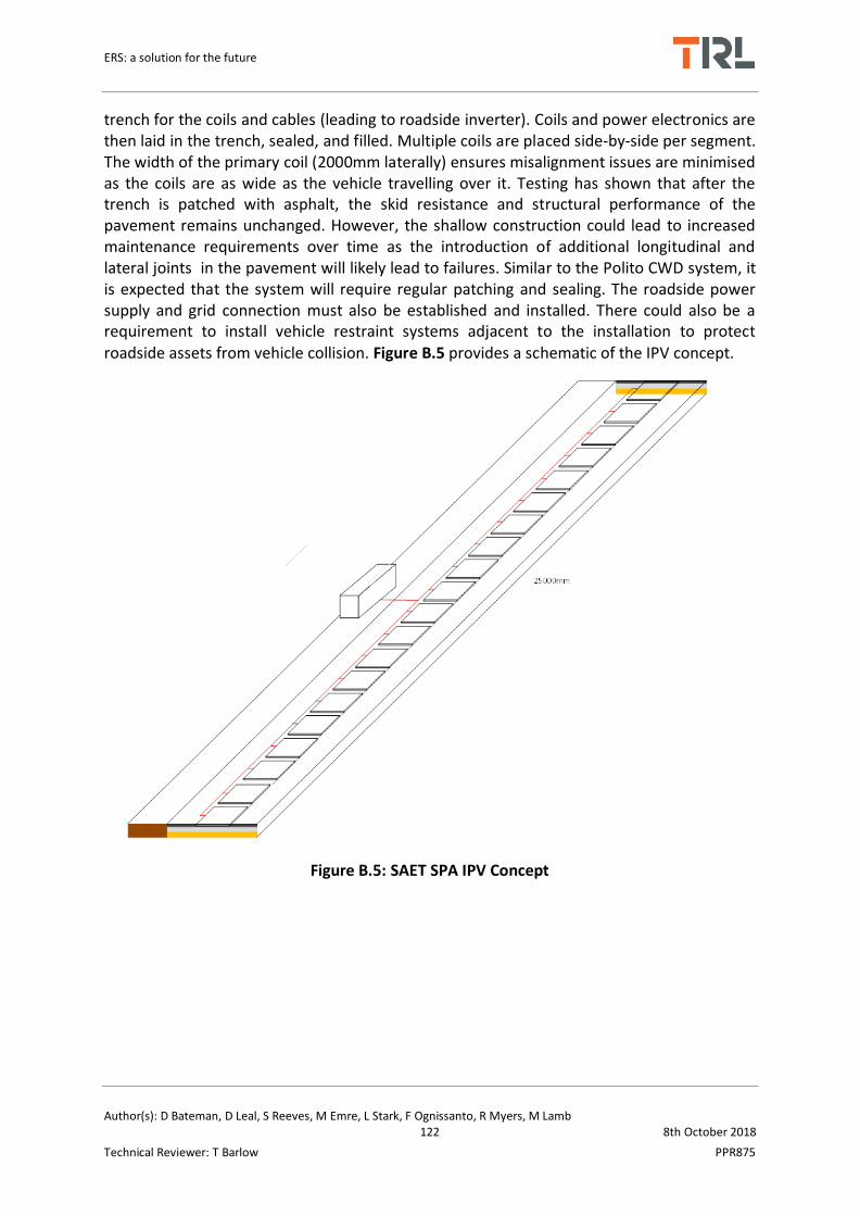
ERS: a solution for the future
Author(s): D Bateman, D Leal, S Reeves, M Emre, L Stark, F Ognissanto, R Myers, M Lamb 122 8th October 2018
Technical Reviewer: T Barlow PPR875
trench for the coils and cables (leading to roadside inverter). Coils and power electronics are then laid in the trench, sealed, and filled. Multiple coils are placed side-by-side per segment. The width of the primary coil (2000mm laterally) ensures misalignment issues are minimised as the coils are as wide as the vehicle travelling over it. Testing has shown that after the trench is patched with asphalt, the skid resistance and structural performance of the pavement remains unchanged. However, the shallow construction could lead to increased maintenance requirements over time as the introduction of additional longitudinal and lateral joints in the pavement will likely lead to failures. Similar to the Polito CWD system, it is expected that the system will require regular patching and sealing. The roadside power supply and grid connection must also be established and installed. There could also be a requirement to install vehicle restraint systems adjacent to the installation to protect roadside assets from vehicle collision. Figure B.5 provides a schematic of the IPV concept.
Figure B.5: SAET SPA IPV Concept

ERS: a solution for the future
Author(s): D Bateman, D Leal, S Reeves, M Emre, L Stark, F Ognissanto, R Myers, M Lamb 123 8th October 2018
Technical Reviewer: T Barlow PPR875
B.4 Bombardier wireless PRIMOVE
PRIMOVE was first developed by Bombardier in 2008/9, more recently collaborations have taken place with a number of vehicle manufacturers, research institutes and local government agencies across Europe. It is a wireless system which operates under the principles of electromagnetic resonance. The system is in commercial use across a number of small bus schemes across Europe. Early iterations of this technology were focused on static charging, for instance, whilst a bus is stationary along its route (opportunistic charging). For earlier cases, the pick-up coil mounted to the underside of the vehicle would lower to make contact with the top of the primary coil, embedded at stop points. More recently the technology has been developed so that it has greater wireless capabilities, removing the need for the pick-up coil having to be lowered to the road surface. This system offers dynamic and static charging capabilities. Accordingly, a large number of the systems operating commercially have been upgraded so that they utilise the enhanced wireless capabilities.
Figure B.6 illustrates Bombardier’s Primove system. The road side power supply is connected to the medium voltage level (10KV) grid connection. The substation collects the 10KV AC from the grid and the transformers step down the voltage level to 400VAC, this process is followed by rectification of 400VAC to 750VDC. 750VDC power is transferred from road side to the underground infrastructure. The underground equipment consists of an inverter, to convert DC voltage to high frequency (20 kHz) wave, segments of loop/coils to transfer the power, and the vehicle detection loops to recognise the vehicles and control electronics to electrify correct segment.
Figure B.6: PRIMOVE System
The PRIMOVE system is currently being applied to passenger vehicles, buses, trams, trains, and heavy goods vehicles. PRIMOVE is made up from three components – charging (in-raod/roadside equipment), battery (on-vehicle battery systems), and propulsion and controls (electrive drive train, signal controls, etc.). The system is compatible with most vehicle types and can be retrofitted. For an overview of the system and its developments please refer to Table B.4.
B.4.1 Recent Developments

ERS: a solution for the future
Author(s): D Bateman, D Leal, S Reeves, M Emre, L Stark, F Ognissanto, R Myers, M Lamb 124 8th October 2018
Technical Reviewer: T Barlow PPR875
Over the last few years there have been a number of important developments with the PRIMOVE system, these include:
Development of “invisible” PRIMOVE (this system does not lower its secondary coil to meet the primary coil)
Retrofitting existing commercial operations with new and improved “invisible” PRIMOVE system. The new systems can operate without the need for the vehicle-mounted secondary coil being lowered to meet the road surface.
Testing PRIMOVE under dynamic conditions Further commercial schemes for buses have been established in a number of
European cities. Existing operations still running successfully, e.g. Braunschweig, Germany scheme
has run for 100,000km and 90,000 charge cycles; installations in Germany, Sweden, and Belgium have travelled 500,000km since installation.
Table B.4: PRIMOVE Overview
Value/Description
Key Parameter Pre-2016 Developments Post-2016 Developments
Manufacturer/IP Owner
Scania/Bombardier Bombardier
System Name PRIMOVE PRIMOVE/eCar/eBus/eVAN
Type of System Static Wireless Power Transfer Static/Dynamic Wireless Power Transfer
Technology Readiness Level (TRL)
2014: TRL 5-6 2018: TRL 5-6
Existing Demonstration Trials/Commercial Schemes/Progress
2008-9: First PRIMOVE prototype developed and tested in Bautzen, Germany. Low floor tram and test track rig tested range of operating frequencies30
2010-12: Bombardier tests dynamic and static WPT (for cars and buses) on test track in Flanders, Belgium. As part of the DRIVE project and Slide-in Electric Road Systems project. 80kW system trialled for bus. 22kW system trialled for car31. Demonstration on City of Lommel bus route – Van Hool 12 m e-bus30,32. 2012 : Funding for PRIMOVE
2016: SCANIA/Bombardier PRIMOVE commercial operation in Sodertalje City, Sweden 40
2017: Braunschweig City, Germany PRIMOVE commercial operation reaches 100,000km and 90,000 charging cycles37,42
PRIMOVE e-buses travel 500,000km since installation across Berlin, Braunschweig, Mannheim, Bruge and Sodertalje. 15 buses (from 4 manufacturers) and 18 charging stations equipped with invisible PRIMOVE42

ERS: a solution for the future
Author(s): D Bateman, D Leal, S Reeves, M Emre, L Stark, F Ognissanto, R Myers, M Lamb 125 8th October 2018
Technical Reviewer: T Barlow PPR875
bus pilot scheme announced in Braunschweig City, Germany, Operated by Braunschweiger Verkehrs-AG . 2013/2014: SCANIA truck equipped with basic PRIMOVE system pick-up, trials on test track Mannheim, Germany29
Commercial Operation of PRIMOVE in Mannheim, Germany33
2015: Bombardier joint venture with leading car manufacturer to install invisible PRIMOVE (static) systems in 3.6kW EV39.
Demonstration Details 2010-12: 125m of sections (made up of 3.6/8.1m segments) on 1.2km of public road installed with PRIMOVE in City Lommel, Belgium30,32. 120kW capability from 750v DC, charging power 40-80kW, efficiency >90%32
2012-2014: 2 Bus PRIMOVE pilot scheme, Braunschweig City, Germany, using 400V AC (input), 200kW operating a 12km route, at 90% efficiency30,36 2013-14: 80kW system trialled for bus. 22kW system trialled for car. 300m long test track containing 4x 20m inductive segments. Mannheim, Germany: WPT Commercial operation of 2 PRIMOVE 200 buses -200kW system, >90% efficiency, 400V AC or 750V DC, 4 charging stations, charging between 2-5 minutes on-route and 15
2016: SCANIA hybrid bus bus, equipped with wireless PRIMOVE enters commercial operation in Sodertalje City, Sweden 40. Bus route 755, 200kW system (static WPT charging during stops). 10km route Design of Z-Mover static charging unit 2017: Braunschweig City, Germany PRIMOVE commercial operation reaches 100,000km37

ERS: a solution for the future
Author(s): D Bateman, D Leal, S Reeves, M Emre, L Stark, F Ognissanto, R Myers, M Lamb 126 8th October 2018
Technical Reviewer: T Barlow PPR875
minutes at depot) across 9km, average speed 13.4km/h 33,34
2015: Commercial operation of PRIMOVE 200 bus in Bruge, Belgium38
Total Cost (€/lkm) 2014: €3.25m/lkm (£2.55 in 2014)5
€1.7m/lkm (final expectation)5
2017: €3.62m-€6.15m/lkm45
€700k/km (grid connections, substations)45
Operation Cost (€/years)
unknown 2017: Annual maintenance cost =1-2% of total capital cost.45
System Voltage (V), Current (A), Power Factor (PF), Quality Factor (QF), Specific Power/Specific Energy Ratio (SP/SE), Frequency (kHz)
10kV (input) three phase AC 750v DC (output), 400A/phase,
Overall System Efficiency
2012: >90%32
2014-15:80-90%5 2017: 68.8-77.4%45 2018: 90% but not clarified45
Power (kW), Power Rating/Range
2012-12: 120kW32
2014: 200kW
2016-18: 150-200kW
Air Gap (cm) 2015: 2cm 2018: 2cm
Communication Protocol
Antenna loop between road and vehicle
Antenna loop between road and vehicle
EM Compatibility/Frequency/Exposure
2008-14: Meets all EN standards, in accordance with TÜV SÜD testing for EMF and EMC5,43. Em exposures less than 6.25µT5.
2018: Meets all EN standards, in accordance with TÜV SÜD testing for EMF and EMC5,43. Em exposures less than 6.25µT5.
Maximum Vehicle Speed (km/h)
2014: 13.4km/h34 2017: 50km/h45
Installation Description (method, time, cost)
2017: Excavate trench 800x40mm45
System Maintenance Requirements
5000 hours of use estimated between servicing and maintenance interventions
Operational Tolerances (temperature, pressure, vibration)
Temperature: -400C to +400C Temperature: -400C to +400C

ERS: a solution for the future
Author(s): D Bateman, D Leal, S Reeves, M Emre, L Stark, F Ognissanto, R Myers, M Lamb 127 8th October 2018
Technical Reviewer: T Barlow PPR875
Foreign Object Detection
Yes, automatic metal detection between primary and secondary coils for 3.6kW eCar PRIMOVE41
Effective Misalignment (xyz)
X= 100-150mm45 (large efficiency reductions at 200-250mm)
B.4.2 Installation and Maintenance
For dynamic application, 20m segments, containing a number of individual primary coils, are used. A trench 200mm deep, by 800mm wide is cut. Most components are prefabricated, speeding up construction time. Primary coils, antennas, junctions and connection leads are placed inside the trench and secured. Once the hardware is in the place the road can be resurfaced. The primary coil is located approximately 40mm below the road surface. Roadside equipment can be placed far enough from the roadside so that the installation of vehicle restraint systems is not necessary. The width of the primary coil is minimises misalignment issues.
With regards to maintenance the system itself is designed to withstand loading from traffic. While no estimation is provided as to the systems expected lifetime the static charging installations have been in place for several years without fault.. If frequent maintenance is not carried out (i.e. resurfacing) this could lead to the system being damaged prematurely.
The cost of annual maintenance is assumed to be 1-2% of the overall capital cost.

ERS: a solution for the future
Author(s): D Bateman, D Leal, S Reeves, M Emre, L Stark, F Ognissanto, R Myers, M Lamb 128 8th October 2018
Technical Reviewer: T Barlow PPR875
B.5 VEDECOM Qualcomm HALO
The Qualcomm HALO DEVC is a wireless inductive system that was developed for static use but has since demonstrated dynamic capabilities. The system uses electromagnetic field resonance to transfer power between the primary coil (a low profile pad placed on the road surface), and the secondary coil mounted to the vehicle underside. Both pads are magnetically coupled. Power is converted to DC by the on-board controller and used to charge the vehicle’s batteries.
Qualcomm have demonstrated their dynamic system in May 2017 as part of Fabric project. Two vehicles equipped with power transfer coils were used to test the dynamic power transfer. The system was designed to transfer power at 20kW at highway speeds. The demonstration was successful and Qualcomm system have transferred power coils embedded in the road onto the coils places under the vehicle.
Value/Description
Key Parameter Pre-2016 Developments Post-2016 Developments
Manufacturer/IP Owner
Qualcomm Qualcomm
System Name Qualcomm HALO Qualcomm HALO
Type of System Dynamic Wireless Power Transfer Dynamic Wireless Power Transfer
Technology Readiness Level (TRL)
2014: TRL4 2015: TRL4
2017:TRL 3-4
Existing Demonstration Trials/Commercial Schemes/Progress
2014:
2015:
2017: Fabric Project trial, Satory versailles test site, France.
Demonstration Details 2014-15: Static Trials, London5 2015:
2017: 100 metre dynamic power transfer track consisted of four 25 metre segments, equipped with 56 charging pads.Transferring 20kW power.
System Voltage (V), Current (A), Power Factor (PF), Quality Factor (QF), Specific Power/Specific Energy Ratio (SP/SE), Frequency (kHz)
300-400V AC, 67A, ?PF, ?QF, ?SP/SE, 85kHz
400 V, A, ?PF, ?QF, ?SP/SE, 20kW, 85khz
Overall System

ERS: a solution for the future
Author(s): D Bateman, D Leal, S Reeves, M Emre, L Stark, F Ognissanto, R Myers, M Lamb 129 8th October 2018
Technical Reviewer: T Barlow PPR875
Efficiency 2015: 80% (expected)
Power (kW), Power Rating/Range
2015: 20kW5
2017:20 kW 2
Air Gap (cm) 2015: 125-175mm5 2017: 175 mm 2
Communication Protocol
CAN
EM Compatibility/Frequency/Exposure
2018: 2.27uT maximum at worst case. 4.06uT inside the cabin
Maximum Vehicle Speed (km/h)
2014: 60km/h5 2018:100km/h
Installation Description (method, time, cost)
2014: System is currently mounted flush with the road surface (expected to be buried beneath road surface)
2016: 2017: in flush with the road. A trench excavated in the middle of the road, the excavation is supported by concerete and equipment is installed in the trench. The final process is to cover the trench with a concrete slab,which contains power transfer coil. 2018:
Estimated System Lifetime
2014:
2016:
Foreign Object Detection
Driver visual inspection of track only. No automatic detection.
In static charge mode HALO can detect foreign objects.
Effective Misalignment (xyz)
Y = ±200mm5 Y= ±200mm
B.5.1 Installation and Maintenance
The test track pavement was built on 100m long stretch of dedicated tarmac pavement.
The roadway consists of:
• A 100m long (four 25 metre segments), 4m wide tarmac road, built according to roadway
standards
• In the centre of the roadway, a 0.8m wide concrete trench containing the charging coils
and electronics

ERS: a solution for the future
Author(s): D Bateman, D Leal, S Reeves, M Emre, L Stark, F Ognissanto, R Myers, M Lamb 130 8th October 2018
Technical Reviewer: T Barlow PPR875
• Slab covers which were placed and fixed by bolts to cover the trench
• Power was transferred to the charging coils via two power conduits, introduced from the side of the roadway into the trench.
The concrete trench was divided by joints in a number of sections of about 7 m long each to avoid shrinkage cracking. The number of necessary bolts used to fix slab covers was determined based on the most unfavourable loads applied by a vehicle on the slab covers. A cross section of the pavement is shown in Figure 8 with a 3D image of the concrete base with slab covers shown in Figure 9.
The dimensions of one slab cover are 1750×1000×30 mm3 (Figure 10). That means for one concrete base section of 7 m long, there are 4 slab covers. Detailed FEA analysis of the stresses imposed by test vehicles was carried out in to ensure the slab covers were adequate for the task and this was reported in D4.5.2. Figure 11 shows the completed construction of the test track in August 2015

ERS: a solution for the future
Author(s): D Bateman, D Leal, S Reeves, M Emre, L Stark, F Ognissanto, R Myers, M Lamb 131 8th October 2018
Technical Reviewer: T Barlow PPR875
B.6 Oak Ridge National Laboratory
Oak Ridge National Laboratory (ORNL) has been the project lead for a number of multi-year research programmes focused on Wireless Power Transfer (WPT), funded by the U.S. Department of Energy46,47 (DOE). From 2010-2012, ONRL developed a proof-of-concept 6.6kW WPT system for static charging with an efficiency of 85%47 (under VSS061 contract for $1m) for plug-in electric vehicles. From 2012-2015 they built on earlier work, in collaboration with Toyota Motor Co. (CRADA), Evatran (Plugless Power), Clemson University ICAR, Duke Energy and CISCO Systems received funding for $8m from the U.S. DOE (under contract VSS103, partners funded $3.3m also). The aim of this project was to advance technology maturity, identify feasible commercial avenues, improved standardisation, and improve safety, interoperability, system integration within existing EV models. The system uses electromagnetic field resonance to transfer power from a primary coil (in/above ground) to the secondary coil (vehicle integrated). It should be noted that WPT is not a commercial system at this stage. An overview of WPT is provided in Table B.5. Figure B.7: ORNL WPT Concept provides an illustration of the WPT concept and components.
Figure B.7: ORNL WPT Concept
B.6.1 Recent Developments
WPT has been designed and tested on a number of commercially available vehicles. Earlier iterations of this technology were used as proof of concept in static applications. However, more recent work has demonstrated its ability to perform under dynamic conditions. Recent
developments include:
Continued integration of WPT to commercial vehicles48

ERS: a solution for the future
Author(s): D Bateman, D Leal, S Reeves, M Emre, L Stark, F Ognissanto, R Myers, M Lamb 132 8th October 2018
Technical Reviewer: T Barlow PPR875
Continued testing of 20kW Toyota RAV448 system. Successful small scale dynamic tests carried out
Parametric sensitivity analysis of key parameters: primary side compensation capacitance, coupling coefficient, transformer leakage inductance, load conditions53
Research to develop coil sizing guidelines dependant on vehicle speed and power requirements (using experimental data), to ensure suitable operation54
Research/modelling into the effects of resonant network characteristic and control variables on the dc-link capacitor of a wireless charger55
Development of inductively coupled multiphase resonant converter (instead of traditional frequency and phase shift control techniques)56
Development/optimisation of power transfer control protocol57 Development of V2G/G2V applications58
Table B.5: ORNL WPT Overview
Value/Description
Key Parameter Pre-2016 Developments Post-2016 Developments
Manufacturer/IP Owner ORNL ORNL
System Name Wireless Charging of Electric Vehicles (WCEV)
Wireless Power Transfer (WPT)
Type of System Static Wireless Power Transfer
Static/Dynamic Wireless Power Transfer
Technology Readiness Level (TRL)
TRL 3-4 TRL 3-4
Existing Demonstration Trials/Commercial Schemes/Progress
2010-13: Coil design, tested at 7kW (Laboratory demonstration)46 Design and fabrication of prototype power inverter and roadside electronic components46 Validate power flow control algorithm with prototype inverter46 Communication development, Can gateway to vehicle battery management system WPT control systems (laboratory demonstration) Full system trial (laboratory
2016: Continued integration of WPT to commercial vehicles48 Continued testing of 20kW Toyota RAV448 system. Successful small scale dynamic tests carried out Parametric sensitivity analysis of key parameters: primary side compensation capacitance, coupling coefficient, transformer leakage inductance, load conditions53 Research to develop coil sizing guidelines dependant on vehicle speed and power requirements (using experimental data), to ensure suitable operation54 2017: Research/modelling into

ERS: a solution for the future
Author(s): D Bateman, D Leal, S Reeves, M Emre, L Stark, F Ognissanto, R Myers, M Lamb 133 8th October 2018
Technical Reviewer: T Barlow PPR875
demonstration)45 Exploring WPT losses from encasing in concrete and asphalt52 2014-15: Integration of WPT system into commercial PEV (Toyota Prius. RAV4, Scion IQ-EV, Chevy Bolt)51 Deployment and demonstration of 6.6kW system Development of 20kW system for Toyota RAV45
the effects of resonant network characteristic and control variables on the dc-link capacitor of a wireless charger55 Development of inductively coupled multiphase resonant converter (instead of traditional frequency and phase shift control techniques)56 Development/optimisation of power transfer control protocol57 Development of V2G/G2V applications58
Demonstration Details 2016: Toyota RAV4 tested dynamically along 3.16m laboratory track, coils spaced 0.79m apart – only tested with 2 primary coils48.
Estimated Total Cost (€/lkm)
€1,484,40050 (hardware + installation + labour cost = €1.32m ( $2.8m/mile in 2014); power grid connection = €165k ($350k/mile in 2014) – note maintenance + operational cost not included, cost estimated for dynamic system. Prototype system $10,000 (equipment only)5
Unknown, system is still under development. No further economic studies from ORNL found in existing literature.
System Voltage (V), Current (A), Power Factor (PF), Quality Factor (QF), Specific Power/Specific Energy Ratio (SP/SE), Frequency (kHz)
Toyota RAV4:220V AC, 45A, 0.98PF, 22-144kHz5
220V AC, 45A, 0.98PF, 22-144kHz5
Overall System Efficiency Toyota RAV4: 85.2-89.5% (6.6kW)49
Toyota RAV4 = 88% 5 (20KW)
Scion iQ-EV: 85.5%48
Toyota RAV4: 90-95%48,49(20kW)
Power (kW), Power Toyota RAV4: 6.6-7.8kW48 Scion iQ-EV: 6.9kW48

ERS: a solution for the future
Author(s): D Bateman, D Leal, S Reeves, M Emre, L Stark, F Ognissanto, R Myers, M Lamb 134 8th October 2018
Technical Reviewer: T Barlow PPR875
Rating/Range Toyota RAV4: 20kW5,48
Toyota RAV4: 14kW51
Toyota Prius: 2.5kW51
Air Gap (cm) Toyota RAV4: 16cm5,48
Scion iQ-EV: 16.5cm48
Toyota RAV4: 16.2cm48
EM Compatibility/Frequency/Exposure
B = 0.59µT, E = 3.53V/m, THD = <4%5
B = 2.47µT, E = 1.57V/m. Exposure below ICNIRP limits59
Maximum Vehicle Speed (km/h)
Development heavily centred on static applications
Toyota RAV4: 80km/h (assumed)48
Installation Description (method, time, cost)
Anticipated that system will be installed beneath road surface (depth unknown) – early stages of development5
Still under development, dynamic testing only in laboratory using raised wheel tracks. Tests have been carried out to determine optimum materials for installation.
System Maintenance Requirements
Little discussion of maintenance in literature
Little discussion of maintenance in literature
Estimated System Lifetime
20 years (coil/loop)
Assumed to be the same
Foreign Object Detection Optical and visual sensing system5
Same system assumed to be in use
Effective Misalignment (xyz)
X = 12cm X = 12cm
B.6.2 Installation and Maintenance
The dynamic system has only been tested under laboratory conditions to-date. These experiments used a raised wheel track, with the primary coils being flush with the wheel paths. The system is intended to be installed beneath the road surface. As this system is still under development its final form and construction is uncertain and subject to change. The team at ORNL have been experimenting with alternative materials, casings and construction techniques. The primary and secondary coils are comprised of: gauge alunimum shielding plates for EM safety, an aluminium structural plate that supports the ferrite plates, litz cable coil, and a plastic casing for protection against moisture/dirt

ERS: a solution for the future
Author(s): D Bateman, D Leal, S Reeves, M Emre, L Stark, F Ognissanto, R Myers, M Lamb 135 8th October 2018
Technical Reviewer: T Barlow PPR875
B.7 Conductix-Wampfler IPT
Inductive Power Transfer (IPT) is a concept for wireless static charging developed by Conductix-Wampfler GmbH and is commercialised by their daughter company IPT Technology GmbH. Similar to other wireless systems the IPT solution employs electromagnetic field resonance between two coils; primary coils are installed in the road, and secondary coils are located on the vehicle underside. The system has been in commercial use for over a decade for vehicle charging. Current commercial applications are limited to buses, and use the system for opportunistic charging, as well as overnight charging at depots.
As illustrated in Figure B.8, the systems components can be grouped into three sections: power electronics module, inductive module, and vehicle module. The power electronics consist of an AC source (grid connection), a rectifier to convert AC to DC, a variable frequency generator, an amplifier, and a high voltage transformer. These deliver power to the primary coil. As the secondary coil, mounted to the vehicle underside, aligns with the primary coil, inductive coupling begins. Power is then transferred to the vehicle via its AC to DC power receiver which charges the on-board battery unit. The roadside power electronics also include a cooling unit. The latest system is highly modular and flexible allowing for a number of system variations and installation layouts. Depending on the power requirements of the vehicle, multiple pick-ups can be installed, from 2-6 50kW units. An overview of the system is provided in Table B.6.
Figure B.8: IPT System
B.7.1 Recent Developments
The system has seen a number of developments of the last few years, these include:
Additional commercial schemes implemented in the Netherlands, UK, and Spain using hybrid and electric buses retrofitted with on-board IPT systems.
Development and laboratory testing of IPT-Charge for dynamic applications Continued successful operation of IPT bus schemes in Italy, Netherlands, UK and
Spain, with plans to add significant numbers of IPT fitted buses to their current fleets Development and implementation of 100-300kW IPT Increased air gap from 4cm to 13-15cm. Previous systems lowered the secondary coil
to the road surface; however newer systems have eliminated this feature.

ERS: a solution for the future
Author(s): D Bateman, D Leal, S Reeves, M Emre, L Stark, F Ognissanto, R Myers, M Lamb 136 8th October 2018
Technical Reviewer: T Barlow PPR875
Table B.6: IPT Overview
Value/Description
Key Parameter Pre-2016 Developments Post-2016 Developments
Manufacturer/IP Owner
Conductix-Wampfler GmbH (parent company) IPT Technology GmbH (spin-off company, founded in 2014 to focus on IPT applications to transport industry)60
Conductix-Wampfler GmbH/IPT Technology GmbH60
System Name Inductive Power Transfer (IPT) Charge
Inductive Power Transfer (IPT) Charge
Type of System Inductive, static in-road (pick-up coil lowered to near road surface)
Inductive, static in-road (dynamic under trial)
Technology Readiness Level (TRL)
TRL9 (static application)5 TRL9 (static)5
Existing Demonstration Trials/Commercial Schemes/Progress
1998: Demonstration trial EV shuttle using IPT – Rotorua, New Zealand132
2002-3: 8 Electric Buses (operating commercially) retrofitted with IPT for static charging – Geona, Italy 23 Electric Buses (operating commercially) fitted with IPT for static charging across 200km route – Turin City, Italy 2014-15: 3 Electric Buses (operating commercially) fitted with IPT for static charging along 180km route – Utrecht, Netherlands 8 Electric Buses (operating commercially) fitted with IPT for static charging along 48km route – Milton Keynes, UK 3 Electric Buses (operating commercially) fitted with IPT for static charging along 22km route – London, UK
2016: 1 Electric bus (converted diesel Volvo) in commercial operation after 2012 demonstration trial - s’Hertogenbosch, Netherlands 2 hybrid buses fitted with IPT (operating commercially) – Bristol, UK Development and laboratory testing of IPT-Charge for dynamic application62 2018:5 hybrid buses in commercial operation across 14km route for static charging- Madrid, Spain (Plans to add 15 buses & 18 minibuses in late 2018. A further 40 buses to be introduced from 2019-2020) All commercial bus operations (since 2002) are still active and expanding.

ERS: a solution for the future
Author(s): D Bateman, D Leal, S Reeves, M Emre, L Stark, F Ognissanto, R Myers, M Lamb 137 8th October 2018
Technical Reviewer: T Barlow PPR875
Estimated Total Cost (€/lkm)
unknown 20kW e-Bus: €163K61
Infrastructure cost: €143k61 (for a scheme of 11 e-buses) – excluding installation, labour and maintenance
Operation Cost (€/years)
Fuel savings: €15K-18K per bus per annum63
57-82% fuel saving compared to diesel65
System Voltage (V), Current (A), Power Factor (PF), Quality Factor (QF), Specific Power/Specific Energy Ratio (SP/SE), Frequency (kHz)
400V AC (input)/600V DC (output), 101A, 0.92PF, ?QF, ?SP/SE, 20kHz5 (per 30kW module)5
415V AC (input)/600V DC (output), 83A 0.92PF, ?QF, ?SP/SE, 20kHz (per 50kW module)
Overall System Efficiency
93% 93%
Power (kW), Power Rating/Range
60kW (2 x 30kW per module) up to 200kW (in array)
100-300kW (variants of 50kW modules)
Air Gap (cm) 4cm5 (pick-up unit lowers to meet road surface)
13-15cm66
Communication Protocol
FHSS via Ethernet & Wireless data transmission5
Ethernet, digital I/O,CAN (variable I/O’s) & radio modem
EM Safety Meets EN55011- Class A1 & B(conducted &radiation), EN61000-2,-3-4 (immunity & harmonics), ICNIRP 2010 (exposure)5
Meets all standards
Vehicle Speed (km/h) Static charging only (average bus speed varies, typically 25km/h)
26km/h64 (average speed) 0km/h (charging speed)
System Maintenance Requirements
Periodical maintenance encouraged for maximum longevity
Periodical maintenance encouraged for maximum longevity, flexible component placement to suit specific maintenance requirements (i.e. Track supply unit embedded in-road/footpath/roadside unit for ease of access).
Estimated System Lifetime
Vehicle Battery: 5 years (although possibly longer)61
System Details( inroad, on-vehicle, roadside)
In-road: Prefabricated reinforced concrete housing pre-mounted cables, terminal box, energy guiding chain, lid

ERS: a solution for the future
Author(s): D Bateman, D Leal, S Reeves, M Emre, L Stark, F Ognissanto, R Myers, M Lamb 138 8th October 2018
Technical Reviewer: T Barlow PPR875
seal66 (3100x1550x1030mm); charge module road pad insert (3000x1450x805mm) per module Roadside: Monitoring & cooling units (project specific, typically unit 1900x2000x500mm)5,66 On-vehicle pick up: (1023x875x60mm)
Operational Tolerances (temperature, pressure, vibration)
Temperature: -200C to +450C5 Vibration: 3mm (2-9Hz)
Effective Misalignment (xyz)
X = 40mm, Y= 40mm, Z = 10mm5
Structural Integrity (max load, K=kN)
400kN5
B.7.2 Installation and Maintenance
Aside from power connections, the system is completely prefabricated, allowing for relatively straightforward installation. Firstly, the road space where the primary coils are to be installed needs to be excavated to a depth of approximately 3m. Grid connections and roadside electronics are installed and cables placed. The primary coil housing unit is lowered and secured into the excavation. The primary coil charging unit is then inserted into the housing. The road around the installation can then be resurfaced or patched. Figure B.9 shows the charging unit being lowered into its housing.
Figure B.9: IPT Installation (Source: IPT Technologies)

ERS: a solution for the future
Author(s): D Bateman, D Leal, S Reeves, M Emre, L Stark, F Ognissanto, R Myers, M Lamb 139 8th October 2018
Technical Reviewer: T Barlow PPR875
There are a number of variations of where equipment can be placed depending on the type of installation and the unique site spatial requirements, these are illustrated in Figure B.10, where: (1) charge pad (primary coil), (2) track supply, (3) monitoring unit, (4) cooling unit, (5) PFC stage, (6) inverter module.
(Layout A) (Layout B)
(Layout C)
Figure B.10: IPT Layout Variations – Layout A (top left), B (top right), C (bottom) (Source: IPT Technologies)
Figure B.10 layout A and B offer maximum discretion and minimum visibility and would be typically used at bus stops, terminus points and at junctions. Layout C houses the track supply, power electronics, and cooling unit all in one space. This layout would be most suitable for applications where deep excavations are not possible and where roadside space permits a larger housing unit to be installed. It is also possible to connect multiple charge pads to one set of power electronics so two buses can charge simultaneously.

ERS: a solution for the future
Author(s): D Bateman, D Leal, S Reeves, M Emre, L Stark, F Ognissanto, R Myers, M Lamb 140 8th October 2018
Technical Reviewer: T Barlow PPR875
B.8 Siemens/Scania eHighway
The Siemens e-Highway concept is a conductive dynamic solution, utilising overhead catenaries that transfer power directly to the vehicles on-board systems (battery or traction unit) via an automatic pantograph. This system is essentially an adaption and evolution of railway electrification and trolleybus systems. Dissimilar to rail however, the e-Highway pantograph has two points of contact with the overhead power lines to ensure the system is grounded. The system has been in development and testing since early 2010 and currently has a number of active demonstration trials in Europe, Scandinavia and the USA. Siemens e-Highway are currently actively involved in a number of research and development programme, collaborating with a number of Universities, Research Institutes, Governments and other private organisations. These demonstrations and research initiatives aim to commercialise, improve and promote the technology to various stakeholders (including other road users, freight industry and NRAs). The e-highway concept is the most mature conductive catenary solution to-date. Currently the system is still under development and subject to further testing and refinement, with research projects commissioned until 2021.
The basic operating principles are as follows; roadside substations (housing medium voltage DC switching system, a power transformer, a rectifier, and a controlled inverter for regenerative braking) transfer power from the grid to the overhead transmissions wires. Once a vehicle has entered the charging lane its pantograph (located on the roof of the driving cab) automatically connects to the overhead wires. Power is then transferred to the vehicles traction system or battery; this is controlled by the vehicles on-board unit (OBU) and operations and control centre (OCC). The pantograph has automatic and manual functions, freely making contact with, and retracting from, the overhead wires. The vehicle is able to move freely in and out of the charging lane and can detach rapidly, in cases where evasive manoeuvres are required. This system is only compatible with heavy duty vehicles (HDVs), given the height of the overhead lines (approx. 5-6m from the road surface). A picture of the system in-use can be seen in Figure B.11.
Figure B.11: eHighway Concept (Source: Siemens)
The system can support a number HDV types, using various propulsion mechanisms. For instance it is possible to retrofit and adapt diesel, biofuel, CNG/LPG and hydrogen fuel cell

ERS: a solution for the future
Author(s): D Bateman, D Leal, S Reeves, M Emre, L Stark, F Ognissanto, R Myers, M Lamb 141 8th October 2018
Technical Reviewer: T Barlow PPR875
vehicles for use in the system. It can support vehicles with small-large batteries and fuel cells, small-large combustion engines, and various drive systems (parallel hybrid, serial hybrid or full electric). Adaptations can be made to 2-3 axle tractor trucks and 2-4 axle rigid trucks. However it should be noted that retro fitting existing vehicles is less economic, in the long term, than purchasing a new EV truck fully equipped with the system (Scania recently announced that they can produce and supply brand new e-Highway compatible vehicles). An overview of the eHighways system and developments is presented in Table B.7. The concept is suitable for closed-systems (cargo transfer between port and depot, mining, etc.) and is also capable of working in an open system (highways) where continuous sections can be installed.
B.8.1 Recent Developments
Since its initial development and trial on the 2.1km test track in Berlin, Germany, there have been a number of important developments. These include:
Pilot 2km eHighway installed on public road (E16 highway) Stockholm, Sweden68
using Scania vehicles. This is a 2 year demonstration Part of ELANO (2016-2019) consortium for R&D into catenary road systems for
heavy duty vehicles74 Pilot 1.6km eHighway, with overhead lines in both directions, California, USA68 Pilot 10km e-Highway commissioned69 on public road between Frankfurt Airport
and Darmstadt/Weiterstadt interchange. Construction almost complete at time of writing127.
Part of FESH I & II consortium (2017-2021) constructing 12km of e-Highway in Holstein, Germany75
Development and planning of 30-40km installation in Sweden
Table B.7: Siemens eHighway Overview
Value/Description
Key Parameter Pre-2016 Developments Post-2016 Developments
Manufacturer/IP Owner
Siemens Siemens
System Name e-Highway e-Highway
Type of System Dynamic Conductive Power Transfer
Dynamic Conductive Power Transfer
Technology Readiness Level (TRL)
TRL 7-8 TRL7-872
Existing Demonstration Trials/Commercial Schemes/Progress
2010-12: Proof of concept, testing 2.1km installation on private test track in Berlin, Germany68
2016: Pilot 2km eHighway installed on public road (E16 highway) Stockholm, Sweden68 using Scania vehicles. 2 year demonstration

ERS: a solution for the future
Author(s): D Bateman, D Leal, S Reeves, M Emre, L Stark, F Ognissanto, R Myers, M Lamb 142 8th October 2018
Technical Reviewer: T Barlow PPR875
Part of ELANO (2016-2019) consortium for R&D into catenary road systems for heavy duty vehicles74
2017: Pilot 1.6km eHighway, with overhead lines in both directions, California, USA68 Pilot 10km e-Highway commissioned69 on public road between Frankfurt Airport and Darmstadt/Weiterstadt interchange. Construction of 10km eHighway on A5 Autobahn nearly complete127. Part of FESH I & II consortium (2017-2021) constructing 12km of e-Highway in Holstein, Germany75
Total Cost (€/lkm) €1.07m-2.06m/lkm5,67 €2.2m/lkm71 €1.8m/lkm73 (construction of overhead lines) €0.4m/lkm73 (connection to power grid, including transformers)
Operation Cost (€/years)
€20k fuel saving per 40 tonne truck per 100,000km68 Maintenance cost approx. 2.5% of investment per year71
System Voltage (V), Current (A), Power Factor (PF), Quality Factor (QF), Specific Power/Specific Energy Ratio (SP/SE), Frequency (kHz)
750V DC 750V DC
Overall System Efficiency
90-97%5 80-85%68
Power (kW), Power Rating/Range
200kW Up to 500kW
Maximum Vehicle 90km/h5,68 (target speed) 80km/h80 (tested speed)

ERS: a solution for the future
Author(s): D Bateman, D Leal, S Reeves, M Emre, L Stark, F Ognissanto, R Myers, M Lamb 143 8th October 2018
Technical Reviewer: T Barlow PPR875
Speed (km/h)
Installation Description (method, time, cost)
The usable catenary length is approx. 2.0 km. The contact wire distance between pPlus and minus pole is unchanged at 1.35 m. Both Kettenwerke consist of one each 10 kN tensioned suspension cable of the copper-magnesium alloy BzII with 120 mm² cross-section and a 20 kN post-stressed magnesium alloyed copper trolley RiM 150 mm² (CuMg0.5). The Post-tensioning of the conductor takes place via a weight-adjusting device.76
For details of A5 Autobahn installation please refer to
Estimated System Lifetime
- 10 years
System Details( inroad, on-vehicle, roadside)
Roadside: Substations equipped with medium voltage switchgear, power transformers, rectifiers, controlled inverters On-vehicle: Active pantograph (automatically adjusts, connects and disconnects from overhead lines)
System components remain the same Overhead lines mounted from hanging beams 5.15m above ground, 1.35m apart. 750V DC power supply feed in points every 1-4km70,76
Foreign Object Detection
Not required Not required, extremely difficult to introduce foreign objects between pantograph and overhead lines. Pantograph can detract from lines automatically for evasive driving manoeuvres
B.8.2 Installation and Maintenance

ERS: a solution for the future
Author(s): D Bateman, D Leal, S Reeves, M Emre, L Stark, F Ognissanto, R Myers, M Lamb 144 8th October 2018
Technical Reviewer: T Barlow PPR875
The majority of the installation is done at the roadside resulting in minimal disruptions to traffic. Firstly, geotechnical and geophysical surveys are carried out to ensure the site is free from hidden obstructions, and also to establish the type of foundations required for the masts. Once the site has been surveyed and plans designed, installation can begin. Excavations for masts are carried out and their steel reinforced concrete foundations are laid and left to cure. This can take approximately one month. Masts are erected at regular spacing, i.e. 50m intervals. Cables are then fed and looped through each mast and tensioned. This requires a minimal road closure. Roadside power electronics are installed and grid connections are established. The installation technique is essentially the same as it would be for overhead lines in rail applications. As such the installation process is fairly well established, uses non specialist plant; and given the nature of limited time on-site during rail installations, can be undertaken fairly quickly. The eHighways concept does not interfere with the pavement structure in any way. As such, all pavement properties remain unchanged. i.e. skid resistance and surface texture, structural integrity etc.
The system requires very little maintenance and this has been proved through demonstration trials that have been running for the last few years. The system has been proved to work under heavy snow and ice conditions in Sweden, and in hot, earthquake prone locations such as California, USA. In cold environments, to prevent ice build-up on the power cables, a large current is sent through the overhead lines. This heats up the cables and melts ice/snow build-up. The system can operate fully in rainy conditions also. The masts are designed to withstand significant wind loading. As such maintenance is limited to routine safety inspections, checking the integrity of components (all of which have 10+ year service lifetimes) and the tensioning of the wires. Diagnostics can be undertaken remotely and if required the system, or affected segment, can be switched off immediately. The system has an estimated lifespan of 10 years, however in practice it is expected to last much longer. By comparison, Sweden’s first overhead rail electrification lines where installed over 100 years ago and are still in operation today.

ERS: a solution for the future
Author(s): D Bateman, D Leal, S Reeves, M Emre, L Stark, F Ognissanto, R Myers, M Lamb 145 8th October 2018
Technical Reviewer: T Barlow PPR875
B.9 Elways AB/NCC/eRoadArlanda
Elways AB, in partnership with a number of organisations and government bodies, have developed a conductive dynamic solution that uses electrified rails inserted into the road. Power transfer from the rail to the vehicles on-board systems requires the use of movable pick-up arm, located at the rear of the vehicle. The arm automatically detects the presence of the rail, communicates with the power electronics to lower itself to securely connect with the rail. This then allows power to be transferred and charges the vehicles on-board battery. The arm automatically detracts from the rail if evasive or overtaking manoeuvres are sensed. Communications with the vehicles BMS allow calculation of power consumption from which the user can be debited accordingly. The concept is illustrated in Figure B.12.
Figure B.12: Elways Concept
Rails are segmented; meaning only the section the vehicle is travelling over is electrified. Furthermore the actual conductive contact points are located at the bottom of the rail, approximately 6cm deep. This means that the top of the rail (in a safety context, i.e. for motorcyclists) is not charged. Additionally the rails are only electrified if the vehicle is travelling above a certain velocity. If the vehicle speed drops below this threshold the system will deactivate. A picture of the system in operation can be seen in Figure B.13. An overview of the system is provided in Table B.8.
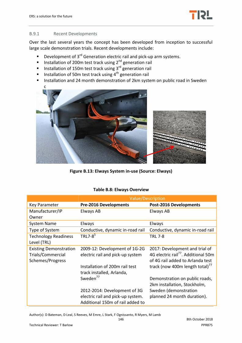
ERS: a solution for the future
Author(s): D Bateman, D Leal, S Reeves, M Emre, L Stark, F Ognissanto, R Myers, M Lamb 146 8th October 2018
Technical Reviewer: T Barlow PPR875
B.9.1 Recent Developments
Over the last several years the concept has been developed from inception to successful large scale demonstration trials. Recent developments include:
Development of 3rd Generation electric rail and pick-up arm systems. Installation of 200m test track using 2nd generation rail Installation of 150m test track using 3rd generation rail Installation of 50m test track using 4th generation rail Installation and 24 month demonstration of 2km system on public road in Sweden
c
Figure B.13: Elways System in-use (Source: Elways)
Table B.8: Elways Overview
Value/Description
Key Parameter Pre-2016 Developments Post-2016 Developments
Manufacturer/IP Owner
Elways AB Elways AB
System Name Elways Elways
Type of System Conductive, dynamic in-road rail Conductive, dynamic in-road rail
Technology Readiness Level (TRL)
TRL7-85 TRL 7-8
Existing Demonstration Trials/Commercial Schemes/Progress
2009-12: Development of 1G-2G electric rail and pick-up system Installation of 200m rail test track installed, Arlanda, Sweden77
2012-2014: Development of 3G electric rail and pick-up system. Additional 150m of rail added to
2017: Development and trial of 4G electric rail77. Additional 50m of 4G rail added to Arlanda test track (now 400m length total)77 Demonstration on public roads, 2km installation, Stockholm, Sweden (demonstration planned 24 month duration).

ERS: a solution for the future
Author(s): D Bateman, D Leal, S Reeves, M Emre, L Stark, F Ognissanto, R Myers, M Lamb 147 8th October 2018
Technical Reviewer: T Barlow PPR875
Arlanda test track77
Estimated Total Cost (€/lkm)
Estimated: €4.66m/lkm5
Projected: €73,700 - €501,000/lkm for 477km installation (130kV-30kV)82
Current Estimate: €450k-1m/lkm79,83
Projected Estimate: €391,680/lkm (projected cost based on implementing 20,000km of conductive rail roads78
Pick-up: €500-1000 per unit
Operation Cost (€/years)
Annual maintenance cost = 1-2% of total capital investment82
– However low voltage systems require less maintenance so this may not be reflective of actual maintenance expenditure
€157k/lkm fuel saving per year78
€3.13bn annual fuel saving (compared against fossil fuels) across 20,000km of conductive rail network78 Annual maintenance cost: €2,100/lkm83
System Voltage (V), Current (A), Power Factor (PF), Quality Factor (QF), Specific Power/Specific Energy Ratio (SP/SE), Frequency (kHz)
400-800V AC, 250A 400-800V AC, 250A
Overall System Efficiency
82-95%5,81 85-95%83
Power (kW), Power Rating/Range
Up to 200kW5 200kW
EM Safety EMC and EMF = within standard limits; Harmonics = as required, depending on specification; Exposure = within standard limits (comparable to any AC cable)5
Same as previous.
Vehicle Speed (km/h) Current: 80km/h Target: 90km/h5
60-100km/h82

ERS: a solution for the future
Author(s): D Bateman, D Leal, S Reeves, M Emre, L Stark, F Ognissanto, R Myers, M Lamb 148 8th October 2018
Technical Reviewer: T Barlow PPR875
Installation Description (method, time, cost)
System Maintenance Requirements
---> Track clearing (using patented ploughing device) under heavy snow conditions. Design of the rail prevents water built-up whilst being trafficked. Special drainage systems have been developed and tested for periods of low traffic.
Estimated System Lifetime
20 years 20 years
Operational Tolerances (temperature, pressure, vibration)
Temperature: -14oC -> 35oC5 System has been validated to work under all seasonal conditions local to Sweden
Foreign Object Detection
The system is designed to withstand collisions with small objects lodged inside the track. For larger objects on the road surface collision warning systems are used to notify the driver5
B.9.2 Installation and Maintenance
As illustrated inFigure B.14, the installation process is split into a number of stages. Firstly a trench, the length of the installation, must be excavated. The segmented rails are lifted, fed and centred into the trench. The rail is then secured to the road and roadside cables and connections are established. Prefabricated concrete blocks are cemented either side of the rails. After which they are overlaid with asphalt and sealed. Each segment is supplied with electricity from a low voltage AC cable, 400-800V. Electric inputs are controlled via a fast switch box. The low voltage cable is connected a medium voltage cable (24-36kV), both cables are laid side-by-side. A transformer station, located at the road side at 1-2km intervals, facilitates transmission between the medium and low voltage cables. The medium voltage cable is connected to the high voltage grid transformer every 50km
The system requires little maintenance. It rails have been designed in a way that facilitates drainage. Also the action of the pick-up arm running through the rail is capable of ejecting water and small debris. The system has been tested under Sweden’s weather conditions and is capable of operating whilst covered in snow. Additionally Elways have developed a special ploughing system which removes snow from and around the rail without causing any damage. Additionally the rails can be fitted with heating elements to prevent ice build-up.

ERS: a solution for the future
Author(s): D Bateman, D Leal, S Reeves, M Emre, L Stark, F Ognissanto, R Myers, M Lamb 149 8th October 2018
Technical Reviewer: T Barlow PPR875
Figure B.14: Elways Installation Process (Source: Elways)
Installation times will vary depending on unique site requirements; however the 2km long public road demonstration was installed and commissioned within a month. Estimates for laying the rail indicate that 1km of rail can be placed per hour. Current estimates for installation costs vary but have been estimated to be in the range of €450k-1m/lkm. It is projected that if large scale implementation were to occur, the cost of the system would be reduced to approximately €400k/lkm. The annual maintenance costs estimated at €2,100/lkm or 1-2% of the capital investment. The system has an estimated lifetime of approximately 20 years. The pick-up arm has a lower expected lifetime, requiring replacement every 10,000km. This is due to wear and tear.

ERS: a solution for the future
Author(s): D Bateman, D Leal, S Reeves, M Emre, L Stark, F Ognissanto, R Myers, M Lamb 150 8th October 2018
Technical Reviewer: T Barlow PPR875
B.10 Volvo/Alstom Slide-in
Aesthetic Power Supply (APS) is a technology originally developed for urban tram applications. Trams utilising APS are currently operating in five cities across France, alongside Dubai, Cuenca, and Rio de Janeiro – in total over 350 trams currently use APS and have collectively travelled 20 million km. More recently the APS concept has been adapted for use on roads as a dynamic conductive charging solution (named APS for Roads). This has been developed in partnership with Volvo Group.
APS for Roads consists of three rails, all encased in flexible rubber housing, and embedded in the road. One rail is live and the second rail is the return, and the third is a grounding rail. This ensures any high voltage is contained within the live and return rails, and prevents any current leak. Rails are segmented for safety, so that only minimal lengths are electrified at any one time. As a compatible vehicle passes over the rails, its presence is detected and an inverted pantograph automatically lowers from the vehicle to make contact with the rails. Power is then delivered to the vehicles on-board battery charger. The on-board systems include foreign and living object detection capabilities, if obstructions are detected the pantograph automatically retracts. At any time the vehicle is able to move in and out of the installation, in case evasive/overtaking manoeuvres need to be carried out. Between each segment a roadside power switching box is required to deactivate the previous segment and activate the next. Additionally roadside transformers are required every 1-2km. The current design supports a vehicle flow of one every three seconds per segment. The current system has been designed for use with heavy duty vehicles; however it is possible for all types of road vehicles to utilise. At present, the system is still undergoing testing at the Lund test track in Sweden, and it is anticipated that larger scale demonstration will take place by 2020-21. Monitoring systems located at roadside substation are capable of detecting any electrical faults in segments. If a fault is detected the effected segment is isolated and power is restored and delivered to the remaining segments.
In addition to the dynamic concept, the company have developed a complete system for static conductive charging – named Static Recharging Solution (SRS). This is for urban bus transit operations, providing opportunistic charging along the buses route. This system is currently being trialled in France. For a concise overview of Alstom developments please refer to Table B.9.
Table B.9: Alstom Slide-In Overview
Value/Description
Key Parameter Pre-2016 Developments Post-2016 Developments
Manufacturer/IP Owner Alstom/Volvo Alstom/Volvo
System Name Aesthetic Power Supply (APS) for Road / SRS
APS for Road, SRS
Type of System Dynamic Conductive In-Road Rail
Dynamic Conductive In-Road Rail
Technology Readiness Level (TRL)
2015: 3-45 2017: 4-5111
Existing Demonstration Trials/Commercial
2014-15: 400m test track built, Hallered, Sweden84.
2017: Demonstration trial of Aptis SRS,Paris, France117 (static
ERS: a solution for the future
Author(s): D Bateman, D Leal, S Reeves, M Emre, L Stark, F Ognissanto, R Myers, M Lamb 151 8th October 2018
Technical Reviewer: T Barlow PPR875
Schemes/Progress Analysis of power requirements, grid connections solutions, and cost estimates of grid infrastructure and roadside equipment85. Analysis of partial ERS solutions on highways85 Static SRS charger for buses = 150kW-1.2MW under development
charging) Continued testing of APS for road using hybrid trucks. 2018: Testing Aptis from 5-12 January on line 82 of the Aix-Marseille Provence Méditerranée Metropole network118. Two prototypes of Aptis, co-developed by NTL and Alstom, are currently being tested: the two-door version, which was tested in Paris on the RATP network (lines 21 and 147), Lyon, Strasbourg, Belgium and Marseille; and the three-door version, which is being tested for one year by Ile-de-France Mobilités on the Keolis network between Vélizy and Versailles (line 23)118. First delivery of Aptis in 2019119
Planned 2km demonstration on public roads in Sweden in 2020-21, and 0.5km demonstration in France in 2020-21. By 2030 anticipated larger scale demonstration 30-60km. Accelerated testing and wheel tracking on sample section under laboratory conditions for APS for roads. Testing the APS for roads system interactions with smaller vehicles and motorbikes at low speeds.
Total Cost (€/lkm) 2012: €45k/lkm86 grid connection, €70k/lkm86 power cables. €2m/lkm86 total cost 2015: €1.08m/lkm5
€1m/lkm (including materials, labour, grid connections, transformers)
ERS: a solution for the future
Author(s): D Bateman, D Leal, S Reeves, M Emre, L Stark, F Ognissanto, R Myers, M Lamb 152 8th October 2018
Technical Reviewer: T Barlow PPR875
(excluding installation and commissioning)
Operation Cost (€/years) €60.MWh88 2018: unknown
System Voltage (V), Current (A), Power Factor (PF), Quality Factor (QF), Specific Power/Specific Energy Ratio (SP/SE), Frequency (kHz)
650V (750V input from substation), 175A, PF not measured (expected to meet grid requirements), QF not measured, ?SP/SE
690V DC, 180A115
Overall System Efficiency 2015: 97%5 2018: 97%
Power (kW), Power Rating/Range
2015: 120kW 2017: 126Kw per segment, >1MW/km115
Communication Protocol Radio communication from ground to vehicle to lower and raise pick-up unit115
EM Compatibility/Frequency/Exposure
2015: Under development, all expected to meet specified standards
2018: meets all relevant standards
Maximum Vehicle Speed (km/h)
2015: 70km/h5 (optimal) power transfer possible between 60-100km/h
2018: Tested and validated up to 90km/h (tests anticipated at higher speeds >100km/h)
Installation Description (method, time, cost)
Remove asphalt layer and lay concrete/rebar foundation. Insert power rail in sections and connect to roadside power supply. Install roadside communications and electronics. Fill asphalt around rails & resurface, ensuring rails are flush with road surface. Grid connections
Cut and excavate trench 8cm deep, insert rails embedded in rubber casing, fixed and sealed with biumen adhesive. Rail sits 2mm above road surface.
System Maintenance Requirements
Routine maintenance and inspection. Winter maintenance requires use of biodegradable de-icer/rubber tip snow plough (system cannot operate if submerged in water.
System its self does not require maintenance during its lifetime. There is no drainage capability between the two rails so it is possible that water can pool. Road salts cannot be used to de-ice a road with APS due to corrosion and short circuiting between positive and negative rails. Conventional ploughing activities have to be altered to accommodate for 2mm

ERS: a solution for the future
Author(s): D Bateman, D Leal, S Reeves, M Emre, L Stark, F Ognissanto, R Myers, M Lamb 153 8th October 2018
Technical Reviewer: T Barlow PPR875
difference in rail/road surface. Roadside swithcing boxes need replacing after 50,000 hours of operation (approx. every 6 years)
Estimated System Lifetime
30 years87 (lifetime of Alstom APS for Trams, which undergo higher power stresses)
2018: 20 years (anticipated), pick-up unit shoe (wearing component) requires replacement approximately every 30,000-40,000 km
System Details( inroad, on-vehicle, roadside)
Roadside: Power rail segements (11m each – 8m conductive section + 3m isolating section)81
On-Vehicle: Pick-up unit (500x1500x500mm), 80kg Power Converter, 40kg. Cameras + display for driver support, pick-up control box, radio emitter81
In-road: Rail = 0.05m wide, 15cm spacing. 33m long rail sections, separated by 0.4m isolating section Roadside: Switching boxes located between each section, tranformers & power electronics located at 1-2km intervals. On-vehicle: 24V battery to feed current collector cntorl box, resistor bank (1m3 water tank, heated using 12 x 18kW elements for power dissipation), control interface, monitoring and logging cameras, current collector pick-up, radio emitter tuner and antenna116
Operational Tolerances Temperature: 850C (max surface temperature), 550C (outside temperature), 700C (power boxes) 5,87
Temperature: -250C to +400C120
Foreign Object Detection None5 Yes, (living object detection also available)
Effective Misalignment (xyz)
x = ± 5cm x = ± 15mm
B.10.1 Installation & Maintenance
The company have reviewed several different installation techniques, the most promising of which, in terms of ease and speed, is micro trenching. This technique also presents benefits in terms of minimal damage caused to the surrounding pavement, low volume of material wastage, and ease of access for maintenance and replacement. A trench, 80mm deep, 500mm wide and 33m long is excavated. The depth of this roughly corresponds to the

ERS: a solution for the future
Author(s): D Bateman, D Leal, S Reeves, M Emre, L Stark, F Ognissanto, R Myers, M Lamb 154 8th October 2018
Technical Reviewer: T Barlow PPR875
surface layer depth. A rubber housing, containing cable channels, and channels for the rails, is inserted into the trench. Rails are placed inside the rubber housing, and the entire installation is secured with an asphalt adhesive. Smaller lateral trenches are required for each segment so that connection to power switching boxes and inverters can be established. It should be noted that the system does not have any inbuilt drainage features and that the rail sits approximately 2mm above the surface of the road. The system is designed to be essentially maintenance free for a period of 20 years. The only replacement that would occur would be the roadside switching boxes which have a lifetime of approximately 6 years. One implication this system would have if it were to be installed on public roads is that de-icing salts, traditionally used for routine winter maintenance, cannot be used. Salts would promote corrosion and also could also lead to short circuiting if there is a pool of salts between the live and return rails. To this end the Alstom project team are currently exploring alternatives such as biodegradable de-icing fluids. Additionally ploughing activities would have to be redesigned as the system sits above the road surface. Alstom have developed a snow plough equipped with rubber ends over the portion that would make contact with the aligned rails. This system is not capable of functioning whilst submerged in water because of the potential safety implication of voltage leak.

ERS: a solution for the future
Author(s): D Bateman, D Leal, S Reeves, M Emre, L Stark, F Ognissanto, R Myers, M Lamb 155 8th October 2018
Technical Reviewer: T Barlow PPR875
B.11 Witricity
Witricity Corp is a Massachusetts Institute of Technology (MIT) spin-off company dedicated to commercialising wireless power transfer technologies for a range of application. They have developed a number of static application wirelesses charging system for passenger and light duty vehicles. Witricity work directly with OEMs including: Honda, Nissan, General Motors, and Hyundai amongst many others. The current systems they develop are designed for charging stationary vehicles (parked for long periods of time – at home, or in car parks, taxi ranks). The system is operates using electromagnetic field resonance, and is similar to Bombardier’s and Qualcomm’s solutions. It consists of a primary coil pad (installed above or below ground), a secondary coil and rectifier mounted on the vehicle, and wall mounted power electronics that are plugged into the household/business mains AC supply. An illustration of the system and its components is given in Figure B.15.
(b) (c) (d)
Figure B.15: (a) Witricity Concept + Drive-11 System; (b) wall mounted power electronics; (c) primary coil pad; (d) secondary coil mounted to vehicle underside (Source: Witricity)
The system has not been tested in dynamic applications; however the solution is scalable, highly modular, and interoperable with a number of commercial vehicles. Although the
(a)

ERS: a solution for the future
Author(s): D Bateman, D Leal, S Reeves, M Emre, L Stark, F Ognissanto, R Myers, M Lamb 156 8th October 2018
Technical Reviewer: T Barlow PPR875
system is designed for smaller vehicles, a number of primary coils can be used in tandem to charge larger vehicles with bigger batteries. An overview of the system is provided in Table B.10. Witricity own the rights to the technology and license it to a number of OEMs. There are no publicly available estimates or quotes for the system; it is up to tier 1 suppliers and OEMS to decide on price.
B.11.1 Recent Developments
The most recent and notable advance is the development of their Drive-11 wireless charging system. It can deliver power between 3.3-11.1kW depending on the vehicles requirements. It can transfer power across an air gap of 100-250mm and is compliant with all relevant standards. Drive-11 operates with an efficiency of 94%, making it comparable to cable charging solutions. It has a large lateral/longitudinal tolerance for alignment, 75-150mm, so it can accommodate for a range of parking conditions. It is capable of detecting objects between the two coil pads, if sensed it will automatically shut down the system immediately.
Table B.10: Witricity Systems Overview
Value/Description
Key Parameter Pre-2016 Developments Post-2016 Developments
Manufacturer/IP Owner Witricity Witricity owns IP, licensed to OEM and at least 25 other organisations
System Name WiT-3300 Drive 11
Type of System Static Wireless Power Transfer
Static Wireless Power Transfer
Technology Readiness Level (TRL) 85 9
Total Cost (€/charging station) Price set by customer (OEM/Tier 1 Suppliers).
System Voltage (V), Current (A), Power Factor (PF), Quality Factor (QF), Specific Power/Specific Energy Ratio (SP/SE), Frequency (kHz)
230V AC (input) 350-400V DC (output), 10A, ?PF, ?QF, 825W/kg, 145kHz
240V AC single phase, 85kHz
Overall System Efficiency 90%5 94%91
Power (kW), Power Rating/Range 0.3-3kW5 3.6-11kW91 (upto 7.7kW validated)92 – scalable upto 25kW93
Air Gap (cm) 180mm90 100-250mm91
EM Compatibility/Frequency/Exposure
Meets IEEE, FCC and ICNIRP standards
SAE TI J2954 compliant (meets FCC, CISPR, ICNIRP)
System Details( inroad, on-vehicle, In-road: Primary coil pad

ERS: a solution for the future
Author(s): D Bateman, D Leal, S Reeves, M Emre, L Stark, F Ognissanto, R Myers, M Lamb 157 8th October 2018
Technical Reviewer: T Barlow PPR875
roadside) (500x500x37.5mm), 12.5kg Roadside (wall mounted): Power electronics (220x330x130mm), 4.2kg On-Vehicle: Secondary coil + control unit (500x500x37.5mm), 16.1kg
Foreign Object Detection Eddy current sensor array to detect hazardous objects, once detected automatic power shut off via CAN serial bus89
Yes, various methods used for foreign and live object detection, resulting in immediate system power off91
Effective Misalignment ± (xyz) x = 200mm, y = 100mm5 X = 150mm, y =75mm91

ERS: a solution for the future
Author(s): D Bateman, D Leal, S Reeves, M Emre, L Stark, F Ognissanto, R Myers, M Lamb 158 8th October 2018
Technical Reviewer: T Barlow PPR875
B.12 Furrey+Frey (F+F) All-in-One
The F+F design and build overhead lines and electrical equipment for the rail industry. Since 2010 they have been developing and implementing conductive overhead pantograph charging system designed for static bus applications. Oprid, SL, responsible for developing the Busbaar system, was acquired by F+F in 2016; although they have worked in partnership for many years. An earlier version of the technology used a mechanical overhead rail platform that aligns with the stopped bus. Then pantographs extend from the vehicles roof automatically, connecting to the rail and begins to charge. The pantographs disconnect and the vehicle departs, after which the electrified rail is shut down and retracts into its original position. This system has been trialled in Sweden and is capable of performing in all weather conditions. The latest system, All-in-One, is an evolution of the Busbaar 3rd generation. The principle is generally the same; however instead of using a 6m long overhead rail, a small pantograph extends from the overhead unit and connects to conduction points on the vehicles roof. Iterations of the system are depicted in Figure B.16. The technology has been demonstrated in commercial operations in several countries, including Sweden, Netherlands, and Spain. For an overview of the systems and developments please refer to
Table B.11.
Figure B.16: F+F/Opbrid Systems (top left = V2 Busbaar,, top right = V2 pantograph, bottom left = V3 Busbaar, bottom right = All-in-One (Source: Furrer and Frey)
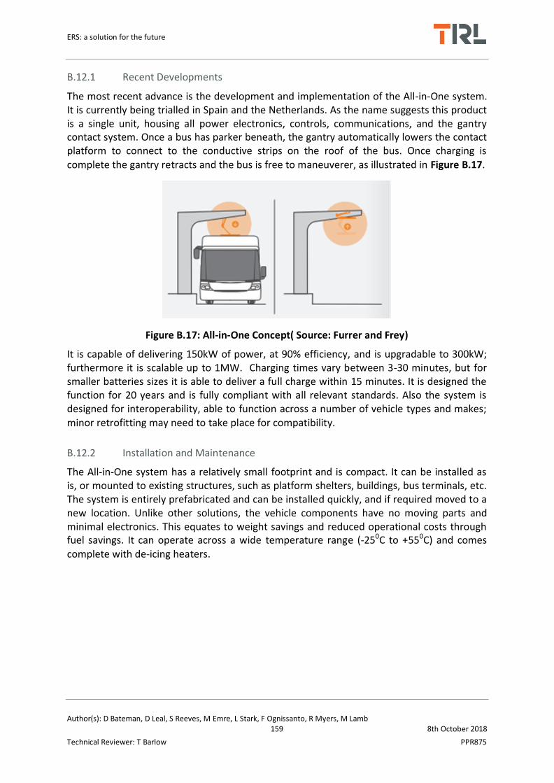
ERS: a solution for the future
Author(s): D Bateman, D Leal, S Reeves, M Emre, L Stark, F Ognissanto, R Myers, M Lamb 159 8th October 2018
Technical Reviewer: T Barlow PPR875
B.12.1 Recent Developments
The most recent advance is the development and implementation of the All-in-One system. It is currently being trialled in Spain and the Netherlands. As the name suggests this product is a single unit, housing all power electronics, controls, communications, and the gantry contact system. Once a bus has parker beneath, the gantry automatically lowers the contact platform to connect to the conductive strips on the roof of the bus. Once charging is
complete the gantry retracts and the bus is free to maneuverer, as illustrated in Figure B.17.
Figure B.17: All-in-One Concept( Source: Furrer and Frey)
It is capable of delivering 150kW of power, at 90% efficiency, and is upgradable to 300kW; furthermore it is scalable up to 1MW. Charging times vary between 3-30 minutes, but for smaller batteries sizes it is able to deliver a full charge within 15 minutes. It is designed the function for 20 years and is fully compliant with all relevant standards. Also the system is designed for interoperability, able to function across a number of vehicle types and makes; minor retrofitting may need to take place for compatibility.
B.12.2 Installation and Maintenance
The All-in-One system has a relatively small footprint and is compact. It can be installed as is, or mounted to existing structures, such as platform shelters, buildings, bus terminals, etc. The system is entirely prefabricated and can be installed quickly, and if required moved to a new location. Unlike other solutions, the vehicle components have no moving parts and minimal electronics. This equates to weight savings and reduced operational costs through fuel savings. It can operate across a wide temperature range (-250C to +550C) and comes complete with de-icing heaters.
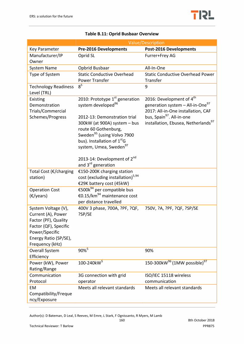
ERS: a solution for the future
Author(s): D Bateman, D Leal, S Reeves, M Emre, L Stark, F Ognissanto, R Myers, M Lamb 160 8th October 2018
Technical Reviewer: T Barlow PPR875
Table B.11: Oprid Busbaar Overview
Value/Description
Key Parameter Pre-2016 Developments Post-2016 Developments
Manufacturer/IP Owner
Oprid SL Furrer+Frey AG
System Name Opbrid Busbaar All-In-One
Type of System Static Conductive Overhead Power Transfer
Static Conductive Overhead Power Transfer
Technology Readiness Level (TRL)
85 9
Existing Demonstration Trials/Commercial Schemes/Progress
2010: Prototype 1st generation system developed96
2012-13: Demonstration trial 300kW (at 900A) system – bus route 60 Gothenburg, Sweden95 (using Volvo 7900 bus). Installation of 1stG system, Umea, Sweden97 2013-14: Development of 2nd and 3rd generation
2016: Development of 4th generation system – All-in-One97
2017: All-in-One installation, CAF bus, Spain97. All-in-one installation, Ebusea, Netherlands97
Total Cost (€/charging station)
€150-200K charging station cost (excluding installation)5,94
€29K battery cost (45kW)
Operation Cost (€/years)
€500k94 per compatible bus
€0.15/km94 maintenance cost per distance travelled
System Voltage (V), Current (A), Power Factor (PF), Quality Factor (QF), Specific Power/Specific Energy Ratio (SP/SE), Frequency (kHz)
400V 3 phase, 700A, ?PF, ?QF, ?SP/SE
750V, ?A, ?PF, ?QF, ?SP/SE
Overall System Efficiency
90%5 90%
Power (kW), Power Rating/Range
100-240kW5
150-300kW96 (1MW possible)97
Communication Protocol
3G connection with grid operator
ISO/IEC 15118 wireless communication
EM Compatibility/Frequency/Exposure
Meets all relevant standards Meets all relevant standards

ERS: a solution for the future
Author(s): D Bateman, D Leal, S Reeves, M Emre, L Stark, F Ognissanto, R Myers, M Lamb 161 8th October 2018
Technical Reviewer: T Barlow PPR875
System Maintenance Requirements
Routine Maintenance (if required), Annual safety inspections
Routine Maintenance (if required), Annual safety inspections
Estimated System Lifetime
30 years5,94
10 years (based 100 charge cycles per day)96
20 years (based on 1 million charge cycles)97
System Details( inroad, on-vehicle, roadside)
Roadside: Overhead rail extends over bus once in position On-Vehicle: extendable pantograph connects to overhead rail.
Roadside: Overhead unit (includes all power electronics) with 4 point pantograph On-Vehicle: Conductive contact strips on vehicle roof, on-board electronics, and battery, motor.
Operational Tolerances (temperature, pressure, vibration)
Temperature: -250C to +550C5
Temperature: -250C to +550C96
Effective Misalignment (xyz)
x = 0.5m x = 0.5m

ERS: a solution for the future
Author(s): D Bateman, D Leal, S Reeves, M Emre, L Stark, F Ognissanto, R Myers, M Lamb 162 8th October 2018
Technical Reviewer: T Barlow PPR875
B.13 WAVE IPT – Utah State University
Wireless Advanced Vehicle Electrification Inductive Power Transfer Inc (WAVE IPT) is a Utah State University spin-off company, founded in 2010, providing static wireless power transfer solutions for electric vehicles. To date the company have a commercially available system that can transfer 50kW of power over a 15-25cm air gap at efficiencies greater than 90%. Similar to other inductive solutions, IPT utilises electromagnetic coupling between two coils; one embedded in the pavement (at a bus stop or depot), and a secondary pick-up coil mounted to the underside of the vehicle. The company have a number of commercial operators using their technology for bus schemes across California, Texas, and Utah, USA. Similar to other manufacturers, WAVE hav adopted a modular design to accommodate varying power levels, in multiples of 50kW. Recently they have announced the launch of a bus scheme that uses stacked systems to provide 250kW of power. Literature indicates that this system costs approximately €575k to purchase a 100kW installation, including vehicle equipment; an additional €430k is required for construction, labour and grid connections. Reports indicate a 70% annual fuel saving compared to diesel; a saving of €26k a year per 80,500km/year. Current bus schemes are expanding due to successful trials, with 17 new charging stations being installed in California. The system meets all relevant standards for safety and electromagnetic exposure. It takes approximately 1 month to install and commission a charging station, with extensive excavation works required, seen in Figure B.18.
Table B.12 summarises the recent developments of the WAVE IPT.
Figure B.18: WAVE IPT Installation (Source: Wave IPT)

ERS: a solution for the future
Author(s): D Bateman, D Leal, S Reeves, M Emre, L Stark, F Ognissanto, R Myers, M Lamb 163 8th October 2018
Technical Reviewer: T Barlow PPR875
Table B.12: WAVE IPT Overview
Value/Description
Key Parameter Pre-2016 Developments Post-2016 Developments
Manufacturer/IP Owner WAVE WAVE
System Name IPT IPT
Type of System Static Wireless Power Transfer Static Wireless Power Transfer
Technology Readiness Level (TRL)
TRL 8-9 TRL 9
Existing Demonstration Trials/Commercial Schemes/Progress
2011-13: Development of WAVE IPT 1st generation solid state system5 2014: Commercial Operation at Utah State University Campus (USA) Bus 50kW installation, 1.6 miles long (140mile/day) 2014-15: Monterey, California, 50kW 4.5 mile long commercial bus operation. 2 x 50kW commercial operation Antelope Valley, California
2016: Commercial Operation of 10 electric bus using 50kW chargers. 8.6 mile route Long Beach, California98
City of McAllen, USA, 2 50kW electric bus commercial operation 2017: Announcement of 250kW commercial bus scheme for Antelope Valley Transit Authority, California. Commissioned to build 17 additional IPT charging stations over next two years104
Total Cost (€/lkm) €575k ($670k) for two 50kW in-road charging units and on-vehicle systems102, €430k ($500k) additional construction costs102,105
$600k per Electric Bus with systems using 50kW IPT99
Operation Cost (€/years) 70% fuel saving compared to diesel103
Annual $30K fuel saving (over 50k miles/year) compared to diesel99
System Voltage (V), Current (A), Power Factor (PF), Quality Factor (QF), Specific Power/Specific Energy Ratio (SP/SE), Frequency (kHz)
480V AC 3 phase (input) 330-390V DC (output), 23.4kHz
480V AC 3 phase (input) 330-390V DC (output), 23.4kHz
Overall System Efficiency 90%5 >90%
Power (kW), Power Rating/Range
5kW ,25kW, and 50kW 50kW (250kW prototype in development for commercial application)98

ERS: a solution for the future
Author(s): D Bateman, D Leal, S Reeves, M Emre, L Stark, F Ognissanto, R Myers, M Lamb 164 8th October 2018
Technical Reviewer: T Barlow PPR875
Air Gap (cm) 17.5cm5 15-25cm106
Communication Protocol Unknown Unknown
EM Compatibility/Frequency/Exposure
Meets all relevant standards Meets all relevant standards (Underwriters Laboratory Field Evaluation Certified)101
Installation Description (method, time, cost)
1 month installation time per charging in-road unit100

ERS: a solution for the future
Author(s): D Bateman, D Leal, S Reeves, M Emre, L Stark, F Ognissanto, R Myers, M Lamb 165 8th October 2018
Technical Reviewer: T Barlow PPR875
B.14 INTIS Integrated Infrastructure Solutions
INTIS is a German energy systems manufacturer, founded in 2011, and a subsidiary of IAB GmbH. They have produced a number of systems of varying power levels for static and dynamic wireless vehicle charging, ranging from 11-30kW; a 60kW prototype is currently under development. The system uses electromagnetic coupling of two coils, one placed on/in the ground, and the secondary pick-up placed on the vehicles underside. Current systems have validated overall efficiencies between 88-93%. Systems have been developed for light duty and passenger vehicles; their primary market is for industrial applications, such as forklifts, trolleys, and small plant. Dynamic charging has been tested, under laboratory conditions, for 30-60kW systems, where coils are placed sequentially to provide continuous power. Tests have been carried out for an 18m long Autotram electric bus and Artega electric car. For static charging installation the system takes approximately two weeks to install. Once installed, the system is completely automated, requiring little intervention from the vehicle user. The company have delivered systems which have been in use for some time, for small passenger cars, vans, and light plant, as illustrated in Figure B.19. Accelerated pavement testing has also been carried out to examine the effects of the system under representative traffic loads, and its effects on the surrounding pavement. For a brief overview please refer to Table B.13.
Figure B.19: INTIS wireless power transfer (Source: INTIS)
Table B.13: INTIS Overview
Value/Description
Key Parameter Pre-2016 Developments Post-2016 Developments
Manufacturer/IP Owner INTIS INTIS
System Name INTIS INTIS
Type of System Static/Dynamic Wireless Power Transfer
Static/Dynamic Wireless Power Transfer
Technology Readiness Level (TRL)
7 9
Existing Demonstration 2013-15: R&D prototype 2016: 30kW stationairy charger

ERS: a solution for the future
Author(s): D Bateman, D Leal, S Reeves, M Emre, L Stark, F Ognissanto, R Myers, M Lamb 166 8th October 2018
Technical Reviewer: T Barlow PPR875
Trials/Commercial Schemes/Progress
30kW Dynamic system for Artega sports car107. Autotram 60kW prototype for dynamic charging. VW T5 minivan 30kW system for stationary charging.
for Nissan Leaf Gen. 1 for stationary charging. 30kW charger for Citreo Berlingo Gen. 2 for stationary charging. 30kW charger for Nissan Leaf Gen. 2 for stationary charging 2017: 12KW charger developed for IVECO Daily van. 15kW system for Linde P250 luggage hauler for stationary charging 2018: 11kW charger for BMW i3 for stationary charging. All suitable for CHAdeMo DC charging applications
System Voltage (V), Current (A), Power Factor (PF), Quality Factor (QF), Specific Power/Specific Energy Ratio (SP/SE), Frequency (kHz)
350-600V AC three phase, 2-36kWh gross battery capacity
80-360V, 35-90kHz, 30-63kWh gross battery capacity110
Overall System Efficiency 88-93%107
Power (kW), Power Rating/Range
30-60kW 11-30kW108, 60kW107 (prototype under development)
Air Gap (cm) 10-15cm107 10-15cm107,108
EM Compatibility/Frequency/Exposure
Meets all relevant standards (compliant with ICNIRP 2010)
Installation Description (method, time, cost)
30kW system takes approximately 2 weeks to install in the road109
-
System Details( inroad, on-vehicle, roadside)
In-Road: - On-Vehicle: Pick-up unit 2000x800x22mm
In-Road: Copper coil (2000x800mm), 150kg per 20m segment107 On-vehicle: pick-up unit 880x860x25mm108

ERS: a solution for the future
Author(s): D Bateman, D Leal, S Reeves, M Emre, L Stark, F Ognissanto, R Myers, M Lamb 167 8th October 2018
Technical Reviewer: T Barlow PPR875
B.15 ElonRoad/Lund University
ElonRoad AB is a research organisation that has developed, in partnership with Lund Univesity, a conductive rail solution for dynamic vehicle charging. A rail consisting of short grounded segments arranged along a single track. Every other segment is switched on only when a car passes over it. Once an electrified segment is sensed, three pick-ups (inverted pantographs) extend from the vehicle underside to make contact with the rail to draw power. Once the car has passed over the section the rail is automatically swithed off and the pick-ups connect with the next section. The current system is mounted (by bolts and bitumen adhesive) on top of the road surface (essentially creating a longitudinal speed bump in the centre of the carriageway). The system is capable of delivering 240kW of power, and is being developed on a 210m purpose built test track in Lund, Sweden. The system has been developed for use with a Nissan Leaf. While it is capable of delivering a large power supply it is designed for lower speeds in an urban setting. As the system is mounted ontop of the road surface, water is able to flow betwwen the base of the system and the road. In cases of winter maintenance, a prototype snow plough has been developed and tested. It should be noted that the system has a grounded strip which prevents current
from leaking from any charged sections. The rail is approximately 5cm high at its peak.
Table B.14: ElonRoad Overview
Key Parameter Recent Development
Manufacturer/IP Owner ElonRoad/Lund University
System Name ElonRoad
Type of System Conductive Dynamic Rail
Technology Readiness Level (TRL) TRL 5-6111
Existing Demonstration Trials/Commercial Schemes/Progress
210m test track – Lund, Sweden
Total Cost (€/lkm) €600k/km112 - €1.5m/km113
€5K (pick-up for trucks) €2k (pick-up for cars)113
System Voltage (V), Current (A), Power Factor (PF), Quality Factor (QF), Specific Power/Specific Energy Ratio (SP/SE), Frequency (kHz)
600V AC, 300A,
Overall System Efficiency 90%113 (dynamic), 97%112 (static)
Power (kW), Power Rating/Range 240kW112 (static)
Communication Protocol Radio frequency identification (RFID)
EM Compatibility/Frequency/Exposure
Expected to meet all relevant safety standards.
Maximum Vehicle Speed (km/h) 90km/h tested
Estimated System Lifetime 10 years113
System Details( inroad, on-vehicle, roadside)
On-Road: Rail = 1000x300x50mm, 40kg (rail = 7kg, casing + cabling = 33kg)125

ERS: a solution for the future
Author(s): D Bateman, D Leal, S Reeves, M Emre, L Stark, F Ognissanto, R Myers, M Lamb 168 8th October 2018
Technical Reviewer: T Barlow PPR875
Operational Tolerances (temperature, load)
50kN max load125
Foreign Object Detection unknown
Effective Misalignment (xyz) 50-400mm126
(a)
(b)
(c)
Figure B.20. ElonRoad system (Source:ElonRoad)

ERS: a solution for the future
Author(s): D Bateman, D Leal, S Reeves, M Emre, L Stark, F Ognissanto, R Myers, M Lamb 169 8th October 2018
Technical Reviewer: T Barlow PPR875
B.16 Momentum Dynamics Corp.
Momentum Dynamics Corporation was founded in 2009, and has developed a number of high power static inductive charging solutions for shuttles and buses. More recently the company have been developing a concept for dynamic inductive charging. They have a number of commercially available products, all of which utilise magnetic coupling and near field communications. The system primary coils are embedded in the pavement, with the secondary coils located beneath the vehicles underside. Please refer to Table B.15 for a brief overview of developments.
Table B.15: Momentum Dynamics Corp Overview
Key Parameter Recent Developments
Manufacturer/IP Owner Momentum Dynamics Corporation
System Name Momentum Charger
Type of System Inductive Static (Dynamic under testing)
Technology Readiness Level (TRL)
TRL9 (static) TRL3-4 (dynamic)
Existing Demonstration Trials/Commercial Schemes/Progress
2017: Pilot operation of Link Transit 50kW (Maryland, USA) for BYD K9S bus. 2018:
Commercial operation of Link Transit 200kW (Washington, USA) for BYD K9S bus. Delivers 3.4kWh/minute. Operating 11-24km route, running 193-240km per day.
Commercial operation of 200kW bus scheme (Tennesse, USA)
Commercial operation of Link Transit 200kW (Maryland, USA) for BYD K9S bus. 3 Buses
Development of 400kW system
Estimated Total Cost (€) €214k per 200kW122
€3.16m for 3 x 200kW buses + systems & infrastructure (€115k per 200kW unit)123
Operation Cost (€/years) €3000/year (based on 2530kW per month at €0.1/kWh)124
System Voltage (V), Current (A), Power Factor (PF, Frequency (kHz)
400-480V AC (three phase), 120A, >0.99 PF, 85kHz121
Air Gap (cm) 30cm121
Overall System Efficiency 95%121
Power (kW), Power Rating/Range
50-75kW (modular design upto 300+kW)
Communication Protocol Node-2-node near field low latency comms
EM Safety UL, CE, FCC, IEEE C95.1, ICNIRP121
Estimated System Lifetime 2 year warranty121
Operational Tolerances (temperature, pressure,
-25oC to +60oC121

ERS: a solution for the future
Author(s): D Bateman, D Leal, S Reeves, M Emre, L Stark, F Ognissanto, R Myers, M Lamb 170 8th October 2018
Technical Reviewer: T Barlow PPR875
vibration)
Foreign Object Detection Yes (with living object protection option available)121
Effective Misalignment (xyz) x/y = 20cm121
Figure B.21. Momentum Dynamics system (Source: Momentum Dynamics)
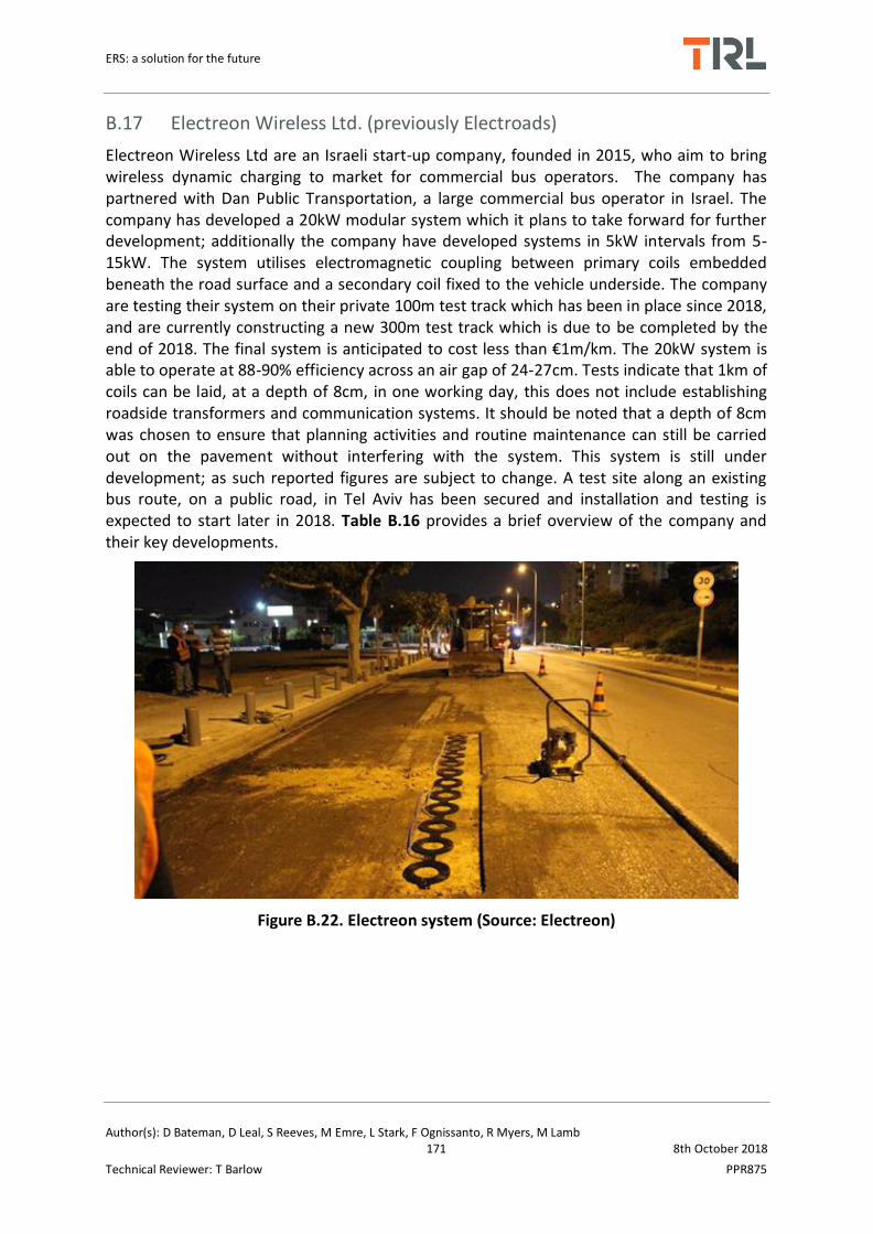
ERS: a solution for the future
Author(s): D Bateman, D Leal, S Reeves, M Emre, L Stark, F Ognissanto, R Myers, M Lamb 171 8th October 2018
Technical Reviewer: T Barlow PPR875
B.17 Electreon Wireless Ltd. (previously Electroads)
Electreon Wireless Ltd are an Israeli start-up company, founded in 2015, who aim to bring wireless dynamic charging to market for commercial bus operators. The company has partnered with Dan Public Transportation, a large commercial bus operator in Israel. The company has developed a 20kW modular system which it plans to take forward for further development; additionally the company have developed systems in 5kW intervals from 5-15kW. The system utilises electromagnetic coupling between primary coils embedded beneath the road surface and a secondary coil fixed to the vehicle underside. The company are testing their system on their private 100m test track which has been in place since 2018, and are currently constructing a new 300m test track which is due to be completed by the end of 2018. The final system is anticipated to cost less than €1m/km. The 20kW system is able to operate at 88-90% efficiency across an air gap of 24-27cm. Tests indicate that 1km of coils can be laid, at a depth of 8cm, in one working day, this does not include establishing roadside transformers and communication systems. It should be noted that a depth of 8cm was chosen to ensure that planning activities and routine maintenance can still be carried out on the pavement without interfering with the system. This system is still under development; as such reported figures are subject to change. A test site along an existing bus route, on a public road, in Tel Aviv has been secured and installation and testing is expected to start later in 2018. Table B.16 provides a brief overview of the company and their key developments.
Figure B.22. Electreon system (Source: Electreon)

ERS: a solution for the future
Author(s): D Bateman, D Leal, S Reeves, M Emre, L Stark, F Ognissanto, R Myers, M Lamb 172 8th October 2018
Technical Reviewer: T Barlow PPR875
Table B.16: Electreon Overview
Key Parameter Recent Developments
Manufacturer/IP Owner Electreon
System Name Electreon
Type of System Inductive Dynamic
Technology Readiness Level (TRL)
TRL5-6
Existing Demonstration Trials/Commercial Schemes/Progress
2016: Developed 100m test track 2018:
Tel Aviv pilot demonstration planned Development of new 300m test track, Tel Aviv
Air Gap (cm) 24-27cm
Overall System Efficiency 88-90%
Power (kW), Power Rating/Range
5-20kW (5-15kW in 5kW intervals, 20kW standalone system)
Communication Protocol Unique real-time communications
EM Safety Working towards ICNIRP standards for Em safety
Estimated System Lifetime Unknown, estimated maintenance period 5 years for roadside equipment

ERS: a solution for the future
Author(s): D Bateman, D Leal, S Reeves, M Emre, L Stark, F Ognissanto, R Myers, M Lamb 173 8th October 2018
Technical Reviewer: T Barlow PPR875
B.18 Honda R&D Co.
Honda R&D has been developing their conductive rail dynamic charging solution since 2014. This system is different from alternative conductive dynamic systems in that the pantograph extents from the vehicles side sill; extending horizontally. The collection unit then connects to the conductive rails which are retrofitted to a vehicle restraint system at the roadside (galvanised steel crash barrier). Since its developments Honda has demonstrated 4 prototypes which have been subject to extensive track testing and simulation modelling. The most current prototype is capable of delivering 450kW (input) and 375kW (vehicle output) and has been track tested up to 150km/h.
The system uses a mixture of manual and automatic control features. Firstly the vehicle must enter the dynamic charging lane. After which the vehicle operator manually switches on the collection unit, putting it in a ready state. The collection unit then makes contact with the conductive rail, with the vehicle automatically detecting this connection. It then transitions to a power supply/charging sequence. Charging is controlled by the vehicles on-board integrated ECU, to realise a set current, power and voltage, whilst also monitoring and controlling the vehicles battery capacity, power levels, and system temperature. Once charging is complete the collection unit retracts and fits back into the vehicles side sill. The guide plates fitted around each terminal on the rail ensure a constant, but not fixed, connection. The collection unit has damper and flexion mechanisms to absorb horizontal and vertical deflections whilst in contact with the rail. The vehicle is still able to automatically terminate charging and retract the collection unit should the driver need to perform evasive/overtaking manoeuvres, or leave the charging lane at will.
The collection unit is capable of delivering power across a horizontal range of upto 1.3m between the vehicle and the conductive rail. Early research indicates that the cost of the system is potentially substantially cheaper than alternatives. As the system is under development cost data is not available; however it is estimated to have an installation cost 1/20th the price of rival inductive systems. The developers note these cost saving are a consequence of simplifying on-road equipment, eliminating control The developers also note that testing has proved that 1km of charging infrastructure provides 25km of range for the vehicle. An overview of developments is provided in Table B.17 and images of the system are given in
Table B.17: Honda R&D Overview
Value/Description
Key Parameter Pre-2016 Developments Post-2016 Developments
Manufacturer/IP Owner Honda R&D Co. Honda R&D Co.
System Name High Power Dynamic Charging System
High Power Dynamic Charging System
Type of System Conductive Rail Dynamic Conductive Rail Dynamic
Technology Readiness Level (TRL)
TRL3-4 TRL5-6
Existing Demonstration Trials/Commercial Schemes/Progress
2014/15: Development and testing of Prototype-0 and Prototype-1.
2017: Track testing of 180kW up to 156km/h whilst charging129.

ERS: a solution for the future
Author(s): D Bateman, D Leal, S Reeves, M Emre, L Stark, F Ognissanto, R Myers, M Lamb 174 8th October 2018
Technical Reviewer: T Barlow PPR875
Laboratory and track trial for long-run (2 hour) testing on a range of vehicle speeds from 7-100km/h – Honda Test Track, Japan128.
Development of 450kW system with the aim of charging upto 200km/h129. Development of Prototype-3129,
130
System Voltage (V), Current (A)
375V DC (input) 500V DC (output), 300A128
800V DC (input) 750V DC (output), 600A130
Overall System Efficiency N/A >95%
Power (kW), Power Rating/Range
150kW (130kW max vehicle output)128
450kW130 (375kW max vehicle output)130
Vehicle Speed (km/h) 7-100km/h128 up to 150km/h130
Cots (€/l.km) Installation cost estimated at 1/20th the cost of inductive dynamic systems128, 129.
Unchanged, limited information available
Installation Description (method, time, cost)
The conductive rails are retrofitted to existing vehicle restraint systems (steel crash guard), which is connected via cabling to a high capacity storage battery located at the roadside – for track demonstrations only. The final version will still utilise a conductive rail connected to the lower portion of a vehicle restraint system
unchanged
System Details( inroad, on-vehicle, roadside)
On-Vehicle: Power collection unit (essentially a lateral pantograph, extending from the vehicles side horizontally). Collection unit made from 5 core components: support section (contact point for vehicle), arm, head (consisting of rotating roller with positive/negative terminals) connecting to the conductive rail terminals, damper and electric linear actuator. Charging converter; ECU; super quick charging battery/capacitor; DC/DC inverter; motor; and integrated ECU.
All components (remain the same as previously) On-Vehicle: charging converter made from relays, power elements, reactors, condensers, a water-cooling system and control circuits129. Vehicle battery unit made from high rate, quick charging lithium-ion. Integrated ECU monitors power and temperature of the battery and controls charging129.

ERS: a solution for the future
Author(s): D Bateman, D Leal, S Reeves, M Emre, L Stark, F Ognissanto, R Myers, M Lamb 175 8th October 2018
Technical Reviewer: T Barlow PPR875
Roadside: High capacity storage battery (large container placed at roadside); Conductive rails fitted to typical vehicle restraint system base via an insulator, coupler, with guide plates (one for each +ve/-ve terminal) arranged in a V shape. The area around the conductive rails is fitted with protective covering128. No elements are embedded within the road. All infrastructure is on-board the vehicle or at the roadside.
Figure B.23. Honda R&D conductive rail concept
© Honda R&D Ltd (2018)

ERS: a solution for the future
Author(s): D Bateman, D Leal, S Reeves, M Emre, L Stark, F Ognissanto, R Myers, M Lamb 176 8th October 2018
Technical Reviewer: T Barlow PPR875
Appendix C ERS Risk Assessment
Below are a series of risk assessment as described in brief in the main body of the report. Risk assessments have been conducted for:
Plug-in charging systems
Inductive stationary systems
Inductive ERS
Conductive overhead ERS
Conductive Rail ERS

ERS: a solution for the future
Author(s): D Bateman, D Leal, S Reeves, M Emre, L Stark, F Ognissanto, R Myers, M Lamb 177 8th October 2018
Technical Reviewer: T Barlow PPR875
C.1 Plug-in charging system
C.1.1 Installation
Hazard Hazardous event Persons affected
Potential mitigations Level of Concern
Tolerability of risk discussion
Installation of plug in charging system
Operative struck by road user
Operative, ORU
Installations of plug in charging system by competent persons in appropriate locations
Very low Plug in charging systems are likely to be installed in car parks or minor roads, where risks to workers from moving vehicles are lower.
Controls for the installation of plug-in charging technology already exist due to this technology being in existence for the past decade.
Existing electrical systems cannot cope with additional load
Operative, Plug in vehicle user
Existing regulations/standards for electrical work
Very low Extensive controls for making changes to electrical systems already exist
Working with electrical equipment
Electrical shock during installation
Operative, Plug in vehicle user
Safe systems of work to be in place, task related risk assessments carried out to ensure risk is reduced to as low as reasonably practicable.
Installations to be conducted by a competent
person
Low Extensive controls for working with electrical equipment already exist

ERS: a solution for the future
Author(s): D Bateman, D Leal, S Reeves, M Emre, L Stark, F Ognissanto, R Myers, M Lamb 178 8th October 2018
Technical Reviewer: T Barlow PPR875
C.1.2 Use
Hazard Hazardous event Persons affected Potential mitigations Level of Concern
Tolerability of risk discussion
Electromagnetic emission
Interference with pacemakers/impact on health
Plug in vehicle user, ORU
Guidance from health professionals. Ensure emissions contained within charging system (shielding)
Very low Emissions from charging systems are likely to be so low that the level of risk is negligible.
Interference with radio waves/mobile signals
Plug in vehicle user, ORU
Ensure emissions contained within charging system (shielding)
Very Low
Location of plug in charging system
Collision with charging system Plug in vehicle user, ORU
Site assessments should be conducted to ensure charging system is installed at a suitable location
Low Risks associated with installing street furniture and parking are already well understood and controlled
Collision with ORU Plug in vehicle user , ORU
Site assessments should be conducted to ensure charging system is installed at a suitable location
Low

ERS: a solution for the future
Author(s): D Bateman, D Leal, S Reeves, M Emre, L Stark, F Ognissanto, R Myers, M Lamb 179 8th October 2018
Technical Reviewer: T Barlow PPR875
Electrical safety Fire ORU, emergency services, operatives, pedestrians, maintenance crews, local residents
Risk of fire is managed through design and installation process. Existing automotive safety practices should be applied. Existing electrical safety standards and building regulations.
Low Controls for the safety of plug-in charging technology already exist due to this technology being in existence for the past decade. The current level of risk posed is considered to be tolerable.
Burn ORU, general public Provision for system to be switched off and/or isolated in the event of an emergency. System can cut out in the event of an overload. Compliance with electrical standards
Low
Electric shock - user while charging
Plug in vehicle user, ORU
Provision for system to be switched off and/or isolated in the event of an emergency
Low
Electric shock - misappropriation/illegal activity
Plug in vehicle user, ORU
The provision of secure locations and additional warning signs
Low Charging systems are typically installed in public spaces and the power supply system is often buried under the road surface making this hazardous event an unlikely occurrence.

ERS: a solution for the future
Author(s): D Bateman, D Leal, S Reeves, M Emre, L Stark, F Ognissanto, R Myers, M Lamb 180 8th October 2018
Technical Reviewer: T Barlow PPR875
C.1.3 Maintenance (routine or emergency)
Hazard Hazardous event Persons affected Potential mitigations Level of Concern Tolerability of risk discussion
Maintaining equipment
Operative(s) struck by road user
Operatives Safe systems of work to be in place, additional, task related risk assessments carried out to ensure risk is reduced to as low as reasonably practicable.
Maintenance to be
conducted by a
competent person.
Low Controls for the maintenance of
plug-in charging technology
already exist due to this technology
being in existence for the past
decade.
If maintenance is conducted at
appropriate intervals by competent
persons, the level of risk posed is
likely to be tolerable.
Poor quality installation leads to quicker failures
ORU Low
Electric shock from contact with equipment whilst it is live
Operatives Low
Equipment inaccessible Operatives Low
Operative(s) injured by equipment
Operatives Low

ERS: a solution for the future
Author(s): D Bateman, D Leal, S Reeves, M Emre, L Stark, F Ognissanto, R Myers, M Lamb 181 8th October 2018
Technical Reviewer: T Barlow PPR875
C.1.4 Removal/replacing/decommissioning
Hazard Hazardous event
Persons affected
Potential mitigations Level of Concern
Tolerability of risk discussion
Removing/replacing /decommissioning system
Operative struck by road user
Operatives Implementation of temporary traffic management in line with relevant guidance, as appropriate
Low Equipment is likely to be in low speed, public spaces. Using TTM as appropriate will minimise the level of risk posed.
Sparking equipment Operative sustains burn
Operatives Removal and replacement of equipment to be conducted by a competent person
Very low If decommissioning and removal tasks are conducted by competent persons, in line with current best practice, the level of risk posed is likely to remain tolerable.
Working with electrical equipment
Electrical shock during installation
Operatives Low
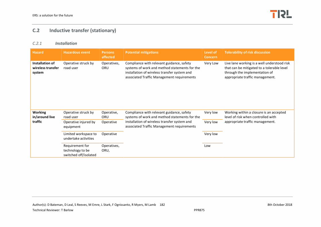
ERS: a solution for the future
Author(s): D Bateman, D Leal, S Reeves, M Emre, L Stark, F Ognissanto, R Myers, M Lamb 182 8th October 2018
Technical Reviewer: T Barlow PPR875
C.2 Inductive transfer (stationary)
C.2.1 Installation
Hazard Hazardous event Persons affected
Potential mitigations Level of Concern
Tolerability of risk discussion
Installation of wireless transfer system
Operative struck by road user
Operatives, ORU
Compliance with relevant guidance, safety systems of work and method statements for the installation of wireless transfer system and associated Traffic Management requirements
Very Low Live lane working is a well understood risk that can be mitigated to a tolerable level through the implementation of appropriate traffic management.
Working in/around live traffic
Operative struck by road user
Operative, ORU
Compliance with relevant guidance, safety systems of work and method statements for the installation of wireless transfer system and associated Traffic Management requirements
Very low Working within a closure is an accepted level of risk when controlled with appropriate traffic management. Operative injured by
equipment Operative Very low
Limited workspace to undertake activities
Operative Very low
Requirement for technology to be switched off/isolated
Operatives, ORU,
Low

ERS: a solution for the future
Author(s): D Bateman, D Leal, S Reeves, M Emre, L Stark, F Ognissanto, R Myers, M Lamb 183 8th October 2018
Technical Reviewer: T Barlow PPR875
C.2.2 Use
Hazard Hazardous event Persons affected Potential mitigations Level of Concern Tolerability of risk discussion
Electrocution Damaged system Operative, ORU, pedestrian
Appropriate maintenance schedule conducted by competent persons
Low If appropriate mitigations are in place and maintenance is conducted by competent persons, in line with relevant guidance, it is likely that the level of risk will be tolerable.
Misappropriation/illegal activity
ORU Provision of High Voltage warning signs Public awareness
Low It is likely that the power supply system will be buried under the road surface making this hazardous event an unlikely occurrence
Broken down ERS vehicle being recovered
Vehicle recovery organisations
Safe systems of work to be in place, additional, task related risk assessments carried out to ensure risk is reduced to as low as reasonably practicable
Low Recovery operators are already working with electric and hybrid vehicles. Any changes to vehicles to ensure compatibility with the charging system should be communicated to appropriate people to ensure the level of risk remains tolerable.
Electromagnetic emission
Interference with pacemakers/ Impact on health
Operatives, ORU, pedestrian, emergency services, vehicle recovery organisations
Guidance from health professionals. Ensure emissions contained within charging system (shielding)
Very Low Public awareness Guidance from health professionals and in line with the European Standard 45502-2-1.

ERS: a solution for the future
Author(s): D Bateman, D Leal, S Reeves, M Emre, L Stark, F Ognissanto, R Myers, M Lamb 184 8th October 2018
Technical Reviewer: T Barlow PPR875
Interference with road side signs
Operatives, ORU, pedestrian, emergency services, vehicle recovery organisations
Ensure emissions contained within charging system (shielding)
Low Ensure emissions are so low people are not adversely affected and that the risk remains tolerable.
Interference with emergency response equipment
Operatives, emergency services, vehicle recovery organisations
Low
Interference with in-car equipment
Operatives, ORU, pedestrian, emergency services, vehicle recovery organisations
Low
Interference with radio waves/mobile signals
Operatives, ORU, pedestrian, emergency services, vehicle recovery organisations
Low
Electrical disturbances for nearby residences/businesses
Pedestrian Low
Collision
Collision with wireless charging roadside equipment
ORU, pedestrians, emergency services,
Provision for system to be switched off and/or isolated in the event of an emergency.
Ensure equipment is
installed in an appropriate,
safe location.
Medium If equipment is installed in an appropriate location the probability of a collision occurring will be minimised.
Collision causes ORU vehicle fire
ORU Very Low

ERS: a solution for the future
Author(s): D Bateman, D Leal, S Reeves, M Emre, L Stark, F Ognissanto, R Myers, M Lamb 185 8th October 2018
Technical Reviewer: T Barlow PPR875
Collision between ORU and stationary vehicle
ORU
Low
Electrical safety Fire in vehicle or equipment ORU, pedestrians, emergency services, Operatives
Inspection regime of equipment
Provision for system to be
switched off and/or
isolated in the event of an
emergency. Equipment
should comply with
relevant electrical safety
standards.
Low The system design needs to be compliant with electrical safety design standards to ensure the risks are minimised and remain tolerable.
Safety of vehicle occupants from electrical equipment in the event of an incident e.g. flooding
ORU, pedestrians, emergency services, Operatives
Low
ERS equipment embedded in the road surface
Substandard road surface/skid resistance
Vehicle recovery organisations, ORU, pedestrians, emergency services, vulnerable ORUs
Equipment buried below the surface. Surface must have skid resistance at least as good as the existing infrastructure.
Medium It is likely that the level of risk posed can be minimised through appropriate design and materials.
Road surface damage leading to secondary incidents
Vehicle recovery organisations, ORU, pedestrians, emergency services, vulnerable ORUs
Ensure equipment does not impact the integrity of the road surface.
Medium

ERS: a solution for the future
Author(s): D Bateman, D Leal, S Reeves, M Emre, L Stark, F Ognissanto, R Myers, M Lamb 186 8th October 2018
Technical Reviewer: T Barlow PPR875
C.2.3 Maintenance (routine or emergency)
Hazard Hazardous event Persons affected Potential mitigations Level of Concern
Tolerability of risk discussion
Maintaining equipment in/near carriageway
Operative struck by road user Operatives Safe systems of work to be in place, additional, task related risk assessments carried out to ensure risk is reduced to as low as reasonably practicable. Use of traffic management in line with relevant standards.
Low Working in/near live traffic is a well-practiced area for road workers, it is important that the introduction of this technology does not increase the risk level.
Noise-damage to ears Operatives Low
General construction related injuries (HAV's, slips, trips and falls)
Operatives Low
Poor quality installation leads to quicker failures
ORU Low
Electrocution from contact with ERS equipment whilst it is live
Operatives Low
Equipment inaccessible Operatives Low
Operative injured by equipment
Operatives Low
Implications of burying primary systems under the road surface
Disruption from maintenance Operatives, ORU, emergency services
Ensure rigorous testing of equipment, monitoring procedures during trial phase.
Ensure equipment is sufficiently encased to minimise the impact of adverse
Low
Ensure equipment does not need maintaining more frequently than the road surface needs replacing.
Reliability of equipment/maintenance requirements
Operatives, ORU Low

ERS: a solution for the future
Author(s): D Bateman, D Leal, S Reeves, M Emre, L Stark, F Ognissanto, R Myers, M Lamb 187 8th October 2018
Technical Reviewer: T Barlow PPR875
Impact of adverse weather on system reliability and safety
Operatives, ORU weather or temperature variations. Low
C.2.4 Removal/replacing/ decommissioning
Hazard Hazardous event Persons affected Potential mitigations Level of Concern Tolerability of risk discussion
Removing/replacing/decommissioning system
Operative struck by road user
Operatives Removal and replacement of equipment to be conducted by a competent person. Ensure appropriate traffic management is in place. Ensure compliance with relevant standards and guidance.
Very low Consideration should also be given as to the environmental cost of removing a system (recyclable materials, safe disposal).
If tasks are conducted by a
competent person in line with
relevant safety standards and
guidance, the risk is likely to remain
tolerable.
Electric shock Operatives Low
Sparking equipment Operative sustains burn Operatives Very low

ERS: a solution for the future
Author(s): D Bateman, D Leal, S Reeves, M Emre, L Stark, F Ognissanto, R Myers, M Lamb 188 8th October 2018
Technical Reviewer: T Barlow PPR875
C.3 Wireless transfer (dynamic)
C.3.1 Installation
Hazard Hazardous event Persons affected
Potential mitigations Level of Concern
Tolerability of risk discussion
Installation and removal of temporary traffic management
Road worker struck by road user
Road workers, road user
Temporary Traffic Management (TTM) installed in line with relevant guidance
Very Low Live lane working and working within a closure is a well understood and managed risk that can be controlled through the implementation of appropriate traffic management in line with relevant guidance.
Working within the closure
Operative struck by road user
Operative, road user
Complex operation in limited space will require careful control.
Safe systems of work to be in place,
additional, task related risk
assessments carried out to ensure
risk is reduced to as low as
reasonably practicable
Very low
Operative injured by equipment
Operative Very low
Limited workspace to undertake activities
Operative Very low
Requirement for technology to be switched off/isolated
Operatives, road users,
Low
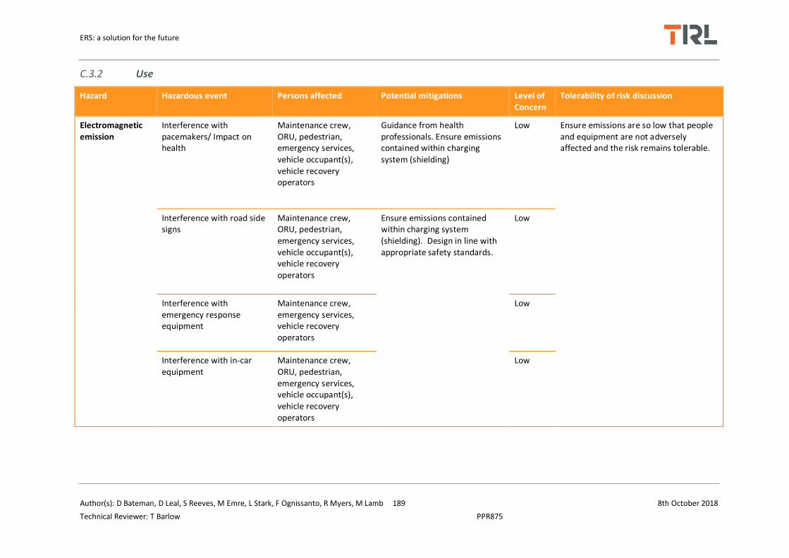
ERS: a solution for the future
Author(s): D Bateman, D Leal, S Reeves, M Emre, L Stark, F Ognissanto, R Myers, M Lamb 189 8th October 2018
Technical Reviewer: T Barlow PPR875
C.3.2 Use
Hazard Hazardous event Persons affected Potential mitigations Level of Concern
Tolerability of risk discussion
Electromagnetic emission
Interference with pacemakers/ Impact on health
Maintenance crew, ORU, pedestrian, emergency services, vehicle occupant(s), vehicle recovery operators
Guidance from health professionals. Ensure emissions contained within charging system (shielding)
Low Ensure emissions are so low that people and equipment are not adversely affected and the risk remains tolerable.
Interference with road side signs
Maintenance crew, ORU, pedestrian, emergency services, vehicle occupant(s), vehicle recovery operators
Ensure emissions contained within charging system (shielding). Design in line with appropriate safety standards.
Low
Interference with emergency response equipment
Maintenance crew, emergency services, vehicle recovery operators
Low
Interference with in-car equipment
Maintenance crew, ORU, pedestrian, emergency services, vehicle occupant(s), vehicle recovery operators
Low
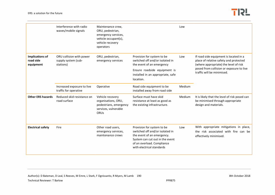
ERS: a solution for the future
Author(s): D Bateman, D Leal, S Reeves, M Emre, L Stark, F Ognissanto, R Myers, M Lamb 190 8th October 2018
Technical Reviewer: T Barlow PPR875
Interference with radio waves/mobile signals
Maintenance crew, ORU, pedestrian, emergency services, vehicle occupant(s), vehicle recovery operators
Low
Implications of road side equipment
ORU collision with power supply system (sub-stations)
ORU, pedestrian, emergency services
Provision for system to be switched off and/or isolated in the event of an emergency
Ensure roadside equipment is
installed in an appropriate, safe
location.
Low If road side equipment is located in a place of relative safety and protected (where appropriate) the level of risk posed from collision or exposure to live traffic will be minimised.
Increased exposure to live traffic for operative
Operative Road side equipment to be installed away from road side
Medium
Other ERS hazards Reduced skid resistance on road surface
Vehicle recovery organisations, ORU, pedestrians, emergency services, vulnerable ORUs
Surface must have skid resistance at least as good as the existing infrastructure.
Medium It is likely that the level of risk posed can be minimised through appropriate design and materials.
Electrical safety Fire Other road users, emergency services, maintenance crews
Provision for system to be switched off and/or isolated in the event of an emergency. System can cut out in the event of an overload. Compliance with electrical standards
Low With appropriate mitigations in place,
the risk associated with fire can be
effectively minimised.

ERS: a solution for the future
Author(s): D Bateman, D Leal, S Reeves, M Emre, L Stark, F Ognissanto, R Myers, M Lamb 191 8th October 2018
Technical Reviewer: T Barlow PPR875
Damaged system Operative, ORU, pedestrian
Appropriate maintenance schedule conducted by competent persons
Low The power supply system is often buried under the road surface making this hazardous event an unlikely occurrence
Misappropriation/illegal activity
ORU Provision of High Voltage warning signs Public awareness
Low
Broken down ERS vehicle being recovered
Vehicle recovery organisations
Safe systems of work to be in place, additional, task related risk assessments carried out to ensure risk is reduced to as low as reasonably practicable.
Low Recovery operators are already working
with electric and hybrid vehicles. Any
changes to vehicles to ensure
compatibility with the charging system
should be communicated to the relevant
persons to ensure risks are reduced to a
tolerable level.
Safety of vehicle occupants from electrical equipment
ORU Fully isolated equipment Low The level of risk posed is unlikely to be higher than the level of risk currently posed by electric vehicles.

ERS: a solution for the future
Author(s): D Bateman, D Leal, S Reeves, M Emre, L Stark, F Ognissanto, R Myers, M Lamb 192 8th October 2018
Technical Reviewer: T Barlow PPR875
C.3.3 Maintenance (routine or emergency)
Hazard Hazardous event Persons affected
Potential mitigations Level of Concern
Tolerability of risk discussion
Maintaining equipment in/near carriageway
Operative struck by road user
Operative Ensure equipment is installed in a suitable, safe location.
Ensure appropriate traffic management is in place. All maintenance should be conducted by a competent person and in line with electrical safety standards.
Low With appropriate controls in place this risk is likely to be adequately managed. However, significant maintenance requirements may increase road worker exposure to live traffic beyond an acceptable level.
Noise-damage to ears Operative Low
General construction related injuries (HAV's, slips, trips and falls)
Operative Low
Poor quality installation leads to quicker failures
ORU Low
Electrocution from contact with ERS equipment whilst it is live
Operative Low
Equipment inaccessible
Operative Low
Operative injured by equipment
Operative Low
Implications of burying primary systems under the road surface
Disruption from maintenance
Operative ORU, emergency services
Ensure rigorous testing of equipment, monitoring procedures during trial phase
Low Ensure equipment does not need maintaining more frequently than the road surface needs replacing to ensure risks are not increased beyond a tolerable level.
Impact of adverse weather on system reliability and safety
Operative, ORU
Ensure equipment is sufficiently encased to minimise the impact of adverse weather or temperature variations.
Medium

ERS: a solution for the future
Author(s): D Bateman, D Leal, S Reeves, M Emre, L Stark, F Ognissanto, R Myers, M Lamb 193 8th October 2018
Technical Reviewer: T Barlow PPR875
C.3.4 Removal/replacing/decommissioning
Hazard Hazardous event
Persons affected
Potential mitigations Level of Concern
Tolerability of risk discussion
Removing/replacing/decommissioning system
Operative struck by road user
Operative
Ensure appropriate traffic management is in place. Ensure compliance with relevant standards and guidance.
Very low
Consideration should also be given as to the environmental cost of removing a system (recyclable materials, safe disposal)
If tasks are conducted by a competent
person in line with relevant safety
standards and guidance, the risk is likely
to remain tolerable. Electric shock Operative Low
Sparking equipment Operative sustains burn
Operative Very low

ERS: a solution for the future
Author(s): D Bateman, D Leal, S Reeves, M Emre, L Stark, F Ognissanto, R Myers, M Lamb 194 8th October 2018
Technical Reviewer: T Barlow PPR875
C.4 Charging through overhead electrification
C.4.1 Installation
Hazard Hazardous event Persons affected Potential mitigations Level of Concern Tolerability of risk discussion
Installation and removal of temporary traffic management
Road worker struck by road user
Road workers, ORU, Traffic Officers
Installation and removal in line with appropriate guidance and best practice
Very Low Live lane working and working within a closure is a well understood and managed risk that can be controlled through the implementation of appropriate traffic management in line with relevant guidance.
Working within the closure
Operative struck by road user
Operative, ORU Safe systems of work to be in place, additional, task related risk assessments carried out to ensure risk is reduced to as low as reasonably practicable
Installation of
equipment to be
conducted by a
competent person
Very low
Operative injured by equipment
Operative Very low
Limited workspace to undertake activities
Operative Very low
Requirement for technology to be switched off/isolated
Operative, ORU Low
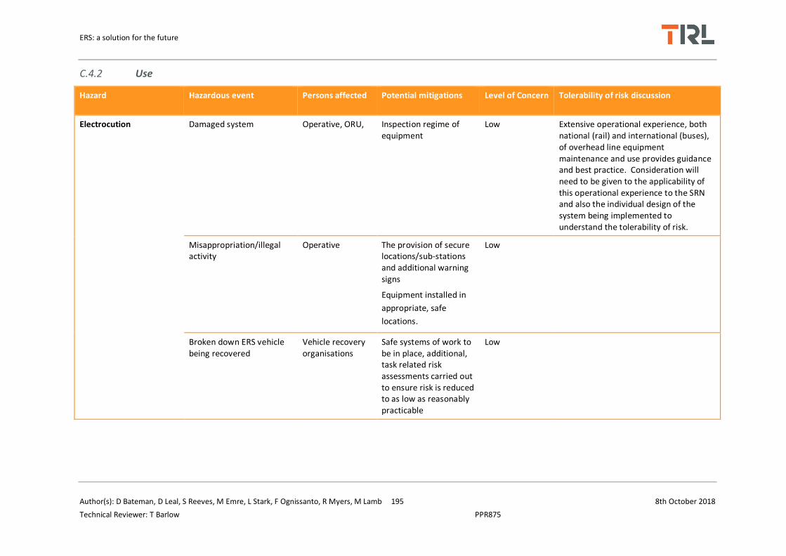
ERS: a solution for the future
Author(s): D Bateman, D Leal, S Reeves, M Emre, L Stark, F Ognissanto, R Myers, M Lamb 195 8th October 2018
Technical Reviewer: T Barlow PPR875
C.4.2 Use
Hazard Hazardous event Persons affected Potential mitigations Level of Concern Tolerability of risk discussion
Electrocution Damaged system Operative, ORU, Inspection regime of equipment
Low Extensive operational experience, both national (rail) and international (buses), of overhead line equipment maintenance and use provides guidance and best practice. Consideration will need to be given to the applicability of this operational experience to the SRN and also the individual design of the system being implemented to understand the tolerability of risk.
Misappropriation/illegal activity
Operative The provision of secure locations/sub-stations and additional warning signs
Equipment installed in
appropriate, safe
locations.
Low
Broken down ERS vehicle being recovered
Vehicle recovery organisations
Safe systems of work to be in place, additional, task related risk assessments carried out to ensure risk is reduced to as low as reasonably practicable
Low
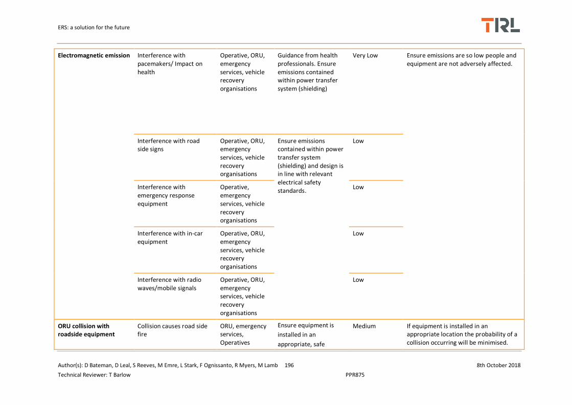
ERS: a solution for the future
Author(s): D Bateman, D Leal, S Reeves, M Emre, L Stark, F Ognissanto, R Myers, M Lamb 196 8th October 2018
Technical Reviewer: T Barlow PPR875
Electromagnetic emission Interference with pacemakers/ Impact on health
Operative, ORU, emergency services, vehicle recovery organisations
Guidance from health professionals. Ensure emissions contained within power transfer system (shielding)
Very Low Ensure emissions are so low people and equipment are not adversely affected.
Interference with road side signs
Operative, ORU, emergency services, vehicle recovery organisations
Ensure emissions contained within power transfer system (shielding) and design is in line with relevant electrical safety standards.
Low
Interference with emergency response equipment
Operative, emergency services, vehicle recovery organisations
Low
Interference with in-car equipment
Operative, ORU, emergency services, vehicle recovery organisations
Low
Interference with radio waves/mobile signals
Operative, ORU, emergency services, vehicle recovery organisations
Low
ORU collision with roadside equipment
Collision causes road side fire
ORU, emergency services, Operatives
Ensure equipment is
installed in an
appropriate, safe
Medium If equipment is installed in an appropriate location the probability of a collision occurring will be minimised.

ERS: a solution for the future
Author(s): D Bateman, D Leal, S Reeves, M Emre, L Stark, F Ognissanto, R Myers, M Lamb 197 8th October 2018
Technical Reviewer: T Barlow PPR875
location.
Collision causes ORU vehicle fire
ORU Ensure equipment is
installed in an
appropriate, safe
location.
Provision for system to be switched off and/or isolated in the event of an emergency.
Low
ERS vehicle collision with ORU
ORU does not hear ERS vehicle
ERS vehicle operator, ORU
Awareness campaign to highlight the introduction of the new technology and associated vehicles.
Low ERS vehicle should be independently assessed to ensure it remains as resilient in the event of a collision as other vehicles of its class.
May be distracting initially but unlikely
to pose a lasting threat
Other road user distraction ERS vehicle operator, ORU
Low
ORU does not see ERS vehicle
ERS vehicle operator, ORU
Low
ERS driver distraction ERS vehicle operator, ORU,
Medium
Rear-end collision ERS vehicle operator, ORU
Low
ERS vehicle breakdown/malfunction
Congestion build-up Vehicle recovery organisations, ORU
Safe systems of work to be in place, additional, task related risk
Low With appropriate mitigations and
awareness, the charging system should
not increase the level of risk to affected

ERS: a solution for the future
Author(s): D Bateman, D Leal, S Reeves, M Emre, L Stark, F Ognissanto, R Myers, M Lamb 198 8th October 2018
Technical Reviewer: T Barlow PPR875
Recovery operative struck by ORU
Vehicle recovery organisations
assessments carried out to ensure risk is reduced to as low as reasonably practicable
Low parties during vehicle breakdown or
malfunction.
Other ERS hazards Emergency helicopter unable to attend major incident/accident
Emergency services, ORU, operative, vehicle recovery organisations
Consultation with emergency services and relevant stakeholders
Medium It is important to ensure that emergency response plans are not disrupted and the level of risk to persons requiring emergency care remains tolerable.

ERS: a solution for the future
Author(s): D Bateman, D Leal, S Reeves, M Emre, L Stark, F Ognissanto, R Myers, M Lamb 199 8th October 2018
Technical Reviewer: T Barlow PPR875
C.4.3 Maintenance (routine or emergency)
Hazard Hazardous event Persons affected Potential mitigations Level of Concern
Tolerability of risk discussion
Maintaining equipment in/near carriageway
Operative struck by road user
Operatives Ensure equipment is installed in a suitable, safe location.
Ensure appropriate traffic
management is in place. All
maintenance should be conducted by
a competent person and in line with
electrical safety standards.
Low With appropriate controls in place this risk is likely to be adequately managed. However, significant maintenance requirements may increase road worker exposure to live traffic beyond an acceptable level.
Noise-damage to ears Operatives Low
General construction related injuries (HAV's, slips, trips and falls)
Operatives Low
Poor quality installation leads to quicker failures
ORU Low
Electrocution from contact with ERS equipment whilst it is live
Operatives Low
Equipment inaccessible
Operatives Low
Operative injured by equipment
Operatives Low
Working at height - fall
Operatives Low

ERS: a solution for the future
Author(s): D Bateman, D Leal, S Reeves, M Emre, L Stark, F Ognissanto, R Myers, M Lamb 200 8th October 2018
Technical Reviewer: T Barlow PPR875
C.4.4 Removal/replacing/decommissioning
Hazard Hazardous event
Persons affected Potential mitigations Level of Concern Tolerability of risk discussion
Removing/replacing/decommissioning system
Operative struck by road user
Operatives Ensure appropriate traffic management is in place. Ensure compliance with relevant standards and guidance.
Very low Consideration should also be given as to the environmental cost of removing a system (recyclable materials, safe disposal)
If tasks are conducted by a competent person in line with relevant safety standards and guidance, the risk is likely to remain tolerable.
Electric shock Operatives Low
Sparking equipment Operative sustains burn
Operatives Very low
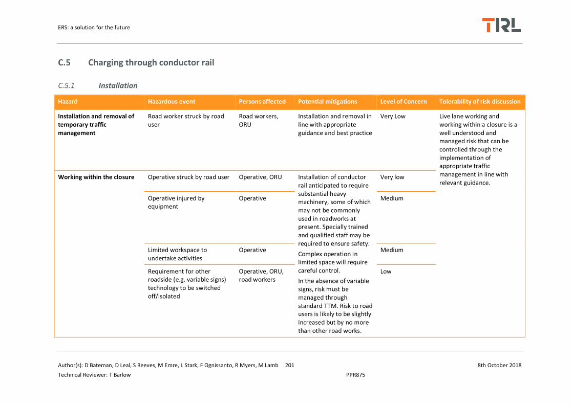
ERS: a solution for the future
Author(s): D Bateman, D Leal, S Reeves, M Emre, L Stark, F Ognissanto, R Myers, M Lamb 201 8th October 2018
Technical Reviewer: T Barlow PPR875
C.5 Charging through conductor rail
C.5.1 Installation
Hazard Hazardous event Persons affected Potential mitigations Level of Concern Tolerability of risk discussion
Installation and removal of temporary traffic management
Road worker struck by road user
Road workers, ORU
Installation and removal in line with appropriate guidance and best practice
Very Low Live lane working and working within a closure is a well understood and managed risk that can be controlled through the implementation of appropriate traffic management in line with relevant guidance.
Working within the closure Operative struck by road user Operative, ORU Installation of conductor rail anticipated to require substantial heavy machinery, some of which may not be commonly used in roadworks at present. Specially trained and qualified staff may be required to ensure safety.
Complex operation in limited space will require careful control.
In the absence of variable signs, risk must be managed through standard TTM. Risk to road users is likely to be slightly increased but by no more than other road works.
Very low
Operative injured by equipment
Operative Medium
Limited workspace to undertake activities
Operative Medium
Requirement for other roadside (e.g. variable signs) technology to be switched off/isolated
Operative, ORU, road workers
Low
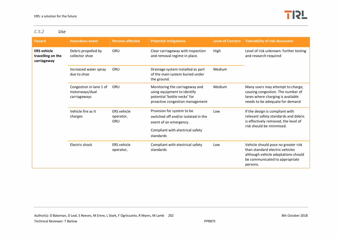
ERS: a solution for the future
Author(s): D Bateman, D Leal, S Reeves, M Emre, L Stark, F Ognissanto, R Myers, M Lamb 202 8th October 2018
Technical Reviewer: T Barlow PPR875
C.5.2 Use
Hazard Hazardous event Persons affected Potential mitigations Level of Concern Tolerability of risk discussion
ERS vehicle travelling on the carriageway
Debris propelled by collector shoe
ORU Clear carriageway with inspection and removal regime in place.
High Level of risk unknown: further testing and research required
Increased water spray due to shoe
ORU Drainage system installed as part of the main system buried under the ground.
Medium
Congestion in lane 1 of motorways/dual carriageways
ORU Monitoring the carriageway and using equipment to identify potential ‘bottle necks’ for proactive congestion management
Medium Many users may attempt to charge, causing congestion. The number of lanes where charging is available needs to be adequate for demand
Vehicle fire as it charges
ERS vehicle operator, ORU
Provision for system to be
switched off and/or isolated in the
event of an emergency.
Compliant with electrical safety
standards
Low If the design is compliant with relevant safety standards and debris is effectively removed, the level of risk should be minimised.
Electric shock ERS vehicle operator,
Compliant with electrical safety standards
Low Vehicle should pose no greater risk than standard electric vehicles although vehicle adaptations should be communicated to appropriate persons.

ERS: a solution for the future
Author(s): D Bateman, D Leal, S Reeves, M Emre, L Stark, F Ognissanto, R Myers, M Lamb 203 8th October 2018
Technical Reviewer: T Barlow PPR875
Electric shock Pedestrian, vulnerable road users
Rail section only live when vehicle is on it.
Provision for system to be
switched off and/or isolated in the
event of an emergency.
Very high A section of rail will be electrified when a vehicle is on top of it, Contact with this rail is likely to be fatal due to high voltage. Special consideration should be given to vulnerable road users (motorcyclists) and vulnerable pedestrians (visually or audibly impaired) This system is unlikely to be suitable for use on roads which permit non-vehicle occupant users
Arcing ORU Appropriate maintenance/inspection schedule conducted by competent persons
Provision for system to be
switched off and/or isolated in the
event of an emergency.
Medium Arcing may affect eyesight or cause distraction and lead to secondary incidents.
This will need to be monitored to
ensure the level of risk posed is
tolerable.
ERS vehicle collision
Modifications affect crashworthiness
ERS vehicle operator Crashworthiness to be tested and evidenced
Low The ERS should not affect vehicle crashworthiness but these need to be assessed for modified vehicles.
Electric shock Road workers, traffic officers, emergency services
Provision for system to be switched off and/or isolated in the event of an emergency.
Medium No additional level of risk likely but
this depends on the vehicle
modifications required.
Increased likelihood of collision with debris
ERS vehicle operator, ORU, Traffic officers, emergency responders, vehicle recovery organisations
Appropriate inspection and removal of debris from the carriageway conducted by competent persons
Medium The position of the shoe under the vehicle may increase the possibility of striking an object as the vehicle travels along the carriageway

ERS: a solution for the future
Author(s): D Bateman, D Leal, S Reeves, M Emre, L Stark, F Ognissanto, R Myers, M Lamb 204 8th October 2018
Technical Reviewer: T Barlow PPR875
ERS vehicle breakdown
Modifications result in slower or more complex recovery
Recovery operative, traffic officers, road users
Safe systems of work to be in place, additional, task related risk assessments carried out to ensure risk is reduced to as low as reasonably practicable
Low It is essential that the ERS does not remain live in the event of a breakdown to eliminate the risk of electrocution. It should not present any additional hazard to third parties. Electric shock Traffic officers,
vehicle recovery organisations
Medium
Electromagnetic emissions
Interference with pacemakers/Impact on health
ORU, pedestrian, emergency services, vehicle recovery operators
Guidance from health professionals. Ensure emissions contained within charging system (shielding)
Low Emissions from conductor rail systems are likely to be so low that the level of risk is likely to be negligible.
Interference with road side signs
ORU, pedestrian, emergency services, vehicle occupant(s), vehicle recovery operators
Ensure emissions contained within charging system (shielding)
Ensure emissions contained within power transfer system (shielding)
Low Emissions from conductor rail
systems are likely to be so low that
the level of risk is likely to be
negligible.
Interference with emergency response equipment
emergency services, vehicle recovery operators
Low
Interference with in-car equipment
ORU, pedestrian, emergency services, vehicle occupant(s), vehicle recovery operators
Low

ERS: a solution for the future
Author(s): D Bateman, D Leal, S Reeves, M Emre, L Stark, F Ognissanto, R Myers, M Lamb 205 8th October 2018
Technical Reviewer: T Barlow PPR875
Interference with radio waves/mobile signals
ORU, pedestrian, emergency services, vehicle occupant(s), vehicle recovery operators
Low
Fire Fire due to system fault/overheating
ORU, pedestrians, emergency services, Operatives
Ensure deign is in line with electrical safety standards
Provision for system to be switched off and/or isolated in the event of an emergency.
Low The level of risk posed will depend on the system design but if design standards are applied this risk should be within a tolerable region.
Fire during charging ORU, pedestrians, emergency services, Operatives
Medium
Collision Collision with roadside equipment
ORU, traffic officers, emergency services
Off road cabinets positioned in accordance with design standards and site specific risk assessment
Low If road side equipment is positioned in a place of relative safety and protected as required, the probability of collision will be minimised.
ERS vehicle other hazards
Injury from vehicle current collector shoe
Vehicle recovery organisation, ORU, pedestrians, emergency services
Retractable in the event of an impact with object
Very Low The tolerability of this risk depends on the system design.
Reduced skid resistance on road surface
Vehicle recovery organisation, ORU, pedestrians, emergency services, vulnerable road users
Surface must have skid resistance at least as good as the existing infrastructure.
Very high It is likely that the level of risk posed can be minimised through appropriate design and materials.
ERS equipment embedded in the road surface
Injured by equipment in the road surface
Vehicle recovery organisation, ORU, pedestrians, emergency services, vulnerable road users
Consultation with vulnerable road user groups.
Ensure ERS is flush with road
surface
Very high The ERS must not increase the risk of injury to any affected parties. The risk of destabilising motorcyclists is needs to be eliminated through the design of the system.

ERS: a solution for the future
Author(s): D Bateman, D Leal, S Reeves, M Emre, L Stark, F Ognissanto, R Myers, M Lamb 206 8th October 2018
Technical Reviewer: T Barlow PPR875
Road surface damage leading to secondary incidents
Recovery operative, ORU, pedestrians, emergency services, vulnerable road users
Testing required to understand long term performance of surface
Medium

ERS: a solution for the future
Author(s): D Bateman, D Leal, S Reeves, M Emre, L Stark, F Ognissanto, R Myers, M Lamb 207 8th October 2018
Technical Reviewer: T Barlow PPR875
C.5.3 Maintenance (routine or emergency)
Hazard Hazardous event Persons affected Potential mitigations Level of Concern Tolerability of risk discussion
Debris Increased requirement to remove debris
Operatives, traffic officer
Automated debris collection system
High Increasing worker exposure to live traffic is unlikely to be tolerable. Consideration will need to be given to eliminating or automating this requirement.
Maintaining equipment in/near carriageway
Road worker struck by road user
Road workers Ensure equipment is installed in a suitable, safe location.
Ensure appropriate traffic management is in place. All maintenance should be conducted by a competent person and in line with electrical safety standards.
Low With appropriate controls in place this risk is likely to be adequately managed. However, significant maintenance requirements may increase road worker exposure to live traffic beyond an acceptable level.
Operative struck by road user Operatives Low
Noise Operatives Medium
General construction related injuries (HAV's, slips, trips and falls)
Operatives Low
Poor quality installation leads to quicker failures
ORU Low
Electrocution from contact with ERS equipment whilst it is live
Operatives Low
Equipment inaccessible Operatives Very low
Road surface damage leading to additional maintenance requirements
Operatives Medium

ERS: a solution for the future
Author(s): D Bateman, D Leal, S Reeves, M Emre, L Stark, F Ognissanto, R Myers, M Lamb 208 8th October 2018
Technical Reviewer: T Barlow PPR875
Increased exposure to risk while maintaining system
Operatives Low
Removing/replacing ERS equipment
Operatives Ensure equipment is installed in a suitable, safe location.
Ensure appropriate traffic management is in place. All maintenance should be conducted by a competent person and in line with electrical safety standards.
Low
Limited work space to undertake activities
Operatives Medium
Operative injured by equipment
Operatives Low
Requirement for other roadside (e.g. variable signs) technology to be switched off/isolated
Operative, ORU, road workers
Low In the absence of variable signs, risk must be managed through standard TTM. Risk to road users is likely to be slightly increased but by no more than other road works.
Implications of burying primary systems under the road surface
Disruption from maintenance Operatives, ORU, emergency services
Ensure rigorous testing of equipment
Ensure equipment is sufficiently encased to minimise the impact of adverse weather or temperature variations.
Low Risks can be reduced by ensuring maintenance requirements are minimised through the design of a robust, reliable system.
Effect on other maintenance activity
Works while the system is live Road workers, operatives
System to be isolated if
workers are working on
the carriageway
Low With appropriate mitigations in place to eliminate the risk of electrocution the risk can be reduced to a tolerable level.

ERS: a solution for the future
Author(s): D Bateman, D Leal, S Reeves, M Emre, L Stark, F Ognissanto, R Myers, M Lamb 209 8th October 2018
Technical Reviewer: T Barlow PPR875
C.5.4 Removal/replacement/decommissioning
Hazard Hazardous event Persons affected Potential mitigations Level of Concern Tolerability of risk discussion
Removing/replacing system
Operative struck by road user
Operatives Removal and replacement of equipment to be conducted by a competent person. Ensure appropriate traffic management is in place. Ensure compliance with relevant standards and guidance.
Very low Consideration should also be given as to the environmental cost of removing a system (recyclable materials, safe disposal)
If tasks are conducted by a competent person in line with relevant safety standards and guidance, the risk is likely to remain tolerable.
Electric shock Operative Low
Sparking equipment Operative sustains burn Operatives Very low

ERS: a solution for the future
Author(s): D Bateman, D Leal, S Reeves, M Emre, L Stark, F Ognissanto, R Myers, M Lamb 210 8th October 2018
Technical Reviewer: T Barlow PPR875
Appendix D ERS Summary Sheets
Below are a series of brief summary sheets providing a description of each branch of ERS technology.

ERS: a solution for the future
Author(s): D Bateman, D Leal, S Reeves, M Emre, L Stark, F Ognissanto, R Myers, M Lamb 211 8th October 2018
Technical Reviewer: T Barlow PPR875
Conductive Overhead
Conductive overhead ERS
Technology description
Siemens AG have developed the only conductive overhead system for
dynamic charging. The technology has evolved from overhead
electrified railway and trolley-bus systems. Cables are suspended 5-
6m above the carriageway, supported by cantilever masts and
powered by roadside substations every 1-4km. The system is only
suitable for freight traffic. Vehicles travelling beneath electrified
cables, above a minimum speed threshold, automatically detect the
systems presence. Vehicle to Infrastructure communications
authenticate the user and allow for debiting for the energy consumed.
After which a pantograph, housed in the cab roof, automatically extend vertically to connect to the cables. Overhead
cables supply continuous power, transmitted through the active pantograph, which drives the vehicles electric motor.
The pantograph can be retracted automatically, in cases of: inactive cable sections, end of electrified routes, or
should the driver need to perform evasive/over-taking manoeuvres. Furthermore the pantograph automatically
adjusts for a high degree of lateral misalignment, placing less of a requirement on the driver to maintain a perfect
driving line. The system supports the use of combinations of full electric and hybrid (parallel and serial) drives for a
number of axle combinations, with small to medium engine and battery sizes. It can also support compressed natural
gas, biofuels, and liquefied petroleum gas drives to support most HGV types. The eHighway programme has worked
in partnership with Scania AB, Volkswagen Group, and Mercedes AMG.
The current version of eHighway can deliver 200kW at an efficiency of 90-97% when travelling at 90km/h (a 500kw
system is under development, which to date has achieved an efficiency of 85% at 80km/h). The system is capable of
automatically detecting system faults and immediately switching off power. Siemens AG have a number of
demonstrations taking place across Sweden, Germany and USA, ranging from 2-12km in length. These
demonstrations have been subjected to a range of environmental conditions, from Stockholm winters to Californian
summers, and have been able to operate successfully. The system can be integrated with existing assets such as
gantries, signage and lighting. Depending on spatial limits it is possible to install on bridges and tunnels. Unlike other
ERS solutions this is the only system that does not directly impact the pavement structure itself; all equipment is
located to the side of, or above the road. Demonstrations have accumulated 1000s of kilometres of data. The system
is highly scalable and can be used in mining shuttling, industrial shuttling (between cargo ports and rail depots), and
highways.
Technology Readiness Level (TRL)
Siemens eHighway currently has a TRL of 8. This is justified through their private track and public road demonstrations
(across Germany, Sweden, and USA) which have validated the final systems and subsystems under real world
conditions and environmental loads.

ERS: a solution for the future
Author(s): D Bateman, D Leal, S Reeves, M Emre, L Stark, F Ognissanto, R Myers, M Lamb 212 8th October 2018
Technical Reviewer: T Barlow PPR875
Benefits and limitations of the technology
Installation and maintenance of the technology
Prior to installation geophysical and spatial surveys are conducted to determine location of masts/equipment. Once
determined, 13m steel masts are driven/bored 1.5m into ground (at 50m spacing) and anchored. Cantilever arms are secured to each mast 7m above the carriageway. Masts can be placed at the verge side (for one direction) or in the
median with 2 arms spanning lanes in both directions. Hangers are fixed to each arm, with suspension and copper
contact lines raised and tensioned (cables installed at a rate of 1km per night). Rectifier substations (housed in a container) are placed on foundations at the roadside and connected to the grid and contact lines. Installation times
vary per site requirements; the 10km Frankfurt system took 5 months to install 10km (the 2km Swedish track took 12
months from inception to commissioning). Most works are done at night time, with lane closures required for some activities (hanging cables). Many activities (installing masts and subsystems) are completed at the roadside,
minimising disruptions. Vehicle restraint systems are also placed for the length of the system. No specially designed
plant is used, mostly equipment used in overhead rail installations.
Off-board equipment (masts, cables) require little to no maintenance over their 30 year lifetime, outside of periodical
safety inspections. It has been designed and tested under harsh winter and summer conditions and in earthquake
prone geographies. Close mast/hanger spacings prevent cables from falling/hanging onto the carriageway in the rare
case of a cable break. Cable levels and tensions are remotely monitored, with the system able to automatically switch
itself off, informing and diverting ERS users. On-board equipment requires inspection/maintenance at normal cycles
(6-12 months). Carbon strips fitted to the pantograph contact the overhead cables and are the main wearing
component. These require replacement every 6-12 months, and are relatively inexpensive. Substation power
electronics may require replacement every 5-10 years.
Impact on the road infrastructure and its maintenance
All infrastructures is above or adjacent to the road, as such overhead ERS has no direct impact on pavements
performance (structural and safety); other than vehicle loads being concentrated in narrow wheelpaths. Its height
does not limit any plant used for routine maintenance. Existing demonstrations have proved the system can be
integrated with existing assets (gantries, lighting, and signage) without compromising their function or visibility. It can
be integrated with tunnels and bridges; provided there is enough clearance (however this would result in addition
costs/complications and may impact existing maintenance of these structures.
Safety and security
Introducing electrified cables on the highway increases the possibility of electrocution, however cables heights ensure
this risk is minimised (and no greater than the risk of a direct collision should anyone be on foot on the carriageway).
Vehicle to Infrastructure communications for energy debiting use tag systems (as found on European toll roads);
which are secure and have established protocols.

ERS: a solution for the future
Author(s): D Bateman, D Leal, S Reeves, M Emre, L Stark, F Ognissanto, R Myers, M Lamb 213 8th October 2018
Technical Reviewer: T Barlow PPR875
Feasibility
Environmental and social impacts
During use, ERS compatible vehicles have zero local emissions. If electricity is produced sustainably (wind, solar,
hydro) then lifecycle emissions are further reduced. Wear of copper rails creates diffuse emissions increasing local
concentrations of heavy metals. Under optimal conditions (sufficient trafficking, renewable energy used), the payback
time for embodied lifecycle and operational greenhouse impacts breakeven after 4 years. Land-use requirements are
minimal as it is installed on land already consumed by highway infrastructure. Manufacturers estimate 6m tonnes of
CO2 can be saved annual if 30% of German trucks used overhead ERS. The visual intrusion of overhead ERS is the
largest negative social impact. Fuel savings are only passed onto freight operators as the system is not suitable for
passenger vehicles.
Installation, operational and maintenance costs
Large scale implementation Infrastructure costs are estimated at €2.2-2.4m/km (including materials, labour; grid connections are estimated to cost €0.4m/km). Maintenance is estimated to cost 2.5% of capital investment annually per km (approximately €55k/km/year). Operational savings, compared to diesel, are estimated by the manufacturer to be €20k for a 40-tonne truck driving 100,00km. Additional costs of ERS truck components are estimated to cost €50k (with projections of €19k in 2050).
Technological feasibility
The Siemens system is the most advanced conductive ERS technology with a TRL 7-8. Power output is up to 500kW with efficiencies between 80-97%. This system is capable of powering medium to heavy goods vehicles. The main challenge for conductive overhead ERS feasibility is to improve their applications for different vehicle types. Currently, interoperability does not exist for conductive overhead
Economic feasibility and potential business model
The overhead system is the least costly type of ERS to install, however the market is limited to HGVs and buses as it cannot be used by cars, therefore the payback on investment could still be over 20 years. As with all ERS concepts the business model is likely to be some form of private public partnership.

ERS: a solution for the future
Author(s): D Bateman, D Leal, S Reeves, M Emre, L Stark, F Ognissanto, R Myers, M Lamb 214 8th October 2018
Technical Reviewer: T Barlow PPR875
Conductive Rail
Technology description
There are three variations of Conductive rail ERS: (1) rails embedded
in pavement (image A), (2) on top of the pavement (image A), and rail
attached to a crash guard (image B). All three concepts use an
intelligent pantograph that extends from either the vehicle underside,
rear or side sill to connect to the electrified rail. Rails are typically
segmented into short lengths to increase safety and minimise the risk
of electrocution. A vehicle equipped with ERS components detect the
rails presence and communicates with the infrastructure to
authenticate and debit the user according to their energy
consumption. Once aligned and authorised, the pantograph extends
to connect to the rails, allowing the vehicle to charge. Depending on
the manufacturer power can be used to directly drive the vehicles
propulsion unit or charge the battery for later use. Once charging is
completed, or should evasive/overtaking manoeuvres be performed
the pantograph can detach from the rail immediately. Most systems
have been designed to operate remotely, automatically detecting
system faults, in which case power is instantly cut from the affected section. There are four key players developing
this type of solution:
Elway AB, Sweden (200kW at 82-95% efficiency) - rail embedded and flush with surface level Alstom AB, France (120kW upto 97% efficiency) - rail embedded and slightly above surface level ElonRoad AB, Sweden (240kW at 90-97% efficiency) - rail fixed above pavement surface level Honda R&D, Japan (450kW at 95% efficiency) - rail fixed to crash guard
Ground level access and high power capabilities means all conductive rail solutions can be used by any vehicle class
(except two-wheelers). Only a couple of these systems have foreign object detection capabilities. Currently only
Elways AB is being trialled on public roads (a 2km installation in Sweden); other are still at earlier stages of
development, but have all undergone track testing in private facilities. All system’s pantographs are capable of
connecting under various lateral misalignments (from 50-400mm), allowing for lane deviations. The power transfer
capabilities of all systems are proven; barriers relate to system design under environmental stresses and vehicle to
infrastructure communications, alongside refining on-board equipment. All require roadside substations and grid
connections, with switching boxes (between rail segments at frequent spacings). All systems are at the pre-
commercial stage of development.
Technology Readiness Level (TRL)
All four systems are at different stages of development, with the Elways AB solution being the most advanced with a
TRL rating of 7. All other systems lie between TRL 4-6. Elways AB has been trialled on a public road since 2017, with
other systems only being tested under laboratory or track conditions.
(A) Rail above or flush with pavement
below carriagew
(B) Rail integrated with crash guard

ERS: a solution for the future
Author(s): D Bateman, D Leal, S Reeves, M Emre, L Stark, F Ognissanto, R Myers, M Lamb 215 8th October 2018
Technical Reviewer: T Barlow PPR875
Benefits and limitations of the technology
Installation and maintenance of the technology
All systems have their own unique installation processes for on-road equipment, However there are some common
features. For instance Alstom and Elways require shallow trenches for rails; all require roadside grid connections at infrequent intervals (typically every 2km) and roadside switching boxes (between rail segments) to be installed.
ElonRoad is completely prefabricated (speeding up installation times) and is simply bolted or bonded (using a bitumen
adhesive) to the pavement. The Honda solution is retrofitted to existing verge side crash guards (provided they meet spatial/clearance requirements of the system), minimising traffic disruptions. Installation times are variable and
uncertain - owing to limited public road demonstrations and the novelty of each system. Trench based solutions
should be has shorter installation times if components are mostly prefabricated. For instance the Elways solution took one month to install and commission a 2km public road track. Other solutions, such as the ElonRoad have the
potential to be rapidly deployed as they are entirely prefabricated and fixed to the pavement surface (however in
their current form they are not suitable for high speed applications).
Some systems will have issues with heavy water flow (Elways and Alstom), some systems this is not an issue (i.e.
ElondRoad where water can pass beneath, or Honda which is above ground); however for Elways and Alstom
solutions water can pool between rails or sit inside pantograph contact channel. Similarly the Elways solution’s
contact channels are susceptible accumulating dirt and debris, meaning the system can be blocked and disrupted
easier than other solutions. All have been designed to have minimal maintenance requirements but notable points
are: Elways requires periodical water jetting to flush stagnant water and debris from inside the rails; Honda will
require periodical levelling checks (in case a vehicle has struck a nearby guard rail and moved the system). The
ElonRoad system is a standalone piece, encased in protective housing; should it require maintenance the affected
section can be removed or quickly replaced. Other than issues caused by environmental deterioration and mechanical
damage from passing vehicles it is not anticipated that this system will require extensive maintenance.
Impact on the road infrastructure and its maintenance
Elways AB and Alstom are embedded solutions so have the potential to cause reflective cracking, and allow water
ingress around the installation if joints are not properly sealed (leading to acceleration of defects). ElonRoad is
secured to the pavement surface with no additional joints; meaning the system does not create any weak spots in the
pavement. The Honda solution is completely separate from the road so does not impact the pavements structural or
safety performance characteristics. In terms of maintenance all systems have an impact on routine activities. For
instance Elways, Alstom and ElonRoad complicate resurfacing activities as these now have to be undertaken either
side of the system instead of the entire lane at once. With respect to winter maintenance all of the above require
theecially
require the use of specially designed ploughs so as to not damage the rails, complicating existing ploughing
strategies. Some solutions cannot be subjected to de-icing salts as this will accelerate corrosion or can act as a
conductor between rails, short circuiting the system. The Honda solution places additional maintenance
requirements on crash guard to ensure they are structurally sound and have not been impacted by errant vehicle.
Similarly crash guards are susceptible to corrosion from roads salts and ploughing could lead to piles of snow, cleared
from the main carriageway, that is now built up at the verge side, where the crash guard is located. With the
exception of Honda, all systems change the profile and skid resistance characteristics of the pavement. Currently
there is little research into the long-term effects of rails embedded in the pavement.

ERS: a solution for the future
Author(s): D Bateman, D Leal, S Reeves, M Emre, L Stark, F Ognissanto, R Myers, M Lamb 216 8th October 2018
Technical Reviewer: T Barlow PPR875
Safety and security
Currently all systems placed in or on the pavement have an impact on the overall skid resistance of that pavement
section, with these issues being addressed in future development. All systems present some level of risk of
electrocution depending on their design, however this is minimised in two ways: (1) making the contact points
difficult to access (as in the Elways solutions); (2) only electrifying the section a vehicle is travelling over. ElonRoad’s
electrified sections are shorter than the length of the passing vehicle, minimising this risk. Some systems have
electrified sections longer than the vehicle passing over it however. The ElonRoad system does however present risks
to road users in that its profile has a 5cm apex above the road surface, making it dangerous for motorcycle users and
vehicles travelling at speed. It could be argued that the risk of electrocution is outweighed by the risk of direct
collision with members of the public attempting to make contact with an on-road system. All systems have been
designed to remotely deactivate instantly should faults/suboptimal conditions be detected.
Environmental and social impacts
All systems are can achieve zero local emissions during use as they are electric drive, with further environmental gains
arising from the use of renewable electricity. The visual impact of all conductive rail systems is minimal as they are
integrated into existing assets. An advantage of conductive rail compared to conductive overhead systems is that they
can be used by many types of road users. There is currently no peer reviewed material to validate the environmental
life cycle performance of each system.
Installation, operational and maintenance costs
As no conductive rail system is commercially available and all are still undergoing development there are no certain costs for installation, operation, and maintenance. However estimates are available in the literature which indicates
the following:
Elways – Installation and materials estimates between €390k-€1m/km (once at commercial scales), with pantograph costing between €500-1000 per unit. Annual infrastructure maintenance costs estimated 1-2% of capital investment.
Alstom – Installation and materials estimates between €1m-€2m/km Pantograph shoe requires replacement every
20000km unknown cost of replacement but not expected to be expensive as is a wearing component.
ElonRoad – Installation and materials estimates between €600k-€1.5m/km. Vehicle costs for pantograph are €5k for
trucks and €2k for cars.
Honda – No estimates currently available other than an installation cost 1/20th of rival inductive solutions
(approximately €100k-€300k/km)

ERS: a solution for the future
Author(s): D Bateman, D Leal, S Reeves, M Emre, L Stark, F Ognissanto, R Myers, M Lamb 217 8th October 2018
Technical Reviewer: T Barlow PPR875
Feasibility
Technological feasibility
The majority of the conductive rail ERS systems scored between TRL 4 and 5. The Elways (from Sweden) systems
appear to be the most advanced conductive rail ERS technology with a TRL 6-7. The majority of the remaining ERS
technologies are still at demonstrator stage and require or are in the process of undertaking on-road trials to improve
their technical feasibility. Power outputs were generally between 120-450kW with efficiencies between 82-97% which
show greater capability for charging HGVs as well as light vehicles. The main challenge for conductive rail ERS
feasibility is to meet safety requirements for surface profile and skid resistance for roads and highways. Currently,
interoperability does not exist for conductive rail ERS systems.
Economic feasibility and potential business models
The conductive rail is intermediate in terms of installation cost compared to the other concepts. As it could be used by
both HGVs and LVs payback on investment could potentially be achieved be within 15 years. As with all ERS concepts
the business model is likely to be some form of private public partnership.

ERS: a solution for the future
Author(s): D Bateman, D Leal, S Reeves, M Emre, L Stark, F Ognissanto, R Myers, M Lamb 218 8th October 2018
Technical Reviewer: T Barlow PPR875
Inductive (wireless)
Technology description
There are many variations of dynamic inductive power transfer
systems; however all function under the same principles –
electromagnetic field resonance between two coils. Primary coil
segments are placed beneath the pavement surface, which are
connected to roadside transformers feeding power from the grid. Coil
segments can be 10-50m in length, separated by a switching unit that
controls power to each segment as the vehicle passes. Vehicles are
equipped with a secondary coil (fitted to the underside), control
electronics, BMU, and interface. The action of the two coils passing
over each other induces the electromagnetic current between coils, allowing power to be transferred at specific
frequencies (typically 85kHz). Power is then stored in the on-board batteries for later use. V2I communications
facilitate user authentication and establish debiting. Coils are typically made from litz cable, ferromagnetic material
(which directs, strengthens and shapes the magnetic flux) and an aluminium shielding layer (to prevent EMF leakage).
Power can be transferred across variable air gaps (typically 15-25cm). Ensuring alignment between coils is a critical
factor for efficient transfer.
There are a wide range of systems at different stages of development, however only one manufacturer (Dongwon
OLEV) has a system that is implemented in commercial operations (public bus transit). Other key developers include:
Politecnico di Torino/CRF, Saet Group, Bombardier, Qualcomm/Vedecom, Oak Ridge National Laboratory, INTIS,
Momentum Dynamics, Electreon, CIRCE, and University of California/Stanford/North Carolina State. It is important to
note that all systems have different IPRs, system architectures, communication protocols, coil geometries, air gaps,
power ratings and efficiencies. Generally inductive systems are rated at 20kW or lower (only suitable for light duty
vehicles); however modular designs allow systems to be stacked to achieve higher power transfer. Bombardier and
Momentum Dynamics are developing systems for use by heavy duty vehicles (up to 200kW and 300kW respectively).
Unlike conductive ERS, inductive systems typically achieve lower efficiencies, 70-85%, although >90% is possible.
Technology Readiness Level (TRL) and estimated time to deployment
The majority of systems are still in their technological infancy, with TRL ratings from 3-5. All have demonstrated the
basic power transfer capabilities of their systems under dynamic testing (laboratory and track trials), however many
face challenges regarding communication protocols, signal switching speeds between segments, efficiency, power
levels and interoperability. Dongwon OLEV is the most advanced system with a TRL of 9, which is in use on
commercial bus operations across several South Korean cities. CIRCE has a TRL of 8; this is the only other system that
has been demonstrated on public roads (Electreon also plan to hold public road demonstrations later in 2018/19).
Inductive ERS Concept

ERS: a solution for the future
Author(s): D Bateman, D Leal, S Reeves, M Emre, L Stark, F Ognissanto, R Myers, M Lamb 219 8th October 2018
Technical Reviewer: T Barlow PPR875
Benefits and limitations of the technology
Installation and maintenance of the technology
Most systems have a target design life of 10-15 years, which corresponds to the service life of the pavements wearing courses. They are installed using trench based techniques, typically having shallow constructions in the upper courses to minimise the air gap between primary and secondary coils. Coils are laid in segments, with switching boxes installed at the verge; these are connected to roadside substations with grid connections. Substations and switching units are typically installed at frequent intervals (i.e. between each segment). Some systems also use large batteries for storage and to smooth demand profiles during peak times (these may require concrete foundations). Primary coils are typically overlaid with asphalt and bitumen adhesives, although some can be installed in concrete. Installation times vary for laying the passive components in the carriageway, from days to months per km. Owing to a lack of demonstrations and the relatively low maturity of these systems optimal and quick installation procedures are yet to be defined. Once the primary coils have been installed they are not accessible for maintenance or upgrades. Many manufacturers claim primary coils are maintenance free. Ideally installations will occur at the same time as resurfacing/reconstruction works and should have a similar rate of installation (1km per 3-4 days). Roadside equipment may take much longer to install, especially if grid infrastructure is not available at the roadside, which is common. Roadside equipment will require more frequent maintenance, as some components may have a field service life of 5-6 years. Carriageway works could cause significant network disruptions.
Impact on the road infrastructure and its maintenance
There is very little available information regarding the long-term impacts inductive ERS has on the surrounding
pavement structure. However reflective cracking has been observed in the pavement surrounding OLEV and CIRCE
installations. Some manufacturers are carrying out accelerated pavement testing to better understand ERS
interactions. While the systems should not limit winter maintenance activities, they could potentially cause issues for
resurfacing/overlaying activities. Manufacturers will have to demonstrate to NRAs that their systems are durable and
do not induce or accelerate pavement defects.
Environmental and social impacts
Inductive systems offer similar environmental benefits to conductive systems and electrified transport in general. The most widely cited environmental benefits are zero local emissions (NOx and PM) and if powered by renewables can lead to reductions GHG emissions. Social benefits include fuel cost savings, health benefits (from reduction of tailpipe pollution, and convenience of charging. Social limitations include concerns over EM emissions to human health, and congestion caused by installation. Switching ICE to electric drives may also reduce noise impacts. Further research is needed to understand the life cycle environmental and social impacts of inductive ERS.
Safety and security
The main safety concern of inductive systems relate to the leakage of electromagnetic field emissions and their impact
on human health/interference with medical devices (such as pacemakers). All systems are being designed to meet
standard limits set out by ICNIRP/IEEE, with many developers successfully demonstrating compliance.

ERS: a solution for the future
Author(s): D Bateman, D Leal, S Reeves, M Emre, L Stark, F Ognissanto, R Myers, M Lamb 220 8th October 2018
Technical Reviewer: T Barlow PPR875
Feasibility
Installation, operational and maintenance costs
Estimates of installation costs (including materials and labour) vary from system to system, ranging between €500k-
€6m per km. However these costs are associated with small scale demonstrations. Economies of scale, refined production and installation techniques should help to further reduce to cost of mass implementation. Maintenance is
typically stated as costing 1-2% of the capital investment annually. Estimates of operational savings vary depending on
the size/load of the vehicle, system efficiencies, and distance driven. However literature indicates savings of 40-75% compared to diesel. Further savings could be realised from battery size reductions (which account for a substantial
proportion of EV capital costs.
Technological feasibility
An assessment of technology readiness and market readiness was carried out and showed a wide range inductive ERS
that scored TRL from 2-9. The majority of the inductive ERS systems (50%) scored between TRL 3 and 4, whilst only
two systems had a TRL greater than 6. The KAIST/Dongwon OLEV (from South Korea) appears to be the most
advanced inductive ERS technology with a TRL 9. The majority of the remaining ERS technologies are still at
demonstrator stage and require or are in the process of undertaking on-road trials to improve their technical
feasibility. Power outputs were generally between 2.5-300kW with efficiencies between 70-90%, which show
capability for powering light vehicles and buses only, with the exception of the Bombardier system which is currently
conducting testing with HGVs. The main challenge for inductive ERS functionality is to improve power transfer
efficiency and maintaining it for different vehicle types. Although the SAET and Polito systems are compatible, there is
little or no interoperability for inductive ERS systems.
Economic feasibility and potential business models
The inductive concept has the greatest range in installation cost, if costs are at the lower range of estimates and there
is take-up by both HGVs and LVs the payback time is likely to be short enough to attract investment. However if it is
towards the upper end of the estimate the payback time is likely to be over 20 years. As with all ERS concepts the
business model is likely to be some form of private public partnership.
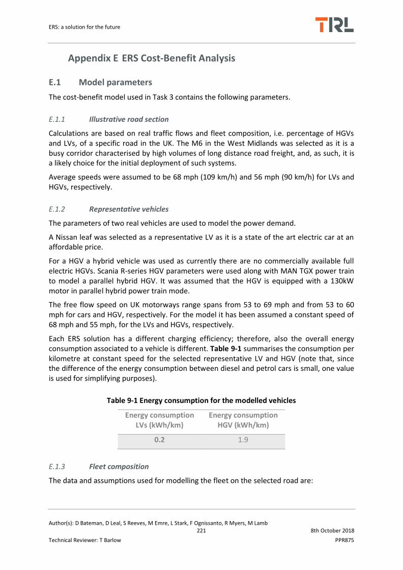
ERS: a solution for the future
Author(s): D Bateman, D Leal, S Reeves, M Emre, L Stark, F Ognissanto, R Myers, M Lamb 221 8th October 2018
Technical Reviewer: T Barlow PPR875
Appendix E ERS Cost-Benefit Analysis
E.1 Model parameters
The cost-benefit model used in Task 3 contains the following parameters.
E.1.1 Illustrative road section
Calculations are based on real traffic flows and fleet composition, i.e. percentage of HGVs and LVs, of a specific road in the UK. The M6 in the West Midlands was selected as it is a busy corridor characterised by high volumes of long distance road freight, and, as such, it is a likely choice for the initial deployment of such systems.
Average speeds were assumed to be 68 mph (109 km/h) and 56 mph (90 km/h) for LVs and HGVs, respectively.
E.1.2 Representative vehicles
The parameters of two real vehicles are used to model the power demand.
A Nissan leaf was selected as a representative LV as it is a state of the art electric car at an affordable price.
For a HGV a hybrid vehicle was used as currently there are no commercially available full electric HGVs. Scania R-series HGV parameters were used along with MAN TGX power train to model a parallel hybrid HGV. It was assumed that the HGV is equipped with a 130kW motor in parallel hybrid power train mode.
The free flow speed on UK motorways range spans from 53 to 69 mph and from 53 to 60 mph for cars and HGV, respectively. For the model it has been assumed a constant speed of 68 mph and 55 mph, for the LVs and HGVs, respectively.
Each ERS solution has a different charging efficiency; therefore, also the overall energy consumption associated to a vehicle is different. Table 9-1 summarises the consumption per kilometre at constant speed for the selected representative LV and HGV (note that, since the difference of the energy consumption between diesel and petrol cars is small, one value is used for simplifying purposes).
Table 9-1 Energy consumption for the modelled vehicles
Energy consumption LVs (kWh/km)
Energy consumption HGV (kWh/km)
0.2 1.9
E.1.3 Fleet composition
The data and assumptions used for modelling the fleet on the selected road are:

ERS: a solution for the future
Author(s): D Bateman, D Leal, S Reeves, M Emre, L Stark, F Ognissanto, R Myers, M Lamb 222 8th October 2018
Technical Reviewer: T Barlow PPR875
• The predicted number of vehicles to 2038 is calculated applying a 2% annual increase1 to the base year number (this taken from the DfT AADF data).
• The fleet split projections for the UK “Outside London” area are taken from the National Atmospheric Emission inventory spreadsheet (NAEI, 2017)
E.2 Assumptions
E.2.1 Technology penetration assumptions
The spreadsheet enables modelling a linear growth of the vehicles using the ERS technology. The parameters which characterise the trend are the starting percentage, the uptake rate and the final maximum penetration rate.
E.2.2 Basis for cost estimates
Cost estimates are based on the following assumptions:
• The infrastructure cost is increased by an ‘optimism bias’ of 60%, as recommended in the DfT’s guideline.
• The annual maintenance is assumed to be 1% of the initial capital costs (in the absence of any empirical evidence, following a suggestion in the Slide In report).
• Administration and management costs for the user registration and payment system: no information was available on what these might be, so the model used an assumption that 2% of the revenue raised from electricity sales would go towards these costs.
• The potential costs of borrowing finance for the implementation of the scheme are not included.
• Electricity is costed using the WebTAG Data Book values for electrified railways, which could be considered to be a comparable system.
• The revenue from sales of electrical power to users is treated as negative cost.
E.3 Benefits assessed
The following benefits are calculated in the model:
The revenue generated through sales of electrical power to private and business users.
Social benefits:
1 From the report prepared for HE “A linear traffic growth of 2% was used as an approximation to 40% growth
between 2010 and 2030, taken from DfT’s 2013 Road Traffic Forecasts”

ERS: a solution for the future
Author(s): D Bateman, D Leal, S Reeves, M Emre, L Stark, F Ognissanto, R Myers, M Lamb 223 8th October 2018
Technical Reviewer: T Barlow PPR875
▪ Carbon dioxide (CO2) emission reductions due to fewer ICE vehicles on the road – the calculation takes into account the CO2 emission from the power plants producing electricity for the EVs.
▪ Air quality benefits arising from Oxides of Nitrogen (NOx) and Particular Matter (PM) emissions reductions at the pipe resulting from vehicles transferring to EV.
E.3.1 Electricity sales
Net revenue from electricity sales to users was calculated from the modelled energy
demand (kWh) for the ERS vehicles and multiplying by the ‘mark-up’ on the price paid for
the first scenario modelled a mark-up of 100% was chosen. At this level the cost per km
running on electricity is around 75% of that when running on diesel, so it is not considered
that a significantly greater mark-up would be practicable, i.e. still providing users with an
incentive for uptake of ERS charging, at currently forecast fuel prices. The upper bound for
charging for electricity is likely to be linked to the retail price for car users since they would
have the opportunity to recharge their vehicles at home. However, operators of heavy
vehicles, unable to travel long distances on their batteries, would have less option about
where to charge and would make a decision to adopt ERS on the basis of its running costs in
comparison with conventional diesel.
Present Values for annual costs and benefits in each year were calculated using a 3.5%
discount rate.
E.3.2 Environmental impact
This section gives describes the procedure followed for the calculation of the CO2, NOx and PM emission savings.
CO2 emissions
Savings in CO2 emission are due to the shift of a portion of the diesel/petrol private LV fleet and diesel LV and HGV business fleet to EVs. The model calculated the annual number of vehicles which move to EVs (see Section E.1.3) and the consequent avoided emissions. To these savings the amount of CO2 produced by power plants for the generation of the electricity used by the EVs is subtracted.
The data and assumptions specifically used for these calculations are:
• Annual CO2 emissions from petrol and diesel vehicles were estimated using the UK Department for Environment, Food and Rural Affairs (DEFRA) Emissions Forecasting Tool (EFT) to 2030, the limit of EFT. Extrapolated figures were used for the years between 2031 and 2038 in order to have a 20 year assessment period.
• The TAG Data Book, which provides the emissions arising from electrical power generation.

ERS: a solution for the future
Author(s): D Bateman, D Leal, S Reeves, M Emre, L Stark, F Ognissanto, R Myers, M Lamb 224 8th October 2018
Technical Reviewer: T Barlow PPR875
• The monetary value of the CO2 emission avoided is calculated using the central damage cost in TAG (non-traded value for the vehicle emissions, and traded value for the power plant emissions -- with 2010 as base year).
Air quality
As for the CO2 savings, the evaluation is based on the number of vehicles which shift from diesel/petrol fuel to electricity. Also for PM and NOx the annual emissions from petrol and diesel vehicles is estimated using the DEFRA Emissions Forecasting Tool (EFT) for the years from 2018 to 2030, after which, the emission factors are kept constant.
Because the impacts of poor air quality are localised, the benefit of reduced emissions varies according to where they take place, i.e. whether there is an exposed population and the extent to which air quality limits are already exceeded. Therefore, when monetising the effects of reduced emissions different values need be to applied in different locations for a tonne of pollutant saved. For NOx there is a ‘damage’ value and an ‘abatement’ value recommended by TRL’s air quality team (close to the ‘central’ valued in the TAG Data Book). The latter is used at locations where the legal limit for nitrogen dioxide is exceeded. For PM the value is derived from the exposed population. In this exercise a value used came from the Interdepartmental group on benefits and costs IGCB Air quality damage costs per tonne for outer London. In both cases therefore, to quantify the values of reduced emissions for a particular section of road modelling would normally be needed.
However, so that an order of magnitude estimate of the emission reduction benefits that might be obtained at locations where there are air quality problems, the monetised savings for a hypothetical 1 km section of road are calculated with and without the higher abatement values.
E.4 Model variables
A number of assumptions were made in the model, and some variables were held constant in order to focus on the impact of modifying the inputs of interest.
Electricity mark-up is constant throughout the 20 year appraisal period
Traffic growth is 2% per annum over the 20 year appraisal period
Percentage HGV is 15%
Traffic levels are 55,018 LV AADF and 9,028 HGV AADF (averages for the UK case study road)
Traffic speed LV 109.4 km/hr and HGV 90.1 km/hr (UK average motorway speeds)
Vehicles not using the technology are ICE powered by fossil fuels (current UK diesel/petrol mix)
The discount rate is 3.5% (as recommended by the UK Treasury)

ERS: a solution for the future
Author(s): D Bateman, D Leal, S Reeves, M Emre, L Stark, F Ognissanto, R Myers, M Lamb 225 8th October 2018
Technical Reviewer: T Barlow PPR875
Appendix F Bibliography
Ahmad, A., Alam, M.S., Varshney, Y. and Khan, R.H. (2017) A State of the Art Review
on Wireless Power Transfer a Step Towards Sustainable Mobility. Transfer, 31, p.32.
Aldammad, M., Ananiev, A. and Kalaykov, I. (2014) Current Collector For Heavy
Vehicles On Electrified Roads. In Proceedings of the 14th Mechatronics Forum
International Conference, Mechatronics, pp. 436-441
Anyapo, C., Teerakawanich, N. and Mitsantisuk, C. (2017) Development Of Multi-
Coils Full-Bridge Resonant Inverter For Dynamic Wireless Power Transfer.
In Electrical Engineering/Electronics, Computer, Telecommunications and Information
Technology (ECTI-CON), 2017 14th International Conference, pp. 588-591.
Apostoaia, C.M. and Cernat, M., (2017) The Inductive Power Transfer System For
Electric Vehicles. In Optimization of Electrical and Electronic Equipment (OPTIM) &
2017 Intl Aegean Conference on Electrical Machines and Power Electronics (ACEMP),
2017 International Conference, pp. 214-220.
Asplund, G. and Rehman, B. (2014) Conductive Feeding of Electric Vehicles from the
Road While Driving. In Electric Drives Production Conference (EDPC), 2014 4th
International, pp. 1-9.
Bandyopadhyay, S., Prasanth, V., Bauer, P. and Ferreira, J.A. (2016) Multi-Objective
Optimisation Of A 1-Kw Wireless IPT Systems For Charging Of Electric Vehicles.
In Transportation Electrification Conference and Expo (ITEC), 2016 IEEE pp. 1-7.
Bojarski, M., Asa, E., Colak, K. and Czarkowski, D. (2017) Analysis And Control Of
Multiphase Inductively Coupled Resonant Converter For Wireless Electric Vehicle
Charger Applications. IEEE transactions on transportation electrification, 3(2), pp.
312-320.
Bosshard, R. and Kolar, J.W. (2016) Inductive Power Transfer for Electric Vehicle
Charging. IEEE Power Electronics Magazine, pp. 22-30.
Campi, T., Cruciani, S., De Santis, V., Maradei, F. and Feliziani, M. (2018) Wireless
Power Transfer (WPT) System For An Electric Vehicle (EV): How To Shield The Car

ERS: a solution for the future
Author(s): D Bateman, D Leal, S Reeves, M Emre, L Stark, F Ognissanto, R Myers, M Lamb 226 8th October 2018
Technical Reviewer: T Barlow PPR875
From The Magnetic Field Generated By Two Planar Coils. Wireless Power
Transfer, 5(1), pp. 1-8.
Chen, K.W.K. and Cheng, K.W.E. (2017) An Investigation Of Coils Used In Dynamic
Wireless Charging For Electric Vehicles. In Power Electronics Systems and
Applications-Smart Mobility, Power Transfer & Security (PESA), 2017 7th
International Conference , pp. 1-7.
Chen, Z., He, F. and Yin, Y. (2016) Optimal deployment of charging lanes for electric
vehicles in transportation networks. Transportation Research Part B:
Methodological, 91, pp. 344-365.
Cirimele, V., Freschi, F., Giaccone, L., Pichon, L. and Repetto, M. (2017) Human
Exposure Assessment In Dynamic Inductive Power Transfer For Automotive
Applications. IEEE Transactions on Magnetics, 53(6), pp. 1-4.
Daga, A., Miller, J.M., Long, B.R., Kacergis, R., Schrafel, P. and Wolgemuth, J. (2017)
Electric Fuel Pumps for Wireless Power Transfer: Enabling Rapid Growth In The
Electric Vehicle Market. IEEE Power Electronics Magazine, 4(2), pp. 24-35.
Dai, Z., Wang, J., Long, M. and Huang, H. (2017) A Witricity-Based High-Power Device
for Wireless Charging of Electric Vehicles. Energies, 10(3), p.323.
Debbou, M. and Colet, F. (2016) Inductive wireless power transfer for electric vehicle
dynamic charging. In Emerging Technologies: Wireless Power Transfer (WoW), 2016
IEEE PELS Workshop on pp. 118-122.
Edfeldt, E. and Andersson, S. (2013) Electric Road Systems for Trucks, KTH Royal
Institute of Technology MSC Thesis, Stockholm, Sweden.
England, H. (2015) Feasibility Study: Powering Electric Vehicles on England’s Major
Roads. Published by: Highways England Company
Foote, A. and Onar, O.C. (2017) A Review Of High-Power Wireless Power Transfer.
In Transportation Electrification Conference and Expo (ITEC), 2017 IEEE, pp. 234-240.
Foote, A., Ozpineci, B., Chinthavali, M. and Li, J.M. (2016) Sizing Dynamic Wireless
Charging For Light-Duty Electric Vehicles In Roadway Applications. In Emerging
ERS: a solution for the future
Author(s): D Bateman, D Leal, S Reeves, M Emre, L Stark, F Ognissanto, R Myers, M Lamb 227 8th October 2018
Technical Reviewer: T Barlow PPR875
Technologies: Wireless Power Transfer (WoW), 2016 IEEE PELS Workshop, pp. 224-
230.
Galigekere, V.P., Onar, O.C., Chinthavali, M. and Wang, Z.J. (2017) Load Power
Agnostic 6.6 Kw Wireless EV Charger With LCL Tuned Primary And Secondary Side
Regulation. In Energy Conversion Congress and Exposition (ECCE), 2017 IEEE, pp.
4839-4844.
García-Vázquez, C.A., Llorens-Iborra, F., Fernández-Ramírez, L.M., Sánchez-Sainz, H.
and Jurado, F. (2016) Evaluating Dynamic Wireless Charging Of Electric Vehicles
Moving Along A Stretch Of Highway. In Power Electronics, Electrical Drives,
Automation and Motion (SPEEDAM), 2016 International Symposium, pp. 61-66.
Gardner, T. (2017) Wireless Power Transfer Roadway Integration.
González-Santini, N.S., Ozpineci, B., Chinthavali, M. and Peng, F.Z. (2017) The Effects
Of The Resonant Network And Control Variables On The Dc-Link Capacitor Of A
Wireless Charging System. In Transportation Electrification Conference and Expo
(ITEC), 2017 IEEE, pp. 626-631.
Gori, P.A., Sadarnac, D., Caillierez, A. and Loudot, S. (2017) Sensorless Inductive
Power Transfer System For Electric Vehicles: Strategy And Control For Automatic
Dynamic Operation. In Power Electronics and Applications (EPE'17 ECCE Europe),
2017 19th European Conference, p. 1.
Helber, S., Broihan, J., Jang, Y.J., Hecker, P. and Feuerle, T. (2018) Location Planning
for Dynamic Wireless Charging Systems for Electric Airport Passenger
Buses. Energies, 11(2), p.258.
Jones, P.T. and Onar, O. (2014) Impact Of Wireless Power Transfer In Transportation:
Future Transportation Enabler, Or Near Term Distraction. In Electric Vehicle
Conference (IEVC), 2014 IEEE International, pp. 1-7.
Kamineni, A., Covic, G.A. and Boys, J.T. (2017) Self-Tuning Power Supply For Inductive
Charging. IEEE Transactions on Power Electronics, 32(5), pp. 3467-3479.

ERS: a solution for the future
Author(s): D Bateman, D Leal, S Reeves, M Emre, L Stark, F Ognissanto, R Myers, M Lamb 228 8th October 2018
Technical Reviewer: T Barlow PPR875
Karakitsios, I. and Hatziargyriou, N. (2017) Bifurcation In Dynamic Inductive Charging
Of Electric Vehicles. In PowerTech, 2017 IEEE Manchester, pp. 1-6.
Karakitsios, I., Palaiogiannis, F., Markou, A. and Hatziargyriou, N. (2018) Optimizing
The Energy Transfer, With A High System Efficiency In Dynamic Inductive Charging Of
Evs. IEEE Transactions on Vehicular Technology.
Karlsson, C. (2015) Developing, Constructing and Testing of a Contact System to the
Elways Track, Chalmers University of Technology MSc Thesis, Gothenburg, Sweden
Kontou, A. and Miles, J. (2015) Electric Buses: Lessons To Be Learnt From The Milton
Keynes Demonstration Project. Procedia engineering, 118, pp.1137-1144.
Lee, J.Y., Lin, T.H. and Chen, I.L. (2017) Design and Implementation Of Contactless
Power Track System With Improved Inductively Coupled Structure. In Future Energy
Electronics Conference and ECCE Asia (IFEEC 2017-ECCE Asia), 2017 IEEE 3rd
International, pp. 444-449.
Lehmann, L. (2016) Technical Review of eHighway (ENUBA), CEDR Workshop on
Electric Roads, Federal Highway Research Institute (BASt), Germany
Li, J. (2017) Research Progress Of Wireless Power Transmission Technology and the
Related Problems. In AIP Conference Proceedings, 1(1820) p. 090023
Lindgren, L. (2015) Full Electrification of Lund City Bus Traffic – A Simulation Study,
Lund University
Liu, C., Jiang, C. and Qiu, C. (2017) Overview Of Coil Designs For Wireless Charging Of
Electric Vehicle. In Emerging Technologies: Wireless Power Transfer (WoW), 2017
IEEE PELS Workshop, pp. 1-6.
Lu, F., Zhang, H. and Mi, C. (2017) A Review on the Recent Development of
Capacitive Wireless Power Transfer Technology. Energies, 10(11), p.1752.
Madzharov, N. and Petkov, V.,(2016) Innovative Solution Of Static And Dynamic
Contactless Charging Station For Electrical Vehicles. In PCIM Europe 2016;
International Exhibition and Conference for Power Electronics, Intelligent Motion,
Renewable Energy and Energy Management; Proceedings pp. 1-8.

ERS: a solution for the future
Author(s): D Bateman, D Leal, S Reeves, M Emre, L Stark, F Ognissanto, R Myers, M Lamb 229 8th October 2018
Technical Reviewer: T Barlow PPR875
MAGMENT (2017) Dynamic Wireless Charging Powered by Stored Solar Energy,
Elektromobilitat der Zukunft Fachsymposium , September 2017
Manshadi, S.D., Khodayar, M.E., Abdelghany, K. and Uster, H. (2017) Wireless
Charging of Electric Vehicles In Electricity And Transportation Networks. IEEE
Transactions on Smart Grid.
Mazharov, N.D., Hristov, S.M., Dichev, D.A. and Zhelezarov, I.S. (2017) Some
Problems of Dynamic Contactless Charging of Electric Vehicles. Acta Polytechnica
Hungarica, 14(4)
Miller, J.M., Onar, O.C. and Chinthavali, M. (2015) Primary-Side Power Flow Control
Of Wireless Power Transfer For Electric Vehicle Charging. IEEE Journal of Emerging
and Selected Topics in Power Electronics, 3(1), pp. 147-162.
Mohamed, A.A.S., Berzoy, A. and Mohammed, O. (2016) Predictive Active Power-
Flow Control Of Two-Way Wireless Power Transfer System In V2G Services. In Power
Electronics Conference (SPEC), IEEE Annual Southern, pp. 1-6.
Moultak, M., Lutsey, N. and Hall, D. (2017) Transitioning to Zero-Emission Heavy-
Duty Freight Vehicles.
Mude, K.N., Outeiro, M.T. and Carvalho, A. (2017) In-Motion Wireless Power
Transfer: Technology, Infrastructure, Challenges And Market Scenario. In Industrial
Technology (ICIT), 2017 IEEE International Conference, pp. 1550-1554.
Najafi, N., Rajaei, A. and Mardaned, M. (2015) Design And Analysis Of Energy
Transfer System Through Inductive Power Transfer (IPT) Connected To A Solar
Panel. Ciência e Natura, 37, pp. 415-426.
Nicolaides, D. and Miles, J., 2015. Wireless Electric Charge-on-the-move: A
Sustainability Appraisal of the Potential for the UK Transport Application. J.
Multidiscip. Eng. Sci. Technol, 2(8), pp. 2238-2246.
Nicolaides, D., McMahon, R., Cebon, D. and Miles, J. (2016) A National Power
Infrastructure for Charge-On-The-Move. In Emerging Technologies: Wireless Power
Transfer (WoW), 2016 IEEE PELS Workshop, pp. 180-185.

ERS: a solution for the future
Author(s): D Bateman, D Leal, S Reeves, M Emre, L Stark, F Ognissanto, R Myers, M Lamb 230 8th October 2018
Technical Reviewer: T Barlow PPR875
Nisshagen, M. and Sjostrand, E. (2017) Wireless Power Transfer Using Resonant
Inductive Coupling – Design and Implementation of an IPT System with One Meter
Air Gap in the Region Between Near-Range and Mid-Range, Chalmers University of
Technology MSc Thesis, Gothenburg, Sweden.
Omar, A.Z.B., Nguyen, K.P., Honda, Y., Matsumoto, N., Hanafi, Z.A.B., Hoshikawa, A.
and Fujita, G.(2017) Towards Japan’s Future EV-Friendly Highway Concept with In-
motion Road-Embedded Wireless Chargers.
Onar, O.C., Campbell, S.L., Seiber, L.E., White, C.P. and Chinthavali, M. (2016) A High-
Power Wireless Charging System Development And Integration For A Toyota RAV4
Electric Vehicle. In Transportation Electrification Conference and Expo (ITEC), 2016
IEEE, pp. 1-8.
Onar, O.C., Campbell, S.L., Seiber, L.E., White, C.P. and Chinthavali, M. (2016)
Vehicular Integration Of Wireless Power Transfer Systems And Hardware
Interoperability Case Studies. In Energy Conversion Congress and Exposition (ECCE),
2016 IEEE, pp. 1-8.
Onar, O.C., Miller, J.M., Campbell, S.L., Coomer, C., White, C.P. and Seiber, L.E. (2013)
Oak Ridge National Laboratory Wireless Power Transfer Development For
Sustainable Campus Initiative. In Transportation Electrification Conference and Expo
(ITEC), 2013 IEEE, pp. 1-8
Patil, D., McDonough, M.K., Miller, J.M., Fahimi, B. and Balsara, P.T. (2018) Wireless
Power Transfer for Vehicular Applications: Overview and Challenges. IEEE
Transactions on Transportation Electrification, 4(1), pp. 3-37.
Ruddell, S., Thrimawithana, D.J. and Madawala, U.K. (2017) December. A Wireless
Power Transfer System Based On A Modified Full Bridge For Dynamic EV Charging.
In Power Electronics Conference (SPEC), 2017 IEEE Southern, pp. 1-5.
Ruffo, R., Cirimele, V., Diana, M., Khalilian, M., La Ganga, A. and Guglielmi, P. (2018)
Sensorless Control Of The Charging Process Of A Dynamic Inductive Power Transfer
System With Interleaved Nine-Phase Boost Converter. IEEE Transactions on Industrial
Electronics.

ERS: a solution for the future
Author(s): D Bateman, D Leal, S Reeves, M Emre, L Stark, F Ognissanto, R Myers, M Lamb 231 8th October 2018
Technical Reviewer: T Barlow PPR875
Russer, J.A., Haider, M., Weigelt, M., Becherer, M., Kahlert, S., Merz, C., Hoja, M.,
Franke, J. and Russer, P. (2017) A System For Wireless Inductive Power Supply of
Electric Vehicles While Driving Along The Route. In Electric Drives Production
Conference (EDPC), 2017 7th International, pp. 1-6.
Schulte, J. and Ny, H. (2018) Electric Road Systems: Strategic Stepping Stone on the
Way towards Sustainable Freight Transport?. Sustainability, 10(4), p.1148.
Shahriari Nasab, P. and Moallem, M. (2014) Design Improvement of the inductive
link of a contactless energy charging system. In Electric Vehicle Conference (IEVC),
2014 IEEE International, pp. 1-5.
Shekhar, A., Prasanth, V., Bauer, P. and Bolech, M. (2015) Generic Methodology For
Driving Range Estimation Of Electric Vehicle With On-Road Charging.
In Transportation Electrification Conference and Expo (ITEC), 2015 IEEE, pp. 1-8.
Shi, L., Yin, Z., Jiang, L. and Li, Y. (2017) Advances In Inductively Coupled Power
Transfer Technology For Rail Transit. CES Transactions on Electrical Machines and
Systems, 1(4), pp. 383-396.
Talbot, J. (2014) Milton Keynes Electric Bus Demonstration Project, ARUP MASP
presentation.
Throngnumchai, K., Hanamura, A., Naruse, Y. and Takeda, K. (2013) Design And
Evaluation Of A Wireless Power Transfer System With Road Embedded Transmitter
Coils For Dynamic Charging Of Electric Vehicles. World Electric Vehicle Journal, 6(4),
pp. 848-857.
Un-Noor, F., Padmanaban, S., Mihet-Popa, L., Mollah, M.N. and Hossain, E. (2017) A
Comprehensive Study of Key Electric Vehicle (EV) Components, Technologies,
Challenges, Impacts, and Future Direction of Development. Energies, 10(8), p.1217.
Veyrunes, P., Duprat, P. and Hourtane, J.L., (2017) Ground-Level Feeding Systems
From Rail To Road. In Transportation Electrification Asia-Pacific (ITEC Asia-Pacific),
IEEE Conference and Expo, pp. 1-4.

ERS: a solution for the future
Author(s): D Bateman, D Leal, S Reeves, M Emre, L Stark, F Ognissanto, R Myers, M Lamb 232 8th October 2018
Technical Reviewer: T Barlow PPR875
Yilmaz, M., Buyukdegirmenci, V.T. and Krein, P.T. (2012) General Design
Requirements And Analysis Of Roadbed Inductive Power Transfer System For
Dynamic Electric Vehicle Charging. In Transportation Electrification Conference and
Expo (ITEC), 2012 IEEE pp. 1-6.
Zaheer, A., Neath, M., Beh, H.Z.Z. and Covic, G.A. (2017) A Dynamic EV Charging
System for Slow Moving Traffic Applications. IEEE Transactions on Transportation
Electrification, 3(2), pp. 354-369.

Electric Road Systems: a solution for the future
TRL
Crowthorne House, Nine Mile Ride, Wokingham, Berkshire, RG40 3GA, United Kingdom T: +44 (0) 1344 773131 F: +44 (0) 1344 770356 E: [email protected] W: www.trl.co.uk
ISBN
PPR875


