4-1 Cisco XR 12404 Router Installation Guide OL-13830-02 CHAPTER 4 Troubleshooting the Installation This chapter provides troubleshooting guidelines for Cisco XR 12404 router. If the solutions provided in this chapter do not make the router fully functional, contact your Cisco service representative for assistance. • Identifying Startup Problems, page 4-2 • Problem-Solving with Subsystems, page 4-5 • Troubleshooting an AC Power Subsystem, page 4-6 • Troubleshooting the DC Power Subsystem, page 4-9 • Troubleshooting the Processor Subsystem, page 4-13 • Troubleshooting the Cooling Subsystem, page 4-24
Transcript
CiscOL-13830-02
C H A P T E R 4
Troubleshooting the Installation
This chapter provides troubleshooting guidelines for Cisco XR 12404 router. If the solutions provided in this chapter do not make the router fully functional, contact your Cisco service representative for assistance.
• Identifying Startup Problems, page 4-2
• Problem-Solving with Subsystems, page 4-5
• Troubleshooting an AC Power Subsystem, page 4-6
• Troubleshooting the DC Power Subsystem, page 4-9
• Troubleshooting the Processor Subsystem, page 4-13
• Troubleshooting the Cooling Subsystem, page 4-24
4-1o XR 12404 Router Installation Guide
Chapter 4 Troubleshooting the InstallationIdentifying Startup Problems
Identifying Startup ProblemsStartup problems are commonly due to power source failures or to a card not properly seated in the backplane. Although an overtemperature condition is unlikely at initial startup, the environmental monitoring functions are included here because they also monitor internal voltages.
When you start up the router for the first time, you should observe the startup sequence. The normal startup sequence is as follows:
• Each card in the system has an MBus module and at least one DC-DC converter. Each MBus module controls the DC-DC converter. The MBus module receives +5 VDC directly from the power supplies through the backplane. When the power supply is powered on, each MBus module boots from an onboard electrically erasable programmable read-only memory (EEPROM) device. Each MBus module processor reads a set of identification pins on the card to the backplane connector telling the MBus module processor what kind of card it is mounted on, which in turn, determines how the MBus module will function.
• The consolidated switch fabric (CSF) containing the system clock, immediately powers up.
• The MBus module on the RP monitors the progress of the clock and scheduler card power on. When the CSF has powered up, the MBus module on the RP turns on its DC-DC converter powering up the RP.
• The RP sends instructions to each line card to power up. Each line card processor begins to perform its own boot process and notifies the RP when the boot process is complete through its MBus module.
• As the boot process progresses for each card, the status of the card is shown on the alphanumeric LED displays. The left display is powered by the DC-DC converter on the card; the right display is powered by the DC voltage that powers the MBus module.
By checking the state of the LEDs on the power supplies and the alphanumeric displays on the RP and line cards, you can determine when and where the system failed in the startup sequence.
4-2Cisco XR 12404 Router Installation Guide
OL-13830-02
Chapter 4 Troubleshooting the InstallationIdentifying Startup Problems
Using the System LEDs to TroubleshootYou can determine when and where the system failed in the startup sequence by checking the state of the LEDs on the power modules and line cards, and on the alphanumeric displays on the RP.
You should observe the following when you power on the router:
• INPUT OK LEDs—These LEDs should light immediately; they should remain on as long as the system is receiving power from the power source and the power switch is in the on position.
The LEDs indicate the status of the PEM and internal DC voltages. If either LED does not light, or if they shut off while the power switch is on, there could be a problem with either the power source, the internal DC voltage used to power internal components, or the cooling subsystem.
The LEDs remain on when all of the following conditions are met:
– AC PEMs: The AC power source voltage is operating between 100-120 VAC and is using 15-Amp service for North America, or is operating between 185-264 VAC and is using 10-Amp service in an international environment.
– DC PEMs: The DC power source is supplying power to the PEMs and the power switch is in the on position.
Note The amber OUTPUT FAIL LED is normally off, but lights if the PEM detects a fault.
– The power supplies are providing –48 VDC to internal components.
4-3Cisco XR 12404 Router Installation Guide
OL-13830-02
Chapter 4 Troubleshooting the InstallationIdentifying Startup Problems
– All internal DC voltages are within tolerance.
If the AC power source or any of the internal DC voltages exceed allowable tolerances, the OUTPUT OK LED shuts off, or will shut off shortly after you turn on the power. Because both the RP (which uses +2.5, +3.3 and +5 VDC), and the fan tray assembly (which uses –48 VDC) are required for operation, a problem with any of the internal DC lines can prevent the system from starting up or continuing operation.
For example, if there is a problem with the –48 VDC line that supplies the fan tray, the system powers up, but will also recognize that the fans are not operating. The system will initiate a fan failure shutdown sequence, display the appropriate warning messages, and then shut down after two minutes.
If there is a problem with any of the other DC lines, the RP will not be able to initialize the system software, so the system might attempt to start up and fail during the boot sequence.
• The fan tray immediately begins operating.
• The alphanumeric LED displays on the RP indicate the following:
– The left display indicates which RP software component is running.
– The right display indicates the phase of the boot process that is currently occurring.
4-4Cisco XR 12404 Router Installation Guide
OL-13830-02
Chapter 4 Troubleshooting the InstallationProblem-Solving with Subsystems
Problem-Solving with SubsystemsThe key to solving router problems is to isolate the problem to a specific subsystem. The first step in solving startup problems is to compare what the system is doing to what it should be doing. Because a startup problem is usually attributable to a single component, it is more efficient to first isolate the problem to a subsystem rather than trying to troubleshoot each component in the system.
For troubleshooting purposes, the Cisco XR 12404 router consists of the following subsystems:
• Power subsystem—Includes the following components:
– AC-input power supplies or DC-input power entry modules (PEMs). The Cisco XR 12404 router can be configured for source AC or source DC power (you can not mix AC and DC power).
– Chassis backplane power distribution. The –48 VDC power from the power supplies is transferred to the chassis backplane, which distributes –48 VDC power to the cards in the card cages through the backplane connectors.
– DC-DC converters. Each card in the router is equipped with DC-to-DC converters. These converters are controlled by the MBus module on each card. The DC-to-DC converters take –48 VDC and convert it into the voltages required by the card circuitry.
• Processor subsystem—The processor subsystem includes the RP and all line cards. The RP downloads a copy of the Cisco IOS XR image to each line card processor. The system uses alphanumeric LED displays to display status and error messages, which can help in troubleshooting.
• Cooling subsystem—The cooling subsystem is comprised of one fan tray assembly and one air filter. The fan tray assembly and air filter are hot swappable, and can be replaced while the system is running.
Caution Replace the fan tray assembly within 2 minutes of removing it from the chassis or the router will go into a critical failure mode and shutdown due to an overtemp condition.
4-5Cisco XR 12404 Router Installation Guide
OL-13830-02
Chapter 4 Troubleshooting the InstallationTroubleshooting an AC Power Subsystem
Troubleshooting an AC Power SubsystemAC PEMs provide –48 VDC OUTPUT. The +5 VDC OUTPUT from the CSF powers the MBus module on each card in the system. The MBus module, in turn, control the DC-DC converters also present on each card in the system. The DC-DC converter takes –48 VDC from the power supply and converts it into +2.5, +3.3 and +5 VDC, which is distributed to the card circuitry.
AC PEMs are monitored by the MBus module and the RP for over- or undervoltage and over- or undercurrent conditions.
Begin checking the power subsystem by first looking at the LEDs on the power supply. The INPUT OK LED on an AC PEM lights when AC power is applied; the OUTPUT OK LED lights when the PEM power switch is turned on.
Figure 4-1 shows the location of the LEDs on the AC PEM (item 5).
Figure 4-1 AC PEM
1 AC PEM handle 4 Power cord receptacle
2 On/Off switch 5 LEDs
3 Bail Latch 6 Captive screws
INPUTOK OUTPUT
FAIL
INPUT100-240V12A50/80HZ
OUTPUTOK
6628
9
456
1 2 3
4-6Cisco XR 12404 Router Installation Guide
OL-13830-02
Chapter 4 Troubleshooting the InstallationTroubleshooting an AC Power Subsystem
Table 4-1 summarizes the function of these indicators.
The following conditions must exist for an AC PEM to operate normally:
• The PEM is fully seated in its bay and the ejector levers are secured.
• AC-input power is within the required range is correctly connected to PEMs.
• The power switch on the PEM is switched on.
• The green LEDs labeled OUTPUT OK and INPUT OK on the PEM are on.
To help isolate a problem with an AC-input power supply, follow these steps:
Step 1 If the OUTPUT OK LED is off, verify that the power supply is fully seated in its bay, the ejector levers are flush with the power supply faceplate, and the captive screws are secured.
• If the OUTPUT OK LED is on, go to Step 6.
• If the OUTPUT OK LED remains off, go to Step 2
Step 2 Check the AC power source.
• Check the AC power cord from the power source to the router.
– Verify that the power cord is seated securely in the PDU and the AC outlet.
– Verify that the power cord is not worn or damaged. If the insulation appears cracked or broken, or the plugs appear loose, replace the power cord with a new power cord.
• Verify that the AC power source circuit breaker is on and has not tripped, and that the circuit breaker has the proper current rating.
Table 4-1 DC-Input PEM LED Indicators
LED Label Color Function
OUTPUT OK Green PEM is operating normally in a powered-on condition.
INPUT OK Green DC power is present at the PEM input and within the specified limits.
OUTPUT FAIL Amber Indicates a failure in the PEM.
4-7Cisco XR 12404 Router Installation Guide
OL-13830-02
Chapter 4 Troubleshooting the InstallationTroubleshooting an AC Power Subsystem
• Verify that each power supply in the router is attached to a separate AC power source.
• If the router is connected to an uninterruptable power supply (UPS), verify that the UPS is functioning correctly. Note that there might be a UPS for each power supply in the system.
If the AC power source wiring appears to be okay, but the power supply OUTPUT OK LED remains off, go to Step 3.
Step 3 Plug the power cord into a different, but compatible AC outlet.
• If the power supply OUTPUT OK LED is on, the original AC outlet is faulty and cannot be used. Notify the appropriate facilities personnel and go to Step 6.
• If the power supply OUTPUT OK LED remains off, go to Step 4.
Step 4 Exchange the existing power cord for another power cord.
• If the power supply OUTPUT OK LED is on, the original power cord is faulty and must be replaced. The AC portion of the power supply is working normally, go to Step 6.
• If the OUTPUT OK LED still fails light when connected to a different power source with a new power cord, the power supply is probably faulty. Go to Step 5.
Step 5 If a spare power supply is available, replace the existing module with the spare and restart the system.
• If the OUTPUT OK LED on the spare power supply is on, the power supply is working normally, go to Step 6. The original power supply is faulty and should be returned for replacement.
Step 6 Is the power supply INPUT OK LED on?
• If yes, the power supply is functioning normally.
Note In a Cisco XR 12406 router with two power supplies, the output power from the second power supply is adequate to maintain router operation.
• If no, and there is no other system activity (fan assembly is off; line cards are not powered), the power supply is faulty. Replace the power supply.
4-8Cisco XR 12404 Router Installation Guide
OL-13830-02
Chapter 4 Troubleshooting the InstallationTroubleshooting the DC Power Subsystem
• If no, but the fan assembly is operating, suspect a faulty power supply INPUT OK LED. If the fan assembly is operating, all internal DC voltages are within tolerance. Use the show environment command to check the voltages on each card. The fan assembly uses –48 VDC.
If you are unable to resolve the problem or if you determine that either the power supply or power cable is faulty, contact a service representative for assistance.
Troubleshooting the DC Power SubsystemThe DC PEMs and PDUs provide DC power to the router which is distributed to the card circuitry.
Begin checking the power subsystem by first looking at the three LEDs on the PEM. The INPUT OK LED on an DC PEM is on when DC power is applied, The OUTPUT OK LED is on when the power switch is turned on.
• The amber OUTPUT FAIL LED is normally off, but comes on if the PEM detects a fault.
• The DC PEMs are monitored by the MBus module and the RP for over-or-under voltage and current conditions.
Figure 4-2 shows the location of the LEDs on the PEM.
4-9Cisco XR 12404 Router Installation Guide
OL-13830-02
Chapter 4 Troubleshooting the InstallationTroubleshooting the DC Power Subsystem
Figure 4-2 DC PEM and PDU
Table 4-2 summarizes the function of these indicators.
1 DC PDU 5 On/Off switch
2 DC PEM 6 PDU captive screws
3 PEM captive screws 7 Terminal Block
4 LEDs
INPUT– 48/60V35A
6629
5
INPUTOK OUTPUT
FAIL
OUTPUTOK
56
43
7
1 2 3
Table 4-2 DC-Input PEM LED Indicators
LED Label Color Function
OUTPUT OK Green PEM is operating normally in a powered-on condition.
INPUT OK Green DC power is present at the PEM input and within the specified limits.
OUTPUT FAIL Amber Indicates a failure in the PEM.
4-10Cisco XR 12404 Router Installation Guide
OL-13830-02
Chapter 4 Troubleshooting the InstallationTroubleshooting the DC Power Subsystem
The following conditions must exists for a DC PEM to operate normally:
• The PEM is fully seated in its bay and the ejector levers are secured.
• DC-input power is within the required range is correctly connected to the chassis PDU terminal connector block.
• The circuit breaker on the PEM is switched on.
• The green LEDs labeled OUTPUT OK and INPUT OK are on, and the amber LED labeled OUTPUT FAIL is off.
Follow these steps to help isolate a problem with a DC PEM:
Step 1 Is the OUTPUT FAIL LED on?
• If yes, the PEM is faulty. Replace the PEM.
• If no, go to Step 2.
Step 2 If the INPUT OK LED is off, verify that the PEM is fully seated in its bay, the ejector levers are flush with the PEM faceplate, and the captive screws are secured.
• If the INPUT OK LED comes on, go to Step 6.
• If the INPUT OK LED remains off, go to Step 3.
Step 3 Verify that the PEM circuit breaker switch is on.
• If yes, go to Step 4.
• If no, switch the circuit breaker on.
– If the INPUT OK LED remains off, go to Step 4.
– If the INPUT OK LED comes on, go to Step 6.
4-11Cisco XR 12404 Router Installation Guide
OL-13830-02
Chapter 4 Troubleshooting the InstallationTroubleshooting the DC Power Subsystem
Step 4 Power off the PEM circuit breaker switch and check the DC power source:
• Check the DC power wires from the power source to the router.
– Verify that the power wires are fastened securely at the PDU and the DC source.
– Verify that the power wires are not worn or damaged. If the insulation appears cracked or broken, have the power wires replaced.
• Make sure that the DC power source circuit breaker is on, and that the circuit breaker has the proper current rating.
• Verify that each PEM in the router is attached to a separate DC power source.
• Power on the PEM circuit breaker.
– If the PEM INPUT OK LED comes on, go to Step 6.
– If the PEM INPUT OK LED remains off, go to Step 5.
Step 5 Remove the PEM and insert it in the second bay in the router, or into a bay on another Cisco XR 12404 router.
• If the INPUT OK LED remains off, the PEM is faulty and needs to be replaced.
• If the INPUT OK LED comes on, the input portion of the PEM is working normally, go to Step 6.
Step 6 Is the OUTPUT OK LED on?
• If yes, the power source is good and the PEM is operating normally.
Note In a Cisco XR 12404 router with two power supplies, the output power from the second power supply is adequate to maintain router operation.
• If no, and there is no other system activity (fan assembly is off; line cards are not powered), the PEM is faulty. Replace the PEM.
• If no, but the fan assembly is operating, suspect a faulty OUTPUT OK LED. If the fan assembly is operating, all internal DC voltages are within tolerance. Use the show environment command to check the voltages on each card. The blower module uses –48 VDC.
4-12Cisco XR 12404 Router Installation Guide
OL-13830-02
Chapter 4 Troubleshooting the InstallationTroubleshooting the Processor Subsystem
If you are unable to resolve the problem or if you determine that either the PEM or power wiring is faulty, contact a service representative for assistance.
Troubleshooting the Processor SubsystemThe Cisco XR 12404 router processor subsystem consists of the RP, the line cards, and the CSF card. The system cannot operate unless the RP is installed. The RP and the line cards each have two processors. One processor is the main processor; and the other processor is a component in the MBus module.
• The MBus module begins operation as soon as power is applied to the system. The MBus module determines the type of card it is mounted on and whether it should turn on the DC-DC converter.
• The RP MBus module turns on card power after a brief delay; the line card MBus modules delay turning on power until they receive a command from the RP.
A Cisco XR 12404 router requires that one RP be installed, or the system cannot operate. A line card that is partially connected to the backplane can send incomplete signals to the RP, which could cause the system to hang. If necessary, you can troubleshoot individual line cards, but first make sure that the RP is installed properly and the system software has initialized successfully.
Note The primary RP must be installed in Slot0 which is a narrow slot. If a redundant RP is installed in another slot, a narrow card filler panel must be used to ensure proper air flow through the chassis and electromagnetic compatibility (EMC).
A power-on self-test (POST) runs immediately at power-on to determine the condition of the RP memory. Results are displayed in the alphanumeric LED display as a pass/fail message.
4-13Cisco XR 12404 Router Installation Guide
OL-13830-02
Chapter 4 Troubleshooting the InstallationTroubleshooting the Processor Subsystem
Troubleshooting the RPWhen the router is powered on, the alphanumeric display on the RP indicate the following (Figure 4-3):
• Upper row—Indicates which RP software component is running. At the end of a successful boot process, this display reads MSTR.
• Lower row—Indicates the current phase of the boot process. At the end of a successful boot process, this display reads PRP.
Figure 4-3 RP Alphanumeric Display
Troubleshooting Using the RP Alphanumeric Display
You can use the alphanumeric display to isolate a problem with the RP. The two rows on the alphanumeric display are powered separately:
• The upper row receives power from the DC-to-DC converters on the RP.
• The lower row is powered directly from the MBus on the RP through the chassis backplane.
– If the lower row is not operating, the MBus module may be malfunctioning.
– If the MBus module is operating, the lower row could be on even if the RP failed to powered on.
H10
780
PRO
CE
SSOR
Upper alphanumericLED display (four digits)
Lower alphanumericLED display (four digits)
4-14Cisco XR 12404 Router Installation Guide
OL-13830-02
Chapter 4 Troubleshooting the InstallationTroubleshooting the Processor Subsystem
• If neither the upper nor the lower row is on, but the power modules and the blower modules are operational, the RP may not be installed properly, or the +5 VDC output from the chassis backplane is faulty.
– Make sure that the system is powered on.
– Initialize the RP by ejecting it from the chassis backplane and then resetting it.
Caution The soft reset (NMI) switch is not a mechanism for resetting the RP and reloading the Cisco IOS image. It is intended for software development use. To prevent system problems or loss of data, use the soft reset switch only when instructed by a Cisco certified service representative.
• If both the upper and the lower displays are operating, check the meaning of the messages (see Table 4-3).
When the DC-to-DC converters are powered-on by the MBus module, the RP processor begins the boot process and displays various status messages. Some messages appear briefly; while others appear for several seconds. If the messages appear to stop at a particular point, the boot process may be halted.
– Make a note of the message.
– Turn off power to the router, then turn on the power again to reset the router and start the boot process. If the router halts again, replace the RP.
4-15Cisco XR 12404 Router Installation Guide
OL-13830-02
Chapter 4 Troubleshooting the InstallationTroubleshooting the Processor Subsystem
Table 4-3 Troubleshooting Using the RP Alphanumeric Display Messages
Message Description
LMEMTEST
Running low memory test
LCAHTEST
Initializing lower 15K cache
BSSINIT
Initializing main memory for ROM
NVRAMINIT
Initializing NVRAM
EXPTINIT
Initializing interrupt handlers
TLBINIT
Initializing TLB
CACHINIT
Initializing CPU data and instruction cache
CACHPARY
Enabling CPU cache parity
MEMINIT
Initializing main memory
NVRAMSIZE
Detecting the NVRAM size
PCMCINIT
Initializing the PCMCIA
EXITINIT
Exiting the initialization sequence
IOSUP
Running Cisco XR IOS software
4-16Cisco XR 12404 Router Installation Guide
OL-13830-02
Chapter 4 Troubleshooting the InstallationTroubleshooting the Processor Subsystem
The RP has 8 device or port LED activity indicators that show the status of the Ethernet connections (Figure 4-4).
Figure 4-4 RP LEDs
The RJ-45 port LEDs on the RP indicate:
• Which Flash memory card slot is active.
– Each LED lights when its corresponding PCMCIA slot is accessed (SLOT 0 and SLOT 1).
• Which Ethernet connection is in use.
– 4 RJ-45 Ethernet port activity LEDs indicate link activity (LINK), port enabled (EN), data transmission (TX), and data reception (RX).
• What is occurring on the Ethernet interface.
– 2 Ethernet port-selection LEDs (labeled PRIMARY) identify which of the Ethernet connections are selected. Because both ports are supported on the PRP, the LED on port ETH0 is always on. The LED on port ETH1 lights when it is selected.
LINK Indicates link activity
EN Indicates the port is enabled
TX Indicates data transmission
RX Indicates data reception
RX
TX
PRIMARY
SLOT-1
SLOT-0
LINK
EN
RX
TX
ETH 1ETH 0
LINK
PRIMARY
EN
7069
3
4-17Cisco XR 12404 Router Installation Guide
OL-13830-02
Chapter 4 Troubleshooting the InstallationTroubleshooting the Processor Subsystem
Check the following to help isolate a problem with the RP.
• Are both alphanumeric LED displays on?
– The two displays are powered separately. The left display receives power from the DC-DC converter on the RP. The right display is powered directly from the power supply; therefore, even if the RP has not powered up, its right display could be on. If both displays are off, the RP may not be properly seated in the backplane connector, there might be a problem with the MBus module on the RP, or the system power supply might be off.
• If both displays are on, check the message being displayed. As soon as the DC-DC converter is turned on by the MBus module, the processor on the RP begins the boot process. Status messages are displayed as the boot process continues. If one of the messages appears frozen, the boot process could be halted. Write the message being displayed on a piece of paper. Turn off the PEM power switches, then turn them back on to reset the system and start the boot process again. If the system halts again, the RP could be faulty and may need to be replaced.
– If the PEMs and fans appear operational but none of the RP LEDs or displays are on, suspect that the RP has not been properly installed or that the +5 VDC output from the CSF card is faulty.
– Turn the PEM power switch to the OFF position on each PEM.
– Loosen the two captive screws on the left and right sides of the RP faceplate, and use the ejector levers to eject and reseat the RP. Tighten the captive screws, then power on the system by turning the PEM power switches on.
• Is a Critical, Major, or Minor alarm LED on the CSF card on?
– If any of the three CSF card LEDs is on, a fault has been detected in the system. Check the console for messages indicating the source of the problem.
– There could be a false error indication originating from the RP. You may want to reseat or replace the RP.
Caution The RP reset switch resets the RP and the entire system. To prevent system errors and problems, use it only at the direction of a Cisco-certified service representative.
4-18Cisco XR 12404 Router Installation Guide
OL-13830-02
Chapter 4 Troubleshooting the InstallationTroubleshooting the Processor Subsystem
PRP-3 Alphanumeric LEDs
The following section discusses the alphanumeric LED messages and the console output displayed in sequence for a single PRP-3 and for dual PRP-3. The alphanumeric LED messages help in identifying the state of the route processor and accordingly troubleshooting the problems faced.
Single PRP-3 Scenario
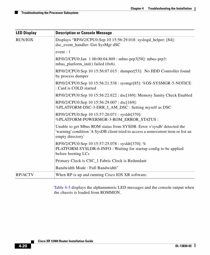
Table 4-4 displays the alphanumeric LED messages and the console output when the chassis is powered on or when the PRP-3 board is inserted into the slot.
Table 4-4 Single PRP-3 Alphanumeric Display LED—Chassis Is Powered ON/Inserting PRP-3
Unable to get Mbus ROM status from SYSDB. Error ='sysdb' detected the 'warning' condition 'A SysDB client tried to access a nonexistent item or list an empty directory'
RP/0/2/CPU0:Sep 10 15:57:25.078 : sysldr[370]: % PLATFORM-SYSLDR-6-INFO : Waiting for startup config to be applied before booting LCs
Primary Clock is CSC_1 Fabric Clock is Redundant
Bandwidth Mode : Full Bandwidth”
RP/ACTV When RP is up and running Cisco IOS XR software.
LED Display Description or Console Message
4-20Cisco XR 12404 Router Installation Guide
OL-13830-02
Chapter 4 Troubleshooting the InstallationTroubleshooting the Processor Subsystem
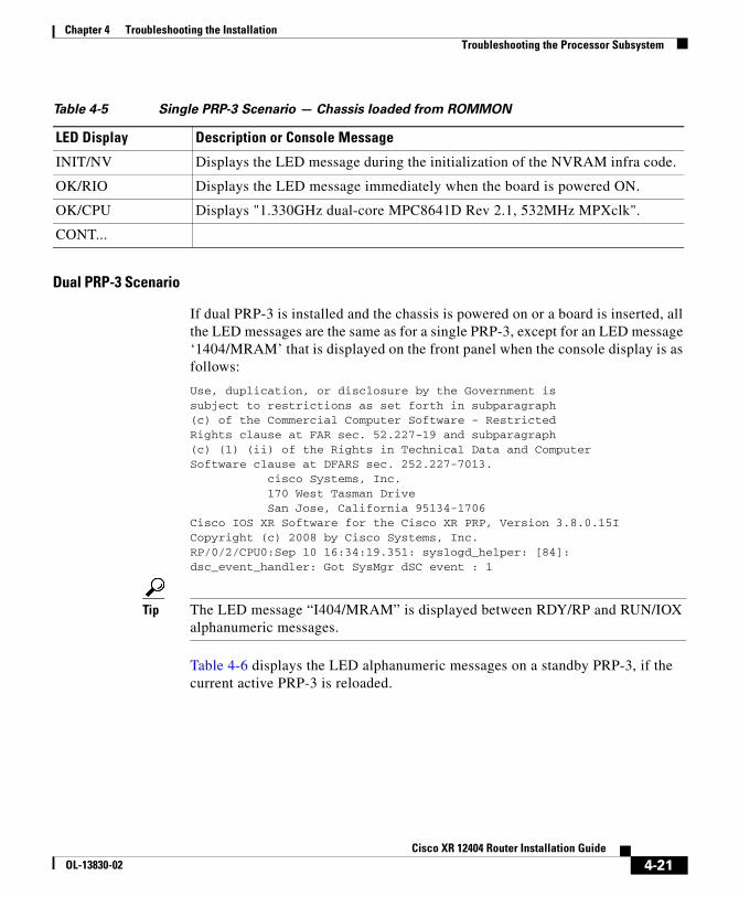
Table 4-5 Single PRP-3 Scenario — Chassis loaded from ROMMON
Dual PRP-3 Scenario
If dual PRP-3 is installed and the chassis is powered on or a board is inserted, all the LED messages are the same as for a single PRP-3, except for an LED message ‘1404/MRAM’ that is displayed on the front panel when the console display is as follows:
Use, duplication, or disclosure by the Government issubject to restrictions as set forth in subparagraph(c) of the Commercial Computer Software - RestrictedRights clause at FAR sec. 52.227-19 and subparagraph(c) (1) (ii) of the Rights in Technical Data and ComputerSoftware clause at DFARS sec. 252.227-7013. cisco Systems, Inc. 170 West Tasman Drive San Jose, California 95134-1706Cisco IOS XR Software for the Cisco XR PRP, Version 3.8.0.15ICopyright (c) 2008 by Cisco Systems, Inc.RP/0/2/CPU0:Sep 10 16:34:19.351: syslogd_helper: [84]: dsc_event_handler: Got SysMgr dSC event : 1
Tip The LED message “I404/MRAM” is displayed between RDY/RP and RUN/IOX alphanumeric messages.
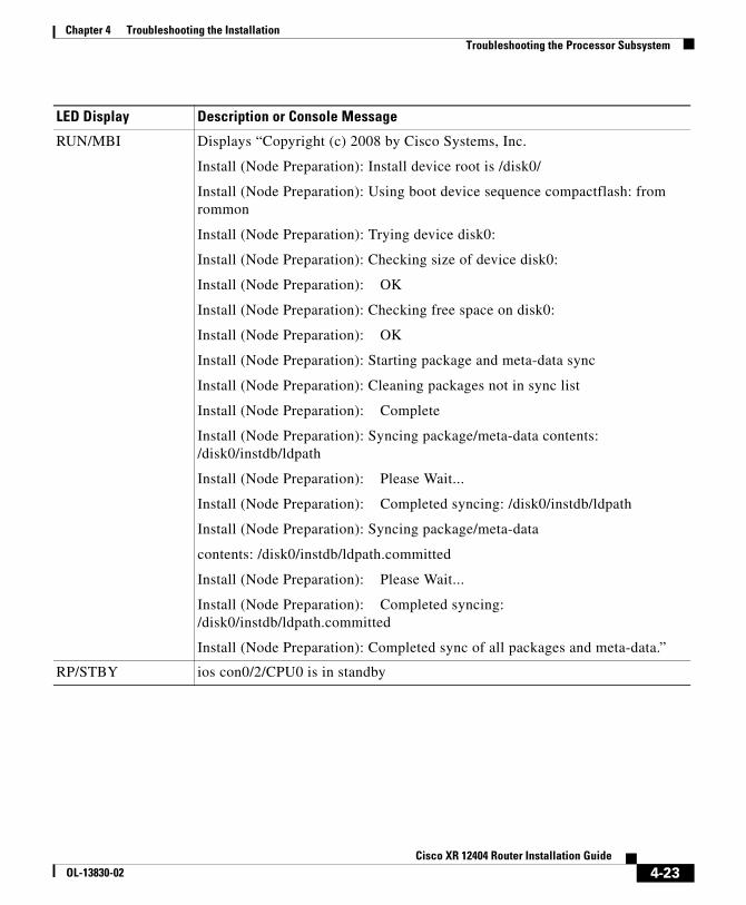
Table 4-6 displays the LED alphanumeric messages on a standby PRP-3, if the current active PRP-3 is reloaded.
LED Display Description or Console Message
INIT/NV Displays the LED message during the initialization of the NVRAM infra code.
OK/RIO Displays the LED message immediately when the board is powered ON.
Install (Node Preparation): Completed sync of all packages and meta-data.”
RP/STBY ios con0/2/CPU0 is in standby
LED Display Description or Console Message
4-23Cisco XR 12404 Router Installation Guide
OL-13830-02
Chapter 4 Troubleshooting the InstallationTroubleshooting the Cooling Subsystem
Troubleshooting the Line CardsAs each line card powers on, a power-on self-test (POST) is performed on the line card memory. A full set of field diagnostics can also be run on a line card from the system console providing a pass/fail message both in the line card alphanumeric LED display and on the system console.
Check the following to help isolate a problem with the line cards:
• Are both banks of alphanumeric LED displays on?
– The two displays are powered separately. The left display receives power from the DC-DC converter on the line card. The right display is powered directly from the power supply. So, even if the line card has not powered up, the right display could be on. If both displays are off, the line card might not be fully plugged into the backplane connector, there might be a problem with the MBus module on the line card, or the system power supply may be off.
– If both displays are on, check the message being displayed. As soon as the DC-DC converter is turned on by the MBus module, the processor on the line card begins the boot process. Status messages are displayed in the alphanumeric displays as the boot process continues on the line card.
The system attempts to boot identical line cards in parallel. Further, the system boots line cards as soon as they are powered on and become available for backup.
During the line card boot process, which occurs immediately after the RP boot process, you can observe the alphanumeric LED displays on each line card. For additional information about the displays and definitions, see the Cisco IOS XR Troubleshooting Guide (see “Obtaining Documentation and Submitting a Service Request” section on page -x).
Troubleshooting the Cooling SubsystemThe Cisco XR 12404 router has a fan tray assembly located on the left side of the chassis when you are facing the front of the chassis. The fan tray assembly assembly provides cooling air for the router components. The fan tray assembly receives power and signals though a connector mounted on the fan tray, which mates with a connector mounted on the backplane.
The fan tray assembly contains:
4-24Cisco XR 12404 Router Installation Guide
OL-13830-02
Chapter 4 Troubleshooting the InstallationTroubleshooting the Cooling Subsystem
• 7 fans
• 2 controller cards
• 1 connector
Check the following to help isolate a problem with the cooling system:
• Do the fans come on?
Note In noisy environments listen for the fans. Place your hand at the left side of the chassis beside the fan tray assembly to feel for air being forced out the exhaust vents.
• If the fans come on, the –48 VDC line from the power supply to the fan tray assembly is good.
• If the fans do not come on, there could a problem with either the fan tray assembly or the –48 VDC power. Check the OUTPUT FAIL LED on each power supply. If the OUTPUT FAIL LED on a PEM is on, the PEM is faulty and should be replaced.
• If the fans do not come on and the PEM OUTPUT FAIL LED is off (–48 VDC is OK), ensure that the fan tray assembly is seated properly to the backplane connector.
– Remove the fan tray assembly by loosening the two captive screws securing it to the chassis. Pull the assembly out a few inches and firmly push in back in to reseat it. Tighten the two captive screws.
• If the fans do not come on, there could be a problem with the fan tray assembly controller card.
• The following message on your console monitor, indicates that the system has detected an overtemperature condition or out-of-tolerance power inside your router.
An overtemperature condition is unlikely at initial startup due to an environmental shutdown. As a precaution, ensure that heated exhaust air from other equipment is not entering the air filter, and that there is sufficient
4-25Cisco XR 12404 Router Installation Guide
OL-13830-02
Chapter 4 Troubleshooting the InstallationTroubleshooting the Cooling Subsystem
clearance (at least 6 inches, 15.24 cm) around all sides of the chassis to allow cooling air to enter and hot air to exhaust. Should an overtemperature condition occur at initial startup:
– Check the condition of the air filter. If the air filter appears dirty, you should remove the air filter and replace it; or remove the air filter, take it away from the chassis, and vacuum the air filter.
– The overtemperature condition message could also indicate a faulty component or temperature sensor. Before the system shuts down, use the show environment all or show environment table commands to view the internal system environment including voltages and temperatures measured at each card.
If you are still unable to resolve the problem, contact a service representative for assistance.