48
Quick Selection 2nd extended edition Bradflo Pty Ltd Tollfree 1300 138 688 www.bradflo.com BUSINESS PARTNER OF R

Quick Selection2nd extended edition
Bradflo Pty Ltd
Tollfree 1300 138 688www.bradflo.com
B U S IN E S S P A R T N E R O F
R

3
Register Product Type Page
1.1 Grilles ASL · SL · AT · TR · VAT · TRS 7
Grilles for rectangular or circular ducts TRS-K · TRS-R 8
1.2 Disc Valves LVS · Z-LVS 9
Jet Nozzles DUK 10
1.3 Floor Diffusers FB 11
2.1 Slot Diffusers VSD15 12
Slot Diffusers VSD35 13 – 14
Slot Diffusers VSD50 15 – 16
2.2 Swirl Diffusers RFD 17
Swirl Diffusers DCS 18
Swirl Diffusers FD 19
Swirl Diffusers TDF-SA 20
Swirl Diffusers VDW 21
Swirl Diffusers TDV-SA 22
Swirl Diffusers VDL 23
2.3 Ceiling Diffusers VDR 24
Ceiling Diffusers DLQ 25
2.4 Ceiling Diffusers DLQL 26
Ceiling Diffusers ADLR 27
3.1 Multi-Leaf Dampers JZ-A · JNE-A · JZ-B · JNE-B · JZD-B · JZ-L · JNE-L 28
Multi-Leaf Dampers JZ-G · JZD-G 29
Weather Resistant Louvres WG · AWG · WGE · AWK 30
4 Fire Dampers FK-K90 31
Fire Dampers FK-K90-LD 32
Fire Dampers EN-FKS-K90 33
Fire Dampers FKR-01-K90 · FKR-02-K90 34
Fire Dampers FKRS-02-K90 35
Fire Dampers Ancillary components 36
Fire Dampers Accessories 37
5.1 VARYCONTROL VAV Terminal Boxes TVZ · TVA 38
VARYCONTROL VAV Controllers TVR 39
VARYCONTROL VAV Controllers TVR-Easy 40
VARYCONTROL VAV Controllers TVJ/TVT-Easy 41
VARYCONTROL VAV-EasySet 42
5.2 Flow Rate Limiter VFL 43
Air Terminal Units RN · RNS 44
Air Terminal Units EN 45
6.1 Circular Attenuators C / CA · CF · CS 46
Circular Attenuators C / CB 47
Rectangular Splitter Attenuators · Splitters MSA 48
Table of ContentsK
LIM
A 1
KLI
MA
2

4
Why Quick Selection?
This Quick Selection Guide was designed to help you selectthe products you require quickly and easily. It provides anoverview of the various product designs and dimensions forselected TROX products.
You can find detailed information on our products in ourtechnical documentation, in the selection programs on ourhomepage www.troxtechnik.com, on CD ROM and in ourcatalogues Klima 1, Klima 2 and Filter.
The TROX range of products comprises the following product groups:
• Air Diffusers
• Air-Water Systems
• Decentralised Ventilation Systems
• Fire and Smoke Protection
• Air Terminal Units
• Air Filters (Filter Devices and Media)
• Communication and Automation Systems
• Solutions for Laboratory Systems

5
Introduction
In ventilation technology, particular significance must be attached to two
criteria:
• the air velocity in the occupied area and
• the sound pressure level in the room
Air velocityThe air velocity depends on variables such as
• flow rate in combination with type and size
of the diffuser,
• arrangement of the diffusers within the room and
• the height of the room
The flow pattern provided by the diffuser (swirl, linear or displacement)
also influences the maximum possible air exchange rate.
Drafts are produced as a result of excessive air velocity in the occupied
room. The configuration tables in this Quick Selection Guide have been
chosen to ensure maximum comfort, comfort of a level exceeding that
required by European Standards.
Sound pressure levelA defined sound pressure level, depending on the type of room
involved, should not be exceeded. The following components of the
ventilation system influence the sound pressure level:
• fans
• fire dampers
• air terminal units
• diffusers
The Quick Selection Guide contains the necessary data for calculation
of the acoustics. The Guide also allows selection of the necessary atte-
nuators.
Generally, the sound power level per diffuser is limited to 40 dB(A)
without room attenuation.

6
Application
The table below provides an overview of the TROX products to be used
depending on the air exchange rates per hour.
Legend
KVS Constant volume system
VVS Variable volume system
++ very suitable
+ suitable
– unsuitable
* air discharge alternating horizontal!
Room height up to 4 m
Air exchangeFlow
Slot Swirl Blade Perforatedrates/h
rate Grillediffuser diffuser diffuser diffuser
control
≤ 10KVS ++ ++ ++ ++ ++
VVS + + ++ + +
10 – 20KVS – ++* ++ ++ ++
VVS – ++* ++ + +
20 – 30KVS – – ++ – –
VVS – – ++ – –
7
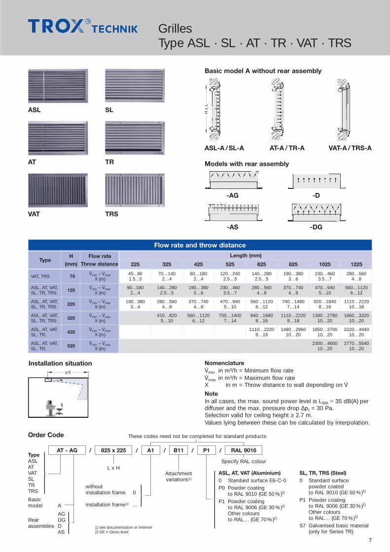
GrillesType ASL · SL · AT · TR · VAT · TRS
ASL SL
Basic model A without rear assembly
ASL-A /SL-A AT-A / TR-A VAT-A / TRS-A
Models with rear assembly
-AG -D
-AS -DG
TR
TRS
AT
VAT
Flow rate and throw distance
H x
L
Order Code
AT - AG 825 x 225 A1 B11 P1 RAL 9016
These codes need not be completed for standard products
/ / / / /TypeASLATVATSLTRTRS
Basicmodel A
AGRear DGassemblies D
AS
L x HAttachmentvariations1)
Specify RAL colour
ASL, AT, VAT (Aluminium)0 Standard surface E6-C-0P0 Powder coating
to RAL 9010 (GE 50 %)2)
P1 Powder coatingto RAL 9006 (GE 30 %)2)
Other coloursto RAL... (GE 70 %)2)
SL, TR, TRS (Steel)0 Standard surface
powder coatedto RAL 9010 (GE 50 %)2)
P1 Powder coatingto RAL 9006 (GE 30 %)2)
Other coloursto RAL... (GE 70 %)2)
S7 Galvanised basic material(only for Series TR)
withoutinstallation frame 0
installation frame1) ...
1) see documentation or Internet2) GE = Gloss level
TypeH Flow rate Length (mm)
(mm) Throw distance 225 325 425 525 625 825 1025 1225
VAT, TRS 75 ‡min – ‡max 45...90 70…140 90…180 120…240 140…280 190…380 230…460 280…560X (m) 1.5...3 2…4 2…4 2.5…5 2.5…5 3…6 3.5…7 4…8
ASL, AT, VAT, 125 ‡min – ‡max 90...180 140…280 190…380 230…460 280…560 370…740 470…940 560…1120SL, TR, TRS X (m) 2…4 2.5…5 3…6 3.5…7 4…8 4…8 5…10 6…12
ASL, AT, VAT, 225 ‡min – ‡max 190...380 280…560 370…740 470…940 560…1120 740…1480 920…1840 1110…2220SL, TR, TRS X (m) 3…4 4…8 4…8 5…10 6…12 7…14 8…16 10…18
ASL, AT, VAT, 325 ‡min – ‡max 410…820 560…1120 700…1400 840…1680 1110…2220 1390…2780 1660…3320SL, TR, TRS X (m) 5…10 6…12 7…14 8…16 9…18 10…20 10…20
ASL, AT, VAT, 425 ‡min – ‡max 1110…2220 1480…2960 1850…3700 2220…4440SL, TR, X (m) 9…18 10…20 10…20 10…20
ASL, AT, VAT, 525 ‡min – ‡max 2300…4600 2770…5540SL, TR, X (m) 10…20 10…20
IEEEEEEOEEEEEEP
IEEEEEEOEEEEEEP
IEEEEEEEEEEEEEEOEEEEEEEEEEEEEP
TEEEEEEEEEEEEEEEEEEEZEEEEEEEEEEEEEEEEEEEEU
Nomenclature‡min in m3/h = Minimum flow rate‡max in m3/h = Maximum flow rateX in m = Throw distance to wall depending on ‡
NoteIn all cases, the max. sound power level is LWA = 35 dB(A) perdiffuser and the max. pressure drop ∆pt = 30 Pa.Selection valid for ceiling height ≥ 2.7 m.Values lying between these can be calculated by interpolation.
Installation situation≥X

8
Flow rate and throw distance
Order Code
TRS - K5 825 x 125 A1 0 P1 RAL 9016
These codes need not be completed for standard products
/ / / / /
Type TRS-KTRS-K5TRS-KATRS-KDTRS-KS
Type TRS-RTRS-R5TRS-RATRS-RDTRS-RS
L x HNot used
Specify RAL colour
0 Standard galvanised surface
P1 Powder coatingto RAL 9006 (GE 30 %)1)
other coloursto RAL... (GE 70 %)1)
1) GE = Gloss level2) only for Series TRS-K
TypeH Flow rate Length (mm)
(mm) Throw distance 225 325 425 525 625 825 1025 1225
TRS-K/TRS-R 75 ‡min – ‡max 45...90 70…140 90…180 120…240 140…280 190…380 230…460 280…560X (m) 1.5...3 2…4 2…4 2.5…5 2.5…5 3…6 3.5…7 4…8
TRS-K/TRS-R 125 ‡min – ‡max 90...180 140…280 190…380 230…460 280…560 370…740 470…940 560…1120X (m) 2…4 2.5…5 3…6 3.5…7 4…8 4…8 5…10 6…12
TRS-K/TRS-R 225 ‡min – ‡max 190...380 280…560 370…740 470…940 560…1120 740…1480 920…1840 1110…2220X (m) 3…4 4…8 4…8 5…10 6…12 7…14 8…16 10…18
TRS-K 325 ‡min – ‡max 410…820 560…1120 700…1400 840…1680 1110…2220 1390…2780 1660…3320X (m) 5…10 6…12 7…14 8…16 9…18 10…20 10…20
TRS-K
TRS-R
RECTANGULAR duct · TRS-K...
CIRCULAR duct · TRS-R...
Nomenclature
‡min in m3/h = Minimum flow rate‡max in m3/h = Maximum flow rateX in m = Throw distance to wall depending on ‡
Note
In all cases, the max. sound power level is LWA = 35 dB(A) perdiffuser and the max. pressure drop is ∆pt = 30 Pa.Selection valid for ceiling height ≥ 2.7 m.
Values lying between these can be calculated by interpolation.
27L+27
H+
27
24L+21
H+
21
A
D
S
5
Installation situation TRS-R≥X
H (mm) D* (mm)
75 150 to 400
125 300 to 900
225 600 to 2400
IEEEEEEEEEEEEEEEEEEEEEEEOEEEEEEEEEEEEEEEEEEEEEEEP
TEEEEEEEEEEZEEEEEEEEEU
Grilles for Installation in DuctsType TRS-K · TRS-R
D
* Pipe diameter
without installation frame 0with installation frame A12)
IEEEEEEEOEEEEEEEP

Dimensions (mm)
9
LVS Z-LVS Installation LVS Installation Z-LVS
Flow rate LVS
Size V.
(m3/h)
100 110
125 180
160 250
200 360
Flow rate Z-LVS
Size V.
(m3/h)
100 100
125 160
160 230
200 280
Nomenclature
‡ in m3/h = Flow rate per air valve
Note
The sound power level is LWA � 40 dB(A) in all cases.
* Dimension “E” must be adjusted according to the linesused.
Type
Supply air Z-LVSExhaust air LVS
Order CodeStandard surface RAL 9010
/ /LVS 125
100125160200Size
G1
IEEEEOEEEEP
TEEEZEEEU
0 without installation frameG1 installation frame (Standard)1)
1) Unless otherwise specified on order, equipment is delivered with installation frame (G1).
50
� D� D
B B
� C � C� E* � E*
50
8 8
Size B ØC ØD ØE*
100 40 99 132 104
125 46 124 162 129
160 54 159 205 164
200 61 199 245 204
Disc ValvesType LVS · Z-LVS

Dimensions (mm)Throw distance and pressure drop
10
DUK DUK-FL2
ØD
4
ØD
3
ØD
5
DUK-V
Installation situation – isotherm –
Size ØD1 ØD3 ØD4 ØD5 L1 L2
100 136 146 98 50 94 78
125 159 169 123 64 112 86
160 225 200 158 82 122 98
200 265 257 198 108 153 117
250 315 302 248 136 187 155
315 400 384 313 174 224 183
400 485 467 398 230 287 208
V.
(m3/h) 75 100 150 250 400 600 800 1000 1250 1500
X (m) X (m) X (m) X (m) X (m) X (m) X (m) X (m) X (m) X (m)Size
∆pt (Pa) ∆pt (Pa) ∆pt (Pa) ∆pt (Pa) ∆pt (Pa) ∆pt (Pa) ∆pt (Pa) ∆pt (Pa) ∆pt (Pa) ∆pt (Pa)
1008 11
50 100
1256 9 11
25 50 100
1605 6 9 12
10 20 40 100
2005 7 9 18
10 15 40 100
2505 7 15 22
5 15 40 90
3155 11 17 23 28
5 15 30 60 90
4008 13 18 23 28 32
5 10 15 25 40 60
X
�
�
�
Occupied zoneNomenclature
X in m = Throw distance∆pt in Pa = Total pressure dropDimension of recess = ØD4 + 15 mm
Note
The combinations, air volumes and size shown in the tableproduce a sound power level:
LWA = 35 dB(A) for axial connectionLWA = 43 dB(A) for lateral connection
1) For attachment without counterpunched holes: Supplementary text necessary for order2) For sizes 100 and 125, construction with actuator not available3) Please indicate onsite duct diameter (ØR) as supplementary text4) GE = Gloss level
Type
Fixed F1)
Adjustable V
Duct connection element KSpigot ADuct connection element for circular ducting R3)
externally mountedwith rotary actuator E1...E3
internally mountedwith linear actuator E4...E6
Size2)Specify RAL colour
0 Standard surface “unfinished”
P0 Powder coatingto RAL 9010 (GE 50 %)4)
P1 Powder coatingto RAL 9006 (GE 30 %)4)
Other coloursto RAL... (GE 70 %)4)
Order Code
DUK - V - K - E1 400 P1 RAL 9016/ / /
IEEOEEP
IEEEEEEOEEEEEEP
IEEEEEEEEOEEEEEEEEP
TEEEEEEEEEEEEEEEZEEEEEEEEEEEEEEU
Jet NozzlesType DUK
L1
ØD
1
ØD
5
9
These codes need not be completed for standard pro-

Dimensions (mm)
11
FB
H
ØR+48
ØR
ØD
�K
Adjustable swirlelement V/H
Trim ring
Dirt trap andadjustable volume control SM/SV
Plastic
Typevertical horizontal
V.
max (m3/h) V.
max (m3/h)
FBK-150 100 50
FBK-200 135 90
Aluminium
Typevertical horizontal
V.
max (m3/h) V.
max (m3/h)
FBA-150 110 60
FBA-200 135 90
Size ØD ØR �K H
150 98 150 200 125
200 123 200 250 150
Sound power level is LWA � 35 dB(A) in all casesTotal pressure drop ∆pt � 40 Pa
600 mm600 mm
∆tZ max = -6K∆tZ max = -10K
Mindestabstand Mindestabstand
Blow-in situation
horizontal(displacement ventilation)
Minimum distancecomfort zone
Minimum distancecomfort zone
vertical(mixed ventilation)
Floor DiffusersType FB
IEEEEEEEOEEEEEEEP
IEEEEEEEEOEEEEEEEEP
1) For orders without trim ring, a spacing ring is provided for technicalperformance reasons and to ensure correct height
2) For orders without adjustable swirl element, the direction of air discharge is vertical
Surface of diffuser core and trim ring:
Die cast and deburred 1
Die cast, deburred,tumble fettled black stove enamel,face skimmed 3
Die cast, deburred,face skimmed 4
Adjustable swirl element2)
for directional controlvertical Vhorizontal H
A Plenum box
Type Type
SM Dirt trap includingadjustable volumecontrol at rear
SV Dirt trap includingadjustable volumecontrol at face
K1) Trim ring
Size
Order Code
FBA - 1 - V - K - SM - A 150/
Surface of diffuser, core and trim ring:
Dusty grey 1similar to RAL 7037Black 2similar to RAL 9005
Adjustable swirl element2)
for directional controlvertical Vhorizontal H
A Plenum box
Standard 0Plastic (PA6)
flame retardant V00(PA6-V0)
SM Dirt trap includingadjustable volumecontrol at rear
SV Dirt trap includingadjustable volumecontrol at front
K1) Trim ring
Size
FBK - 1 - V - K - SM - A 150 V00/ /
IEEOEEP
IEEOEEP
IEEEEEEEEEEEEEEEEEEEEOEEEEEEEEEEEEEEEEEEEEP
TEEEEEEEEEEEEEZEEEEEEEEEEEEU
TEEEEEEEEEEEEEZEEEEEEEEEEEEU

12
Slot DiffusersType VSD15
VSD15-A VSD15-A-Z0 VSD15-D VSD15-D-Z018
2
Ø78
58
15
70 40
40 40
202
58
110 40
Ø78
15
VSD15
Nomenclature
‡ in m3/h = Flow rateX in m = Throw distanceL1 in mm = Length of plenum boxA in m = Distance between 2 diffusersƒH1 in m/s = Time average air velocity between
2 diffusersƒL in m/s = Time average air velocity at the wall
Note
Room height = 3 mƒH1/ ƒL = 0.17 m/s
Sound power level is LWA � 35 dB(A) in all casesPressure drop ∆pt � 30 Pa
If desired, the length of the diffuser face can be greater thanthe length of the plenum box.
Throw distance X (m) · VSD15air discharge horizontal, one direction
L1 (mm)V.
600 700 800 900 1000 1100 1200 1300 1400 150020 1.0 1.0 1.0
30 2.9 1.7 1.2 1.0 1.0
40 4.2 2.9 2.0 1.5 1.0 1.0
50 4.0 2.9 2.2 1.7 1.2
60 4.7 3.8 2.9 2.3 1.9 1.5
70 4.4 3.6 2.9 2.5
80 4.2 3.6
90 4.7
VSD15 air discharge alternating horizontalFlow rate ranges (m3/h)
L1
600 700 800 900 1000 1100 1200 1300 1400 1500‡min ‡max ‡min ‡max ‡min ‡max ‡min ‡max ‡min ‡max ‡min ‡max ‡min ‡max ‡min ‡max ‡min ‡max ‡min ‡max
20 40 20 50 20 50 30 60 30 70 40 80 40 80 50 90 60 100 60 110
Diffuser Layoutair discharge horizontal, one direction air discharge alternating horizontal
0 Standard surfaceVSD15 Black RAL 9005VSD15-Z0 E6-C-0
P0 Powder coatedto RAL 9010 (GE 50 %)1)
P1 Powder coatedto RAL 9006 (GE 30%)1)
Other coloursto RAL … (GE 70%)1)
Order Code
VSD15 - A - M - Z0 - L 900
L1 (mm)
/ / /
Plenum box APlenum box
Dwith lining
Adjustable volume control M
Integral border Z0
Spigot with lip seal L
1) GE = Gloss level2) see documentation or Internet
Not used
Specifycolour
HL Horizontal leftHR Horizontal rightWH Alternating
horizontal (standardconstruction)
0 Standardblackair controlblades
WW whiteaircontrolblades
End caps2)
These codes need not be completed for standard products
0 / / / /P1 RAL 9016 WH WWA9
IEEEEEOEEEEEP
IEEOEEP
TEEEEEEEEEEEEEEEEEEZEEEEEEEEEEEEEEEEEU
TEEEEEEEEEEEZEEEEEEEEEEU
ƒH1 ƒL
A X
1,80
m
ƒL
X
1,80
m1.
80 m
1.80
m

13
IEEEEEEEEOEEEEEEEEP
Type
1
No. of slots 234
See documen- AKtation for DKplenum box AAconstructions AS
DS
Adjustable volume control M
Lip seal L
Front without edge flange 0003)
Integral edge flange B00
Standard surface E6-C-0 0
Powder coating P0to RAL 9010 (GE 50 %)
Powder coating P1to RAL 9006 (GE 30 %)Other coloursto RAL... (GE 70 %)
Horizontal left HL
Horizontal right HR
Alternating horizontal WH
VSD35-1…4-AK VSD35-1…4-DK
Order Code
VSD35 - 1 - AK - M - L 900x98 x y C6 B00 P1 RAL 9016 WH WW/ / / / / / /
These codes need not be completed for standard products
TEEEEEEEEEZEEEEEEEEU
L1 x D x y1)+2) Specify RAL colour 0 blackair controlblades
WW whiteair controlblades
End cape4)
1) with concealed clip fixif y = 0 (Standard),further possible values for y = 30, 55, 80 and 104 mm
2) with clip fixif y = 0 (Standard)further possible values for y = 30, 55, 80, 105 and 129 mm
3) not with concealed slot fixture AS and DS4) see documentation or Internet
øD øD
000
51
P Q
H3(
H3+
y)
H4(
H4+
y)
K1 K2
B00
51(5
1+y)
(51+
y)
IEEOEEP
IEEEEEEEEEEEEEEEOEEEEEEEEEEEEEEEP
Slot DiffusersType VSD35
VSD35
IEEEEEEOEEEEEEP
Nomenclature
‡ in m3/h = Flow rateX in m = Throw distanceL1 in mm = Length of plenum boxA in m = Distance between 2 diffusersƒH1 in m/s = Time average air velocity between
2 diffusersƒL in m/s = Time average air velocity at the wall
Note
Room height = 3 mƒH1 = 0.15 – 0.17 m/sƒL = 0.34 – 0.37 m/s
Sound power level is LWA � 40 dB(A) in all casesPressure drop ∆pt � 30 Pa
If required, the length of the diffuser face can be greater thanthe length of the plenum box.
Dimensions (mm)No. of K1 K2 H1
1) H21) H3
2) H42) P3) Q ØDslots
1 100 138 228 248 202 223 35 55 98123
2 138 176 258 278 233 253 62 82 123138
3 176 214 276 296 251 271 89 109 138158
4 214 254 308 328 283 303 116 136 158198
Diffuser layoutair discharge horizontal, one direction air discharge alternating horizontal
ƒH1 ƒL
A X
1,80
m
ƒL
X
1,80
m1.
80 m
1.80
m

14
Slot DiffusersType VSD35
Throw distance X (m) · VSD35-1air discharge horizontal, one direction
L1 (mm)V.
600 750 900 1050 1200 1350 1500 1650 1800 195040 2.250 4.2 2.260 6.4 3.7 2.270 8.2 5.4 3.4 2.280 7.6 4.9 3.2 2.290 8.7 6.4 4.5 3.1 2.2
100 7.2 5.7 4.1 3.0 2.2110 7.2 5.3 3.9 2.9 2.2120 7.7 6.5 4.9 3.7 2.9 2.2140 8.2 7.1 5.4 4.3 3.4 2.8160 8.5 7.6 6.0 4.9 3.9180 8.7 8.1 6.4 5.4200 8.8 8.1 6.9220 7.5
Throw distance X (m) · VSD35-2air discharge horizontal, one direction
L1 (mm)V.
600 750 900 1050 1200 1350 1500 1650 1800 195080 5.5
100 8.3 5.5 3.2120 7.5 5.5 3.2140 7.1 5.5 3.4160 6.7 5.5 3.6180 8.8 6.4 5.5 3.7200 8.3 6.2 5.5 3.8220 7.8 6.1 5.5 3.9240 7.5 5.9 5.5 3.9260 7.3 5.8 5.5280 8.7 7.1 5.8300 8.3 6.9320 8.0
Throw distance X (m) · VSD35-3air discharge horizontal, one direction
L1 (mm)V.
600 750 900 1050 1200 1350 1500 1650 1800 1950100 5.1120 7.9 4.7140 6.7 4.1160 6.0180 7.9 5.4200 7.0 5.1220 8.8 6.4 4.8240 7.9 6.0260 7.2 5.6280 8.5 6.7 5.3300 7.9 6.3 5.1320 7.3 6.0 4.9340 8.4 6.9 5.7360 7.9 6.5380 7.3400 8.3
Throw distance X (m) · VSD35-4air discharge horizontal, one direction
L1 (mm)V.
600 750 900 1050 1200 1350 1500 1650 1800 1950120 5.6140 8.1 4.8160 6.6180 8.7 5.6200 8.2 5.0220 8.7 6.4 4.5240 7.8 5.6260 8.8 6.9 5.2280 8.1 6.1 4.8300 8.4 7.2 5.6 4.5320 8.4 6.6 5.2340 8.6 7.6 6.1 4.9360 8.7 6.9 5.6 4.7380 7.9 6.4 5.3400 8.8 7.2 6.0420 8.1 6.7440 7.5460 8.3
VSD35-1…4-AA VSD35-1…4-AS VSD35-1…4-DS
H1(
H1+
y)
K1
øD
76
Q
(76+
y)
B00
øD76
(76+
y)
K2
H2(
H2+
y)
B00Q
VSD35
VSD35 air discharge alternating horizontalNo. ofslots“n”
Air volume ranges (m3/h)L1 (mm)
600 750 900 1050 1200 1350 1500 1650 1800 1950‡min ‡max ‡min ‡max ‡min ‡max ‡min ‡max ‡min ‡max ‡min ‡max ‡min ‡max ‡min ‡max ‡min ‡max ‡min ‡max
1 40 70 50 90 60 110 70 120 80 140 90 160 100 180 110 200 120 220 140 240
2 80 100 100 120 120 160 140 180 160 220 180 240 200 260 220 300 240 320 260 340
3 100 120 140 160 160 180 180 220 200 240 220 280 260 320 280 340 300 380 320 420
4 120 140 140 180 180 220 200 260 220 300 240 340 280 360 300 400 340 440 360 480
000
K1
H3
(H3
+ y
) øD55
(55
+ y
)
P

15
VSD50-1…2-AK VSD50-1…2-DK
K2
Q
B00
H4
(H4
+ y
) øD55
(55
+ y
)
K1
000
H3
(H3
+ y
)
P
øD55
(55
+ y
)
IEEEEEEEEOEEEEEEEEP
IEEOEEP
Type
No. of slots 12
For plenum AKbox construc- DKtions, see AAdocumentation AS
DS
Adjustable volume control M
Lip seal L
Without edge flange 0003)
Integrated edge flange B00
Standard surface E6-C-0 0
Powder coating P0to RAL 9010 (GE 50 %)
Powder coating P1to RAL 9006 (GE 30 %)Other coloursto RAL... (GE 70 %)
Horizontal left HL
Horizontal right HR
Alternating horizontal WH
Order Code
VSD50 - 1 - AK - M - L 900x123 x y C6 B00 P1 RAL 9016 WH WW/ / / / / / /
These codes need not be completed for standard products
TEEEEEEEEEZEEEEEEEEU
L1 x D x y1)+2) Specify RAL colour 0 blackair controlblades
WW whiteair controlblades
End caps4)
1) with concealed screw fixtureif y = 0 (Standard),further possible values for y = 30, 55, 80 and 104 mm
2) with clip fixif y = 0 (Standard)further possible values for y = 30, 55, 80, 105 and 129 mm
3) not with concealed slot fixture AS and DS4) see documentation or Internet
IEEOEEP
IEEEEEEEEEEEEEEEOEEEEEEEEEEEEEEEP
Slot DiffusersType VSD50
VSD50
Nomenclature
‡ in m3/h = Flow rateX in m = Throw distanceL1 in mm = Length of plenum boxA in m = Distance between 2 diffusersƒH1 in m/s = Time average air velocity between
2 diffusersƒL in m/s = Time average air velocity at the wall
Note
Room height = 3 mƒH1 = 0.15 – 0.17 m/sƒL = 0.34 – 0.37 m/s
Sound power level is LWA � 40 dB(A) in all casesPressure drop ∆pt � 30 Pa
If required, the length of the diffuser face can be greater thanthe length of the plenum box.
Dimensions (mm)No. of K1 K2 H1
1) H21) H3
2) H42) P3) Q ØDslots
1 100 138 267 287 242 262 50 70 123158
2 138 176 307 327 282 302 92 112 158198
Diffuser Layoutair discharge horizontal, one direction air discharge alternating horizontal
ƒH1 ƒL
A X
1,80
m
ƒL
X
1,80
m1.
80 m
1.80
m

16
Slot DiffusersType VSD50
VSD50-1…2-AA VSD50-1…2-AS VSD50-1…2-DSVSD50
H1(
H1+
y)
K1
øD
76(7
6+y)
B00000
øD76
(76+
y)
K2
H2(
H2+
y)
B00
K1
H3
(H3
+ y
) øD55
(55
+ y
)
P Q Q
Throw distance X (m) · VSD50-1air discharge horizontal, one direction
L1 (mm)V.
600 750 900 1050 1200 1350 1500 1650 1800 195040 3.050 3.0 3.060 4.0 3.0 3.070 5.5 3.4 3.0 3.080 7.1 4.6 3.2 3.0 3.090 5.8 4.0 3.0 3.0 3.0
100 7.1 5.0 3.6 3.0 3.0 3.0110 8.7 6.0 4.4 3.5 3.0 3.0 3.0120 7.1 5.3 4.0 3.2 3.0 3.0 3.0140 7.1 5.5 4.3 3.5 3.0 3.0 3.0160 7.1 5.7 4.6 3.7 3.2 3.0180 7.1 5.8 4.8 4.0 3.3200 8.8 7.1 5.9 5.0 4.3220 8.7 7.1 6.0 5.2240 8.5 7.1 6.1260 8.3 7.1280 8.3
Throw distance X (m) · VSD50-2air discharge horizontal, one direction
L1 (mm)V.
600 750 900 1050 1200 1350 1500 1650 1800 195080 3.090 5.5
100 6.8 3.0110 8.1 5.3 3.0120 6.2 3.0 3.0140 8.4 5.9 3.0160 7.7 5.6 3.0180 7.1 5.5 3.0200 8.7 6.8 5.3 3.0220 8.1 6.5 5.3 3.0240 7.7 6.2 5.1 3.0260 7.3 6.1 5.0280 8.4 7.0 5.9 3.0300 8.0 6.8 5.8320 7.7 6.5340 8.6 7.4360 8.3
VSD50 air discharge alternating horizontalNo. ofslots“n”
Flow rate ranges (m3/h)L1 (mm)
600 750 900 1050 1200 1350 1500 1650 1800 1950‡min ‡max ‡min ‡max ‡min ‡max ‡min ‡max ‡min ‡max ‡min ‡max ‡min ‡max ‡min ‡max ‡min ‡max ‡min ‡max
1 40 90 50 100 60 120 70 140 80 180 90 200 100 200 110 240 120 260 140 280
2 90 120 110 140 140 180 160 220 180 240 200 280 220 300 240 320 260 360 300 380

17
Minimumflow rate
Dimensions (mm)
Flow rate (m3/h) –Arrangement square/rectangular
square Qcircular R
Nozzle D
Collar K
Top entry plenum US
Plenum box A
SizeType Specify RAL colour
0 Standard surfacepowder coatedto RAL 9010 (GE 50 %)1)
P1 Powder coatingto RAL 9006 (GE 30 %)1)
Other coloursto RAL... (GE 70 %)1)
RFD-Q RFD-Q/R-D-A RFD-Q/R-D-K RFD-Q/R-D-US
Order Code RFD - Q - D - A 400 0 0 P1 RAL 9016/ / / / /
1) GE = Gloss level
Flow rate (m3/h) – Arrangement single-row
SizeA (m)
0 1.2 1.8 2.4 3.0 3.6 4.2125 126 120 100 105 115 125 125160 180 160 140 140 150 170 180200 250 250 170 170 190 210 240250 395 395 210 210 220 240 280315 610 610 310 310 330 360 410400 820 870 350 370 410 470 520
Diffuser layout
Size ØA ØD H2 U2 U4 �Q2 ØR2 �K
125 123 98 284 75 153 198 200 216160 158 123 309 78 158 248 250 266200 198 158 339 78 161 248 300 290250 248 198 384 75 166 298 350 476315 313 248 444 88 183 398 450 567400 398 313 509 88 193 498 580 615
B≥1
/2B
≥1/2AA A
Nomenclature
‡ in m3/h = Flow rate‡min in m3/h = Flow rate, minimumA, B in m = Distance between two diffusers
Note
In all cases, the sound power level is LWA � 40 dB(A) perdiffuser and the pressure drop ∆pt � 45 Pa.
Selection valid for ceiling height 2.7 m to 3 m.
IEEOEEP
TEEEEEEEEEEEEZEEEEEEEEEEEEU
H2
� K
ØD
ØR2� Q2
ØR2�Q2
ØR2�Q2
ØA
ØD
U2
U4
40
These codes need not be completed for standard products
IEEEEEEOEEEEEEP
Swirl DiffusersType RFD
SizeB A (m)
(m) 1.2 1.8 2.4 3.0 3.6 4.2125 55 55 65 80 90 105160 75 75 90 105 125 140200
2.4100 100 115 135 160 170
250 115 115 125 165 185 205315 185 230 270 300400 290 330 370125 75 75 80 85 100 115160 100 100 105 110 130 150200
3.0125 125 135 145 170 190
250 155 155 165 165 200 220315 220 220 240 240 300 320400 290 260 370 410125 95 90 95 100 115 125160 130 120 125 125 150 170200
3.6160 150 160 170 190 210
250 200 190 190 200 210 240315 280 270 280 290 290 360400 310 310 330 350 370 480125 120 105 105 115 125 125160 160 140 140 150 170 180200
4.2200 170 170 190 210 250
250 240 210 210 220 240 260315 350 310 310 330 360 380400 370 350 380 420 480 480
Size V.
min
125 35160 50200 60250 110315 180400 250

18
Dimensions (mm)
DCS-P DCS-P-...-A resp. -AK DCS-P-...-K DCS-P-...-US
Flow rate (m3/h) – Arrangement single-row
SizeA (m)
0 1.2 1.8 2.4 3.0 3.6 4.2125 90 90 90 90 90 90 90160 140 140 120 120 130 140 140200 210 180 150 150 170 190 210250 290 220 190 190 210 240 280315 440 310 270 270 290 350 400400 650 310 290 310 360 400 430
Diffuser layoutFlow rate (m3/h) –Arrangement square/rectangular
B≥1
/2B
≥1/2AA A
Nomenclature
‡ in m3/h = Flow rate‡min in m3/h = Flow rate, minimumA, B in m = Distance between two diffusers
Note
The sound power level is LWA � 40 dB(A) per diffuser in allcases and the pressure drop ∆pt � 45 Pa.
Selection valid for ceiling height = 2.7...3 m.
� 593 (� 598, � 623)
H2
H1
�D
8
� K11 11
� 593 (� 598, � 623)
H2
8
�A
�D
8
H3
� 593 (� 598, � 623)
Swirl Diffusers with perforated sheet facingType DCS
SizeB A (m)
(m) 1.2 1.8 2.4 3.0 3.6 4.2125 60 60 65 70 80 90160 90 90 90 95 105 120200
2.4110 110 115 115 135 150
250 135 135 135 145 165 185315 200 200 210 210 230 260400 250 310125 70 70 70 80 90 90160 90 90 95 110 120 130200
3.0110 110 115 150 150 170
250 135 140 140 170 180 210315 200 200 210 250 250 290400 280 360125 80 75 80 90 90 90160 110 105 105 110 115 140200
3.6140 135 135 140 150 190
250 170 160 170 170 170 240315 240 230 230 250 250 330400 280 250 250 280 280 400125 90 90 90 90 90 90160 140 120 120 135 140 140200
4.2170 150 150 170 190 200
250 210 190 190 210 240 240315 290 260 260 290 340 340400 310 290 310 360 400 435
Size ØA ØD H1 H2 H3 �K
125 123 98 156 76 154 180160 158 123 180 79 159 215200 198 158 215 79 162 255250 248 198 255 76 167 305315 313 248 305 89 184 370400 398 313 361 89 194 454
Minimumflow rate
Size V.
min
125 35160 50200 60250 110315 180400 250
Face plate:perforated Pnon-perforated Nwith discharge nozzle ring C
T-box:visible Vhidden H
Collar KTop entry plenum USPlenum box APlenum box AKwith insulation
Size
Type Specify RAL colour
0 Standard surfacepowder coatedto RAL 9010 (GE 50 %)1)
P1 Powder coatingto RAL 9006 (GE 30 %)1)
Other coloursto RAL... (GE 70 %)1)
Order Code DCS - P - V - AK 5932) x 315 P1 RAL 9016/ / /
1) GE = Gloss level2) 593 x ... with face plates ...-V
598 x ... and 623 x ... with face plates ...-H
IEEOEEP
TEEEEEEEEEEEEZEEEEEEEEEEEEUIEEEEEEEEEOEEEEEEEEEP
IEEEEOEEEEP
These codes need not be completed for standard products
19
Minimumflow rate
Type
square Qcircular R
supply air Zexhaust air A
vertical connection Vhorizontal connection H
Adjustable volume control Mwith single blade
L Spigot withlip seal
SizeSpecify RAL colour
0 Standard surfacepowder coatedto RAL 9010 (GE 50 %)1)
P1 Powder coatingto RAL 9006 (GE 30 %)1)
Other coloursto RAL... (GE 70 %)1)
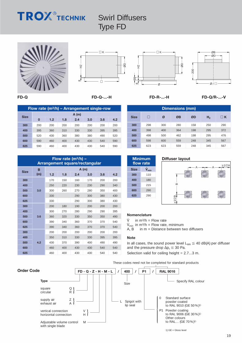
FD-Q FD-Q-...-H FD-R-...-H FD-Q/R-...-V
Order Code FD - Q - Z - H - M - L 400 P1 RAL 9016/ / /
1) GE = Gloss level
Flow rate (m3/h) – Arrangement single-row Dimensions (mm)
SizeA (m)
0 1.2 1.8 2.4 3.0 3.6 4.2
300 200 200 200 200 200 200 200
400 395 360 310 330 330 395 395
500 520 430 360 380 380 490 520
600 590 460 400 430 430 540 590
625 590 460 400 430 430 540 590
Diffuser layoutFlow rate (m3/h) –Arrangement square/rectangular
SizeB A (m)
(m) 1.2 1.8 2.4 3.0 3.6 4.2
300 170 150 160 170 200 200
400 250 220 230 230 290 340
500 3.0 300 260 270 280 350 400
600 330 290 300 380 430
625 330 290 300 380 430
300 200 180 190 200 200 200
400 300 270 280 290 290 395
500 3.6 360 320 330 350 350 490
600 390 340 360 370 370 540
625 390 340 360 370 370 540
300 200 200 200 200 200 200
400 350 310 330 330 395 395
500 4.2 430 370 390 400 490 490
600 460 400 430 430 540 540
625 460 400 430 430 540 540
B≥1
/2B
≥1/2AA A
Size V.
min
300 110
400 180
500 215
600 290
625 290
Nomenclature
‡ in m3/h = Flow rate‡min in m3/h = Flow rate, minimumA, B in m = Distance between two diffusers
Note
In all cases, the sound power level LWA � 40 dB(A) per diffuserand the pressure drop ∆pt � 30 Pa.
Selection valid for ceiling height = 2.7...3 m.
ØD
H2
8
� K
�
ØD
H2
835
� K
Ø
200
ØBØD
Ø / �
IEEOEEP
IEEOEEP
IEEOEEP
TEEEEEEEEEEEEEEZEEEEEEEEEEEEEEU
Swirl DiffusersType FD
Size � Ø ØB ØD H2 � K
300 298 300 280 158 250 290
400 398 400 364 198 295 372
500 498 500 462 198 295 476
600 598 600 559 248 345 567
625 623 623 559 248 345 567
These codes need not be completed for standard products

20
Minimumflow rate
Dimensions (mm)
TDF-SA-Q-... TDF-SA-Q-...-H TDF-SA-R-...-H TDF-SA-Q/R-...-V
Flow rate (m3/h) – Arrangement single-row
SizeA (m)
0 1.2 1.8 2.4 3.0 3.6 4.2
300 230 230 230 230 230 230 230
400 430 260 260 260 260 260 280
500 510 390 400 400 400 400 420
600 650 470 470 470 470 470 500
625 650 470 470 470 470 470 500
Diffuser layoutFlow rate (m3/h) –Arrangement square/rectangular
SizeB A (m)
(m) 1.2 1.8 2.4 3.0 3.6 4.2
300 180 180 180 180 190 230
400 230 230 230 230 240 260
500 3.0 290 290 290 290 340 390
600 360 360 360 360 410 470
625 360 360 360 360 410 470
300 200 200 200 200 200 230
400 240 240 250 270 270 270
500 3.6 340 330 330 330 340 400
600 400 380 380 380 400 470
625 400 380 380 380 400 470
300 230 230 230 230 230 230
400 260 270 260 270 270 350
500 4.2 390 390 390 390 390 440
600 470 470 470 470 470 500
625 470 470 470 470 470 500
ØD
H2
8
� K
�
ØD
H2
8
� K
Ø
200
ØBØD
Ø / �
B≥1
/2B
≥1/2AA A
Nomenclature
‡ in m3/h = Flow rate‡min in m3/h = Flow rate, minimumA, B in m = Distance between two diffusers
Note
In all cases, the sound power level is LWA � 40 dB(A) perdiffuser and the pressure drop ∆pt � 40 Pa.
Selection valid for ceiling height = 2.7...3 m.
Type
square Qcircular R
supply air Zexhaust air A
Adjustable volume control Mwith single blade
Spigot with lip seal L
SizeSpecify RAL colour
0 Standard surfacepowder coatedto RAL 9010 (GE 50 %)1)
P1 Powder coatingto RAL 9006 (GE 30 %)1)
Other coloursto RAL... (GE 70 %)1)
Order Code TDF-SA - Q - Z - M - L 400 P1 RAL 9016/ / /
1) GE = Gloss level
IEEOEEP
IEEOEEP
IEEOEEP
TEEEEEEEEEEEEEEZEEEEEEEEEEEEEU
Swirl DiffusersType TDF-SA
Size � Ø ØB ØD H2 � K
300 298 300 280 158 250 290
400 398 400 364 198 295 372
500 498 500 462 198 295 476
600 598 600 559 248 345 567
625 623 623 559 248 345 587
Size V.
min
300 110
400 180
500 215
600 290
625 290
These codes need not be completed for standard products

21
Minimumflow rate
Dimensions (mm)
Type
square Qcircular R
supply air Zexhaust air A
vertical connection Vhorizontal connection H
Adjustable volume control Mwith single blade
Spigot with lip seal L
Size xNo. of
air controlblades
Specify RAL colour
* Size: 600 x 48 / 625 x 54
0 Standard surfacepowder coatedto RAL 9010 (GE 50 %)1)
P1 Powder coatingto RAL 9006 (GE 30 %)1)
Other coloursto RAL... (GE 70 %)1)
0 Supply air: black air control bladesExhaust air: no air control blades
Q11 Exhaust air: black air control blades
Q21 Supply air: white air control bladesExhaust air: white air control blades
VDW-Q VDW-Q-...-H VDW-R-...-H VDW-Q/R-...-V
Order Code VDW - R - Z - V - M - L 600 x 24 Q21 P1 RAL 9016/ / / /
1) GE = Gloss level
Flow rate (m3/h) – Arrangement single-row
Diffuser layoutFlow rate (m3/h) –Arrangement square/rectangular
SizeB A (m)
(m) 1.2 1.8 2.4 3.0 3.6 4.2300 x 8 155 140 150 160 190 210400 x 16 200 200 210 230 290 330500 x 24 240 220 230 300 300 330600 x 24 3.0 290 290 310 350 420 490600 x 48 360 360 360 360 450 530625 x 24 290 290 310 350 420 490625 x 54 510 590300 x 8 180 170 180 190 230 250400 x 16 240 240 250 290 320 390500 x 24 290 270 290 290 420 450600 x 24 3.6 340 340 380 420 500 580600 x 48 420 390 420 450 500 650625 x 24 340 340 380 420 500 580625 x 54 460 500 560 710300 x 8 210 190 200 210 250 250400 x 16 280 270 300 320 390 390500 x 24 350 330 340 340 450 460600 x 24 4.2 400 400 430 480 570 660600 x 48 500 470 500 530 670 780625 x 24 400 400 430 480 570 660625 x 54 540 500 540 590 710 820
B≥1
/2B
≥1/2AA A
Nomenclature
‡ in m3/h = Flow rate‡min in m3/h = Flow rate, minimumA, B in m = Distance between two diffusers
Note
In all cases, the sound power level is LWA � 40 dB(A) perdiffuser and the pressure drop ∆pt � 40 Pa.
Selection valid for ceiling height = 2.7...3 m.
ØD
H2
8
� K
�
ØD
H2
835
� K
Ø
200
(300
)*
ØBØD
Ø / �
IEEOEEP
IEEOEEP
IEEOEEP
TEEEEEEEEEEEEEEZEEEEEEEEEEEEEEU
TEEEEEEEEEEZEEEEEEEEEU
Swirl DiffusersType VDW
SizeA (m)
0 1.2 1.8 2.4 3.0 3.6 4.2300 x 8 250 210 190 200 210 250 250400 x 16 390 280 280 300 310 390 390500 x 24 460 350 330 340 340 430 460600 x 24 660 400 400 430 460 570 660600 x 48 820 500 450 500 500 650 760625 x 24 660 400 400 430 460 570 660625 x 54 830 530 500 540 560 710 840
Size � Ø ØB ØD H2 � K
300 x 8 298 300 280 158 250 290
400 x 16 398 400 364 198 295 372
500 x 24 498 500 462 198 295 476
600 x 24 598 600 559 248 345 567
600 x 48 598 600 580 248 345 590
625 x 54 623 – 605 248 345 615
Size V.
min
300 x 8 54
400 x 16 108
500 x 24 144
600 x 24 216
600 x 48 360
625 x 54 432
These codes need not be completed for standard products

22
Minimumflow rate
Dimensions (mm)
TDV-SA-Q-... TDV-SA-Q-...-H TDV-SA-R-...-H TDV-SA-Q/R-...-V
Flow rate (m3/h) – Arrangement single-row
SizeA (m)
0 1.2 1.8 2.4 3.0 3.6 4.2
300 270 270 270 270 270 270 270
400 420 340 340 340 340 340 370
500 570 420 420 420 420 420 440
600 800 490 490 490 490 500 530
625 800 490 490 490 490 500 530
Diffuser layoutFlow rate (m3/h) –Arrangement square/rectangular
ØD
H2
8
� K
�
ØD
H2
8
� K
Ø
200
ØBØD
Ø / �
B≥1
/2B
≥1/2AA A
Nomenclature
‡ in m3/h = Flow rate‡min in m3/h = Flow rate, minimumA, B in m = Distance between two diffusers
Note
In all cases, the sound power level is LWA � 40 dB(A) perdiffuser and the pressure drop ∆pt � 42 Pa.
Selection valid for ceiling height = 2.7...3 m.
Type
square Qcircular R
supply air Zexhaust air A
vertical connection Vhorizontal connection H
Adjustable volume control Mwith single blade
Spigot with lip seal L
Size
Specify RAL colour
0 Standard surfacepowder coatedto RAL 9010 (GE 50 %)1)
P1 Powder coatingto RAL 9006 (GE 30 %)1)
Other coloursto RAL... (GE 70 %)1)
0 Supply air: black air control bladesExhaust air: no air control blades
Q11 Exhaust air: black air control blades
Q21 Supply air: white air control bladesExhaust air: white air control blades
Order Code TDV-SA - Q - Z - V - M - L 400 Q21 P1 RAL 9016/ / / /
1) GE = Gloss level
IEEOEEP
IEEOEEP
IEEOEEP
TEEEEEEEEEEEEEEZEEEEEEEEEEEEEU
TEEEEEEEEEEZEEEEEEEEEU
Swirl DiffusersType TDV-SA
SizeB A (m)
(m) 1.2 1.8 2.4 3.0 3.6 4.2
300 190 190 190 170 230 270
400 250 250 250 250 300 340
500 3.0 300 300 300 300 360 420
600 360 360 360 360 430 490
625 360 360 360 360 430 490
300 220 220 220 220 220 270
400 300 300 300 300 310 340
500 3.6 360 360 360 330 370 420
600 430 430 430 400 430 500
625 430 430 430 400 430 500
300 270 270 270 270 270 270
400 340 340 340 340 340 390
500 4.2 420 420 420 420 420 470
600 490 490 490 490 500 540
625 490 490 490 490 500 540
Size � Ø ØB ØD H2 � K
300 298 300 280 158 250 290
400 398 400 364 198 295 372
500 498 500 462 198 295 476
600 598 600 559 248 345 567
625 623 623 559 248 345 567
Size V.
min
300 110
400 180
500 215
600 340
625 340
These codes need not be completed for standard products

23
Swirl DiffusersType VDL
Discharge ring without flange ADischarge ring with flange B
horizontal connection Hvertical connection Vdiffuser face only F
with lip seal L1)
Diffuser face not removable N1)
Diffuser face removable D1)
with square collar K2)
with protection grid S2)
M manually adjustableE1 electric actuator, 230 V, 50 HzE2 electric actuator, 24 V, 50 HzE3 electric actuator, 24 V, 50 Hz, 2...10 VX fixed blades (for horizontal air discharge only)
Order code These codes need not be completed for standard products
/ / / / /VDL - B - H - L - D - S - E3 RAL 9016400 0 0 P1
Specify colour
0 Standard surfacepowder coatedto RAL 9010 (GE 50 %)3)
P1 Powder coatingto RAL 9006 (GE 30 %)3)
Other coloursto RAL.. . (GE 70 %)3)
Size
IEEOEEP
IEEEEEEEEEEEEEEOEEEEEEEEEEEEEEEPNot used
1) only in combination with constructions H and V2) only in combination with discharge ring B3) GE = Gloss level
IEEEEOEEEEP
IEEOEEP
IEEOEEP
IEEEEEEEEEOEEEEEEEEEP
VDL VDL-...-F VDL-...-V VDL-...-H
H1
ØD2ØD3
ØD1
H2(
X)H
3(M
)
A
H4
ØD2
ØD3
ØD1
A
ØD2ØD3
H8
ØD
5
H6
H7
H5
�K
ØD465
A
Dimensions (mm)Size A ØD1 ØD2 ØD3 ØD4 ØD5 H1 H2 H3 H4 H5 H6 H7 H8 �K315 42 313 464 381 317 248 145 92 80 215 474 150 282 290 435400 45 398 567 468 402 313 157 101 89 236 581 168 368 351 500630 51 628 871 700 628 398 204 117 105 367 812 293 468 526 750800 55 798 1077 871 798 498 229 123 111 538 1081 458 568 741 1000
Technical Data Diffuser layout
Nomenclature‡ in m3/h = Flow rate‡min in m3/h = Flow rate, minimumH in m = Room heightH1 in m = Distance between discharge level and occupied zoneH1 in m = jet penetration distance, vertical discharge,
in heating operationAmin, B in m = Distance between 2 diffusersXmin in m = Distance from wallƒH1 in m/s = time average air velocity between 2 diffusersƒL in m/s = time average air velocity at the wallLWA in dB(A) = Sound power level∆pt in Pa = Pressure drop
NoteB = > 5 mƒH1 = < 0.2 m/sƒL = 0.4 m/sXmin = 2 m
Selection valid for ceiling height 3.8 m to 6.8 m
VDL-...-H Heating operation Cooling operationH = 3.8 H > 6.8
Size LWA V.
∆pt H1 Amin Amin
40 400 29 1.2 2.0 2.0315 50 550 52 2.0 2.0 2.0
60 750 95 3.0 2.0 2.040 800 37 2.5 2.0 2.0
400 50 1100 75 3.5 2.3 2.060 1550 140 5.0 3.5 2.040 1500 30 2.8 2.5 2.0
630 50 2100 60 5.0 4.0 2.060 3250 125 7.5 5.3 2.740 2000 23 3.0 2.7 2.0
800 50 2750 47 5.0 4.5 2.160 3750 90 6.5 5.0 2.7
1.80 m
Minimumflow rate
Size V.
min
315 252
400 450
630 828
800 1152

24
Ceiling DiffusersType VDR
VDR-...-V VDR-...-H
�KØB2
H6
H5 H
1
H2
H8
H3
ØD
ØD
ØR ØR
45VDR
These codes need not be completed for standard products
/ / / / /
vertical connection V horizontal connection H
230 V, 50 Hz, E1Open-Closed control
24 V, 50 Hz, E2Open-Closed control
24 V�, 2...10 V-, E3constant control
IEEOEEP
IEEEEEEEEEEEEEEOEEEEEEEEEEEEEEP
VDR-V-E1 630 0 0 P1 RAL 9016
Specify colour
0 Standard surfacepowder coatedto RAL 9010 (GE 50 %)1)
P1 Powder coatingto RAL 9006 (GE 30 %)1)
Other coloursto RAL... (GE 70 %)1)
Not used
Size
1) GE = Gloss level
IEEEEEEEEEEEOEEEEEEEEEEEP
Technical DataVDR-...-H Heating operation Cooling operation
H=3.8 H>6.8Size LWA V
.∆pt H1 (+10 K)
Amin Amin
31540 782 40 4.5 3.0 2.050 1080 70 7.0 4.5 2.3
40040 1152 35 5.5 4.0 2.050 1584 65 6.0 6.0 3.0
63040 2232 40 6.0 5.5 2.550 2952 70 10.0 7.0 3.2
80040 3060 30 10.0 6.0 3.050 4500 65 12.0 8.3 4.0
Dimensions (mm)Size ØB2 ØD H1 H2 H3 H5 H6 H8 �K ØR
315 314 248 570 457 301 427 270 350 415 450400 399 313 667 537 348 550 375 425 500 570630 629 398 807 632 401 670 450 490 750 870800 799 498 965 754 473 790 535 590 920 1070
Order Code
Nomenclature‡ in m3/h = Flow rateH in m = Room heightH1 in m = Distance between discharge level and occupied zoneH1 in m = vertical penetration depth of air current in heating
operationAmin, B in m = Distance between 2 diffusersXmin in m = Distance from wallƒH1 in m/s = time average air velocity between 2 diffusersƒL in m/s = time average air velocity at the wallLWA in dB(A) = Sound power level∆pt in Pa = Pressure drop
NoteB = > 5 mƒH1 = < 0.2 m/sƒL = 0.4 m/sXmin = 3 m
Selection valid for ceiling height 3.8 m to 6.8 m
Diffuser layout
1.80 m
Minimumflow rate
Size V.
min
315 640
400 910
630 1770
800 2510

25
Minimumflow rate
Dimensions (mm)
DLQ DLQ-AK
Diffuser layoutA
≥A
/2
A≥A/2
Nomenclature
‡ in m3/h = Flow rate‡min in m3/h = Flow rate, minimumA in m = Minimum distance between two diffusers
Note
In all cases, the sound power level is LWA � 40 dB(A) perdiffuser and the pressure drop ∆pt � 28 Pa.
Selection valid for ceiling height = 2.7...3 m.
�
H
� K 50
ØD
8
Type
Diffuser face Awith plenum box AK
Adjustable volume control M1)
Spigot with lip seal L1)
Size Not usedSpecify RAL colour
0 Standard surfacepowder coatedto RAL 9010 (GE 50 %)2)
P1 Powder coatingto RAL 9006 (GE 30 %)2)
Other coloursto RAL... (GE 70 %)2)
Order Code
DLQ - AK - M - L 500 0 0 P1 RAL 9016/ / / / /
1) Only for model ...-AK2) GE = Gloss level
IEEOEEP
TEEEEEEEEEEEEEEZEEEEEEEEEEEEEEU
These codes need not be completed for standard products
Ceiling DiffusersType DLQ
Minimum distance between two diffusers (A)
Size � ØD H �K
250 248 158 262 216
300 298 158 262 266
400 398 198 307 372
500 498 248 357 476
600 598 313 420 567
625 623 313 420 567
Size V.
min
250 110
300 145
400 280
500 485
600 820
625 820
SizeFlow rate V
.(m3/h)
110 145 180 280 420 485 540 720 820 900 1080 1200 1400 1800
250 2.0 2.5 3.2 4.7
300 2.0 2.2 3.3 4.8
400 2.4 3.4 4.2 4.8 5.7 6.4
500 3.0 3.5 4.6 4.8 5.3 6.3 6.5 7.5
600 4.0 4.6 5.5 6.5 6.5 8.0
625 4.0 4.6 5.5 6.5 6.5 8.0

26
Minimumflow rate
Dimensions (mm)
DLQL DLQL-P-H DLQL-P-V DLQL-K-...
Diffuser layout
�2
H1
7
�K
ØD
11�2
�KØD
H2
�1
27
A≥
A/2
A ≥ A/2
Nomenclature
‡ in m3/h = Flow rate‡min in m3/h = Flow rate, minimumA in m = Minimum distance between two diffusers
Note
In all cases, the sound power level is LWA � 40 dB(A) perdiffuser and the pressure drop ∆pt 25 Pa.
Selection valid for ceiling height = 2.7...3 m.
Type
Cover border Q(face width 27 mm)
Flush border P(face width 11 mm)
vertical connection Vhorizontal connection H
Acoustic lining D1)
Adjustable volume control M1)
L Spigot with lip seal
Size Not usedSpecify RAL colour
0 Standard surfacepowder coatedto RAL 9010 (GE 50 %)2)
P1 Powder coatingto RAL 9006 (GE 30 %)2)
Other coloursto RAL... (GE 70 %)2)
Order Code
DLQL - P - H - D - M - L 500 0 0 P1 RAL 9016/ / / / /
1) only possible with horizontal connection2) GE = Gloss level
IEEOEEP
TEEEEEEEEEEEEZEEEEEEEEEEEEU
These codes need not be completed for standard products
IEEEEEEOEEEEEEP
Ceiling Diffusers with perforated sheet facingType DLQL
Size �1 �2 H1 H2 ØD �K
300 330 298 280 50 158 243
400 430 398 320 65 198 343
500 530 498 370 65 248 443
600 630 598 435 80 313 543
625 – 623 435 80 313 568
Size V.
min
300 150
400 250
500 300
600 550
625 550
Minimum distance between two diffusers (A)
SizeFlow rate V
.(m3/h)
150 175 200 250 300 350 400 450 500 550 600 650 700
300 1.6 2.0 2.4
400 2.2 2.6 2.8
500 2.0 2.4 2.6 3.0 3.2 3.6 4.0
600 3.0 3.2 3.6 4.0
625 3.0 3.2 3.6 4.0

27
Minimumflow rate
Dimensions (mm)
ADLR-Q ADLR ADLR-...-H ADLR-...-V-M
Diffuser layoutA
≥A
/2
A ≥ A/2
Nomenclature
‡ in m3/h = Flow rate‡min in m3/h = Flow rate, minimumA in m = minimum distance between two diffusers
Note
In all cases, the sound power level is LWA � 40 dB(A) perdiffuser and the pressure drop ∆pt � 45 Pa.
Selection valid for ceiling height = 2.7...3 m.
Available dimensionsDiffuser face ADLR-Q = � 593, 598, 618 and 623 mm
�K
H2
6 35 � / Ø
ØD
ØBØD
� / Ø
H1
TypeADLR(circular diffuser face)
square Qdiffuser face
Diffuser face A
Top entry supply air ZVplenum exhaust air AV
Side entry supply air ZHplenum exhaust air AH
SizeSpecify RAL colour
0 Standard surfacepowder coatedto RAL 9010 (GE 50 %)1)
P1 Powder coatingto RAL 9006 (GE 30 %)1)
Other coloursto RAL... (GE 70 %)1)
Order Code
ADLR - Q - ZH - M - L 400 0 0 P1 RAL 9016/ / / / /
1) GE = Gloss level
IEEOEEPIEEOEEP
TEEEEEEEEEEEEEEZEEEEEEEEEEEEEEU
These codes need not be completed for standard products
IEEEEEEEEEEOEEEEEEEEEEP
L Spigot with lip seal
M Adjustable volume controlwith single blade
Ceiling DiffusersType ADLR
Size Ø ØB ØD H2 �K
1 244 202 123 220 266
2 300 258 158 250 290
3 356 314 198 295 372
4 412 370 248 345 476
5 468 426 248 345 476
6 542 482 313 410 567
7 598 538 313 410 590
8 654 594 313 410 615
Size V.
min
1 70
2 110
3 180
4 300
5 400
6 500
7 650
8 800
Minimum distance between two diffusers (A)
SizeFlow rate V
.(m3/h)
70 110 150 180 210 300 360 430 500 650 790 830 900 1000 1080 1295 1585 1800
1 1.2 2.0 2.3 2.5 2.7
2 1.2 2.0 2.2 2.4 2.9 3.2 3.5
3 1.2 2.3 2.8 3.0 3.3 3.5 4.1
4 1.8 2.7 3.0 3.3 3.5 4.0 4.3 4.3
5 2.5 3.5 3.8 4.2 4.3 4.4 4.6 4.8
6 2.5 3.7 4.1 4.2 4.4 4.6 4.7 5.1
7 2.5 3.9 4 4.2 4.4 4.6 5 5.4
8 3.8 3.9 4.1 4.4 4.5 4.9 5.4 5.7

28
Standard sizes
TypeJZ-AJNE-AJZ-BJNE-BJZD-BJZ-LJNE-L
Construction variant
Drive sideright “R”left “L”(if not specified on order, drive side “R” is delivered)
Multi-Leaf DampersType JZ-A · JNE-A · JZ-B · JNE-B · JZD-B · JZ-L · JNE-L
JZ-A · JNE-A JZ-B · JNE-B · JZD-B · JZ-L · JNE-L
� 8
.5
2016
5
1803890
x
150
� 8
.520
1803816
590
x
150
JZ-A– Case and blades made from galvanised rolled sheet steel,
case flanges with holes in the corners on both sides– Blade spindles and external linkage made from galvanised steel– Plain bearings made from special plastic– Parallel blade operation– Drive arm may be located on any blade– Temperature resistant to 100°C
JNE-A– Case, blades and external linkage made from stainless steel,
type No. 1.4301, case flanges with holes on the corners on both sides
– Blade spindles made from stainless steel, type No. 1.4305– Plain bearings made from special plastic– Parallel blade operation– Drive arm may be located on any blade– Temperature resistant to 100°C
JZ-BSame as Type JZ-A, except:– Opposed blade operation
JNE-BSame as Type JNE-A, except:– Opposed blade operation
JZD-BSame as Type JZ-B, except:– Additional seals on long blade sides– Temperature resistant to 90°C
JZ-L (airtight to DIN 1946)*Same as Type JZ-B, except:– Seals on long blade sides made from special plastic, side seals
made from foam plastic– Drive arm may be located on every 2nd blade– Temperature resistant to 90°C* Leakage < 10 m3/h · m2 blades closed against pressure differential of 100 Pa
JNE-L (airtight to DIN 1946)*Same as Series JZ-L, except:– Case, blades and external linkage made from stainless steel,
type No. 1.4301, case flanges with holes in the corners on both sides
– Blade spindles made from stainless steel, type No. 1.4305
Description
Order Code
AccessoriesZ01 to Z51See price list
Masonry subframe22 to 280 = without masonry subframeSee price list
Standard sizesB x H (mm)
JZ - A - G - R / / /1000 x 1005 22 Z01
IEEEEOEEEEP
IEEEEEEEEEEEEEEEOEEEEEEEEEEEEEEEP
TEEZEEU
TEEEEEEEZEEEEEEU
These codes need not be completed for standard products
B H(mm) (mm)
400 345
600 510
800 675
1000 840
1200 1005
1400 1170
1600 1335
1800 1500
2000 1665
1830
1995
B
H
All combinations of B and H dimensions can be supplied.Within the standard dimension range, all intermediate dimensions (B dimension and/or H dimension) available.Multileaf damper variants outside the standard dimension range aresupplied subdivided on B or H dimension.
TEEEEEZEEEEU

29
Multi-Leaf DampersType JZ-G · JZD-G
TypeJZ-GJZD-G
Standard sizesB x H (mm)
Masonry subframe330 = without masonry subframeSee price list
Order Code
ColourRAL .... resp. E6-C-0
SurfaceP1 = Powder coated to
RAL ....S3 = Anodised to
Euras-standard E6-C-0
AccessoriesZ04 to Z51See price list
JZ - G / / / / /1000 x 1000 33 Z04 P1 RAL 9010
IEEEEOEEEEP
IEEEEEEOEEEEEEP
TEEZEEU
TEEZEEU
TEEEEEEEEEZEEEEEEEEU
These codes need not be completed for standard products
JZ-G · JZD-G
38
50
� 8
.5
20
100
H/B
120
150x
JZ-G– Case and blades of extruded aluminium sections, case flanges with
holes in the corners on both sides– Blade spindles made from galvanised steel– Gears made from special anti-static plastic– Galvanised steel drive arm– Blades interconnected by gears located at each end of the blade– Temperature resistant to 90°C
JZD-G (airtight to DIN 1946)*– Case and blades of extruded aluminium sections, case flanges with
holes in the corners on both sides– Blade spindles (from H = 800 mm, 2 sections with coupling rods)
made from galvanised steel– Gears made from special anti-static plastic– Drive arm, locking quadrant and position indicator made from
galvanised steel– Seals on the long blade sides and bearings made from
special plastic– Blades interconnected by internal gears– Temperature resistant to 50°C
* Leakage <10 m3/h · m2 blades closed against pressure differential of 100 Pa
Description Standard sizes
All combinations of B and H dimensions can be supplied.All intermediate B dimensions within the standard dimension rangecan be supplied.
B H(mm) (mm)
200 100
250 150
300 200
350 250
400 300
450 350
500 400
550 450
600 500
650 550
700 600
Standard sizes
B H(mm) (mm)
750 650
800 700
850 750
900 800
950 850
1000 900
1050 950
1100 1000
1150
1200
TEEEEEZEEEEU

30
Weather Resistant LouvresType WG · AWG · WGE · AWK
WG · WGEWG WG AWG AWK
WG · AWG · WGE
B
H
Order Code
AWG 600 x 1155 11 0 S2 E 6- C-31
These codes need not be completed for standard products
/ / / / /TypeWGAWGWGEAWK
Standard sizesB x H in mmB1(2B+100) x H in mmB x H1 (2H+100) in mm600 x H in mm
Masonry subframe11 to 180 = without masonry subframe
Not used
SurfaceP1 = Powder coated to RAL . . .S2 = Anodised to Euras-standard
E6-C-31 to C-35S3 = Anodised to Euras-standard
E6-C-0
ColourRAL . . .resp. E6-C-. .
83 95 34
H +
35
/B
+ 3
5H
+ 1
5/
B +
15
H +
35
/B
+ 3
5H
+ 1
5/
B +
15
H +
28
/B
+ 2
8H
+ 2
6/
B +
26
Opening size withoutmasonry subframeB + 15 / H + 15
Opening size withoutmasonry subframeB + 15 / H + 15
Opening size withoutmasonry subframeB + 10 / H + 10
82.5
82.5
25
H/B
H/B
H/B
50 50
28
Description
WG– Frames and blades of formed,
galvanised sheet steel– Wire mesh screen of galvanised steel,
mesh size 20 x 20 mm– Flange drilled as standard– Free cross-section approx. 60 % rel. to
B x (H – 0.085 m)
AWG– Frames and blades of extruded aluminium
sections– Wire mesh screen of galvanised steel,
mesh size 20 x 20 mm– Flange drilled as standard– Free cross-section approx. 60 % rel. to
B x (H – 0.085 m)
WGE– Frames, blades and wire mesh screen
(mesh size 20 x 20 mm) in stainless steel, type No. 1.4301
– Flange drilled as standard– Free cross-section approx. 60 % rel. to
B x (H – 0.085 m)
AWK– Frames and blades of extruded aluminium
sections, natural anodised (E6-C-0)– Wire mesh screen of galvanised steel,
mesh size 6 x 6 mm– Flange drilled as standard– Free cross-section approx. 60 % rel. to
B x (H – 0.028 m)
144000
72000
36000
18000
9000
4600
2300
1150
7000
3500
1750
875
112000
56000
28000
14000
47204390406037303400
3070mm
274023102145198018151650
1485
1320
1155
990
825
660
495
mm
330
2900
mm
3300
3700
4100
4500
4900
400
600
mm
800
1000
1200
1400
1600
1800
2000
2200
2400
‡ in m
3 /h
bei v =
2,5
m/s
(∆pt <
35
Pa)
H1
H
B
B1
– Note available dimension combinations!– Quick selection result can be
applied with sufficient accuracy to Type AWK.
IEEEEEEEEEOEEEEEEEEEP
IEEEEEEEEEOEEEEEEEEEP
TEEEEEEEEEEEZEEEEEEEEEEU
TEEEEEZEEEEU
IEEEEOEEEEP
Nomenclature‡ in m3/h = Flow ratev in m/s = Airflow velocity∆pt in Pa = Total pressure drop
at v
= 2.5
m/s

31
Rectangular Fire DampersType FK-K90
B
H
311
260
L = 375 bzw. 500
3535
3535
FK-K90
Flow rate (m3/h) at ∆pt < 35 PaH LWA B (mm)
(mm) (dB[A]) 201 252 318 357 400 449 503 565 634 711 797 894 1003 1125 1262 1416 1500
20135 350 450 600 700 800 950 1050 1200 1350 1550 1750 1950 2200 2500 2800 3150 335045 500 650 900 1000 1150 1300 1500 1700 1900 2150 2450 2750 3150 3550 3950 4450 4750
25235 500 700 900 1050 1200 1350 1550 1750 1950 2200 2500 2850 3200 3600 4050 4550 485045 700 950 1300 1450 1700 1900 2150 2450 2800 3150 3550 4000 4550 5100 5750 6500 6900
31835 700 950 1250 1450 1650 1900 2150 2400 2750 3100 3500 3950 4450 5000 5650 6350 675045 1000 1350 1800 2050 2350 2650 3000 3450 3900 4400 4950 5600 6300 7100 8000 9050 9600
35735 850 1100 1450 1700 1900 2200 2500 2800 3200 3600 4050 4600 5150 5850 6550 7400 785045 1200 1600 2100 2400 2750 3100 3500 4000 4550 5100 5800 6500 7350 8300 9350 10500 11150
40035 950 1300 1700 1950 2200 2550 2850 3250 3700 4150 4700 5300 5950 6700 7550 8500 905045 1350 1850 2400 2750 3150 3600 4050 4600 5250 5900 6650 7550 8500 9550 10750 12100 12850
44935 1100 1500 1950 2250 2550 2900 3300 3750 4250 4800 5400 6100 6850 7750 8700 9800 1040045 1600 2100 2800 3200 3650 4150 4700 5300 6000 6800 7700 8650 9750 11000 12400 13950 14800
50335 1250 1700 2250 2550 2950 3350 3800 4300 4850 5500 6200 6950 7850 8850 9950 11200 1190045 1800 2400 3200 3650 4150 4750 5350 6100 6900 7800 8800 9900 11150 12600 14150 15950 16900
56535 2600 2950 3350 3800 4300 4900 5550 6250 7050 7950 9000 10100 11400 12800 1360045 3650 4200 4750 5400 6150 6950 7900 8900 10050 11350 12750 14350 16200 18200 19300
63435 2950 3350 3800 4350 4950 5600 6300 7150 8050 9050 10200 11500 12950 14550 1545045 4200 4800 5450 6200 7000 7950 9000 10150 11450 12900 14550 16350 18400 20700 21950
71135 3350 3800 4350 4950 5600 6350 7200 8100 9150 10300 11600 13050 14700 16550 1755045 4750 5450 6200 7050 7950 9000 10200 11500 13000 14650 16500 18550 20900 23500 24900
79735 3800 4350 4950 5600 6350 7200 8150 9200 10350 11650 13150 14800 16650 18700 1985045 5400 6150 7000 7950 9000 10200 11550 13050 14700 16600 18650 21000 23650 26600 28200
Free cross-section (m2)H B (mm)
(mm) 201 252 318 357 400 449 503 565 634 711 797 894 1003 1125 1262 1416 1500201 0.014 0.019 0.026 0.030 0.034 0.039 0.045 0.051 0.058 0.066 0.074 0.084 0.095 0.108 0.121 0.137 0.145252 0.021 0.029 0.039 0.045 0.052 0.059 0.067 0.077 0.087 0.099 0.112 0.127 0.143 0.162 0.183 0.206 0.219318 0.031 0.042 0.056 0.065 0.074 0.085 0.097 0.110 0.125 0.142 0.161 0.182 0.206 0.232 0.262 0.296 0.314357 0.036 0.049 0.066 0.076 0.087 0.100 0.114 0.130 0.148 0.167 0.189 0.214 0.242 0.274 0.309 0.348 0.370400 0.042 0.058 0.077 0.089 0.102 0.117 0.133 0.152 0.172 0.195 0.221 0.250 0.283 0.320 0.361 0.407 0.432449 0.049 0.067 0.090 0.104 0.119 0.136 0.155 0.176 0.200 0.227 0.257 0.291 0.329 0.372 0.419 0.473 0.503503 0.057 0.077 0.104 0.120 0.137 0.157 0.179 0.204 0.231 0.262 0.297 0.336 0.380 0.429 0.484 0.546 0.580565 0.120 0.138 0.158 0.181 0.206 0.235 0.267 0.303 0.343 0.388 0.438 0.495 0.559 0.631 0.670634 0.138 0.159 0.182 0.208 0.237 0.270 0.307 0.348 0.394 0.445 0.504 0.569 0.642 0.724 0.769711 0.158 0.181 0.208 0.238 0.271 0.309 0.351 0.398 0.450 0.510 0.576 0.651 0.734 0.829 0.880797 0.180 0.207 0.237 0.271 0.309 0.352 0.400 0.454 0.514 0.581 0.657 0.742 0.838 0.945 1.004
Order Code These codes need not be completed for standard products
/ / /
Type
Construction variantsSee price list
AccessoriesZ00 to ZEX2Z00 = Basic constructionSee price list
Ancillary components11 to A80 = without ancillary componentSee price list
Standard sizesB x H x L (mm)
FK - K90 - 1 565 x 449 x 375 17 Z01
IEEEEEEOEEEEEEP
IEEEEEEOEEEEEEP
TEEZEEU
Nomenclature‡ in m3/h = Flow rate∆pt in Pa = Total pressure dropLWA in dB(A) = Sound pressure level
IEEOEEP
L = 375 resp. 500

32
Rectangular Fire DampersType FK-K90-LD
H
B
L = 375 bzw. 500
260
3113535
3535
FK-K90-LD
Flow rate (m3/h) at ∆pt < 35 PaH LWA B (mm)
(mm) (dB[A]) 201 252 318 357 400 449 503 565 634 711 797
20135 650 850 1150 1250 1450 1600 1800 2000 2250 2500 2800
45 950 1200 1550 1800 2000 2250 2500 2800 3150 3500 3900
25235 950 1200 1500 1700 1900 2150 2400 2700 3000 3350 3700
45 1300 1650 2150 2400 2700 3000 3350 3750 4200 4650 5200
31835 1250 1600 2000 2250 2550 2850 3150 3500 3900 4350 4850
45 1750 2200 2800 3150 3550 3950 4400 4900 5500 6100 6800
35735 1450 1800 2300 2550 2900 3200 3600 4000 4450 4950 5500
45 2000 2550 3200 3600 4000 4500 5000 5600 6250 6950 7700
40035 1650 2050 2600 2900 3250 3650 4050 4500 5050 5600 6250
45 2300 2900 3650 4100 4550 5100 5650 6300 7050 7850 8700
Free cross-section (m2)H B (mm)
(mm) 201 252 318 357 400 449 503 565 634 711 797
201 0.021 0.028 0.037 0.043 0.049 0.055 0.063 0.072 0.082 0.092 0.105
252 0.030 0.040 0.052 0.060 0.068 0.077 0.088 0.100 0.113 0.128 0.144
318 0.042 0.055 0.072 0.082 0.093 0.106 0.120 0.136 0.153 0.173 0.195
357 0.049 0.064 0.084 0.095 0.108 0.122 0.138 0.157 0.177 0.200 0.226
400 0.057 0.074 0.096 0.110 0.124 0.141 0.159 0.180 0.204 0.230 0.259
Order Code These codes need not be completed for standard products
/ / /
Type
Construction variantsSee price list
AccessoriesZ00 to ZEX2Z00 = Basic constructionSee price list
Ancillary components11 to A80 = without ancillary componentSee price list
Standard sizesB x H x L (mm)
FK - K90 - LD - 1 565 x 400 x 375 17 Z01
IEEEEEEOEEEEEEP
IEEEEEEOEEEEEEP
TEEZEEU
Nomenclature‡ in m3/h = Flow rate∆pt in Pa = Total pressure dropLWA in dB(A) = Sound power level
IEEOEEP
L = 375 or 500

33
Rectangular Fire DampersType EN-FKS-K90
Free cross-section (m2)Flow rate (m3/h) at ∆pt < 25 Pa*
* vA is limited to 12 m/s
185
L = 300
H30
30 30
ca. 70
B
30
These codes need not be completed for standard products
/ / / /
Type
Construction variants1 = Housing with powder coating
(RAL 7001)2 = Stainless steel housingW = with fusible link 95°C
(only for use in warm-air systems)
Standard sizesB x H x L (mm)
Order Code
AccessoriesZ00 to ZL08Z00 = Basic constructionSee price list
Ancillary componentsS0 to AS00 = without ancillary componentSee price list
A0 Z43E800 x 200 x 300
Installation block or back stop plateE = with installation blockB = with back stop plate0 = without installation block and back stop plate
H LWA B (mm)
(mm) (dB[A]) 200 400 600 800
30 250 550 900 1200
100 35 300 700 1050 1450
40 350 800 1250 1700
30 350 750 1200 1650
125 35 450 900 1400 1950
40 500 1100 1700 2300
30 450 1000 1550 2100
150 35 550 1150 1800 2500
40 650 1400 2150 2950
30 500 1100 1700 2300
160 35 600 1300 2000 2750
40 700 1500 2350 3250
30 700 1500 2300 3200
200 35 800 1750 2750 3750
40 1000 2100 3250 4450
H B (mm)
(mm) 200 400 600 800
100 0.012 0.026 0.040 0.054
125 0.017 0.036 0.055 0.073
150 0.022 0.046 0.070 0.093
160 0.024 0.050 0.075 0.101
200 0.032 0.065 0.099 0.133
IEEOEEP
IEEEEEEEEOEEEEEEEEP
TEEEEEEEZEEEEEEU
TEEEEEEZEEEEEU
TEEEEEEZEEEEEU
EN-FKS-K90
Nomenclature‡ in m3/h = Flow rate∆pt in Pa = Total pressure dropLWA in dB(A) = Sound power level
EN - FKS - K90 - 1
approx.
70

34
Circular Fire DampersType FKR-01-K90 · FKR-02-K90
Free cross-section (m2)Flow rate (m3/h)
L = 470 or 600180
180
260230
L = 500
NW
310280
NW
50
FKR-01-K90 FKR-02-K90
Order CodeThese codes need not be completed for standard products
/ / /
TypeFKR-01-K90FKR-02-K90
Construction variants1 = Housing with powder coating
(RAL 7001)2 = Stainless steel housing
AccessoriesZ00 to ZL08Z00 = Basic constructionSee price list
Ancillary components11 to 70 0 = without ancillary componentSee price list
Standard sizesNW x L in mm
FKR - 01 - K90 - 1 400 x 375 11 Z01
NW LWA V.
∆pt(dB[A]) (m3/h) (Pa)
35 500 12
200 40 650 21
45 800 32
35 700 11
224 40 850 16
45 1050 25
35 900 9
250 40 1100 13
45 1300 19
35 1150 7
280 40 1400 11
45 1700 16
35 1400 6
315 40 1750 9
45 2100 13
35 1750 5
355 40 2150 8
45 2600 11
NW LWA V.
∆pt(dB[A]) (m3/h) (Pa)
35 2250 4
400 40 2700 6
45 3300 9
35 2750 4
450 40 3350 5
45 4050 8
35 3300 3
500 40 4050 5
45 4900 7
35 4050 3
560 40 4950 4
45 6000 6
35 4900 2
630 40 5950 3
45 7200 5
35 6050 2
710 40 7350 3
45 8900 4
NW (m2)
200 0.023
224 0.030
250 0.038
280 0.050
315 0.064
355 0.084
400 0.108
450 0.139
500 0.174
560 0.221
630 0.283
710 0.364
IEEEEOEEEEP
IEEEEEEOEEEEEEP
TEEZEEU
TEEEEEEEZEEEEEEU
TEEEEEEEZEEEEEEU
FKR-01-K90
Nomenclature‡ in m3/h = Flow rate∆pt in Pa = Total pressure dropLWA in dB(A) = Sound power level

35
Circular Fire DampersType FKRS-02-K90
Free cross-section (m2)Flow rate (m3/h)
ca. 75
L = 310
165
NW
140ca. 50 ca. 50
These codes need not be completed for standard products
/ / /
Type
Construction variants1 = Housing with powder coating
(RAL 7001)2 = Stainless steel housing
Order Code
AccessoriesZ00 to ZL08Z00 = Basic constructionSee price list
Ancillary components11 to 590 = without ancillary componentSee price list
Standard sizesNW in mm
160 11 Z01FKRS - 02 - K90 - 1
NW LWA V.
∆pt(dB[A]) (m3/h) (Pa)
35 100 14
100 40 130 24
45 160 37
35 210 15
125 40 260 23
45 320 35
35 330 15
150 40 400 23
45 490 34
35 380 15
160 40 470 23
45 570 33
35 710 14
200 40 860 21
45 1050 31
NW (m2)
100 0.005
125 0.009
150 0.015
160 0.016
200 0.025
IEEEEEEOEEEEEEP
TEEZEEU
TEEEEEEEZEEEEEEU
TEEEEEEEZEEEEEEU
FKRS-02-K90
Nomenclature‡ in m3/h = Flow rate∆pt in Pa = Total pressure dropLWA in dB(A) = Sound power level
approx.
50
approx.
50
approx.
75
36
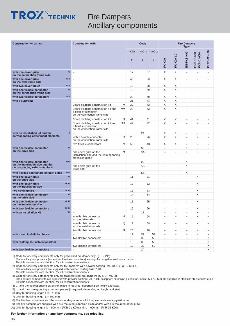
Fire DampersAncillary components
Construction or variant Combination with Code Fire DampersType
-K90 -K90-1 -K90-2
1) 2) 3)
with one cover grille 4) – 17 67 X X – – –on the connection frame sidewith one cover grille 4) 7) – 43 93 X X – – –on the wall frame sidewith two cover grilles 5) 7) – 18 68 X X – – –
with one flexible connector 4) – 19 69 X X – – –on the connection frame sidewith two flexible connectors 5) 7) – 20 70 X X – – –
with a subframe – 21 71 X X – – –
Board cladding construction kit 6) 22 72 X X – – –
Board cladding construction kit and 4) 6) 23 73 X X – – –a flexible connectoron the connection frame side
Board cladding construction kit 7) 41 91 X X – – –
Board cladding construction kit and 4) 7) 42 92 X X – – –a flexible connectoron the connection frame side
with an installation kit and the 7) – 24 X X – – –corresponding attachment elements with a flexible connector 4) 26 76 X X – – –
on the connection frame side
two flexible connectors 5) 58 A8 X X – – –
with one flexible connector 8) – S0 – – X – –on the drive side one cover grille on the 9) SA – – X – –
installation side and the correspondingextension piece
with one flexible connector 8) 9) – 0S – – X – –on the installation side and the one cover grille on the AS – – X – –corresponding extension piece drive side
with flexible connectors on both sides 8) 9) – SS – – X – –
with one cover grille 4) – 11 61 – – – X –on the drive sidewith one cover grille 4) 10) – 12 62 – – – X –on the installation sidetwo cover grilles 5) 10) – 13 63 – – – X –
with one flexible connector 4) – 14 64 – – – X –on the drive sidewith one flexible connector 4) 10) – 15 65 – – – X –on the installation sidewith two flexible connectors 5) 10) – 16 66 – – – X –
with an installation kit 10) – 17 – – – X –
one flexible connector 4) 18 68 – – – X –on the drive side
one flexible connector 4) 19 69 – – – X –on the installation side
two flexible connectors 5) 20 70 – – – X –
with round installation block – 12 32 52 – – – – Xtwo flexible connectors 18 38 58 – – – – X
with rectangular installation block – 13 33 53 – – – – Xtwo flexible connectors 19 39 59 – – – – X
with two flexible connectors – 24 – – – – X
1) Code for ancillary components only for galvanised fire dampers (e. g. …-K90).The ancillary components (exception: flexible connectors) are supplied in galvanised construction. Flexible connectors are identical for all construction variants.
2) Code for ancillary components only for fire dampers with powder coating RAL 7001 (e. g. …-K90-1).The ancillary components are supplied with powder coating RAL 7001. Flexible connectors are identical for all construction variants.
3) Code for ancillary components only for stainless steel fire dampers (e. g. …-K90-2).The ancillary components are supplied with powder coating RAL 7001, exception: extension pieces for Series EN-FKS-K90 are supplied in stainless steel construction.Flexible connectors are identical for all construction variants.
4) … and the corresponding extension piece (if required, depending on height and size).5) … and the corresponding extension pieces (if required, depending on height and size).6) Only for housing length L = 375 mm.7) Only for housing length L = 500 mm.8) The flexible connectors and the corresponding number of linking elements are supplied loose.9) The fire dampers are supplied with pre-mounted extension piece and/or with pre-mounted cover grille.
10) Only for housing lengths L = 500 mm (FKR-01-K90) and. L = 600 mm (FKR-02-K90).
For further information on ancillary components, see price list.
FK-K
90
FK-K
90-L
D
EN
-FK
S-K
90
FKR
-01-
K90
FKR
-02-
K90
FKR
S-0
2-K
90

37
Fire DampersAccessories
Construction Combination with Code Fire DampersType
with fusible link 72 °C or 95 °C 1) – Z00 X X X X X(Basic construction)
Limit switch indicates blade “CLOSED” Z01 X X X X X
Limit switch indicates blade “OPEN” Z02 X X X X X
Limit switch indicates blade “CLOSED” and “OPEN” Z03 X X X X X
with spring return actuator Series BLF 2) 3)
or BF and thermo-electricrelease mechanism BAE72A-S,manufactured by Belimo (power off to close)
Type BLF230-T TR 4) – Z42 – – – – X(with integrated limit switches)U = AC 230 V, 50…60 Hz, Protection Class IP 54 Z43 X X X – –
Type BF230-T TR – Z42 – – – X –(with integrated limit switches)U = AC 230 V, 50…60 Hz, Protection Class IP 54 Z43 X X – – –
Type BLF24-T-ST TR 4) – Z44 – – – – X(with integrated limit switches)U = AC 24 V, 50…60 Hz resp. DC 24 V, Z45 X X X – –Protection Class IP 54 AS-EM/B module, 5) ZA03 X X X – X
TROXNETCOM AS-Interface
LON-WA1/B2, 5) ZL06 X X X – XTROXNETCOM LON
LON-WA1/B2-AD, 5) ZL07 X X X – XTROXNETCOM LON
LON-WA1/B2-AD230, 5) ZL08 X X X – XTROXNETCOM LON
Type BF24-T-ST TR – Z44 – – – X –(with integrated limit switches)U = AC 24 V, 50…60 Hz resp. DC 24 V, Z45 X X – – –Protection Class IP 54
AS-EM/B module, 5) ZA03 X X – X –TROXNETCOM AS-Interface
LON-WA1/B2, 5) ZL06 X X – X –TROXNETCOM LON
LON-WA1/B2-AD, 5) ZL07 X X – X –TROXNETCOM LON
LON-WA1/B2-AD230, 5) ZL08 X X – X –TROXNETCOM LON
1) Fusible link 95 °C only licensed for Series FK-K90 · FK-K90-LD · EN-FKS-K90.
2) The ambient temperature for storage and operation must remain within the permissible ranges –20 °C to +50 °C(–30 °C to +50 °C for spring return actuator Type BLF).
3) Contacts in silver, gold-plated; Cable halogen-free.
4) Spring return actuator Type BLF for dimension combinations up to B x H = 797 x 400 mm (Series FK-K90 · FK-K90-LD).
5) TROXNETCOM elements mounted on the fire damper. Information on the TROXNETCOM communications solutions for the control of fire dampers on the basis ofLON and AS Interface can be found on the Internet site under Products/Automation and Systems Technology.
For further information on accessories, see price list.
FK-K
90
FK-K
90-L
D
EN
-FK
S-K
90
FKR
-01-
K90
FKR
-02-
K90
FKR
S-0
2-K
90

38
VARYCONTROL VAV Terminal BoxesType TVZ · TVA
TypeSupply air device TVZwith acoustic cladding TVZDExhaust air device TVAwith acoustic cladding TVAD
AccessoriesBasic construction 00Lip seal D1
Ancillary assembly1)
Explanations and additional chargesfor control components
Flow rate control1)
State flow rate rangeand units
Controlcomponentssee price list
Operating modee1)
M. MasterS. SlaveE. SingleF. Constant value
Size
1) If not otherwise specified in order, TVZ-Easy · TVA-Easy is delivered.
125160200250315400
Order Code TVZ 160 00 BC0 E0 200 - 900 m3/h/ / / / /
Dimensions (mm)
SizeTVZ · TVA TVZD · TVAD*
B H L B H L
125 300 236 1035 380 316 1075
160 410 236 1035 490 316 1075
200 560 281 1320 640 361 1360
250 700 311 1440 780 391 1480
315 900 361 1440 980 441 1480
400 1000 446 1820 1080 526 1860
Sound pressure level (dB[A])
∆pst = 100 Pa ∆pst = 200 Pa
Air-regenerated noise Case-radiated noise Air-regenerated noise Case-radiated noise
Size ØDa Flow V.
without with without with without with without withrate v=5m/s silencer silencer acoustic acoustic silencer silencer acoustic acoustic
range cladding cladding cladding claddingType TS Type TS
(mm) (m3/h) (m3/h) LpA LpA1 LpA2 LpA3 LpA LpA1 LpA2 LpA3
125 124 54 – 540 220 22 19 21 15 25 15 25 16
160 159 90 – 900 360 28 23 22 16 29 17 25 18
200 199 144 – 1458 580 20 17 24 18 22 13 28 20
250 249 216 – 2214 880 17 14 23 18 20 12 28 20
315 314 378 – 3690 1400 19 15 23 17 23 14 29 21
400 399 612 – 6048 2260 18 13 25 19 22 15 31 23
max
.120max. 600
ØD
a
70 70Ø 10,5
50
L
20
H
B
IEEEEOEEEEP
IEEEEEEOEEEEEEP
TEEEEEEEEEEZEEEEEEEEEU
TEEEEEZEEEEU
TEEEEEZEEEEU
TVZ
Maximum space required foractuator/control components
Nomenclature∆pst in Pa = Static pressure differentialv in m/s = Air velocity in circular spigotLpA in dB(A) = A-weighted sound pressure level of air-regenerated
noise, system attenuation taken into accountLpA1 in dB(A) = A-weighted sound pressure level of air-regenerated
noise with TX silencer, system attenuation takeninto account
LpA2 in dB(A) = A-weighted sound pressure level of case-radiatednoise, system attenuation taken into account
LpA3 in dB(A) = A-weighted sound pressure level of case-radiatednoise with additional acoustic cladding, systemattenuation taken into account
All sound pressure levels are based on 20 µPa.System attenuation: See documentation 5/1/EN/...
* with acoustic cladding
Ø 10.5

39
VARYCONTROL VAV ControllerType TVR
� D
a
max. 4801)
60050
max
. 200
max. 100
Maximum space required foractuator / control components
TypeVAV Controller TVRwith acoustic cladding TVRD
MaterialBasic construction steel, galv. 00Surface powder coated P1Colour RAL 7001
FlangeWITHOUT 00with flange both ends FL1)
AccessoriesNONE 00Matching flange both ends G2Lip seal both ends D2
Control components1)
Explanations and additional chargesfor control components
Flow rate control1)
State flow rate rangeand units
Operating modeM. MasterS. SlaveE. SingleF. Constant value
Size
1) not on TVRD with powder coating.
100125160200250315400
Order Code TVR - 00 - 00 160 00 BC0 E0 200 - 900 m3/h/ / / / /IEEEEOEEEEP
IEEEEOEEEEP
TEEEEEEEEEZEEEEEEEEU
TEEEEEZEEEEU
TEEEEEZEEEEU
IEEEEEEOEEEEEEP
IEEEEEEOEEEEEEP
TVR
Controlcompo-nentssee price list
Sound pressure level (dB[A])
∆pg = 100 Pa ∆pg = 200 Pa
Air-regenerated noise Case-radiated noise Air-regenerated noise Case-radiated noise
Size ØDa Flow V.
without with without with without with without withrate v=5m/s silencer silencer acoustic acoustic silencer silencer acoustic acoustic
range Series CS cladding cladding Series CS cladding cladding(L = 1000 mm) (L = 1000 mm)
(mm) (m3/h) (m3/h) LpA LpA1 LpA2 LpA3 LpA LpA1 LpA2 LpA3
100 99 36 – 349 140 42 24 25 22 47 29 26 19
125 124 54 – 551 220 43 21 25 19 48 33 27 19
160 159 90 – 900 360 46 27 27 21 51 37 30 21
200 199 144 – 1451 560 45 29 28 18 50 37 30 17
250 249 223 – 2221 880 44 28 28 19 49 37 35 19
315 314 371 – 3700 1400 45 33 35 22 50 39 40 22
400 399 605 – 6034 2260 44 33 36 22 49 37 40 23
Nomenclature∆pg in Pa = Total pressure differentialv in m/s = Air velocityLpA in dB(A) = A-weighted sound pressure level of air-regenerated
noise, system attenuation taken into accountLpA1 in dB(A) = A-weighted sound pressure level of air-regenerated
noise with CS silencer, system attenuation takeninto account
LpA2 in dB(A) = A-weighted sound pressure level of case-radiatednoise, system attenuation taken into account
LpA3 in dB(A) = A-weighted sound pressure level of case-radiatednoise with additional acoustic cladding, systemattenuation taken into account
All sound pressure levels are based on 20 µPa.System attenuation: See documentation 5/3/EN/...
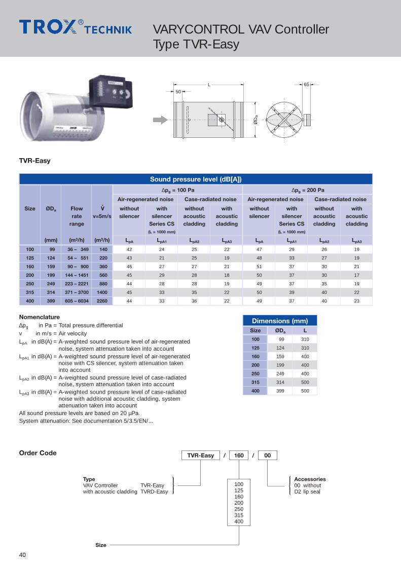
40
VARYCONTROL VAV ControllerType TVR-Easy
IEEEEOEEEEP
TEEEEEZEEEEU
ØD
a
L
50
65
TVR-Easy / / 00160
100125160200250315400
TypeVAV Controller TVR-Easywith acoustic cladding TVRD-Easy
Size
Accessories00 withoutD2 lip seal
Order Code
Dimensions (mm)Size ØDa L
100 99 310
125 124 310
160 159 400
200 199 400
250 249 400
315 314 500
400 399 500
Nomenclature∆pg in Pa = Total pressure differentialv in m/s = Air velocityLpA in dB(A) = A-weighted sound pressure level of air-regenerated
noise, system attenuation taken into accountLpA1 in dB(A) = A-weighted sound pressure level of air-regenerated
noise with CS silencer, system attenuation takeninto account
LpA2 in dB(A) = A-weighted sound pressure level of case-radiatednoise, system attenuation taken into account
LpA3 in dB(A) = A-weighted sound pressure level of case-radiatednoise with additional acoustic cladding, systemattenuation taken into account
All sound pressure levels are based on 20 µPa.System attenuation: See documentation 5/3.5/EN/...
Sound pressure level (dB[A])
∆pg = 100 Pa ∆pg = 200 Pa
Air-regenerated noise Case-radiated noise Air-regenerated noise Case-radiated noise
Size ØDa Flow V.
without with without with without with without withrate v=5m/s silencer silencer acoustic acoustic silencer silencer acoustic acoustic
range Series CS cladding cladding Series CS cladding cladding(L = 1000 mm) (L = 1000 mm)
(mm) (m3/h) (m3/h) LpA LpA1 LpA2 LpA3 LpA LpA1 LpA2 LpA3
100 99 36 – 349 140 42 24 25 22 47 29 26 19
125 124 54 – 551 220 43 21 25 19 48 33 27 19
160 159 90 – 900 360 46 27 27 21 51 37 30 21
200 199 144 – 1451 560 45 29 28 18 50 37 30 17
250 249 223 – 2221 880 44 28 28 19 49 37 35 19
315 314 371 – 3700 1400 45 33 35 22 50 39 40 22
400 399 605 – 6034 2260 44 33 36 22 49 37 40 23
TVR-Easy

41
VARYCONTROL VAV ControllerType TVJ-Easy · TVT-Easy
400 B38
38
H
TVJ-Easy / 600 x 400
B x HTypeVAV Controller TVJ-Easywith acoustic cladding TVJD-EasyVAV Controller, airtight TVT-Easywith acoustic cladding TVTD-Easy
Order Code
Sound pressure level (dB[A])∆pg = 100 Pa ∆pg = 200 Pa
Air-regenerated noise Case-radiated noise Air-regenerated noise Case-radiated noise
B x H Flow V.
without with without with without with without withrate v=5m/s silencer silencer acoustic acoustic silencer silencer acoustic acoustic
range cladding cladding cladding claddingTX TX
(m3/h) (m3/h) LpA LpA1 LpA2 LpA3 LpA LpA1 LpA2 LpA3
200 100 162– 774 360 40 24 32 24 46 27 36 28300 234– 1152 540 41 25 33 25 47 28 37 29400 306– 1530 720 42 26 34 26 48 29 38 30500 378– 1926 900 43 27 35 27 49 30 39 31600 468– 2340 1080 44 28 36 28 50 31 40 32200 200 306– 1494 720 39 23 35 27 46 27 39 31300 450– 2232 1080 40 24 36 28 47 28 40 32400 594– 2070 1440 41 25 37 29 48 29 41 33500 738– 3726 1800 42 26 38 30 49 30 42 34600 900– 4500 2160 43 27 39 31 50 31 43 35700 1044– 5220 2520 44 28 40 32 51 32 44 36800 1188– 5940 2880 44 28 40 32 51 32 44 36300 300 666– 3312 1620 40 24 37 30 46 28 42 34400 882– 4428 2160 41 25 38 31 47 29 43 35500 1098– 5526 2700 42 26 39 32 48 30 44 36600 1332– 6660 3240 43 27 40 33 49 31 45 37700 1548– 7740 3780 44 28 41 34 50 32 46 38800 1764– 8820 4320 44 28 41 34 50 32 46 38900 1998– 9972 4860 45 29 42 35 51 33 47 39
1000 2234–11160 5400 45 29 42 35 51 33 47 39400 400 1170– 5868 2880 41 25 39 32 47 29 44 36500 1476– 7344 3600 42 26 40 33 48 30 45 37600 1764– 8820 4320 43 27 41 34 49 31 46 38700 2052–10260 5040 44 28 42 35 50 32 47 39800 2340–11700 5760 44 28 42 35 50 32 47 39900 2646–13212 6480 45 29 43 36 51 33 48 40
1000 2952–14760 7200 45 29 43 36 51 33 48 40500 500 1836– 9144 4500 41 26 41 34 48 30 46 38600 2196–10980 5400 42 27 42 35 49 31 47 39700 2556–12780 6300 43 28 43 36 50 32 48 40800 2916–14580 7200 43 28 43 36 50 32 48 40900 3294–16952 8100 44 29 44 37 51 33 49 41
1000 3672–18360 9000 44 29 44 37 51 33 49 41600 600 2628–13140 6480 42 27 43 36 49 31 48 40800 3492–17460 8640 43 28 44 37 50 32 49 41
1000 4392–21960 10800 44 29 45 38 51 33 50 42800 800 4680–23400 11520 41 25 46 39 47 30 51 43
1000 5832–29160 14400 42 26 47 40 48 31 52 441000 1000 7272–36360 18000 42 26 48 41 48 31 53 45
IEEEEEEEEEOEEEEEEEEEP
TVJ · TVT-Easy
Nomenclature∆pg in Pa = Total pressure differentialv in m/s = Air velocityLpA in dB(A) = A-weighted sound pressure level of air-regenerated noise, system attenuation
taken into accountLpA1 in dB(A) = A-weighted sound pressure level of air-regenerated noise with TX silencer,
system attenuation taken into accountLpA2 in dB(A) = A-weighted sound pressure level of case-radiated noise, system attenuation
taken into accountLpA3 in dB(A) = A-weighted sound pressure level of case-radiated noise with additional
acoustic cladding, system attenuation taken into accountAll sound pressure levels are based on 20 µPa.System attenuation: See documentation 5/4.1/EN/...
approx. 70
appr
ox. 7
0
Longitudinal hole 20 x 13

42
VARYCONTROLType VAV-EasySet
VAV-EasySet
Nominal flow ratesV..
NomD(m3/h)
100 350
125 550
140 702
160 900
200 1450
224 1890
250 2220
315 3700
400 6035
TROX VAV-EasySet is an assembly consisting of control unitcomponents to refurbish VAV terminal units. VAV-EasySet issuitable for systems with a round duct system.
� Differential pressure sensor to measure the flow rate
� TROX Compact Controller as housing unit for air terminalunits and actuator
� Adjustment of the flow rate ‡min and ‡max on scaledpotentiometers, without a special adjuster
� Function check with green indicator lamp
VAV-EasySet
Type
Order Code
> 2 D> 0,5 D
+–
36
60 45° 45°
> 1,5 D > 2 D
Differential pressure device Differential pressure sensor
Duct sytemD = 100 ... 250
Flow rate direction
Air lineD = 280 ... 400
Measuring point
Maximum hose length of 3 mper measuring line
> 1.5 D> 0.5 D
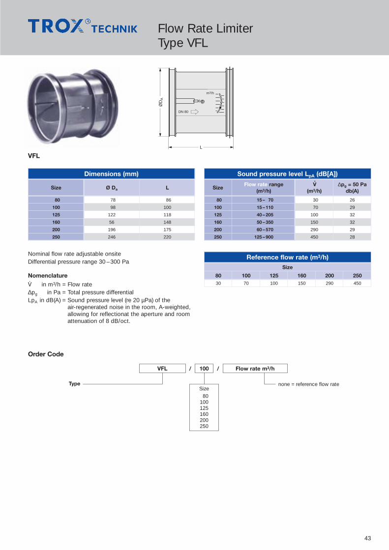
43
Flow Rate LimiterType VFL
VFLØ
DA
L
DN 80
m3/h
Dimensions (mm)
Size Ø Da L
80 78 86
100 98 100
125 122 118
160 56 148
200 196 175
250 246 220
Reference flow rate (m3/h)Size
80 100 125 160 200 25030 70 100 150 290 450
Sound pressure level LpA (dB[A])
SizeFlow rate range V
.∆pg = 50 Pa
(m3/h) (m3/h) db(A)
80 15 – 70 30 26
100 15 – 110 70 29
125 40 – 205 100 32
160 50 – 350 150 32
200 60 – 570 290 29
250 125 – 900 450 28
Nominal flow rate adjustable onsiteDifferential pressure range 30 – 300 Pa
Nomenclature
‡ in m3/h = Flow rate∆pg in Pa = Total pressure differentialLpA in dB(A) = Sound pressure level (re 20 µPa) of the
air-regenerated noise in the room, A-weighted,allowing for reflectionat the aperture and roomattenuation of 8 dB/oct.
TypeSize
80100125160200250
none = reference flow rate
Order Code
VFL 100 Flow rate m3/h/ /
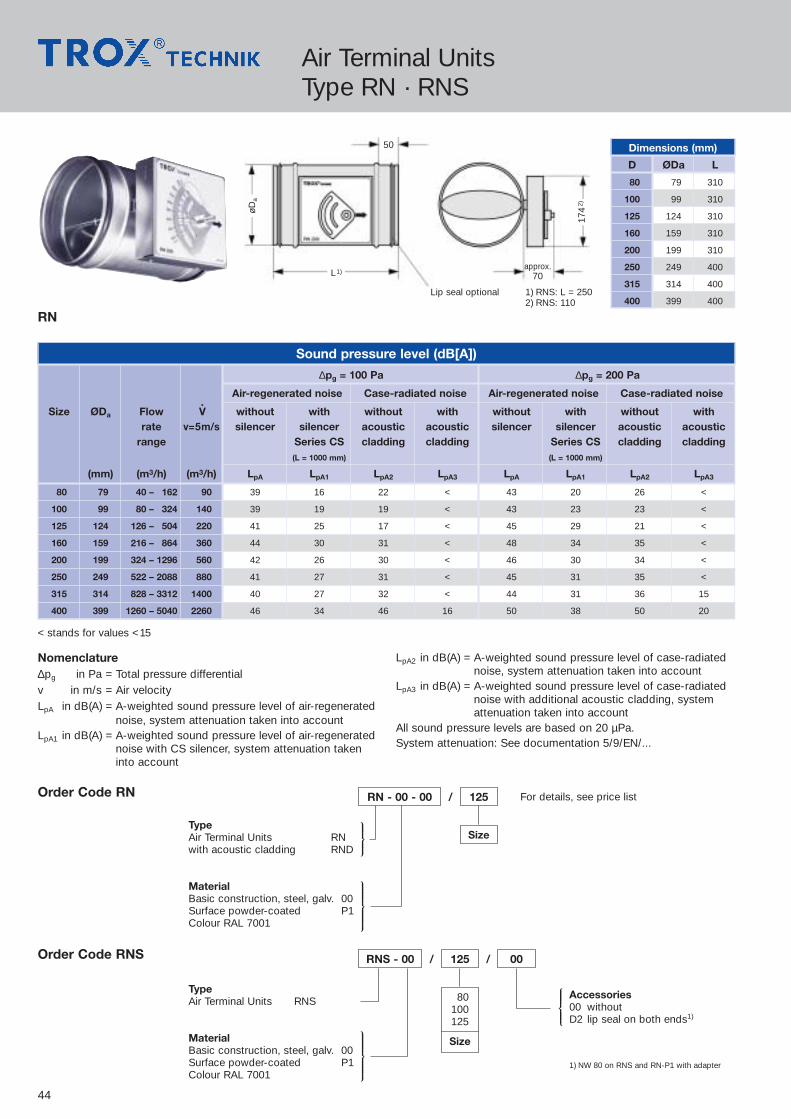
44
1) NW 80 on RNS and RN-P1 with adapter
Air Terminal UnitsType RN · RNS
IEEEEOEEEEP
IEEEEEEEOEEEEEEEP
Dimensions (mm)
D ØDa L
80 79 310
100 99 310
125 124 310
160 159 310
200 199 310
250 249 400
315 314 400
400 399 400
øDa
50
174
2)
approx.70
Lip seal optional 1) RNS: L = 2502) RNS: 110
L1)
< stands for values <15
RN - 00 - 00 / 125
SizeTypeAir Terminal Units RNwith acoustic cladding RND
MaterialBasic construction, steel, galv. 00Surface powder-coated P1Colour RAL 7001
Order Code RN For details, see price list
IEEEEEEEOEEEEEEEP
RNS - 00 / /125 00
80100125
Size
TypeAir Terminal Units RNS
MaterialBasic construction, steel, galv. 00Surface powder-coated P1Colour RAL 7001
Order Code RNS
Sound pressure level (dB[A])
∆pg = 100 Pa ∆pg = 200 Pa
Air-regenerated noise Case-radiated noise Air-regenerated noise Case-radiated noise
Size ØDa Flow V.
without with without with without with without withrate v=5m/s silencer silencer acoustic acoustic silencer silencer acoustic acoustic
range Series CS cladding cladding Series CS cladding cladding(L = 1000 mm) (L = 1000 mm)
(mm) (m3/h) (m3/h) LpA LpA1 LpA2 LpA3 LpA LpA1 LpA2 LpA3
80 79 40 – 162 90 39 16 22 < 43 20 26 <
100 99 80 – 324 140 39 19 19 < 43 23 23 <
125 124 126 – 504 220 41 25 17 < 45 29 21 <
160 159 216 – 864 360 44 30 31 < 48 34 35 <
200 199 324 – 1296 560 42 26 30 < 46 30 34 <
250 249 522 – 2088 880 41 27 31 < 45 31 35 <
315 314 828 – 3312 1400 40 27 32 < 44 31 36 15
400 399 1260 – 5040 2260 46 34 46 16 50 38 50 20
RN
TEEEEEZEEEEU
Accessories00 withoutD2 lip seal on both ends1)
Nomenclature∆pg in Pa = Total pressure differentialv in m/s = Air velocityLpA in dB(A) = A-weighted sound pressure level of air-regenerated
noise, system attenuation taken into accountLpA1 in dB(A) = A-weighted sound pressure level of air-regenerated
noise with CS silencer, system attenuation takeninto account
LpA2 in dB(A) = A-weighted sound pressure level of case-radiatednoise, system attenuation taken into account
LpA3 in dB(A) = A-weighted sound pressure level of case-radiatednoise with additional acoustic cladding, systemattenuation taken into account
All sound pressure levels are based on 20 µPa.System attenuation: See documentation 5/9/EN/...

45
Air Terminal UnitsType EN
approx. 35
38
38
B 400
H
Longitudinalhole 20 x 13
EN / / /400 x 200 B50 ‡min - ‡max
B x HTypeAir Terminal Units ENwith acoustic cladding END
ActuatorsSee price list
Order Code
Sound pressure level (dB[A])
∆pg = 100 Pa ∆pg = 200 Pa
Air-regenerated noise Case-radiated noise Air-regenerated noise Case-radiated noise
B x H Flow V.
without with without with without with without withrate v=5m/s silencer silencer acoustic acoustic silencer silencer acoustic acoustic
range cladding cladding cladding claddingSerie TX Serie TX
(m3/h) (m3/h) LpA LpA1 LpA2 LpA3 LpA LpA1 LpA2 LpA3
200 100 144– 576 360 40 30 32 27 48 35 38 32
300 234– 936 540 42 31 34 29 49 36 41 34
300 150 378– 1512 810 42 29 34 27 49 35 40 32
300 200 460– 1872 1080 43 27 34 25 52 35 42 33
400 756– 3024 1440 40 24 33 25 49 33 41 32
500 828– 3312 1800 38 23 31 23 47 31 39 31
600 918– 3672 2160 36 23 31 24 44 31 39 32
400 250 792– 3168 1800 41 26 34 25 51 34 42 33
500 1080– 4320 2250 39 23 32 23 48 32 40 31
600 1152– 4608 2700 38 24 32 24 47 32 40 33
400 300 1134– 4536 2160 44 27 37 27 52 35 44 35
500 1350– 5400 2700 41 25 35 26 49 33 42 33
600 1512– 6048 3240 39 24 32 24 47 31 40 31
400 400 1512– 6048 2880 46 29 39 30 54 37 47 37
500 1656– 6624 3600 43 26 37 27 52 34 45 35
600 1836– 7344 4320 41 26 36 27 49 34 44 34
500 500 2160– 8640 4500 46 28 40 30 54 36 48 38
600 2034– 9216 5400 43 28 39 29 51 36 47 37
600 600 3024–12096 6480 45 28 41 31 53 36 48 38
IEEEEOEEEEP
EN
Nomenclature∆pg in Pa = Total pressure differentialv in m/s = Air velocityLpA in dB(A) = A-weighted sound pressure level of air-regenerated
noise, system attenuation taken into accountLpA1 in dB(A) = A-weighted sound pressure level of air-regenerated
noise with TX silencer, system attenuation takeninto account
LpA2 in dB(A) = A-weighted sound pressure level of case-radiatednoise, system attenuation taken into account
LpA3 in dB(A) = A-weighted sound pressure level of case-radiatednoise with additional acoustic cladding, systemattenuation taken into account
All sound pressure levels are based on 20 µPa.System attenuation: See documentation 5/9.1/EN/...

46
Circular AttenuatorsType C
Construction with plug type spigots (Standard)
CA100; Insulation thickness = 100 mm
Insertion loss (dB) for L = 500 mm
NWfm, oct. (Hz)
63 125 250 500 1k 2k 4k 8k
100 4 9 12 18 35 33 26 14
125 4 7 10 17 31 26 19 11
160 3 6 9 15 28 20 13 8
200 3 5 8 15 25 16 9 7
250 2 4 7 14 21 13 6 5
315 2 3 6 13 18 10 4 4
400 1 3 6 12 17 8 3 3
CF050.../CS050; Insulation thickness = 50 mm
Insertion loss (dB) for L = 500 mm
NWfm, oct. (Hz)
63 125 250 500 1k 2k 4k 8k
80 4 5 11 20 30 27 16 12
100 3 4 9 17 24 21 12 10
125 2 3 7 14 20 16 11 9
160 2 2 6 12 17 14 8 6
200 1 2 5 12 16 11 6 5
250 1 2 4 12 15 8 5 4
315 1 1 3 9 12 6 4 3
400 1 1 3 7 9 6 4 3
Insertion loss (dB) for L = 1500 mm
NWfm, oct. (Hz)
63 125 250 500 1k 2k 4k 8k
80 11 14 33 48 50 50 47 37
100 10 11 27 44 50 50 37 30
125 7 9 21 41 50 46 33 27
160 5 7 17 37 48 42 24 19
200 4 6 14 37 48 34 18 15
250 3 5 11 35 45 25 14 11
315 2 4 10 26 35 19 12 10
400 2 4 9 20 26 17 11 8
Insertion loss (dB) for L = 1500 mm
NWfm, oct. (Hz)
63 125 250 500 1k 2k 4k 8k
250 4 11 21 37 41 27 15 12
315 3 9 18 34 35 21 10 9
400 3 7 16 32 31 16 7 7
450 2 6 15 31 29 14 6 6
500 2 6 14 30 27 13 5 6
560 2 5 13 29 25 11 4 5
630 2 5 12 28 23 10 4 4
710 2 5 11 27 22 9 3 4
800 2 4 11 26 20 8 2 3
75
�d
a�
D
L75
Dimensions (mm)Flow Insulation thicknessrate 25 mm 50 mm
surface Øda Øda ØD ØDNW (m2) (mm) (mm) (mm) (mm)
80 0.005 79 80 135 191100 0.008 99 100 160 211125 0.012 124 125 191 235160 0.020 159 160 221 271200 0.031 199 200 261 311250 0.050 249 250 311 366315 0.079 314 315 376 476400 0.126 399 400 461 511
Type
Insulation thickness in mm1)
Size
Length in mm
not required
Connection variations
000 = Plug type spigotsVD2 = Lip seal on both ends
Order Code CA100 160 x 1000 00 VD2/ / /
1) Insulation thickness 25 and 50 mm available. (If the insulation thickness is not specified on the order, thickness 50 mm is delivered as standard.)
CA CF
Nomenclaturefm, oct. in Hz = centre octave frequencyNW = SizeL = Length

47
Circular AttenuatorsType C
Insulation thickness 50 mm: � D = � d + 100 mmInsulation thickness 100 mm: � D = � d + 200 mm1) Low-leakage performance to DIN V 24194 Part 2, Class II without
additional on-site seals. Available up to and including size 400
Insulation thickness in mm 2)
Type 1)
Example:
Size
Length in mmMatching flange(s)00 = noneGZ = both ends
Connection variations000 = Plug-type spigotsVF2 = Flange on both ends3)
VD2 = Lip seal both ends4)
Order Code
CB 100 315 x 1000 GZ VF2/ / /
1) On Type CB: Coned end = air inlet end2) Insulation thickness 50 mm possible up to size 400 (if no insulation thickness is specified on order, thickness 100 mm is delivered as standard)3) Flange on both ends: L-20 mm4) Lip seal on both ends available for size 100...400
TEEEEEEEZEEEEEEEU
TEEEEEZEEEEEU
Construction with plug type spigots (Standard)
�d
�D
L
Dimensions (mm)Free Plain flange in accarea with DIN 24154 Part 1
Ød Øk b x s no. ofNW (m2) (mm) (mm) (mm) holes
100 0.008 99 132 25 x 3 4125 0.012 124 157 25 x 3 4160 0.020 159 192 25 x 4 6200 0.031 199 233 25 x 4 6250 0.050 249 283 25 x 4 6315 0.079 314 352 30 x 4 8400 0.126 399 438 30 x 4 8450 0.158 448 488 30 x 4 8500 0.198 498 538 30 x 4 8560 0.251 558 600 35 x 4 12630 0.316 628 670 35 x 4 12710 0.397 708 750 35 x 4 12800 0.499 798 840 35 x 4 16900 0.628 898 940 35 x 4 16
1000 0.785 998 1041 35 x 4 16
CB100; Insulation thickness = 100 mm
Insertion loss (dB) for L = 1000 mm
NWfm, oct. (Hz)
63 125 250 500 1k 2k 4k 8k
250 5 10 17 30 47 50 50 36
315 4 9 15 27 44 45 39 27
400 3 7 13 25 40 38 29 21
450 3 7 12 24 39 35 26 18
500 2 6 12 23 38 33 24 17
560 2 6 11 22 36 31 21 15
630 2 5 11 21 34 29 19 13
710 2 5 10 20 33 27 17 12
800 2 5 9 19 31 25 14 10
900 2 4 9 18 30 23 13 9
1000 2 4 8 17 29 22 12 8
Insertion loss (dB) for L = 1500 mm
NWfm, oct. (Hz)
63 125 250 500 1k 2k 4k 8k
250 7 14 22 41 50 50 50 44
315 7 12 20 37 50 50 50 34
400 6 10 17 33 50 50 40 26
450 5 9 16 31 50 50 36 23
500 5 9 16 30 50 50 33 21
560 4 8 15 30 50 48 29 19
630 4 8 14 29 50 44 26 16
710 4 7 13 28 50 41 23 14
800 3 6 13 26 49 37 20 12
900 3 6 12 24 47 34 17 11
1000 3 6 11 23 45 33 16 10
Selection table
NW Flow rate V. Airflow Airway- ∆pt LWAvelocity speed
l/s m3/h m/s m/s Pa dB(A)
250 287 1035 6 9.9 41 44
315 459 1651 6 9.9 37 45
400 743 2674 6 9.9 33 45
450 942 3390 6 9.9 32 46
500 1164 4190 6 9.9 31 46
560 1462 5263 6 9.9 30 46
630 1853 6669 6 9.9 29 47
710 2355 8480 6 9.9 28 47
800 2993 10776 6 9.9 27 47
900 3792 13650 6 9.9 27 48
1000 4684 16863 6 9.9 26 48
CB CB
Nomenclaturefm, oct. in Hz = centre octave frequencyNW = SizeL = Length
∆pt in Pa = Total pressure loss for L = 1000 mm

48
Splitter AttenuatorType MSA 200
Insertion loss (dB) for airway width s = 100 mm
L (mm)fm (Hz)
63 125 250 500 1000 2000 4000 8000
500 2 4 12 12 15 11 9 8
1000 4 10 22 23 26 19 13 11
1500 5 14 31 33 36 25 16 13
2000 6 19 41 43 46 30 18 16
2500 8 24 49 50 50 37 22 18
3000 10 30 50 50 50 43 26 19
Combination (Width/Height) at ∆pt approx. 50 Pa; Air-regenerated noise max. 46 dB(A) per m2 at L = 1500 mm
n = number of splitters
B
H
L
60000
‡ (m
3 /h)
50000
40000
30000
20000
10000
0
300 400 500 600 700 800 900 1000H (mm)
B = 2400, n 8
B = 2100, n 7
B = 1800, n 6
B = 1500, n 5
B = 1200, n 4
B = 900, n 3
B = 600, n 2
B = 300, n 1
1100 1200 1300 1400 1500 1600 1700 1800
Type
Splitter thickness in mm
Airway width s in mm
No. of adjacent splitters n; in attenutatorin B dimension
F = glass fibre matting1)
L = glass fibre matting under perforated plate
Length L in mm
Height H in mm
Width B in mm
P = air duct section 30 mm1)
W = Angular frame 35 x 3 mm2)
Splitter surface
Max. four points each
Connection frame
Order Code Splitter Attenuator
MSA200 - 100 - 3 - PF 900 x 600 x 1500/
1) Standard hygienic design2) Partitioned attenuators obligatory for division of the B and/or H dimension
IEEOEEP
IEEOEEP
IEEOEEP
IEEOEEP
IEEOEEP
IEEEEEOEEEEEP
MSA 200 MSA 200
Nomenclaturefm in Hz = octave centre frequency∆pt in Pa = total pressure drop‡ in m3/h = flow rate

B U S IN E S S P A R T N E R O F
R
www.bradflo.com
Tollfree 1300 138 688
Head Office - Albury20 Garland AvenueNorth Albury NSW 2640Telephone: (02) 6058 6900Facsimile: (02) 6058 6928Email: [email protected]
Brisbane5/29-41 Lysaght StreetAcacia Ridge QLD 4110Telephone: (07) 3216 9611Facsimile: (07) 3216 9477Email: [email protected]
Cairns351 Spence Street Bungalow Cairns QLD 4870Telephone: (07) 4035 2477Facsimile: (07) 4035 2280Email: [email protected]
Canberra3.1 Dairy Road Fyshwick ACT 2609Telephone: (02) 6239 3400Facsimile: (02) 6239 3404Email: [email protected]
Melbourne7 Rushdale StreetKnoxfield VIC 3180Telephone: (03) 9764 9656Facsimile: (03) 9764 9661Email: [email protected]
Riverina920 Metry StreetAlbury NSW 2640Telephone: (02) 6040 6034Facsimile: (02) 6040 6035Email: [email protected]
Sydney5-7 Salisbury StreetSilverwater NSW 2128Telephone: (02) 9735 7000Facsimile: (02) 9735 7011Email: [email protected]
Townsville5 Greg Jabs Court Garbutt Townsville QLD 4814Telephone: (07) 4725 7500Facsimile: (07) 4725 5577Email: [email protected]
Trox Australia Pty LtdUnit 8, 21 Huntingdale RoadBurwood VIC 3125Telephone: (03) 9888 0033Facsimile: (03) 9808 3956Email: [email protected]


