Programmer’s Reference Guide – Document #50-70307-001 Rev. F Copyright TROY Group Inc., 2001 – 2006 Preface-2
Notice TROY GROUP, INC. MAKES NO WARRANTY OF ANY KIND WITH REGARD TO THIS MATERIAL, INCLUDING BUT NOT LIMITED TO, THE IMPLIED WARRANTIES OF MERCHANTABILITY AND FITNESS FOR A PARTICULAR PURPOSE.
TROY Group Inc. shall not be liable for errors contained herein or for incidental or consequential damages in connection with the furnishing, performance, or use of this material.
This document contains proprietary information that is protected by copyright. All rights are reserved. No part of this document may be photocopied, reproduced, or translated into another language without the prior written consent of TROY Group, Inc. The information contained in this document is subject to change without notice.
Preface
Programmer’s Reference Guide – Document #50-70307-001 Rev. F Copyright TROY Group Inc., 2001 – 2006 Preface-3
Printing History This manual was created using Microsoft WORD 2000 on a Hewlett Packard personal computer. The body text is printed in Times New Roman fonts.
First Edition – January 2001 Second Edition – July 2001 Third Edition – October 2001 Forth Edition – January 2002 Fifth Edition – December 2002 Sixth Edition – May 2004 Seventh Edition – April 2006
NOTICE This document is the current edition of the TROY Security Printing Solutions Programmer’s Reference Guide, containing extensions to the PCL 5e printer language for the exclusive use of TROY Group Inc. and its assignees.
Preface
Programmer’s Reference Guide – Document #50-70307-001 Rev. F Copyright TROY Group Inc., 2001 – 2006 Preface-4
Trademark Credits TROY, TROY MICR, TROY MICR Secure, TROY MICR Secure EX, TROYmark and TROY ExPT are U.S. registered trademarks of TROY Group Inc. (NASDAQ: TROY). LaserJet, HP and PCL are registered trademarks of the Hewlett Packard Company. Any other trademarks used within this document are the property of their rightful owners, whether explicitly noted or otherwise.
This product includes cryptographic software written by Eric Young ([email protected]). This product includes software written by Tim Hudson ([email protected]). ERIC YOUNG COPYRIGHT AND LICENSE INFORMATION
1. Redistributions of source code must retain the copyright notice, this list of conditions and the following disclaimer.
2. Redistributions in binary form must reproduce the above copyright notice, this list of conditions and the following disclaimer in the documentation and/or other materials provided with the distribution.
3. All advertising materials mentioning features or use of this software must display the following acknowledgement: "This product includes cryptographic software written by Eric Young ([email protected])" The word `cryptographic' can be left out if the routines from the library being used are not cryptographic related :-).
4. If you include any Windows specific code (or a derivative thereof) from the apps directory (application code) you must include an acknowledgement: "This product includes software written by Tim Hudson ([email protected])".
THIS SOFTWARE IS PROVIDED BY ERIC YOUNG ``AS IS'' AND ANY EXPRESS OR IMPLIED WARRANTIES, INCLUDING, BUT NOT LIMITED TO, THE IMPLIED WARRANTIES OF MERCHANTABILITY AND FITNESS FOR A PARTICULAR PURPOSE ARE DISCLAIMED. IN NO EVENT SHALL THE AUTHOR OR CONTRIBUTORS BE LIABLE FOR ANY DIRECT, INDIRECT, INCIDENTAL, SPECIAL, EXEMPLARY, OR CONSEQUENTIAL DAMAGES (INCLUDING, BUT NOT LIMITED TO, PROCUREMENT OF SUBSTITUTE GOODS OR SERVICES; LOSS OF USE, DATA, OR PROFITS; OR BUSINESS INTERRUPTION) HOWEVER CAUSED AND ON ANY THEORY OF LIABILITY, WHETHER IN CONTRACT, STRICT LIABILITY, OR TORT (INCLUDING NEGLIGENCE OR OTHERWISE) ARISING IN ANY WAY OUT OF THE USE OF THIS SOFTWARE, EVEN IF ADVISED OF THE POSSIBILITY OF SUCH DAMAGE.
The license and distribution terms for any publicly available version or derivative of this code cannot be changed, i.e., this code cannot simply be copied and put under another distribution license [including the GNU Public License.]
Preface
Programmer’s Reference Guide – Document #50-70307-001 Rev. F Copyright TROY Group Inc., 2001 – 2006 Preface-5
Inside This Guide TROY Group Inc. has developed a set of programming extensions to the Hewlett Packard PCL 5e programming language. These extensions are available in the TROY MICR Series printers, sold exclusively by TROY Group Inc. and its distributors. While some of the features contained in this guide are compatible with previous printers sold by TROY, this guide was specifically developed to support the TROY 4200, 4300, and 9000 Series (or later) printers.
This guide provides a technical definition of these extension commands and how to apply them within the context of a program to perform useful work. As such, this guide was written for people with some programming knowledge, and more specifically, programming knowledge using the HP PCL 5e printer language. Before attempting to use this guide, it is strongly recommended the reader review the PCL 5 Printer Language Technical Reference Guide and the Printer Job Language Technical Reference Manual, available from Hewlett Packard Company in the PCL 5e Technical Reference Bundle.
Because virtually all TROY PCL 5e extension commands require the programmer to be able to write an escape character (decimal 27, hexadecimal Øx1B) into a file or out to the printer, before beginning to use this guide, be certain to identify within your programming environment how you will output this character. Many, if not all, Microsoft Windows printer drivers do not support sending the escape character directly to a printer. Should you need assistance, please contact TROY Technical Support.
Technical assistance is available Monday – Friday, 8:00 AM to 8:00 PM (Eastern Standard Time). Please call (800) 332-6427 or (304) 232-0899 (outside the U.S.).
You may also send a fax to TROY Technical Support at (304) 232-0996 or an email to: [email protected]
This guide has been written as a companion to the TROY Security Printing Solutions User’s Guide. You are encouraged to review the TROY Quick-Start Guide, the TROY Security Printing Solutions User’s Guide, and the TROY MICR Basics Handbook. It is recommended that you have these documents available before proceeding.
Preface
Programmer’s Reference Guide – Document #50-70307-001 Rev. F Copyright TROY Group Inc., 2001 – 2006 Preface-6
Chapter Summaries
Chapter 1 – Introduction This chapter provides a brief introduction to this guide, defining how the guide is organized and how to effectively use the information presented.
Chapter 2 – Security Settings This chapter introduces the administrator and user-level security for the printer. Configuring the printer requires an administrator password (login) and placing the printer in a special download mode. Many of the print job-based secure features of TROY Security Printing Solutions also require the use of a user login. This chapter defines how to programmatically define and use login security in the printer.
Chapter 3 – Printing Control This chapter describes many of the printer-centric features of TROY Security Printing Solutions and how to control them programmatically. Refer to this chapter for the following commands: MICR mode, printer type, TROY ExPT offsets, automatic image rotation, paper tray mapping, configuration and quality page printing, alternate escape character definition, alternate command set, Printer, MICR and JOB PIN security, languages supported and related commands.
Chapter 4 – Secure and Public Resources This chapter describes how printer resources (fonts, macros, and data files) can be stored in the TROY flash-file system contained on the TROY DIMM/memory card. Commands to add and delete fonts, macros, and data files as either public or secure resources, and how to print the list of current resources in the printer are discussed.
Chapter 5 – Data Capture Fonts This chapter describes how to create your own data capture fonts for TROY Security Printing Solutions. Data capture fonts are used in the TROYmark™ security printing and audit reporting. Also covered is the invisible font feature. NOTE: The TROY Printer Utility can also be used to easily create data capture fonts.
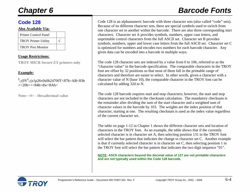
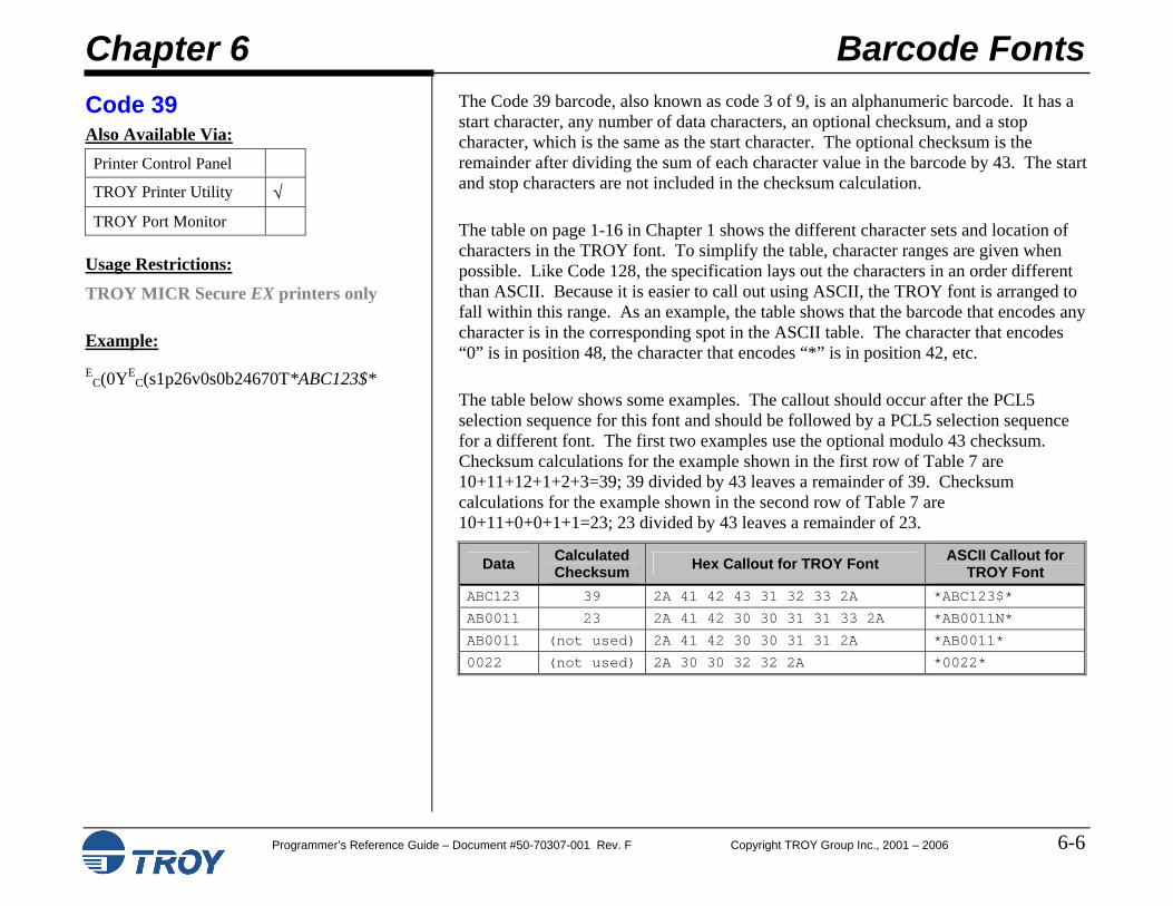
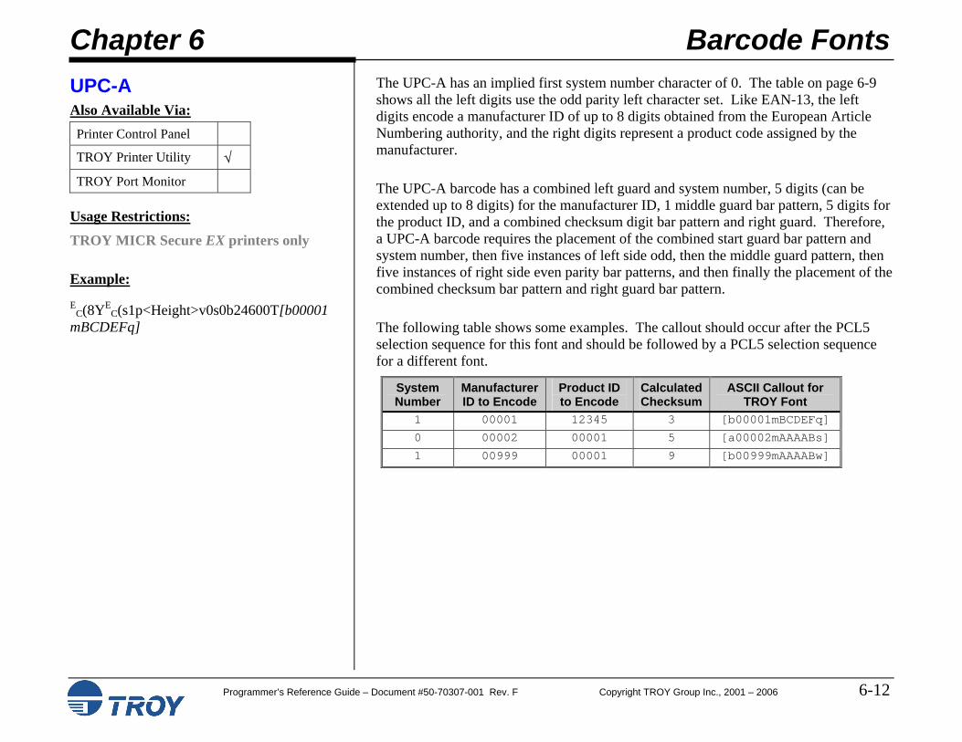
Chapter 6 – Barcode Fonts This chapter describes how to create and print nine different types of correctly formatted and scanable linear barcodes using a PCL5 selection sequence.
Preface
Programmer’s Reference Guide – Document #50-70307-001 Rev. F Copyright TROY Group Inc., 2001 – 2006 Preface-7
Chapter Summaries (cont.)
Chapter 7 – TROYmark™ Settings This chapter describes how to enable and specify the inclusion and exclusion regions for TROYmark™ security printing. TROYmark™ pattern level selection is discussed, as well as custom pattern creation.
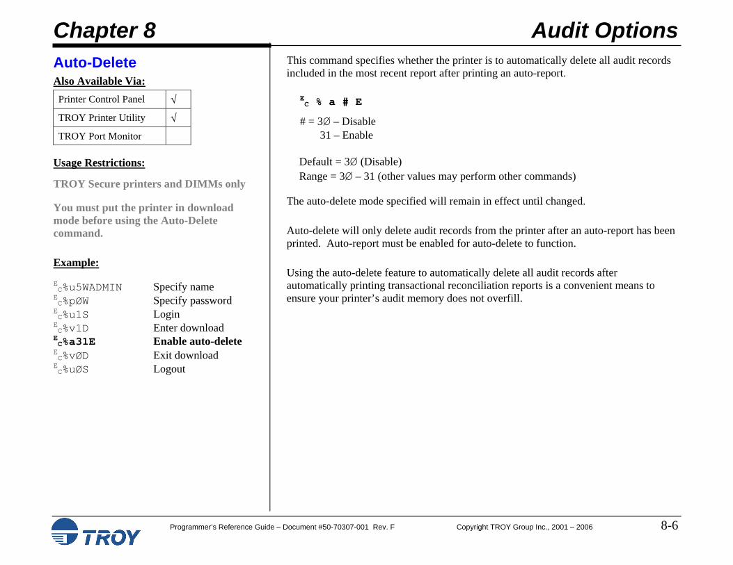
Chapter 8 – Audit Options This chapter introduces all the audit settings that can be used to control how audit records are stored and how custom audit reports can be created.
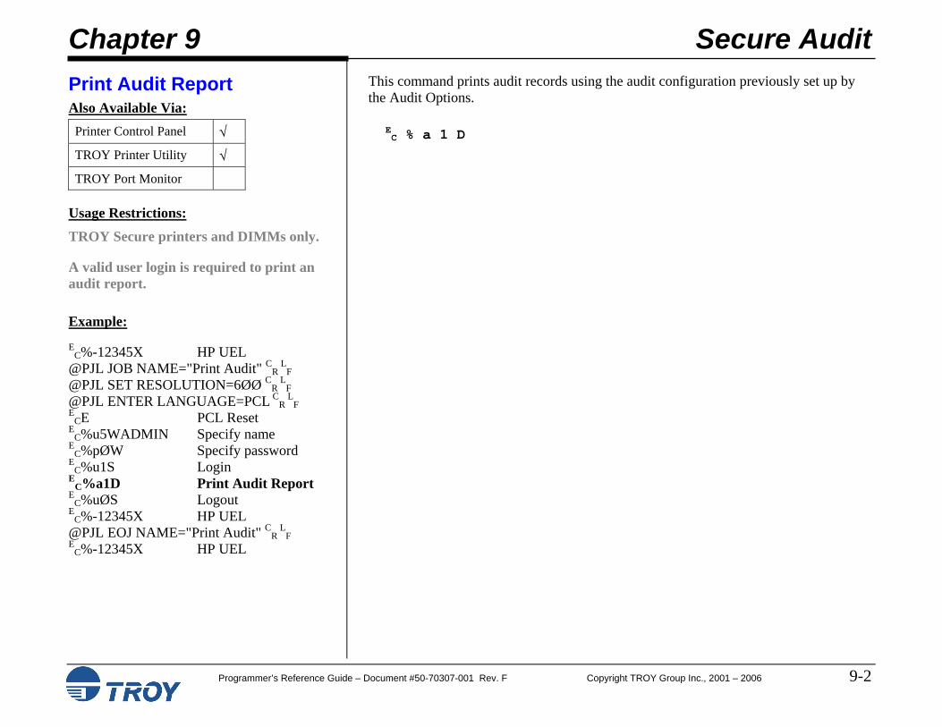
Chapter 9 – Secure Audit This chapter describes how to enable audit data collection, how to programmatically print an audit report (based upon the settings configured in Chapter 8: Audit Options) and how to delete audit records from the TROY flash-file system.
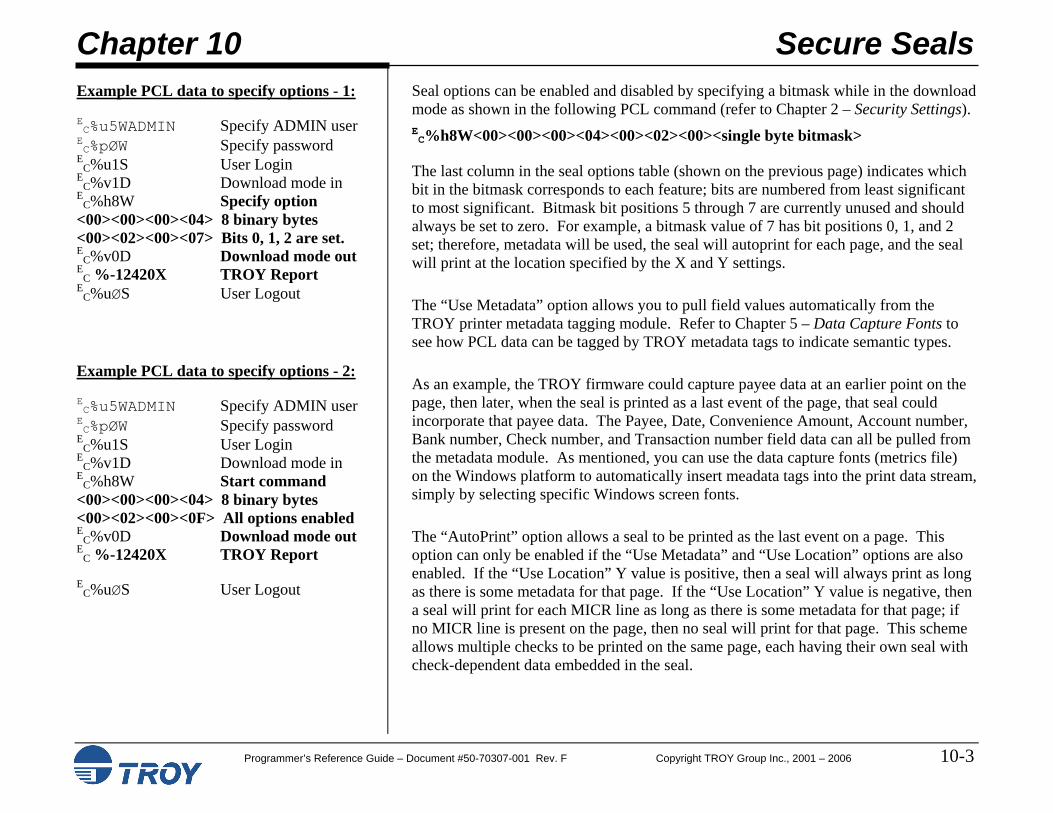
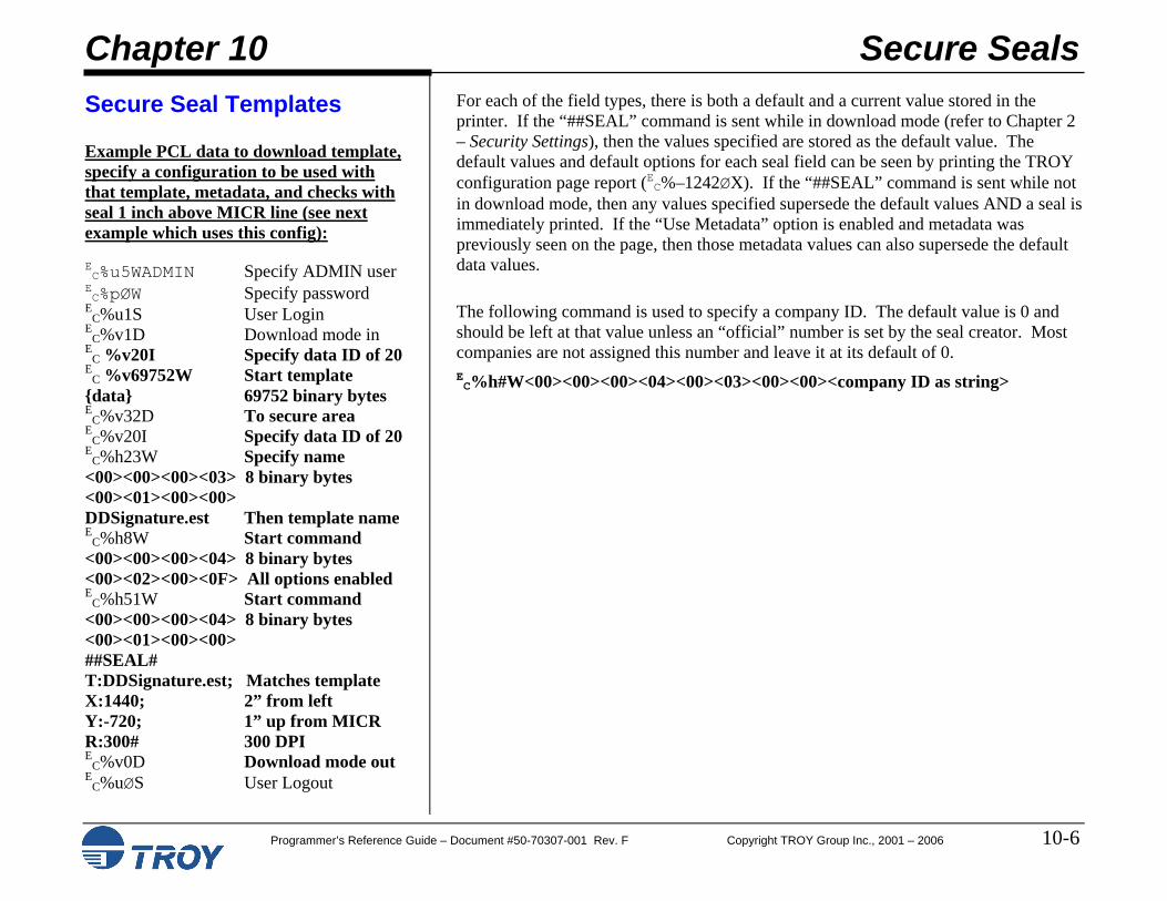
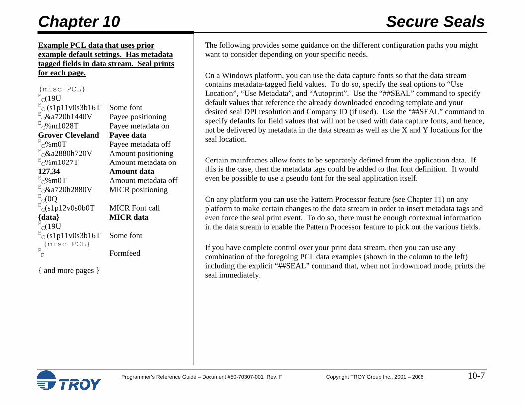
Chapter 10 – Secure Seals This chapter describes the use and implementation of the Secure Seal feature, which enables the TROY printer to print a security seal on the face of a check. The printed seal contains encoded check information (i.e., payee name, date, check number, etc.) that can only be read when the seal is scanned and decoded by the check processor.
Chapter 11 – Pattern Processing This chapter describes the Pattern Processing feature, which enables the TROY printer firmware to parse the print data stream for certain regular expressions, modifying the incoming data stream as specified by the substitution string.
Chapter 12 – Decryption This chapter describes the various decryption modes supported by TROY Security Printing Solutions, how to configure the printer’s symmetric key pass-phrase, how to configure the printer to only print encrypted jobs and how to configure a print job to be decrypted.
Chapter 13 – Printer-Specific Features This chapter describes various features that are available only on specific printer models. As of this publishing, this list of printer-specific features includes the TROY 2200 printer’s page counting system for toner low warnings.
Preface
Programmer’s Reference Guide – Document #50-70307-001 Rev. F Copyright TROY Group Inc., 2001 – 2006 Preface-8
Chapter Summaries (cont.)
Chapter 14 – Diagnostics This chapter describes internal diagnostics capabilities available in TROY Security Printing Solutions. Job routing and the ability to print hexadecimal listings of print jobs is described.
Preface
Programmer’s Reference Guide – Document #50-70307-001 Rev. F Copyright TROY Group Inc., 2001 – 2006 Preface-9
Related Documentation
TROY Security Printing User’s Guide (Available on the TROY Security Printing
Solutions CD)
TROY Quick-Start Guide (Available on the TROY Security Printing
Solutions CD)
TROY MICR Basics Handbook (Available on the TROY Security Printing
Solutions CD)
PCL 5 Printer Language – Technical Reference Guide
(Available from the Hewlett Packard Co.)
PCL 5 Comparison Guide (Available from the Hewlett Packard Co.)
Printer Job Language - Technical Reference Manual
(Available from the Hewlett Packard Co.)
The following related manuals provide additional information about TROY Security Printing Solutions, including their features and functions.
This document contains extensive information on the installation, configuration, operation, and maintenance of the TROY Security Printing Solutions.
This document provides experienced users with a fast method for installing and configuring TROY Security Printing Solutions, including setting up a PC with the relevant Microsoft Windows printer driver and configuration files for TROY fonts.
This document defines how to create a check compatible with the ANSI X/9B Committee’s recommendations for bank clearing.
This document defines the PCL 5e programming language.
This document contains updates to the PCL 5e printer language, specific to Hewlett-Packard printer models.
This document defines the PJL programming language.
Preface
Programmer’s Reference Guide – Document #50-70307-001 Rev. F Copyright TROY Group Inc., 2001 – 2006 Preface-10
How To Use This Guide
This guide is organized into chapters of relevant information. Each page within each chapter is laid out to view on-screen and many items are linked together for easy navigation. The following diagram illustrates the format of all pages in this guide.
The left-hand column defines the usage of each command and provides an example of how each command would appear in a file. Comments are noted to the right of example commands. The right-hand column presents detailed information about the command and supporting illustrations as applicable. The escape character (decimal 27, hexadecimal Øx1B) is abbreviated “E
C” throughout this manual.
Chapter 1 Introduction
Programmer’s Reference Guide – Document #50-70307 Rev. F Copyright TROY Group Inc., 2001 – 2006 1-1
TROY Security Printing Solutions
TROY Group, Inc. offers a line of Security Printing Solutions delivering varying levels of operational and secure check-printing capabilities. Throughout this document references are made to product features supported by specific Security Printing Solutions. The following is a summary of current TROY Security Printing Solutions.
TROY MICR Font DIMM/Memory Card: designed for use in selected Hewlett-Packard LaserJet printers, the TROY MICR Font DIMM/Memory Card features an enhanced collection of MICR, OCR (Optical Character Recognition), barcode, and security fonts designed for printing financial documents. None of the operational or security features listed in this guide pertain to this product. This product can be added to a standard Hewlett Packard printer.
TROY MICR Secure Font DIMM/Memory Card: designed for use in selected Hewlett-Packard LaserJet printers, the TROY MICR Secure DIMM/Memory Card contains all the features of the TROY MICR Font DIMM/Memory Card, plus print file decryption, auditing, and printer-based security PINs, user names and passwords, and a flash-file system for storing of printing resources such as company logos, electronic forms, and custom fonts.
TROY MICR Printer: a Hewlett-Packard printer pre-configured with the TROY MICR DIMM/Memory Card, plus TROY’s MICR toner sensing system, a TROY MICR toner cartridge, and optional paper tray locks. This product is designed for printing high-quality MICR documents and utilizes several convenient, easy-to-use operational features, including a flash-file system for storage of printing resources such as company logos, electronic forms, and custom fonts.
TROY MICR Secure Printer: a Hewlett-Packard printer pre-configured with the TROY MICR Secure DIMM/Memory Card (described above), plus TROY’s MICR toner sensing system, a TROY MICR toner cartridge, and optional paper tray locks. This product is designed for the secure printing of high-quality MICR documents and utilizes several convenient, easy-to-use operational and security features, including a flash-file system for storage of printing resources such as company logos, electronic forms, and custom fonts.
Chapter 1 Introduction
Programmer’s Reference Guide – Document #50-70307 Rev. F Copyright TROY Group Inc., 2001 – 2006 1-2
TROY Security Printing Solutions (cont.)
TROY MICR Secure EX Printer: a Hewlett-Packard printer pre-configured with the TROY MICR Secure DIMM/Memory Card (described on the previous page), plus TROY’s MICR toner sensing system, a TROY MICR toner cartridge, a printer keylock switch, input paper tray locks, and also includes the TROYmark feature, AutoProtect font, and Secure Seal technology. This top-of-the-line product is designed for the secure printing of high-quality MICR documents and utilizes several convenient, easy-to-use operational and security features, including a flash-file system for storage of printing resources such as company logos, electronic forms, and custom fonts.
TROY IRD Printer – a Hewlett-Packard printer pre-configured with the TROY MICR DIMM/Memory Card (described on previous page), plus TROY’s MICR toner sensing system, a TROY MICR toner cartridge, a duplexer, and optional paper tray locks. This product is designed for printing high-quality IRD MICR documents and utilizes several convenient, easy-to-use operational features, including a flash-file system for storage of printing resources such as company logos, electronic forms, and custom fonts.
TROY IRD Secure EX Printer – a Hewlett-Packard printer pre-configured with the TROY MICR Secure Memory Card (described on previous page), plus TROY’s MICR toner sensing system, a TROY MICR toner cartridge, a printer keylock switch, input paper tray locks, a duplexer, and also includes the TROYmark feature, AutoProtect font, and Secure Seal technology. This top-of-the-line product is designed for the secure printing of high-quality IRD MICR documents and utilizes several convenient, easy-to-use operational and security features, including a flash-file system for storage of printing resources such as company logos, electronic forms, and custom fonts.
TROY IRD 9050 1UP / IRD 9050 1UP Secure EX Printer – contains the features of the TROY MICR 9050 printer and has the additional ability to print IRD 1-up forms using a specially redesigned TROY IRD duplexer and TROY IRD paper trays designed to accommodate both forward and return single IRD forms. The printer also includes a 100-sheet multipurpose tray for printing test and configuration pages using standard size paper. The Secure EX model includes the addition of paper tray locks, a printing enable/disable lock switch, and additional security features designed to enhance printing security.
Chapter 1 Introduction
Programmer’s Reference Guide – Document #50-70307 Rev. F Copyright TROY Group Inc., 2001 – 2006 1-3
Printer Security States
To help maintain a secure MICR printing environment, TROY Security Printing Solutions have security features that, in combination, create security states. The interdependency of these security states ensures the integrity of the MICR printing security features, which can be enabled and/or configured to meet your specific security requirements. These features can be accessed through the TROY Printer Utility or the printer control panel, as well as through programming commands included in this guide.
When a MICR print job is sent to the printer, the printer firmware monitors up to five security states to determine if the pre-defined set of conditions are correct to allow the MICR job to print. The five security features include the following:
MICR Mode: MICR mode must be enabled to allow the printing of MICR documents. If disabled, the printer will not print valid MICR lines.
Login Status (not supported in MICR printer and MICR Font DIMM): Two types of logins are supported – administrator and user. If user logins are implemented, the printer requires a valid user login before gaining access to any of the printer’s secure resources.
Printer and MICR PINs (not supported in MICR printer and MICR Font DIMM/Memory Card): Electronic print locks allow the printer’s secure resources to be electronically locked (allowing only non-MICR documents to print), or the printer can be completely disabled (no documents will print) without the user entering the matching PIN number at the printer control panel.
Keylock Position (Secure EX Printers Only): The three-position keylock allows the printer’s secure resources to be physically locked (allowing only non-MICR documents to print), or the printer can be completely disabled (no documents will print).
MICR Toner Cartridge Sensing: Prevents the printing of MICR documents with standard (non-MICR) toner by sensing the presence of a TROY MICR toner cartridge.
NOTE: See the table in Section 2 of the TROY Security Printing Solutions User’s Guide for a list of features that are dependent on various combinations of printer security states.
Chapter 1 Introduction
Programmer’s Reference Guide – Document #50-70307 Rev. F Copyright TROY Group Inc., 2001 – 2006 1-4
Properly Formed Jobs Example 1 – PJL Job Wrapping:
{PJL wrapper header} E
C%-12345X HP PJL UEL @PJL JOB NAME="Sample" CR
LF
@PJL SET RESOLUTION=6ØØ CR L
F @PJL ENTER LANGUAGE=PCLC
RL
F E
CE PCL Reset
{Your PCL here}
{PJL wrapper trailer} E
C%-12345X HP PJL UEL @PJL EOJ NAME="Sample" CR
LF
EC%-12345X HP PJL UEL
Example 2 – Proper PCL Page Form:
{PJL wrapper header from above} E
C&u6ØØD Set printer and PCL E
C*t6ØØR resolution to 600 dpi E
C&lØO Set page orientation E
C&l7H Set paper tray
{First page PCL here} E
C&lØH Print first page E
C&lØO Set page orientation EC&l7H Set paper tray
{Next or last page PCL here} EC&lØH Print next/last page
{PJL wrapper trailer from above}
Recent changes in how Hewlett Packard LaserJet printers manage print jobs makes it more important than ever that you create well formed print jobs for TROY Security Printing Solutions. Please follow these rules and workflow when creating print jobs.
NOTE: Throughout this guide examples may be shown with or without their associated print job command wrappers. If no print job wrapper is listed, this is done solely to increase readability of this guide. Always wrap print jobs as indicated below.
Hewlett Packard’s Printer Job Language (PJL) provides both printer configuration control as well as print job definition for all print data streams. By defining the start and end of each print job using PJL commands you can be assured your TROY Security Printing Solution will properly print all files it receives. This is known as wrapping the job in PJL (see Example 1 to the left).
The example to the left shows the proper way to wrap any print job sent to a TROY MICR printer.
Example 2 on the left shows the proper way to begin all PCL 5e print streams and would be inserted in the PJL from the previous example where the words Your PCL here appear. It is recommended you repeat the page orientation and paper tray selection commands at the top of each page, affording the maximum flexibility for printed document styles and content.
NOTE: All PCL 5e print jobs should be printed at 600 dpi to ensure optimum secure font appearance.
NOTE: You should never use the FF character or the EC E PCL Reset command to terminate pages. Always use the EC&lØH command to denote the end of any PCL 5e page.
Chapter 1 Introduction
Programmer’s Reference Guide – Document #50-70307 Rev. F Copyright TROY Group Inc., 2001 – 2006 1-5
Default and Temporary Printer Settings Example: EC%u5WADMIN Specify name
This is an example of the structure of a print job to change default settings in a TROY Security Printing Solution. Notice the matching pairs of Login/Logout and Enter/Exit download mode commands.
Example:
EC%u5WUSER1 Specify name
EC%pØW Specify password
EC%u1S Login
. . Job-specific cmds . EC%uØS Logout
This is a sample print job structure containing job-specific commands.
Each feature of a TROY Security Printing Solution has a default setting stored within the printer. These default settings determine how each printer feature will function when a print job is sent to the printer. The administrator can change the default settings to meet the needs of a variety of MICR printing environments using the TROY Printer Utility or the printer control panel. These settings can also be changed programmatically using the TROY PCL 5 extension commands described in this guide.
Changing the default settings within a TROY Security Printing Solution requires the administrator or a program to login to the printer using the administrator login and place the printer in what is called download mode. (A user cannot login and place the printer in download mode.) When in download mode, the printer stores changes to printer settings in the printers non-volatile memory and makes those changed settings active for the current and all subsequent print jobs.
Other features can only be accessed by an administrator login, even though they will not result in changes to the printer settings.
There are also a number of features that can be accessed by providing a user login. Such features can be varied on a print job by print job basis. Temporarily changing the MICR mode or default paper tray mappings are examples of job-specific features. After each print job has completed printing, all feature settings return to their default values.
The tables on the following pages (except for the Fonts table) indicate which commands can only be sent to a printer when it is in download mode, which commands may be sent to a printer that is explicitly not in download mode (job-specific), and which commands can be sent to a printer in either mode (both).
Chapter 1 Introduction
Programmer’s Reference Guide – Document #50-70307 Rev. F Copyright TROY Group Inc., 2001 – 2006 1-6
Quick Reference Tables
The following tables summarize all TROY extensions to the PCL 5e printer language. Each entry is linked to the page in this guide containing details about the command.
TROY Security Fonts
Function TROY
Solution
PCL 5e Extension Command E-13B MICR Font (Legacy TROY solutions) All
EC(ØQ
EC(sØp8.ØØh8.8vØsØbØT
E-13B MICR Font (Current TROY solutions) All
EC(ØQ
EC(s1p12.ØØvØsØbØT
CMC-7 MICR Font (Legacy TROY solutions) All
EC(ØQ
EC(sØp8.ØØh8.8vØsØb1T
CMC-7 MICR Font (Current TROY solutions) All
EC(ØQ
EC(s1p12.ØØvØsØb1T
OCR-A Font All EC(ØO
EC(s1p□vØsØb1Ø4T
OCR-B Font All EC(1O
EC(s1p□vØsØb11ØT
TROY Auto Protect Font All EC(19U
EC(s1p□vØsØb166Ø2T EC%m1I
TROY Micro Print Font All EC(1ØU
EC(sØp8Ø.ØhØ.8vØsØbØT
TROY Reverse Helvetica Font All
EC(9U
EC(s1p□vØs33b2458ØT
TROY Security Font All EC(4Q
EC(s1p□vØsØbØT
Enhanced Convenience Font All EC(3Q
EC(s1p18.ØvØsØbØT
Large Convenience Font All EC(1Q
EC(sØp5.Øh16.ØvØsØbØT
Small Convenience Font All EC(2Q
EC(sØp6.ØØh22.ØvØsØbØT
□ = desired point size
Chapter 1 Introduction
Programmer’s Reference Guide – Document #50-70307 Rev. F Copyright TROY Group Inc., 2001 – 2006 1-7
Quick Reference Tables (cont.)
International Security Fonts
Function
TROY Solution
PCL 5e Extension Command
TROY Security Font (Spanish) All
EC(4Q
EC(s1p□vØsØb4T
Large Convenience Font (British) All
EC(1Q
EC(sØp5.14h16.Ø9vØsØb1T
Small Convenience Font (British) All
EC(2Q
EC(sØp6h22.68vØsØb1T
Large Convenience Font (French) All
EC(1Q
EC(sØp5.14h16.Ø9vØsØb2T
Small Convenience Font (French) All
EC(2Q
EC(sØp6h22.68vØsØb2T
Large Convenience Font (Italian) All
EC(1Q
EC(sØp5.14h16.Ø9vØsØb3T
Small Convenience Font (Italian) All
EC(2Q
EC(sØp6h22.68vØsØb3T
Large Convenience Font (Spanish) All
EC(1Q
EC(sØp5.14h16.Ø9vØsØb4T
Small Convenience Font (Spanish) All
EC(2Q
EC(sØp6h22.68vØsØb4T
□ = desired point size
NOTE: International security fonts must be installed into the TROY flash-file system DIMM using the TROY Printer Utility. The fonts files are located on the TROY Security Printing Solutions CD in the \Intl folder.
Chapter 1 Introduction
Programmer’s Reference Guide – Document #50-70307 Rev. F Copyright TROY Group Inc., 2001 – 2006 1-8
Quick Reference Tables (cont.)
Chapter 2 – Security Settings
Function
TROY Solution
Command Availability
PCL 5e Extension
Specify Name All Both EC%u#W data
Specify Password All Both EC%p#W data
Login All Both EC%u1S
Logout All Both EC%uØS
Enter Download Mode All Download EC%v1D
Exit Download Mode All Download EC%vØD
Printer Lock PIN All Secure Download EC%l#W data
MICR Lock PIN All Secure Download EC%m#W data
Job Name and PIN All Secure Download (See Chapter 2)
Toner Sensor Response All Printers Download EC%t#E
Add User All Secure Download EC%u2S
Delete User All Secure Download EC%u3S
Change Password All Download EC%u4S
Delete All Users All Secure Download EC%u5S
Print User List All Download EC%u–1S
Chapter 1 Introduction
Programmer’s Reference Guide – Document #50-70307 Rev. F Copyright TROY Group Inc., 2001 – 2006 1-9
Quick Reference Tables (cont.)
Chapter 3 – Printing Control
Function
TROY Solution
CommandAvailability
PCL 5e Extension
MICR Mode Enable All Both EC%-124ØØX
MICR Mode Disable All Both EC%-124Ø1X
Print E-13B Quality Document All Both EC%-124Ø3X
Print CMC-7 Quality Document All Both EC%-124Ø4X
Print Configuration Page All Both EC%-1242ØX
Printer Type All Download EC%t#X
Remap Paper Tray All Both EC%i#T
Specify Paper Trap Mapping All Download EC%i#W data
Alternate Escape Character All Both EC%e#W data
Alternate Command Set (Optional) Download EC%i#E
ExPT Image Offset X All Download EC%o#I
ExPT Image Offset Y All Download EC%o#J
ExPT MICR Line Offset X All Download EC%o#M
ExPT MICR Line Offset Y All Download EC%o#N
Automatic Page Rotation All Both EC%o#R
Languages Supported All Secure Download EC%l#T
Chapter 1 Introduction
Programmer’s Reference Guide – Document #50-70307 Rev. F Copyright TROY Group Inc., 2001 – 2006 1-10
Quick Reference Tables (cont.)
Chapter 4 – Secure and Public Resources
Function
TROY Solution
CommandAvailability
PCL 5e Extension
Add Public Font All Download EC*c4F
Add Secure Font All Secure Download EC*c5F
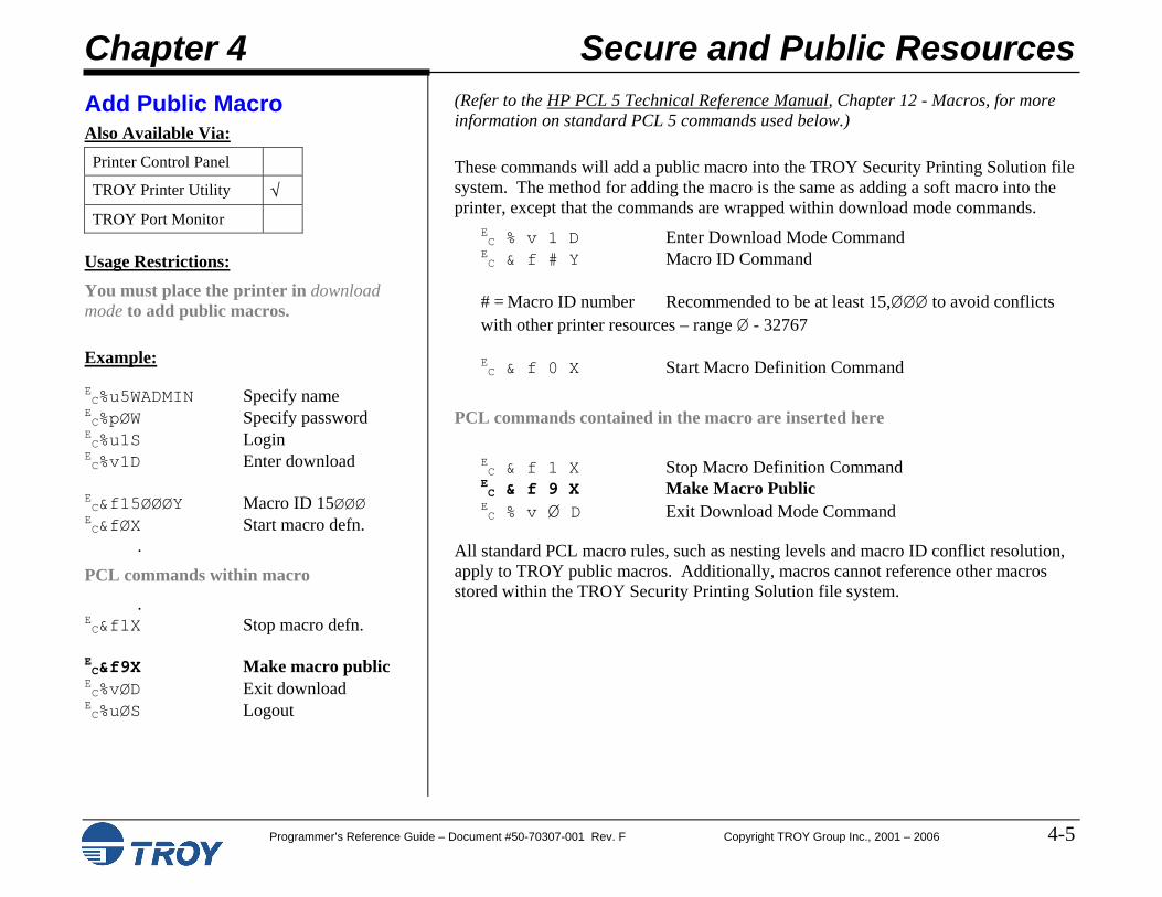
Add Public Macro All Download EC&f9X
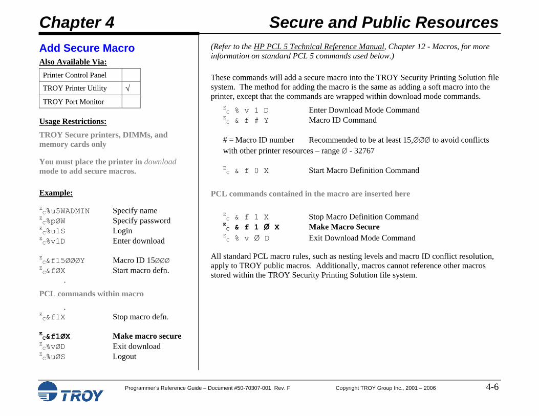
Add Secure Macro All Secure Download EC&f1ØX
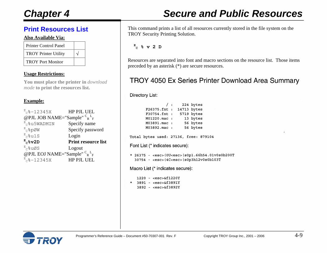
Print Resource List All Download EC%v2D
Delete All Public Resources All Download EC%v7D
Delete All Secure Resources All Secure Download EC%v8D
Delete All Resources All Secure Download EC%v9D
Delete All Public Fonts All Download EC%v1ØD
Delete All Secure Fonts All Secure Download EC%v11D
Delete All Fonts All Secure Download EC%v12D
Delete All Public Macros All Download EC%v13D
Delete All Secure Macros All Secure Download EC%v14D
Delete All Macros All Secure Download EC%v15D
Chapter 5 – Data Capture Fonts
Function
TROY Solution
CommandAvailability
PCL 5e Extension
Data Capture Type All Secure Job-specific EC%m#T
Invisible Print Data Secure EX Job-specific EC%m#I
Chapter 1 Introduction
Programmer’s Reference Guide – Document #50-70307 Rev. F Copyright TROY Group Inc., 2001 – 2006 1-11
Quick Reference Tables (cont.)
Chapter 6 – Barcode Fonts
Function
TROY Solution
PCL 5e Extension Command
UPC - A All EC(8Y
EC(s1p□vØsØb246ØØT
UPC - E All EC(8Y
EC(s1p□vØsØb2461ØT
EAN - 8 All EC(8Y
EC(s1p□vØsØb2462ØT
EAN - 13 All EC(8Y
EC(s1p□vØsØb2463ØT
Interleaved 2 of 5 All EC(4Y
EC(s1p□vØsØb2464ØT
Code 39 (3 of 9) All EC(ØY
EC(s1p□vØsØb2467ØT
Code 128 All EC(ØY
EC(s1p□vØsØb247ØØT
POSTNET All EC(15Y
EC(s1p□vØsØb2477ØT
Reverse POSTNET All EC(ØY
EC(s1p□vØs33b2477ØT
□ = desired point size
Chapter 1 Introduction
Programmer’s Reference Guide – Document #50-70307 Rev. F Copyright TROY Group Inc., 2001 – 2006 1-12
Programmer’s Reference Guide – Document #50-70307 Rev. F Copyright TROY Group Inc., 2001 – 2006 1-13
Quick Reference Tables (cont.)
TROY Fonts for Code 128 (cont.)
Char Set A Char Set B Char Set C Index TROY Character Set ASCII ASCII Value Value Decimal ASCII Hex > > 30 30 62 > 3E ? ? 31 31 63 ? 3F @ @ 32 32 64 @ 40 A A 33 33 65 A 41 B B 34 34 66 B 42 C C 35 35 67 C 43 D D 36 36 68 D 44 E E 37 37 69 E 45 F F 38 38 70 F 46 G G 39 39 71 G 47 H H 40 40 72 H 48 I I 41 41 73 I 49 J J 42 42 74 J 4A K K 43 43 75 K 4B L L 44 44 76 L 4C M M 45 45 77 M 4D N N 46 46 78 N 4E O O 47 47 79 O 4F P P 48 48 80 P 50 Q Q 49 49 81 Q 51 R R 50 50 82 R 52 S S 51 51 83 S 53 T T 52 52 84 T 54 U U 53 53 85 U 55 V V 54 54 86 V 56 W W 55 55 87 W 57 X X 56 56 88 X 58 Y Y 57 57 89 Y 59 Z Z 58 58 90 Z 5A
Chapter 1 Introduction
Programmer’s Reference Guide – Document #50-70307 Rev. F Copyright TROY Group Inc., 2001 – 2006 1-14
Quick Reference Tables (cont.)
TROY Fonts for Code 128 (cont.)
Char Set A Char Set B Char Set C Index TROY Character Set ASCII ASCII Value Value Decimal ASCII Hex [ [ 59 59 91 [ 5B \ \ 60 60 92 \ 5C ] ] 61 61 93 ] 5D 62 62 94 ^ 5E _ _ 63 63 95 _ 5F NUL ` 64 64 96 ` 60 SOH a 65 65 97 a 61 STX b 66 66 98 b 62 ETX c 67 67 99 c 63 EOT d 68 68 100 d 64 ENQ e 69 69 101 e 65 ACK f 70 70 102 f 66 BEL g 71 71 103 g 67 BS h 72 72 104 h 68 HT i 73 73 105 i 69 LP j 74 74 106 j 6A VT k 75 75 107 k 6B FF l 76 76 108 l 6C CR m 77 77 109 m 6D SO n 78 78 110 n 6E SI o 79 79 111 o 6F DLE p 80 80 112 p 70 DC1 q 81 81 113 q 71 DC2 r 82 82 114 r 72 DC3 s 83 83 115 s 73 DC4 t 84 84 116 t 74 NAK u 85 85 117 u 75 SYN v 86 86 118 v 76 ETB w 87 87 119 w 77
Chapter 1 Introduction
Programmer’s Reference Guide – Document #50-70307 Rev. F Copyright TROY Group Inc., 2001 – 2006 1-15
Quick Reference Tables (cont.)
TROY Fonts for Code 128 (cont.)
Char Set A Char Set B Char Set C Index TROY Character Set ASCII ASCII Value Value Decimal ASCII Hex CAN x 88 88 120 x 78 EM y 89 89 121 y 79 SUB z 90 90 122 z 7A ESC { 91 91 123 { 7B FS | 92 92 124 | 7C GS } 93 93 125 } 7D RS ~ 94 94 126 ~ 7E US DEL 95 95 127 DEL 7F FNC3 FNC3 96 96 128 80 FNC2 FNC2 97 97 129 81 Shift Shift 98 98 130 82 Code C Code C 99 99 131 83 Code B FNC4 Code B 100 132 IND 84 FNC4 Code A Code A 101 133 NEL 85 FNC1 FNC1 FNC1 102 134 SSA 86
Start A Start A Start A 103 135 ESA 87 Start B Start B Start B 104 136 HTS 88 Start C Start C Start C 105 137 HTJ 89 Stop Stop Stop 106 138 VTS 8A
NOTE: ASCII characters beyond the decimal value of 127 are not printable characters and are not typically used within the Code 128 barcode.
Chapter 1 Introduction
Programmer’s Reference Guide – Document #50-70307 Rev. F Copyright TROY Group Inc., 2001 – 2006 1-16
Quick Reference Tables (cont.)
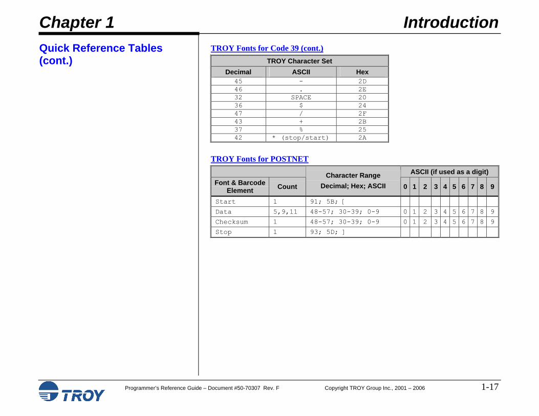
TROY Fonts for Code 39
TROY Character Set Decimal ASCII Hex
48 0 30 49 1 31 50 2 32 51 3 33 52 4 34 53 5 35 54 6 36 55 7 37 56 8 38 57 9 39 65 A 41 66 B 42 67 C 43 68 D 44 69 E 45 70 F 46 71 G 47 72 H 48 73 I 49 74 J 4A 75 K 4B 76 L 4C 77 M 4D 78 N 4E 79 O 4F 80 P 50 81 Q 51 82 R 52 83 S 53 84 T 54 85 U 55 86 V 56 87 W 57 88 X 58 89 Y 59 90 Z 5A
Chapter 1 Introduction
Programmer’s Reference Guide – Document #50-70307 Rev. F Copyright TROY Group Inc., 2001 – 2006 1-17
Programmer’s Reference Guide – Document #50-70307 Rev. F Copyright TROY Group Inc., 2001 – 2006 1-18
Quick Reference Tables (cont.)
TROY Fonts for EAN 13, EAN 8, UPC-A, and UPC-E ASCII (if used as a digit) Font and Barcode
Element Ct Character Range
(Dec; Hex; ASCII) 0 1 2 3 4 5 6 7 8 9
EAN 13 Visual system number, left guard
1 97-106; 61-6A; a-j
a b c d e f g h i j
Left side odd parity 48-57; 30-39; 0-9 0 1 2 3 4 5 6 7 8 9
Left side even parity
6 75-84; 4B-54; K-T K L M N O P Q R S T
Middle guard 1 109; 6D; m
Right side even parity 6 65-74; 41-4A; A-J A B C D E F G H I J
Right guard 1 93; 5D; ]
EAN 8 Start guard 1 91; 5B; [
Left side odd parity 4 48-57; 30-39; 0-9 0 1 2 3 4 5 6 7 8 9
Middle guard 1 109; 6D; M
Right side even parity 4 65-74; 41-4A; A-J A B C D E F G H I J
Right guard 1 93; 5D; ]
UPC-A Visual system number, left guard, left side odd parity system number
1 97-106; 61-6A; a-j
a b c d e f g h i J
Left side odd parity 5 48-57; 30-39; 0-9 0 1 2 3 4 5 6 7 8 9
Middle guard 1 109; 6D; m
Right side even parity 5 65-74; 41-4A; A-J A B C D E F G H I J
Right side even parity checksum, right guard, visual checksum
1 110-119; 6E-77; n-w
n o p q r s t u v w
UPC-E Visual system number, left guard
1 97-106; 61-6A; a-j
a b c d e f g h i J
Left side odd parity 48-57; 30-39; 0-9 0 1 2 3 4 5 6 7 8 9
Left side even parity
6 65-74; 41-4A; A-J A B C D E F G H I J
Right guard, visual checksum
1 110-119; 6E-77; n-w
n o p q r s t u v w
Chapter 1 Introduction
Programmer’s Reference Guide – Document #50-70307 Rev. F Copyright TROY Group Inc., 2001 – 2006 1-19
Quick Reference Tables (cont.)
Chapter 7 – TROYmark™ Settings
Function
TROY Solution
CommandAvailability
PCL 5e Extension
TROYmark Control Secure EX Job-specific EC%w#M
TROYmark Regions Secure EX Job-specific EC%w#B
Region Anchor X Secure EX Job-specific EC%w#X
Region Anchor Y Secure EX Job-specific EC%w#Y
Region Width Secure EX Job-specific EC%w#H
Region Height Secure EX Job-specific EC%w#V
Specify TROYmark Pattern Secure EX Download EC%w#P
Download TROYmark Pattern Secure EX Download EC%w#W data
Chapter 8 – Audit Options
Function
TROY Solution
CommandAvailability
PCL 5e Extension
Sort By All Secure Download EC%a#S
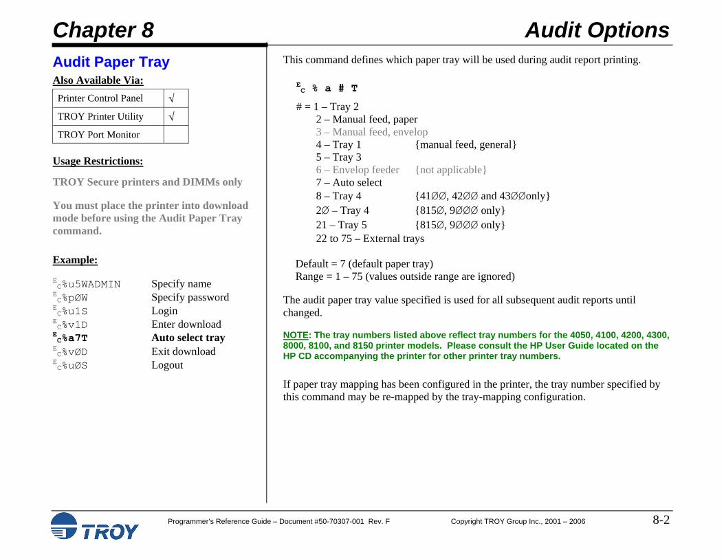
Audit Paper Tray All Secure Download EC%a#T
Print Range Recent All Secure Download EC%a11E
Print Range All All Secure Download EC%a12E
Report Type Summary All Secure Download EC%a13E
Report Type Detailed All Secure Download EC%a14E
Sort Order Ascending All Secure Download EC%a15E
Sort Order Descending All Secure Download EC%a16E
Auto Delete Disable All Secure Download EC%a3ØE
Auto Delete Enable All Secure Download EC%a31E
Auto Report Disable All Secure Download EC%a32E
Auto Report Enable All Secure Download EC%a33E
Chapter 1 Introduction
Programmer’s Reference Guide – Document #50-70307 Rev. F Copyright TROY Group Inc., 2001 – 2006 1-20
Quick Reference Tables (cont.)
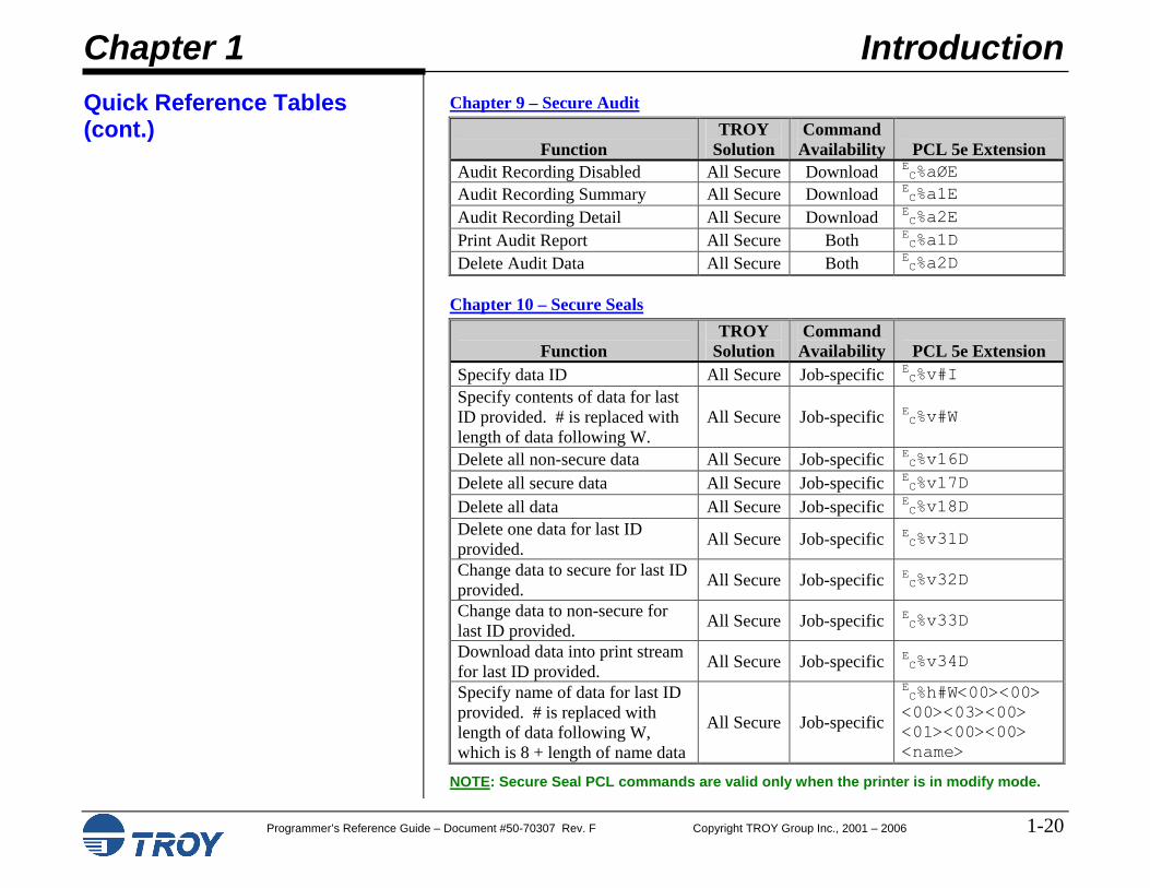
Chapter 9 – Secure Audit
Function
TROY Solution
CommandAvailability
PCL 5e Extension
Audit Recording Disabled All Secure Download EC%aØE
Audit Recording Summary All Secure Download EC%a1E
Audit Recording Detail All Secure Download EC%a2E
Print Audit Report All Secure Both EC%a1D
Delete Audit Data All Secure Both EC%a2D
Chapter 10 – Secure Seals
Function TROY
Solution Command
Availability
PCL 5e Extension Specify data ID All Secure Job-specific E
C%v#I Specify contents of data for last ID provided. # is replaced with length of data following W.
All Secure Job-specific EC%v#W
Delete all non-secure data All Secure Job-specific EC%v16D
Delete all secure data All Secure Job-specific EC%v17D
Delete all data All Secure Job-specific EC%v18D
Delete one data for last ID provided. All Secure Job-specific E
C%v31D
Change data to secure for last ID provided. All Secure Job-specific E
C%v32D
Change data to non-secure for last ID provided. All Secure Job-specific E
C%v33D
Download data into print stream for last ID provided. All Secure Job-specific E
C%v34D
Specify name of data for last ID provided. # is replaced with length of data following W, which is 8 + length of name data
All Secure Job-specific
EC%h#W<00><00> <00><03><00> <01><00><00> <name>
NOTE: Secure Seal PCL commands are valid only when the printer is in modify mode.
Chapter 1 Introduction
Programmer’s Reference Guide – Document #50-70307 Rev. F Copyright TROY Group Inc., 2001 – 2006 1-21
Quick Reference Tables (cont.)
Secure Seal Field Descriptions
Field Letter
Field Name Field Type Max Size
Description
T Template Name alphanumeric 80 Encoding template name as stored in TROY NV area.
P Payee Name alphanumeric 32 Payee name
V Check Value numeric 16 Dollar value of the check (includes optional decimal point)
A Account # numeric 20 Account number of the checking account
B Routing # numeric 20 Routing number of the bank
D Date numeric 20 Date of the check (YYYYMMDD, YYYY/MM/DD, or DD/MM/YYYY)
N Transaction # numeric 20 Transaction number of the check
C Check # numeric 20 Check number
X X Location numeric 6 Specifies X location of the seal if the seal option “Use Location” is enabled. Units are 1/720” (decipoints).
Y Y Location numeric 6 Specified Y location of the seal if the seal option “Use Location” is enabled. Units are 1/720” (decipoints).
R Resolution numeric 3 Designates seal print resolution in DPI. Must be one of 75, 100, 150, 200, 300 (default), or 600.
Chapter 1 Introduction
Programmer’s Reference Guide – Document #50-70307 Rev. F Copyright TROY Group Inc., 2001 – 2006 1-22
Quick Reference Tables (cont.)
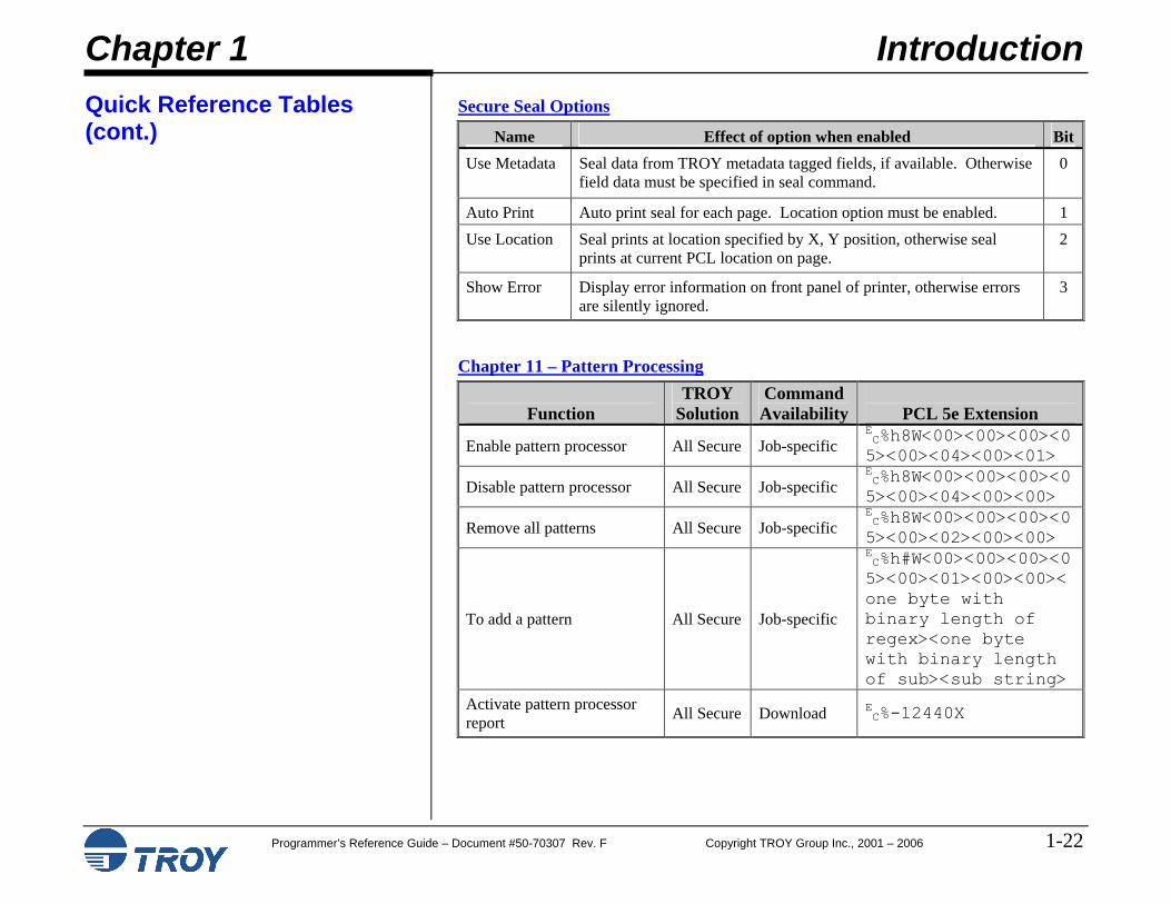
Secure Seal Options
Name Effect of option when enabled Bit Use Metadata Seal data from TROY metadata tagged fields, if available. Otherwise
field data must be specified in seal command. 0
Auto Print Auto print seal for each page. Location option must be enabled. 1 Use Location Seal prints at location specified by X, Y position, otherwise seal
prints at current PCL location on page. 2
Show Error Display error information on front panel of printer, otherwise errors are silently ignored.
3
Chapter 11 – Pattern Processing
Function
TROY Solution
CommandAvailability
PCL 5e Extension
Enable pattern processor All Secure Job-specific EC%h8W<00><00><00><05><00><04><00><01>
Disable pattern processor All Secure Job-specific EC%h8W<00><00><00><05><00><04><00><00>
Remove all patterns All Secure Job-specific EC%h8W<00><00><00><05><00><02><00><00>
To add a pattern All Secure Job-specific
EC%h#W<00><00><00><05><00><01><00><00><one byte with binary length of regex><one byte with binary length of sub><sub string>
Activate pattern processor report All Secure Download E
C%-12440X
Chapter 1 Introduction
Programmer’s Reference Guide – Document #50-70307 Rev. F Copyright TROY Group Inc., 2001 – 2006 1-23
Quick Reference Tables (cont.)
Chapter 12 – Decryption
Function
TROY Solution
CommandAvailability
PCL 5e Extension
Decryption Password All Secure Job-specific EC%c#W data
Decryption Control All Secure Job-specific EC%c#T
Decryption Mode All Secure Download EC%c#M
Chapter 13 – Printer-Specific Features
Function
TROY Solution
CommandAvailability
PCL 5e Extension
Pages Per Cartridge All 2200 Download EC%t#L
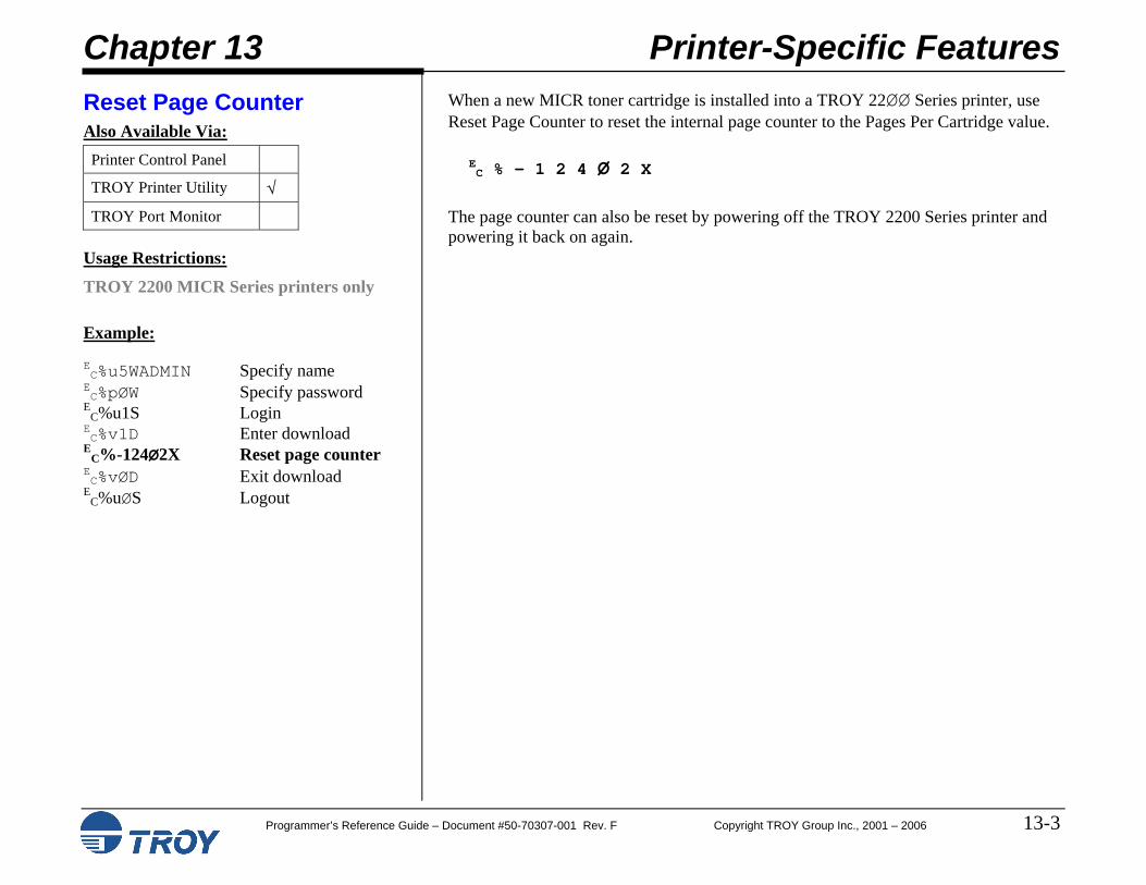
Reset Page Counter All 2200 Download EC%-124Ø2X
Disable Toner Low Warnings All 2200 Download EC%-1241ØX
Enable Toner Low Warnings All 2200 Download EC%-12411X
Chapter 14 – Diagnostics
Function TROY
Solution Command
Availability
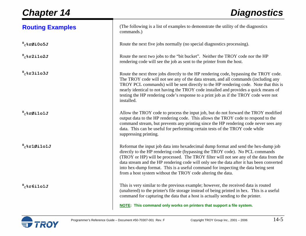
PCL 5e Extension Input Job Routing All Download E
C%r#I Output Job Routing All Download E
C%r#O Jobs To Route All Download E
C%r#J
Chapter 2 Security Settings
Programmer’s Reference Guide – Document #50-70307-001 Rev. F Copyright TROY Group Inc., 2001 - 2006 2-1
Introduction
Administrator Name and Password
An administrator password is used within the TROY Security Printing Solutions printers to secure the printer’s configuration settings. The printer uses a permanent default user name (ADMIN) that cannot be deleted or modified; however, the administrator password can be modified using the TROY Printer Utility or the printer control panel. The administrator default password is blank (no password); however, administrators are encouraged to setup a unique password to restrict access to the TROY Security Printer’s configuration settings.
NOTE: The administrator’s password is stored in the printer’s non-volatile flash memory and will remain resident even when the printer power is cycled (switched OFF and ON).
NOTE: It is the administrator’s responsibility to safeguard all name and password information, including paper printouts and the electronic name and password lists (UPL files) saved on the administrator’s computer.
Although the administrator password can be set via the printer control panel, TROY strongly recommends using the TROY Printer Utility to set or modify the administrator password. The TROY Printer Utility will automatically update the printer’s administrator password whenever the password is changed in the printer utility. However, changing the administrator password at the printer control panel will not update the TROY Printer Utility password (there is no bi-directional communication). The printer’s administrator password and the TROY Printer Utility password must be identical in order to access the printer features through the TROY Printer Utility.
NOTE: Initially, the default password for the printer is blank (no password). To maintain printer security, it is strongly recommended that the administrator change the password to prevent unauthorized access to the printer control panel.
NOTE: Some TROY Security Printing Solutions support only numeric password entry from the printer control panel. As an additional security measure, by configuring these printers with an alphanumeric password, the administrator can lock out control panel access to printer features. Refer to the User’s Guide for your TROY Security Printing Solution for further details.
Chapter 2 Security Settings
Programmer’s Reference Guide – Document #50-70307-001 Rev. F Copyright TROY Group Inc., 2001 - 2006 2-2
Introduction (cont.) User Names and Passwords (MICR Secure and MICR Secure EX models only)
This feature allows the administrator to set up to 20 user names and passwords (one administrator and 19 users) to prevent unauthorized access of the printer’s secure resources and other security features. All names and passwords are stored in the secure memory area of the printer’s memory and can be assigned and/or modified by the administrator using the TROY Printer Utility. The administrator can print a list of active user names and passwords using the TROY Printer Utility or printer control panel.
If the administrator configures a printer with one or more user names and passwords, the following list of features will only be accessible to print jobs or user requests at the control panel when a valid user name and password is used to log in.
Access to the TROY MICR fonts.
Access to all resources stored in the secure area of the printer’s flash-file system.
Changes to the MICR mode.
Disabling of the paper tray mapping set by an administrator to secure check paper in a paper tray.
Printing of audit reports and deletion of audit records.
Printing of sample reports containing MICR characters (Windows Demonstration and PCL Demonstration pages).
User names will be automatically recorded in the enhanced audit data (Secure and Secure EX printers only) for each print job initiated by a user. The system default user password is blank (no password) and not entering a user password when assigning a new user will allow that user to access the printer’s secure resources without using a password. Attempts to add duplicate users will be ignored. If you choose not to set up user names and passwords, TROY strongly recommends that administrators set up an administrator password to prevent unauthorized access to the printer features and settings from the TROY Printer Utility, the TROY Port Monitor, or the printer control panel.
Chapter 2 Security Settings
Programmer’s Reference Guide – Document #50-70307-001 Rev. F Copyright TROY Group Inc., 2001 - 2006 2-3
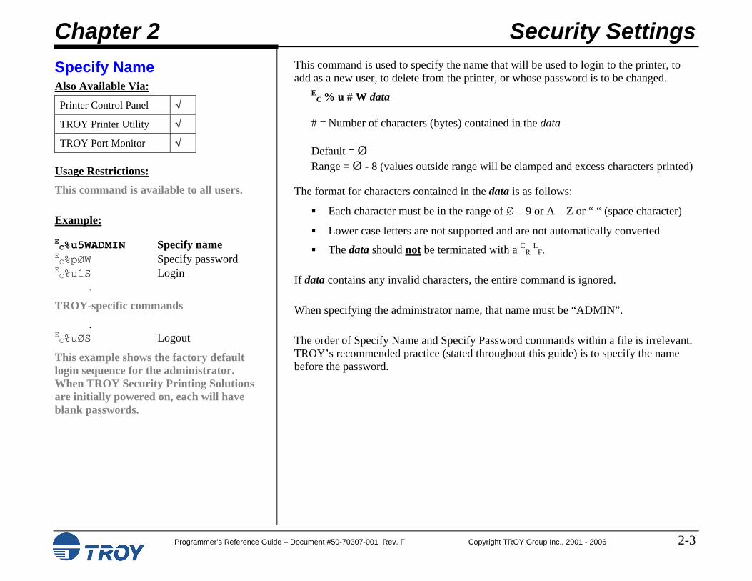
Specify Name Also Available Via: Printer Control Panel √
TROY Printer Utility √
TROY Port Monitor √
Usage Restrictions:
This command is available to all users.
Example:
EC%u5WADMIN Specify name EC%pØW Specify password EC%u1S Login .
TROY-specific commands . EC%uØS Logout
This example shows the factory default login sequence for the administrator. When TROY Security Printing Solutions are initially powered on, each will have blank passwords.
This command is used to specify the name that will be used to login to the printer, to add as a new user, to delete from the printer, or whose password is to be changed.
EC % u # W data
# = Number of characters (bytes) contained in the data Default = Ø Range = Ø - 8 (values outside range will be clamped and excess characters printed)
The format for characters contained in the data is as follows:
Each character must be in the range of Ø – 9 or A – Z or “ “ (space character)
Lower case letters are not supported and are not automatically converted
The data should not be terminated with a CR LF.
If data contains any invalid characters, the entire command is ignored.
When specifying the administrator name, that name must be “ADMIN”.
The order of Specify Name and Specify Password commands within a file is irrelevant. TROY’s recommended practice (stated throughout this guide) is to specify the name before the password.
Chapter 2 Security Settings
Programmer’s Reference Guide – Document #50-70307-001 Rev. F Copyright TROY Group Inc., 2001 - 2006 2-4
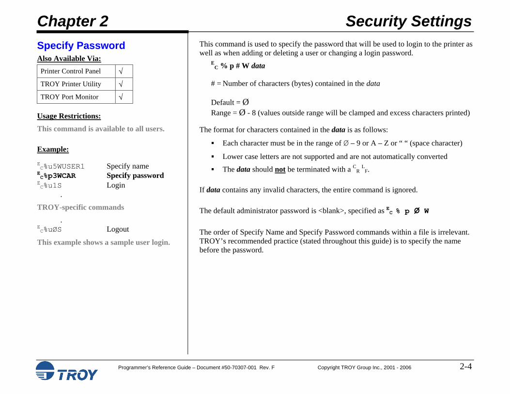
Specify Password Also Available Via: Printer Control Panel √
TROY Printer Utility √
TROY Port Monitor √
Usage Restrictions:
This command is available to all users.
Example:
EC%u5WUSER1 Specify name EC%p3WCAR Specify password EC%u1S Login .
TROY-specific commands . EC%uØS Logout
This example shows a sample user login.
This command is used to specify the password that will be used to login to the printer as well as when adding or deleting a user or changing a login password.
EC % p # W data
# = Number of characters (bytes) contained in the data Default = Ø Range = Ø - 8 (values outside range will be clamped and excess characters printed)
The format for characters contained in the data is as follows:
Each character must be in the range of Ø – 9 or A – Z or “ “ (space character)
Lower case letters are not supported and are not automatically converted
The data should not be terminated with a CR LF.
If data contains any invalid characters, the entire command is ignored.
The default administrator password is <blank>, specified as EC % p Ø W
The order of Specify Name and Specify Password commands within a file is irrelevant. TROY’s recommended practice (stated throughout this guide) is to specify the name before the password.
Chapter 2 Security Settings
Programmer’s Reference Guide – Document #50-70307-001 Rev. F Copyright TROY Group Inc., 2001 - 2006 2-5
Login and Logout Also Available Via: Printer Control Panel √
This example illustrates how to print an audit report. In order to print the report, which is considered secure information, a valid login must be provided. Note: In this example, a user login could have been provided instead of the administrator login.
This command uses the last specified name and password and logs user into the printer. E
C % u # S
# = Ø – Logout 1 – Login
Default = Ø Range = Ø - 1 (values outside range will be ignored if they are not other commands)
If an invalid name or password is specified, the login will fail and the printer will remain in its previous login security state.
The following is a partial list of printer features that require a valid login in order to use them.
Change the default settings for TROY Security Printing Solution configuration options.
Enter download mode (see below).
Add and delete secure resources stores on the secure file system.
Print TROY signatures, logos and other data stored in the secure file system.
Add, change or delete user names and passwords.
Print the user name and password list.
Configure, print and delete audit records.
Use TROY’s ExPT technology to adjust the image and MICR line on a page.
Re-map paper trays.
Configure the languages supported and decryption mode in use.
Print sample and maintenance documents containing MICR characters.
NOTE: If an end-of-job is observed in the print job data stream and no explicit logout commands is received, the printer will automatically log the current user off of the printer. As good programming practice, it is still recommended to logout at the end of each print job.
Chapter 2 Security Settings
Programmer’s Reference Guide – Document #50-70307-001 Rev. F Copyright TROY Group Inc., 2001 - 2006 2-6
Download Mode Also Available Via: Printer Control Panel
TROY Printer Utility √
TROY Port Monitor
Usage Restrictions:
You must be logged in as the administrator to place the printer into download mode.
Example:
EC%u5WADMIN Specify name EC%pØW Specify password EC%u1S Login EC%v1D Enter download EC%u5WUSER1 Specify name EC%p3WCAT Specify password EC%u2S Add user EC%vØD Exit download EC%uØS Logout
This example illustrates how to add a user login to a printer. Prior to adding the user, the printer must be placed into download mode, which requires a valid administrator login.
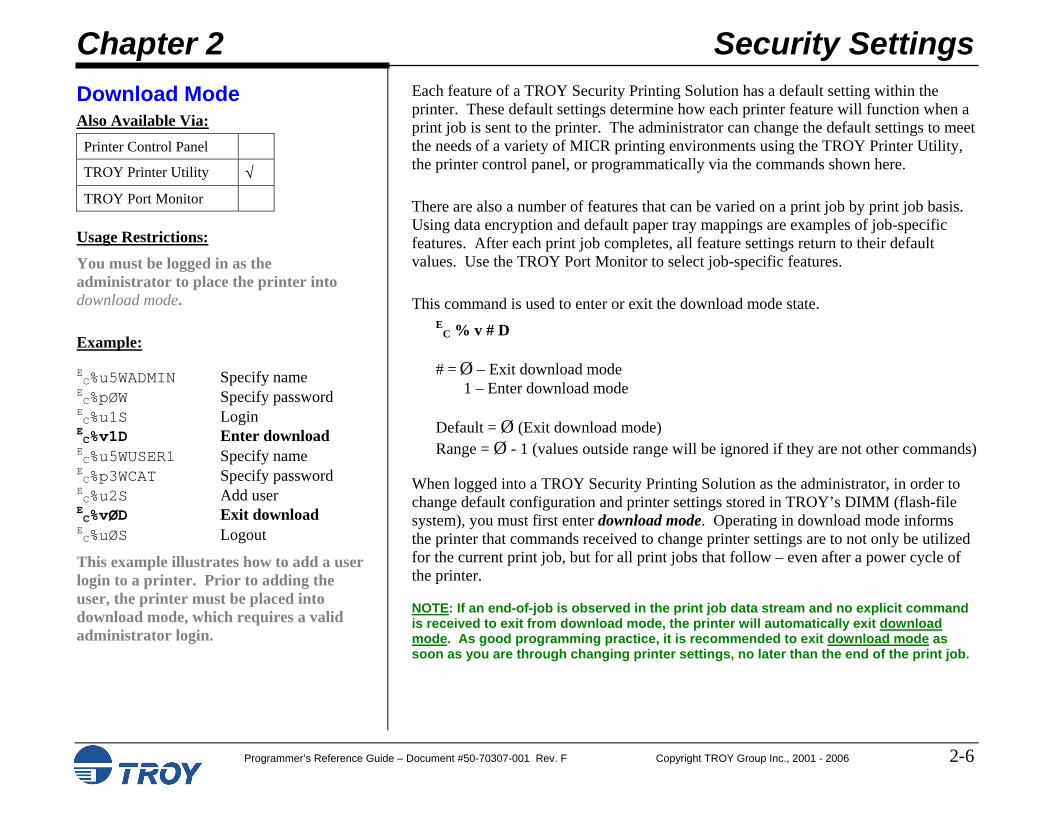
Each feature of a TROY Security Printing Solution has a default setting within the printer. These default settings determine how each printer feature will function when a print job is sent to the printer. The administrator can change the default settings to meet the needs of a variety of MICR printing environments using the TROY Printer Utility, the printer control panel, or programmatically via the commands shown here.
There are also a number of features that can be varied on a print job by print job basis. Using data encryption and default paper tray mappings are examples of job-specific features. After each print job completes, all feature settings return to their default values. Use the TROY Port Monitor to select job-specific features.
This command is used to enter or exit the download mode state. E
C % v # D # = Ø – Exit download mode
1 – Enter download mode Default = Ø (Exit download mode) Range = Ø - 1 (values outside range will be ignored if they are not other commands)
When logged into a TROY Security Printing Solution as the administrator, in order to change default configuration and printer settings stored in TROY’s DIMM (flash-file system), you must first enter download mode. Operating in download mode informs the printer that commands received to change printer settings are to not only be utilized for the current print job, but for all print jobs that follow – even after a power cycle of the printer.
NOTE: If an end-of-job is observed in the print job data stream and no explicit command is received to exit from download mode, the printer will automatically exit download mode. As good programming practice, it is recommended to exit download mode as soon as you are through changing printer settings, no later than the end of the print job.
Chapter 2 Security Settings
Programmer’s Reference Guide – Document #50-70307-001 Rev. F Copyright TROY Group Inc., 2001 - 2006 2-7
Printer Lock PIN Also Available Via: Printer Control Panel √
TROY Printer Utility √
TROY Port Monitor √
Usage Restrictions:
TROY MICR Secure and Secure EX only
You must place the printer into download mode before using the PIN Lock command.
Example:
EC%u5WADMIN Specify name EC%pØW Specify password EC%u1S Login EC%v1D Enter download EC%l4W1234 Set printer lock PIN EC%vØD Exit download EC%uØS Logout
In this example a Printer Lock PIN of “1234” is enabled. @PJL TROY PRINTER UNLOCK PIN=1234 C
R L
F
TROY Security Printing Solutions can be “locked” such that no print job will print until the user enters an administrator-specified PIN (Personal Identification Number) at the control panel of the printer. The Printer Lock PIN command is used to both enable and disable this feature as well as to specify the PIN number to be entered at the control panel to release jobs for printing. The command used to set the Printer Lock PIN is:
EC % l # W data
# = Number of characters (bytes) contained in the data
Default = Ø Range = Ø - 4 (values outside range will be clamped and excess characters printed)
The format for characters contained in the data is as follows:
Each character must be in the range of Ø – 9
A data (value) of Ø is the default and disables the Printer Lock PIN
Any data (value) between 1 and 9999 enables the Printer Lock PIN
The data should not be terminated with a CR LF.
When using a TROY MICR Secure EX printer containing a physical keylock, the physical keylock takes precedence over the Printer Lock PIN. Once the physical keylock is positioned to allow jobs to print, if the Printer Lock PIN is enabled, the user must enter the matching Printer Unlock PIN to release the job for printing.
It is also possible to unlock a Printer Lock PIN from within a print job. By including the following TROY PJL command with a matching Printer Unlock PIN in the PJL header of a print job, the Printer Lock PIN can be disabled just for the job containing the following command. This command can also be included in the Port Monitor’s PJL Include file as a means to automate delivery of the unlock command in Windows.
@PJL TROY PRINTER UNLOCK PIN=# CR
LF
# = Matching PIN number to the Printer Lock PIN
Chapter 2 Security Settings
Programmer’s Reference Guide – Document #50-70307-001 Rev. F Copyright TROY Group Inc., 2001 - 2006 2-8
MICR Lock PIN Also Available Via: Printer Control Panel √
TROY Printer Utility √
TROY Port Monitor
Usage Restrictions:
TROY MICR Secure and Secure EX only
You must place the printer into download mode before using the PIN Lock command.
Example:
EC%u5WADMIN Specify name EC%pØW Specify password EC%u1S Login EC%v1D Enter download EC%l1WØ Disable MICR lock
PIN EC%vØD Exit download EC%uØS Logout
In this example the MICR Lock PIN is disabled by setting the value to Ø. @PJL TROY MICR UNLOCK PIN=Ø C
R L
F
TROY Security Printing Solutions can be “locked” such that no MICR print job will print until the user enters an administrator-specified PIN number at the control panel of the printer. The MICR Lock PIN command is used to both enable and disable this feature as well as to specify the PIN number to be entered at the control panel to release MICR jobs for printing. The command used to set the MICR Lock PIN is as follows:
EC % m # W data
# = Number of characters (bytes) contained in the data Default = Ø Range = Ø - 4 (values outside range will be clamped and excess characters printed)
The format for characters contained in the data is as follows:
Each character must be in the range of Ø – 9
A data (value) of Ø is the default and disables the MICR Lock PIN
Any data (value) between 1 and 9999 enables the MICR Lock PIN
The data should not be terminated with a CR LF.
When using a TROY MICR Secure EX printer that has a physical keylock, the physical keylock takes precedence over the MICR Lock PIN. Once the physical keylock is positioned to allow MICR jobs to print, if the MICR Lock PIN is enabled, the user must enter the matching MICR Unlock PIN to release the MICR job for printing.
It is also possible to unlock a MICR Lock PIN from within a print job. By including the following TROY PJL command with a matching MICR Unlock PIN in the PJL header of a print job, the MICR Lock PIN can be disabled just for the job containing the following command. This command can also be included in the Port Monitor’s PJL Include file as a means to automate delivery of the unlock command in Windows.
@PJL TROY MICR UNLOCK PIN=# CR
LF
# = Matching PIN number to the MICR Lock PIN
Chapter 2 Security Settings
Programmer’s Reference Guide – Document #50-70307-001 Rev. F Copyright TROY Group Inc., 2001 - 2006 2-9
Job Name and PIN Also Available Via: Printer Control Panel
In this example the user would be prompted at the printer control panel to enter the Unlock PIN (5678) for the job named TEST1.
TROY Security Printing Solutions can also be “locked” on a job-by-job basis such that a specific print job will not print until the user enters a user-specified PIN number at the control panel of the printer. The Job Name and PIN command is used to both specify the job name to appear on the control panel identifying the job, as well as to specify the PIN number to be entered at the control panel to release a job for printing. The command used to set the Job Name and PIN is as follows:
@PJL TROY JOB NAME name PIN=# CR L
F name = A user-defined string to be displayed on the control panel, not to exceed 16 characters in length. # = The PIN number that must be entered at the control panel to release the job for printing. Default name = “” Default PIN Number = Ø (PIN disabled) PIN number range = Ø - 9999 (values outside range will be clamped)
When using a TROY MICR Secure EX printer that has a physical keylock, the physical keylock takes precedence over the Job Name and PIN command. Once the physical keylock is positioned to allow jobs to print, if the Job Name and PIN is enabled, the user must enter the matching Job Unlock PIN to release the job for printing.
NOTE: This command can also be included in the Port Monitor’s PJL Include file as a means to automate delivery of the Job Name and PIN lock command in Windows.
Chapter 2 Security Settings
Programmer’s Reference Guide – Document #50-70307-001 Rev. F Copyright TROY Group Inc., 2001 - 2006 2-10
Toner Sensor Response Also Available Via: Printer Control Panel √
TROY Printer Utility √
TROY Port Monitor
Usage Restrictions:
TROY MICR printers only
You must place the printer into download mode before using the Toner Sensor Response command.
Example:
EC%u5WADMIN Specify name EC%pØW Specify password EC%u1S Login EC%v1D Enter download EC%tØE Set to Halt EC%vØD Exit download EC%uØS Logout
In this example the Toner Sensor Response is set to Halt if TROY MICR toner is not sensed when a MICR print job has been received.
TROY Security Printers contain a toner sensor to detect when TROY MICR toner is installed in the printer. This security feature, in combination with the MICR mode command, MICR fonts, physical keylock and MICR Lock PIN, help to ensure all MICR documents are actually printed using MICR toner.
When a TROY Security Printer detects a MICR print job but does not detect that TROY MICR toner is installed in the printer, a security warning is displayed on the printer’s control panel informing the user to either install TROY MICR toner or cancel the print job. This response is called Halt and is the default security response to this situation.
It is sometimes desirable for a TROY Security Printer to respond differently when not detecting TROY MICR toner during MICR print jobs. The Toner Sensor Response command is used to set the response type.
EC % t # E
# = Toner Sensor Response type Default = Ø (Halt) Range = Ø - 3 (values outside range will be ignored)
The Toner Sensor Response options:
Ø – Halt: Prompt the user to install TROY MICR toner or cancel the job. The user cannot print the job without installing TROY MICR toner. {Default}
1 – Warn: Print the user to install TROY MICR toner. The user can either press the Go key (after which time the printer ignores the response from the toner sensor for the remainder of the job) or cancel the job.
2 – Ignore: The toner sensor is disabled and provides no security feedback.
3 – Flush: Automatically flushes any MICR print job received when the toner sensor does not sense TROY MICR toner.
Chapter 2 Security Settings
Programmer’s Reference Guide – Document #50-70307-001 Rev. F Copyright TROY Group Inc., 2001 - 2006 2-11
Add User Also Available Via: Printer Control Panel √
TROY Printer Utility √
TROY Port Monitor
Usage Restrictions:
TROY MICR Secure and Secure EX only
You must place the printer into download mode before using the Add User command.
Example:
EC%u5WADMIN Specify name EC%pØW Specify password EC%u1S Login EC%v1D Enter download EC%u5WUSER1 New user name EC%p3WCAT New user password EC%u2S Add user EC%vØD Exit download EC%uØS Logout
In this example a new user “USER1” with the password “CAT” was added to the printer.
This command is used to add a user name and password.
EC % u 2 S
Up to twenty user names and passwords can be configured to prevent unauthorized users from accessing the printer’s secure resources (digital images of signatures, logos, macros, MICR fonts, etc.) and other MICR features. Although the use of user names and passwords is not required to operate the TROY MICR Secure printers, TROY highly recommends using user names and passwords to increase peer-to-peer security, and to maintain a higher level of accountability of the users in your MICR printing network.
After logging in as the administrator, to add a user name and password to the printer, specify the new name and password using the same Specify Name and Specify Password commands as used for login, followed by the Add User command instead of the Login command. The printer will not automatically confirm the addition. However, by printing the user list either from the printer control panel, TROY Printer Utility, or programmatically via the Print User List command (see below), you can ensure the user name and password was successfully added.
NOTE: Duplicate names are not allowed. Attempts to add duplicate names are rejected by the printer and an error message appears on the control panel.
Chapter 2 Security Settings
Programmer’s Reference Guide – Document #50-70307-001 Rev. F Copyright TROY Group Inc., 2001 - 2006 2-12
Delete User Also Available Via: Printer Control Panel
TROY Printer Utility √
TROY Port Monitor
Usage Restrictions:
TROY MICR Secure EX printers only
You must put the printer in download mode before using the Delete User command.
Example:
EC%u5WADMIN Specify name EC%pØW Specify password EC%u1S Login EC%v1D Enter download EC%u5WUSER2 Name to delete EC %u3S Delete user EC%vØD Exit download EC%uØS Logout
In this example user “USER2” is deleted from the printer.
This command is used to delete a user name and password.
EC % u 3 S
After logging in as the administrator, to delete a user name and password to the printer, specify the user name to delete using the same Specify Name command as used for login, followed by the Delete User command instead of the Login command. The printer will not automatically confirm the deletion. However, by printing the user list either from the printer control panel, the TROY Printer Utility, or programmatically via the Print User List command (see below), you can ensure the user name and password was successfully deleted.
NOTE: You are never allowed to delete the ADMIN user name.
NOTE: If no matching user name is found, this command is ignored.
Chapter 2 Security Settings
Programmer’s Reference Guide – Document #50-70307-001 Rev. F Copyright TROY Group Inc., 2001 - 2006 2-13
Change Password Also Available Via: Printer Control Panel √
TROY Printer Utility √
TROY Port Monitor
Usage Restrictions:
You must place the printer into download mode before using the Change Password command.
Example:
EC%u5WADMIN Specify name EC%pØW Specify password EC%u1S Login EC%v1D Enter download EC%u5WUSER1 Specify name EC%p4WBIRD New password EC%u4S Change password EC%vØD Exit download EC%uØS Logout
In this example user “USER1”’s password was changed from “CAT” (in the example above) to “BIRD”.
This command is used to change a password.
EC % u 4 S
Since the administrator login cannot be deleted from the printer, use the change password command to create a secure password for the administrator. This command can also be used to change the password of any user login stored in the printer.
After logging in as the administrator, to change a password, specify the existing user name and new password using the same Specify Name and Specify Password commands as used for login, followed by the Change Password command instead of the Login command. The printer will not automatically confirm the password change. However, by printing the user list either from the printer control panel, the Printer Utility, or programmatically via the Print User List command (see below), you can ensure the password was successfully changed.
NOTE: If no matching user name is found, no change takes place.
Chapter 2 Security Settings
Programmer’s Reference Guide – Document #50-70307-001 Rev. F Copyright TROY Group Inc., 2001 - 2006 2-14
Delete All Users Also Available Via: Printer Control Panel √
TROY Printer Utility √
TROY Port Monitor
Usage Restrictions:
TROY MICR Secure EX printers only
You must place the printer into download mode before using the Delete All Users command.
Example:
EC%u5WADMIN Specify name EC%pØW Specify password EC%u1S Login EC%v1D Enter download EC%u5S Delete all users EC%vØD Exit download EC%uØS Logout
This command is used to delete all users names and passwords.
EC % u 5 S
After logging in as the administrator, to delete all user names and passwords in the printer (excluding the ADMIN administrator name and password), simply execute the delete all users command. The printer will not automatically confirm the removal of all users. However, by printing the user list either from the printer control panel, the Printer Utility, or programmatically via the Print User List command (see below), you can ensure that all names and passwords were successfully deleted.
NOTE: You are never allowed to delete the ADMIN user name and password.
Chapter 2 Security Settings
Programmer’s Reference Guide – Document #50-70307-001 Rev. F Copyright TROY Group Inc., 2001 - 2006 2-15
Print User List Also Available Via: Printer Control Panel √
TROY Printer Utility √
TROY Port Monitor
Usage Restrictions:
TROY MICR Secure EX printers only
You must be logged in as the administrator to use the Print User List command.
Example:
EC%u5WADMIN Specify name EC%pØW Specify password EC%u1S Login EC%u-1S Print user list EC%uØS Logout
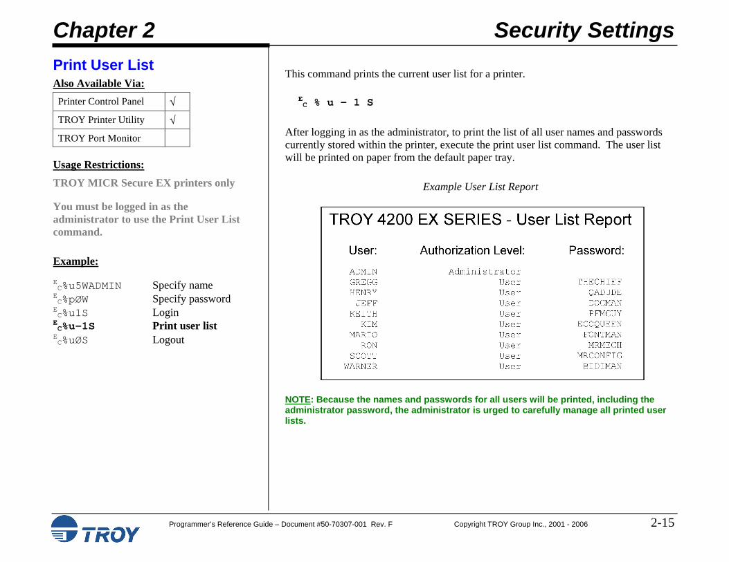
This command prints the current user list for a printer.
EC % u - 1 S
After logging in as the administrator, to print the list of all user names and passwords currently stored within the printer, execute the print user list command. The user list will be printed on paper from the default paper tray.
Example User List Report
NOTE: Because the names and passwords for all users will be printed, including the administrator password, the administrator is urged to carefully manage all printed user lists.
Chapter 3 Printing Control
Programmer’s Reference Guide – Document #50-70307-001 Rev. F Copyright TROY Group Inc., 2001 – 2006 3-1
MICR Mode Also Available Via: Printer Control Panel
TROY Printer Utility
TROY Port Monitor √
Usage Restrictions:
Can be set using the TROY Port Monitor. A valid user login is required to change the MICR mode.
Example:
EC%u5WADMIN Specify name EC%pØW Specify password E
C%u1S Login E
C%-124ØØX Enter MICR mode E
C%uØS Logout
This command is used to change the state of the MICR Mode of a TROY Security Printing Solution.
EC % - # X
# = 124ØØ – Enable (enter) 124Ø1 – Disable (exit)
Default = N/A Range = 124ØØ – 124Ø1 (values outside range may apply to other printer commands)
When using a TROY MICR Series printer, the following functions are performed at the beginning of each print job:
Disable automatic jam recovery
Set the printer’s print density to the optimum value for MICR printing
Enable low toner sensing and notification
When MICR mode is enabled, the following additional functions are performed:
Check the state of the MICR toner sensor. If TROY MICR toner is not installed the printer will respond per the Toner Sensor Response command noted later in this chapter.
Check the state of the keylock (Secure printers only). If the keylock is not in the Print MICR position, the printer will prompt the user to change the position to Print MICR.
Verify the job contains a valid user or administrator login. If the job does not contain a valid login, the job is aborted.
While MICR Mode is enabled, any font call to a TROY MICR font will cause the toner sensor, keylock, and login tests to be re-validated. If MICR mode is disabled and TROY fonts are requested within the print job, the Courier font will be substituted in place of the TROY MICR font to maintain the security of the printer.
Chapter 3 Printing Control
Programmer’s Reference Guide – Document #50-70307-001 Rev. F Copyright TROY Group Inc., 2001 – 2006 3-2
MICR Mode (cont.) When the state of the MICR Mode is changed within the context of a print job, it will return to its previous state when the print job completes or is cancelled. When changed outside of a job (via the printer control panel, for example), the state will persist until changed at a later time. MICR Modes do not persist through a power cycle of the printer. The MICR Mode will be affected by the Printer Type setting (see page 3-5).
Chapter 3 Printing Control
Programmer’s Reference Guide – Document #50-70307-001 Rev. F Copyright TROY Group Inc., 2001 – 2006 3-3
Print Quality Document Also Available Via: Printer Control Panel √
TROY Printer Utility √
TROY Port Monitor
Usage Restrictions:
Since the quality document contains MICR characters, a valid user login is required to print this document.
Example:
EC%-12345X HP PJL UEL @PJL JOB NAME="Sample" CR
LF
@PJL SET RESOLUTION=6ØØ CR L
F @PJL ENTER LANGUAGE="PCL"C
RL
F ECE PCL Reset EC&u6ØØD Set printer and PCL EC*t6ØØR resolution to 6ØØ dpi EC&lØO Set page orientation EC&l7H Set paper tray EC%u5WUSER1 Specify name EC%p3WCAT Specify password E
C%u1S Login EC%-124Ø3X Print Quality Doc. E
C%uØS Logout EC%-12345X HP PJL UEL @PJL EOJ NAME="Sample" CR
LF
EC%-12345X HP PJL UEL
This command is used to print the internal MICR quality document. The quality document is useful for diagnosing MICR print quality problems.
EC % - 1 2 4 Ø 3 X See the TROY Security Printing Solutions User’s Guide and the TROY Quick-Start Guide for usage instructions.
Chapter 3 Printing Control
Programmer’s Reference Guide – Document #50-70307-001 Rev. F Copyright TROY Group Inc., 2001 – 2006 3-4
Print Configuration Page Also Available Via: Printer Control Panel √
TROY Printer Utility √
TROY Port Monitor
Usage Restrictions:
This command is available to all users.
Example:
EC%-12345X HP PJL UEL @PJL JOB NAME="Sample" CR
LF
@PJL SET RESOLUTION=6ØØ CR L
F @PJL ENTER LANGUAGE="PCL"C
RL
F ECE PCL Reset EC&u6ØØD Set printer and PCL EC*t6ØØR resolution to 6ØØ dpi EC&lØO Set page orientation EC&l7H Set paper tray EC%-1242ØX Print Config. Page EC%-12345X HP PJL UEL @PJL EOJ NAME="Sample" CR
LF
EC%-12345X HP PJL UEL
This command is used to print the internal TROY Security Printing Solution configuration page. The configuration page contains the state of all TROY custom settings and modes.
EC % - 1 2 4 2 Ø X See the TROY Security Printing Solutions User Guide and the Quick Start Guide for usage instructions.
Chapter 3 Printing Control
Programmer’s Reference Guide – Document #50-70307-001 Rev. F Copyright TROY Group Inc., 2001 – 2006 3-5
Printer Type Also Available Via: Printer Control Panel √
TROY Printer Utility √
TROY Port Monitor
Usage Restrictions:
You must put the printer in download mode before using the Printer Type command.
Example:
EC%u5WADMIN Specify name EC%pØW Specify password EC%u1S Login EC%v1D Enter download EC%t2X MICR on EC%vØD Exit download EC%uØS Logout
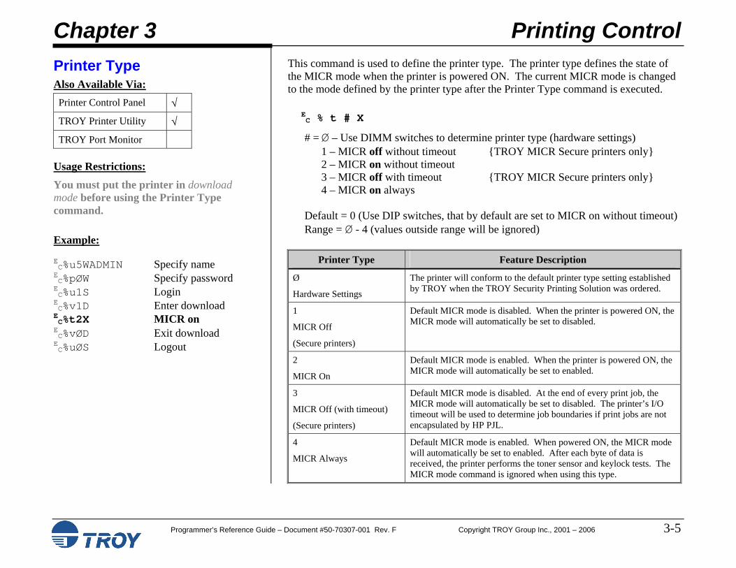
This command is used to define the printer type. The printer type defines the state of the MICR mode when the printer is powered ON. The current MICR mode is changed to the mode defined by the printer type after the Printer Type command is executed.
EC % t # X # = Ø – Use DIMM switches to determine printer type (hardware settings)
1 – MICR off without timeout {TROY MICR Secure printers only} 2 – MICR on without timeout 3 – MICR off with timeout {TROY MICR Secure printers only} 4 – MICR on always
Default = 0 (Use DIP switches, that by default are set to MICR on without timeout) Range = Ø - 4 (values outside range will be ignored)
Printer Type Feature Description
Ø
Hardware Settings
The printer will conform to the default printer type setting established by TROY when the TROY Security Printing Solution was ordered.
1
MICR Off
(Secure printers)
Default MICR mode is disabled. When the printer is powered ON, the MICR mode will automatically be set to disabled.
2
MICR On
Default MICR mode is enabled. When the printer is powered ON, the MICR mode will automatically be set to enabled.
3
MICR Off (with timeout)
(Secure printers)
Default MICR mode is disabled. At the end of every print job, the MICR mode will automatically be set to disabled. The printer’s I/O timeout will be used to determine job boundaries if print jobs are not encapsulated by HP PJL.
4
MICR Always
Default MICR mode is enabled. When powered ON, the MICR mode will automatically be set to enabled. After each byte of data is received, the printer performs the toner sensor and keylock tests. The MICR mode command is ignored when using this type.
Chapter 3 Printing Control
Programmer’s Reference Guide – Document #50-70307-001 Rev. F Copyright TROY Group Inc., 2001 – 2006 3-6
Remap Paper Trays Also Available Via: Printer Control Panel √
TROY Printer Utility √
TROY Port Monitor √
Usage Restrictions:
Can be set using the TROY Port Monitor. A valid user login is required to change the paper tray mapping state.
This command is used to control the state of the printer’s paper tray mapping feature. E
C % i # T # = Ø – Disable
1 – Enable Default = 1 (Enable) Range = Ø - 1 (values outside range will be ignored)
TROY Security Printing Solutions can be configured to use an alternate paper tray mapping sequence. Changing the paper tray mapping sequence may be necessary to adapt newer printers to older application data streams in which the PCL calls to select specific trays were different than they are with contemporary HP LaserJet Printers. This feature also provides an additional security mechanism by allowing the administrator to redirect PCL check paper tray selection commands to non-check paper trays. In this case, only authorized users with the proper user password can disable this re-mapping feature and use the default paper tray calls (thereby granting access to the check paper trays).
When enabled, the printer will map the paper tray calls to the values specified in the Specify Paper Tray Map command (see below). When disabled, the printer uses the default paper tray map (as shipped from the factory).
Chapter 3 Printing Control
Programmer’s Reference Guide – Document #50-70307-001 Rev. F Copyright TROY Group Inc., 2001 – 2006 3-7
Specify Paper Tray Map Also Available Via: Printer Control Panel
TROY Printer Utility √
TROY Port Monitor
Usage Restrictions:
You must put the printer in download mode before defining an alternate paper tray map.
Example:
EC%u5WADMIN Specify name EC%pØW Specify password EC%u1S Login EC%v1D Enter download EC%i3WØxØ5 ØxØ2 ØxØ1 EC%vØD Exit download EC%uØS Logout
In this example, only three PCL paper tray calls were being mapped. PCL paper tray call Ø1 (usually Tray 1) is being mapped to PCL tray call Ø5 (Tray 3). The PCL call for PCL paper tray Ø2 (Rear manual Feed paper) is mapped to itself (no change). PCL paper tray 3 (usually Manual Feed Envelop) is being mapped to PCL tray call Ø1 (Tray 1).
This command is used to define an alternate paper tray mapping. Only one alternate map per printer is supported.
EC % i # W data
# = Number of PCL tray calls being mapped (number of bytes of data) Default = Ø Range = Ø - 75 (values outside range will be ignored)
The format for data is as follows:
One hexadecimal number (byte) for each logical PCL tray call.
The data bytes received are considered in order. The first byte is the mapping for PCL Tray call #1, the second for PCL Tray call #2, and so on.
To map any given tray, all trays before the tray to remap must be included in the mapping command. Any tray that is not to be mapped, but that must be included in the command, should be mapped to itself (e.g. 1 – 1, 2 – 2, etc.).
The typical default PCL tray mappings for all TROY Security Printing Solutions include the following:
1 – Tray 1 {manual feed, general} 2 – Rear manual feed, paper 3 – Manual feed, envelop 4 – Tray 2 {top sheet feeder tray} 5 – Tray 3 {optional tray on TROY MICR ‘T’ Series printers} 6 – Envelop feeder {not applicable} 7 – Auto select 8 – Tray 4 {41ØØ, 42ØØ and 43ØØ only} 2Ø – High capacity tray {815Ø and 9ØØØ only} 21 – High capacity tray {815Ø and 9ØØØ only} 22 to 75 – External trays
Chapter 3 Printing Control
Programmer’s Reference Guide – Document #50-70307-001 Rev. F Copyright TROY Group Inc., 2001 – 2006 3-8
Alternate Escape Character Also Available Via: Printer Control Panel √
TROY Printer Utility √
TROY Port Monitor √
Usage Restrictions:
You must place the printer into download mode before defining an alternate escape character.
In this example, character Øx80 (128 decimal) has been defined as the alternate escape character. EC%-1242ØX Print config. Page
Once an alternate escape character is defined, it can be used in place of the normal escape command as shown above.
This command is used to define a character that can function exactly like an escape character (decimal 27, hexadecimal Øx1B). This feature is not normally required when printing from contemporary applications and environments (Windows 95 and newer).
EC % e # W data
# = Number of characters in the alternate escape-character sequence Default = 1 (only one character is supported in TROY Security Printing Solutions) Range = Ø - 1 (values outside range are ignored – they are reserved for future use)
Bytes in data will be in hexadecimal form.
Some environments (mainframe and mini-computer, for example) cannot output an escape character to a printer except via the printer driver. This makes it difficult for programmers to select and utilize many of the TROY security features.
This command allows a programmer to define an alternate character to be interpreted by the printer as the escape character (Øx1B). Whenever the printer sees the alternate character, it treats it as if it were an (Øx1B). TROY strongly recommends using characters above Øx7F for the alternate escape character because these characters are not commonly found in non-binary data streams.
This feature is designed to support only legacy systems and environments in which there are no other means for injecting the Øx1B character into the print job. Please contact TROY technical support should you require assistance in determining if and when to use this feature. Normally, this feature is not needed.
Chapter 3 Printing Control
Programmer’s Reference Guide – Document #50-70307-001 Rev. F Copyright TROY Group Inc., 2001 – 2006 3-9
Alternate Command Set Also Available Via: Printer Control Panel √
TROY Printer Utility √
TROY Port Monitor
Usage Restrictions:
(Optional to TROY Secure printers and DIMMs)
You must place the printer into download mode before sending the Alternate Command Set command to the printer.
Example:
EC%u5WADMIN Specify name EC%pØW Specify password EC%u1S Login EC%v1D Enter download EC%i1E Enable Alt. Cmd Set EC%vØD Exit download EC%uØS Logout
Some host applications are programmed to control MICR printers using what is sometimes referred to as the “%&” command set. This set of commands historically came from commands developed to control IBM printers. Today some Lexmark printers are also configured to support this legacy command set.
The optional Alternate Command Set feature translates “%&” commands into PCL 5e commands for processing in TROY Secure printers and DIMMs, providing easier application integration in some legacy MICR printing environments.
NOTE: Please contact your TROY Security Printing Solution reseller or TROY Group Inc. to see if this feature is applicable to your MICR printing environment.
The following command is used to enable translation of “%&” commands into PCL 5e commands.
# = Ø – Disable 1 – Enable
Default = Ø (Disabled) Range = Ø - 1 (values outside range will be ignored)
NOTE: Please contact your TROY Security Printing Solution reseller or TROY Group Inc. for a complete list of “%&” commands that can be translated into PCL 5e commands.
Chapter 3 Printing Control
Programmer’s Reference Guide – Document #50-70307-001 Rev. F Copyright TROY Group Inc., 2001 – 2006 3-10
TROY ExPT Image Control Also Available Via: Printer Control Panel √
TROY Printer Utility √
TROY Port Monitor
Usage Restrictions:
You must place the printer into download mode before using the ExPT Image Control commands.
These commands are used to fine-tune the location of the whole image as printed on the page.
EC % o # I {Image offset X – horizontal} EC % o # J {Image offset Y – vertical} # = Number of 1/72Ø of an inch to offset the image on the page. (+) moves image to the right and down, (-) moves the image to the left and up. Default = Ø Range = -72Ø to +72Ø (values outside range will be clamped)
The ANSI X/9B specifications for the placement of the MICR line relative to the bottom and right edges of a check document are tightly controlled in order to provide accurate reading by large, high speed banking system check readers. Electronic check forms are defined typically for one specific printer. For example, a TROY MICR 42ØØ Secure EX may be used to print a series of check that are later printed on other TROY MICR 42ØØ Secure EX printers or printers from other families or manufacturers. The paper feeding accuracy and image placement of each printer (even with the same family of printers from the same manufacturer) can vary to a sufficient degree to print the MICR line out of tolerance to the ANSI X/9B specification, resulting in rejected checks by the banking system check readers.
These commands allow the administrator of the printer to micro-adjust the positioning of the entire image on the printed page, thereby adjusting the MICR line. In the example shown here, the blue lines show the image moved ½” right and ¼” down.
Chapter 3 Printing Control
Programmer’s Reference Guide – Document #50-70307-001 Rev. F Copyright TROY Group Inc., 2001 – 2006 3-11
TROY ExPT MICR Line Control Also Available Via: Printer Control Panel √
TROY Printer Utility √
TROY Port Monitor
Usage Restrictions:
You must place the printer into download mode before using the ExPT MICR Line Control commands.
Example:
EC%u5WADMIN Specify name EC%pØW Specify password EC%u1S Login EC%v1D Enter download EC%o36ØM MICR line + ½” EC%o18ØN MICR line + ¼” EC%vØD Exit download EC%uØS Logout
These commands are used to fine-tune the location of the MICR as printed on the page. EC % o # M {MICR line offset X – horizontal} EC % o # N {MICR line offset Y – vertical} # = Number of 1/72Ø of an inch to offset the MICR line on the page. (+) moves MICR line to the right and down, (-) moves MICR line to the left and up. Default = Ø Range = -72Ø to +72Ø (values outside range will be clamped)
These commands allow the administrator of the printer to micro-adjust the positioning of the MICR line on the printed page without moving the remainder of the image. In the example shown below, the blue lines show the MICR line moving ½” right and ¼” down, while the rest of the image remains in place (black lines).
NOTE: Both image and MICR line offsets can be used at the same time. When used in combination, the MICR line is offset relative to the image offset.
NOTE: If the auto-rotate feature (described on the next page) is used in conjunction with the ExPT Offsets feature, any adjustments made with the ExPT Offsets feature to the left or top offset registration will have the same effect on the page regardless of the page orientation.
Chapter 3 Printing Control
Programmer’s Reference Guide – Document #50-70307-001 Rev. F Copyright TROY Group Inc., 2001 – 2006 3-12
Automatic Image Rotation Also Available Via: Printer Control Panel √
TROY Printer Utility √
TROY Port Monitor
Usage Restrictions:
You must place the printer into download mode before using the Automatic Image Rotation command.
Example:
EC%u5WADMIN Specify name EC%pØW Specify password EC%u1S Login EC%v1D Enter download EC%o1R Enable image rotate EC%vØD Exit download EC%uØS Logout
MICR reader/sorters use the lower right-hand corner of checks and other MICR documents as their anchors for determining MICR line positioning. Laser printers align image information to the upper left corner of a piece of paper. If the check paper is not consistently cut in lengths and widths that match how a check printing application applies image data on a laser printer, the MICR line can appear mal-positioned to a MICR reader/sorter. This can result in bank rejects, costing consumers money and banks time. This problem is most noticeable when MICR lines are printed at the bottom of a page, which is the most common form of payroll and payable check format.
TROY’s Security Printing Solutions feature Exact Positioning Technology (ExPT) that compensates for consistent MICR line and image placement errors usually resulting from application software that was written to print checks on pre-printed check stock that has been replaced by laser-printed documents. Variations in paper lengths and widths within reams or lots of paper can be compensated for using ExPT; however, the constant paper measurement process may become challenging for customers to manage.
The auto page rotation feature is designed to automatically rotate each page by 180 degrees, therefore, printing the MICR line at the very top of the paper where its positioning can be more accurately controlled. The auto-rotate feature does not operate unless the job has the PCL logical page orientation command embedded in the job.
The following command is used to enable or disable the Automatic Image Rotation feature.
EC % o # R
# = Ø – Disable 1 – Enable
Default = Ø (Disabled) Range = Ø - 1 (values outside range will be ignored)
NOTE: Only enable the Automatic Image Rotation feature when printing portrait MICR documents in which the MICR line is at the bottom of the paper. If the automatic page rotation feature is used in conjunction with the ExPT Offsets feature, then the image and MICR offsets must be adjusted accordingly (see note on previous page).
Chapter 3 Printing Control
Programmer’s Reference Guide – Document #50-70307-001 Rev. F Copyright TROY Group Inc., 2001 – 2006 3-13
Languages Supported Also Available Via: Printer Control Panel √
TROY Printer Utility √
TROY Port Monitor
Usage Restrictions:
You must place the printer into download mode before changing the supported printer languages.
Example:
EC%u5WADMIN Specify name EC%pØW Specify password EC%u1S Login EC%v1D Enter download EC%l1T Allow PCL 5 only EC%vØD Exit download EC%uØS Logout
The Languages Supported command provides a means to prevent jobs, formatted in printer languages such as Postscript and PCL-XL (a.k.a. PCL 6), from printing on a TROY Security Printing Solution. Restricting the languages supported to just PCL 5 increases the security of a TROY Security Printing Solution by reducing the number of ways pages can be ejected from the printer, while increasing the control an administrator has over data printed.
EC % l # T
# = Ø – All
1 – PCL 5 Default = Ø (All) Range = Ø - 1 (values outside range will be ignored)
NOTE: When the Languages Supported feature is set to PCL 5, many LaserJet configuration and status pages will not print, and a “Job Purged” message will be displayed or printed. Hewlett Packard uses PCL-XL as the data format for many of its internal pages. Set the Languages Supported feature to All before printing the LaserJet’s configuration pages.
Chapter 4 Secure and Public Resources
Programmer’s Reference Guide – Document #50-70307-001 Rev. F Copyright TROY Group Inc., 2001 – 2006 4-1
Introduction Storing Secure and Public Resources
Each TROY Security Printing Solution contains a non-volatile file system that can be used to store public and, in TROY Secure printers and DIMMs/memory cards, secure printer resources. Digitized signatures, logos, macros, form overlays, and data files (e.g., Secure Seal template files), or other PCL resources can be stored in the file system to minimize download time and increase resource availability and security.
The TROY Secure printers and DIMMs/memory cards also provide file system space for auditing purposes. The available flash memory on the TROY DIMMs/memory cards is shared between resource and audit data storage.
The Administrator is responsible for identifying those resources that should be stored as secure resources and those that should be stored as public resources. TROY recommends the following types of printer resources be stored in secure vs. public storage:
Digital signatures
Payroll check forms and overlays
Tax-related forms and overlays such as W-2 statements
If you need to store secure resources but your printer does not support secure resource storage, please consider upgrading to a TROY Secure printer or DIMM/memory card.
If user names and passwords are configured, a user must login using a valid user name and password to obtain access to these secure resources. Public resources, such as commonly used company logos or forms, can be stored in the public memory area for access by all users without requiring valid user login.
NOTE: Resources stored in a TROY Security Printing Solution file system will remain resident even when the printer power is switched OFF and ON.
Chapter 4 Secure and Public Resources
Programmer’s Reference Guide – Document #50-70307-001 Rev. F Copyright TROY Group Inc., 2001 – 2006 4-2
Introduction (cont.)
Resources are divided by PCL into three categories – fonts, macros/forms, and data files. The most common type of data file stored in the TROY DIMM/Memory Card is the Secure Seal template file (template.dat). To remain consistent with the PCL commands used to manipulate fonts, macros, and data files, TROY Security Printing Solutions support storage, access and removal of fonts, macros, and data files separately. All image files should be stored as fonts; bitmaps are not supported.
PCL also provides the means for storing fonts temporarily and permanently. TROY has extended the meaning of temporary and permanent storage when a print job containing font, macro, or data storage commands also places the printer into download mode. While in download mode, requests to store fonts, macros, and data files in temporary memory will cause these particular resources to be stored in the file system as public resources. Requests to store fonts, macros, or data files in permanent memory will cause these particular resources to be stored in the file system as secure resources (requiring user login to access them).
Chapter 4 Secure and Public Resources
Programmer’s Reference Guide – Document #50-70307-001 Rev. F Copyright TROY Group Inc., 2001 – 2006 4-3
Add Public Font Also Available Via: Printer Control Panel
TROY Printer Utility √
TROY Port Monitor
Usage Restrictions:
You must place the printer in download mode to add public fonts.
Example:
EC%u5WADMIN Specify name EC%pØW Specify password EC%u1S Login EC%v1D Enter download EC*c1ØØØØD Font ID 1ØØØØ EC)s88W Font header 88 bytes of font header data EC*cE Character code EC(s1636W Character Defn. 1636 bytes of character definition data
Repeat Character Code / Character Definition pairs until the entire font is downloaded into the printer EC*c4F {Make font public} EC%vØD Exit download EC%uØS Logout
(Refer to the HP PCL 5 Technical Reference Manual, Chapter 9 – Font Management and Chapter 11 – Soft Font Creation, for more information on standard PCL 5 commands used below.)
These commands will add a public font into the TROY Security Printing Solution file system. The method for adding the font is the same as adding a soft font into the printer, except that the commands are wrapped within download mode commands.
EC % v 1 D Enter Download Mode Command EC * c # D Font ID Command # = Font ID number Recommended to be at least 1Ø,ØØØ to avoid conflicts with other printer resources – range Ø - 32767 EC ) s # W data Download Font Header Command # = Number of bytes of font header data being downloaded EC * c # E data Character Code Command # = The character code in decimal associated with the next character download EC ( s # W data Character Definition Command # = Number of bytes defining the character in the data block
Repeat Character Code / Character Definition pairs until the entire font is downloaded into the printer
EC * c 4 F Make Font Public EC % v Ø D Exit Download Mode Command
Chapter 4 Secure and Public Resources
Programmer’s Reference Guide – Document #50-70307-001 Rev. F Copyright TROY Group Inc., 2001 – 2006 4-4
Add Secure Font Also Available Via: Printer Control Panel
TROY Printer Utility √
TROY Port Monitor
Usage Restrictions:
TROY Secure printers, DIMMs, and memory cards only
You must place the printer in download mode to add secure fonts.
Example:
EC%u5WADMIN Specify name EC%pØW Specify password EC%u1S Login EC%v1D Enter download EC*c1ØØØØD Font ID 1ØØØØ EC)s88W Font header 88 bytes of font header data EC*cE Character code EC(s1636W Character Defn. 1636 bytes of character definition data
Repeat Character Code / Character Definition pairs until the entire font is downloaded into the printer EC*c5F Make font secure EC%vØD Exit download EC%uØS Logout
(Refer to the HP PCL 5 Technical Reference Manual, Chapter 9 – Font Management and Chapter 11 – Soft Font Creation, for more information on standard PCL 5 commands used below.)
These commands will add a secure font into the TROY Secure file system. The method for adding the font is the same as adding a soft font into the printer, except that the commands are wrapped within download mode commands.
EC % v 1 D Enter Download Mode Command EC * c # D Font ID Command # = Font ID number Recommended to be at least 1Ø,ØØØ to avoid conflicts with other printer resources – range Ø - 32767 EC ) s # W data Download Font Header Command # = Number of bytes of font header data being downloaded EC * c # E data Character Code Command # = The character code in decimal associated with the next character download EC ( s # W data Character Definition Command # = Number of bytes defining the character in the data block
Repeat Character Code / Character Definition pairs until the entire font is downloaded into the printer
EC * c 5 F Make Font Secure EC % v Ø D Exit Download Mode Command
Chapter 4 Secure and Public Resources
Programmer’s Reference Guide – Document #50-70307-001 Rev. F Copyright TROY Group Inc., 2001 – 2006 4-5
Add Public Macro Also Available Via: Printer Control Panel
TROY Printer Utility √
TROY Port Monitor
Usage Restrictions:
You must place the printer in download mode to add public macros.
Example:
EC%u5WADMIN Specify name EC%pØW Specify password EC%u1S Login EC%v1D Enter download EC&f15ØØØY Macro ID 15ØØØ EC&fØX Start macro defn. .
PCL commands within macro . EC&f1X Stop macro defn. EC&f9X Make macro public EC%vØD Exit download EC%uØS Logout
(Refer to the HP PCL 5 Technical Reference Manual, Chapter 12 - Macros, for more information on standard PCL 5 commands used below.)
These commands will add a public macro into the TROY Security Printing Solution file system. The method for adding the macro is the same as adding a soft macro into the printer, except that the commands are wrapped within download mode commands.
EC % v 1 D Enter Download Mode Command EC & f # Y Macro ID Command # = Macro ID number Recommended to be at least 15,ØØØ to avoid conflicts with other printer resources – range Ø - 32767 EC & f 0 X Start Macro Definition Command
PCL commands contained in the macro are inserted here EC & f 1 X Stop Macro Definition Command EC & f 9 X Make Macro Public EC % v Ø D Exit Download Mode Command
All standard PCL macro rules, such as nesting levels and macro ID conflict resolution, apply to TROY public macros. Additionally, macros cannot reference other macros stored within the TROY Security Printing Solution file system.
Chapter 4 Secure and Public Resources
Programmer’s Reference Guide – Document #50-70307-001 Rev. F Copyright TROY Group Inc., 2001 – 2006 4-6
Add Secure Macro Also Available Via: Printer Control Panel
TROY Printer Utility √
TROY Port Monitor
Usage Restrictions:
TROY Secure printers, DIMMs, and memory cards only
You must place the printer in download mode to add secure macros.
Example:
EC%u5WADMIN Specify name EC%pØW Specify password EC%u1S Login EC%v1D Enter download EC&f15ØØØY Macro ID 15ØØØ EC&fØX Start macro defn. .
PCL commands within macro . EC&f1X Stop macro defn. EC&f1ØX Make macro secure EC%vØD Exit download EC%uØS Logout
(Refer to the HP PCL 5 Technical Reference Manual, Chapter 12 - Macros, for more information on standard PCL 5 commands used below.)
These commands will add a secure macro into the TROY Security Printing Solution file system. The method for adding the macro is the same as adding a soft macro into the printer, except that the commands are wrapped within download mode commands.
EC % v 1 D Enter Download Mode Command EC & f # Y Macro ID Command # = Macro ID number Recommended to be at least 15,ØØØ to avoid conflicts with other printer resources – range Ø - 32767 EC & f 0 X Start Macro Definition Command
PCL commands contained in the macro are inserted here EC & f 1 X Stop Macro Definition Command EC & f 1 Ø X Make Macro Secure EC % v Ø D Exit Download Mode Command
All standard PCL macro rules, such as nesting levels and macro ID conflict resolution, apply to TROY public macros. Additionally, macros cannot reference other macros stored within the TROY Security Printing Solution file system.
Chapter 4 Secure and Public Resources
Programmer’s Reference Guide – Document #50-70307-001 Rev. F Copyright TROY Group Inc., 2001 – 2006 4-7
Add Public Data File Also Available Via: Printer Control Panel
TROY Printer Utility √
TROY Port Monitor
Usage Restrictions:
You must place the printer in download mode to add public data files.
Example PCL data to download template named “DDSignature.est”:
EC%u5WADMIN Specify ADMIN user EC%pØW Specify password E
C%u1S User Login E
C%v1D Download mode in E
C %v20I Specify data ID of 20 E
C %v69752W Start template {data} 69752 binary bytes E
C%v33D To public area E
C%v20I Specify data ID of 20 E
C%h23W Specify name <00><00><00><03> 8 binary bytes <00><01><00><00> DDSignature.est Then template name E
C%v0D Download mode out E
C %v2D NV Report E
C%uØS User Logout
The most common type of data file stored in the TROY DIMM/Memory Card is the Secure Seal template file (template.dat). The encoding seal template (.est file) is typically loaded into the non-volatile secure memory area of the TROY printer in the “data” area. However, for MICR printers, which do not contain a secure memory area, the encoding seal template must be loaded into the public memory area. In either case, it is easiest to use the TROY Printer Utility to perform this download. Refer to the PCL commands contained in this chapter. When downloading the template file, note the file name (also printed on the NV report), because you will use a corresponding name when configuring the seal to use that specific template file. Refer to Chapter 10 – Secure Seals for additional information on creating and implementing seals.
Secure Seals can be created both automatically on the end of page event as well as explicitly via a “##SEAL” command. The field data that is encoded into the seal can come explicitly from a “##SEAL” command when an explicit seal is printed, or it can come from default field values configured previously, or it can come from metadata-tagged data within the print job stream.
Three new TROY PCL commands have been added to support the configuration of the secure seal feature: an option setting command to set some general options, a command to set a company ID, and the “##SEAL” command. The ##SEAL command is used to specify the name of the seal template, the X and Y location of the seal (optional), and the various field values (payee name, account number, etc.) to be encoded into the seal.
Refer to Chapter 10 – Secure Seals for additional information on creating and implementing seals.
Chapter 4 Secure and Public Resources
Programmer’s Reference Guide – Document #50-70307-001 Rev. F Copyright TROY Group Inc., 2001 – 2006 4-8
Add Secure Data File Also Available Via: Printer Control Panel
TROY Printer Utility √
TROY Port Monitor Usage Restrictions:
TROY MICR/IRD Secure and Secure EX Printers only. The seal options can be set using the TROY Printer Utility.
Example PCL data to download template named “DDSignature.est”:
EC%u5WADMIN Specify ADMIN user EC%pØW Specify password E
C%u1S User Login E
C%v1D Download mode in E
C %v20I Specify data ID of 20 E
C %v69752W Start template {data} 69752 binary bytes E
C%v32D To secure area E
C%v20I Specify data ID ot 20 E
C%h23W Specify name <00><00><00><03> 8 binary bytes <00><01><00><00> DDSignature.est Then template name E
C%v0D Download mode out E
C %v2D NV Report E
C%uØS User Logout
The most common type of data file stored in the TROY DIMM/Memory Card is the Secure Seal template file (template.dat). The encoding seal template (.est file) is typically loaded into the non-volatile secure memory area of the TROY printer in the “data” area. However, for MICR printers, which do not contain a secure memory area, the encoding seal template must be loaded into the public memory area. In either case, it is easiest to use the TROY Printer Utility to perform this download. Refer to the PCL commands contained in this chapter. When downloading the template file, note the file name (also printed on the NV report), because you will use a corresponding name when configuring the seal to use that specific template file. Refer to Chapter 10 – Secure Seals for additional information on creating and implementing seals.
Unlike fonts and macros, a PCL command is provided to assign a name to each ID; the default name is the same as the file name. The following PCL commands are only valid when the printer is in download mode:
<esc>%v#I Specify data ID
<esc>%v#W Specify contents of data file for last ID provided (# is replaced with length of data following W)
<esc>%v31D Delete one data file for last ID provided
<esc>%v32D Change data file to secure for last ID provided
<esc>%v33D Change data file to non-secure for last ID provided
<esc>%v34D Download data into print stream for last ID provided
<esc>%h#W<00><00><00><03><00><01><00><00><name> Specify name of data file for last ID provided (# is replaced with length of data following W, which is 8 + length of the name data)
Chapter 4 Secure and Public Resources
Programmer’s Reference Guide – Document #50-70307-001 Rev. F Copyright TROY Group Inc., 2001 – 2006 4-9
Print Resources List Also Available Via: Printer Control Panel
TROY Printer Utility √
TROY Port Monitor
Usage Restrictions:
You must place the printer in download mode to print the resources list.
Example:
EC%-12345X HP PJL UEL @PJL JOB NAME="Sample" CR
LF
EC%u5WADMIN Specify name EC%pØW Specify password EC%u1S Login EC%v2D Print resource list EC%uØS Logout @PJL EOJ NAME="Sample" CR
LF
EC%-12345X HP PJL UEL
This command prints a list of all resources currently stored in the file system on the TROY Security Printing Solution.
EC % v 2 D
Resources are separated into font and macro sections on the resource list. Those items preceded by an asterisk (*) are secure resources.
Chapter 4 Secure and Public Resources
Programmer’s Reference Guide – Document #50-70307-001 Rev. F Copyright TROY Group Inc., 2001 – 2006 4-10
Delete Resources Commands Also Available Via: Printer Control Panel
TROY Printer Utility √
TROY Port Monitor
Usage Restrictions:
Deletion of secure resources is supported only on TROY Secure printers, DIMMs, and memory cards.
You must place the printer in download mode to delete public or secure printer resources.
Example:
EC%u5WADMIN Specify name EC%pØW Specify password EC%u1S Login EC%v9D Delete all resource EC%uØS Logout
These commands delete resources currently stored in the flash-file system on the TROY Security Printing Solution file system. The following PCL commands are only valid when the printer is in download mode:
EC % v # D # = 7 – Delete all public resources
8 – Delete all secure resources 9 – Delete all resources 1Ø – Delete all public fonts 11 – Delete all secure fonts 12 – Delete all fonts 13 – Delete all public macros 14 – Delete all secure macros 15 – Delete all macros 16 – Delete all non-secure data 17 – Delete all secure data 18 – Delete all data
Default = N/A Range = 7-18 (values outside range may apply to other printer commands)
Chapter 5 Data Capture Fonts
Programmer’s Reference Guide – Document #50-70307-001 Rev. F Copyright TROY Group Inc., 2001 – 2006 5-1
Data Capture Types Also Available Via: Printer Control Panel
TROY Printer Utility √
TROY Port Monitor
Usage Restrictions:
TROY Secure printers and DIMMs only
Example:
. Preceding PCL EC(19U Select symbol set Select font EC(s1p8.ØØvØsØb166Ø2T EC%m771T Record for both $250.ØØ Data to record EC(19U Select symbol set Select font EC(s1p8.ØØvØsØb256T . . Remaining PCL
In this example, the string “$25Ø.ØØ” is recorded for TROYmark™ and auditing to use within the printer as a convenience amount. It will be printed on the document in the font selected.
Print job data, used by the TROYmark™ and user-configurable auditing features, is captured (identified and temporarily stored in the printer) through font selection. By specifying a font and then selecting one or more data capture types, all subsequent printable characters in the print job (up to the next font declaration) will be available to the printer for use as determined by the data capture type selected.
Within each data capture type command, a field identifier specifies the meaning of the data, which is then used by the printer to properly store, sort, and report based upon the declared field type.
EC % m # T
# = Ø – Manually terminate data capture (in lieu of a new font call or selection) 1 – Reserved {record number} 2 – Reserved {MICR line} 3 – Convenience Amount 4 – Payee Name 5 – Check Date {the date printed on the check, not the date of printing} 6 – Reserved {user name} 7 – Custom 1 {user-definable field} 8 – Custom 2 {user-definable field} 9 – Custom 3 {user-definable field} 10-Account #
11–Bank # 12–Check # 13–Transaction #
The # is then summed with the following values to determine the application for the data. The value to indicate a Seal attribute (high byte of metadata tag) is 1024. As an example, the font call for bank # should be 1024+11=1035 decimal.
# + 256 – Record as audit data
# + 512 – Record as TROYmark data
# + 768 – Record as both TROYmark and audit data
Default = Ø (Terminate data capture) Range = Ø – 9, 256 – 265, 512-521, 768-777 (values outside range are ignored) Maximum length of any data string captured – 128 characters Maximum length of all data strings recorded for audit record storage – 128 bytes Custom 1, 2, and 3 are concatenated into the one Custom field on the audit report.
Chapter 5 Data Capture Fonts
Programmer’s Reference Guide – Document #50-70307-001 Rev. F Copyright TROY Group Inc., 2001 – 2006 5-2
Invisible Print Data Also Available Via: Printer Control Panel
TROY Printer Utility √
TROY Port Monitor
Usage Restrictions:
TROY Secure printers and DIMMs only
Example:
. Preceding PCL EC(19U Select symbol set Select font EC(s1p8.ØØvØsØb166Ø2T EC%m521T TROYmark data,
field Custom 3 EC%m1I Do not print Happy Holidays Data to record EC(19U Select symbol set EC(s1p8.ØØvØsØb256T Select font . . Remaining PCL
In this example, the string “Happy Holidays” will be printed in the TROYmark™ image, but will not appear anywhere else on the document.
Any printable data can selectively be excluded from printing on the final document using the invisible print data feature. Examples of when printing data on the final document may not be desirable include:
When a string is to be printed within a TROYmark™ image but not printed in any other form on the document.
When placing data into the audit record in the custom field without wanting it appearing on the document (such as an internal control number).
TROY’s Auto-Protect security font.
The following command controls whether printable data is printed at the current position and in the current font.
EC % m # I # = Ø – Visible {print at the current position and in the current font}
1 – Invisible {do not print}
Default = Ø (Visible) Range = Ø – 1 (values outside range are ignored)
The invisible print data command remains in effect until changed, or until another font is selected.
Chapter 6 Barcode Fonts
Programmer’s Reference Guide – Document #50-70307-001 Rev. F Copyright TROY Group Inc., 2001 – 2006 6-1
Introduction
TROY barcode fonts provide all the glyphs necessary to print correctly formatted and scanable barcodes. Barcode elements must be explicitly chosen from the available set of font characters. The TROY firmware does not compute checksum nor does it automatically insert start, stop, or guard characters. When a barcode has multiple character sets that must be used at different times within a barcode, the user must explicitly make that choice. The TROY firmware does not make those choices for you.
TROY barcodes are selected by sending a PCL5 font selection sequence in a PCL5 job. The different selection sequence for each font is presented in the table below, where the escape character is represented by “EC”. The “<Height>” insert shown prior to the “v” parameter in each escape sequence represents a placeholder to indicate that any number may be substituted in that position. After the selection sequence, the specific data to create the bar pattern should be sent. The bar pattern data is usually followed by a different selection sequence to terminate the barcode, although it is possible to use PCL placement commands to place multiple barcodes of the same type without terminating the font selection in between sending the data for each barcode.
Programmer’s Reference Guide – Document #50-70307-001 Rev. F Copyright TROY Group Inc., 2001 – 2006 6-2
Interleaved 2 of 5 Also Available Via: Printer Control Panel
TROY Printer Utility √
TROY Port Monitor
Usage Restrictions:
TROY MICR Secure EX printers only
Example:
EC(4YE
C(s1p26v0s0b24640T<85h>-CY<86h>
Note: <#> - Hexadecimal value
Interleaved 2 of 5 is a numeric barcode, encoding two numeric characters per barcode element. By necessity, the barcode encodes an even number of digits, which includes a start and a stop character. The start and stop characters are not included in the checksum calculation.
A modulo 10 checksum (see POSTNET for calculation) is optional. The construction of the barcode is shown in the following condensed table. It is best used in fixed length applications because an angled (partial) scan can produce a start or stop code, causing an incorrect scan. Shorter data can be padded with leading zeros.
Index TROY Character Set Value Count ASCII Decimal Hex Start 1 <85H> 133 85 00-14 ! " # $ % & ' ( ) * + , - . / 33-47 21-2F 15-24 0 1 2 3 4 5 6 7 8 9 48-57 30-39 25-31 : ; < = > ? @ 58-64 3A-40 32-44 A B C D E F G H I J K L M 65-77 41-4D 45-57 N O P Q R S T U V W X Y Z 77-90 4E-5A 58-60 [ \ ] 91-93 5B-5D 61-63 ^ _ ` 94-96 5E-60 64-76 a b c d e f g h i j k l m 97-109 61-6D 77-89 n o p q r s t u v w x y z 110-122 6E-7A 90-99
any
{ | } ~ <7Fh> 123-132 7B-84 Stop 1 <86h> 134 86
Chapter 6 Barcode Fonts
Programmer’s Reference Guide – Document #50-70307-001 Rev. F Copyright TROY Group Inc., 2001 – 2006 6-3
Interleaved 2 of 5 (cont.)
The following table shows some Interleaved 2 of 5 examples. In each example, a checksum is not used. The callout for this font should occur after the PCL5 selection sequence and should be followed by a PCL5 selection sequence for a different font. In the “ASCII Callout” column, because the start and stop characters do not have printable ASCII equivalents, they are represented by a hex value and are set off by angled brackets (e.g., the text “<85h>” represents the single start character).
Programmer’s Reference Guide – Document #50-70307-001 Rev. F Copyright TROY Group Inc., 2001 – 2006 6-4
Code 128 Also Available Via: Printer Control Panel
TROY Printer Utility √
TROY Port Monitor
Usage Restrictions:
TROY MICR Secure EX printers only
Example:
EC(0YE
C(s1p26v0s0b24700T<87h>AB<83h><20h>+<84h>dw<8Ah>
Note: <#> - Hexadecimal value
Code 128 is an alphanumeric barcode with three character sets (also called “code” sets). Because of its different character sets, there are special symbols used to switch from one character set to another within the barcode. There are also three corresponding start characters. Character set A provides symbols, numbers, upper case letters, and unprintable control characters from the full ASCII set. Character set B provides symbols, numbers, upper and lower case letters from the full ASCII set. Character set C is optimized for numbers and encodes two numbers for each barcode character. Any given data can be encoded into a barcode in multiple ways.
The code 128 character sets are indexed by a value from 0 to 106, referred to as the “character value” in the barcode specification. The comparable characters in the TROY font are offset by 32 positions so that most of them fall in the printable range of characters and therefore are easier to select. In other words, given a character with a character value of N (base 10), the comparable character in the TROY font can be calculated by adding 32d to N.
The code 128 barcode requires start and stop characters; however, the start and stop characters are not included in the checksum calculation. The mandatory checksum is the remainder after dividing the sum of the start character and a weighted sum of character values in the barcode by 103. The weights are the index position of that character, starting at one. The resulting checksum is used as the index value regardless of the current character set.
The table on page 1-12 in Chapter 1 shows the different character sets and location of characters in the TROY font. As an example, the table shows that if the currently selected character is in character set A, then selecting position 131 in the TROY font will select the bar pattern that indicates the change to character set C. Another example is that if currently selected character is in character set C, then selecting position 1 in the TROY font will select the bar pattern that indicates the two digit sequence “01”.
NOTE: ASCII characters beyond the decimal value of 127 are not printable characters and are not typically used within the Code 128 barcode.
Chapter 6 Barcode Fonts
Programmer’s Reference Guide – Document #50-70307-001 Rev. F Copyright TROY Group Inc., 2001 – 2006 6-5
Code 128 (cont.)
The following table shows some Code 128 callout examples. The callout should be made after the PCL5 selection sequence for this font and should be followed by a PCL5 selection sequence for a different font. Notice the first three examples show alternative barcodes for the same data. Checksum calculations for the example shown in the first row of table below are 103+33*1+34*2+99*3+0*4+11*5+100*6+68*7=1632; 1632 divided by 103 leaves a remainder of 87. Checksum calculations for the example shown in the last row of the table are 105+0*1+22*2=149; 149 divided by 103 leaves a remainder of 46. In the “ASCII Callout” column, because some characters do not have printable ASCII equivalents (characters with a decimal value greater than 127), they are represented by the hex value and are set off by angled brackets (e.g., the text “<85h>” represents the single start character).
Data sum
Character Sets Used
Hex Callout for
TROY Font
ASCII Callout for TROY Font
AB0011d 87 A C B 87 41 42 83 20 2B 84 64 77 8A
<87h>AB<83h><20h>+<84>dw<8Ah>
AB0011d 53 B 88 37 38 30 30 31 31 64 55 8A
<88h>780011dU<8Ah>
AB0011d 8 A B 87 37 84 42 30 30 31 31 64 28 8A
<87h>7<84h>B0011d(<8A>
0022 46 C 89 20 36 4E 8A <89h><20h>6N<8Ah>
Chapter 6 Barcode Fonts
Programmer’s Reference Guide – Document #50-70307-001 Rev. F Copyright TROY Group Inc., 2001 – 2006 6-6
Code 39 Also Available Via: Printer Control Panel
TROY Printer Utility √
TROY Port Monitor
Usage Restrictions:
TROY MICR Secure EX printers only
Example:
EC(0YE
C(s1p26v0s0b24670T*ABC123$*
The Code 39 barcode, also known as code 3 of 9, is an alphanumeric barcode. It has a start character, any number of data characters, an optional checksum, and a stop character, which is the same as the start character. The optional checksum is the remainder after dividing the sum of each character value in the barcode by 43. The start and stop characters are not included in the checksum calculation.
The table on page 1-16 in Chapter 1 shows the different character sets and location of characters in the TROY font. To simplify the table, character ranges are given when possible. Like Code 128, the specification lays out the characters in an order different than ASCII. Because it is easier to call out using ASCII, the TROY font is arranged to fall within this range. As an example, the table shows that the barcode that encodes any character is in the corresponding spot in the ASCII table. The character that encodes “0” is in position 48, the character that encodes “*” is in position 42, etc.
The table below shows some examples. The callout should occur after the PCL5 selection sequence for this font and should be followed by a PCL5 selection sequence for a different font. The first two examples use the optional modulo 43 checksum. Checksum calculations for the example shown in the first row of Table 7 are 10+11+12+1+2+3=39; 39 divided by 43 leaves a remainder of 39. Checksum calculations for the example shown in the second row of Table 7 are 10+11+0+0+1+1=23; 23 divided by 43 leaves a remainder of 23.
Data Calculated Checksum Hex Callout for TROY Font ASCII Callout for
Programmer’s Reference Guide – Document #50-70307-001 Rev. F Copyright TROY Group Inc., 2001 – 2006 6-7
POSTNET and Reverse POSTNET Also Available Via: Printer Control Panel
TROY Printer Utility √
TROY Port Monitor
Usage Restrictions:
TROY MICR Secure EX printers only
Example:
EC(15YE
C(s1p18v0s0b24770T[927804]
The POSTNET and Reverse POSTNET barcodes are specified similarly; the only difference is the glyphs for the Reverse POSTNET are reversed so that they can be printed from the back side of a page, creating a scanable image that is correctly oriented on the front of the page (envelope). This postal barcode is unlike other linear barcodes in that the data is encoded in the height of the bars. POSTNET barcodes are numeric and include start and stop characters and a checksum. POSTNET can be created with a different number of digits; the most common are five, nine, and eleven digits. The construction of the POSTNET barcode is shown on page 1-17 in Chapter 1.
For each barcode, the checksum is calculated as the smallest number that can be added to the sum of the digits so that the total sum would be a multiple of 10. For example, given data of “012345678”, the sum is 36 and hence the checksum is 4. The start and stop characters are not included in the checksum calculation.
The following table shows some examples applicable to either of the POSTNET fonts. The callout should occur after the PCL5 selection sequence for this font and should be followed by a PCL5 selection sequence for a different font.
Number Calculated Checksum Hex Callout for TROY Font ASCII Callout for TROY
Programmer’s Reference Guide – Document #50-70307-001 Rev. F Copyright TROY Group Inc., 2001 – 2006 6-8
EAN and UPC Barcodes
The EAN and UPC barcodes are very similar, all being numeric with guard bars, checksums, and similar bar encoding. In general, they encode one or more number system characters, a manufacturer code, a product number code, and a checksum.
Each of the different barcodes has multiple character sets. Those character sets can be termed right or left hand depending on whether the character is to be used on the left of any middle guard bars (or there are no middle guard bars) or to be used on the right of any middle guard bars. Those character sets can also be termed odd or even parity depending on whether the sum of the bar module widths in a given character is an even or odd number of units. Both EAN-13 and UPC-E use left character sets in both odd and even parity forms; the pattern of odd and even parity encode additional information not represented by an explicit barcode glyph. Only the second number system character has an explicit barcode glyph.
For each barcode, the checksum is calculated the same way. The digit in the right-most position (just prior to any checksum) is termed “odd” and the digit to its left is “even”. Digits are counted to the left alternating in this way between even and odd. The digit values for odd positions are summed and that sum is multiplied by 3 and then added to the sums of the even positions. The checksum is the number that is added to this value to make is an even multiple of 10. So if the weighted sum is 66, the checksum is 4. The start and stop characters are not included in the checksum calculation.
The similarities in construction of these four barcode symbologies are shown in the table on the page 1-19 in Chapter 1. In this table, the components of each of the different barcode types are presented row by row. The “Count” (Ct) column gives the number of this type of barcode pattern to be used. When the parity of the barcode pattern is used to encode additional information (as mentioned above), the count is an aggregate of the types. The right columns indicate the location in the corresponding TROY font required to create this character. Detailed use and examples are shown on the following pages.
Chapter 6 Barcode Fonts
Programmer’s Reference Guide – Document #50-70307-001 Rev. F Copyright TROY Group Inc., 2001 – 2006 6-9
EAN 13 Also Available Via: Printer Control Panel
TROY Printer Utility √
TROY Port Monitor
Usage Restrictions:
TROY MICR Secure EX printers only
Example:
EC(8YE
C(s1p26v0s0b24630Ta000001mBCDEFG]
EAN-13 barcode incorporates a manufacturer code obtained from the European Article Numbering (EAN) authority. A product code is also incorporated in the barcode and is determined by manufacturer. The first system digit is determined by the sequence of parity patterns for the left side digits.
Besides the left, right, and middle guard patterns in the EAN-13 barcode, there are two digits for the country code, 5 digits for the manufacturer ID, 5 digits of product ID, and 1 digit for the checksum. Therefore, an EAN-13 barcode requires the placement of the start guard bar pattern, then six instances of left side odd or even parity bar patterns, then the middle guard pattern, then six instances of right side even parity bar patterns, then finally the right guard bar pattern.
As just mentioned, only the second number system character has an explicit barcode glyph. The first system number is encoded in the pattern of odd/even parity of the left-most digits. There are five explicit digits after the system number and prior to the middle guard. Representing odd parity with “odd” and even parity with “even”, the following table shows when to use a left odd or left even parity pattern for each of those digits prior to the middle guard.
Manufacturers Digit First System
Digit
Second System Digit
Parity 1 2 3 4 5
0 Odd Odd Odd Odd Odd Odd 1 Odd Odd Even Odd Even Even 2 Odd Odd Even Even Odd Even 3 Odd Odd Even Even Even Odd 4 Odd Even Odd Odd Even Even 5 Odd Even Even Odd Odd Even 6 Odd Even Even Even Odd Odd 7 Odd Even Odd Even Odd Even 8 Odd Even Odd Even Even Odd 9 Odd Even Even Odd Even Odd
Chapter 6 Barcode Fonts
Programmer’s Reference Guide – Document #50-70307-001 Rev. F Copyright TROY Group Inc., 2001 – 2006 6-10
EAN 13 (cont.)
The following table shows some examples. The callout should occur after the PCL5 selection sequence for this font and should be followed by a PCL5 selection sequence for a different font. In the “Bar Parity Pattern for Left Digits” column, “Even” is abbreviated as “E” and “Odd” is abbreviated as “O”.
Programmer’s Reference Guide – Document #50-70307-001 Rev. F Copyright TROY Group Inc., 2001 – 2006 6-11
EAN 8 Also Available Via: Printer Control Panel
TROY Printer Utility √
TROY Port Monitor
Usage Restrictions:
TROY MICR Secure EX printers only
Example:
EC(8YE
C(s1p26v0s0b24620T[1112mDEFD]
The EAN-8 barcode has product code information assigned directly by the European Article Numbering (EAN) authority and hence does not incorporate a manufacturing code.
Besides the left, right, and middle guard patterns in the EAN-8 barcode, there are two-digits for the country code, 5 digits for the product ID, and 1 digit for the checksum. Therefore, an EAN-8 barcode requires the placement of the start guard bar pattern, then four instances of left side odd parity bar patterns, then the middle guard pattern, then four instances of right side even parity bar patterns, and then finally the right guard bar pattern.
The following table shows some examples. The callout should occur after the PCL5 selection sequence for this font and should be followed by a PCL5 selection sequence for a different font.
Programmer’s Reference Guide – Document #50-70307-001 Rev. F Copyright TROY Group Inc., 2001 – 2006 6-12
UPC-A Also Available Via: Printer Control Panel
TROY Printer Utility √
TROY Port Monitor
Usage Restrictions:
TROY MICR Secure EX printers only
Example:
EC(8YE
C(s1p<Height>v0s0b24600T[b00001mBCDEFq]
The UPC-A has an implied first system number character of 0. The table on page 6-9 shows all the left digits use the odd parity left character set. Like EAN-13, the left digits encode a manufacturer ID of up to 8 digits obtained from the European Article Numbering authority, and the right digits represent a product code assigned by the manufacturer.
The UPC-A barcode has a combined left guard and system number, 5 digits (can be extended up to 8 digits) for the manufacturer ID, 1 middle guard bar pattern, 5 digits for the product ID, and a combined checksum digit bar pattern and right guard. Therefore, a UPC-A barcode requires the placement of the combined start guard bar pattern and system number, then five instances of left side odd, then the middle guard pattern, then five instances of right side even parity bar patterns, and then finally the placement of the combined checksum bar pattern and right guard bar pattern.
The following table shows some examples. The callout should occur after the PCL5 selection sequence for this font and should be followed by a PCL5 selection sequence for a different font.
Programmer’s Reference Guide – Document #50-70307-001 Rev. F Copyright TROY Group Inc., 2001 – 2006 6-13
UPC-E Also Available Via: Printer Control Panel
TROY Printer Utility √
TROY Port Monitor
Usage Restrictions:
TROY MICR Secure EX printers only
Example:
EC(8YE
C(s1p26v0s0b24610Tb1C9J9Au
The UPC-E barcode is an abbreviated form of the UPC-A barcode using a zero-suppressing compression scheme. There are no middle guard bars. Only UPC-A barcodes with system number of 0 (zero) can be represented as a UPC-E barcode. The checksum is computed based on the equivalent UPC-A barcode.
There is no explicit checksum nor is there an explicit system number. The checksum and the system number are encoded in the pattern of odd/even parity of digits. Representing odd parity with “odd” and even parity with “even”, the following table shows when to use a left odd or left even character set for each of the digits in barcode.
Parity Encoding if System Number is 0 for each Digit Position
Checksum 1 2 3 4 5 6 0 Even Even Even Odd Odd Odd 1 Even Even Odd Even Odd Odd 2 Even Even Odd Odd Even Odd 3 Even Even Odd Odd Odd Even 4 Even Odd Even Even Odd Odd 5 Even Odd Odd Even Even Odd 6 Even Odd Odd Odd Even Even 7 Even Odd Even Odd Even Odd 8 Even Odd Even Odd Odd Even 9 Even Odd Odd Even Odd Even
The UPC-A barcode has a left guard and right guard, and six digits for the data. Therefore, a UPC-A barcode requires the placement of the combined visual system number and left guard, then six instances of left side odd or even parity bar patterns, and then the placement of the combined right guard and visual checksum digit.
Chapter 6 Barcode Fonts
Programmer’s Reference Guide – Document #50-70307-001 Rev. F Copyright TROY Group Inc., 2001 – 2006 6-14
UPC-E (cont.) The zero-suppressing compression scheme to convert UPC-A barcode to an equivalent UPC-E barcode only works in some cases and is summarized in the table below. Rules should be checked in order from 1 to 6. An example of a UPC-A barcode that will not convert to a UPC-E barcode would be if the Manufacturer ID was 12345 and the product ID was any number in range 00000-00004 or in the range 00010-99999. Notice that the last digit in the zero suppressed form indicates the rule used for compression and hence the ease that a UPC-E barcode can be converted back to full UPC-A data.
Rule Mfg. ID
to Encode
Product ID to
Encode
Zero Suppressed
Form Notes
1 MM000 00PPP MMPPP0 Mfg ID ends in 000. Prod ID is 00000 – 00999
2 MM100 00PPP MMPPP1 Mfg ID ends in 100. Prod ID is 00000 – 00999
3 MM200 00PPP MMPPP2 Mfg ID ends in 200. Prod ID is 00000 – 00999
4 MMM00 000PP MMMPP3 Mfg ID ends in 00. Prod ID is 00000 – 00099
5 MMMM0 0000P MMMMP4 Mfg ID ends in 0. Prod ID is 00000 – 00009
6 MMMMM 0000P MMMMMP Mfg ID does not end in 0. Prod. ID is 00005-00009
Chapter 6 Barcode Fonts
Programmer’s Reference Guide – Document #50-70307-001 Rev. F Copyright TROY Group Inc., 2001 – 2006 6-15
UPC-E (cont.)
The following table shows some examples. The callout should occur after the PCL5 selection sequence for this font and should be followed by a PCL5 selection sequence for a different font. In the “Bar Parity Pattern” column, “Even” is abbreviated as “E” and “Odd” is abbreviated as “O”. Use the system number to determine the Bar Parity Pattern, use the Manufacturer ID end range and Product ID range in Table 16 to suppress the zeros in the UPC-A font.
Programmer’s Reference Guide – Document #50-70307-001 Rev. F Copyright TROY Group Inc., 2001 – 2006 7-1
TROYmark™ Control Also Available Via: Printer Control Panel
TROY Printer Utility
TROY Port Monitor √
Usage Restrictions:
TROY MICR Secure EX printers only
A valid user login is required to use the TROYmark™ feature.
Example:
EC%u5WADMIN Specify name EC%pØW Specify password EC%u1S Login EC%w2M Enable, medium EC%wØB Clear region list EC%w1B Inclusion region EC%wØX Region anchor X EC%w42ØØY Region anchor Y EC%w48ØØH Region width EC%w18ØØV Region height EC%w2B Exclusion region EC%w395ØX Region anchor X EC%w45ØY Region anchor Y EC%w9ØØH Region width EC%w3ØØV Region height Remaining PCL data plus data capture E
C%uØS {Logout}
This command defines if the TROYmark™ feature is to be enabled, and if so, which pre-defined pattern will be used to print the TROYmark™ text.
EC % w # M # = Ø – Disable
1 – Enable and print using printer’s default light pattern 2 – Enable and print using printer’s default medium pattern 3 – Enable and print using printer’s default dark pattern 4 – Enable and print using printer’s Custom 1 pattern 5 – Enable and print using printer’s Custom 2 pattern 6 – Enable and print using printer’s Custom 3 pattern
Default = 2 (Enable, default medium pattern) Range = Ø - 6 (values outside range are ignored)
TROYmark™ configurations persist throughout the life of a print job, however, do not persist beyond the job and must be included in each job that desires to use this feature. Multiple TROYmark™ configurations can, however, be defined within one job should multiple document styles require multiple TROYmark™ configurations.
To see the default patterns available on your printer, print out the CONFIGURATION page using the TROY INFORMATION MENU.
Chapter 7 TROYmark Settings
Programmer’s Reference Guide – Document #50-70307-001 Rev. F Copyright TROY Group Inc., 2001 – 2006 7-2
TROYmark™ Regions Also Available Via: Printer Control Panel
TROY Printer Utility
TROY Port Monitor √
Usage Restrictions:
TROY MICR Secure EX printers only
A valid user login is required to use the TROYmark™ feature.
Example:
EC%u5WADMIN Specify name EC%pØW Specify password EC%u1S Login EC%w2M Enable, medium EC%wØB Clear region list EC%w1B Inclusion region EC%wØX Region anchor X EC%w42ØØY Region anchor Y EC%w48ØØH Region width EC%w18ØØV Region height EC%w2B Exclusion region EC%w395ØX Region anchor X EC%w45ØY Region anchor Y EC%w9ØØH Region width EC%w3ØØV Region height Remaining PCL data plus data capture EC%uØS Logout
This command determines the type of region that subsequent size commands will define.
EC % w # B # = Ø – Reset (clear) all regions
1 – Inclusion region 2 – Exclusion region
Default = Ø (Reset all regions) Range = Ø - 2 (values outside range are ignored)
TROYmark™ configurations persist throughout the life of a print job, however, do not persist beyond the job and must be included in each job that desires to use this feature. Multiple TROYmark™ configurations can, however, be defined within one job should multiple document styles require multiple TROYmark™ configurations.
At the beginning of any job setup to use TROYmark™, all regions should be cleared. This prevents lingering region definitions that may not have been cleared after abnormal job terminations from persisting into new jobs.
Only one inclusion region is allowed per printed page. Up to 10 exclusion regions are allowed per printed page. To conform to the ANSI X9/B standard for automated check processing, the convenience amount must not contain TROYmark™ images. Therefore, at a minimum, it must be excluded.
Chapter 7 TROYmark Settings
Programmer’s Reference Guide – Document #50-70307-001 Rev. F Copyright TROY Group Inc., 2001 – 2006 7-3
Region Sizes Also Available Via: Printer Control Panel
TROY Printer Utility
TROY Port Monitor √
Usage Restrictions:
TROY MICR Secure EX printers only.
A valid user login is required to use the TROYmark™ feature.
Example:
EC%u5WADMIN Specify name EC%pØW Specify password EC%u1S Login EC%w2M Enable, medium EC%wØB Clear region list EC%w1B Inclusion region EC%wØX Region anchor X EC%w42ØØY Region anchor Y EC%w48ØØH Region width EC%w18ØØV Region height EC%w2B Exclusion region EC%w395ØX Region anchor X EC%w45ØY Region anchor Y EC%w9ØØH Region width EC%w3ØØV Region height Remaining PCL data plus data capture EC%uØS Logout
The following four commands define the location and size of any TROYmark™ region.
EC % w # X {Upper left anchor corner of the region}
EC % w # Y {Upper left anchor corner of the region}
EC % w # H {Region width}
EC % w # V {Region height}
# = Distance in 1/600’s of an inch {e.g. 48ØØ / 6ØØ = 8”} Default = Ø Range = Ø – 10200 (17”) (values outside range are clamped)
TROYmark™ configurations persist throughout the life of a print job, however, do not persist beyond the job and must be included in each job that desires to use this feature. Multiple TROYmark™ configurations can, however, be defined within one job should multiple document styles require multiple TROYmark™ configurations.
When specifying the location of the inclusion region, the X and Y anchor corner values are measured from the upper left corner of the image on the printed page. The values are an absolute measure of distance from this point. The inclusion region must never be closer than ¼” from the MICR line.
When specifying the location of exclusion regions, the X and Y anchor corner values are measured from the upper left corner of the inclusion region. Therefore, these values are relative and will automatically adjust should the inclusion region location change.
Chapter 7 TROYmark Settings
Programmer’s Reference Guide – Document #50-70307-001 Rev. F Copyright TROY Group Inc., 2001 – 2006 7-4
Custom TROYmark™ Patterns Also Available Via: Printer Control Panel
TROY Printer Utility √
TROY Port Monitor
Usage Restrictions:
TROY MICR Secure EX printers only
You must put the printer in download mode to update the default TROYmark™ pattern values.
Example:
EC%u5WADMIN Specify name EC%pØW Specify password EC%u1S Login EC%v1D Enter download EC%w4P Select pattern 4 EC%w32W data Download pattern EC%vØD Exit download EC%uØS Logout
There are three custom patterns (gray levels) that can be defined for use in TROYmark™ imaging. Each pattern is a 16 x 16 matrix of binary ones and zeros.
To change a printer pattern, the pattern to be updated must first be selected.
EC % w # P # = 1 – Reserved {printer default light pattern}
Default = 4 (Custom 1) Range = 4 - 6 (values outside range are ignored)
The pattern data is then downloaded into the printer.
EC % w # W data # = Total number of bytes contained in the pattern Default = 32 Range = 32 (values outside range are ignored)
The format of the data is as follows:
1ØØØ1ØØØ1ØØØ1ØØØ {Row 1, sent as Øx88 Øx88} ØØ1ØØØØ1ØØØ1ØØ1Ø {Row 2, sent as Øx22 Øx22} …. ØØ1ØØØØ1ØØØ1ØØ1Ø {Row 16, sent as Øx22 Øx22}
All bytes are concatenated together with no delimiters between bytes. The most significant bit of the first byte sent is the upper left corner of the pattern.
Chapter 8 Audit Options
Programmer’s Reference Guide – Document #50-70307-001 Rev. F Copyright TROY Group Inc., 2001 – 2006 8-1
Sort By Also Available Via: Printer Control Panel √
TROY Printer Utility √
TROY Port Monitor
Usage Restrictions:
TROY Secure printers and DIMMs only
You must put the printer in download mode before using the Sort By command.
Example:
EC%u5WADMIN Specify name EC%pØW Specify password EC%u1S Login EC%v1D Enter download EC%a3S Select sort by field EC%vØD Exit download EC%uØS Logout
This command defines which data capture field will be used as the sort key during audit report printing.
EC % a # S # = 1 – Audit Record Number
2 – MICR Line 3 – Convenience Amount 4 – Payee Name 5 – Date 6 – User Name 7 – Custom (concatenation of Custom 1, Custom 2 and Custom 3)
Default = 1 (Audit Record Number) Range = 1 – 7 (values outside range are ignored)
The sort by value specified is used for all subsequent audit reports until changed.
The following table defines the type of sorting performed for each data capture field.
Field Sort Type
1 - Audit Record Number Numeric
2 – MICR Line Numeric
3 – Convenience Amount Numeric
4 – Payee Name Alphanumeric
5 – Date Numeric
6 – User Name Alphanumeric
7 - Custom Alphanumeric
Chapter 8 Audit Options
Programmer’s Reference Guide – Document #50-70307-001 Rev. F Copyright TROY Group Inc., 2001 – 2006 8-2
Audit Paper Tray Also Available Via: Printer Control Panel √
TROY Printer Utility √
TROY Port Monitor
Usage Restrictions:
TROY Secure printers and DIMMs only
You must place the printer into download mode before using the Audit Paper Tray command.
Example:
EC%u5WADMIN Specify name EC%pØW Specify password EC%u1S Login EC%v1D Enter download EC%a7T Auto select tray EC%vØD Exit download EC%uØS Logout
This command defines which paper tray will be used during audit report printing.
Default = 7 (default paper tray) Range = 1 – 75 (values outside range are ignored)
The audit paper tray value specified is used for all subsequent audit reports until changed.
NOTE: The tray numbers listed above reflect tray numbers for the 4050, 4100, 4200, 4300, 8000, 8100, and 8150 printer models. Please consult the HP User Guide located on the HP CD accompanying the printer for other printer tray numbers.
If paper tray mapping has been configured in the printer, the tray number specified by this command may be re-mapped by the tray-mapping configuration.
Chapter 8 Audit Options
Programmer’s Reference Guide – Document #50-70307-001 Rev. F Copyright TROY Group Inc., 2001 – 2006 8-3
Print Range Also Available Via: Printer Control Panel √
TROY Printer Utility √
TROY Port Monitor
Usage Restrictions:
TROY Secure printers and DIMMs only
You must put the printer in download mode before using the Print Range command.
Example:
EC%u5WADMIN Specify name EC%pØW Specify password EC%u1S Login EC%v1D Enter download EC%a12E Print all records EC%vØD Exit download EC%uØS Logout
This command defines which set of audit records, stored in the TROY Secure printer or DIMM, will be printed during audit reporting. Audit reports can be run against all records stored in the printer (all records) or only on those records received since the last time an audit report was run (recent records). Recent records can also be thought of as incremental, a useful feature for transactional reconciliation.
EC % a # E # = 11 – Recent records
12 – All records
Default = 12 (All records) Range = 11 – 12 (other values may perform other commands)
The set of records selected is used for all subsequent audit reports until changed.
It is possible to print multiple copies of audit reports for the same set of recent audit records. As long as the printer receives no files containing auditable data, requests to print audit reports of recent records will use the same (last) set of recent audit records.
For example:
Record 1 Record 2 {Audit records previously received and printed} Record 3 Record 4 Record 5 {Audit records just received by the printer} Record 6
Running an audit report using recent records would print records 4 – 6. Running a subsequent report using recent records would again print records 4 – 6. However, as soon as Record 7 was received, running a subsequent audit report using recent records would include Record 7 and subsequent records received.
Chapter 8 Audit Options
Programmer’s Reference Guide – Document #50-70307-001 Rev. F Copyright TROY Group Inc., 2001 – 2006 8-4
Report Type Also Available Via: Printer Control Panel √
TROY Printer Utility √
TROY Port Monitor
Usage Restrictions:
TROY Secure printers and DIMMs only
You must put the printer in download mode before using the Report Type command.
Example:
EC%u5WADMIN Specify name EC%pØW Specify password EC%u1S Login EC%v1D Enter download EC%a14E Detailed report type EC%vØD Exit download EC%uØS Logout
This command defines the type of audit report to be printed.
EC % a # E # = 13 – Summary
14 – Detailed
Default = 14 (Detailed) Range = 13 – 14 (other values may perform other commands)
The report type specified is used for all subsequent audit reports until changed.
The following table describes what will be printed for both report types from TROY Security Printing Solutions.
Product Summary Detail
TROY Secure Printers and DIMMs
Record number and MICR line per record. Total count of records printed at the end of the report.
Record number, MICR line plus all user-configurable data received per record. Total count of records printed plus sum of all convenience amounts recorded printed at the end of the report.
Chapter 8 Audit Options
Programmer’s Reference Guide – Document #50-70307-001 Rev. F Copyright TROY Group Inc., 2001 – 2006 8-5
Sort Order Also Available Via: Printer Control Panel √
TROY Printer Utility √
TROY Port Monitor
Usage Restrictions:
TROY Secure printers and DIMMs only
You must put the printer in download mode before using the Sort Order command.
Example:
EC%u5WADMIN Specify name EC%pØW Specify password EC%u1S Login EC%v1D Enter download EC%a15E Set sort ascending EC%vØD Exit download EC%uØS Logout
This command defines the sorting order (ascending or descending) that will be used during audit report printing.
EC % a # E # = 15 – Ascending
16 – Descending
Default = 15 (Ascending) Range = 15 – 16 (other values may perform other commands)
The sort order value specified is used for all subsequent audit reports until changed.
Chapter 8 Audit Options
Programmer’s Reference Guide – Document #50-70307-001 Rev. F Copyright TROY Group Inc., 2001 – 2006 8-6
Auto-Delete Also Available Via: Printer Control Panel √
TROY Printer Utility √
TROY Port Monitor
Usage Restrictions:
TROY Secure printers and DIMMs only
You must put the printer in download mode before using the Auto-Delete command.
Example:
EC%u5WADMIN Specify name EC%pØW Specify password EC%u1S Login EC%v1D Enter download EC%a31E Enable auto-delete EC%vØD Exit download EC%uØS Logout
This command specifies whether the printer is to automatically delete all audit records included in the most recent report after printing an auto-report.
EC % a # E # = 3Ø – Disable
31 – Enable
Default = 3Ø (Disable) Range = 3Ø – 31 (other values may perform other commands)
The auto-delete mode specified will remain in effect until changed.
Auto-delete will only delete audit records from the printer after an auto-report has been printed. Auto-report must be enabled for auto-delete to function.
Using the auto-delete feature to automatically delete all audit records after automatically printing transactional reconciliation reports is a convenient means to ensure your printer’s audit memory does not overfill.
Chapter 8 Audit Options
Programmer’s Reference Guide – Document #50-70307-001 Rev. F Copyright TROY Group Inc., 2001 – 2006 8-7
Auto-Report Also Available Via: Printer Control Panel √
TROY Printer Utility √
TROY Port Monitor
Usage Restrictions:
TROY Secure printers and DIMMs only
You must put the printer in download mode before using the Auto-Report command.
Example:
EC%u5WADMIN Specify name EC%pØW Specify password EC%u1S Login EC%v1D Enter download EC%a33E Enable auto-report EC%vØD Exit download EC%uØS Logout
This command specifies whether the printer is to automatically print an audit report with the current audit report settings at the conclusion of each job received containing audit data.
EC % a # E # = 32 – Disable
33 – Enable
Default = 32 (Disable) Range = 32 – 33 (other values may perform other commands)
The auto-report mode specified will remain in effect until changed.
Using the auto-report feature to print recent records provides a convenient method for creating transactional reconciliation reports.
Chapter 9 Secure Audit
Programmer’s Reference Guide – Document #50-70307-001 Rev. F Copyright TROY Group Inc., 2001 – 2006 9-1
Audit Data Capture Recording Mode Also Available Via: Printer Control Panel √
TROY Printer Utility √
TROY Port Monitor
Usage Restrictions:
TROY Secure printers and DIMMs only.
You must place the printer into download mode before using the Audit Data Capture Recording Mode command.
Example:
EC%u5WADMIN Specify name EC%pØW Specify password EC%u1S Login EC%v1D Enter download EC%a2E Detail audit record EC%vØD Exit download EC%uØS Logout
This command defines which data capture fields contained within print jobs will be stored in printer audit records.
EC % a # E # = Ø – Disable
1 – Summary 2 – Detail
Default = Ø (Disable) Range = Ø – 2 (other values may perform other commands)
The recording mode specified will remain in effect until changed.
The following table describes what will be stored for all recording modes in TROY Secure printers and DIMMs. A record-mode of disable records no data in the printer.
Product Summary Detail
TROY Secure Printers and DIMMs
Stores the MICR line and convenience amount (if present in the job) for each record. All other user configurable data is discarded.
Stores the MICR line and all user-configurable data present in the print job.
In most cases, this feature will be configured to store detailed data for all audit records. However, since there is a limit on the total amount of audit data that can be stored within the printer when printing excessively large print jobs, it is possible the printer will be unable to store all audit data for the job. In such cases, using the summary mode for audit recording reduces the amount of data captures and increases the number of records of audit data that can be stored for large print jobs.
Chapter 9 Secure Audit
Programmer’s Reference Guide – Document #50-70307-001 Rev. F Copyright TROY Group Inc., 2001 – 2006 9-2
Print Audit Report Also Available Via: Printer Control Panel √
TROY Printer Utility √
TROY Port Monitor
Usage Restrictions:
TROY Secure printers and DIMMs only.
A valid user login is required to print an audit report.
Example:
EC%-12345X HP UEL
@PJL JOB NAME="Print Audit" CR L
F @PJL SET RESOLUTION=6ØØ CR
LF
@PJL ENTER LANGUAGE=PCL CR
LF
ECE PCL Reset
EC%u5WADMIN Specify name
EC%pØW Specify password
EC%u1S Login
EC%a1D Print Audit Report
EC%uØS Logout
EC%-12345X HP UEL
@PJL EOJ NAME="Print Audit" CR L
F E
C%-12345X HP UEL
This command prints audit records using the audit configuration previously set up by the Audit Options.
EC % a 1 D
Chapter 9 Secure Audit
Programmer’s Reference Guide – Document #50-70307-001 Rev. F Copyright TROY Group Inc., 2001 – 2006 9-3
Delete Audit Data Also Available Via: Printer Control Panel √
TROY Printer Utility √
TROY Port Monitor
Usage Restrictions:
TROY Secure printers and DIMMs only.
A valid user login is required to delete audit records.
Example:
EC%-12345X HP UEL
@PJL JOB NAME="Delete Audit" CR L
F @PJL SET RESOLUTION=6ØØ CR
LF
@PJL ENTER LANGUAGE=PCL CR
LF
ECE PCL Reset
EC%u5WADMIN Specify name
EC%pØW Specify password
EC%u1S Login
EC%a2D Delete Audit Data
EC%uØS Logout
EC%-12345X HP UEL
@PJL EOJ NAME="Delete Audit" CR L
F E
C%-12345X HP UEL
This command deletes all audit data records currently stored within the printer.
EC % a 2 D
Chapter 10 Secure Seals
Programmer’s Reference Guide – Document #50-70307-001 Rev. F Copyright TROY Group Inc., 2001 – 2006 10-1
Introduction Secure Seal technology, a product of EnSeal Systems, Ltd., is designed to help check processors easily identify unauthorized alterations to printed checks. The printed seal consists of a visible company logo or other unique design along with encoded user-defined check information that is incorporated into the seal as a bit-mapped, machine-readable background pattern surrounding the logo. The encoded information is spread over the entire image, making selective alteration of the printed seal data virtually impossible. TROY has licensed the Enseal technology for use in selected TROY MICR/IRD printers.
To use the TROY Secure Seal feature, the user must first obtain a matched pair of custom encoding/decoding template files from Fiserv. The seal template files specify the visual representation of the seal as well as the set of fields encoded into the image of the seal. The encoding template (.est file) is used by the TROY printer to encode the data. The decoding template (.dst file) is used by the check processor to decode the data from the scanned image of the printed seal. Fields that can be encoded into the seal include the payee name, account number, date, check value, routing number, transaction number, check #, and company ID fields. The user must specify which of these fields they wish to encode into the seal when ordering the template files from Fiserv.
For your convenience, the TROY Printer Utility provides sample template files that you can use to demonstrate this feature. The demonstration template files are located in the “User Data” subfolder in the installed location of the Printer Utility. These template files should be used for demonstration purposes only, never for production.
Configuring the Secure Seal feature is most easily done using the TROY Printer Utility. Alternatively, you can use custom TROY PCL commands that are sent to the printer. Even if you decide to create your own PCL, you might find it useful to use the TROY Printer Utility to generate configuration jobs, then print to file and examine those jobs to see more complex example configuration jobs than are illustrated here. In the examples shown in the left margin and in the list on the next page, the notation “<xx>” stands for a single byte with “xx” being the hexadecimal value; e.g. <0A> is the linefeed characters.
NOTE: Refer to page 1-20 in Chapter 1 for a list of the Secure Seal commands.
Chapter 10 Secure Seals
Programmer’s Reference Guide – Document #50-70307-001 Rev. F Copyright TROY Group Inc., 2001 – 2006 10-2
Secure Seal Commands Also Available Via: Printer Control Panel
TROY Printer Utility √
TROY Port Monitor
Usage Restrictions:
TROY MICR/IRD Secure and Secure EX Printers only. The seal options can be set using the TROY Printer Utility.
Example PCL data to download template named “DDSignature.est”:
EC%u5WADMIN Specify ADMIN user EC%pØW Specify password E
C%u1S User Login E
C%v1D Download mode in E
C %v20I Specify data ID of 20 E
C %v69752W Start template {data} 69752 binary bytes E
C%v32D To secure area E
C%v20I Specify data ID of 20 E
C%h23W Specify name <00><00><00><03> 8 binary bytes <00><01><00><00> DDSignature.est Then template name E
C%v0D Download mode out E
C %v2D NV Report E
C%uØS User Logout
The encoding (.est file) template is loaded into the non-volatile secure memory area of the TROY printer in the “data” area. It is easiest to use the TROY Printer Utility to perform this download. If you want to create your own PCL, refer to Chapter 4 – Secure and Public Resources for the appropriate PCL commands. When downloading the template file, note the file name (also as printed on the NV report), because you will use a corresponding name when configuring the seal to use that specific template file.
Secure Seals can be created both automatically on the end of page event as well as explicitly via a “##SEAL” command. The field data that is encoded into the seal can come explicitly from a “##SEAL” command when an explicit seal is printed, or it can come from default field values configured previously, or it can come from metadata-tagged data within the print job stream. These alternatives are explained below.
Three new TROY PCL commands have been added to support the configuration of the secure seal feature: an option setting command to set some general options, a command to set a company ID, and the “##SEAL” command. The ##SEAL command is used to specify the name of the seal template, the X and Y location of the seal (optional), and the various field values (payee name, account number, etc.) to be encoded into the seal.
The option setting command controls four general options of the seal feature as listed in the following table. The default for the “Show Error” option is enabled, and the defaults for all other options are disabled.
Name Effect of option when enabled Bit Use Metadata Seal data from TROY metadata tagged fields, if available. Otherwise
field data must be specified in seal command. 0
Auto Print Auto print seal for each page. Location option must be enabled. 1 Use Location Seal prints at location specified by X, Y position, otherwise seal
prints at current PCL location on page. 2
Show Error Display error information on front panel of printer, otherwise errors are silently ignored.
3
Chapter 10 Secure Seals
Programmer’s Reference Guide – Document #50-70307-001 Rev. F Copyright TROY Group Inc., 2001 – 2006 10-3
Example PCL data to specify options - 1:
EC%u5WADMIN Specify ADMIN user EC%pØW Specify password E
C%u1S User Login E
C%v1D Download mode in E
C%h8W Specify option <00><00><00><04> 8 binary bytes <00><02><00><07> Bits 0, 1, 2 are set. E
C%v0D Download mode out E
C %-12420X TROY Report E
C%uØS User Logout
Example PCL data to specify options - 2:
EC%u5WADMIN Specify ADMIN user EC%pØW Specify password E
C%u1S User Login E
C%v1D Download mode in E
C%h8W Start command <00><00><00><04> 8 binary bytes <00><02><00><0F> All options enabled E
C%v0D Download mode out E
C %-12420X TROY Report
EC%uØS User Logout
Seal options can be enabled and disabled by specifying a bitmask while in the download mode as shown in the following PCL command (refer to Chapter 2 – Security Settings). EC%h8W<00><00><00><04><00><02><00><single byte bitmask>
The last column in the seal options table (shown on the previous page) indicates which bit in the bitmask corresponds to each feature; bits are numbered from least significant to most significant. Bitmask bit positions 5 through 7 are currently unused and should always be set to zero. For example, a bitmask value of 7 has bit positions 0, 1, and 2 set; therefore, metadata will be used, the seal will autoprint for each page, and the seal will print at the location specified by the X and Y settings.
The “Use Metadata” option allows you to pull field values automatically from the TROY printer metadata tagging module. Refer to Chapter 5 – Data Capture Fonts to see how PCL data can be tagged by TROY metadata tags to indicate semantic types.
As an example, the TROY firmware could capture payee data at an earlier point on the page, then later, when the seal is printed as a last event of the page, that seal could incorporate that payee data. The Payee, Date, Convenience Amount, Account number, Bank number, Check number, and Transaction number field data can all be pulled from the metadata module. As mentioned, you can use the data capture fonts (metrics file) on the Windows platform to automatically insert meadata tags into the print data stream, simply by selecting specific Windows screen fonts.
The “AutoPrint” option allows a seal to be printed as the last event on a page. This option can only be enabled if the “Use Metadata” and “Use Location” options are also enabled. If the “Use Location” Y value is positive, then a seal will always print as long as there is some metadata for that page. If the “Use Location” Y value is negative, then a seal will print for each MICR line as long as there is some metadata for that page; if no MICR line is present on the page, then no seal will print for that page. This scheme allows multiple checks to be printed on the same page, each having their own seal with check-dependent data embedded in the seal.
Chapter 10 Secure Seals
Programmer’s Reference Guide – Document #50-70307-001 Rev. F Copyright TROY Group Inc., 2001 – 2006 10-4
Example ##SEAL command specifying default template, payee, and resolution:
EC%u5WADMIN Specify ADMIN user EC%pØW Specify password E
Example ##SEAL command to print a seal using all default:
EC%u5WADMIN Specify ADMIN user EC%pØW Specify password E
C%u1S User Login { more job data } E
C%h24W Start command <00><00><00><04> 8 binary bytes <00><01><00><00> ##SEAL# 7 chars A:100.00# 9 chars { more job data } E
C%uØS User Logout
When enabled, the “Use Location” option uses the X and Y locations as specified using the “##SEAL” command. The X position is always measured relative to the upper left corner of the page. However, the Y value is used differently. If the Y position value is positive, then the Y position is relative to the upper left corner of the page. If the Y position value is negative, then the Y position is relative to the MICR line by the number of specified decipoints. The Y position value can only be negative if the “AutoPrint” option is enabled, in which case provides the opportunity for multiple MICR lines to appear on one page.
NOTE: The X and Y seal location values are only used if the “Use Location” option is enabled, allowing the seal to print at the specified location on the page.
As previously mentioned, the “##SEAL” PCL command is used to specify the desired seal template, the default values for all fields, and the (optional) X and Y location values of the seal on the page (example shown below). Replace the hashmark “#” prior to the “W” with the count of bytes that follow the “W”. EC%h#W<00><00><00><04><00><01><00><00><command string>
The command string has a specific format that must be used. The command string begins with “##SEAL#”, followed by one or more parameter fields (Param Field), with multiple Parm Fields separated by a semicolon. Within each Param Field, there is an initial letter (Field Letter), followed by a colon, which is then followed by a string. The table on the next page shows all possible Field Letters and their description. The string following the colon is the default value for that field. Each Field Value thus has a general format of “<Field letter>:<Field value>. For example, “A:12345” specifies that the default account number is “12345”. The command string is terminated with a final “##”. An error will occur if any part of the string is incorrectly formatted.
Chapter 10 Secure Seals
Programmer’s Reference Guide – Document #50-70307-001 Rev. F Copyright TROY Group Inc., 2001 – 2006 10-5
Example ##SEAL command to specify default company ID:
EC%u5WADMIN Specify ADMIN user EC%pØW Specify password E
C%u1S User Login E
C%v1D Download mode in E
C%h11W Start command <00><00><00><04> 8 binary bytes <00><03><00><00> 124 ID is 124 E
C%v0D Download mode out E
C %-12420X TROY Report E
C%uØS User Logout
Secure Seal Field Descriptions Field Letter
Field Name Field Type Max Size
Description
T Template Name alphanumeric 80 Encoding template name as stored in TROY NV area.
P Payee Name alphanumeric 32 Payee name
V Check Value numeric 16 Dollar value of the check (includes optional decimal point)
A Account # numeric 20 Account number of the checking account
B Routing # numeric 20 Routing number of the bank
D Date numeric 20 Date of the check (YYYYMMDD, YYYY/MM/DD, or DD/MM/YYYY)
N Transaction # numeric 20 Transaction number of the check
C Check # numeric 20 Check number
X X Location numeric 6 Specifies X location of the seal if the seal option “Use Location” is enabled. Units are 1/720” (decipoints).
Y Y Location numeric 6 Specified Y location of the seal if the seal option “Use Location” is enabled. Units are 1/720” (decipoints).
R Resolution numeric 3 Designates seal print resolution in DPI. Must be one of 75, 100, 150, 200, 300 (default), or 600.
The example command string shown below sets the default template name to “DDSignature.est”, the default payee name to “John Doe”, and the default print resolution to 300 DPI.
##SEAL#T:DDSignature.est;P:John Doe;R:300##
Chapter 10 Secure Seals
Programmer’s Reference Guide – Document #50-70307-001 Rev. F Copyright TROY Group Inc., 2001 – 2006 10-6
Secure Seal Templates
Example PCL data to download template, specify a configuration to be used with that template, metadata, and checks with seal 1 inch above MICR line (see next example which uses this config):
EC%u5WADMIN Specify ADMIN user EC%pØW Specify password E
C%u1S User Login E
C%v1D Download mode in E
C %v20I Specify data ID of 20 E
C %v69752W Start template {data} 69752 binary bytes E
C%v32D To secure area E
C%v20I Specify data ID of 20 E
C%h23W Specify name <00><00><00><03> 8 binary bytes <00><01><00><00> DDSignature.est Then template name E
C%h8W Start command <00><00><00><04> 8 binary bytes <00><02><00><0F> All options enabled E
C%h51W Start command <00><00><00><04> 8 binary bytes <00><01><00><00> ##SEAL# T:DDSignature.est; Matches template X:1440; 2” from left Y:-720; 1” up from MICR R:300# 300 DPI E
C%v0D Download mode out E
C%uØS User Logout
For each of the field types, there is both a default and a current value stored in the printer. If the “##SEAL” command is sent while in download mode (refer to Chapter 2 – Security Settings), then the values specified are stored as the default value. The default values and default options for each seal field can be seen by printing the TROY configuration page report (EC%–1242ØX). If the “##SEAL” command is sent while not in download mode, then any values specified supersede the default values AND a seal is immediately printed. If the “Use Metadata” option is enabled and metadata was previously seen on the page, then those metadata values can also supersede the default data values.
The following command is used to specify a company ID. The default value is 0 and should be left at that value unless an “official” number is set by the seal creator. Most companies are not assigned this number and leave it at its default of 0. EC%h#W<00><00><00><04><00><03><00><00><company ID as string>
Chapter 10 Secure Seals
Programmer’s Reference Guide – Document #50-70307-001 Rev. F Copyright TROY Group Inc., 2001 – 2006 10-7
Example PCL data that uses prior example default settings. Has metadata tagged fields in data stream. Seal prints for each page.
{misc PCL} E
C(19U
EC (s1p11v0s3b16T Some font
EC&a720h1440V Payee positioning
EC%m1028T Payee metadata on
Grover Cleveland Payee data E
C%m0T Payee metadata off E
C&a2880h720V Amount positioning E
C%m1027T Amount metadata on 127.34 Amount data E
C%m0T Amount metadata off E
C&a720h2880V MICR positioning E
C(0Q
EC(s1p12v0s0b0T MICR Font call
{data} MICR data E
C(19U
EC (s1p11v0s3b16T Some font {misc PCL} F
F Formfeed
{ and more pages }
The following provides some guidance on the different configuration paths you might want to consider depending on your specific needs.
On a Windows platform, you can use the data capture fonts so that the data stream contains metadata-tagged field values. To do so, specify the seal options to “Use Location”, “Use Metadata”, and “Autoprint”. Use the “##SEAL” command to specify default values that reference the already downloaded encoding template and your desired seal DPI resolution and Company ID (if used). Use the “##SEAL” command to specify defaults for field values that will not be used with data capture fonts, and hence, not be delivered by metadata in the data stream as well as the X and Y locations for the seal location.
Certain mainframes allow fonts to be separately defined from the application data. If this is the case, then the metadata tags could be added to that font definition. It would even be possible to use a pseudo font for the seal application itself.
On any platform you can use the Pattern Processor feature (see Chapter 11) on any platform to make certain changes to the data stream in order to insert metadata tags and even force the seal print event. To do so, there must be enough contextual information in the data stream to enable the Pattern Processor feature to pick out the various fields.
If you have complete control over your print data stream, then you can use any combination of the foregoing PCL data examples (shown in the column to the left) including the explicit “##SEAL” command that, when not in download mode, prints the seal immediately.
Chapter 11 Pattern Processing
Programmer’s Reference Guide – Document #50-70307-001 Rev. F Copyright TROY Group Inc., 2001 – 2006 11-1
Introduction Also Available Via: Printer Control Panel
TROY Printer Utility √
TROY Port Monitor
Usage Restrictions:
Can be enabled via the TROY Printer Utility. A valid admin login and modify mode enabled is required to configure this feature.
Example PCL data to enable feature:
EC%u5WADMIN Specify ADMIN user EC%pØW Specify password E
C%u1S User Login E
C%v1D Enter Modify mode E
C %h8W Start command <00><00><00><05> 8 binary bytes <00><04><00><01> E
C%v0D Leave Modify mode E
C %-12440X Print Report E
C%uØS User Logout
The pattern processor feature uses regular expressions (regex) to parse the print job data, and when certain patterns are detected, to modify the incoming data stream as specified by the substitution string. In this way, the input job can be altered to add or change PCL commands or text within the job. Background information on regular expressions can be found at: http://en.wikipedia.org/wiki/Regular_expression. Details can be found in POSIX 1003.2, sections 2.8 (Regular Expression Notation) and B.5 (C Binding for Regular Expression Matching).
As an introductory example, consider the regular expression “(.*)(Hello)(.*)” with the associated substitution string “$1$2World$3” (the double quote marks are not part of either strings). If the input job data has the following string “now is the Hello time”, that string will match against that regular expression. Each parenthesized expression in the regular expression is matched in order against the dollar-number ($1, $2, …) terms. So, in this case, $1 term is “now is the “, $2 term is “Hello”, $3 term is “ time”. Thus, the initial string is transformed into “now is the Hello World time”.
A more practical example would be to scan for a line of form “Payee:<some name>”, changing the line so that the name after the trigger “Payee: “ is tagged with TROY metadata PCL commands indicating that that name is the payee. Refer to Chapter 5 – Data Capture Fonts to see how PCL data can be tagged by TROY metadata tags to indicate semantic types. In this fashion, the TROY firmware could capture payee data for the TROY seal feature even though the job did not originally contain the TROY metadata PCL tags. To effect this transform, one could use a regular expression of “(Payee:)(.*)” paired with a substitution string of “$1<esc>%m1028T$2<esc>%m0T”.
The pattern processing feature requires processing overhead, and therefore, should only be enabled if necessary. The processing overhead is more pronounced with complex regular expressions, such as back references. No overhead is incurred if the pattern processor is disabled, even if patterns have been specified. If possible, it is better to modify the source job than to use the pattern processor. Configuring the pattern processor requires more knowledge than for configuring other TROY printer features. Creating a working regular expression and its paired substitution string requires some computer programming skills. As such, most computer programmers use regular expressions as part of their standard toolkit.
Chapter 11 Pattern Processing
Programmer’s Reference Guide – Document #50-70307-001 Rev. F Copyright TROY Group Inc., 2001 – 2006 11-2
Example PCL data to disable feature:
EC%u5WADMIN Specify ADMIN user EC%pØW Specify password E
C%u1S User Login E
C%v1D Enter Modify mode E
C %h8W Start command <00><00><00><05> 8 binary bytes <00><04><00><00> E
C%v0D Leave Modify Mode E
C %-12440X Print Report E
C%uØS User Logout
Example PCL data remove all patterns:
EC%u5WADMIN Specify ADMIN user EC%pØW Specify password E
C%u1S User Login E
C%v1D Enter Modify mode E
C %h8W Start command <00><00><00><05> 8 binary bytes <00><02><00><00> E
C%v0D Leave Modify Mode E
C %-12440X Print Report E
C%uØS User Logout
The regular expression matches against a scan buffer, which can hold up to 80 characters. This scan buffer is filled with data from the job until a linefeed or escape character is seen in the input data. The current scan buffer is tested against all the regular expressions in order. If a match is found, then the appropriate substitution is made. If there are more regular expressions, they will also be tested against the scan buffer. In this way, multiple matches can be made against one instance of the scan buffer. Once all possible matches take place, the data in the scan buffer is released and additional data from the print job is read into the scan buffer. One important distinction between linefeed and escape characters is that a linefeed terminates a scan buffer and is part of the current scan buffer, while an escape will terminate the scan buffer and be part of the next scan buffer. This behavior allows for matching against complete PCL commands; e.g., “<esc>%-12400X”. It also allows for matching against line-oriented jobs as might be generated from mainframe applications.
Configuring the pattern processor feature is most easily done using the TROY Printer Utility. Alternatively, you can use specially constructed PCL commands that are sent to the printer. Even if you want to create your own PCL, you might find it useful to use the TROY Printer Utility to generate configuration jobs, then print to file and examine those jobs to see more complex example configurations jobs than are illustrated here. In the examples shown in the left margin and in the list below, the notation “<xx>” represents a single byte with “xx” being the hexadecimal value; e.g., <0A> is the linefeed character.
To enable the pattern processor, send the following command to the printer:
<esc>%h8W<00><00><00><05><00><04><00><01>
To disable the pattern processor, send the following command to the printer:
<esc>%h8W<00><00><00><05><00><04><00><00>
To remove all patterns, send the following command to the printer:
<esc>%h8W<00><00><00><05><00><02><00><00>
Chapter 11 Pattern Processing
Programmer’s Reference Guide – Document #50-70307-001 Rev. F Copyright TROY Group Inc., 2001 – 2006 11-3
Implementing Pattern Processing
Example PCL data to add a pattern:
EC%u5WADMIN Specify ADMIN user EC%pØW Specify password E
C%u1S User Login E
C%v1D Enter Modify mode <esc>%h8W Start command <00><00><00><05> 8 binary bytes <00><01><00><00> <0F> 15 chars in regex <0B> 11 chars in sub (.*)(Hello)(.*) the regex string $1$2World$3 the sub string E
C%v0D Leave Modify Mode E
C %-12440X Print Report E
C%uØS User Logout
To add a new pattern requires a more complex construct:
<esc>%h#W<00><00><00><05><00><01><00><00><one byte with binary length of regex><one byte with binary length of sub><regex string><sub string>
Note that the hash mark (“#”) before the initial “W” means to replace that hash mark with the count of bytes that follow the “W”. In every case, the hash mark before the “W” will be replaced by a number, which is given by the sum of 8 + 2 + length of regex + length of sub string. Also note that because the length of the regex and sub strings is given by a single numerical byte, the maximum length of each of those strings is limited to 255 characters.
The Pattern Processor Report is activated (printed) by sending the following command to the printer:
<esc>%-12440X
A sample Pattern Processor Report is shown on the next page. The feature configuration shown in the sample report is used to add a Secure Seal to a print job that was not modified with any TROY-specific PCL (see Chapter 10 – Secure Seals for more information on the Secure Seal feature) and is a good example of the practical use of the pattern processing feature. The patterns in the example are set up to find and label the selected fields, then print the seal with the specified field information. Five pattern rules are specified in the sample report. The first, second, and fourth pattern rules match against the payee, date, and check# respectively, and then mark them with metadata tags for the seal feature. The fifth rule matches against the bank number (the routing number) taken from the MICR line. The third rule matches against the check amount and then immediately prints the Secure Seal. The Secure Seal parameters for the template name and seal placement location were configured previously.
Chapter 11 Pattern Processing
Programmer’s Reference Guide – Document #50-70307-001 Rev. F Copyright TROY Group Inc., 2001 – 2006 11-4
More complex add pattern example:
EC%u5WADMIN Specify ADMIN user EC%pØW Specify password E
C%u1S User Login E
C%v1D Enter Modify mode <esc>%h8W Start command <00><00><00><05> 8 binary bytes <00><01><00><00> <0C> 12 chars in regex <13> 19 chars in sub (Payee:)(.*) the regex string $1 E
C %m1028T sub string $2 E
C %m0T sub string (cont.)
EC%v0D Leave Modify Mode
EC %-12440X Print Report
EC%uØS User Logout
Chapter 12 Decryption
Programmer’s Reference Guide – Document #50-70307-001 Rev. F Copyright TROY Group Inc., 2001 – 2006 12-1
Introduction It is often desirable to secure, via encryption, documents containing sensitive or private information before sending them across public networks. Electronic check data, in particular, signature and MICR fonts, need to be prevented from being copied and used fraudulently. To increase the security of our products, TROY has implemented a set of printer decryption algorithms.
TROY’s cryptography support is intended to thwart all manner of “man-in-the-middle” attacks. This means we assume the host side and printer side are secure, but the communication channel between the two is vulnerable. A security opponent has access to the cable between the printer and host and can read, write, delay, and generally intercept data on wire. Such opponents can insert new data on wire, replay old data in either direction, and modify data coming down the wire in either direction. It is the aim of the TROY Security Printing Solutions to prevent such opponents from accessing valuable customer data.
There are numerous de-facto and emerging cryptography standards based around two principle architectures:
Symmetric Key (SK): both the encrypter and the decrypter use the same key kept secure by means of a one way hashing function (SHA) of password phrases (hereafter passphrases).
Public Key: uses a public key (shared with the person you authorize to read your data) and a private key (one not shared but unique to you). It requires both a public and a private key to decrypt the data within the stream. Certificates can be used (exchanged) to authenticate the originator of the data. This is more secure, but more complicated to deploy.
In order to deliver a simple yet manageable cryptography solution, TROY has chosen to implement symmetric key decryption. Twofish and Rijndael are 128-bit algorithms, while Triple DES (DES3) is a 168-bit algorithm.
Encryption is provided using the TROY Port Monitor, included with the TROY Secure printers and DIMMs. Contact TROY technical support if matching encryption software source code is needed outside of the Microsoft Windows environment.
Chapter 12 Decryption
Programmer’s Reference Guide – Document #50-70307-001 Rev. F Copyright TROY Group Inc., 2001 – 2006 12-2
Decryption Password Also Available Via: Printer Control Panel
TROY Printer Utility √
TROY Port Monitor
Usage Restrictions:
TROY Secure printers and DIMMs only
You must put the printer in download mode before using the Decryption Password command.
Example:
EC%u5WADMIN Specify name EC%pØW Specify password EC%u1S Login EC%v1D Enter download EC%c8WPASSWORD EC%vØD Exit download EC%uØS Logout
The password used to encrypt your data must be the same as the password used to decrypt your data. If they do not match, random characters will print. All of the supported decryption methods in a TROY Security Printing Solution use the same password. This command defines the password for the printer.
EC % c # W password # = Length of the password
The default password for every printer is “PASSWORD”.
The maximum number of characters that can be contained in a password is 128.
The password can contain any printable character except for the ‘ ” ’ (double-quote) character; however, it is strongly recommended that password characters remain in the range of Ø-9, A-Z and a-z. Spaces between words are allowed.
The password defined remains in effect until changed.
An emergency password is available from TROY technical support, calculated from the serial number of the printer and the current page count, should the password be forgotten.
Chapter 12 Decryption
Programmer’s Reference Guide – Document #50-70307-001 Rev. F Copyright TROY Group Inc., 2001 – 2006 12-3
Decryption Control Also Available Via: Printer Control Panel
TROY Printer Utility
TROY Port Monitor √
Usage Restrictions:
TROY Secure printers and DIMMs only
Contained in each print job in which the print data has been encrypted. No printer password is required to use decryption, however, the user must know (or have configured) the symmetrical encryption passphrase in their TROY Port Monitor.
Example:
EC%-12345X HP PJL UEL @PJL JOB NAME="Sample" CR
LF
@PJL SET RESOLUTION=6ØØ CR L
F @PJL ENTER LANGUAGE="PCL"C
RL
F EC%c2T Twofish Method Encrypted data begins here PCL print data EC%cØT Encryption off Padding bytes per encryption method Encrypted data ends here EC%-12345X HP PJL UEL @PJL EOJ NAME="Sample" CR
LF
EC%-12345X HP PJL UEL
Print jobs sent to the printer can be encrypted using one of a series of supported encryption methods. The job must then identify to the printer (using non-encrypted commands) the type of decryption needed to properly interpret the data in the print job.
EC % c # T # = Ø – No decryption needed
1 – Reserved 2 – Enable Decryption Using Twofish Method 3 – Enable Decryption Using Triple DES (DES3) Method 4 – Enable Decryption Using AES (Rijndael) Method.
Default = Ø (No decryption needed) Range = Ø, 2 – 4 (values outside range are ignored)
All supported encryption methods use symmetrical key encryption.
Each print job must enable encryption just prior to the encrypted data and must disable encryption just prior to resuming plaintext (un-encrypted data). Note that the disable encryption command will be sent in encrypted form. The command to enable encryption also specified the method of encryption. Only the PCL portion of a job can be encrypted; do not attempt to encrypt any PJL. Also note that the encrypted job will not be same size as the plaintext; up to 16 additional padding bytes can be added.
Chapter 12 Decryption
Programmer’s Reference Guide – Document #50-70307-001 Rev. F Copyright TROY Group Inc., 2001 – 2006 12-4
Decryption Mode Also Available Via: Printer Control Panel √
TROY Printer Utility √
TROY Port Monitor
Usage Restrictions:
TROY Secure printers and DIMMs only
You must put the printer in download mode before using the Decryption Mode command.
Example:
EC%u5WADMIN Specify name EC%pØW Specify password EC%u1S Login EC%v1D Enter download EC%c1M Decrypt all jobs EC%vØD Exit download EC%uØS Logout
Print jobs sent to the printer can be required to be encrypted as an additional security measure. The Decryption Mode command controls whether the TROY Security Printing Solution will allow non-encrypted jobs to be printed.
EC % c # M # = Ø – Job-by-Job
1 – All Jobs
Default = Ø (Job-by-Job) Range = Ø, 1 (values outside range are ignored)
When the Decryption Mode is set to Job-by-Job (Ø), the printer will allow the contents of the job to determine if the printer is to decrypt the job before processing using the Decryption Control command (EC % c # T).
When the Decryption Mode is set to All Jobs (1), the printer will reject any job that does not contain the Decryption Control command within the first eleven bytes of PCL data following the @PJL ENTER LANGUAGE = PCL and EC E command sequence in the header of the job. The printer will display or print a message indicating the job received was not encrypted and the job will automatically be purged.
Chapter 13 Printer-Specific Features
Programmer’s Reference Guide – Document #50-70307-001 Rev. F Copyright TROY Group Inc., 2001 – 2006 13-1
Introduction While TROY makes every effort to make MICR features and capabilities universal across its line of printers, some features only make sense when offered on specific printer models. This section outlines those features that are implemented on a subset of TROY Security Printing Solutions.
NOTE: TROY MICR 2200 Series printers do not have a control panel. As a result, all references in this document to features being accessible via the printer control panel do not apply to the TROY MICR 2200 Series printers. This restriction has not been replicated throughout this documentation in order to make the document easier to read.
Chapter 13 Printer-Specific Features
Programmer’s Reference Guide – Document #50-70307-001 Rev. F Copyright TROY Group Inc., 2001 – 2006 13-2
Pages Per Cartridge Also Available Via: Printer Control Panel
TROY Printer Utility √
TROY Port Monitor
Usage Restrictions:
TROY 2200 MICR Series printers only.
You must put the printer in download mode before using the Pages Per Cartridge command.
Example:
EC%u5WADMIN Specify name EC%pØW Specify password EC%u1S Login EC%v1D Enter download EC%t5123L 5123 pages per cart. EC%vØD Exit download EC%uØS Logout
NOTE: The TROY 2200 MICR Series printers do not contain a toner level sensor, so a page counting system is used to determine when a low toner condition has been reached.
The Pages Per Cartridge command defines how many pages should be printed per TROY MICR toner cartridge before the cartridge is to be considered out of toner.
EC % t # L # = Number of pages (expressed as a decimal number)
Default = 5ØØØ (TROY standard, assuming 5% toner density per page) Range = Ø - 9999 (values outside range are ignored)
NOTE: Checks printed at the end of a toner cartridge’s life may graphically appear to be of high quality, encouraging users to increment Pages Per Cartridge to higher and higher levels. Beware, however, that MICR signal strength does not dissipate linearly with graphical appearance. Normally MICR signal levels decay faster than graphical quality decays. Attempting to “stretch” the number of pages per cartridge can lead to the creation of checks that are below acceptable MICR signal levels for banks, resulting in rejected checks. Always use a certified MICR line reader to verify MICR signal levels when changing the Pages Per Cartridge value.
Chapter 13 Printer-Specific Features
Programmer’s Reference Guide – Document #50-70307-001 Rev. F Copyright TROY Group Inc., 2001 – 2006 13-3
Reset Page Counter Also Available Via: Printer Control Panel
TROY Printer Utility √
TROY Port Monitor
Usage Restrictions:
TROY 2200 MICR Series printers only
Example:
EC%u5WADMIN Specify name EC%pØW Specify password E
C%u1S Login EC%v1D Enter download E
C%-124Ø2X Reset page counter EC%vØD Exit download E
C%uØS Logout
When a new MICR toner cartridge is installed into a TROY 22ØØ Series printer, use Reset Page Counter to reset the internal page counter to the Pages Per Cartridge value.
EC % - 1 2 4 Ø 2 X The page counter can also be reset by powering off the TROY 2200 Series printer and powering it back on again.
Chapter 13 Printer-Specific Features
Programmer’s Reference Guide – Document #50-70307-001 Rev. F Copyright TROY Group Inc., 2001 – 2006 13-4
Toner Low Warnings Also Available Via: Printer Control Panel
TROY Printer Utility √
TROY Port Monitor
Usage Restrictions:
TROY 2200 MICR Series printers only
You must put the printer in download mode before using the Toner Low Warnings command.
Example:
EC%u5WADMIN Specify name EC%pØW Specify password E
C%u1S Login EC%v1D Enter download E
C%-1241ØX Disable toner low EC%vØD Exit download E
C%uØS Logout
When the page counter in a TROY 22ØØ Series printer indicates there are 7ØØ, 5ØØ and 25Ø pages remaining, the printer can be configured to print a toner low warning page. This command enables and disables this warning page from printing.
EC % - # X # = 1241Ø – Disable (do not print toner low warning pages)
12411 – Enable (print toner low warning pages)
Default = Enabled Range = 1241Ø - 12411 (values outside range may apply to other printer commands)
Toner low warning pages print on the current media being printed from the current media tray. Toner low warning pages also print in series within a job.
Chapter 14 Diagnostics
Programmer’s Reference Guide – Document #50-70307-001 Rev. F Copyright TROY Group Inc., 2001 – 2006 14-1
Introduction Print Data Flow: Key: Normal print data flow
New Input Data flow New Output Data flow
When programming PCL, it is often desirable to be able to examine the data received by the printer before pre-processing and the data after pre-processing by the TROY DIMM but before it is handed to the HP printer controller for rendering. TROY has created a series of diagnostics “routings” that can be enabled to facilitate such analysis. One of these routings is analogous to the industry-standard HEXDUMP capability offered on many printers.
There are three available routings for data:
Hex Output: prints the data to the printer as hexadecimal output.
Send Data To File: saves the data on the local file system as a file.
Route To Next Process: moves the data onto the next logical process, be that pre-processing or submission to the HP rendering code.
Multiple routings can be used at once. For example, it is legitimate to save data to a file while sending it to the next process. However, it is not possible to print the data in Hex Output format while simultaneously sending the data to the HP rendering code (two sets of data cannot print at once).
Be careful when saving files to the printer file system. NFS or PJL must be used to extract files from the file system, requiring that a network card be present in the target printer. Also, local storage space is very limited and can fill up quickly. Saving data to file should be used primarily when sending code samples to TROY at TROY’s request.
The printer can be configured to process routings for a user-specified number of jobs. This is useful when analyzing data spanning multiple jobs. These commands will have no effect upon the current job. They are posted to a queue that is used to manage subsequent jobs.
NOTE: By their nature and out of necessity, job routing commands can be used to defeat MICR job security. However, because the commands require password authorization, they cannot be used to defeat security without first compromising the printer's security password(s).
Host printer driver creates Input Data
Input Data is received at printer
Input Data passed to TROY code
TROY code creates Output Data
Output Data passed to HP’s code
The final page gets printed
Chapter 14 Diagnostics
Programmer’s Reference Guide – Document #50-70307-001 Rev. F Copyright TROY Group Inc., 2001 – 2006 14-2
Job Input Routing Also Available Via: Printer Control Panel
TROY Printer Utility √
TROY Port Monitor
Usage Restrictions:
You must put the printer in download mode before using the Job Input Routing command.
Example:
EC%u5WADMIN Specify name EC%pØW Specify password EC%u1S Login EC%v1D Enter download EC%r4I Save input job in file EC%r1O Do not print the job EC%r1J Route data for 1 job EC%vØD Exit download EC%uØS Logout
The Job Input Routing command controls how print data, in its original form and unaltered by the TROY Security Printing Solutions code, is to be routed through the printer.
EC % r # I # = A bit pattern defining the job routing of print data is defined as follows: + 1 – Send a copy of the print data directly to the HP rendering code + 2 – Do not send a copy of the print data to the TROY MICR Series printer code + 4 – Save a copy of the print data in a file on the printer’s file system + 8 – Send a copy of the print data to the HP rendering code in Hex Dump format
and print a report of the data contained in the input file
Default = Ø (route the input job through the TROY MICR Series code) Range = Ø – 8, (values outside range are ignored)
NOTE: The printer is unable to process Hex Dump and job printing at the same time. If both are needed, run the same input file to the printer two or more times with different Job Input Routing settings.
The exact location and name of the debug file created in response to sending data to the printer's storage is highly printer model dependent. Some printer models do not support this capability, and the request will be ignored. If the printer does support this capability, typically the debug file(s) will only be append to and never deleted. This allows the capture of multiple jobs across power cycles as necessary. However, it also requires explicit deletion of the capture file(s) if desired before performing a new capture.
Concatenation of job routing commands is supported.
Chapter 14 Diagnostics
Programmer’s Reference Guide – Document #50-70307-001 Rev. F Copyright TROY Group Inc., 2001 – 2006 14-3
Job Output Routing Also Available Via: Printer Control Panel
TROY Printer Utility √
TROY Port Monitor
Usage Restrictions:
You must put the printer in download mode before using the Job Output Routing command.
Example:
EC%u5WADMIN Specify name EC%pØW Specify password EC%u1S Login EC%v1D Enter download EC%r4I Save input job in file EC%r1O Do not print the job EC%r1J Route data for 1 job EC%vØD Exit download EC%uØS Logout
The Job Output Routing command controls how print data, in its modified form (altered by the TROY MICR Series printer code) is to be routed through the printer.
EC % r # O # = A bit pattern defining the job routing of print data, defined as follows: + 1 – Do not send a copy of the TROY modified print data to the HP rendering code + 2 – Save a copy of the modified print data in a file on the printer’s file system + 4 – Send a copy of the modified print data to the HP rendering code in Hex Dump
format and print a report of this data
Default = 0 (route the input job through the TROY MICR Series code) Range = 0 – 4, 6, (values outside range are ignored)
NOTE: The printer is unable to process Hex Dump and job printing at the same time. If both are needed, run the same output file to the printer two or more times with different Job Output Routing settings.
The exact location and name of the debug file created in response to sending data to the printer's storage is highly printer model dependent. Some printer models do not support this capability, and the request will be ignored. If the printer does support this capability, typically the debug file(s) will only be append to and never deleted. This allows the capture of multiple jobs across power cycles as necessary. However, it also requires explicit deletion of the capture file(s) if desired before performing a new capture.
Concatenation of job routing commands is supported.
Chapter 14 Diagnostics
Programmer’s Reference Guide – Document #50-70307-001 Rev. F Copyright TROY Group Inc., 2001 – 2006 14-4
Job Routing Count Also Available Via: Printer Control Panel
TROY Printer Utility √
TROY Port Monitor
Usage Restrictions:
You must put the printer in download mode before using the Job Routing Count command.
Example:
EC%u5WADMIN Specify name EC%pØW Specify password EC%u1S Login EC%v1D Enter download EC%r4I Save input job in file EC%r1O Do not print the job EC%r1J Route data for 1 job EC%vØD Exit download EC%uØS Logout
The Job Routing Count command determines the number of jobs the current input and output routings will affect.
EC % r # J # = number of jobs to route using the current routing
Default = Ø (do not route) Range = Ø – 99 (values outside range are ignored)
Concatenation of job routing commands is supported.
Chapter 14 Diagnostics
Programmer’s Reference Guide – Document #50-70307-001 Rev. F Copyright TROY Group Inc., 2001 – 2006 14-5
Routing Examples
EC%rØi0o5J EC%r2i1o2J
EC%r3i1o3J
EC%rØi1o1J
EC%r1Øi1o1J
EC%r6i1o1J
(The following is a list of examples to demonstrate the utility of the diagnostics commands.)
Route the next five jobs normally (no special diagnostics processing).
Route the next two jobs to the “bit bucket”. Neither the TROY code nor the HP rendering code will see the job as sent to the printer from the host.
Route the next three jobs directly to the HP rendering code, bypassing the TROY code. The TROY code will not see any of the data stream, and all commands (including any TROY PCL commands) will be sent directly to the HP rendering code. Note that this is nearly identical to not having the TROY code installed and provides a quick means of testing the HP rendering code’s response to a print job as if the TROY code were not installed.
Allow the TROY code to process the input job, but do not forward the TROY modified output data to the HP rendering code. This allows the TROY code to respond to the command stream, but prevents any printing since the HP rendering code never sees any data. This can be useful for performing certain tests of the TROY code while suppressing printing.
Reformat the input job data into hexadecimal dump format and send the hex-dump job directly to the HP rendering code (bypassing the TROY code). No PCL commands (TROY or HP) will be processed. The TROY filter will not see any of the data from the data stream and the HP rendering code will only see the data after it has been converted into hex-dump format. This is a useful command for inspecting the data being sent from a host system without the TROY code altering the data.
This is very similar to the previous example; however, the received data is routed (unaltered) to the printer's file storage instead of being printed in hex. This is a useful command for capturing the data that a host is actually sending to the printer.
NOTE: This command only works on printers that support a file system.
Chapter 14 Diagnostics
Programmer’s Reference Guide – Document #50-70307-001 Rev. F Copyright TROY Group Inc., 2001 – 2006 14-6
Routing Examples (cont.) EC%r5i1o1J
EC%rØi5o1J
EC%rØi3o1J
EC%r8i5o1J
EC%r4i3o1J
This is very similar to the previous example; however, the received data is sent to BOTH the printer's file system and to the HP rendering code. No data is sent to the TROY code. This command allows the input data to be captured to a file as well as the job being processed by HP’s rendering code and printed as normal.
Allow the TROY code to process the input data from the host, but convert the output to hex-dump format before sending the data to the HP rendering code. This means HP’s rendering code will only produce a hex-dump print of the output of the TROY code, and it will not respond to any commands sent to it from the TROY code.
Identical to the previous example except the output of the TROY code is captured to a file on the printer's file system.
This produces a combined hex-dump of the input data received from the host and the output of the TROY code. The TROY code will process the commands received. HP’s rendering code will not process any commands. Different fonts are used in the dump to indicate input versus output data.
This captures both the input data stream and the output of the TROY code to the printer's file system. The captured input data is sent to a different file from the captured output data. The TROY code will process the commands received. HP’s rendering code will not process any commands.