8
www.trueline.ca SERIES NP 2” - 12” SERIES NT 14” - 24” BUTTERFLY VALVE

www.trueline.ca
SERI
ES N
P 2
” -
12”
SERI
ES N
T14
” -
24”
BUTT
ERFL
Y VA
LVE
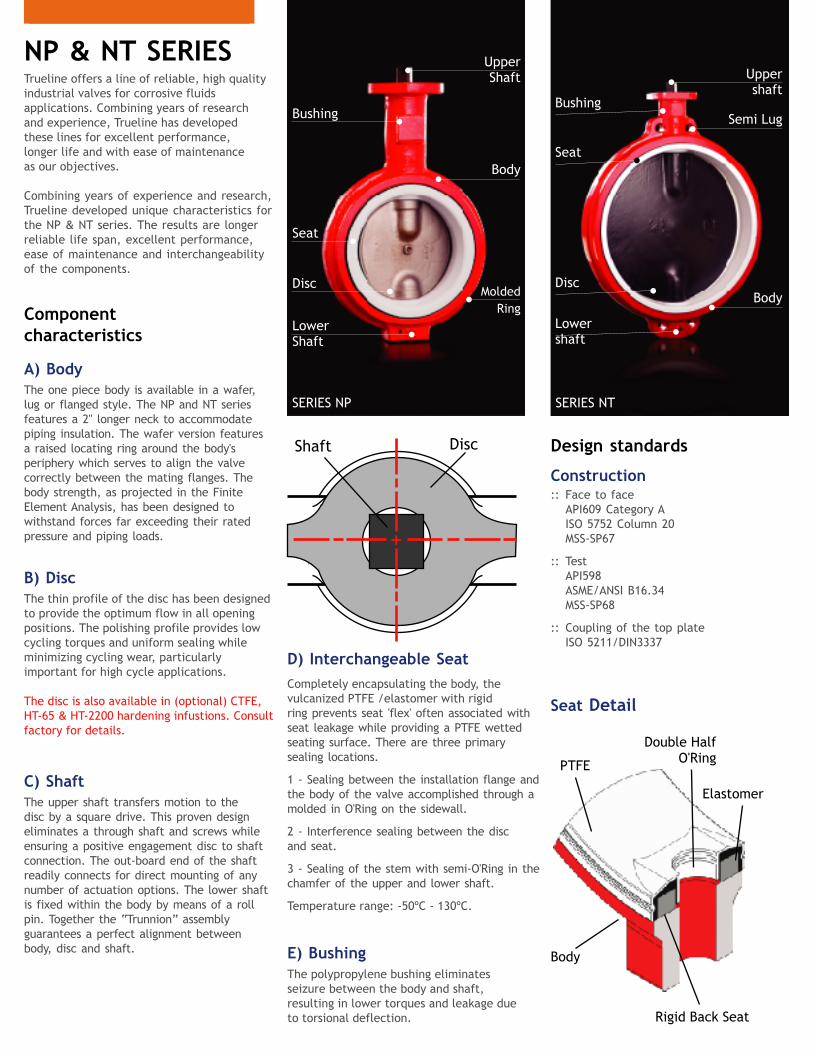
PTFE
Body
Rigid Back Seat
Double HalfO'Ring
+
Shaft Disc
Elastomer
Trueline offers a line of reliable, high quality industrial valves for corrosive fluids applications. Combining years of research and experience, Trueline has developed these lines for excellent performance, longer life and with ease of maintenance as our objectives.
Combining years of experience and research, Trueline developed unique characteristics for the NP & NT series. The results are longer reliable life span, excellent performance, ease of maintenance and interchangeability of the components.
The one piece body is available in a wafer, lug or flanged style. The NP and NT series features a 2" longer neck to accommodate piping insulation. The wafer version features a raised locating ring around the body's periphery which serves to align the valve correctly between the mating flanges. The body strength, as projected in the Finite Element Analysis, has been designed to withstand forces far exceeding their rated pressure and piping loads.
The thin profile of the disc has been designed to provide the optimum flow in all opening positions. The polishing profile provides low cycling torques and uniform sealing while minimizing cycling wear, particularly important for high cycle applications.
The disc is also available in (optional) CTFE, HT-65 & HT-2200 hardening infustions. Consult factory for details.
The upper shaft transfers motion to the disc by a square drive. This proven design eliminates a through shaft and screws while ensuring a positive engagement disc to shaft connection. The out-board end of the shaft readily connects for direct mounting of any number of actuation options. The lower shaft is fixed within the body by means of a roll pin. Together the “Trunnion” assembly guarantees a perfect alignment between body, disc and shaft.
Completely encapsulating the body, the vulcanized PTFE /elastomer with rigidring prevents seat 'flex' often associated with seat leakage while providing a PTFE wetted seating surface. There are three primary sealing locations.
1 - Sealing between the installation flange and the body of the valve accomplished through a molded in O'Ring on the sidewall.
2 - Interference sealing between the disc and seat.
3 - Sealing of the stem with semi-O'Ring in the chamfer of the upper and lower shaft.
Temperature range: -50ºC - 130ºC.
NP & NT SERIES UpperShaft
Seat
Body
LowerShaft
Disc
Bushing
MoldedRing
SERIES NP
Component characteristics
A) Body
B) Disc
C) Shaft
D) Interchangeable Seat
E) Bushing The polypropylene bushing eliminates seizure between the body and shaft, resulting in lower torques and leakage due to torsional deflection.
Seat Detail
Design standards
Uppershaft
Seat
Body
Lowershaft
Disc
BushingSemi Lug
SERIES NT
Construction:: Face to face API609 Category A ISO 5752 Column 20 MSS-SP67
:: Test API598 ASME/ANSI B16.34 MSS-SP68
:: Coupling of the top plate ISO 5211/DIN3337

Trueline Sealing System - Greater Durability
Conventional ConventionalConventional
:: Minimized elastomer contact prevents the seat from distorting, which eliminates wear and leakage.:: Integral rigid ring eliminates seat distortion. Valve may be installed in the fully closed position.:: Molded in O'Ring on seat sidewall eliminates the need for flange gaskets when used with ANSI flanges.
:: High concentration of elastomer mass in the sealing process; greater opportunity for deformation and seat tearing.:: Greater possibility to bulge through fluid absorption, causing excessive torque increases.:: Opening torques may be directly affected by incorrect installation, resulting in reduced seat life.
Disadvantages of the conventional seats
Opened ClosedPartially Open
Trueline advantages
Trueline Trueline Trueline
Finite Element Analysis NODAL SOLUTIONSTEP = 1SUB = 1TIME = 1SEQV (AVG)DMX = .569E-03SMN = 446477SMX = .525E+09
1
446477 .117E+09 .234E+09.175E+09 .292E+09
.350E+09.409E+09 .525E+09
.467E+09.587E+09
1
0.381E+08
.152E+09.762E+08.114E+09
.229E+09.267E+09 .343E+09
.305E+09.191E+09
NODAL SOLUTIONSTEP = 1SUB = 1TIME = 1SEQV (AVG)DMX = .411E-03SMN = 180588SMX = .154E+10
NODAL SOLUTIONSTEP = 1SUB = 1TIME = 1USUM (AVG)DMX = .569E-03SMX = .569-03
1
.127-03 .253E-03.190E-03 .316E-03
.380E-03.443E-03 .569E-03
.506E-03.633E-04
0
150 psi (10 Bar)
100 psi (7 Bar)
MAXIMUM PRESSURE CONDITION
2 -24*
SIZE (in) PRESSURE (psi) PRESSURE (bar)
2 -24
100
150
7
10
* For coated discs in E-CTFE.
Valves fixed between two flangeswith stainless steel disc.
Valve fastened between two flanges with disc coated in E-CTFE.
"Cold Working Pressure" (CWP)
End of Line Applications
Fluid
Gases
9 m/s 29.53 ft/s
54 m/s 177.17 ft/s
Speed limits for ON-OFF services
Flange RequirementsTrueline Valves are intended for installation between flanges according to ASME/ANSI 125/150, DIN PN10/16, NBR 7675 PN 10/16, JIS PN10. Although weld neck flanges are recommended, Trueline allows installation between slip on flanges without de-rating the pressure rating, providing the valve is correctly aligned. For dead end service with downstream flange removed, use weld neck or socket weld flanges only.
Pressure Ratings

Table: CV* Flow Coefficient - NP Series
DimensionsSERIES NP
Note: Flanged Valve follows dimensional API609A table 1.
A
E
G
N - HoleO - Bolt CircleØ
Ø
C
B
D
F
Valve type "Lug"
Detail of the top flange (ISO 5211)
Valve type "Flanged"
DIM
ENSI
ON
S
3" 5" 6"VALVE 2" 4" 10" 12"8"
B
C
D
E
F
G
H (DIN 3337)
N
O
A
ISO5211
mmin
mmin
mmin
mmin
mmin
mmin
mmin
mmin
mmin
mmin
142.905.63
216.208.51
101.604.0052.402.06
15.000.59 14
0.55ø 7/9
ø 0.28/0.35ø 50/70
ø 1.92/2.76
41.501.63
155.606.13
235.209.26
120.704.7564.202.53
47.001.85
44.201.74
161.906.37
247.809.76
133.405.2578.903.11
181.007.13
281.1011.07171.506.75
104.004.09
12.202.30
51.502.03
196.907.75
309.5012.19193.707.63
124.204.89
20.000.79 17
0.67ø 9
ø 0.35 ø 70ø 2.76
55.702.19
60.602.39
209.608.25
334.3013.16219.108.63
155.706.13
239.709.44
397.1015.63276.2010.87202.207.96
ø 9/11ø 0.35/0.43
ø 70/102ø 2.76/4.02
60.602.39
285.8011.25475.9018.74336.6013.25250.509.86
25.000.98 22
0.86ø 11
ø 0.43ø 102ø 4.02
65.602.58
309.6012.19551.7021.72406.4016.00301.4011.87
F05/F07 F07 F07/F10 F10
76.903.03
NOMINAL DIAMETER OF THE VALVE
90
80
75
70
60
50
40
30
25
2"
130
105
90
70
53
27
17
9
6
200
160
130
105
83
42
26
15
10
3"
300
240
205
160
125
63
38
22
15
4"
550
475
400
305
235
120
73
42
28
5"
1125
1000
830
625
490
250
155
88
60
6"
1950
1650
1350
1030
800
410
250
145
98
8"
3250
2725
2200
1750
1300
700
420
250
170
10"
5000
4300
3600
2750
2150
1150
670
390
260
12"
7500
6050
5000
4050
3100
1600
1000
550
380
* Orientated values for specific weight of the water = 1.0 at 20ºC.
% OF OPENING
2 1/2"
2 1/2"
2"lbkg
lbkg
lbkg
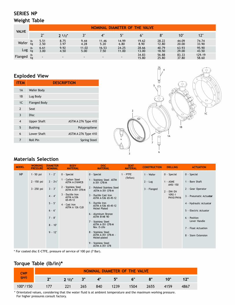
5.512.506.613.00
8.753.979.924.50
9.444.28
3"
11.025.00
11.465.20
4"
16.537.50
14.996.80
5"
24.2511.00
19.628.90
6"
28.6613.00
28.2212.80
8"
40.7918.50
44.0920.00
10"
63.9329.00
74.7433.90
12"
95.9043.50
56.8825.80
34.8315.80
83.3337.80
129.1958.60- - - - -
Weight TableSERIES NP
2
1A
3
4
5
6
7
1B
1C
Exploded ViewITEM
1A
1B
Wafer Body
Lug Body
DESCRIPTION
1C
2
3
Flanged Body
Seat
Disc
4
5
6
7
Upper Shaft
Bushing
Lower Shaft
Roll Pin
ASTM A 276 Type 410
Polypropilene
ASTM A 276 Type 410
Spring Steel
Materials Selection
NP 1 - PTFE(Teflon)
tor
r
* For coated disc E-CTFE, pressure of service of 100 psi (7 Bar).
MODEL WORKINGPRESSURE
DIAMETERNOMINAL
BODYMATERIAL
DISCMATERIAL
SEATMATERIAL DRILLINGCONSTRUCTION ACTUATION
1 -50 psi
2 -150 psi
3 -250 psi
1 - 2"
3 - 3"
4 - 4"
5 - 5"
6 - 6"
7 - 8"
8 - 10"
9 - 12"
2 - 2 "1/2
0 - Special
2 - Stainless Steel ASTM A-351 CF8-M
3 - ASTM A-536 65-45-12
Ductile Iron
1 - Carbon S ASTM A-216WCB
teel
4 - ASTM A 126 CLB
Cast Iron
0 - Special
2 -
3 - ASTM A-536 65-45-12
Ductile Cast Iron
1 - Stainless Steel ASTM A
Polished Stainless SteelASTM A-351 CF8-M
-351 CF8-M
5 - ASTM A-536 65-45-12 Nickel Plated
Ductile Iron
6 - Aluminum Bronze ASTM B148 9D
7 - Stainless Steel ASTM A-351 CF8-M Rev. E-ctfe
8 - Stainless Steel ASTM A-351 CF8
ASTM A-351 CF8
-M - Nickel-plated
9 -
Stainless Steel
1 - Wafer
3 - Flanged
2 - Lug
0 - Special
1 - ASME ANSI 150
0 - Special
2 - Gear Operator
1 - Bare Shaft
3 - Pneumatic Actuator
4 - Hydraulic Actuator
5 - Electric Actuator
6 - Position Lever Handle
7 - Float Actuation
8 - Stem Extension
2 - DIN EN 1092-1 PN10/PN16
100*/150
NOMINAL DIAMETER OF THE VALVE CWP(psi)
221
3"
265
4"
840
5"
1239
6"
1504
8"
2655
10"
4159
12"
4867
2"
177 *Orientated values, considering that the water fluid is at ambient temperature and the maximum working pressure. For higher pressures consult factory.
NOMINAL DIAMETER OF THE VALVEVALVE
Wafer
Lug
Flanged
Torque Table (lb/in)*
2 1/2"
2 1/2"
SERIES NT
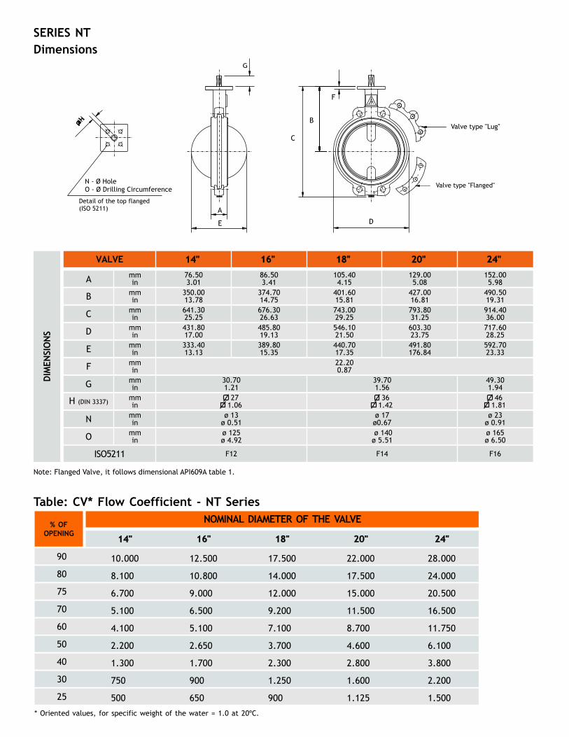
Table: CV* Flow Coefficient - NT Series
Dimensions
Note: Flanged Valve, dimensional API609A table 1.it follows
G
A
E
C
B
D
F
N - HoleO - Drilling CircumferenceØ
Ø
Detail of the top flanged (ISO 5211)
Valve type "Lug"
Valve type "Flanged"
DIM
ENSI
ON
S
16" 18" 24"VALVE 14" 20"
B
C
D
E
F
G
H (DIN 3337)
N
O
A
ISO5211
mmin
mmin
mmin
mmin
mmin
mmin
mmin
mmin
mmin
mmin
350.0013.78641.3025.25431.8017.00333.4013.13
30.701.21 27
1.06ø 13
ø 0.51ø 125ø 4.92
76.503.01
374.7014.75676.3026.63485.8019.13389.8015.35
86.503.41
105.404.15
401.6015.81743.0029.25546.1021.50440.7017.35
427.0016.81793.8031.25603.3023.75491.80176.84
22.200.87
129.005.08
490.5019.31914.4036.00717.6028.25592.7023.33
39.701.56 36
1.42ø 17ø0.67 ø 140ø 5.51
152.005.98
49.301.94 46
1.81ø 23
ø 0.91ø 165ø 6.50
F12 F14 F16
NOMINAL DIAMETER OF THE VALVE
90
80
75
70
60
50
40
30
25
10.000
8.100
6.700
5.100
4.100
2.200
1.300
750
500
14"
12.500
10.800
9.000
6.500
5.100
2.650
1.700
900
650
16"
17.500
14.000
12.000
9.200
7.100
3.700
2.300
1.250
900
18"
22.000
17.500
15.000
11.500
8.700
4.600
2.800
1.600
1.125
20"
28.000
24.000
20.500
16.500
11.750
6.100
3.800
2.200
1.500
24"
% OFOPENING
* Oriented values, for specific weight of the water = 1.0 at 20ºC.

SERIES NT
Exploded View
Materials Selection
Weight Table
14" 16" 18" 20" 24"lbkg
lbkg
lbkg
132.2860.00
176.3780.00
233.69106.00268.96122.00286.60130.00
302.03137.00361.56164.00407.85185.00
421.08191.00507.06230.00540.13245.00
211.6496.00227.08103.00
158.7372.00182.9883.00
ITEM
1C
2
Flanged Body
Seat
DESCRIPTION
3
4
5
Disc
6
7
8
9
Upper Shaft
Elastic Pin
ASTM A 276 Type 410
Lower Bushing Copper
Lower Shaft ASTM A 276 Type 410
Spring Steel
Upper Bushing Copper
Retention Bushing Copper
1A
1B
Wafer Body
Lug Body
2
1A
4
6
8
1B
1C
5
9
7
3
NT 1 - PTFE(Teflon)
tor
r
* For coated disc E-CTFE, pressure of service of 100 psi (7 Bar).
MODEL WORKINGPRESSURE
DIAMETERNOMINAL
BODYMATERIAL
DISCMATERIAL
SEATMATERIAL DRILLINGCONSTRUCTION ACTUATION
1 -50 psi
2 -150 psi
3 -250 psi
1 - 14"
3 - 18"
4 - 20"
5 - 24"
2 - 16"
0 - Special
2 - Stainless Steel ASTM A-351 CF8-M
3 - ASTM A-536 65-45-12
Ductile Iron
1 - Carbon S ASTM A-216WCB
teel
4 - ASTM A 126 CLB
Cast Iron
0 - Special
2 -
3 - ASTM A-536 65-45-12
Ductile Cast Iron
1 - Stainless Steel ASTM A
Polished Stainless SteelASTM A-351 CF8-M
-351 CF8-M
5 - ASTM A-536 65-45-12 Nickel Plated
Ductile Iron
6 - Aluminum Bronze ASTM B148 9D
7 - Stainless Steel ASTM A-351 CF8-M Rev. E-ctfe
8 - Stainless Steel ASTM A-351 CF8
ASTM A-351 CF8
-M - Nickel-plated
9 -
Stainless Steel
1 - Wafer
3 - Flanged
2 - Lug
0 - Special
1 - ASME ANSI 150
0 - Special
2 - Gear Operator
1 - Bare Shaft
3 - Pneumatic Actuator
4 - Hydraulic Actuator
5 - Electric Actuator
7 - Float Actuation
8 - Stem Extension
2 - DIN EN 1092-1 PN10/PN16
Diam. Valv.
100**/150 psi 7626
14"
9204
16"
12302
18"
16462
20"
25667
24"
NOMINAL DIAMETER OF THE VALVEVALVE
Wafer
Lug
Flanged
Torque Table (lb/in)*
*Orientated values, considering that the water fluid is at ambient temperature and the maximum working pressure.**For records coated in E-CTFE. For higher pressures consult factory.
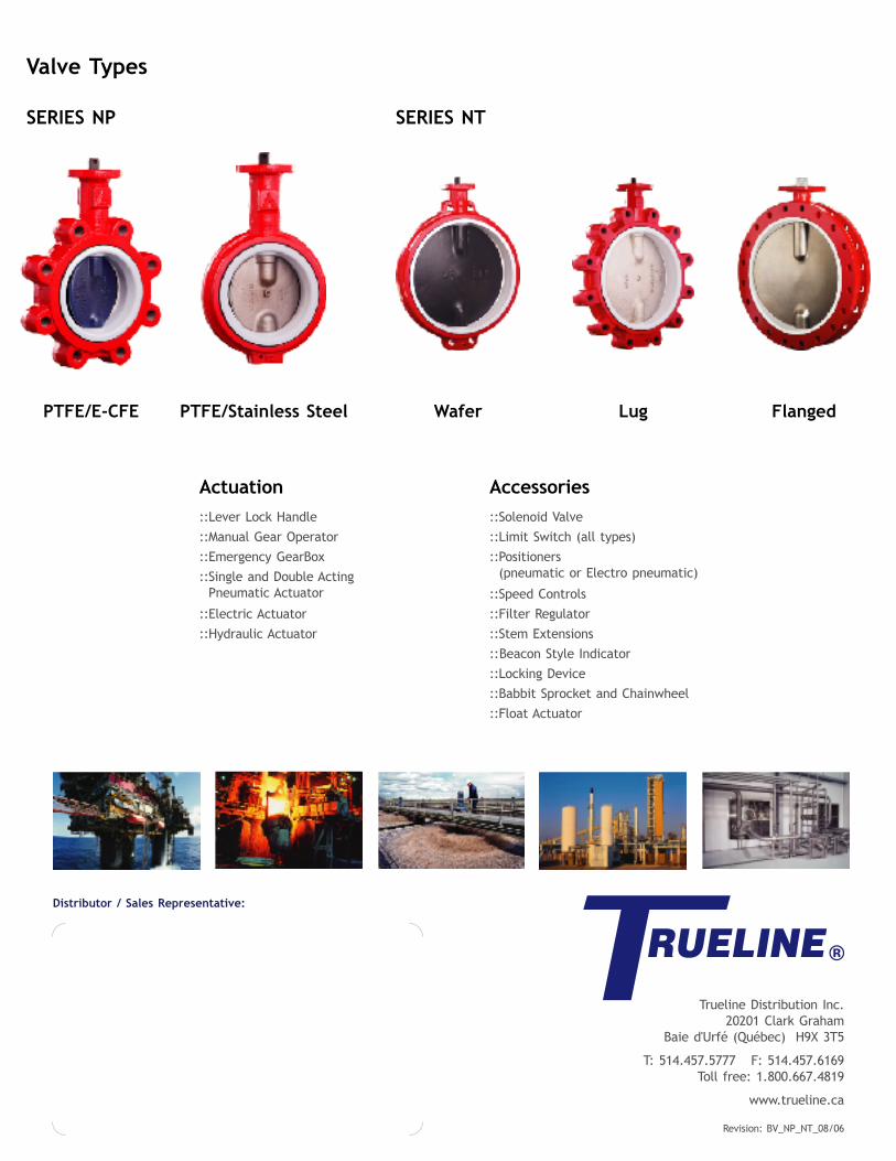
PTFE/E-CFE PTFE/Stainless Steel
Actuation::Lever Lock Handle
::Manual Gear Operator
::Emergency GearBox
::Single and Double Acting Pneumatic Actuator
::Electric Actuator
::Hydraulic Actuator
Accessories::Solenoid Valve
::Limit Switch (all types)
::Positioners (pneumatic or Electro pneumatic)
::Speed Controls
::
::
Filter Regulator
::Stem Extensions
Beacon Style Indicator
::Locking Device
::Babbit Sprocket and Chainwheel
::Float Actuator
Valve Types
SERIES NP SERIES NT
FlangedWafer Lug
Distributor / Sales Representative:
Trueline Distribution Inc.20201 Clark Graham
Baie d'Urfé (Québec) H9X 3T5
T: 514.457.5777 F: 514.457.6169Toll free: 1.800.667.4819
www.trueline.ca
Revision: BV_NP_NT_08/06


![9103 - IDROBI · 9103 2017-08 1/ 1 9103 DN Dz D PN16 (PN10) K PN16 (PN10) d l x n PN16 (PN10) f C L Weight [kg] 50 63 165 125 102 19x4 3 19 90 3,8 80 90 200 160 138 19x8(4) 3 19 95](https://static.documents.pub/doc/80x56/5e3eae917d68ff58f40a2bd4/9103-idrobi-9103-2017-08-1-1-9103-dn-dz-d-pn16-pn10-k-pn16-pn10-d-l-x-n-pn16.jpg)


