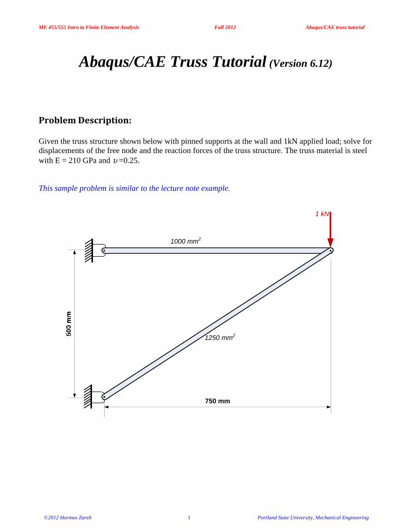
Problem Description: Given the truss structure shown below with pinned supports at the wall and 1kN applied load; solve for displacements of the free node and the reaction forces of the truss structure. The truss material is steel with E = 210 GPa and υ =0.25. This sample problem is similar to the lecture note example.
1000 mm2
1250 mm2
750 mm
1 kN
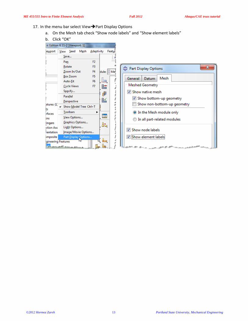
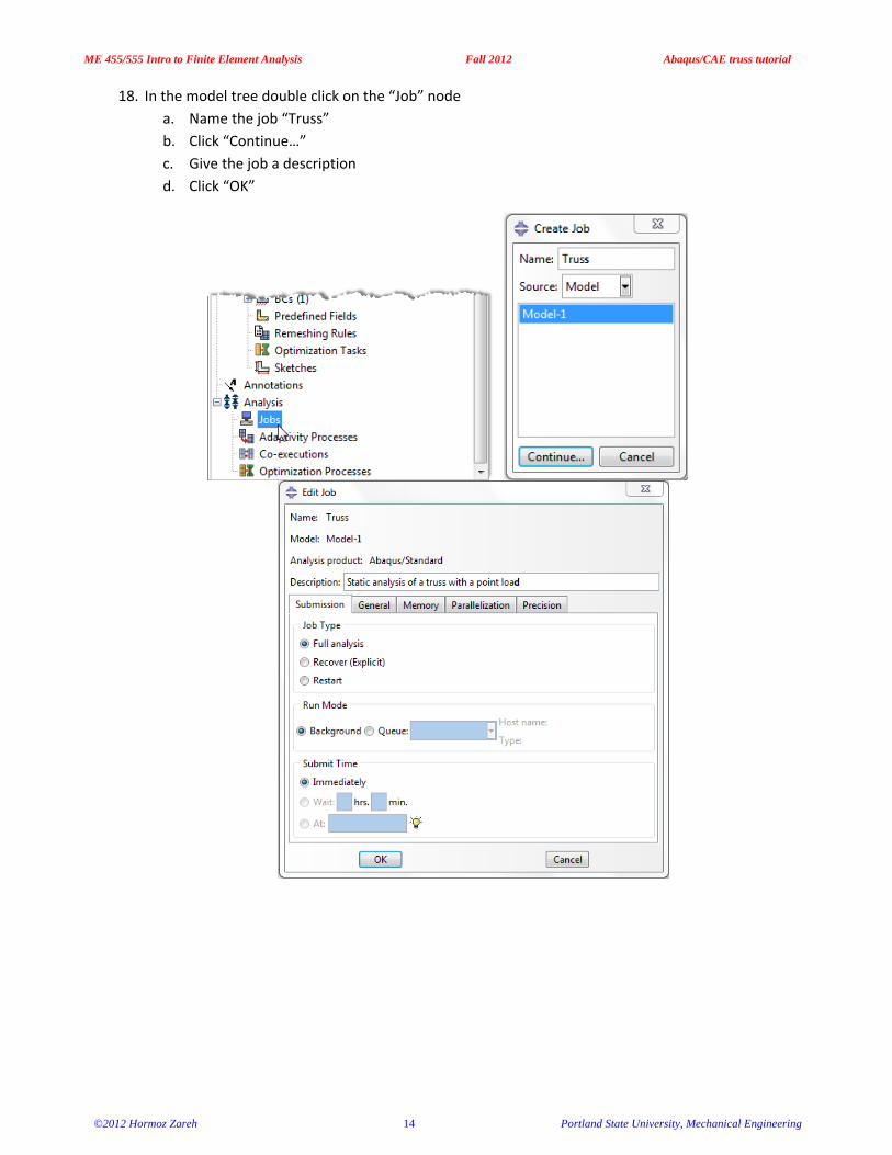
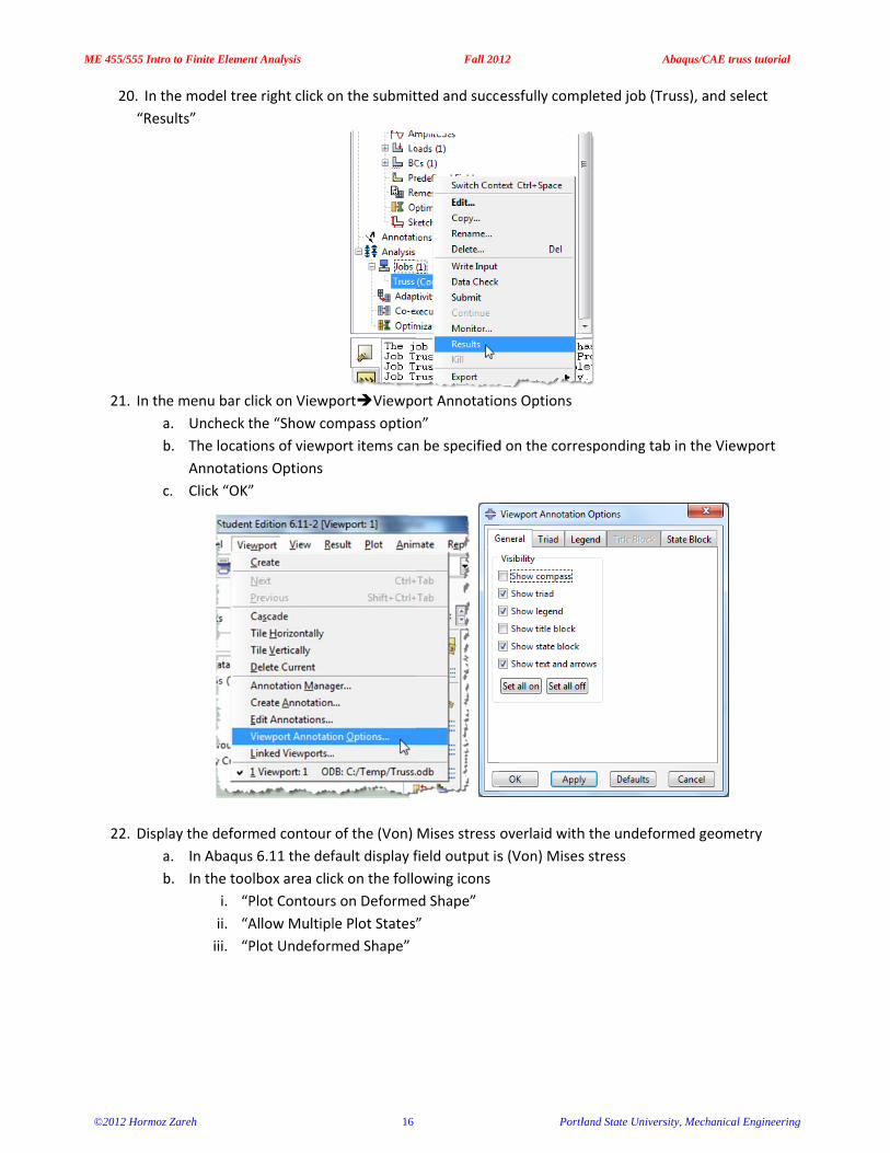
ME 455/555 Intro to Finite Element Analysis Fall 2012 Abaqus/CAE truss tutorial
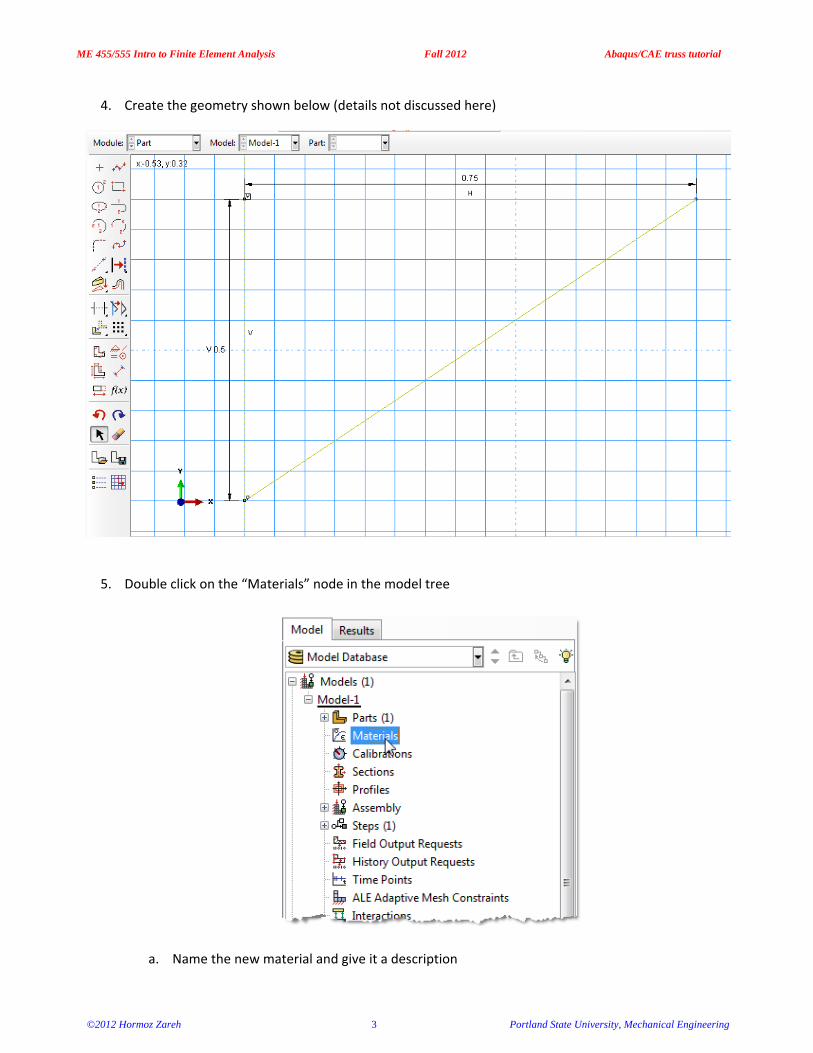
2. In the model tree double click on the “Parts” node (or right click on “parts” and select Create)
3. In the Create Part dialog box (shown above) name the part and a. Select “2D Planar” b. Select “Deformable” c. Select “Wire” d. Set approximate size = 1 e. Click “Continue…”
ME 455/555 Intro to Finite Element Analysis Fall 2012 Abaqus/CAE truss tutorial
6. Double click on the “Sections” node in the model tree
a. Name the section “HorizontalBar” and select “Beam” for both the category and “Truss” for the type
b. Click “Continue…” c. Select the material created above (Steel) d. Set cross-sectional area = 0.001 (base SI units, m2) e. Click “OK”
f. Repeat for the “AngledBar” i. Cross-sectional area=0.00125
7. Expand the “Parts” node in the model tree, expand the node of the part just created, and double click
on “Section Assignments” a. Select the horizontal portion of the geometry in the viewport b. Click “Done” c. Select the “HorizontalBar” section created above d. Click “OK”
e. Repeat for the angled portion of the geometry
ME 455/555 Intro to Finite Element Analysis Fall 2012 Abaqus/CAE truss tutorial
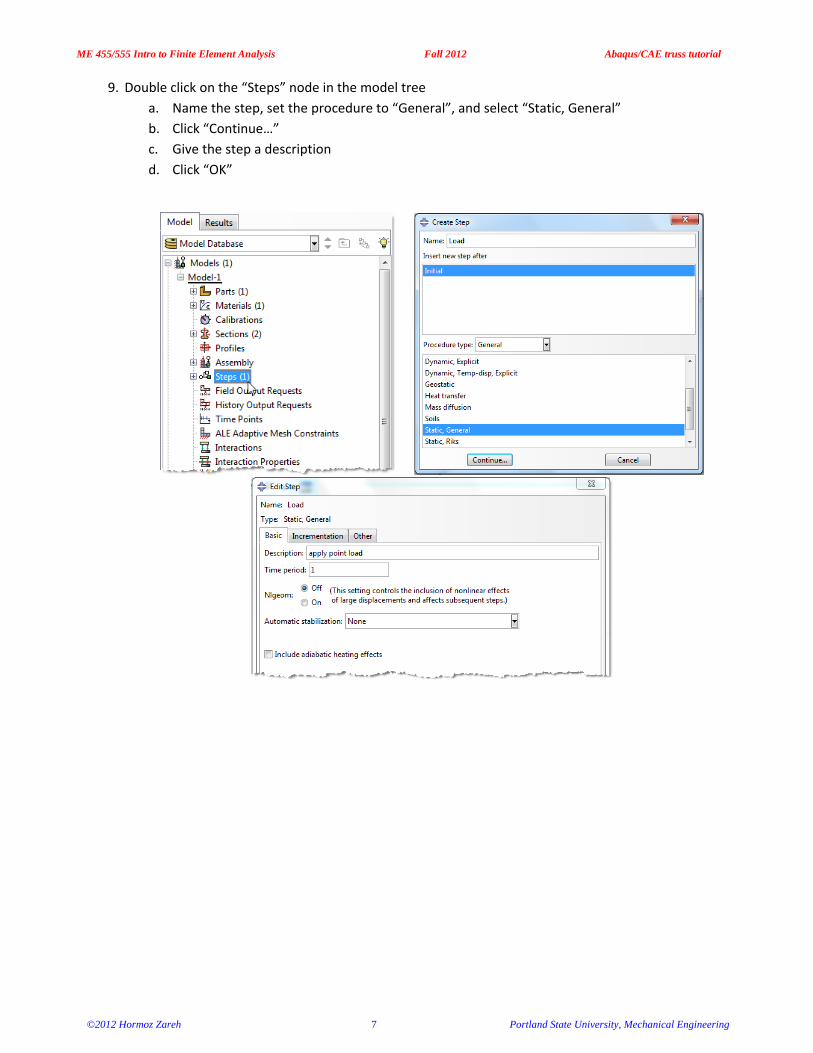
9. Double click on the “Steps” node in the model tree a. Name the step, set the procedure to “General”, and select “Static, General” b. Click “Continue…” c. Give the step a description d. Click “OK”
ME 455/555 Intro to Finite Element Analysis Fall 2012 Abaqus/CAE truss tutorial
10. Expand the Field Output Requests node in the model tree, and then double click on F-Output-1 (F-Output-1 was automatically generated when creating the step)
a. Uncheck the variables “Strains” and “Contact” b. Click “OK”
11. Expand the History Output Requests node in the model tree, and then right click on H-Output-1 (H-
Output-1 was automatically generated when creating the step) and select Delete
ME 455/555 Intro to Finite Element Analysis Fall 2012 Abaqus/CAE truss tutorial
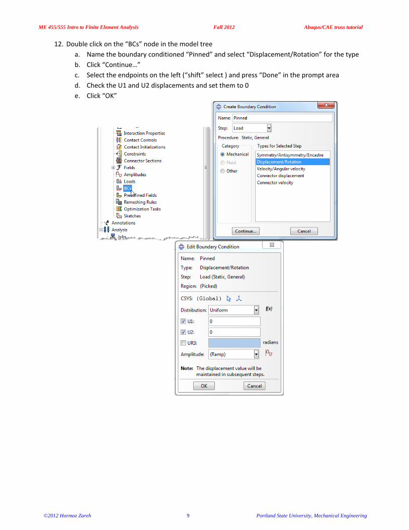
12. Double click on the “BCs” node in the model tree a. Name the boundary conditioned “Pinned” and select “Displacement/Rotation” for the type b. Click “Continue…” c. Select the endpoints on the left (“shift” select ) and press “Done” in the prompt area d. Check the U1 and U2 displacements and set them to 0 e. Click “OK”
ME 455/555 Intro to Finite Element Analysis Fall 2012 Abaqus/CAE truss tutorial
13. Double click on the “Loads” node in the model tree a. Name the load “PointLoad” and select “Concentrated force” as the type b. Click “Continue…” c. Select the vertex on the right and press “Done” in the prompt area d. Specify CF2 = -1000 e. Click “OK”
ME 455/555 Intro to Finite Element Analysis Fall 2012 Abaqus/CAE truss tutorial
14. In the model tree double click on “Mesh” for the Truss part, and in the toolbox area click on the “Assign Element Type” icon
a. Select “Standard” for element type b. Select “Linear” for geometric order c. Select “Truss” for family d. Note that the name of the element (B21) and its description are given below the element
controls e. Click “OK”
ME 455/555 Intro to Finite Element Analysis Fall 2012 Abaqus/CAE truss tutorial
19. In the model tree right click on the job just created (Truss) and select “Submit a. While Abaqus is solving the problem right click on the job submitted (Truss), and select
“Monitor”
b. In the Monitor window check that there are no errors or warnings i. If there are errors, investigate the cause(s) before resolving
ii. If there are warnings, determine if the warnings are relevant, some warnings can be safely ignored
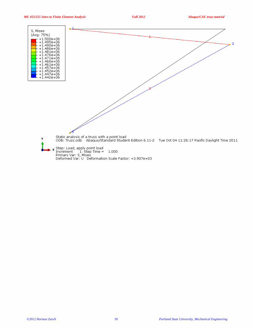
23. In the toolbox area click on the “Common Plot Options” icon
a. Note that the Deformation Scale Factor can be set on the “Basic” tab b. On the “Labels” tab check “Show element labels”, “Show node labels”, and “Show node
symbols” i. *Note* the default label colors may need to be adjusted for visibility. They can be
changed in this option box by clicking on the color and picking a new one. c. Click “OK”
ME 455/555 Intro to Finite Element Analysis Fall 2012 Abaqus/CAE truss tutorial
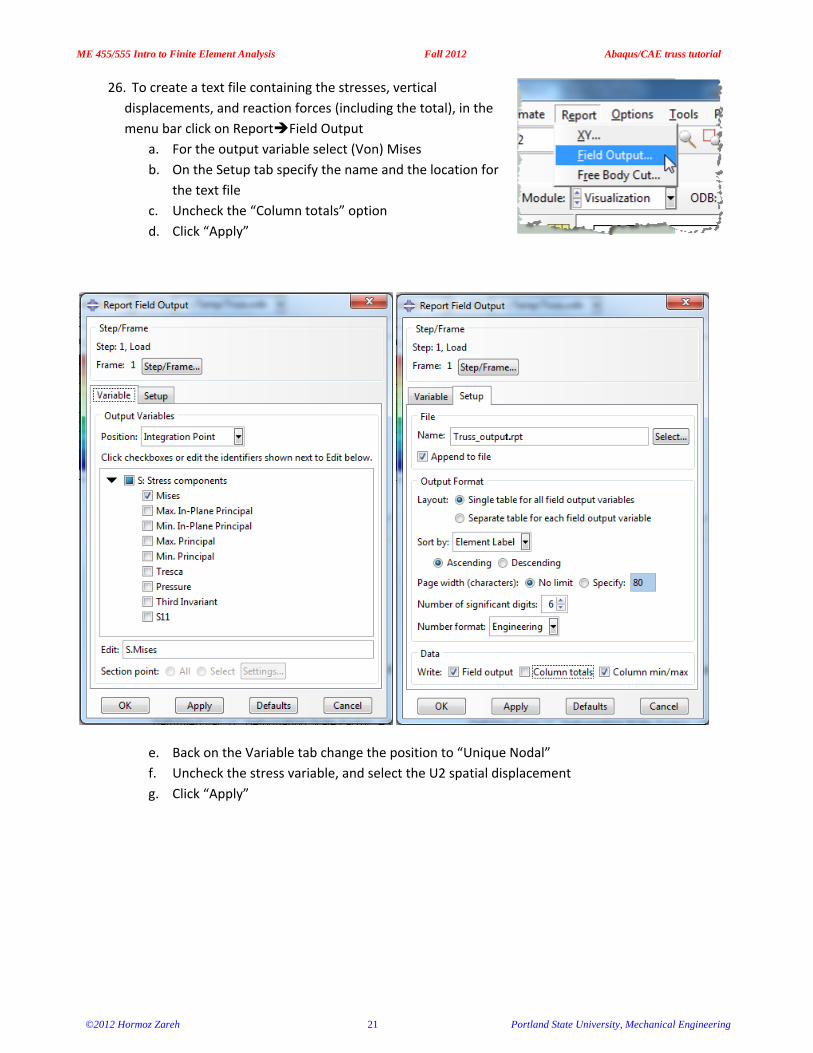
26. To create a text file containing the stresses, vertical displacements, and reaction forces (including the total), in the menu bar click on Report Field Output
a. For the output variable select (Von) Mises b. On the Setup tab specify the name and the location for
the text file c. Uncheck the “Column totals” option d. Click “Apply”
e. Back on the Variable tab change the position to “Unique Nodal” f. Uncheck the stress variable, and select the U2 spatial displacement g. Click “Apply”
ME 455/555 Intro to Finite Element Analysis Fall 2012 Abaqus/CAE truss tutorial
h. On the Variable tab, uncheck Spatial displacement and select the RF2 reaction force i. On the Setup tab, check the “Column totals” option j. Click “OK”
ME 455/555 Intro to Finite Element Analysis Fall 2012 Abaqus/CAE truss tutorial
27. Open the .rpt file with any text editor (such as Notepad) a. One thing to check is that the total downward reaction force is equal to the applied load
(1,000 N) b. Each time “Apply” is pressed the .rpt file is updated as long as the “Append to file” option is