European Telecommunications Standards Institute TS 101 010 V1.1.1 (1997-11) Technical Specification Transmission and Multiplexing (TM); Synchronous Digital Hierarchy (SDH); Network protection schemes; Interworking: rings and other schemes
4 Definitions and classifications .................................................................................................................74.1 General definitions............................................................................................................................................. 74.2 Ring Definitions................................................................................................................................................. 94.3 Classification of network recovery schemes ...................................................................................................... 94.4 Protection partitioning and layering................................................................................................................... 94.4.1 Introduction.................................................................................................................................................. 94.4.1.1 Protection partitioning concept............................................................................................................. 104.4.1.2 Protection layering concept .................................................................................................................. 104.4.2 Definition of protection layer ..................................................................................................................... 104.4.3 Protection interworking architectures......................................................................................................... 104.4.3.1 Intra-layer network protection architecture........................................................................................... 114.4.3.2 Inter-layer network protection architecture........................................................................................... 13
5 Protection interworking objectives ........................................................................................................155.1 Traffic availability ........................................................................................................................................... 155.2 Protection independence .................................................................................................................................. 165.3 Fault coverage.................................................................................................................................................. 165.3.1 Defects related to signal loss ...................................................................................................................... 175.3.2 Defects related to signal degradation ......................................................................................................... 175.3.3 Defects related to misprovisioning............................................................................................................. 175.4 Interconnecting subnetworks protected at different layers............................................................................... 175.5 Capability to interconnect networks using different protection schemes ......................................................... 185.6 Minimisation of traffic interruption ................................................................................................................. 185.7 Operation modes.............................................................................................................................................. 185.8 Capacity utilisation .......................................................................................................................................... 18
6 Subnetwork interconnection architectures.............................................................................................226.1 Single node interconnecting architecture ......................................................................................................... 226.2 Dual node interconnecting architectures .......................................................................................................... 226.2.1 Mechanisms to implement dual node interconnecting architectures...........................................................226.2.1.1 Virtual ring interconnecting architecture .............................................................................................. 236.2.1.2 Drop and continue interconnecting....................................................................................................... 236.3 Application of interworking architectures on real network topologies ............................................................ 24
7 Interworking between similar protection schemes.................................................................................267.1 MS SPRING .................................................................................................................................................... 267.1.1 Two MS shared protection rings connected by one node........................................................................... 267.1.2 Two MS shared protection rings connected by two nodes ......................................................................... 287.2 LO/HO trail protection..................................................................................................................................... 317.2.1 VC trail protected subnetworks interconnected by one node ..................................................................... 317.2.2 Two VC trail protected subnetworks interconnected by two nodes ........................................................... 347.3 LO/HO subnetwork connection protection ...................................................................................................... 377.3.1 SNC protected subnetworks interconnected by one node........................................................................... 377.3.2 Two SNC-P Subnetworks Interconnected by Two Nodes.......................................................................... 41
8 Interworking between different protection schemes..............................................................................478.1 Dual node interworking between MS-SPRING and SNC-P subnetworks ....................................................... 478.2 Single Node Interworking between MS-SPRING and SNC-P......................................................................... 49
TS 101 010 V1.1.1 (1997-11)4
9 Comparison of protection interconnection schemes..............................................................................51
10 Network applications .............................................................................................................................5210.1 Interconnecting ring subnetworks with 4/3/1 Digital Cross-Connects ............................................................. 5210.2 Stacked ring configuration ............................................................................................................................... 5310.3 Interworking of protection between networks belonging to different operators .............................................. 54
11 Conclusions and recommendations........................................................................................................56
Annex A ...........................................................................................................................................................58A.1 Introduction...................................................................................................................................................... 58A.1.1 Protection independence ............................................................................................................................ 58A.1.2 Routing....................................................................................................................................................... 59A.2 MS-SPRING to SNCP dual node drop and continue subnetwork interconnection.......................................... 60A.2.1 Normal conditions...................................................................................................................................... 60A.2.2 Failure in MS SPRing Primary interconnection node I1 ............................................................................ 61A.2.3 Failure in MS SPRing Primary interconnection node I1. Node failure in SNCP subnetwork .................... 62A.2.4 Failure in MS SPRing Primary interconnection node I1. Cable cut in SNCP subnetwork......................... 63A.2.5 Failure in one interconnection link............................................................................................................. 64A.3 MS-SPRING to MS-SPRING dual node drop and continue subnetwork interconnection............................... 65A.3.1 Normal conditions...................................................................................................................................... 65A.3.2 Failure in MS SPRing 1 Primary interconnection node I1 ......................................................................... 66A.3.3 Failure in MS SPRing 1 Primary interconnection node I1. Node failure in MS SPRing 2 ........................ 67A.3.4 Failure in MS SPRing 1 Primary interconnection node I1. Cable cut in MS SPRing 2 ............................. 68A.3.5 Failure in one interconnection link............................................................................................................. 69A.4 SNCP to SNCP dual node drop and continue subnetwork interconnection ..................................................... 70A.4.1 Normal conditions...................................................................................................................................... 70A.4.2 Failure in SNCP subnetwork 1 interconnection node I1 ............................................................................ 71A.4.3 Failure in SNCP subnetwork 1 interconnection node I1. Node failure in SNCP subnetwork 2 ................. 72A.4.4 Failure in SNCP subnetwork 1 interconnection node I1. Cable cut in SNCP subnetwork 2 ...................... 73A.4.5 Failure in one interconnection link............................................................................................................. 74
Annex B (informative): Bibliography...................................................................................................75
Intellectual Property RightsIPRs essential or potentially essential to the present document may have been declared to ETSI. The informationpertaining to these essential IPRs, if any, is publicly available for ETSI members and non-members, and can be foundin ETR 314: "Intellectual Property Rights (IPRs); Essential, or potentially Essential, IPRs notified to ETSI in respect ofETSI standards", which is available free of charge from the ETSI Secretariat. Latest updates are available on the ETSIWeb server (http://www.etsi.fr/ipr).
Pursuant to the ETSI Interim IPR Policy, no investigation, including IPR searches, has been carried out by ETSI. Noguarantee can be given as to the existence of other IPRs not referenced in ETR 314 (or the updates onhttp://www.etsi.fr/ipr) which are, or may be, or may become, essential to the present document.
ForewordThis Technical Specification (TS) has been produced by ETSI Technical Committee Transmission and Multiplexing(TM) in order to give guidance to network operators and equipment manufacturers on the Synchronous DigitalHierarchy (SDH) network protection interworking, based on rings and other schemes.
The present document is one of a family of related TSs and European Telecommunications Standards (ETSs) coveringthe various aspects of SDH protection:
TS 101 009: "Transmission and Multiplexing (TM); Synchronous Digital Hierarchy (SDH); Network protectionschemes; Types and characteristics".
TS 101 010: "Transmission and Multiplexing (TM); Synchronous Digital Hierarchy (SDH); Network protectionschemes; Interworking: rings and other schemes".
ETS 300 746: "Transmission and Multiplexing (TM); Synchronous Digital Hierarchy (SDH); Network protectionschemes; Automatic Protection Switch (APS) protocols and operation".
TS 101 010 V1.1.1 (1997-11)6
1 ScopeThe present document describes the criteria, principles, objectives, requirements and architectures of protectioninterworking between multiplex section shared protected rings, multiplex section linear protection, and HigherOrder/lower Order (HO/LO) Virtual Container (VC) trail and subnetwork connection protection schemes. The SDHprotection interworking scenarios between the same and different protection schemes are described.
The network objectives, architectures, functional modelling and operations of the various SDH protection schemes aredescribed in TS 101 009 [1]. The protection switching initiation criteria and the Automatic Protection Switching (APS)protocols of the various SDH protection schemes are specified in ETS 300 746 [2].
2 Normative referencesReferences may be made to:
a) specific versions of publications (identified by date of publication, edition number, version number, etc.), inwhich case, subsequent revisions to the referenced document do not apply; or
b) all versions up to and including the identified version (identified by "up to and including" before the versionidentity); or
c) all versions subsequent to and including the identified version (identified by "onwards" following the versionidentity); or
d) publications without mention of a specific version, in which case the latest version applies.
A non-specific reference to an ETS shall also be taken to refer to later versions published as an EN with the samenumber.
[1] TS 101 009 V1.1.1: "Transmission and Multiplexing (TM);Synchronous Digital Hierarchy (SDH);Network protection schemes; Types and characteristics".
[2] ETS 300 746: "Transmission and Multiplexing (TM); Synchronous Digital Hierarchy (SDH);Network protection schemes; Automatic Protection Switch (APS) protocols and operation".
[3] ITU-T Recommendation G.803: "Architectures of transport networks based on the synchronousdigital hierarchy (SDH)".
[4] ITU-T Recommendation G.707: "Network Node Interface for the Synchronous Digital Hierarchy(SDH)".
[5] ITU-T Recommendation G.783: "Characteristics of synchronous digital hierarchy (SDH)equipment functional blocks".
[6] ITU-T Recommendation G.841: "Types and Characteristics of SDH Network ProtectionArchitectures".
[7] ITU-T Recommendation G.842: "Interworking of SDH Network Protection Architectures".
3 AbbreviationsFor the purposes of the present document, the following definitions apply:
ADM Add Drop MultiplexAIS Alarm Indication SignalAPS Automatic Protection SwitchingAU Administrative UnitAUG Administrative Unit GroupAU-n Administrative Unit (level) n
TS 101 010 V1.1.1 (1997-11)7
BER Bit Error RatioDXC Digital cross-ConnectHO Higher OrderLO Lower OrderLOF Loss Of FrameLOS Loss Of SignalMS Multiplex SectionMS-SPRING Multiplex Section Shared Protection RINGsNA Not ApplicableNC-P / I Network Connection Protection / Inherent monitoringNC-P / N Network Connection Protection / Non-intrusive monitoringNE Network ElementPOH Path OverHeadRDI Remote Defect IndicationRS Regenerator SectionSD Signal DegradeSDH Synchronous Digital HierarchySF Signal FailSNC Sub-Network ConnectionSNC-P Sub-Network Connection-ProtectionSNC-P / I Sub-Network Connection Protection / Inherent monitoringSNC-P / N Sub-Network Connection Protection / Non-intrusive monitoringSTM Synchronous Transport ModuleSTM-N Synchronous Transport Module (level) NTIM Trace Identifier MismatchTTI Trail Trace IdentifierTU Tributary UnitTUG Tributary Unit GroupUNEQ UNEQuipped indicationVC Virtual ContainerVC-n Virtual Container (level) nWTR Wait To Restore
4 Definitions and classifications
4.1 General definitionsFor the purposes of the present document, the following definitions apply:
Administrative Unit (AU): See ITU-T Recommendation G.707 [4].
Administrative Unit Group (AUG): See ITU-T Recommendation G.707 [4].
Automatic Protection Switching (APS): See ITU-T Recommendation G.783 [5].
Bi-directional operation: Synonym for dual ended operation.
Bit Interleaved Parity (BIP): See ITU-T Recommendation G.707 [4].
bridge: The action of transmitting identical traffic on both the working and protection trails.
dedicated protection: See ITU-T Recommendation G.803 [3].
disjointed routes: These are routes which use different fibre ducts and through different nodes to avoid single points offailure.
drop and continue: A function within a ring node where traffic is both extracted from the working channels on the ring(drop), and transmitted onwards on the ring (continue).
TS 101 010 V1.1.1 (1997-11)8
dual ended operation: See TS 101 009 V1.1.1 [1].
NOTE: The dual ended operation is synonymous of bi-directional switching, the same can be said about singleended operation and unidirectional switching.
extra traffic: Traffic that is carried over the protection trail when it is not used for the protection of working traffic:This is sometimes called secondary traffic. Extra traffic is not protected and is pre-empted when the protection trail isrequired to protect the working traffic.
Loss Of Frame (LOF): See ITU-T Recommendation G.783 [5].
Loss Of Signal (LOS): See ITU-T Recommendation G.783 [5].
Multiplex Section (MS): See ITU-T Recommendation G.803 [3].
Multiplex Section AIS (MS-AIS): See ITU-T Recommendation G.783 [5].
Multiplex Section RDI (MS-RDI): See ITU-T Recommendation G.707 [4].
Network Connection Protection (NC-P): Network connection protection is the largest subnetwork connectionprotection that can be established between two trail terminating equipment.
Path Overhead (POH): See ITU-T Recommendation G.707 [4].
primary interconnection node: It is an interconnection node in a dual node interconnection MS-SPRING architectureusing drop and continue containing the switch and drop and continue function.
protection trail: The trail allocated to transport the working traffic during a switch event: When there is a switch event,traffic on the affected working trail is bridged onto the protection trail.
Regenerator Section (RS): See ITU-T Recommendation G.803 [3].
restoration: See ITU-T Recommendation G.803 [3].
secondary interconnection node: It is an interconnection node in a dual node interconnection MS-SPRINGarchitecture using drop and continue containing only aggregate to tributary connection functions.
secondary traffic See extra traffic.
Section Overhead (SOH): See ITU-T Recommendation G.707 [4].
shared protection: See ITU-T Recommendation G.803 [3].
single ended operation: See TS 101 009/V1.1.1 [1].
single point failure: Failure [ai1][ai2] located at a single physical point in a ring: The failure may affect one or morefibres. A single point failure may be detected by any number of nodes.
sub-network connection: See ITU-T Recommendation G.803 [3].
sub-network connection protection: See ITU-T Recommendation G.803 [3].
switch: The action of selecting traffic from the protection trail rather than the working trail.
tail-end: The node that requests the bridge.
trail: See ITU-T Recommendation G.803 [3].
trail protection: See ITU-T Recommendation G.803 [3].
Tributary Unit (TU): See ITU-T Recommendation G.707 [4].
Tributary Unit Group (TUG): See ITU-T Recommendation G.707 [4].
Uni-directional operation: Synonym for single ended operation.
Virtual Container (VC): See ITU-T Recommendation G.707 [4].
TS 101 010 V1.1.1 (1997-11)9
Wait To Restore (WTR): The condition in which a working trail meets the restoral threshold after an SD or SFcondition. The transport of working traffic is ready to be reverted to the working trail from the protection trail.
working traffic: Traffic that is normally carried in a working trail, except in the event of a protection switch.
working trail: The trail over which working traffic is transported when there is no switch events.
4.2 Ring DefinitionsFor the purposes of the present document, the following definitions apply:
add traffic: Traffic that is inserted into a working trail at a ring node.
drop traffic: Traffic that is extracted from a working trail at a ring node.
ring: A ring is constructed within a layer consisting of a set of nodes, each of which is connected to its immediateneighbour (adjacent) nodes by a trail/link connection, forming a closed loop. The capacity between any pair of nodes ofthe ring is the same.
span: The set of multiplex sections between two adjacent nodes on a ring.
4.3 Classification of network recovery schemesThis subclause describes the architectural features of the main strategies which may be used to enhance the availabilityof a transport network. This enhancement is achieved by the replacement of failed or degraded transport entities. Thereplacement is normally initiated by the detection of a defect, performance degradation or an external managementrequest.
Protection: This makes use of pre-assigned capacity between the nodes. The simplest architecture has one dedicatedprotection entity for each working entity (1+1). The most complex architecture has m protection entities shared amongstn working entities (m:n).
Restoration: This makes use of any capacity available between nodes. In general the algorithms used for restorationwill involve re-routing. When restoration is used some percentage of the transport network capacity will be reserved forre-routing working traffic.
4.4 Protection partitioning and layering
4.4.1 Introduction
A telecommunication network could be implemented using many protection schemes simultaneously to achieve thetraffic availability and speed of restoration objectives required for each kind of service supported.
A network having to satisfy such a variety of traffic survivability requirements could be modelled using the layering andpartitioning principles.
Hence, the protected transport network can be decomposed into a number of independent transport network layers with aclient/server association between adjacent layers. Thus the concepts of partitioning and layering are orthogonal as shownin figure 3.5 of ITU-T Recommendation G.803 [3].
TS 101 010 V1.1.1 (1997-11)10
4.4.1.1 Protection partitioning concept
The partitioning concept is important as a framework for defining:
a) significant administrative boundaries between network operators jointly providing end-to-end trail or networkconnection within a single layer with the objective of confining the protection actions to the network where thefailure occurred;
b) domain boundaries within the layer network of a single operator with a view to increase the overall networkresilience.
4.4.1.2 Protection layering concept
The layering concept of the transport network is based on the following assumptions:
a) each protection sublayer can be classified into similar functions;
b) it is simpler to design and operate each protection sublayer separately than it is to design and operate the entiretransport network as a single entity;
c) a protection sublayer provides autonomous capabilities such as automatic protection switching, traffic restorationagainst malfunctions or failures, human errors and management misoperations. Each layer is able to have its ownoperations and maintenance capability such as protection switching and automatic failure recovery againstmalfunctions or failures and mis-operations due to human errors.
Unlike the transport layers, the protection sublayers tend to interact with each other, hence a protection control strategymay be required to optimise the overall protected network behaviour.
4.4.2 Definition of protection layer
Subnetwork connection protection and trail APS with diverse routing, self healing rings and service re-routing usingreconfigurable DXCs are few examples of survivable architectures for the telecommunication network. Each one ofthese architectures can be modelled as a protection layer as they fit in the definition of the protection layering concept.
The following mechanisms could be modelled as protection layers:
a) the replacement of a protected trail with a protecting trail if the former fails or its performance falls below therequired level;
b) the replacement of a protected subnetwork connection with a protecting subnetwork connection if the former failsor its performance falls below the required level;
c) the replacement of a protected trail with a protecting trail if the former fails or its performance falls below therequired level by means of a re-routing algorithm.
4.4.3 Protection interworking architectures
The basic inter-working architectures and sub-architectures are:
The intra-layer network protection architecture protects traffic by using one or more protection mechanisms. These areall resident in the same layer of the layered protected network.
From the above definition, three types of sub-architectures are identified:
Single intra-layer network protection architecture.
The single intra-layer network architecture protects traffic by using an end to end protection mechanism. Figures 1a and1b illustrate the definition, where the flow indicates the service protected and the boxes represent the protectionmechanisms in terms of pure architectures.
geographicallocation
k+1kk-1
n-1
n
n+1
n+2
service
layer #
Figure 1a: Single intra-layer network protection architecture
geographicallocation
k+1kk-1
n-1
n
n+1
n+2
service
layer #
k+2
n+3
Figure 1b: Single intra-layer network protection architecture
TS 101 010 V1.1.1 (1997-11)12
Examples of the single intra-layer network protection architecture could be:
The chained intra-layer network architecture protects traffic by using more than one independently protected sub-networks. Figures 2a and 2b illustrate a possible implementation of the definition.
The nested inter-layer network architecture protects traffic by nesting more than one protection mechanism in one layer.This means that the service is concurrently protected by all the available protection mechanisms. Figure 3 illustrates apossible implementation of the definition.
In an inter-layer network protection architecture, the traffic is protected by more than one protection mechanisms. Theseare located in more than one layer of the layered protected network. From the above definition, three types ofsub-architectures are identified.
The nested inter-layer network architecture protects traffic by nesting more than one protection mechanism each one atdifferent layers. This means that the service is concurrently protected by all the available protection mechanisms. Figure4 illustrates a possible implementation of the definition.
The chained inter-layer network architecture protects traffic using more than one independently protected sub-networksin different layers. Figure 5 illustrate a possible implementation of the definition.
The hybrid inter-layer network architecture is a mixture of the nested inter-layer, chained inter-layer and chainedintra-layer architectures. This architecture protects traffic by using more than one protected sub-networks in one or morelayers concurrently with an end to end protection mechanism. Figure 6 illustrate a possible implementation of thedefinition.
Examples of the hybrid inter-layer network protection architecture could be:
- mesh of 4/4 DXCs with restoration connected with 1+1 protected line systems;
- NC-N protection over interconnected MS-SPRINGs using drop and continue.
5 Protection interworking objectivesThe following objectives apply to networks where various SDH protection schemes interwork.
5.1 Traffic availabilityIn general availability is a measure of the degree to which an item is in an operable state when called upon to perform.
The traffic availability in the protection inter-working realm addresses the availability of traffic in interconnectedsub-networks which could be supporting the same or different protection mechanisms. Three levels of availability can bedefined:
Level 1: The method used to interconnect subnetworks allows inter sub-network traffic to be subject to a lesser level ofrobustness when compared with traffic that stays on a single sub-network (intra sub-network traffic). This implies that inthe event of a single failure the protection inter-working scheme may not be able to restore all the inter sub-networktraffic whereas all intra sub-network traffic is restored.
Level 2: The method used to interconnect subnetworks ensures that inter sub-network traffic is subject to the same levelof robustness when compared with traffic that stays on a single sub-network (intra sub-network traffic). This implies thatin the event of a single failure the protection inter-working scheme can restore all inter and intra sub-network traffic.
Level 3: In addition to level 2 properties the method of interconnecting sub-networks is able to survive a scenario inwhich two or more sub-networks are each experiencing a single independent failure at the same time without affectingthe robustness of either inter or intra sub-network traffic.
TS 101 010 V1.1.1 (1997-11)16
5.2 Protection independenceThe objective of protection independence is to prevent failures in one subnetwork influencing switching operations in allthe interconnected subnetworks that carry the end to end trail or network connection.
The effect of protection independence is desirable in cases of multi-operator interworking. From an administrative andmaintenance point of view, protection independence avoid confusing maintenance crews as the switching actions takeplace only in the administered domain where the failure actually occurred.
Dual node interconnection architectures have been designed to increase the network survivability and optionally provideprotection independence for the interconnected subnetworks.
In dual node interconnected architectures based on drop and continue, the following mechanisms need to be usedtogether to improve the degree of protection independence:
- placing of the selectors to some predefined default positions;
- hold-off time;
- revertive mode of operation.
Ignoring for the time being any differences in delays on the working and spare subnetwork connections, by positioningthe selectors as illustrated in the specific cases addressed in clauses 7 and 8, a failure in a subnetwork causes a switchaction only in the selectors belonging to the domain where the failure occurred. This is because they are the only ones toreceive traffic on one side and a server signal fail on the other side. All the other selectors in other interconnectedsubnetworks should receive server signal fail signals on both their inputs, preventing any switching action.
As the positioning of the selectors is so important, the use of revertive mode of operation is crucial to keep their normalpositioning independently of the failure history of the network.
Considering now the differences in transmission delays between working and spare subnetwork connections, to avoidundesirable switching actions across the subnetworks, it is required to set the hold off time in the switches. This allowsfor persistence checking, thus protecting after the switches’ inputs are stable.
Single node interconnecting architectures would require only the provisioning of hold off time to improve the degree ofprotection independence.
In general, the implementation of protection independence in subnetworks may introduce some trade-offs with otherobjectives listed in this subclause.
The implementation of protection independence may have an impact on the switching time due to the inclusion of thehold off time attribute in the selectors.
Specifically for drop and continue architectures, protection independence may have an impact on the traffic quality ofservice, as the revertive mode of operation causes two traffic hits per failure in the network.
5.3 Fault coverageThe fault coverage objective is for a protection scheme to protect against several types of faults in the network.
Traffic outages can be classified into three groups:
- those causing signal loss, such as fibre cuts;
- those causing signal degradation, such as radio link fading and optical interface degradation;
- those causing misconnections and misprovision due to software failures, management mis-operations, proceduralerrors.
NOTE: The fault coverage objective is generally applicable to protection, i.e. it is not restricted to protectioninterworking only.
The faults translate into the defect listed in the following subclauses.
TS 101 010 V1.1.1 (1997-11)17
5.3.1 Defects related to signal loss
MS-AIS
LOS
LOF
AU/TU AIS
AU/TU LOP
Hence, protection mechanisms that use the above listed defects as protection switching criteria are eligible to increasetraffic availability of the network against the most common types of network failures. MS trail protection and SNC-P/ Iare examples of such protection mechanisms.
5.3.2 Defects related to signal degradation
MS - SD
S4 / S3 / S12 SD
Protection mechanisms that use the above listed defects as protection switching criteria are suitable to increase thetraffic performance against network link degradation. MS trail protection and SNC-P/N are examples of such protectionmechanisms.
5.3.3 Defects related to misprovisioning
RS / S4 / S3 / S12 TIM
S4 / S3 / S12 UNEQ
For these types of traffic failures, only protection schemes with extended VC monitoring capabilities are capable ofoffering improvements in traffic availability.
Examples of these types of protection mechanisms are VC trail protection and SNC-P / N . MS trail protection takes intoaccount only RS TIM.
5.4 Interconnecting subnetworks protected at different layersIt should be possible to interconnect subnetworks protected at different layers.
When interconnecting HO-VC and LO-VC protected subnetworks the following comments apply:
For dual node interconnected rings with drop and continue, the drop and continue selectors in the HO-VC layer ringsshould be able to switch choosing the trail without defects. Digital cross-connects may be placed in the ringinterconnecting nodes, DXCs enable traffic interconnected between LO-VC layer and HO-VC layer subnetworks to begroomed. The DXCs, connecting HO-VC switching NEs and LO-VC switching NEs, may source HO-VCs in theHO-VC layer ring carrying the same LO-VC content with different HO-VC TTIs. Hence any switching at the HO-VCinterconnecting nodes will cause HO-VC TIM, suppressing all its LO-VCs content. To avoid this, it is recommended todisable the HO-VC TTI mismatch detection in the HO-VC drop and continue interconnecting nodes and in those nodeswhere the HO-VC is terminated. The LO-VC contained in these HO-VCs will be left with TIM detection enabled.HO-VC TIM detection will be left enabled for HO-VC not carrying LO-VCs. This will insure complete trailconnectivity supervision at both the LO-VC and HO-VC layers.
In the case of single node interconnection, both LO and HO TTI may be enabled and no special TTI considerationsapply.
TS 101 010 V1.1.1 (1997-11)18
5.5 Capability to interconnect networks using differentprotection schemes
The capability to interconnect subnetworks using different protection schemes refers to the ability to have protectioninter-working between subnetworks using different protection schemes. The objective is to have subnetworks protectedusing different protection mechanisms interwork with each other without the need for any inter - network automaticprotection signalling.
5.6 Minimisation of traffic interruptionThe objective is to minimise traffic interruption.
There are several contributors to the traffic interruption time which are, the failure detection time, the switching time,the hold off time and the effect of sequential switching in certain failure scenarios like node failure in theinterconnecting drop and continue architecture.
In the latter case, there is an extension of the traffic interruption as both subnetworks involved switch one after the other.
Hold off time is used to improve the degree of protection independence, to avoid ripple effect caused by theinterworking of protections schemes or by different transmission delays.
The protection schemes can also have an impact on the switching time. Switching at the MS layer shall be completed in50 ms, see ETS 300 746 [2], whereas switching at the VC layer may take longer time when many VCs are involved.
5.7 Operation modesThe objective is to allow each of the interconnected subnetworks to be operated in any operation mode. The modes ofoperation could be:
a) revertive or non revertive;
b) single ended or dual ended switching.
Sometimes, the protection mechanisms impose their natural mode of operation, for example, on one hand MS-SPRINGis only dual ended and revertive, on the other hand SNC-P is single ended and may be revertive or non revertive.
Regarding the interconnecting architectures themselves, for example drop and continue, is inherently single ended.
If protection independence is required for the drop and continue architecture, revertive mode of operation may berequired in the selectors.
5.8 Capacity utilisationThe capacity utilisation objective is to minimise the overall occupied bandwidth associated to a given interworkingscheme for a given level of traffic survivability. The use of drop and continue interworking and the particularcombination of subnetwork protection schemes will affect the traffic capacity utilisation achieved.
The occupied bandwidth is made up from two components - the traffic between drop and continue nodes in the samesubnetwork (e.g. between nodes I1 and I2 in figure 13a) and the traffic transiting the subnetwork between the ingressand the egress drop and continue node pairs (e.g. between nodes I1 and I2 in figure 13a).
In all schemes the drop and continue architecture normally results in the continue signal occupying bandwidth betweenthe drop and continue nodes (and on any intervening links if these nodes are not adjacent). This capacity will not beavailable for other intra subnetwork traffic.
With MS-SPRINGs an alternative implementation of drop and continue is possible in which the continue traffic iscarried within the VC-4s normally reserved for protection, this is called "continue on protection". This avoids occupyingworking bandwidth between drop and continue but has different traffic availability properties. In this case a failure inone ring would preclude protection in the drop and continue connection. Details of this are left for further study.
TS 101 010 V1.1.1 (1997-11)19
In most instances the capacity utilised by the transiting traffic is unaffected by the combination of protection schemes.
The exception to this being where MS-SPRINGs interwork with SNC-P without drop and continue functionality, seefigure 7a.This shows the use of two independent trails transiting the MS-SPRINGs.
The alternative solution using drop and continue in the SNC-P subnetwork (see figure 7b) avoids the unnecessaryduplication of transiting trails.
Figure 7b: SNCP-MSSPRing-SNCP dual node drop and continue interconnection
TS 101 010 V1.1.1 (1997-11)22
6 Subnetwork interconnection architecturesA major need to connect subnetworks together is based on the requirement to establish a network connection amongstsubnetworks to satisfy a demand that has trail termination points on different subnetworks.
The subnetwork interconnection architectures described in the following clauses do to some degree satisfy the protectioninterworking objectives defined in clause 5.
Two main network interconnecting architectures are identified:
- single node;
- dual node.
6.1 Single node interconnecting architectureIt is an interworking arrangement between two subnetworks where a single node in each subnetwork is interconnected.A trail or subnetwork connection in this arrangement can survive a single failure in either subnetwork but it will notsurvive a failure in the interconnecting nodes. Figures 8a and 8b illustrate single node interconnecting architectures bysharing a span and by sharing the node.
Subnetwork A Subnetwork B Subnetwork C
Figure 8a: Single node interconnecting architecture by sharing the span
Subnetwork BSubnetwork A Subnetwork C
Figure 8b: Single node interconnecting architecture by sharing the node
6.2 Dual node interconnecting architecturesDual node interconnecting architectures provide network connection by using node diversity. This means that theprotected and protecting trails or subnetwork connections may be routed across different nodes when going from onenetwork to another. Subnetwork interconnecting nodes could be co-located in the same office connected by intra-officelinks or they could be in different central offices interconnected through inter-office links.
6.2.1 Mechanisms to implement dual node interconnecting architectures
There are two dual node interconnecting architectures that fulfil, to some degree, the protection interworking objectives.These are:
- virtual ring architecture;
- drop and continue architecture.
TS 101 010 V1.1.1 (1997-11)23
6.2.1.1 Virtual ring interconnecting architecture
The virtual ring architecture is the simplest implementation of a dual node interconnecting architecture. It is a point topoint SDH structure that is formed by a protected and a protecting trail or subnetwork connection as shown in figure 9a.The protected and protecting trails or subnetwork connections are physically different. Routing can be uniform ordiverse. The location of the SNC-P selectors dictate where the ends of the logical ring are.
Subnetwork A Subnetwork B Subnetwork C
Figure 9a: Virtual Ring dual node interconnecting architecture
The virtual ring interconnecting architecture can be realised with various topologies. These topologies are the following:
- overlapping subnetworks;
- dual parenting.
Overlapping subnetworks is a topology where only two nodes are used between the two interconnected subnetworks.
Dual parenting is a network architecture where a trail terminating node is connected to a subnetwork by using twodisjoint routes.
The figures 9b and 9c illustrate the above mentioned topologies respectively.
The drop and continue architecture is implemented through a 1+1 SNC-P single ended connection between the nodesthat are involved in the dual node architecture.
TS 101 010 V1.1.1 (1997-11)24
This architecture can be used to interconnect the following types of subnetworks:
- SNC-P to SNC-P subnetwork;
- MS-SPRING to MS-SPRING;
- MS-SPRING to SNC-P.
Figures 10a, 10b and 10c describe respectively SNC-P to SNC-P, MS-SPRING to MS-SPRING and MS-SPRING toSNC-P interworking showing only one traffic direction.
Detailed description of the above interconnecting possibilities are given in clauses 7 and 8.
Subnetwork ASNCP
Subnetwork BSNCP
Subnetwork CSNCP
Figure 10a: SNC-P to SNC-P drop and continue interworking
Subnetwork CMSSPRing
Subnetwork BMSSPRing
Subnetwork AMSSPRing
Figure 10b: MS-SPRING to MS-SPRING drop and continue interworking
Subnetwork AMSSPRing
Subnetwork BSNCP
Subnetwork CMSSPRing
Figure 10c: MS-SPRING to SNC-P drop and continue interworking
6.3 Application of interworking architectures on real networktopologies
The previous clauses illustrated the logical connections of subnetworks using one or two node interconnectingarchitectures. When the logical structure is applied in to a real network topology, the following applies:
a) the interconnecting network may be larger than just a simple fibre connection. It may be a complex subnetwork,for example a ring or a DXC;
b) the interconnecting nodes in a dual node architecture need not be adjacent.
It is, however, necessary for the interconnecting HO or LO signals to pass unchanged through the interconnectingsubnetwork and the nodes between the non-adjacent interconnecting nodes. This is because the drop and continue is anSNC-P 1+1 protection scheme.
TS 101 010 V1.1.1 (1997-11)25
Both topics are illustrated in figures 11a and 11b, they show dual node interconnection of SNC-P and MS-SPRING,respectively.
Subnetwork BSNCP
Subnetwork C
Subnetwork ASNCP
Figure 11a: SNCP-SNCP dual node drop and continue Interconnecting with transit nodes
Subnetwork BMSSPRing
Subnetwork C
Subnetwork AMSSPRing
Figure 11b: MSSPRing-MS-SPRing dual node drop and continue interconnecting with transit nodes
TS 101 010 V1.1.1 (1997-11)26
7 Interworking between similar protection schemes
7.1 MS SPRING
7.1.1 Two MS shared protection rings connected by one node
Figure 12 shows the architecture of single node interworking for a single VC-4 between MS-SPRINGs. Thisinterworking scheme can be classified as a chained intra-layer protection interworking. This interworking scheme has noimpact on the squelching mechanism in each MS-SPRING. Table 1 shows the conformance of this interconnectionscheme with the objectives given in clause 5.
Table 1: Interworking conformance of MS-SPRINGs interconnected by one node
Protection interworking objectives ConformanceTraffic availability Level 1Protection independence YesFault coverage Conforms to subclause 5.3.1Subnetworks protected at different layer No LO-VCDifferent protection schemes NATraffic interruption See subclause 5.6Operation modes Dual ended / revertiveCapacity utilisation See subclause 5.8
TS 101 010 V1.1.1 (1997-11)27
AR AT
BRBT workingprotection
I3 I4
Node B
MS SPRing 2
MS SPRing 1
Node A
I1 I2
Figure 12: MS SPRING virtual ring single node interconnection
TS 101 010 V1.1.1 (1997-11)28
7.1.2 Two MS shared protection rings connected by two nodes
Figures 13a and 13b show the architecture of dual node interworking for a single VC-4 between MS-SPRINGs. Thisinterworking scheme can be classified as a chained inter-layer protection interworking. The role of primary andsecondary interconnecting nodes can be assigned on a per VC-4 basis.
For each direction of transmission, the signal is sent from the source node to the primary interconnection node, aroundthe side of the ring not crossing the secondary interconnection node. When the signal reaches the primaryinterconnection node, it is dropped at that node and continued onto the secondary interconnection node, using the dropand continue feature. Then the signal is sent from primary and the secondary interconnection node to the second ring.The secondary interconnection node of the second ring transmits the signal to the primary interconnection node of thesame ring. Thus, the primary interconnection node of the second ring can select from two signals coming from the twonodes of the first ring and transmits one of them towards the signal termination node, around the side not crossing thesecondary interconnection node.
In both cases illustrated in figures 13a and 13b, the switches positions are set in such a way that the working signal usesthe drop signal to allow protection independence.
The squelching mechanism of the two interconnected MS-SPRINGs has to take into account the drop and continuefunction in the primary interconnection node. In case of a complete failure of that node, it should allow the directconnection between the source node and the secondary interconnection node. Table 2 shows the conformance of thisinterconnection scheme with the objectives given in clause 5.
Table 2: Interworking conformance of MS-SPRINGs interconnected by two nodes
Protection interworking objectives ConformanceTraffic availability Level 3Protection independence YesFault coverage Conforms to subclause 5.3.1Subnetworks protected at different layer No LO-VCDifferent protection schemes NATraffic interruption See subclause 5.6Operation modes Dual ended / revertiveCapacity utilisation See subclause 5.8
TS 101 010 V1.1.1 (1997-11)29
Node A
MS S P R ing-1
AR AT
workingprotection
Node B
MS S P R ing-2
BRBT
I3 -S econdaryinterconnection node
I4 -P r imaryinterconnection node
I1 -P r imaryinterconnection node
I2 -S econdaryinterconnection node
Figure 13a: MS-SPRINGs interconnected by drop and continue ( case a )
To improve the degree of protection independence the following apply:
- Node A to Node B-direction: use the drop for working channels, in order to reduce the chance that the selector inI4 switches due to a failure in the upper network;
- Node B to Node A-direction: same principle. This leads to Go and Return working traffic being on differentroutes in the interconnection architecture;
- this preferred routing leads to the need for revertive operation, if one still wants to restore the preferred routingafter particular failure clearance;
- applying a hold-off time can prevent undesirable switching in I4 due to a failure between node A and I1 in theupper MS SPRing and a delay difference in the interconnection architecture. Similar approach for the selector inI1.
TS 101 010 V1.1.1 (1997-11)30
AR AT
w or k in gprotection
BRBT
Node A
MS S P R ing-1
Node B
MS S P R ing-2
I4 S econdar yinter connection node
I3 -P r im ar yinterconnection node
I1 -P r imaryinterconnection node
I2 -S econdaryinterconnection node
Figure 13b: MS-SPRINGs interconnected by Drop and Continue ( case b )
Case b is very similar to case a, with one difference: Go and Return working traffic can be on the same route.
TS 101 010 V1.1.1 (1997-11)31
7.2 LO/HO trail protection
7.2.1 VC trail protected subnetworks interconnected by one node
A trail running from one subnetwork to another is split at the source, both protecting and protected trails pass throughthe single interconnecting node, and are then terminated in another subnetwork, where the trail terminating node choosesthe best performing trail. This description is valid for both directions of the trail.
Figure 14a and 14b illustrate the interconnection scheme.
Table 3 shows the conformance of this interconnection scheme with the objectives given in clause 5.
Table 3: Interworking conformance of VC trail protected subnetworks interconnected by one node
Protection interworking objectives ConformanceTraffic availability Level 1Protection independence NoFault coverage Conforms to subclauses 5.3.2 and 5.3.3Subnetworks protected at different layer NoDifferent protection schemes NATraffic interruption See subclause 5.6Operation modes Dual ended / Single ended
Revertive / Non-RevertiveCapacity utilisation See subclause 5.8
TS 101 010 V1.1.1 (1997-11)32
AR AT
BRBT
Node I1
N ode A
Node B
S u b n et w o r k 2
S u bn et w o r k 1
Node I2
Figure 14a: VC Trail protection virtual ring single node interconnection
TS 101 010 V1.1.1 (1997-11)33
AR AT
BRBT
Node I1
N ode A
Node B
S u b n et w o r k 2
S u bn et w o r k 1
Figure 14b: VC Trail protection overlapping subnetwork single node interconnection
TS 101 010 V1.1.1 (1997-11)34
7.2.2 Two VC trail protected subnetworks interconnected by two nodes
There is one dual node interconnecting architecture to interconnect VC trail protected subnetworks. This is the virtualring architecture.
Virtual ring is a point to point topological structure that is formed by a protected trail and a protecting trail as shown infigure 15a. The protected and protecting trails are routed on different fibre spans and equipment to insure disjoint routes.Routing can be either uniform or diverse. The location of the VC trail selectors dictates where the ends of the virtualring are.
Table 4 shows the conformance of this interconnection scheme with the objectives given in clause 5.
Table 4: Interworking conformance of VC trail protected subnetworks interconnected by two nodes
Protection interworking objectives ConformanceTraffic availability Level 2Protection independence NoFault coverage Conforms to subclauses 5.3.2 and 5.3.3Subnetworks protected at different layer NoDifferent protection schemes NATraffic interruption See subclause 5.6Operation modes Dual ended / Single ended
Revertive / Non RevertiveCapacity utilisation See subclause 5.8
TS 101 010 V1.1.1 (1997-11)35
AR AT
BRBT
N od e I1 N od e I2
N od e A
Node I3 Node I4
Node B
Subnetw ork 2
Subnetw ork 1
Figure 15a: VC trail protection virtual ring architecture
TS 101 010 V1.1.1 (1997-11)36
The virtual ring interconnecting architecture can be realised with topologies requiring fewer nodes. The figures 15b and15c illustrate two examples of virtual ring architecture.
AR AT
BRBT
N od e I1 N od e I2
N od e A
Node B
Subnetw ork 2
Subnetw ork 1
Figure 15b: VC Trail protection on overlapping subnetworks
TS 101 010 V1.1.1 (1997-11)37
AR AT
BRBT
N od e I1 N od e I2
N od e A
N od e B
Subnetw ork 2
Subnetw ork 1
Figure 15c: VC trail protection over dual parented access nodes
It is important to clarify that neither single ended nor dual ended VC trail protection subnetworks can be interconnectedby using the drop and continue architecture.
Dual ended VC trail protection and drop and continue are incompatible protection mechanisms. This is due to theappearance of trace identifier mismatch problems in the trail termination points when the switches in the interconnectingnodes operate as a consequence of a subnetwork failure.
7.3 LO/HO subnetwork connection protection
7.3.1 SNC protected subnetworks interconnected by one node
A subnetwork connection traversing a number of subnetworks can be protected autonomously at each subnetwork usingsubnetwork connection protection mechanisms. The nodes used to interconnect the subnetworks will support switchingand bridging capabilities to achieve subnetwork connection protection as shown in figures 16a and 16b.
TS 101 010 V1.1.1 (1997-11)38
Table 5 shows the conformance of this interconnection scheme with the objectives given in clause 5.
Table 5: Interworking conformance of SNC-P protected subnetworks interconnected by one node
Protection interworking objectives ConformanceTraffic availability Level 1Protection independence YesFault coverage Conforms to subclauses 5.3.2 and 5.3.3Subnetworks protected at different layer YesDifferent protection schemes NATraffic interruption See subclause 5.6Operation modes Single ended
Revertive / Non-RevertiveCapacity utilisation See subclause 5.8
TS 101 010 V1.1.1 (1997-11)39
AR AT
BRBT
Node I1
N ode A
Node B
S u b n et w o r k 2
S u bn et w o r k 1
N ode I2
Figure 16a: SNC-P virtual ring single node interconnection
TS 101 010 V1.1.1 (1997-11)40
AR AT
BRBT
Node I1
N ode A
Node B
S u b n et w o r k 2
S u bn et w o r k 1
Figure 16b: SNC-P overlapping subnetwork single node interconnection
TS 101 010 V1.1.1 (1997-11)41
7.3.2 Two SNC-P Subnetworks Interconnected by Two Nodes
There are two dual node interconnecting architectures to interconnect subnetwork connection protected subnetworks.These are:
- virtual rings architecture;
- drop and continue architecture.
A virtual ring is a point to point topological structure that is formed by a protected subnetwork connection and aprotecting subnetwork connection as shown in figure 17a. The protected and protecting subnetwork connections arerouted on different fibre spans and equipment to insure disjoint routes. Routing can be either uniform or diverse. Thelocation of the SNC-P selectors dictate the location of the ends of the virtual ring.
Table 6 shows the conformance of this interconnection scheme with the objectives given in clause 5.
Table 6: Interworking conformance of SNC-P protected subnetworks interconnected by two nodeswith virtual ring
Protection interworking objectives ConformanceTraffic availability Level 2Protection independence NoFault coverage Conforms to subclauses 5.3.2 and 5.3.3Subnetworks protected at different layer YesDifferent protection schemes NATraffic interruption See subclause 5.6Operation modes Single ended
Revertive / Non-RevertiveCapacity utilisation See subclause 5.8
TS 101 010 V1.1.1 (1997-11)42
AR AT
BRBT
N od e I1 N od e I2
N od e A
Node I3 Node I4
Node B
Subnetw ork 2
Subnetw ork 1
Figure 17a: SNC-P virtual ring architecture
TS 101 010 V1.1.1 (1997-11)43
The virtual ring interconnecting architecture can be realised with topologies requiring fewer nodes. The figures 17b and17c illustrates the above mentioned topologies respectively.
AR AT
BRBT
N od e I1 N od e I2
N od e A
Node B
Subnetw ork 2
Subnetw ork 1
Figure 17b: SNC-P on overlapping rings
TS 101 010 V1.1.1 (1997-11)44
AR AT
BRBT
N od e I1 N od e I2
N od e A
N od e B
Subnetw ork 2
Subnetw ork 1
Figure 17c: SNC-P on dual parented access nodes
Figure 17d shows the architecture of dual node interworking between SNC-P protected subnetworks using the drop andcontinue architecture. This interworking scheme can be classified as a chained intra-layer protection interworking.
For each direction of transmission, the signal is sent from the source node through two diverse subnetwork connections.When each of the two signals reaches an interconnection node, it is dropped at that node and continued onto the otherinterconnection node, using the drop and continue feature.
Thus, each interconnection node can select from two signals coming from different protecting and protectedsub-network connections. The output of the selector in each interconnection node is then sent to the second subnetwork.
Each of the interconnection nodes in the second subnetwork takes its respective signal coming from the first subnetworkand transmits it towards the signal termination node, away from the other interconnection node. Finally, the sink nodemakes the selection between the two signals from the two directions around the second subnetwork.
Due to the symmetry of this scheme, the primary and secondary interconnection node are completely equivalent.
TS 101 010 V1.1.1 (1997-11)45
If protection independence is required, the three following conditions need to be implemented:
a) provision the switches in the nodes with the hold off time required to cope with fibre / equipment delaydifferences in the working and protected connections in each subnetwork;
b) provision of the switches in the nodes with revertive mode of operation;
c) placing of the switches in the nodes in the default position as shown in figure 17d.
Table 7 shows the conformance of this interconnection scheme with the objectives given in clause 5.
Table 7: Interworking conformance of SNC-P protected subnetworks interconnected by two nodeswith drop and continue
Protection interworking objectives ConformanceTraffic availability Level 3Protection independence YesFault coverage Conforms to subclauses 5.3.2 and 5.3.3Subnetworks protected at different layer YesDifferent protection schemes NATraffic interruption See subclause 5.6Operation modes Single ended
Revertive / Non-RevertiveCapacity utilisation See subclause 5.8
Regarding the example in figure 17d, to improve the degree of protection independence the following apply:
- node A to Node B-direction: use the drop for working channels, in order to reduce the chance that the selector innode B switches due to a failure in the upper network;
- node B to Node A-direction: same principle. Go and Return working traffic can be on the same route in theinterconnection architecture;
- this preferred routing leads to the need for revertive operation, if one still wants to restore the preferred routingafter particular failure clearance;
- applying a hold-off time can prevent undesirable switching in B due to a failure in the upper SNCP subnetworkand a delay difference in the interconnection architecture. Similar approach for the selector in A.
TS 101 010 V1.1.1 (1997-11)46
AR AT
BRBT
Node I 1 Node I 2
N ode A
S NCP
N ode I3 Node I4
Node B
S NCPS u bn etw or k 2
S u bn etwor k 1
Figure 17d: Default position of selectors to improve protection independence
TS 101 010 V1.1.1 (1997-11)47
8 Interworking between different protection schemes
8.1 Dual node interworking between MS-SPRING and SNC-Psubnetworks
Figure 18 shows the architecture of dual node interworking between an MS-SPRING subnetwork and a SNC-Psubnetwork. This interworking scheme can be classified as a chained inter-layer protection interworking.
For MS-SPRING to SNC-P direction of transmission, the signal is transmitted from the source node to the primaryinterconnection node, around the side of the ring not crossing the secondary interconnection node. When the signalreaches the primary interconnection node, it is dropped at that node and continued onto the secondary interconnectionnode using the drop and continue feature. Then the signal is sent at the secondary node to the SNC-P subnetwork. Eachof the interconnection nodes in SNC-P subnetwork takes its respective signal from the MS-SPRING subnetwork andtransmits it towards the signal termination node away from the other interconnection node. Finally, the sink node makesthe selection between the two signals from the two directions around the SNC-P subnetwork.
If protection independence is required, the three following conditions need to be implemented:
a) provision the switches in the nodes with the hold off time required to cope with fibre / equipment delaydifferences in the working and protected connections in each subnetwork;
b) provision of the switches in the nodes with revertive mode of operation;
c) placing of the switches in the nodes in the default position as shown in figure 18.
Table 8 shows the conformance of this interconnection scheme with the objectives given in clause 5.
Figure 18: SNC-P and MS-SPRING interconnection using drop and continue
TS 101 010 V1.1.1 (1997-11)49
To improve the degree of protection independence the following apply:
- node A to Node B-direction: use the drop for working channels, in order to reduce the chance that the selector innode B switches due to a failure in the upper network;
- node B to Node A-direction: the selectors in I3 and I4 are put on the same side for independence. Go and Returnworking traffic can be on the same route in the interconnection architecture;
- this preferred routing leads to the need for revertive operation, if one still wants to restore the preferred routingafter particular failure clearance.
Applying a hold-off time can prevent undesirable switching in B due to a failure in the upper MS SPRing and a delaydifference in the interconnection architecture. In the other direction a hold-off time in node I1 can avoid switching incase of a failure between node B and I3. The failure will be later noticed at the not selected side of the selector in I1, dueto transmission delay difference.
8.2 Single Node Interworking between MS-SPRING and SNC-PFigure 19 illustrates the single node interconnection between MS-SPRING and SNC-P subnetworks. This interworkingcan be classified as chained inter-layer or chained intra-layer, depending on the layer at which subnetwork connectionsare protected in the SNC-P subnetwork. Table 9 lists the conformance of this scheme to the protection interworkingobjectives found in clause 5.
Table 9: Interworking conformance of Single Node MS-SPRING and SNC-P interconnection
Protection interworking objectives ConformanceTraffic availability Level 1Protection independence YesFault coverage Conforms with subclause 5.3.1Subnetworks protected at different layers YesDifferent protection schemes YesTraffic interruption See subclause 5.6Operation modes - Dual ended / Revertive for MS-SPRING
- Single endedRevertive / Non-Revertive forSNC-P
Capacity utilisation See subclause 5.8
TS 101 010 V1.1.1 (1997-11)50
AR AT
BRBT wor k ingprotection
N ode B
S NCPS ubnetwork
N ode A
MS SPR ing
Node I3 N ode I4
Node I 1 Node I2
Figure 19: MS-SPRING and SNC-P interconnected by one node
TS 101 010 V1.1.1 (1997-11)51
9 Comparison of protection interconnection schemesBasically there are four types of protection schemes:
- linear MS protection;
- MS SPRING protection;
- linear trail or subnetwork connection protection per subnetwork, SNC-P;
- linear trail or network connection (end-to-end) protection, i.e. NC or Trail Protection.
Interworking between the different types of protection schemes shall be possible. It is foreseen that there are cases inwhich reliable, i.e. dual node, interconnection between network operator domains and/or subnetworks with differenttypes of protection schemes is required. By applying dual node interconnection no single point of failure will exist. Inthe remainder of this clause dual node interworking is assumed.
Bandwidth efficiency in the Core Network.
Applying end-to-end network connection protection for a part of the traffic in combination with MS SPRING in theregional or core part of the network will automatically lead to double protection in the part of the network which hasring protection in the MS layer (see figure 20).
MS
HO
LO
Access Regional Core Regional Access
Network Domain
Layer
MS RING
End to End Protection
Transport Service
Figure 20: Combining end to end protection with MS-SPRING
Selective SNC-P protection, e.g. in the access or regional part of the network, in combination with MS ring protection,e.g. MS SPRING in the core network, makes it possible to be more efficient in the MS ring protected part, incomparison with selective end-to-end network connection protection. It is desirable to avoid the doubling of requiredcapacity in the MS ring protected part (see figure 21).
The MS-SPRING uses one route per traffic direction. Protection is accomplished by looping around the ring. SNC-P isbased on having, in each direction, two diverse routes and a selector. The dual node architecture with drop and continuefunction and SNC protection selector can be used to make these two schemes interwork. Note that in all cases ofinterconnection of a subnetwork , with linear protection for that subnetwork (SNC-P), with a ring (MS-SPRING)protected subnetwork some form of drop and continue function and SNC selector is needed. By applying the drop andcontinue function and SNC protection selector the doubling of required protection capacity in the core network will beavoided.
TS 101 010 V1.1.1 (1997-11)52
MS
HO
LO
Access Regional Core Regional Access
Network Domain
Layer
MS RING
SNCP
Transport Service
SNCP SNCP SNCP
Figure 21: Combining SNC-P and MS-SPRING with Drop and Continue
10 Network applications
10.1 Interconnecting ring subnetworks with 4/3/1 Digital Cross-Connects
As in any network made of interconnected subnetworks, inter subnetwork traffic issues have important implications onthe overall network architecture.
The network application described in this suclause addresses dual node interconnected subnetworks using drop andcontinue to achieve high availability of traffic. Furthermore, the subnetworks are considered to be protected andadministered at different layers. As an example, a number of access subnetworks administered at LO-VC areinterconnected to a metropolitan subnetwork administered and protected at HO-VC. The interconnecting nodes include4/3/1 DXCs to provide a number of functions, some of these are:
- to interconnect the rings and provide local access;
- to provide network traffic flexibility and grooming;
- to facilitate end to end circuit set up from a centralised operating system.
The metropolitan subnetwork is protected by using MS-SPRING and the access subnetworks are protected by usingSNC-P. Although the drop and continue is implemented differently in either type of protected subnetworks, they arecompatible with each other.
Figure 22 shows the network application where 4/3/1s DXCs are used in the interconnecting nodes. These cross-connects interconnect traffic in an entire office, not just traffic within one subnetwork. As the majority of the traffic isswitched 2 Mbit/s , the network shall be administered at the LO-VC layer. As traffic moves through the subnetworks,some is dropped at intermediate nodes and the rest is sent on to distant subnetworks and nodes. Therefore traffic that isconnected between subnetworks, is composed of traffic to be dropped from that ring and traffic to be forwarded on toanother ring. In this example three rings are interconnected at nodes A and B, these are the sites showing the need forcross-connects to achieve flexible traffic connectivity. Although cables could be run from each system to each other,there is a lot of inflexibility in hardwiring tributaries. Hardwiring limits the capacity between any two subnetworks since
TS 101 010 V1.1.1 (1997-11)53
there are a limited number of tributaries available. A cross-connect on the other hand can have the entire tributarycapacity from each system cabled to it and provide non-blocking interconnection between each subnetwork.
From an economical standpoint, it is desirable to have subnetworks administered at the highest layer possible, generallyVC-4, but traffic to be dropped is generally VC-12 based. Therefore if some VC-12 administration is required in asubnetwork, it would be better to have VC-12s on only one VC-4, rather than on all of them. The 4/3/1 DXC can groomall VC-12s that are dropped in a node, into a VC-4, which is then the only VC-4 that requires VC-12 processing.
As in any other example of HO-VC / LO-VC interworking, some precautions are needed when configuring the HO-VCand LO-VC trail trace identifiers.
It is recommended to disable the HO-VC TTI mismatch detection in the HO-VC drop and continue interconnectingnodes and in those nodes where the HO-VC is terminated. The LO-VC contained in these HO-VCs will be left with TIMdetection enabled. HO-VC TIM detection will be left enabled for HO-VC not carrying LO-VCs. This will insurecomplete trail connectivity supervision at both the LO-VC and HO-VC layers.
Figure 22
10.2 Stacked ring configurationFigure 23 shows an example of a stacked ring configuration. There are two STM-16 MS-SPRINGs which interworkthrough two interconnected hub nodes (Nodes 1 and 2).
The nodes in each ring serve the same geographical region.
The interworking arrangement allows interconnectivity between nodes in different rings building up to a 32 nodesubnetwork.
TS 101 010 V1.1.1 (1997-11)54
This configuration is an example of chained inter-layer protection. Notice that the rings nodes and traffic load have to bearranged to minimise interring traffic. The additional traffic between node 1 and node 2 may alter the capabilities of thesingle ring to route intra-ring traffic.
Note that if drop and continue is used, the maximum interring bandwidth is equal to 8 VC-4s for STM-16MS-SPRINGs minus the amount of VC-4s used already for intra-ring traffic between nodes 1 and 2.
1
2
MS SPRING
MS SPRING
STM - 16 ADM
Figure 23: Two MS SPRings in stacked ring configuration
10.3 Interworking of protection between networks belonging todifferent operators
When network operators want to interconnect their networks the performance of connections spanning the networks maybe enhanced by interworking between the protection mechanisms in each network.
For this application any combination of protection mechanisms may be used.
The protection mechanism in each network may be different or two or more networks may have the same protectionmechanism. Assuming the operators want to protect to the edge of their network, the basic architecture will be chained.
The architecture may be inter-layer or intra-layer.
Figure 24 shows the general situation for the interconnection of two operators’ networks. A hybrid architecture may alsoexist, for example where there is also trail protection spanning both operators’ networks.
TS 101 010 V1.1.1 (1997-11)55
Point of interconnect
Operator A’s network Operator B’s network
Protectionscheme A
Protectionscheme B
Figure 24: Interworking of protection between networks belonging to different operators: chainedarchitecture
Figure 25 shows a specific example of a situation with a multi-operator where both operators use MS-SPRINGs and aprotected LO VC (trail or network connection) spans both networks.
Point of interconnect
O perator A ’s network O perator B ’s network
M S-SPRING
M S-SPRING
LO Path layer
M S layer
Figure 25: An example of interworking of protection between networks belonging to differentoperators
TS 101 010 V1.1.1 (1997-11)56
11 Conclusions and recommendationsNetwork survivability is an important factor in the design and evaluation of SDH transport networks as more traffic iscarried by the same infrastructure and more telecom services customers will be served by ever bigger central offices.
Also customers now expect a higher level of reliability. In the present document, some methods on how to extend thetraffic availability performance from single subnetworks to multiple interconnected subnetworks are given.
One important conclusion is that by partitioning networks in a number of independently protected subnetworks, theoverall traffic availability increases as the network can tolerate simultaneous network faults and maintenance operationsin different subnetworks. This can be achieved by single node interconnecting mechanisms or dual node interconnectingmechanisms. The dual node interconnecting architecture has the advantage that it avoids a single point of failure in thenetwork. If in addition the drop and continue is used, the network can withstand simultaneous failures in bothsubnetworks.
The drop and continue architecture is incompatible with VC trail protection due to the appearance of trace identifiermismatch problems in the trail termination points when the switches in the interconnecting nodes operate as aconsequence of a network failure.
A key objective is to improve the degree of protection independence so that a failure in one subnetwork does not lead toswitching events in other subnetworks.
This is considered to be important by operators because it could be confusing for the centralised operations andmaintenance system in one subnetwork domain to interpret protection switching event reports from NEs in itssubnetwork where no real fault has occurred. Either single node or dual node interconnection with drop and continuecan isolate switching effects to the subnetwork where the failure occurred and hence provide protection independence.For the interconnection of subnetworks in which one or both use SNC-P, then the following mechanisms are needed togive protection independence:
- provision the switches in the nodes with the hold off time required to cope with delay differences in the workingand protected subnetwork connections in each subnetwork;
- provision of the switches in the nodes with revertive mode of operation;
- using pre-defined default positions in the selectors.
Recommendations:
The final recommendations that emerge from the present document are summarised below:
1) MS SPRing - MS SPRing interworking:
- suitable for core networks based on MS SPRings;
- use drop and continue architecture.
2) SNC-P - SNC-P interworking:
- suitable for core networks which have been designed to use SNC-P, or access networks;
- the preferred interconnection architecture depends on the level of availability required and the size and topologyof the network.
3) VC Trail protection:
- dual node interconnection to provide a virtual ring;
- applicable for dual parenting of customer sites.
4) End to end protection, e.g. for leased line services which require ultra-high availability:
- use end to end HO/LO Network Connection Protection or HO/LO VC trail protection in addition to othersubnetwork schemes deployed in the intervening network.
TS 101 010 V1.1.1 (1997-11)57
5) MS SPRing or SNC-P in conjunction with HO VC restoration at the lower network layers:
- provides protection against multiple failures;
- to provide capacity management / traffic routing capability. Cross connect capability required at theinterconnection nodes.
Summary of interworking schemes:
Table 10: Interworking between subnetworks using the same protection scheme
Protection schemes Interconnectionarchitecture
Level of trafficavailability
Modes of operation supported
Two MS SPRings Single node Level 1 Dual EndedRevertive
Two MS SPRings Dual node - virtual ring NA NATwo MS SPRings Dual node - drop and
continueLevel 3 Dual Ended
RevertiveTwo VC Trailsubnetworks
Single node Level 1 Dual Ended/Single EndedRevertive/non revertive
Two SNC-P subnetworks Single node Level 1 Single EndedRevertive/non revertive
Two SNC-P subnetworks Dual node - virtual ring Level 2 Single EndedRevertive/non revertive
Two SNC-P subnetworks Dual node - drop andcontinue
Level 3 Single EndedRevertive/non revertive
Table 11: Interworking between subnetworks using different protection schemes
MS SPRing - SNC-P Single node Level 1 MS SPRing: Dual Ended, RevertiveSNC-P: Single Ended, Revertive/nonrevertive
MS SPRing - SNC-P Dual node - virtualring
NA NA
MS SPRing - SNC-P Dual node - dropand continue
Level 3 MS SPRing: Dual Ended, RevertiveSNC-P: Single Ended, Revertive/nonrevertive
NA = Not Applicable
TS 101 010 V1.1.1 (1997-11)58
Annex A
A.1 Introduction
A.1.1 Protection independence
This annex contains four failure conditions for each of the possible dual node drop and continue interconnectionschemes between SNCP and MS-SPRINGs (see figure A.1).
In this examples it is assumed that in failure conditions, protection switching schemes have a certain priority wheninterconnected. First the we take in consideration the ring automatic protection schemes like MS SPRing and then thedrop and continue SNC switches present in the interconnection and end nodes.
It is assumed that in order to get protection independence in dual node interconnection hold off time, SNC selectorsposition and revertive mode of operation are used.
Figure A.1: Failure conditions
TS 101 010 V1.1.1 (1997-11)59
A.1.2 Routing
In the examples of this annex, communication is established using uniform routing in rings, interconnection links andsubnetworks. In figure A.2 the routing in normal conditions is shown.
Figure A.2: Routing
TS 101 010 V1.1.1 (1997-11)60
A.2 MS-SPRING to SNCP dual node drop and continuesubnetwork interconnection
A.2.1 Normal conditions
Figure A.3 shows a subnetwork interconnection scheme between a MS -SPRING and a SNCP.
Both subnetworks are dual node interconnected by two links and SNC drop and continue switches are needed in theinterconnection nodes The communication is uniformly routed.
AR AT
BRBT wor kingprotection
Node B
SNCPSubnetwork
Node A
MS SPRing
Node I3 Node I4
I1 -Primaryinterconnection node
I2 -Secondaryinterconnection node
Figure A.3
TS 101 010 V1.1.1 (1997-11)61
A.2.2 Failure in MS SPRing Primary interconnection node I1
In figure A.4 the MS SPRing recovers with bridge and switching actions performed in the adjacent nodes to the failure.The SNC switch present in the end node B switches and maintains Node A to node B communication through theinterconnection node I4.
BRBT wor k ingprotection
AR AT
Node B
SNCPSubnetwork
Node A
MS SPRing
Node I3 Node I4
I1 -Primaryinterconnection node
I2 -Secondaryinterconnection node
Figure A.4
TS 101 010 V1.1.1 (1997-11)62
A.2.3 Failure in MS SPRing Primary interconnection node I1. Node failurein SNCP subnetwork
In figure A.5 the MS SPRing recovers with bridge and switching actions performed in the adjacent nodes to the failure.However with this kind of multiple failure in SNCP interconnections using drop and continue, communication fromnode A to node B is lost.
BRBT wor kingprotection
AR AT
Node A to Node Btraffic is lost
Node B
SNCPSubnetwork
Node A
MS SPRing
Node I3 Node I4
I1 -Primaryinterconnection node
I2 -Secondaryinterconnection node
Figure A.5
TS 101 010 V1.1.1 (1997-11)63
A.2.4 Failure in MS SPRing Primary interconnection node I1. Cable cut inSNCP subnetwork
In figure A.6 the MS SPRing recovers with bridge and switching actions performed in the adjacent nodes to the failure.In the SNCP subnetwork both SNC switches present in node I4 and end node B switch.
BRBT wor k in gpr otection
AR AT
Node B
SNCPSubnetwork
Node A
MS SPRing
Node I3 Node I4
I1 -Primaryinterconnection node
I2 -Secondaryinterconnection node
Figure A.6
TS 101 010 V1.1.1 (1997-11)64
A.2.5 Failure in one interconnection link
In figure A.7 the SNC switch present in primary interconnection node I1 switches in order to maintain thecommunication from node B to node A by the other interconnection link. The SNC switch present in the end node Bswitches and maintains Node A to node B communication trough the interconnection node I4.
AR AT
BRBT wor k ingprotection
Node B
SNCPSubnetwork
Node A
MS SPRing
Node I3 Node I4
I1 -Primaryinterconnection node
I2 -Secondaryinterconnection node
Figure A.7
TS 101 010 V1.1.1 (1997-11)65
A.3 MS-SPRING to MS-SPRING dual node drop and continuesubnetwork interconnection
A.3.1 Normal conditions
Figure A.8 shows a subnetwork interconnection scheme between two MS SPRINGs.
Both rings are dual node interconnected by two links and SNC drop and continue switches are needed in theinterconnection nodes The communication is uniformly routed.
AR AT
wor k ingpr otection
BRBT
Node A
MS SPRing-1
Node B
MS SPRing-2
I3 -Primaryinterconnection node
I4 -Secondaryinterconnection node
I1 -Primaryinterconnection node
I2 -Secondaryinterconnection node
Figure A.8
TS 101 010 V1.1.1 (1997-11)66
A.3.2 Failure in MS SPRing 1 Primary interconnection node I1
In figure A.9 the MS SPRing 1 recovers with bridge and switching actions performed in the adjacent nodes to thefailure.
AR AT
MS SPR ing 1
Node A
I1 -P rimaryinterconnection node
I 2 -S econdaryinterconnection node
wor kingprotection
BRBT
Node B
MS SPRing-2
I3 -Primaryinterconnection node
I4 -Secondaryinterconnection node
Figure A.9
TS 101 010 V1.1.1 (1997-11)67
A.3.3 Failure in MS SPRing 1 Primary interconnection node I1. Nodefailure in MS SPRing 2
In figure A.10 the MS SPRing 1 recovers with bridge and switching actions performed in the adjacent nodes to thefailure. In MS-SPRINGs 2 the failure does not affect the shown path.
AR AT
MS S PR ing 1
N ode A
I 1 -P r im aryinterconnection n ode
I 2 -S econdaryinterconnection n ode
wor k ingpr otection
BRBT
Node B
MS SPRing-2
I3 -Primaryinterconnection node
I4 -Secondaryinterconnection node
Figure 10
TS 101 010 V1.1.1 (1997-11)68
A.3.4 Failure in MS SPRing 1 Primary interconnection node I1. Cable cutin MS SPRing 2
In figure A.11 both MS SPRings recover with bridge and switching actions performed in the adjacent nodes to thefailure.
AR AT
MS S PR ing 1
Node A
I 1 -P rimaryinterconnection node
I2 -S econdaryinterconnection node
wor k ingpr otection
BRBT
Node B
MS SPRing-2
I3 -Primaryinterconnection node
I4 -Secondaryinterconnection node
Figure A.11
TS 101 010 V1.1.1 (1997-11)69
A.3.5 Failure in one interconnection link
In figure A.12 the SNC switches present in both I1 and I3 interconnection nodes switch in order to maintain thecommunication by the other interconnection link.
AR AT
Node A
MS SPRing-1
I1 -Primaryinterconnection node
I2 -Secondaryinterconnection node
wor kingprotection
BRBT
Node B
MS SPRing-2
I3 -Primaryinterconnection node
I4 -Secondaryinterconnection node
Figure A.12
TS 101 010 V1.1.1 (1997-11)70
A.4 SNCP to SNCP dual node drop and continue subnetworkinterconnection
A.4.1 Normal conditions
Figure A.13 shows a subnetwork interconnection scheme between two SNCPs.
Both SNCPs are dual node interconnected by two links and SNC drop and continue switches are needed in theinterconnection nodes The communication is uniformly routed.
AR AT
BRBT
Node I1 Node I2
Node A
SNCP
Node I3 Node I4
Node B
SNCPSubnetwork 2
Subnetwork 1
Figure A.13
TS 101 010 V1.1.1 (1997-11)71
A.4.2 Failure in SNCP subnetwork 1 interconnection node I1
In figure A.14 the SNC switches present in interconnection node I2 and in the end node B switch in order to maintainthe communication from node A to node B. End node A switches in order to maintain the communication from node Bto node A.
In figure A.15, the end node A switches in order to maintain the communication from node B to node A.
The SNC present in interconnection node I2 switches in order to maintain the communication from node A to node B.However with this kind of multiple failure in SNCP interconnection using drop and continue, communication fromnode A to node B is lost.


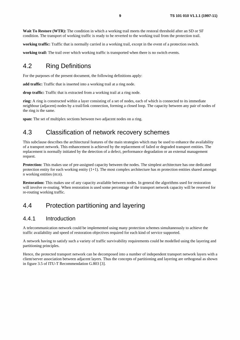


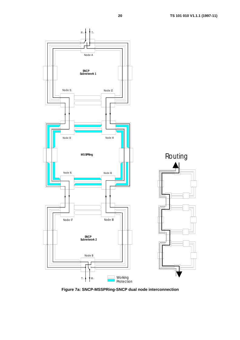


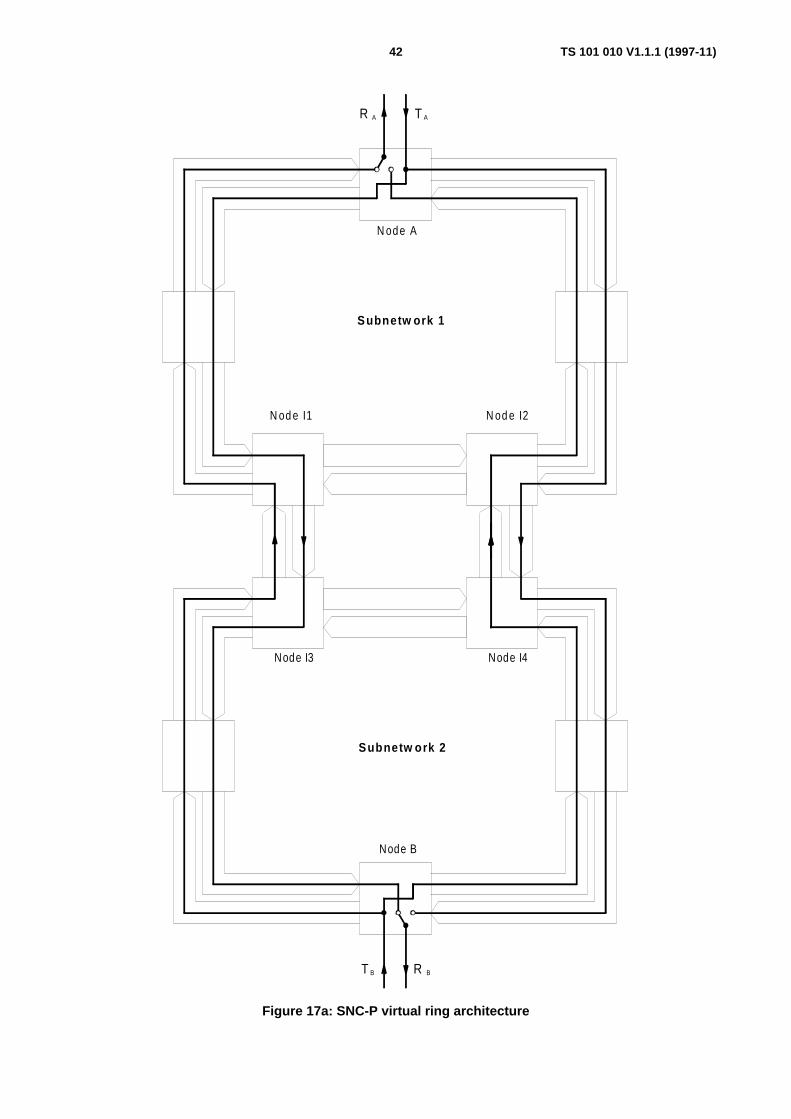


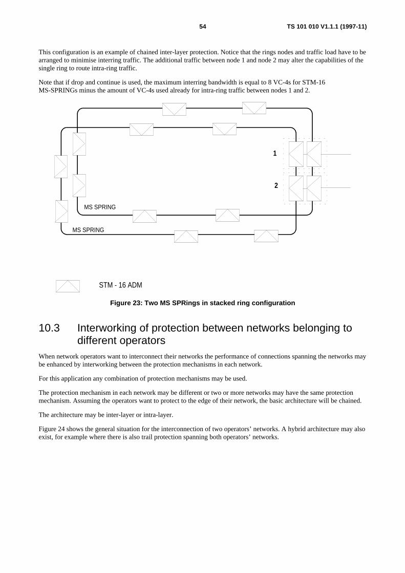


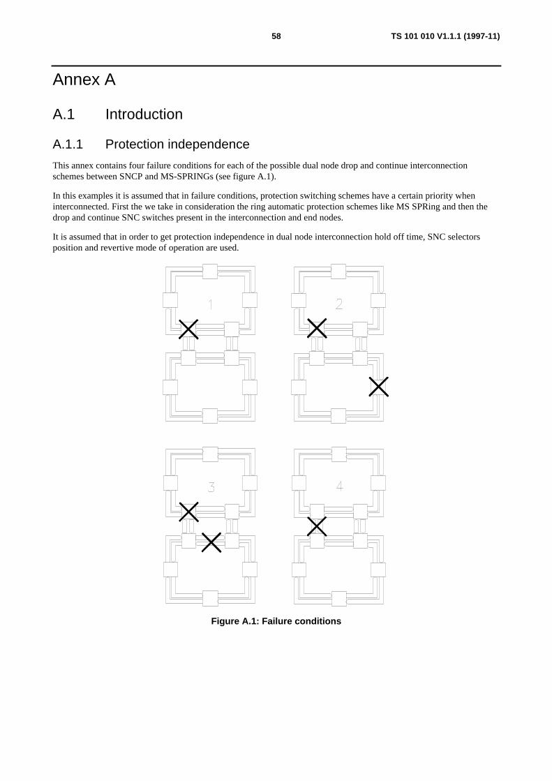

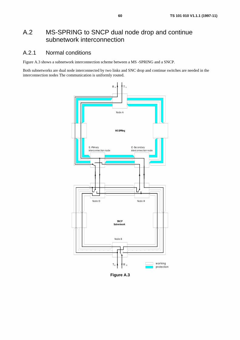


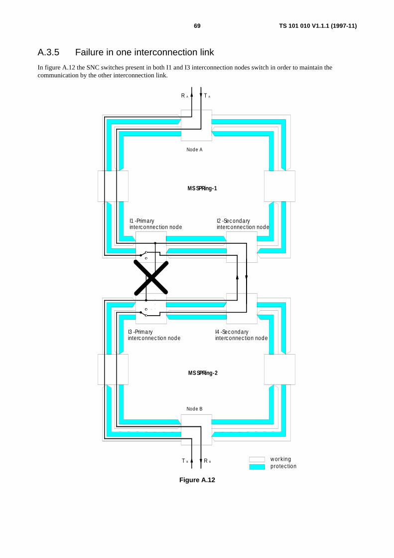
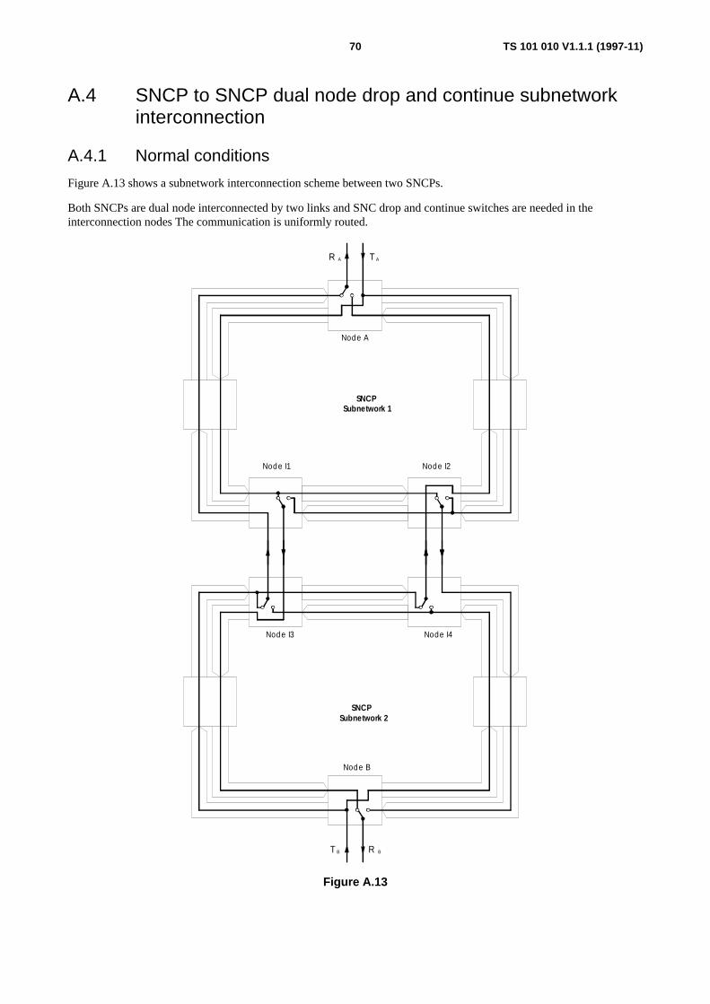


![TR 102 457 - V1.1.1 - Transmission and Multiplexing (TM ... · PDF fileStudy on the electromagnetic radiated field in fixed radio systems for environmental issues. ... (OET). [11]](https://static.documents.pub/doc/80x56/5abb91c67f8b9ab1118d2c69/tr-102-457-v111-transmission-and-multiplexing-tm-on-the-electromagnetic.jpg)


