ETSI TS 101 545-1 V1.2.1 (2014-04) Digital Video Broadcasting (DVB); Second Generation DVB Interactive Satellite System (DVB-RCS2); Part 1: Overview and System Level specification Technical Specification
Transcript
ETSI TS 101 545-1 V1.2.1 (2014-04)
Digital Video Broadcasting (DVB); Second Generation DVB Interactive Satellite System
(DVB-RCS2); Part 1: Overview and System Level specification
Technical Specification
ETSI
ETSI TS 101 545-1 V1.2.1 (2014-04)2
Reference RTS/JTC-DVB-324-1
Keywords DVB, interaction, satellite
ETSI
650 Route des Lucioles F-06921 Sophia Antipolis Cedex - FRANCE
Tel.: +33 4 92 94 42 00 Fax: +33 4 93 65 47 16
Siret N° 348 623 562 00017 - NAF 742 C
Association à but non lucratif enregistrée à la Sous-Préfecture de Grasse (06) N° 7803/88
Important notice
The present document can be downloaded from: http://www.etsi.org
The present document may be made available in electronic versions and/or in print. The content of any electronic and/or print versions of the present document shall not be modified without the prior written authorization of ETSI. In case of any
existing or perceived difference in contents between such versions and/or in print, the only prevailing document is the print of the Portable Document Format (PDF) version kept on a specific network drive within ETSI Secretariat.
Users of the present document should be aware that the document may be subject to revision or change of status. Information on the current status of this and other ETSI documents is available at
http://portal.etsi.org/tb/status/status.asp
If you find errors in the present document, please send your comment to one of the following services: http://portal.etsi.org/chaircor/ETSI_support.asp
Copyright Notification
No part may be reproduced or utilized in any form or by any means, electronic or mechanical, including photocopying and microfilm except as authorized by written permission of ETSI.
The content of the PDF version shall not be modified without the written authorization of ETSI. The copyright and the foregoing restriction extend to reproduction in all media.
Intellectual Property Rights ................................................................................................................................ 4
4 System definition ...................................................................................................................................... 9
4.1 General ............................................................................................................................................................... 9
4.2 System Roles .................................................................................................................................................... 12
4.5 System architecture .......................................................................................................................................... 13
4.11 Terminal capabilities and profiles .................................................................................................................... 14
4.12 System versioning ............................................................................................................................................ 16
4.12.1 Forward Link .............................................................................................................................................. 17
4.12.2 Return link .................................................................................................................................................. 18
4.12.3 Management and Control Planes ................................................................................................................ 18
4.12.4 RCST Synchronisation and Logon ............................................................................................................. 18
4.14 Evaluation and certification .............................................................................................................................. 21
History .............................................................................................................................................................. 22
ETSI
ETSI TS 101 545-1 V1.2.1 (2014-04)4
Intellectual Property Rights IPRs essential or potentially essential to the present document may have been declared to ETSI. The information pertaining to these essential IPRs, if any, is publicly available for ETSI members and non-members, and can be found in ETSI SR 000 314: "Intellectual Property Rights (IPRs); Essential, or potentially Essential, IPRs notified to ETSI in respect of ETSI standards", which is available from the ETSI Secretariat. Latest updates are available on the ETSI Web server (http://ipr.etsi.org).
Pursuant to the ETSI IPR Policy, no investigation, including IPR searches, has been carried out by ETSI. No guarantee can be given as to the existence of other IPRs not referenced in ETSI SR 000 314 (or the updates on the ETSI Web server) which are, or may be, or may become, essential to the present document.
Foreword This Technical Specification (TS) has been produced by Joint Technical Committee (JTC) Broadcast of the European Broadcasting Union (EBU), Comité Européen de Normalisation ELECtrotechnique (CENELEC) and the European Telecommunications Standards Institute (ETSI).
NOTE: The EBU/ETSI JTC Broadcast was established in 1990 to co-ordinate the drafting of standards in the specific field of broadcasting and related fields. Since 1995 the JTC Broadcast became a tripartite body by including in the Memorandum of Understanding also CENELEC, which is responsible for the standardization of radio and television receivers. The EBU is a professional association of broadcasting organizations whose work includes the co-ordination of its members' activities in the technical, legal, programme-making and programme-exchange domains. The EBU has active members in about 60 countries in the European broadcasting area; its headquarters is in Geneva.
European Broadcasting Union CH-1218 GRAND SACONNEX (Geneva) Switzerland Tel: +41 22 717 21 11 Fax: +41 22 717 24 81
The Digital Video Broadcasting Project (DVB) is an industry-led consortium of broadcasters, manufacturers, network operators, software developers, regulatory bodies, content owners and others committed to designing global standards for the delivery of digital television and data services. DVB fosters market driven solutions that meet the needs and economic circumstances of broadcast industry stakeholders and consumers. DVB standards cover all aspects of digital television from transmission through interfacing, conditional access and interactivity for digital video, audio and data. The consortium came together in 1993 to provide global standardisation, interoperability and future proof specifications.
The present document is part 1 of a multi-part deliverable covering the DVB Interactive Satellite System specification, as identified below:
TS 101 545-1: "Overview and System Level specification";
EN 301 545-2: "Lower Layers for Satellite standard";
Introduction EN 301 790 [1] defines the first generation of DVB-RCS which is a system providing an interaction channel for satellite distribution systems. Together with its guidelines (TR 101 790 [i.1]) the present document describes how such system can be built on the physical and MAC layers to provide an efficient way of turning a satellite broadcast TV into a full VSAT solution capable of transporting IP traffic in a satellite-only system.
Since the original definition of DVB-RCS systems, several versions of the standard were issued, describing the requirements for the implementation of a system providing an interaction channel for satellite distribution systems.
The sum of these specifications allowed to adapt the DVB-RCS systems to different market segments from small to large networks and from fixed to mobile terminals but it appears that the evolutions of the physical layer techniques and the stabilisation of IP standards now deserves deeper changes which can only be implemented in a consistent way via the definition of a second generation system.
The requirements in the present document have been introduced in order to provide the best possible interoperability between terminals and hubs, thus defining not only the lower layers of the system (up to layer 2) but also network functions as well as management and control capabilities.
As these requirements combined together may end up in a very complex terminal design, the present document also describes subsets of capabilities known as profiles that can be used together to address a given market segment.
ETSI
ETSI TS 101 545-1 V1.2.1 (2014-04)6
1 Scope The present document establishes the system specifications for the 2nd Generation Interactive DVB Satellite System (DVB-RCS2) and represents the first part of the multi-part specification of that system. It also gives links to the adequate sections into the detailed specification documents and explains how the features should be combined together to make a terminal compliant with different subsets of specifications mentioned here as profiles.
General terms and definitions are given in the present document which can be found also in the other parts of the DVB-RCS2 multi-part specification.
2 References References are either specific (identified by date of publication and/or edition number or version number) or non-specific. For specific references, only the cited version applies. For non-specific references, the latest version of the reference document (including any amendments) applies.
Referenced documents which are not found to be publicly available in the expected location might be found at http://docbox.etsi.org/Reference.
NOTE: While any hyperlinks included in this clause were valid at the time of publication ETSI cannot guarantee their long term validity.
2.1 Normative references The following referenced documents are necessary for the application of the present document.
[1] ETSI EN 301 790: "Digital Video Broadcasting (DVB); Interaction channel for satellite distribution systems".
[2] ETSI EN 301 545-2: "Digital Video Broadcasting (DVB); Second Generation DVB Interactive Satellite System (DVB-RCS2); Part 2: Lower Layers for Satellite standard".
[3] ETSI TS 101 545-3: "Digital Video Broadcasting (DVB); Second Generation DVB Interactive Satellite System (DVB-RCS2); Part 3: Higher Layers Satellite Specification".
[4] IETF RFC 3917: "Requirements for IP Flow Information Export (IPFIX)".
[5] IETF RFC 5474: "A Framework for Packet Selection and Reporting".
[6] IETF RFC 1213: "Management Information Base for Network Management of TCP/IP-based internets: MIB-II".
[7] IETF RFC 1901: "Introduction to Community-based SNMPv2".
[8] IETF RFC 1908: "Coexistence between Version 1 and Version 2 of the Internet-standard Network Management Framework".
[9] EUTELSAT, European Telecommunication Satellite Organization: "Digital Satellite Equipment Control (DiSEqC™) Bus specification".
[10] IETF RFC 5728: "The SatLabs Group DVB-RCS MIB".
2.2 Informative references The following referenced documents are not necessary for the application of the present document but they assist the user with regard to a particular subject area.
[i.1] ETSI TR 101 790: "Digital Video Broadcasting (DVB); Interaction channel for Satellite Distribution Systems; Guidelines for the use of EN 301 790".
3.1 Definitions For the purposes of the present document, the following terms and definitions apply:
control plane: communications that carry mainly signalling information
Layer 1 Mesh Overlay System: satellite interactive network that supplements the unidirectional satellite link from a TDM feeder to RCSTs and the unidirectional satellite link from RCSTs to an MF-TDMA gateway with two-way satellite links between the RCSTs
NOTE: In such systems, the NCC is connected to the RCST via the feeder and gateway.
Layer 1 Regenerative and Re-multiplexing System: satellite interactive network that relies on an on-board regenerative processor to demodulate upcoming MF-TDMA data from terminals and generate a TDM downlink signal with this data
NOTE: Such system looks like an RCS second generation system from the layer 1 RCSTs perspective.
management plane: communications that carry information to maintain the network and to perform operational functions
user plane: communications that carry user information
3.2 Symbols For the purposes of the present document, the following symbols apply:
α Roll-off factor Eb/N0 Ratio between the energy per information bit and single sided noise power spectral density Es/N0 Ratio between the energy per transmitted symbol and single sided noise power spectral density f0 Carrier frequency fN Nyquist frequency NR,max Number of replicas in a frame Nrand 12-bit random number used as a random seed value during CRDSA frame decoding Nslots Number of the slots in the frame Rs Symbol rate corresponding to the bilateral Nyquist bandwidth of the modulated signal
3.3 Abbreviations For the purposes of the present document, the following abbreviations apply:
ACM Adaptive Coding and Modulation BPSK Binary Phase Shift Keying CCM Constant Coding and Modulation CLI Command Line Interface CPM Continuous Phase Modulation (or Modulator) CRC Cyclic Redundancy Check CRC32 Cyclic Redundancy Check (32 bits) CRDSA Contention Resolution DSA CSC Common Signalling Channel DA Dedicated Access DAMA Demand Assignment Multiple Access DCP Dynamic Connectivity Protocol DHCP Dynamic Host Control Protocol DL DownLink DoS Denial-of-Services DSA Diversity Slotted Aloha DTP Digital Transparent Processor
ETSI
ETSI TS 101 545-1 V1.2.1 (2014-04)8
DVB-RCS Digital Video Broadcasting Return Channel by Satellite DVB-RCS2 Digital Video Broadcasting - Interactive Satellite System, Return Channel by Satellite second
generation DVB-S Digital Video Broadcasting by Satellite DVB-S2 Digital Video Broadcasting - Second generation framing structure, channel coding and modulation
systems for Broadcasting, Interactive Services, News Gathering and other broadband satellite applications
EIRP Equivalent Isotropic Radiated Power FEC Forward Error Correction FL Forward Link GS Generic Stream GSE Generic Stream Encapsulation GW GateWay HAIPE High Assurance Internet Protocol Encryptor HTTP Hyper Text Transfer Protocol ID IDentifier IN Interactive Network IPDR Internet Protocol Detail Record IPFIX Internet Protocol Flow Information Export IPv4 Internet Protocol, version 4 IPv6 Internet Protocol, version 6 ISI Input Stream Identifier LL Link Layer MAC Medium Access Control MF-TDMA Multiple-Frequency Time-Division Multiple Access MIB Management Information Base MPE Multi-Protocol Encapsulation MPLS Multiprotocol Label Switching MUC Multiplier Up Converter NCC Network Control Center NCR Network Control Reference NMC Network Management Center OBP On-Board Processor OSPF Open Shortest Path First OVN Operator Virtual Networks PEP Performance Enhancing Proxy PSAMP Packet Sampling PSK Phase Shift Keying QAM Quadrature Amplitude Modulation QoS Quality of Service RCS Return Channel Satellite RCST Return Channel Satellite Terminal RL Return Link RLE RL Encapsulation RSGW Regenerative Satellite GateWay SCADA Supervisory Control And Data Acquisition SDDP Software and Data Distribution Protocol SLA Service Level Agreement SNMP Simple Network Management Protocol SNO Satellite Network Operator SO Satellite Operator SVN Satellite Virtual Network SVNO Satellite Virtual Network Operator TCP Transmission Control Protocol TDM Time-Division Mode TLS Transport Layer Security TRANSEC TRANSmission SECurity TS MPEG2 Transport Stream TS-GW Transparent Satellite GateWay TX Transmit UL UpLink VSAT Very Small Aperture Terminal
ETSI
ETSI TS 101 545-1 V1.2.1 (2014-04)9
XML eXtensible Markup Language
4 System definition
4.1 General DVB-RCS2 is the standard conceived to provide a standardised broadband interactivity connection as an extension of the Digital Video Broadcasting Satellite systems. It defines the MAC and physical layer protocols of the air interface used between the satellite operator hub and the interactive user terminal as well as the network layer and the essential functions of the management and control planes of the terminal. It embraces the GSE and the DVB-S2 standards implemented in the commercial broadcasting environment, exploiting economics of scale.
In order to provide a real interoperability, the DVB-RCS2 specification describes Higher layers components adapted to satellite interactive systems. These component are parts of control and management planes and rely mainly on DVB and IETF standards or are derived from them.
A typical DVB-RCS2 Network will utilise a satellite with multi or single beam coverage. In most networks, the satellite carrying the forward link signal will also support the return link. The forward link carries signalling from the NCC and user traffic to RCSTs. The signalling from the Network Control Centre (NCC) to RCSTs that is required to operate the return link system is called "Forward Link Signalling". A Network Management Centre (NMC) provides overall management of the system elements and manages the Service Level Agreement (SLA) assigned to each RCST.
The following network topologies are addressed by the present document:
• Transparent star network system.
• Transparent star network system with contention access.
• Transparent mesh overlay network system.
• Regenerative mesh network system.
These network topologies can be summarized in two main reference architectures, shown in figures 1 and 2 hereafter, transparent and regenerative. The actors of both interactive systems are the same and can be observed in figure 3.
• Transparent system description shows both transparent star and mesh overlay network topologies and has the following components:
- Transparent satellite(s). One or more transparent satellites provide the link between terminals and the Hub, or among terminals for the transparent mesh system. Digital Transparent Processor (DTP) payloads can also give multi-beam connectivity.
- Hub/NCC. Performs the control (NCC), management (NMC) functions and interfaces user plane (traffic gateway) functions.
- Star terminals (RCSTs).The star transparent terminal complies with the requirements of the DVB-RCS2 standard, providing star connectivity, or mesh connectivity with a double satellite hop.
- Mesh overlay transparent terminals (RCSTs). The mesh overlay transparent terminals comply with the requirements of the DVB-RCS2 standard, providing star connectivity, mesh connectivity with a double satellite hop, and also mesh connectivity with a single satellite hop. The transparent mesh overlay terminal is more complex, it includes two or more demodulators adapted to DVB-S2 or RCST-TX waveforms as defined in DVB-RCS2.
ETSI
ETSI TS 101 545-1 V1.2.1 (2014-04)10
- Gateway RCST (GW-RCST). This a mesh RCST with SLA enforcement functions that takes the GW role. A GW-RCST provides mesh RCST users with access to terrestrial networks. There may be one GW-RCST giving service to a small number of terminals, or to a large number of terminals. Essentially, each comprise one RCST, plus an SLA Enforcer and an access router, but may also include VoIP telephony servers, traffic acceleration servers, and backhaul modules.
Figure 1: Main roles in a DVB-RCS2 transparent satellite interactive network
• Regenerative system DVB-RCS2 satellite interactive network which supports mesh topology:
- Regenerative satellite. Performs demodulation, demultiplexing, decoding (and possibly decapsulation) functions at the receiver side, on-board switching (at layer 2 or 3) for multi-beam systems, and the corresponding transmission functions after signal regeneration. The regenerative satellite payload embbeds an on board processor (OBP). This OBP behaves as a router, switch or multiplexer in the sky for mono or multi-beam systems. Its regeneration functions allow to use an uplink (UL) air interface format different from the downlink (DL) (by demodulation, decoding and new modulation and coding, and possibly des-encapsulation and new encapsulation functions). The air interface formats are DVB-RCS2 TX on the uplink and DVB-S2 on the downlink, depending on the topology scenario.
- Management Station. It provides the management (NMC) and control (NCC) plane functions to the satellite network users.
- Regenerative Satellite Gateway (GW-RCST). The GW-RCST is a satellite terminal that provides regenerative RCST users with access to terrestrial networks. There may be one GW-RCST giving service to a small number of terminals, or to large number of them. Essentially, a GW-RCST comprises one RCST, plus an SLA Enforcer and an access router, but may also include VoIP telephony servers, traffic acceleration servers, and backhaul modules.
- Regenerative mesh terminals. The regenerative mesh terminal complies with the requirements of the DVB-RCS2 standard, providing mesh connectivity with a single satellite hop. These RCSTs are identical in terms of hardware to the star transparent terminals, but their software includes additional functionalities to support dynamic mesh connectivity. These functions are not exclusive of making these terminals capable of being operated in star transparent or mesh overlay topologies.
ETSI
ETSI TS 101 545-1 V1.2.1 (2014-04)11
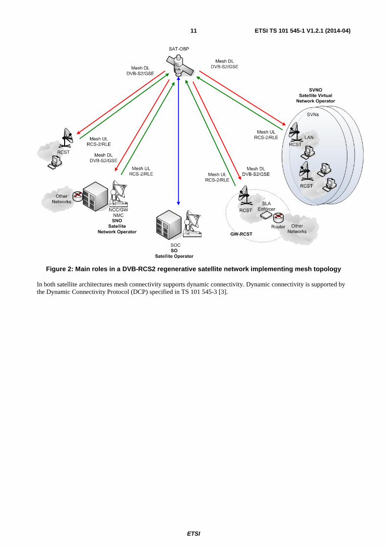
Figure 2: Main roles in a DVB-RCS2 regenerative satellite network implementing mesh topology
In both satellite architectures mesh connectivity supports dynamic connectivity. Dynamic connectivity is supported by the Dynamic Connectivity Protocol (DCP) specified in TS 101 545-3 [3].
ETSI
ETSI TS 101 545-1 V1.2.1 (2014-04)12
4.2 System Roles The system roles considered in a DVB-RCS2 interactive system are presented in the model shown in figure 3.
Figure 3: DVB-RCS2 actors and roles
1) Satellite Operator (SO), who manages the whole satellite, and sells capacity at transponder level to one or several SNOs.
2) Satellite Network Operators (SNO), are assigned one or more satellite transponders. Each SNO owns one or more NCC/NMC, and configures the time/frequency plan. Each SNO is responsible for one IN, corresponding to one DVB network (identified by the Network_ID), controlling their own capacity. The SNO may divide the interactive network into one or more Operator Virtual Networks (OVN). Each OVN is an independently managed higher layer network, and is managed by a SVNO. SNOs distribute their own physical and logical resources among OVNs. In the transparent architecture the SNO owns the TS-GW.
3) Satellite Virtual Network Operators (SVNO), are assigned one or more Operator Virtual Networks (OVN), each being given some physical and logical resources. An active RCST can only be a member of one OVN, This is assigned at logon to the DVB-RCS2 Network. Each OVN is assigned a pool of SVN numbers from which it can allocate SVN-MAC addresses. The SVN concept is used to logically divide the addressing space controlled by the operator. SVNOs sell connectivity services to their subscribers and for the regenerative architecture may also manage one or several RSGWs.
4) Subscriber (RCST), are the user stations, which they contract to the SVNOs.
5) End-user are the final actors enjoying the satellite services, connected to the RCST LAN interface.
4.3 Physical layer The physical layer of a DVB-RCS2 compliant terminal operating in a DVB-RCS2 system shall comply with the requirements defined in EN 301 545-2 [2]. Not all specifications need to be implemented depending on the terminal profile (see table 3) and also on supported options (see table 2). The specification of the elements which are optional or normative as well as the profiles and their related options are described in clause 4.11 Terminal capabilities and profiles.
ETSI
ETSI TS 101 545-1 V1.2.1 (2014-04)13
4.4 Access layer The access layer of a DVB-RCS2 compliant terminal operating in a DVB-RCS2 system shall comply with the requirements defined in EN 301 545-2 [2]. Not all specifications need to be implemented depending on the terminal profile (see table 3) and also on supported options (see table 2). The specification of the elements which are optional or normative as well as the profiles and their related options are described in clause 4.11 Terminal capabilities and profiles.
4.5 System architecture The architecture of a DVB-RCS2 compliant terminal shall be compatible with the system architecture specified in TS 101 545-3 [3].
4.6 Network layer The network layer of a DVB-RCS2 compliant terminal shall follow the requirements indicated in TS 101 545-3 [3]. Some of these specifications are optional and may be required to meet some of the defined terminals profiles, refer to clause 4.11 Terminal capabilities and profiles of the present document for the details of these specifications.
4.7 Management functions The management functions of a DVB-RCS2 compliant terminal shall follow the requirements indicated in TS 101 545-3 [3]. Some of these specifications are optional and may be required to meet some of the defined terminals profiles, refer to clause 4.11 Terminal capabilities and profiles of the present document for the details of these specifications.
4.8 Traffic interception The traffic interception functions of a DVB-RCS2 compliant terminal shall follow the requirements indicated in TS 101 545-3 [3]. These specifications are optional and are not required for any profile.
4.9 Terminal installation functions The terminal installation functions of a DVB-RCS2 compliant terminal shall follow the requirements indicated in TS 101 545-3 [3]. The potential waveforms to be used for the installation procedure are described in EN 301 545-2 [2]. The motor control commands shall follow DiSEqCTM [9] specification. Implementation of these control commands are optional as indicated in table 2 and are not required for any profile.
4.10 Terminal future configurations [informational] Terminals capabilities defined in EN 301 545-2 [2] and TS 101 545-3 [3] cover essential use of the DVB-RCS2 systems. This informational clause provides some insight of future usages of the system which are foreseen in the scope of improved link efficiency or specific applications support and will be defined in new versions of the current set of specifications.
ETSI
ETSI TS 101 545-1 V1.2.1 (2014-04)14
Table 1: Terminal future configurations options
Terminal feature Comment PHYSICAL LAYER SC-FDMA support on the return link Improvement of the return link efficiency
Direct Sequence spread spectrum on the forward link Provides improved downlink reception for small aperture terminals
MAC LAYER
Network LAYER
GSM/ WiMax backhauling Requires further investigation to assess which optimisations are required
IP Gateway implementation To be further defined Management LAYER
4.11 Terminal capabilities and profiles Systems implementing DVB-RCS2 standard are not mandated to implement all features defined in the lower layers and higher layer satellite specifications documents. In order to better match DVB-RCS2 systems with their potential uses, a set of terminal profiles and features is defined in this clause.
Terminal optional features are defined as a set of capabilities that a terminal can implement or not depending on its design. Implementation of these features depends on the manufacturer decision and represents a competitive differentiation with respect to other designs. Normative features shall be implemented by all DVB-RCS2 terminals.
The fact that these features are implemented or not does not prevent the terminal to be interoperable with hubs as the hub should be aware of the implementation of these features via signalling.
In the particular case of mobile DVB-RCS2 terminals, some capabilities may be implemented to improve their capacity or their suitability when used in a mobile environment. Actually, no specific feature is mandated to support mobility as DVB-RCS2 terminals implementing no option can be mobile. Anyway, some features like hand-over management or spread spectrum support will improve significantly the exploitation of terminals in a mobile system by allowing smooth transitions between coverages or small aperture terminals.
This does not create a specific terminal profile (see table 3) as any terminal can be mobile and no specific feature is linked to mobility either. Eventually, mobility implementation for a DVB-RCS2 terminal is a feature that is tied to its supporting platform and antenna system which is not covered by the scope of the present document.
ETSI
ETSI TS 101 545-1 V1.2.1 (2014-04)15
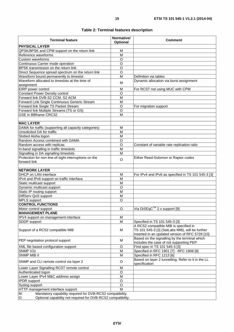
Table 2: Terminal features description
Terminal feature Normative/ Optional Comment
PHYSICAL LAYER QPSK/8PSK and CPM support on the return link M Reference waveforms M Custom waveforms O Continuous Carrier mode operation O BPSK transmission on the return link O Direct Sequence spread spectrum on the return link O Waveform bound permanently to timeslot M Definition via tables Waveform allocated to timeslots at the time of assignment
M Dynamic allocation via burst assignment
EIRP power control M For RCST not using MUC with CPM Constant Power Density control O Forward link DVB-S2 CCM, S2 ACM M Forward Link Single Continuous Generic Stream M Forward link Single TS Packet Stream O For migration support Forward link Multiple Streams (TS or GS) O GSE in BBframe CRC32 M MAC LAYER DAMA for traffic (supporting all capacity categories) M Unsolicited DA for traffic M Slotted Aloha logon M Random Access combined with DAMA O Random access with replicas O Constant of variable rate replication ratio In-band signalling in traffic timeslots M Signalling in DA signalling timeslots M Protection for non line-of-sight interruptions on the forward link O Either Reed-Solomon or Raptor codes
NETWORK LAYER DHCP on LAN interface M For IPv4 and IPv6 as specified in TS 101 545-3 [3] IPv4 and IPv6 support on traffic interface M Static multicast support M Dynamic multicast support O Static IP routing support M DiffServ QoS support M MPLS support O CONTROL FUNCTIONS Motor control support O Via DiSEqCTM 2.x support [9] MANAGEMENT PLANE IPV4 support on management interface M SDDP support M Specified in TS 101 545-3 [3]
Support of a RCS2 compatible MIB M A RCS2 compatible MIB is specified in TS 101 545-3 [3] (SatLabs MIB), will be further inserted in an updated version of RFC 5728 [10]
PEP negotiation protocol support M Based on the signalling by the terminal which includes the case of not supporting PEP
XML file based configuration support O Find spec in TS 101 545-3 [3] SNMP V2c M Specified in RFC 1901 [7] - RFC 1908 [8] SNMP MIB II M Specified in RFC 1213 [6]
SNMP and CLI remote control via layer 2 O Based on layer 2 tunnelling. Refer to it in the LL specification
Lower Layer Signalling RCST remote control M Authenticated logon O Lower Layer IPv4 M&C address assign M IPDR support O Syslog support O HTTP management interface support M M: Mandatory capability required for DVB-RCS2 compatibility. O: Optional capability not required for DVB-RCS2 compatibility.
ETSI
ETSI TS 101 545-1 V1.2.1 (2014-04)16
In addition to the terminals features, a set of profiles is defined. Capabilities used as keys for profiling allow system designers to identify a set of minimum specifications for a terminal that declares its compliance to a given profile. A terminal can comply with several profiles and implement features or have performances above those defined in table 3. The requirements in this clause should be understood as minimum capabilities for a terminal to be declared as compliant to a usage profile.
Table 3: Terminal profiles description
Co
nsu
mer
Mu
lti-d
wellin
g
Co
rpo
rate
SC
AD
A
Backh
aul
Institu
tion
al
PHYSICAL LAYER 16 QAM return link modulation O O M O M M 32APSK Forward Link modulation O O O O M M Essential waveform flexibility O O M O M M Fast carrier switching O O M O M M Lowest carrier switching class 1 1 2 1 2 2 MAC LAYER Minimum number of supported traffic SVN 1 4 4 1 4 4 Minimum number of layer 2 traffic classes (request classes and allocation channels)
3 3 7 3 3 7
Slotted Aloha traffic O O O M O O TRANSEC hooks support O O O O O M NETWORK LAYER Minimum number of simultaneous traffic multicast streams reception 16 64 64 16 16 64 Dynamic IP routing via OSPF support O M M O M M Firewall capability O O M M O M Multicast forwarding on the return link O O O O O M MANAGEMENT LAYER SNMP v3 support (*) O M M O M M Multi SVNO support O M O O O O M: Mandatory capability required for this profile. O: Optional capability not required for this profile. (*) SNMP V2c is required as a minimum for all terminals profiles while SNMP V3 should be
normative unless specified optional.
4.12 System versioning The scope of version 2 designated as the DVB-RCS2standard is extended significantly compared to that of version 1 as defined in EN 301 790 [1] and designated as DVB-RCS. In particular, DVB-RCS2 contains mandatory provisions for the management and control planes. Furthermore, in order to enhance efficiency, this version has introduced a significant number of non-backwards-compatible changes to certain mandatory provisions that are covered in both versions. This applies, inter alia, to the encapsulation, modulation and coding of the return link transmissions, as well as to the carriage of signalling in the forward link.
These changes have been introduced in a manner that facilitates a smooth migration from Version 1 to Version 2, with minimal operational impact. It is envisaged that such a migration may take place over an extended period of time. In particular, already-deployed RCST's operating according to Version 1 may not be software-upgradeable to Version 2, so a system operator may choose to operate according to Version 2 only on newly-deployed and replaced terminals. Accordingly, Version 1 may only be phased out as existing terminals reach the end of their operational life. It is therefore very important that the two versions can co-exist within a system and share the resources in an efficient manner.
Clause 4.12.1 describes the envisaged scenarios and associated normative provisions for forward links; clause 4.12.2 presents the corresponding provisions for return and mesh links. Some considerations for Management and Control Planes, Synchronisation and Logon are presented in clauses 4.12.3 and 4.12.4.
ETSI
ETSI TS 101 545-1 V1.2.1 (2014-04)17
4.12.1 Forward Link
Migration scenarios for the forward link depend on the starting point. The forward link in DVB-RCS Version 2 is intended to use the Generic Stream Encapsulation protocol exclusively, including for transport of signalling. In DVB-RCS (EN 301 790 [1]) specification, one or more Transport Streams are used to carry traffic and signalling.
The multi-input-stream capabilities of DVB-S2 can be exploited to allow sharing of a physical forward link carrier among RCST populations operating according to both versions. This greatly facilitates migration, in particular for systems employing a forward link that occupies a complete transponder. Avoiding multi-carrier operation eliminates the need to back off the transponder during the migration.
Carrier sharing is not possible if the original system uses DVB-S or include RCST's that support only the minimum functionality mandated for DVB-S2 (CCM with single input transport stream).
As a special provision to facilitate migration, Version 2 RCST's may be able to extract forward link traffic and signalling from a Transport Stream. This optional feature provides tools that facilitate the migration process. This feature ameliorates restrictions dictated by fundamental differences between forward link carriers, in particular between DVB-S and DVB-S2. By using this optional feature, it is possible to design hybrid migration scenarios for the overall system, in which the forward and return links are migrated separately. For example, a DVB-RCS forward link can be used to transport traffic and signalling to both DVB-RCS and DVB-RCS2 capable RCST's. The latter may in turn use a DVB-RCS2 return link.
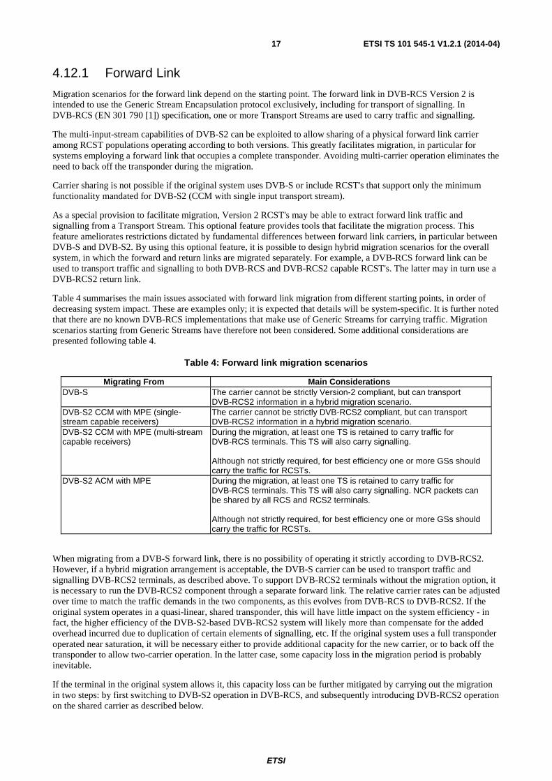
Table 4 summarises the main issues associated with forward link migration from different starting points, in order of decreasing system impact. These are examples only; it is expected that details will be system-specific. It is further noted that there are no known DVB-RCS implementations that make use of Generic Streams for carrying traffic. Migration scenarios starting from Generic Streams have therefore not been considered. Some additional considerations are presented following table 4.
Table 4: Forward link migration scenarios
Migrating From Main Considerations DVB-S The carrier cannot be strictly Version-2 compliant, but can transport
DVB-RCS2 information in a hybrid migration scenario. DVB-S2 CCM with MPE (single-stream capable receivers)
The carrier cannot be strictly DVB-RCS2 compliant, but can transport DVB-RCS2 information in a hybrid migration scenario.
DVB-S2 CCM with MPE (multi-stream capable receivers)
During the migration, at least one TS is retained to carry traffic for DVB-RCS terminals. This TS will also carry signalling. Although not strictly required, for best efficiency one or more GSs should carry the traffic for RCSTs.
DVB-S2 ACM with MPE During the migration, at least one TS is retained to carry traffic for DVB-RCS terminals. This TS will also carry signalling. NCR packets can be shared by all RCS and RCS2 terminals. Although not strictly required, for best efficiency one or more GSs should carry the traffic for RCSTs.
When migrating from a DVB-S forward link, there is no possibility of operating it strictly according to DVB-RCS2. However, if a hybrid migration arrangement is acceptable, the DVB-S carrier can be used to transport traffic and signalling DVB-RCS2 terminals, as described above. To support DVB-RCS2 terminals without the migration option, it is necessary to run the DVB-RCS2 component through a separate forward link. The relative carrier rates can be adjusted over time to match the traffic demands in the two components, as this evolves from DVB-RCS to DVB-RCS2. If the original system operates in a quasi-linear, shared transponder, this will have little impact on the system efficiency - in fact, the higher efficiency of the DVB-S2-based DVB-RCS2 system will likely more than compensate for the added overhead incurred due to duplication of certain elements of signalling, etc. If the original system uses a full transponder operated near saturation, it will be necessary either to provide additional capacity for the new carrier, or to back off the transponder to allow two-carrier operation. In the latter case, some capacity loss in the migration period is probably inevitable.
If the terminal in the original system allows it, this capacity loss can be further mitigated by carrying out the migration in two steps: by first switching to DVB-S2 operation in DVB-RCS, and subsequently introducing DVB-RCS2 operation on the shared carrier as described below.
ETSI
ETSI TS 101 545-1 V1.2.1 (2014-04)18
A similar situation occurs if the original system uses DVB-S2 but includes DVB-RCS terminals that implement only the bare minimum required by the DVB-S2 standard (CCM with single transport stream). In this case, the multi-stream capabilities of DVB-S2 cannot be exploited, so it is again necessary either to use separate forward link carriers or to transport DVB-RCS2 traffic and signalling on the DVB-RCS carrier in a hybrid migration arrangement.
Apart from this case, the migration path from a DVB-S2 based DVB-RCS system depends on how the original system is operated; in particular on whether the original system is CCM or ACM. This distinction arises from the fact that DVB-RCS carries the NCR synchronisation information in different ways, depending on the mode. The method used in DVB-RCS2 is analogous to that used in DVB-RCS with ACM, while that used with CCM in DVB-RCS is substantially different. When migrating from a DVB-RCS CCM system, it may therefore be necessary to carry two separate sets of NCR packets: One transmitted according to the CCM method, one according to the ACM/DVB-RCS2 method. This depends on whether the backwards compatibility of the DVB-RCS2 terminals extends to supporting the CCM NCR method.
One or more Transport Streams have to be retained during the migration to carry traffic to DVB-RCS terminals as well as to carry some or all signalling. For best efficiency, one or more GSs should be added to the carrier to handle traffic to DVB-RCS2 terminals.
In all DVB-S2 migration scenarios, input streams are separated by ISI value and no explicit re-configuration is required at the DVB-S2 level in order to apportion capacity among the two terminal populations.
4.12.2 Return link
While the basic MF-TDMA nature of the return link has been retained from DVB-RCS to DVB-RCS2, incompatible changes have been introduced to the encapsulation (variable-payload RLE vs. fixed-payload ATM/MPEG), FEC coding (16-state vs. 8-state turbo code), burst formatting (distributed pilots vs. preamble-only), modulation (extension to 8PSK and 16QAM) and dynamic operation (rapid changes to the time slot parameters). It is envisaged that these changes will necessitate corresponding changes to the resource management functions. As a result of this, the recommended resource sharing method in the return link during migration from DVB-RCS to DVB-RCS2 is to exploit the multi-carrier nature of the transmission scheme, configuring separate sets of carriers with appropriate characteristics and capacity for the two terminals populations. This configuration will evolve over time, as the usage of DVB-RCS decreases and that of DVB-RCS2 increases. In all but the smallest systems, this will provide a relatively fine granularity for the capacity sharing. The partitioning will however be quasi-static, so some loss of capacity can be encountered. This loss is however at least partly compensated by the better power/bandwidth efficiency of Version 2, and can be further mitigated by the special logon provisions described below.
It is conceivable that individual carriers can be shared between DVB-RCS and DVB-RCS2, by a judicious design of the frame formats that create non-overlapping resources for the two elements (e.g. letting the first half of each superframe be DVB-RCS and the second half DVB-RCS2). This may be of interest particularly for very small systems. There are no special normative provisions to support this type of operation; implementation is left to individual vendors and system operators.
4.12.3 Management and Control Planes
Management and control plane functions above the MAC layer are outside the scope of DVB-RCS, with systems relying largely on vendor-specific provisions. By definition, there is therefore no interoperable migration path to DVB-RCS2 for these aspects.
4.12.4 RCST Synchronisation and Logon
Both versions of the standard have defined ways of locating the forward link carrier and the (TS or GS) stream carrying the signalling; based on the population_id and other fundamental parameters configured in each terminal. As a minimum, any terminal attempting to enter the system will therefore be able to locate the appropriate resources unambiguously and will therefore also be able to attempt logon in the appropriate partition of the return link resource.
Furthermore, as a migration aid, DVB-RCS2 includes an optional, backwards-compatible variant of the logon (CSC) burst from DVB-RCS. This variant allows the terminals to indicate its DVB-RCS2 capabilities as well as whether it can operate fully in accordance with DVB-RCS. This feature allows the NCC to make the decision about the version to be used for any session at logon time, rather than using a pre-determined configuration. This can be used for example for load balancing, hence minimising the impact of the resource partitioning between DVB-RCS and DVB-RCS2.
ETSI
ETSI TS 101 545-1 V1.2.1 (2014-04)19
4.13 Security aspects This clause addresses system security issues - concerned with protection of the network itself - as well as lawful interception of traffic.
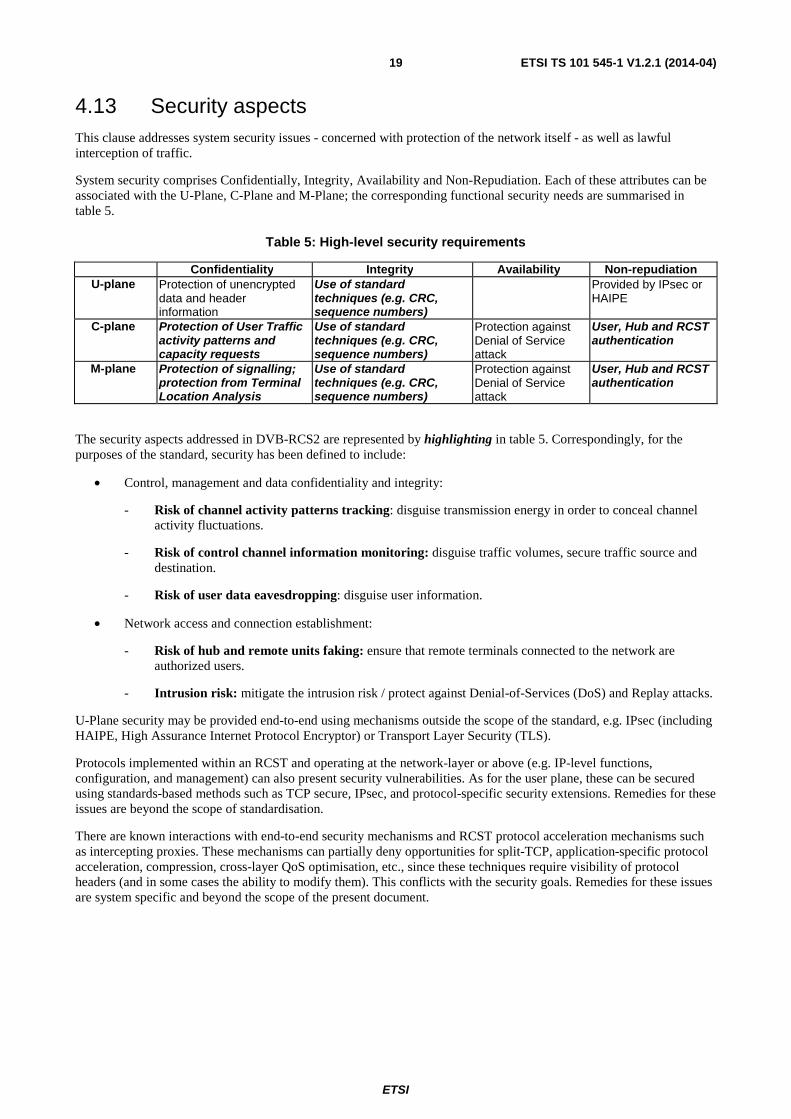
System security comprises Confidentially, Integrity, Availability and Non-Repudiation. Each of these attributes can be associated with the U-Plane, C-Plane and M-Plane; the corresponding functional security needs are summarised in table 5.
Table 5: High-level security requirements
Confidentiality Integrity Availability Non-repudiation U-plane Protection of unencrypted
data and header information
Use of standard techniques (e.g. CRC, sequence numbers)
Provided by IPsec or HAIPE
C-plane Protection of User Traffic activity patterns and capacity requests
Use of standard techniques (e.g. CRC, sequence numbers)
Protection against Denial of Service attack
User, Hub and RCST authentication
M-plane Protection of signalling; protection from Terminal Location Analysis
Use of standard techniques (e.g. CRC, sequence numbers)
Protection against Denial of Service attack
User, Hub and RCST authentication
The security aspects addressed in DVB-RCS2 are represented by highlighting in table 5. Correspondingly, for the purposes of the standard, security has been defined to include:
• Control, management and data confidentiality and integrity:
- Risk of channel activity patterns tracking: disguise transmission energy in order to conceal channel activity fluctuations.
- Risk of control channel information monitoring: disguise traffic volumes, secure traffic source and destination.
- Risk of user data eavesdropping: disguise user information.
• Network access and connection establishment:
- Risk of hub and remote units faking: ensure that remote terminals connected to the network are authorized users.
- Intrusion risk: mitigate the intrusion risk / protect against Denial-of-Services (DoS) and Replay attacks.
U-Plane security may be provided end-to-end using mechanisms outside the scope of the standard, e.g. IPsec (including HAIPE, High Assurance Internet Protocol Encryptor) or Transport Layer Security (TLS).
Protocols implemented within an RCST and operating at the network-layer or above (e.g. IP-level functions, configuration, and management) can also present security vulnerabilities. As for the user plane, these can be secured using standards-based methods such as TCP secure, IPsec, and protocol-specific security extensions. Remedies for these issues are beyond the scope of standardisation.
There are known interactions with end-to-end security mechanisms and RCST protocol acceleration mechanisms such as intercepting proxies. These mechanisms can partially deny opportunities for split-TCP, application-specific protocol acceleration, compression, cross-layer QoS optimisation, etc., since these techniques require visibility of protocol headers (and in some cases the ability to modify them). This conflicts with the security goals. Remedies for these issues are system specific and beyond the scope of the present document.
ETSI
ETSI TS 101 545-1 V1.2.1 (2014-04)20
4.13.1 Transmission Security (TRANSEC)
The countermeasure techniques commonly used for mitigating security risks in the management and control planes are known as TRANSEC. The techniques foreseen in the standard include link layer encryption including its associated key management, authentication and traffic activity concealment/obfuscation. The normative document provides features for transport of the information associated with these countermeasures, including for example encryption key exchange messages, initialisation vectors and authentication handshaking. Given that specific requirements and preferred techniques vary substantially between users, details of the techniques and associated signalling are outside the scope of the normative provisions. A number of implementations are described in the guidelines document.
TRANSEC encryption can be applied in the link layer to both Forward Link (FL) and Return Link (RL) of a DVB-RCS2 network, to all data packets (payloads and headers) and to all signalling, with a small number of exceptions dictated by physical transport considerations. In mesh regenerative systems some headers may be sent as clear text to allow on-board switching / routing. Link layer encryption is foreseen to be based on approved algorithms, used in approved modes of operations. For military and governmental applications the encryption algorithms and the operation modes will normally be military approved.
On the forward link, the traffic activity can be concealed/obfuscated by transmitting dummy or "chaff" packets in broadcast mode. On the return link, the traffic activity can be concealed / obfuscated by transmitting dummy bursts. The policies for slot allocation for dummy bursts are system specific.
In order to ensure that transport of TRANSEC-specific information can take place in an interoperable manner, the following mandatory protocol types are defined for GSE in the forward link and RLE in return/mesh links:
• TRANSEC_Chaff: This mandatory protocol type indicates that the packet contains meaningless "chaff" or "dummy" data. The contents of such packets shall be discarded by the receiver.
• TRANSEC_Certificate: This mandatory protocol type indicates that the packet contains certificate exchange information for control of a TRANSEC function. The packet contents are implementation-specific. Such packets can be discarded by receivers not implementing TRANSEC.
The corresponding protocol type values are assigned by the IETF.
4.13.2 fLawful Interception
A DVB-RCS2 Network may need to consider the requirements for lawful interception of user traffic. These requirements vary depending on location and local legislation.
For star networks, lawful interception functionality may be provided at the hub.
In mesh networks, the opportunities for lawful interception are system dependent. OBP-based mesh networks typically assemble all transmissions into a single TDM per beam, so interception can be achieved by the same means as for star networks, by employing a single receiving station in each beam. This function will normally be available at the NCC in any case.
Some transparent mesh networks also have a reception function at the hub, where all traffic can be monitored. Although usually intended for extraction of signalling, this function can also be used for lawful interception.
In those transparent mesh networks where no central traffic monitoring is available as part of the normal system operation, it may be necessary to install dedicated monitoring facilities in each beam.
A number of existing techniques may be used for interception of traffic in IP networks, including DVB-ISS networks. These include for example IPFIX (Internet Protocol Flow Information Export) (RFC 3917 [4]) and PSAMP (Packet Sampling) (RFC 5474 [5]). The former is an IETF standard for common export of Internet Protocol flow information from routers, probes, and other devices. It is used by mediation systems, accounting/billing systems, and network management systems to facilitate services such as measurement, accounting, and billing. The PSAMP protocol allows packets to be selected from a stream according to a set of standardised selectors, to form a stream of reports on the selected packets, and to export the reports to a collector using the IPFIX framework. The details of these techniques, and the manner in which they are applied, are outside the scope of the standard.
ETSI
ETSI TS 101 545-1 V1.2.1 (2014-04)21
4.14 Evaluation and certification This clause is provisioned for future versions of the present document may refer to evaluation and certification methods for RCSTs terminals and systems.


![TS 102 592-2 - V1.2.1 - Digital Video Broadcasting (DVB ... · [7] ETSI TS 102 832: "Digital Video Broadcasti ng (DVB); IP Datacast over DVB-H: Notification Framework". 2.2 Informative](https://static.documents.pub/doc/80x56/5e111fb69cd85e4f0b049c76/ts-102-592-2-v121-digital-video-broadcasting-dvb-7-etsi-ts-102-832.jpg)

