122
ETSI TS 101 761-4 V1.1.1 (2000-06) Technical Specification Broadband Radio Access Networks (BRAN); HIPERLAN Type 2; Data Link Control (DLC) Layer; Part 4: Extension for Home Environment
ETSI TS 101 761-4 V1.1.1 (2000-06)Technical Specification
Broadband Radio Access Networks (BRAN);HIPERLAN Type 2;
Data Link Control (DLC) Layer;Part 4: Extension for Home Environment

ETSI
ETSI TS 101 761-4 V1.1.1 (2000-06)2
ReferenceDTS/BRAN-0020004-4
Keywordsaccess, broadband, hiperlan, IP, layer 2, MAC,
radio
ETSI
650 Route des LuciolesF-06921 Sophia Antipolis Cedex - FRANCE
Tel.: +33 4 92 94 42 00 Fax: +33 4 93 65 47 16
Siret N° 348 623 562 00017 - NAF 742 CAssociation à but non lucratif enregistrée à laSous-Préfecture de Grasse (06) N° 7803/88
Important notice
Individual copies of the present document can be downloaded from:http://www.etsi.org
The present document may be made available in more than one electronic version or in print. In any case of existing orperceived difference in contents between such versions, the reference version is the Portable Document Format (PDF).
In case of dispute, the reference shall be the printing on ETSI printers of the PDF version kept on a specific networkdrive within ETSI Secretariat.
Users of the present document should be aware that the document may be subject to revision or change of status.Information on the current status of this and other ETSI documents is available at http://www.etsi.org/tb/status/
If you find errors in the present document, send your comment to:[email protected]
Copyright Notification
No part may be reproduced except as authorized by written permission.The copyright and the foregoing restriction extend to reproduction in all media.
© European Telecommunications Standards Institute 2000.All rights reserved.
ETSI
ETSI TS 101 761-4 V1.1.1 (2000-06)3
Contents
Intellectual Property Rights................................................................................................................................6
Foreword ............................................................................................................................................................6
Introduction ........................................................................................................................................................6
1 Scope ........................................................................................................................................................7
2 References ................................................................................................................................................7
3 Definitions, symbols and abbreviations ...................................................................................................73.1 Definitions ..........................................................................................................................................................73.2 Symbols ..............................................................................................................................................................93.3 Abbreviations .....................................................................................................................................................9
4 Overview ................................................................................................................................................114.1 H/2 Home Network Architecture......................................................................................................................114.1.1 The single subnet model .............................................................................................................................114.1.2 The multiple subnets model ........................................................................................................................124.2 Service Types to be supported..........................................................................................................................124.3 Types of Devices supported .............................................................................................................................13
5 DM transmission and reception functions .............................................................................................135.1 Logical channels and their characteristics ........................................................................................................135.2 Transport channels and their characteristics.....................................................................................................145.3 Mapping between logical and transport channels .............................................................................................145.4 Mapping between MAC frame and PHY frame ...............................................................................................145.5 DLC Addressing for Home Environment .........................................................................................................145.6 Use of DiL logical channels .............................................................................................................................155.6.1 Overview of the MAC frame ......................................................................................................................155.6.2 Resource request and resource grant for direct link....................................................................................165.6.3 DiL LCCH for ARQ ...................................................................................................................................165.6.4 DiL DCCH for RLC....................................................................................................................................165.6.5 DiL RBCH for RLC....................................................................................................................................165.7 MAC protocol for DM .....................................................................................................................................165.8 EC protocol for DM .........................................................................................................................................175.8.1 General........................................................................................................................................................175.8.2 Error Control (EC) protocol for the acknowledged mode...........................................................................195.8.2.1 Handling of Dynamic ARQ bandwidth allocation for DM....................................................................195.8.2.2 Setting of the ARB in the RR for DiL ...................................................................................................195.8.2.3 Receiver actions in case of insufficient ARQ feedback resources (informative)...................................195.8.2.4 Transmitter actions in case of insufficient ARQ feedback resources (informative) ..............................205.8.2.5 Scheduling of sufficient ARQ feedback resources (informative) ..........................................................205.8.3 EC protocol for the repetition and unacknowledged mode.........................................................................205.8.4 EC protocol for the FEC mode ...................................................................................................................205.8.4.1 Principles...............................................................................................................................................205.8.4.2 UDCH message format .........................................................................................................................215.8.4.3 RS word generation...............................................................................................................................225.8.4.4 Dummy LCH PDU generation ..............................................................................................................235.8.4.5 Interleaver and deinterleaver .................................................................................................................245.8.4.6 Interleaver/deinterleaver memories initialization ..................................................................................245.8.4.7 Connection termination .........................................................................................................................255.9 Broadcast Transmission....................................................................................................................................255.10 Encryption ........................................................................................................................................................26
6 Services supported by the Radio Link Control sublayer........................................................................276.1 General .............................................................................................................................................................276.1.1 Basic RLC Functions applied .....................................................................................................................286.1.1.1 DLC User Connection Control..............................................................................................................286.1.1.2 Radio Resource Control ........................................................................................................................28

ETSI
ETSI TS 101 761-4 V1.1.1 (2000-06)4
6.1.2 Changed RLC Functions.............................................................................................................................286.1.2.1 Association Control Function................................................................................................................286.1.2.2 Radio Resource Control ........................................................................................................................296.1.3 Changed RLC Messages, Parameter Settings .............................................................................................296.1.3.1 Association Control Function................................................................................................................296.1.3.2 DLC User Connection Control..............................................................................................................296.1.4 New RLC Functionality ..............................................................................................................................306.2 Terminal association for multiple convergence layers......................................................................................306.3 Link Adaptation in Direct Link Phase ..............................................................................................................306.4 Power Control in Direct Link Phase.................................................................................................................316.4.1 Direct Link unicast power control...............................................................................................................316.4.1.1 Connectivity Check ...............................................................................................................................326.4.1.2 Power Update........................................................................................................................................346.4.2 Direct Link Multicast/Broadcast Power Control.........................................................................................356.5 Link Quality Calibration for DM operation......................................................................................................366.5.1 Principles of Calibration .............................................................................................................................366.5.2 Measurement Phase ....................................................................................................................................376.5.2.1 Calibration-Measurement Trigger .........................................................................................................376.5.2.2 Calibration Measurement ......................................................................................................................386.5.3 Reporting Phase ..........................................................................................................................................386.5.3.1 Calibration-Report Trigger:...................................................................................................................396.5.3.2 Calibration Report:................................................................................................................................396.5.4 Link Quality Map of the Network...............................................................................................................416.6 DLC User Connection Control .........................................................................................................................446.6.1 Fixed slot allocation for DM.......................................................................................................................446.6.2 Multicast in DiL phase................................................................................................................................446.6.2.1 General ..................................................................................................................................................446.6.2.2 DiL MULTICAST SETUP, WT-initiated.............................................................................................466.6.2.3 DiL MULTICAST SETUP for a new joining WT................................................................................496.6.2.4 DiL MULTICAST SETUP, CC initiated ..............................................................................................496.6.2.5 MODIFY MULTICAST .......................................................................................................................506.6.2.6 RELEASE MULTICAST .....................................................................................................................526.7 Dynamic CC Selection .....................................................................................................................................546.7.1 Principle......................................................................................................................................................546.7.2 Initial Scanning Process..............................................................................................................................546.7.3 Definitions ..................................................................................................................................................556.7.3.1 Probing Phase........................................................................................................................................556.7.3.2 Frequency Scan Phase...........................................................................................................................566.7.3.3 Parameter, Timer...................................................................................................................................566.7.4 Protocol.......................................................................................................................................................586.7.4.1 Frequency scanning...............................................................................................................................586.8 CC Responsibility Handover ............................................................................................................................586.8.1 Basic Procedure ..........................................................................................................................................596.8.2 RLC Data Transmitted During CC Responsibility Handover .....................................................................636.8.2.1 Parameters related to all associated H/2-HDs .......................................................................................636.8.2.2 Parameters related to all maintained DiL connections ..........................................................................656.8.3 Data Transfer Procedure .............................................................................................................................656.9 Authentication Key Management .....................................................................................................................666.9.1 Installation of the First Device in the Network ...........................................................................................676.9.2 Installation of a New Device in the Network ..............................................................................................67
7 RLC Protocol Data Units .......................................................................................................................717.1 General .............................................................................................................................................................717.2 Terminal association for multiple convergence layers......................................................................................727.3 Link Adaptation in Direct Link Phase ..............................................................................................................727.4 Power Control in Direct Link Phase.................................................................................................................727.5 Link Quality Calibration for DM operation......................................................................................................747.6 DLC User Connection Control .........................................................................................................................777.6.1 Fixed slot allocation for DM.......................................................................................................................777.6.2 Multicast in DiL phase................................................................................................................................787.6.2.1 RLC-DM-MC-SETUP encoding...........................................................................................................78

ETSI
ETSI TS 101 761-4 V1.1.1 (2000-06)5
7.6.2.2 RLC-DM-MC-CONNECT encoding ....................................................................................................797.6.2.3 RLC-DM-MC-CONNECT-ACK encoding...........................................................................................807.6.2.4 RLC-DM-MC-CONNECT-COMPLETE encoding ..............................................................................807.6.2.5 RLC-DM-MC-CONNECT-COMPLETE-ACK encoding ....................................................................807.6.2.6 RLC-DM-MC-MODIFY-REQ encoding ..............................................................................................817.6.2.7 RLC-DM-MC-MODIFY encoding .......................................................................................................827.6.2.8 RLC-DM-MC-MODIFY-ACK encoding..............................................................................................827.6.2.9 RLC-DM-MC-RELEASE encoding......................................................................................................837.6.2.10 RLC-DM-MC-RELEASE-ACK encoding ............................................................................................837.7 Dynamic CC Selection .....................................................................................................................................837.8 CC Responsibility Handover ............................................................................................................................847.8.1 Encoding of CC Database Parameters for CC Handover............................................................................847.8.2 Transfer Syntax Tables of CC Handover PDUs..........................................................................................877.9 Authentication Key Management .....................................................................................................................88
8 Service Primitives ..................................................................................................................................908.1 Primitive types..................................................................................................................................................908.2 Common DLC C-SAP Primitives to Convergence Layer.................................................................................908.3 Special DLC-C SAP Primitives to 1394 Convergence Layer...........................................................................92
Annex A (normative): PDU Types......................................................................................................93
Annex B (normative): Parameter Types............................................................................................94
Annex C (normative): RLC TIMERS ................................................................................................96
Annex D (informative): Informative SDL FSMs concerning Power Control...................................97
Annex E (informative): SDL FSMs concerning Calibration..............................................................99
Annex F (informative): Specification of the CC Probing Process in SDL......................................103
Annex G (informative): Specification of the CC Responsibility Handover Process in SDL .........109
Annex H (informative): Example of valid Reed-Solomon word ......................................................118
Bibliography...................................................................................................................................................121
History ............................................................................................................................................................122
ETSI
ETSI TS 101 761-4 V1.1.1 (2000-06)6
Intellectual Property RightsIPRs essential or potentially essential to the present document may have been declared to ETSI. The informationpertaining to these essential IPRs, if any, is publicly available for ETSI members and non-members, and can be foundin ETSI SR 000 314: "Intellectual Property Rights (IPRs); Essential, or potentially Essential, IPRs notified to ETSI inrespect of ETSI standards", which is available from the ETSI Secretariat. Latest updates are available on the ETSI Webserver (http://www.etsi.org/ipr).
Pursuant to the ETSI IPR Policy, no investigation, including IPR searches, has been carried out by ETSI. No guaranteecan be given as to the existence of other IPRs not referenced in ETSI SR 000 314 (or the updates on the ETSI Webserver) which are, or may be, or may become, essential to the present document.
ForewordThis Technical Specification (TS) has been produced by ETSI Project Broadband Radio Access Networks (BRAN).
The present document describes the extension of the basic specifications of Data Link Control (DLC) of HIPERLAN/2systems for home applications. Separate ETSI documents provide details on the system overview, the physical layer, thebasic DLC layer functions, the convergence sub-layers and the conformance test requirements defined forHIPERLAN/2.
The present document is part 4 of a multi-part deliverable covering the HIPERLAN Type 2; Data Link Control (DLC)Layer, as identified below:
Part 1: "Basic Data Transport Functions".
Part 2: "Radio Link Control sublayer".
Part 3: "Extension for Business Environment".
Part 4: "Extension for Home Environment".
IntroductionThe present document specifies the first phase extension of basic Data Link Control (DLC) layer functions for homeapplications of the HIPERLAN/2 (H/2) system.The H/2 system is confined to the two lowest layers of the open systemsinterconnection (OSI) model, the physical and the data link control layer. An overall description of the H/2 system isgiven in TR 101 683 (see Bibliography). The PHY layer is described in TS 101 475 [3].
The basic DLC layer functions are specified in two different documents (TS 101 761-1 [1] and TS 101 761-2 [2]).Document TS 101 761-1 [1] describes Transport and Logical Channels, Error Control, MAC, and mapping betweenPHY and MAC of H/2 system. Document TS 101 761-2 [2] deals with Radio Link Control (RLC) protocols to controlradio resources, terminal association and connection establishment. The inter-working with higher layers is handled byconvergence layers (CLs) on top of the DLC layer. The common part of packet and cell based convergence layer aredefined in TS 101 493-1 and TS 101 763-1 (see Bibliography), respectively.

ETSI
ETSI TS 101 761-4 V1.1.1 (2000-06)7
1 ScopeThe present document specifies the extension of the basic DLC layer functions in TS 101 761-1 [1] andTS 101 761-2 [2] for direct mode operation in home environment. This DLC home extension specification gives first anoverview of the H/2 home system concept. It then describes additional rules and elements to transport DM data over thechannels introduced in TS 101 761-1 [1]. Forward Error Correction (FEC) is introduced in the DLC layer to achieve amuch lower bit error rate for isochronous packet transport without ARQ. The present document also extends the RLCprotocols in TS 101 761-2 [2] to support Constant Bit Rate (CBR) traffic by fixed slot allocation, to enable parameternegotiation for multicast connections, to enable association of multiple CLs for wireless terminals, and to enable directlink (DiL) Power Control. Furthermore, It describes some RLC protocols which are only specific for DM operation inhome environment, such as DiL Link Quality Calibration, Dynamic CC Selection, and CC Responsibility Handover.Besides, a PIN and time-window based authentication key distribution protocol is specified for HIPERLAN2 HomeDevices (H/2-HDs). The DM services can be used by the IEEE 1394 CL (TS 101 493-3-1 and TS 101 493-3-2 (seeBibliography)) for wireless bridging of different IEEE 1394 buses.
The present document does not contain algorithms, which are only performed locally in a device, but describes rules andelements to transport data over the air interface. The goal is to provide interoperability between devices of differentmanufacturers.
The present document does not address the requirements and technical characteristics for type approval andconformance testing. These are covered in a separate set of documents.
2 ReferencesThe following documents contain provisions which, through reference in this text, constitute provisions of the presentdocument.
• References are either specific (identified by date of publication, edition number, version number, etc.) ornon-specific.
• For a specific reference, subsequent revisions do not apply.
• For a non-specific reference, the latest version applies.
• A non-specific reference to an ETS shall also be taken to refer to later versions published as an EN with the samenumber.
[1] ETSI TS 101 761-1: "Broadband Radio Access Networks (BRAN); HIPERLAN Type 2; DataLink Control (DLC) Layer; Part 1: Basic Data Transport Functions".
[2] ETSI TS 101 761-2: "Broadband Radio Access Networks (BRAN); HIPERLAN Type 2; DataLink Control (DLC) Layer; Part 2: Radio Link Control (RLC) sublayer".
[3] ETSI TS 101 475: "Broadband Radio Access Networks (BRAN); HIPERLAN Type 2; Physical(PHY) Layer".
3 Definitions, symbols and abbreviations
3.1 DefinitionsFor the purposes of the present document, the following definitions apply:
Access Feedback Channel: transport channel where the results of access attempts made in the random access phase ofthe previous MAC frame is conveyed.
Association Control Function: group of control functions on top of the RLC that is responsible for the handling of theassociation between WT and CC.
ETSI
ETSI TS 101 761-4 V1.1.1 (2000-06)8
ASsociation control CHannel: logical channel in uplink that conveys new association and re-association requestmessages.
Access Point: term Access Point used in the basic specifications is replaced by the term Central Controller throughoutthe present document to reflect that in home environment multiple H/2 devices can act as the access point to a fixednetwork, whereas the whole H/2 network is still controlled by a single entity, the Central Controller.
Basic WT: H/2 home device, which is able to associate with a CC and to communicate with the CC in the control planeand with other H/2 home devices in the user and control planes. A basic WT is unable to become the CC.
Broadcast CHannel: transport channel that broadcasts control information.
Broadcast Control Channel: logical channel that broadcasts control information which is relevant for the current MACframe.
CC-capable WT: H/2 home device, which can act either as a Central Controller, or as a basic WT. When it is acting asthe CC with respect to the control plane, it supports all features of a basic WT.
Central Controller: provides control functionality equivalent to that of an access point in TS 101 761-1 [1] andTS 101 761-2 [2] but is not necessarily attached to a fixed network. This term is used where the central controllerfunctionality is embedded in a WT.
Centralized Mode: in centralized mode, all data transmitted or received by a mobile terminal have to pass thecentralized controller, even if the data exchange is between mobile terminals associated to the same centralizedcontroller.
DLC connection: HIPERLAN/2 DLC operation is connection oriented. A DLC connection carries user or control dataand is identified by a DLC connection identifier.
DLC User Connection: DLC user connection is uniquely identified by the DLC connection ID and the MAC ID of themobile terminal in CM. In DM two MAC IDs are necessary.
DLC User Connection Control: group of control functions on top of the RLC that is responsible for the handling ofDLC user connections.
Downlink phase: part of the Downlink transmission of a MAC Frame during which user and control data is transmittedfrom the access point or central controller to mobile terminals. The data transmitted can be user as well as control datain unicast, broadcast and multicast modus.
Direct Mode: data exchanged between two WTs associated with the same CC takes place without passing but undercontrol of the central controller.
Direct link phase: part of a MAC frame that only contains the data exchanged directly between two WTs in a directlink.
Encryption Function: function that is responsible for keeping user data and part of RLC signalling between WT andCC in centralized mode and between WTs in direct mode confidential.
Error control: responsible for detection of transmission errors and, where appropriate, for the retransmissions. Oneerror control instance is provided per DLC connection.
Frame CHannel: transport channel that is broadcast and which carries the frame control channel.
Frame Control Channel: logical channel that contains the information how the resources are allocated in the currentMAC frame. Its content changes in general dynamically from frame to frame.
H/2 Home Device: device which supports at least the mandatory features in the H/2 basic specificationsTS 101 761-1 [1] and TS 101 761-2 [2] and the home extension features in the present document. There are two types ofH/2 home devices: basic WT or CC-capable WT. This generic term is also used if no difference is made between thedevice acting as the CC and the devices acting as WTs.
Logical channel: generic term for any distinct data path. A set of logical channel types is defined for different kinds ofdata transfer service as offered by MAC. Each logical channel type is defined by the type of information it carries.Logical channels can be considered to operate between logical connection end points.

ETSI
ETSI TS 101 761-4 V1.1.1 (2000-06)9
MAC Frame: periodical structure in time that appears on the air interface and that determines the communication ofHIPERLAN/2 devices. It consists of a sequence of traffic channels and its composition has to follow a number of rules.
Mobile Terminal: the term Mobile Terminal used in the basic specifications is replaced by the term Wireless Terminalthroughout the present document to reflect that in home environment not all H/2 terminals need to be mobile.
Non HE-compliant Device: H/2 device, which meets the basic DLC specifications in [1] [2], but not the DLC HEspecifiction in the present document.
PDU train: sequence of transport channels delivered to the physical layer.
PHY mode: PHY mode corresponds to a signal constellation (modulation alphabet) and a code rate combination.
Random Access CHannel: logical channel in the uplink of the MAC frame in which the WTs can send signalling datafor the DLC or the RLC.
Random CHannel: transport channel in the uplink of the MAC that carries the logical channels random access channeland association control channel.
Random access Feedback CHannel: logical channel where the result of an access attempt made in the previous MACframe is conveyed.
Random Access Phase: period of the MAC Frame where any WT can try to access the system. The access to this phaseis based on a contention scheme.
Radio Link Control sublayer: control plane of the DLC, which contains control protocol that offers transport servicesfor the RRC, ACF and DUCC.
Radio Resource Control: group of control functions on top of the RLC that is responsible for the handling of radioresources.
Resource grant: allocation of transmission resources by a central controller.
Resource request: message from a terminal to a central controller in which the current buffer status is transmitted torequest for transmission opportunities in the uplink or direct link phase.
Subnet: smallest configuration in a H/2 home system, which is characterized by an active CC sending BCCH on acertain frequency. A subnet is created after a CC is selected and ready to accept association requests from other H/2-HDs.
Transport Channel: basic element to construct PDU trains. Transport channels describe the message format.
Uplink phase: part of the MAC frame in which data is transmitted from mobile terminals to a central controller.
Wireless Terminal: H/2 home device, which is not acting as a central controller for a subnet.
3.2 SymbolsFor the purposes of the present document, the following symbols apply:
FP Probing FrameTSCAN Frequency Scanning Time (per frequency)TFS Frequency Switching TimeP Probing Periodg(x) Code Generator Polynomialp(x) Field Generator Polynomial
3.3 AbbreviationsFor the purposes of the present document, the following abbreviations apply:
ABIR ARQ Bandwidth Increase RequestACF Association Control Function

ETSI
ETSI TS 101 761-4 V1.1.1 (2000-06)10
ACH Access feedback CHannelAP Access PointARQ Automatic Repeat RequestARB ARQ feedback message request bitASCH ASsociation control CHannelBCCH Broadcast Control CHannelBCH Broadcast ChannelBE Business ExtensionBER Bit Error RateCC Central ControllerCL Convergence LayerCM Centralized ModeCRC Cyclic Redundancy CodeC-SAP Control Service Access PointDCCH Dedicated Control CHannelDES Data Encryption StandardDFS Dynamic Frequency SelectionDiL Direct LinkDL DownlinkDLC Data Link ControlDLCC DLC ConnectionDUC DLC User ConnectionDUCC DLC User Connection ControlDM Direct ModeEC Error ControlFCCH Frame Control CHannelFCH Frame ChannelFEC Forward Error CorrectionFCA Fixed Capacity AgreementFSA Fixed Slot AllocationFSA-RG Fixed Slot Allocation Resource GrantH/2 HIPERLAN type 2H/2-HD H/2 Home DeviceMD5 Message Digest #5HE Home EnvironmentHEE Home Environment ExtensionIE Information ElementIV Initialization VectorLCCH Link Control CHannelLCH Long transport CHannelLSB Least Significant BitMAC Medium Access ControlMAC-ID MAC-IdentifierMSB Most Significant BitMT Mobile TerminalNET-ID NETwork-IDentifierNOP-ID Network OPerator IDentifierOFDM Orthogonal Frequency Division MultiplexingPC Power ControlPDU Protocol Data UnitRCH Random ChannelRFCH Random access Feedback CHannelRLC Radio Link Control ProtocolRG Resource GrantRR Resource RequestRRC Radio Resource ControlRSS Received Signal StrengthRSS2 RSS measured in Direct ModeSAP Service Access PointRBCH RLC Broadcast CHannel
ETSI
ETSI TS 101 761-4 V1.1.1 (2000-06)11
SCH Short transport CHannelSSK Session Secret KeyTS Technical SpecificationU-SAP User Service Access PointUBCH User Broadcast CHannelUDCH User Data ChannelUL UplinkUMCH User Multicast CHannelWT Wireless Terminal
4 Overview
4.1 H/2 Home Network ArchitectureThe H/2 home network is compliant to the ETSI/BRAN framework architecture, namely each H/2 device consists of thePHY, the DLC, and one or multiple CLs. The home environment specific DLC services are realized based upon thebasic functions specified in TS 101 761-1 [1], TS 101 761-2 [2] and TS 101 475 [3], and the DLC HE functionsspecified in the present document. The application layer in a H/2 home device makes use of the DLC services throughan application specific CL. In particular, the 1394 CL (TS 101 493-3-1 and TS 101 493-3-2 (see Bibliography)) is usedto support IEEE 1394 based applications.
4.1.1 The single subnet model
Unlike infrastructure based configuration, the H/2 home system is designed as an adhoc LAN, which can be put intooperation in a plug-and-play manner. The H/2 home system utilizes the H/2 basic features in TS 101 761-1 [1] andTS 101 761-2 [2] by defining the following equivalence between the adhoc LAN configuration and the infrastructurebased configuration:
• A subnet in the adhoc LAN configuration is equivalent to a cell in the infrastructure based configuration;
• A central controller in the adhoc LAN configuration is equivalent to the access point in the infrastructure basedconfiguration.
Thus, the smallest configuration in a H/2 home system consists of a single subnet. It is assumed that a single subnet isenough to cover near future applications in typical private homes. At each point in time only one H/2 WT can act as theCC in a subnet.
A subnet is created when the CC starts to generate valid BCCH, and allows other devices to associate with the network.All devices of a subnet shall be synchronized to the frequency chosen by the CC, and access the channel using the MACframe structure given in BCCH and FCCH by the CC. The selection of the CC is dynamic, and seamless handover of theCentral Controller (CC) responsibility from one CC-capable WT to another is possible.
To obtain a unified control framework for both infrastructure and adhoc modes of operation, the control plane is keptcentralized for all general features in ad hoc mode. That means that only the CC can instruct a WT to do something.However, distributed control is also made possible for some home extension features by introducing logical controlchannels, which can be used for direct exchange of control messages between WTs.
In the user plane, H/2 ad hoc mode makes extensive use of direct link user connections. This significantly improves theresource efficiency, since in a typical home environment most user traffic is of intra-cell nature. As in the infrastructuremode, the 8-bit MAC-ID is used to differentiate devices in a subnet, and the 6-bit DLCC-ID plus the source anddestination MAC-IDs are used to differentiate connections between a pair of devices, or broadcast/multicast connectionsoriginating from any WT in ad hoc mode.
The present document deals only with a single subnet model, in which each WT can listen to the CC. This ensures thatthe control plane functions specified in TS 101 761-1 [1] and TS 101 761-2 [2] are mostly reusable. For user plane, DMis used, provided that two WTs can reach each other directly. A link quality calibration process helps to track theconnectivity between any two devices by measuring the associated RF link quality. The CC is used as a user data relayfor a pair of WTs, if direct link between these two WTs is not possible. Even this user data relaying is performed duringthe direct link phase between the WTs and the CC.
ETSI
ETSI TS 101 761-4 V1.1.1 (2000-06)12
The above single subnet model can be extended to support hidden terminals. In the context of the H/2 home system,hidden terminals are defined as terminals that cannot directly listen to the CC. However, hidden terminal support isbeyond the scope of this release of the DLC HE specification.
4.1.2 The multiple subnets model
If the capacity of a single subnet is insufficient, or the home is too large to be covered by a single subnet, multiplesubnets operating on different frequencies can be applied. Each subnet is under the control of its own CC, and worksindependently of the other subnet(s). DFS is used to enable dynamic selection of the RF channel. Different subnets aredifferentiated by different AP-IDs, and all subnets belonging to the same owner shall use the same NET-ID.
Different subnets can be interconnected either by a fixed network, or by H/2 bridging devices. Since user connectionscan be set up directly between any two WTs in a subnet, it is not necessary to use the CC to forward user traffic betweendifferent subnets. Potentially any device in a subnet can be configured as a bridging device to another subnet. A WT canassociate with two overlapping subnets to become the bridging node between these subnets, provided it can besynchronized to the BCCHs of the two subnets alternatively.
The inter-cell handover procedure specified in TS 101 761-2 [2] can be utilized to support mobility of H/2 home devicesbeyond the boundary of a single subnet. Inter-cell handover can be done either with or without fixed network support.
Support for multiple subnets is beyond the scope of this release of the DLC HE specification.
4.2 Service Types to be supportedThe H/2 DLC services are generic to support a variety of high speed multimedia applications. Features especiallyimportant for home environment include, but are not limited to:
• Connection oriented high speed transmission for all application types;
• Low delay, low delay jitter, and low bit error rate delivery of real time packets;
• Isochronous and asynchronous services;
• Acknowledged and unacknowledged asynchronous packet transfer;
• Adhoc networking with QoS support;
• Access to external networks (e.g. ADSL, DVB) from any H/2 home device;
• Dynamic frequency selection and power control;
• User-friendly security concept.
These features are enabled by the present document together with TS 101 761-1 [1], TS 101 761-2 [2] andTS 101 475 [3]. In later releases, the H/2 home system intends to provide:
• Mobility support;
• Hidden terminal support;
• Multiple subnets interconnect;
• Directional antennas;
• Add-on CL servers for different types of applications.
For each type of applications, a convergence layer is required to convert the DLC SDU into a format which is accessibleby the specific application layer, and vice versa. Support for Ethernet, IEEE 1394 and ATM based applications isspecified in TS 101 493-1, TS 101 493-2, TS 101 493-3-1, TS 101 493-3-2, TS 101 763-1 and TS 101 763-2 (seeBibliography). Support for other applications, such as USB-based applications, can be added later on.

ETSI
ETSI TS 101 761-4 V1.1.1 (2000-06)13
4.3 Types of Devices supportedFor adhoc networking in home environment two, and only two H/2-HDs types are defined for the single subnet model:
1) Basic WT
2) CC–capable WT
A basic WT is a user device that is able to associate with a CC and to communicate with the CC and other WTs in thecontrol plane, and with other H/2-HDs in the user plane under the control of the CC. A basic WT consists of all DLClayer functions defined by the basic specs in TS 101 761-1 [1] and TS 101 761-2 [2] plus the functions defined in thepresent document. A basic WT shall support DM.
A CC–capable WT can act either as a Central Controller, or as a basic WT. When it acts as the CC, it is capable ofperforming all control plane functions specified in TS 101 761-1 [1], TS 101 761-2 [2] and in the present document forthe role of AP, or CC, respectively. Furthermore, for each supported CL all required CL functions at the AP side, or CCside, respectively, need to be implemented in the CC-capable WT. Support for handover functions in TS 101 761-2 [2]is optional for CC-capable WTs. A CC-capable WT acting as CC shall also be able to communicate with other WTs inthe user plane as a basic WT. That means that it shall support all basic WT functions, additionally.
The acting CC for a subnet is dynamically selected among all active CC-capable WTs. User interaction to prefer aspecial CC-capable WT to become the active CC is possible. Seamless handover of the CC responsibility from oneCC-capable WT to another is also possible.
5 DM transmission and reception functions
5.1 Logical channels and their characteristicsH/2 home devices shall support all logical channels defined in subclause 5.1 and subclause 6.1 of TS 101 761-1 [1].Implementation of direct link UDCH, LCCH, UBCH, UMCH, DCCH and RBCH are mandatory. The DiL UDCH andDiL LCCH shall be used for unicast user communication between any two H/2-HDs, and the associated link control,respectively. The DiL UBCH and DiL UMCH shall be used for user broadcast from any one H/2-HD to all other H/2-HDs supporting the same CL, and for user multicast from any one H/2-HD to a group of other H/2-HDs, respectively.DiL DCCH shall be used for RLC message exchange between any two H/2-HDs, or from a DM sender to a group ofDM receivers in case of DiL multicast. DiL RBCH shall be used for distribution of RLC messages from any one H/2-HD to all other H/2-HDs. UL DCCH is used for the transmission of RLC messages from a WT to the CC, unicast DLDCCH for transmission of RLC messages from the CC to a particular WT, and DL RBCH is used for transmission ofRLC messages from the CC to all WTs.
In order to use DiL UBCH or DiL UMCH a WT shall perform the respective join procedure in TS 101 761-2 [2].
H/2-HDs shall also support downlink multicast using DL DCCH to send control messages from the CC to a group ofWTs, what is not specified in TS 101 761-1 [1]. In this case, the multicast MAC-ID assigned during the multicast joinprocedure in [2] shall be used for downlink DCCH.
NOTE: Unlike DiL DCCH, downlink DCCH is identified by a single MAC-ID.
It is mandatory that all H/2-HDs use DiL UDCH, or DiL UMCH, or DiL UBCH for exchange of user packets with oneor more other H/2-HD, even if the peer entity is the CC. A H/2-HD may use uplink or downlink UDCH/UMCH/UBCHto send or receive user packets, if the peer device is not subject to the home extension specification in the presentdocument.
ETSI
ETSI TS 101 761-4 V1.1.1 (2000-06)14
5.2 Transport channels and their characteristicsH/2 home devices shall support all transport channels defined in subclause 5.2 and subclause 6.2 of TS 101 761-1 [1].Implementation of direct link LCH and SCH are mandatory. The LCH is allocated in the DiL phase to transport userdata for the connections related to the DiL UDCH, DiL UBCH, and DiL UMCH, and long control packets for theconnections related to the DiL DCCH and DiL RBCH. The SCH is allocated in the DiL phase to transport short controlpackets for the connections related to the DiL LCCH, DiL DCCH and DiL RBCH.
Possible PHY modes for different transport channels are given in subclause 6.8.1 of TS 101 761-1 [1]. The PHY modefor LCH related to DiL UDCH, DiL UMCH, DiL UBCH and DiL DCCH is one of all possible PHY modes as definedin TS 101 475 [3]. The PHY mode for LCH related to DiL RBCH is set to the most robust one (BPSK ½). The PHYmode for SCH related to DiL LCCH and DiL DCCH is set to BPSK ½, or BPSK ¾, or QPSK ¾.. The PHY mode forSCH related to DiL RBCH is set to the most robust one (BPSK ½).
5.3 Mapping between logical and transport channelsThe mapping between direct link logical and transport channels is given in subclause 5.3 of TS 101 761-1 [1]. Unlikecentralized mode, the DiL LCCH does not include RR for direct link connections. The RRs for DiL LCH and DiL SCHshall be sent on the uplink DCCH using SCH, or RCH.
5.4 Mapping between MAC frame and PHY frameThe mapping between MAC frame and PHY frame is defined in subclause 6.9 of TS 101 761-1 [1].
One preamble shall be added at the beginning of each direct link PDU train. The preamble of the direct link PDU trainshall have a length of 4 OFDM symbols, see TS 101 475 [3].
A direct link PDU train shall consist of all LCHs and SCHs belonging to the same pair of source and destination MAC-IDs. A set of SCHs and LCHs is granted for each DLCC by one RG. An WT shall receive not more than one direct linkPDU train containing UDCHs, DCCHs, and LCCHs per MAC frame per source MAC-ID, i.e. all corresponding DLCCsshall be grouped in a single PDU train. It may receive the RBCH, UMCHs and UBCHs from the same sender in separatePDU trains. Since DCCH can also be used for downlink multicast in the HEE, a WT may receive a multicast downlinkDCCH and a unicast downlink DCCH in separate PDU trains.
A guard time between two consecutive DiL PDU trains shall always be inserted by the CC scheduler in order to copewith propagation delays, if the two PDU trains have different source MAC-IDs. A guard time may not be inserted if twosubsequent PDU trains have the same source MAC-IDs.
The duration of one OFDM symbol is equal to 4 µs if the long cyclic prefix is used, or 3,6 µs if the short cyclic prefix isused. Both long and short cyclic prefixes are mandatory to support by all H/2-HDs. The long cyclic prefix is used for allSCHs and LCHs carrying BCCH, FCCH, RFCH, ASCH, RBCH, DCCH, UBCH and corresponding LCCH, and UMCHwithout QoS negotiation by an explicit DUC setup procedure.
The short cyclic prefix is the default value for all UDCH and UMCH connections, which are setup by an explicit DUCsetup procedure. If during connection setup not otherwise negotiated, the short cyclic prefix is used for all SCHs andLCHs that carry UDCH and the corresponding LCCH, and UMCH with QoS negotiation.
Within one PDU train SCH and LCH can use different cyclic prefix durations depending on what they carry, forexample if they carry DCCH and UDCH.
5.5 DLC Addressing for Home EnvironmentThe general DLC addressing concept in subclause 5.6 of TS 101 761-1 [1] applies to the H/2 home devices (home WTand CC-capable WT). The MAC-ID is assigned by the acting CC. When a subnet is created, the first active CC alsointernally assigns a MAC-ID to itself.
For a given DM transmitter, the DiL DLCC-ID is unique for a particular receiver MAC-ID.

ETSI
ETSI TS 101 761-4 V1.1.1 (2000-06)15
The NET-ID in the BCCH shall be regarded as the owner identifier of the H/2 home system. The NET-ID shall be arandom number. During the installation process (see subclause 6.9), each new H/2-HD device to be installed shall storethe NET-ID of its network, which is broadcast in the BCCH. Different subnets shall use the same NET-ID. The allowedrange is 0 to 959.
When a subnet is to be created, the selected CC shall generate the AP-ID randomly. The device identifier, for examplethe IEEE EUI-64, of this CC shall be used as the seed of the random number generation. However, before the CC startsoperation, it shall scan all possible frequencies and try to decode the associated BCCH to check if its randomlygenerated AP-ID is already used by another CC. This can be done in combination with the CC selection procedure insubclause 6.7. A new AP-ID shall be generated, if the old one is already occupied by another CC.
In this release of the DLC HE TS no sectorized MAC Frame as described in subclause 5.4 of TS 101 761-1 [1] isconsidered for the CC. Therefore, Sector-ID = 0 and # of sectors = 1 shall be set in the BCCH.
The DiL RBCH is identified by the source MAC ID of the transmitting WT, destination MAC ID = 0 and DLCC ID = 0.
The DiL DCCH is identified by the source and destination MAC IDs of the concerned WTs and DLCC ID = 0.
The DiL UMCH is identified by the source MAC ID of the transmitting WT, the destination multicast MAC ID (in therange of 224...254) and DLCC ID = 63.
The DiL UBCH is identified by the source MAC ID of the transmitting WT, the destination broadcast MAC ID (in therange of 1...223) and DLCC ID = 63.
For DiL UDCH, the destination MAC ID is used to identify an outgoing connection for the transmitting terminal and asource MAC ID identifies an incoming connection for the receiving terminal. It is permitted to have outgoing simplexconnections with the same DLCC ID to different destination MAC IDs and to have incoming simplex connections withthe same DLCC ID from different source MAC IDs. However, between a source and destination MAC ID pair, bothdirections of a bidirectional UDCH shall use the same DLCC ID.
The DiL LCCH is identified by the source and destination MAC IDs of the concerned WTs and the DLCC ID of therelated connection.
The direct link UDCH, LCCH, UBCH, UMCH, DCCH and RBCH are announced in the FCH.
5.6 Use of DiL logical channels
5.6.1 Overview of the MAC frame
The MAC frame structure is given in subclause 5.4 of TS 101 761-1 [1]. For H/2 home devices, the implementation ofDiL phase is mandatory. Support of sectored antennas is beyond the scope of the present document.
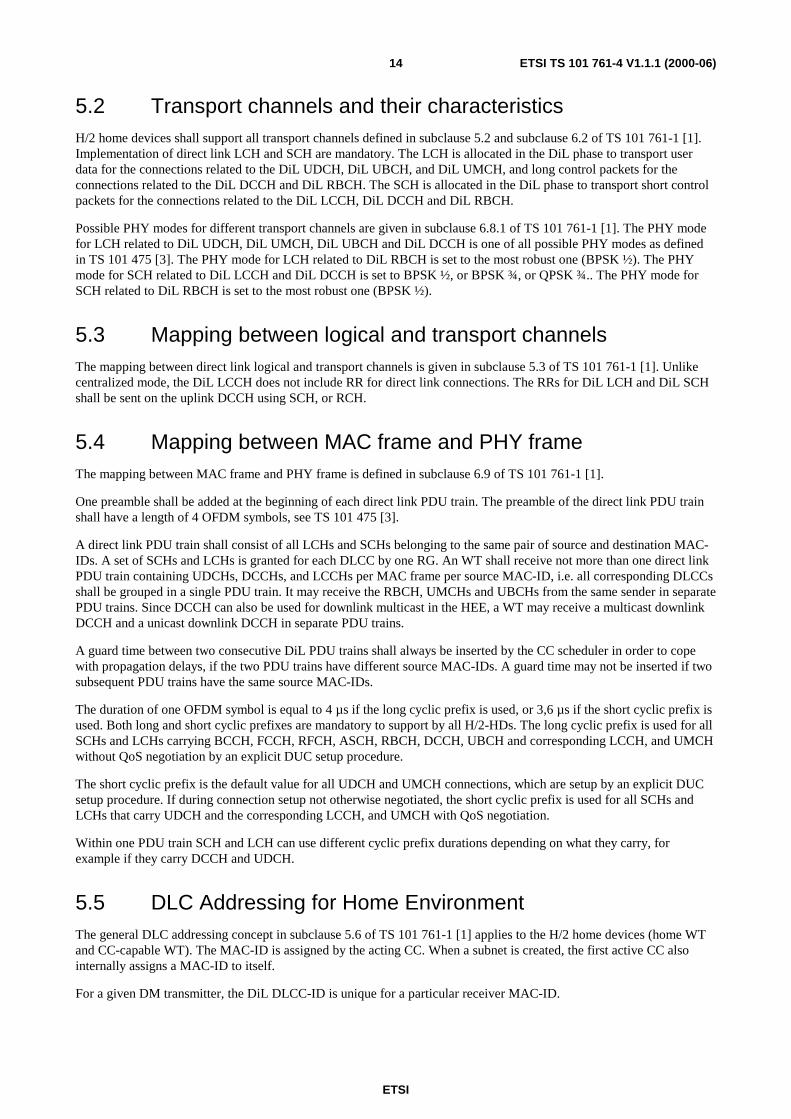
The basic MAC frame structure for H/2-HDs is shown in Figure 1. Each MAC frame shall consist of the transportchannels BCH, FCH, ACH and at least one RCH. If user data is to be transmitted, a DiL phase shall be provided. Ifdownlink control data is to be transmitted (DL RBCH and/or DL DCCH), a DL phase shall be provided. If uplinkcontrol data is to be transmitted (UL DCCH), an UL phase shall be provided. A BCH, an ACH, a minimum length FCHand at least one RCH shall exist in every MAC frame. The duration of the BCH is fixed. The duration of the FCH, DLphase, DiL phase, UL phase and the number of RCHs are dynamically adapted by the CC depending on the currenttraffic situation. The order shall be: BCH – FCH - ACH - DL phase – DiL phase - UL phase – RCHs, from the point ofview of a WT.
NOTE: The specified order is from an WT's point of view. This means that a CC may e.g. have several DL, DiL,and UL phases and mix the phases, as long as the order is kept for each individual WT.
ETSI
ETSI TS 101 761-4 V1.1.1 (2000-06)16
DL phaseBCH FCH UL phase RCHs
MAC-Frame MAC-Frame MAC-Frame MAC-Frame
ACH DiL phase
Figure 1: Direct Mode MAC frame structure
Detailed rules for the composition of MAC frames are given in subclause 6.3.2 of TS 101 761-1 [1].
5.6.2 Resource request and resource grant for direct link
Resource Requests for direct link LCH and SCH are transmitted in RCH or in uplink DCCH using SCH withDLCC-ID = 0. No RR for DiL shall be sent in DiL LCCH. The rules for composing and transmitting RR for DiL aredescribed in subclause 6.2.9.1.2 of TS 101 761-1 [1]. A RR for DiL is always related to a simplex connection whosedirection is determined by the source and destination MAC-IDs in RRs.
Resource Grants for direct link LCH and SCH are described in subclause 6.2.2.2 of TS 101 761-1 [1]. Like centralizedmode, they are sent in FCCH. RG for DiL is always related to a simplex connection whose direction is determined bythe source and destination MAC-IDs in RG.
5.6.3 DiL LCCH for ARQ
Direct link LCCH is defined in subclause 5.1.10 and subclause 6.2.9 of TS 101 761-1 [1]. It is only used for the ARQprotocol performed between two H/2-HDs in DM. The acknowledged mode of error control, the ARQ protocol, isdescribed in subclause 6.4.2 of the TS 101 761-1 [1]. The ARQ protocol of HIPERLAN/2 is symmetric. The ARQprotocol is the same for two WTs in DM and for one WT and the CC in DM. ARQ feedback and the discard messagefor DiL have the same format as those for downlink. As in DL LCCH there is no ABIR in the ARQ feedback message inDiL LCCH. This is because the receiver of a DiL UDCH is not able to signal an increase in ARQ feedback bandwidthrequirement to the CC by means of ARQ feedback messages in the DiL LCCH. Thus, the scheduler in the CC has toschedule sufficient DiL LCCH resources for ARQ feedback transmission.
5.6.4 DiL DCCH for RLC
Direct link DCCH is defined in subclause 5.1.6 and subclause 6.2.5 of TS 101 761-1 [1], and used for RLC messageexchange between any two H/2-HDs in DM, or from a DM sender to a group of DM receivers. It is mapped to eitherDiL LCH or DiL SCH. This logical channel will be used, for example, by DiL power control and link qualitycalibration.
5.6.5 DiL RBCH for RLC
Direct link RBCH is defined in subclause 5.1.5 and subclause 6.2.4 of TS 101 761-1 [1], and used for RLC messagebroadcast from any one H/2-HD to all other H/2-HDs. It is mapped to either DiL LCH or DiL SCH. This logical channelwill be used, for example, by link quality calibration.
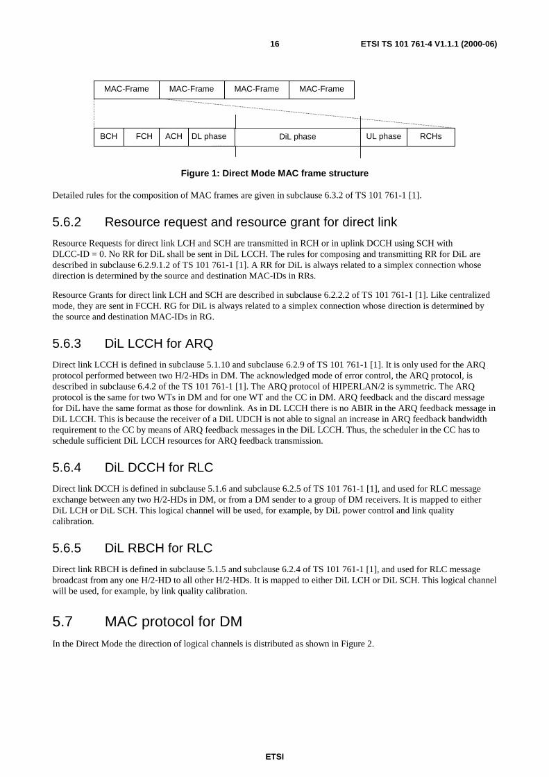
5.7 MAC protocol for DMIn the Direct Mode the direction of logical channels is distributed as shown in Figure 2.

ETSI
ETSI TS 101 761-4 V1.1.1 (2000-06)17
WT1 WT2
CC
UL DCCH (RR)
DiL UDCH
DiL LCCH
FCCH (RG) FCCH (RG)
Figure 2: Direct Mode MAC protocol principle
In Figure 2 WT 1 has a DiL connection to WT 2. As in centralized mode Resource Grants (RGs) are transmitted by theCC in the FCCH. Resources granted for DiL connections are related to DiL UDCH for User data and related to DiLLCCH for ARQ control messages (ARQ feedback and discard). PDUs in the DiL UDCH and discard PDUs in the DiLLCCH are directly transmitted from WT 1 to WT 2. ARQ feedback PDUs are directly transmitted from WT 2 to WT 1.The CC does not listen to the DiL UDCH and DiL LCCH if it is not a peer entity of the DiL connection.
NOTE 1: The CC itself can act as a WT and thus it can be the source and/or destination of DiL connections.
Resources for the DiL LCCH in case of ARQ feedback shall not be requested using RRs. The scheduling of sufficientresources for ARQ feedback is the task of the scheduler in the CC.
Resources for the DiL LCCH for transmission of a discard message are requested with a RR for DiL. RRs for DiL aretransmitted in the RCH or UL DCCH (DLCC-ID=0).
Resource requests shall be used for DiL UDCH, DiL RBCH, DiL DCCH, DiL UMCH, DiL UBCH, and, in case ofdiscard messages, also used for DiL LCCH. The rules for generating RR for DiL are described in subclause 6.2.9.1.2 ofTS 101 761-1 [1]. The priority rules for using granted DiL SCH is described in subclause 6.2.2.2 of TS 101 761-1 [1].The general MAC protocol described in subclause 6.3 of TS 101 761-1 [1] applies to H/2-HDs.
NOTE 2: If the CC itself is requesting resources for DiL UDCH, DiL RBCH, DiL DCCH, DiL UMCH, DiL UBCH,and, in case of discard messages, for DiL LCCH, these resources are requested internally and no DiL RRis transmitted. The message for requesting resources internally in the CC is implementation-specific andoutside the scope of the present document.
5.8 EC protocol for DM
5.8.1 General
The EC protocol is described in subclause 6.2.2.2 of TS 101 761-1 [1]. The general aspects and the usage of EC in DMare described here. Additionally an FEC mode is supported.
The CC and WT shall support four error control modes:
1) Acknowledged mode;
2) Repetition mode;
3) Unacknowledged mode;
4) FEC mode.
DiL UDCHs for a certain connection shall either be sent in acknowledged mode, unacknowledged mode, or FEC mode.The negotiation during connection setup is defined by the corresponding DUC setup procedure. In case of theacknowledged mode, an implicit bidirectional DiL LCCH is set up.

ETSI
ETSI TS 101 761-4 V1.1.1 (2000-06)18
DiL UMCH shall either use the unacknowledged mode or the FEC mode.
DiL DCCH on LCH and DiL RBCH on LCH shall use the unacknowledged mode.
DiL UBCHs shall either be sent in repetition mode or unacknowledged mode. In the case where multiple convergencelayers are supported, the DiL UBCHs may use different error control modes. In the case of the repetition mode, animplicit unidirectional DiL LCCH is set up corresponding to a DiL UBCH.
The figures below illustrate the possible setups. In these examples, the terms "transmitter" and "receiver" mean that thedata transmission under consideration is from the transmitter to the receiver, although e.g. a connection using the DiLUDCH may be bidirectional. The RR message control flow is not considered here.
Figure 3 illustrates the situation in the case of the acknowledged mode. A corresponding DiL LCCH is available whichis used for ARQ feedback messages from the receiver to the transmitter and for discard messages from the transmitter tothe receiver.
Transmitter
DiLUDCH
DiLLCCH
Receiver
DiLUDCH
DiLLCCH
Figure 3: Illustration of the data and control flow in acknowledged mode
Figure 4 illustrates the situation in the case of the repetition mode. In this case, an implicit unidirectional DiL LCCH fordiscard messages from the transmitter to the receiver is available.
Transmitter
DiLUBCH
DiLLCCH
Receiver
DiLUBCH
DiLLCCH
Figure 4: Illustration of the data and control flow in repetition mode
Figure 5 illustrates the situation in the case of the unacknowledged mode. The data flows only from the transmitter to thereceiver, no control data flow for ARQ feedback or discard messages is allowed.
Transmitter
DiLUBCH
DiLUMCH
DiLRBCHin LCH
DiLDCCHin LCH
Receiver
DiLUBCH
DiLUMCH
DiLRBCHin LCH
DiLDCCHin LCH
DiLUDCH
DiLUDCH
Figure 5: Illustration of the data and control flow in unacknowledged mode

ETSI
ETSI TS 101 761-4 V1.1.1 (2000-06)19
Figure 6 illustrates the situation in the case of the FEC mode. The data flows only from the transmitter to the receiver,no control data flow for ARQ feedback or discard messages is allowed.
Transmitter
DiLUMCH
Receiver
DiLUMCH
DiLUDCH
DiLUDCH
Figure 6: Illustration of the data and control flow in FEC mode
5.8.2 Error Control (EC) protocol for the acknowledged mode
The acknowledged mode uses an ARQ protocol and is described in subclause 6.4.2 of TS 101 761-1 [1]. Most parts ofthe ARQ procedures of the transmitter and receiver are the same for CM and DM. Some special treatments for the directlink connections are summarized below.
5.8.2.1 Handling of Dynamic ARQ bandwidth allocation for DM
The number of SCHs available for ARQ feedback messages may change from MAC frame to MAC frame. Therefore thenumber of bitmap blocks that can be signalled in a frame changes dynamically, as determined by the CC scheduler.
In CM the destination of UL ARQ feedback is the CC and thus the CC scheduler. Therefore, it is possible to signalincreased ARQ feedback capacity needs by setting the ABIR bit to 1 in the UL ARQ feedback message. In DM thedestination of DiL ARQ feedback is the peer WT and not the CC scheduler. Therefore, the ABIR bit is not available forthe direct link.
NOTE: The calculation of the amount of extra SCH capacity granted by the scheduler in the CC is out of thescope of the present document.
5.8.2.2 Setting of the ARB in the RR for DiL
In the case of a WT as a transmitter which is completely stopped (e.g. it has new LCHs to transmit but transmission issuspended by flow control or due to a stalled window), the WT may send a RR for DiL with #LCH=0 and ARB=1.Upon reception of such a RR for DiL, the CC scheduler should allocate appropriate resources for the receiving WT totransmit ARQ feedback messages. This allows the transmitter to inform the CC scheduler that it does not get sufficientfeedback from the receiver.
5.8.2.3 Receiver actions in case of insufficient ARQ feedback resources(informative)
If the receiver detects that it does not get enough resources granted for ARQ feedback transmission, it may perform thefollowing action (informative):
• The receiver may request a more robust PHY mode for this specific connection, by setting a more robust PHYmode in a RR for this DiL connection. The #LCH and #SCH shall be set to zero, if no resources are to berequested. With a more robust PHY mode the number of reception errors may be decreased and thus the amountof ARQ feedback to signal negative acknowledgement. The amount of necessary CumAcks is not affected by thePHY mode setting.
In DM a Receiver cannot signal directly to the CC scheduler that the ARQ feedback resources are insufficient (seesubclause 5.8.2.1).
ETSI
ETSI TS 101 761-4 V1.1.1 (2000-06)20
5.8.2.4 Transmitter actions in case of insufficient ARQ feedback resources(informative)
If the transmitter in DM is stopped, which means that within the transmitters window or flow control (FC) limitation,neither unacknowledged nor negatively acknowledged nor new LCHs are to be transmitted due to lack of ARQ feedbackeven if the transmitter buffer is not empty, the transmitter may set ARB in the DiL RR as described in subclause 5.8.2.2.
If the transmitter in DM is not stopped, it is not allowed to use ARB=1 and #LCH=0 to signal to the CC scheduler that itwishes to have more frequent ARQ feedback.
5.8.2.5 Scheduling of sufficient ARQ feedback resources (informative)
The CC scheduler shall schedule sufficient resources for ARQ feedback. The definition of sufficient resources and thescheduling algorithm is outside the scope of the present document. Following informative text is given to indicate theparameters which influence the need for ARQ feedback:
• The minimum necessary ARQ feedback resources are given by the number of transmitted (scheduled) UDCH andthe negotiated ARQ window size. At least one LCCH for ARQ feedback has to be scheduled if as many UDCHhave been scheduled as the size of the ARQ window. This minimum number is far too low for proper operation.
• The average PDU error rate influences the number of necessary ARQ feedback messages. As this number is notknown to the CC scheduler, an estimation has to be made. A worst case assumption is 10%, as if Link Adaptationin the Receiver works properly, the Receiver asks for a more robust PHY mode if the PDU error rate exceeds10%. Proper operation of the ARQ protocol with an average PDU error rate of more than 10% is unlikely.
• In order to limit the delay, the CC scheduler shall take into account the last time it has scheduled a DiL LCCH forARQ feedback. The time between ARQ feedback signalling influences the total ARQ delay.
• If the receiver requests a more robust PHY mode the CC scheduler may check whether it had scheduled sufficientresources for ARQ feedback. By scheduling more resources for ARQ feedback the Receiver may decide to askfor the former PHY mode again, if the reason for asking for a more robust PHY mode has been insufficientresources for ARQ feedback (see subclause 5.8.2.2).
In order to improve the system performance the CC scheduler shall spend spare resources for ARQ feedback, ifpossible.
5.8.3 EC protocol for the repetition and unacknowledged mode
The EC protocol for the repetition mode and the unacknowledged mode is described in subclauses 6.4.3 and 6.4.4 ofTS 101 761-1 [1], respectively.
There are no differences between DM and CM for the EC protocol for the repetition mode and the unacknowledgedmode.
5.8.4 EC protocol for the FEC mode
5.8.4.1 Principles
When setting up a DiL UDCH or UMCH, a H/2-HD can determine if the DLC FEC mode shall be applied to thisconnection. When the FEC mode is selected, both acknowledged mode and unacknowledged mode are no longerpossible for this connection.
The DLC FEC scheme is based on a Reed-Solomon (RS) block code working on a multiple LCH-PDUs. For 8-bitsymbols, the block length of the mother code shall be 2^8-1 = 255 bytes. To achieve an error correction capability of 8bytes per block, 16 bytes of redundancy shall be computed per block, leaving up to 239 bytes for protected data; hence,the mother code is a RS(255, 239) code. Out of these 239 bytes only 200 bytes shall be utilized by the DLC FEC, therest is padding bytes which shall be only needed for computation but shall not be transmitted. The shortened code isreferred to as a RS(216,200) code.

ETSI
ETSI TS 101 761-4 V1.1.1 (2000-06)21
To suit the DLC FEC scheme, an additional UDCH message format is described which takes into account the specificinformation added by the FEC. DLC SDUs shall be concatenated in groups of 4 resulting in 200 bytes of protected data,as explained in subclause 5.8.4.3.
The performance of the FEC scheme is further enhanced by the insertion of a convolutional interleaver with a depth of12 DLC PDUs.
NOTE: In DLC FEC mode, the packet error rate may be more affected by the error rate of RR and/or RG for theparticular connection than by the residual error probability of the FEC scheme itself. In this case, fixedslot allocation as presented in subclause 6.6.1 could be a means to avoid this limitation.
5.8.4.2 UDCH message format
The non-ARQ mode is mainly intended to be used for the UDCH channel. The basic format of such a message is definedin the DLC basic TS (Table 1 and Table 2):
Table 1: Content of the UDCH with CRC
Name Length (bits) PurposePDU type 2 See Table 2
SN 10 Sequence number (provided by EC function)Payload 49.5 × 8 Payload field, i.e. DLC SDU
CRC 24 CRC-24 checksumTotal: 54 x 8
Table 2: LCH Type field
PDU type Purpose00 Normal DLC PDU (carries UDCH, DCCH and RBCH)01 Dummy LCH10 Future use11 Future use
In case the DLC FEC is used, the UDCH message format is as shown in Table 3.
Table 3: Content of the UDCH with FEC
Name Length (bits) PurposePDU type 2 See Table 2
Sync 2 Sync bits needed by FEC functionPayload 49.5 × 8 Payload field (DLC SDU)
FEC 32 One quarter of the RS redundancyTotal: 54 x 8

ETSI
ETSI TS 101 761-4 V1.1.1 (2000-06)22
8 7 6 5 4 3 2 1
1 PDU type Sync MSB
2
3
4 Payload
5
50
51 FEC
52
53
54
Figure 7: UDCH transfer syntax with FEC
5.8.4.3 RS word generation
Every RS word is constructed from data of 4 LCH PDUs of 54 bytes. An RS word shall be obtained from 4 consecutivepayload fields of 49.5 bytes each, originating from the upper layer, or generated by the DLC in case of dummy RSwords.
The PDU type shall be correctly set according to the Table 2, depending on the nature of the payload. If the payload isgenerated by the DLC as dummy, the PDU type for dummy LCH, which is 01, shall be used.
In FEC mode, dummy LCH PDUs shall not be discarded, but shall be passed to the deinterleaver.
The sync field is set according to Table 4. As can be seen, one sync field out of four is inverted from 00 to 11.
Table 4: LCH Sync field
Sync field Purpose11 PDU #100 PDU #2, #3 and #4

ETSI
ETSI TS 101 761-4 V1.1.1 (2000-06)23
Sync(2 bits)
PDU Type(2 bits)
DLC SDU(48 bytes and 12 bits)
50 bytes
PDU-T Payload SPDU-T Payload SPDU-T Payload SPDU-T Payload
216 bytes
FEC
PDU-T Payload SPDU-T Payload SPDU-T Payload SPDU-T Payload
200 bytes
RS(216,200)
S
S
FEC FEC FEC
Figure 8: RS word generation
The 4 blocks of 50 bytes, are concatenated to form a 200-byte block, where each 50 byte block consists of the 2-bitPDU type, the 2-bit Sync field in front of the 49.5 byte DLC SDU each, 39 zero bytes shall be padded before these 200bytes and the obtained 239 bytes are fed to the RS(255,239) Reed-Solomon code with the following properties:
• Code Generator Polynomial: g(x) = (x+µ0 )(x+µ1 )... (x+µ15), where µ = 02HEX
• Field Generator Polynomial: p(x) = x8 + x4 + x3 + x2 + 1
The 39 zero bytes shall be discarded after computation of the RS code word and shall not be transmitted over the airinterface.
The redundancy of 16 bytes per RS(255, 239) is split into 4 packets of 4 bytes each which are inserted at the end of eachDLC PDU according to Table 5.
Table 5: Redundancy addressing within a RS word
Redundancybytes
#1 #2 #3 #4 #5 #6 #7 #8 #9 #10 #11 #12 #13 #14 #15 #16
PDU #1 #1 #1 #1 #2 #2 #2 #2 #3 #3 #3 #3 #4 #4 #4 #4Octet in the
PDU#51 #52 #53 #54 #51 #52 #53 #54 #51 #52 #53 #54 #51 #52 #53 #54
5.8.4.4 Dummy LCH PDU generation
In the basic DLC TS 101 761-1 [1], the DLC can insert dummy PDUs by setting the PDU type value to 01. The contentof the dummy payload is not specified.
However, in case the DLC FEC mode is used, the Sync field shall always be correctly set according to the rule givenabove, where every fourth Sync field is inverted from 00 to 11, cf. Table 4. The value of the other bits of the dummyPDUs is not specified.
At connection release, the sender shall ensure that always a multiple of four PDUs are transmitted over the air. If this isnot achievable by the user PDUs alone, the sender shall generate up to 3 dummy PDUs to complete the transmission of amultiple of 4 PDUs over the air.
ETSI
ETSI TS 101 761-4 V1.1.1 (2000-06)24
During the connection the sender may also generate as many dummy PDUs as necessary to fill multiple of 4 PDUswithin one MAC frame.
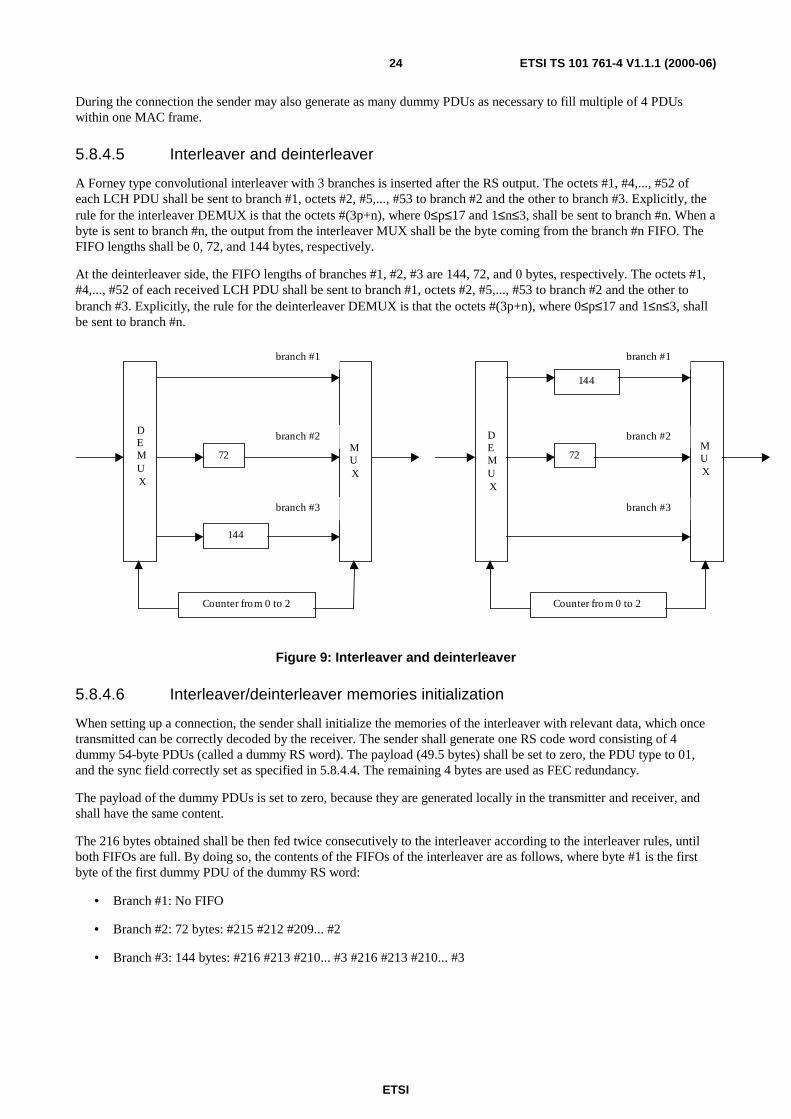
5.8.4.5 Interleaver and deinterleaver
A Forney type convolutional interleaver with 3 branches is inserted after the RS output. The octets #1, #4,..., #52 ofeach LCH PDU shall be sent to branch #1, octets #2, #5,..., #53 to branch #2 and the other to branch #3. Explicitly, therule for the interleaver DEMUX is that the octets #(3p+n), where 0≤p≤17 and 1≤n≤3, shall be sent to branch #n. When abyte is sent to branch #n, the output from the interleaver MUX shall be the byte coming from the branch #n FIFO. TheFIFO lengths shall be 0, 72, and 144 bytes, respectively.
At the deinterleaver side, the FIFO lengths of branches #1, #2, #3 are 144, 72, and 0 bytes, respectively. The octets #1,#4,..., #52 of each received LCH PDU shall be sent to branch #1, octets #2, #5,..., #53 to branch #2 and the other tobranch #3. Explicitly, the rule for the deinterleaver DEMUX is that the octets #(3p+n), where 0≤p≤17 and 1≤n≤3, shallbe sent to branch #n.
144
Counter from 0 to 2
branch #1
branch #2
branch #3
DEMUX
MUX
72
Counter from 0 to 2
branch #1
branch #2
branch #3
144
DEMUX
MUX
72
Figure 9: Interleaver and deinterleaver
5.8.4.6 Interleaver/deinterleaver memories initialization
When setting up a connection, the sender shall initialize the memories of the interleaver with relevant data, which oncetransmitted can be correctly decoded by the receiver. The sender shall generate one RS code word consisting of 4dummy 54-byte PDUs (called a dummy RS word). The payload (49.5 bytes) shall be set to zero, the PDU type to 01,and the sync field correctly set as specified in 5.8.4.4. The remaining 4 bytes are used as FEC redundancy.
The payload of the dummy PDUs is set to zero, because they are generated locally in the transmitter and receiver, andshall have the same content.
The 216 bytes obtained shall be then fed twice consecutively to the interleaver according to the interleaver rules, untilboth FIFOs are full. By doing so, the contents of the FIFOs of the interleaver are as follows, where byte #1 is the firstbyte of the first dummy PDU of the dummy RS word:
• Branch #1: No FIFO
• Branch #2: 72 bytes: #215 #212 #209... #2
• Branch #3: 144 bytes: #216 #213 #210... #3 #216 #213 #210... #3

ETSI
ETSI TS 101 761-4 V1.1.1 (2000-06)25
To save radio resources, no byte from the interleaver output shall be sent over the air during the FIFO initializationprocess, since the receiver deinterleaver can initialize its memory locally by using the same dummy RS words. With thesame dummy RS word stored locally, the deinterleaver can achieve an equivalent initialization by taking into accountthe expected interleaver output and the deinterleaver rule. This results in the following FIFO contents in thedeinterleaver branches after the equivalent initialization:
• Branch #1: 144 bytes: #214 #211 #208... #1 #214 #211 #208... #1
• Branch #2: 72 bytes: #215 #212 #209... #2
• Branch #3: No FIFO
Consequently, when a user PDU coming from the sender CL is input to the interleaver, the first outgoing byte at thedeinterleaver output is byte #1 of the dummy RS word, and the n-th byte at the deinterleaver output is byte #n of thedummy RS word. Thus, the RS decoder works correctly.
5.8.4.7 Connection termination
In case a connection uses the DLC FEC mode, the end-to-end delay due to the interleaver-deinterleaver process equals 8PDUs. Hence, if a receiver has to decode the last PDU of a connection before the connection release, the sender shalltake 2 actions:
1) If a multiple of 4 PDUs is not achieved, add the missing number (1, 2 or 3) of dummy PDUs to complete aRS word.
2) Purge the whole memories by generating two dummy RS words before releasing the connection.
NOTE: The payload of the dummy PDUs used for completing the RS words and for purging can be of any values.
Doing so, it is ensured that the last useful PDU is always read out of the deinterleaver, while the purging dummy RSwords remain in the memories of the interleaver and the deinterleaver.
5.9 Broadcast TransmissionThe downlink broadcast channels BCCH, FCCH, RFCH, RBCH and UBCH shall only be used by the acting CC. TheBCCH is transmitted in the BCH and is identified by the occurrence of the BCH. The FCCH is transmitted in the FCHand is identified by the occurrence of the FCH. The RFCH is transmitted in the ACH and is identified by the occurrenceof the ACH. The downlink RBCH is announced in the FCCH and is identified by MAC ID = 0 and DLCC ID = 0 in thecase of the downlink. The downlink UBCH for a particular convergence layer is identified by the unique MAC ID thatshall be assigned dynamically by the RLC (see TS 101 761-2 [2]) in the CC, taken from the MAC ID range 1 to 223,and DLCC ID = 63.
The direct link broadcast channels RBCH and UBCH can be used by any H/2-HD to distribute control and user data,respectively, to all other H/2-HDs. The direct link RBCH is identified by the source MAC ID of the transmitting H/2-HD, destination MAC ID = 0, and DLCC ID = 0. The direct link UBCH for a particular convergence layer is identifiedby the unique destination MAC ID that shall be assigned dynamically by the RLC (see TS 101 761-2 [2]) in the CC,taken from the MAC ID range 1 to 223, the source MAC ID of the transmitting H/2-HD, and DLCC ID = 63.
In both the CM and DM, the transmit power shall be adapted to the decoding quality of the farthest receiver.

ETSI
ETSI TS 101 761-4 V1.1.1 (2000-06)26
5.10 EncryptionH/2-HDs shall encrypt UDCH, UMCH, UBCH and DCCH messages carried by LCHs using the DES algorithm. TheRBCH is not encrypted (see TS 101 761-1 [1]). Encryption of SCHs is not possible. The implementation and use of theTriple DES is optional (TS 101 761-1 [1]). In TS 101 761-1 [1] and TS 101 761-2 [2] a unicast encryption key is usedby every WT for encrypted UL/DL communication on LCHs with the CC. In the HE most of the communication linksare DiLs between two WTs. On these DiLs the unicast keys cannot be used. In a subnet, all DiL LCHs sent by a H/2-HDtherefore shall use one single encryption key. This key is thus a common key; it is called DM Common Key. The onlycase, where H/2-HDs do not communicate over DiLs, is the sending/reception of RLC messages to/from the CC. Theconcerned channels are UL DCCH, DL DCCH and DL RBCH. In contrast to TS 101 761-1 [1], in the HE DL DCCH isalso used for point-to-multipoint communication. This implies the use of the Common Key in the case of DL DCCH.For this reason and for the sake of simplicity, H/2-HDs shall use the same DM Common Key also for UL DCCH and DLDCCH. Furthermore, this solution has the advantage that no unicast encryption keys need to be transferred in case of aCC Responsibility Handover.
NOTE: DL RBCH remains un-encrypted in HE.
Since the DM Common Key shall be distributed to the WT in a secure way, it is nevertheless necessary that a unicastencryption key is generated by each WT during its assocication at the CC. For this purpose each H/2-HD shallimplement the DES algorithm, whereas the implementation of the Triple DES is optional (TS 101 761-1 [1]). Thechoice of the encryption algorithm to be used for this purpose is negotiated between the CC and the WT duringassociation (TS 101 761-2 [2]).
During association the usage of the DM Common Key Distribution procedure shall be announced in the RLC-LINK-CAPABILITY-ACK message by setting the parameter DM-USE-COMMON-KEY to the value use-common-key. DM-USE-COMMON-KEY = no-common-key is not allowed for any H/2-HD.
The CC shall generate a common key (see TS 101 761-2 [2]), define a Key Identifier for it, and call this key theDM Common Key. This key shall then be used for the encryption of all DiL as well as UL/DL DCCH LCHs of all H/2-HDs in the subnet. In case a low number of common keys is desirable, it is allowed to reuse the DM Common Key asDL Broadcast and DL Multicast Common Key.
The DM Common Key Distribution shall be always carried out after the downlink and uplink unicast Encryption Startupprocedure (see TS 101 761-2 [2]), after the authentication following the unicast encryption startup (association withauthentication). In the DM Common Key Distribution procedure the CC shall send a messageRLC_DM_COMMON_KEY_DISTR to the associating WT. The WT shall reply with the messageRLC_DM_COMMON_KEY_DISTR_ACK. Authentication is mandatory for all installed H/2-HDs, that havesuccessfully completed the PIN and time-window protected authentication key exchange process in subclause 6.9.
The message RLC_DM_COMMON_KEY_DISTR defines the encryption algorithm that is used and contains theCommon Key Identifier and the DM Common Key. Since the message is encrypted with the downlink/uplink unicastkey, the DM Common Key cannot be read by an eavesdropper.
The response message RLC_DM_COMMON_KEY_DISTR_ACK contains the descriptor of the encryption algorithmas a confirmation and a hash sum of the Common Key Identifier and the DM Common Key. The hash sum consists ofthe MD5 sum on the concatenation of the Common Key Identifier and the DM Common Key.
The unicast encryption key shall be used to encrypt all sent messages during the association procedure, but in the HE itshall be never used after the association procedure has ended. Once associated, a H/2-HD shall always use the CommonKey for the encryption of (DiL and UL/DL DCCH) LCHs.
Once the DM Common Key is received by a H/2-HD, it shall use the encryption and decryption procedure in subclause6.7.4 of TS 101 761-1 [1] to encrypt and decrypt LCHs to and from other H/2-HDs. The seed sent periodically by theCC in downlink RBCH is used to support the generation of the Initialization Vector (IV) in each WT. All H/2-HDs havea seed generator, which cycles stepwise in the same way to produce non-repeating seeds (before it wraps) for each MACframe. The seed generator of a WT shall be reset by the newly received seed from the CC, if its decoding was successful(TS 101 761-1 [1]). A new IV is used for each DiL LCH. The IV is a function of the locally generated seed and the 12LSBs of the start pointer value in the FCCH IE for that particular connection. This ensures the synchronization of theencryption and decryption processes for each connection, although only a single DM Common Key is used for allencrypted LCHs and all H/2-HDs.
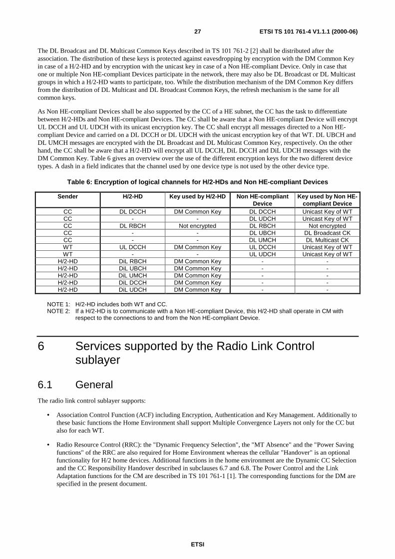
ETSI
ETSI TS 101 761-4 V1.1.1 (2000-06)27
The DL Broadcast and DL Multicast Common Keys described in TS 101 761-2 [2] shall be distributed after theassociation. The distribution of these keys is protected against eavesdropping by encryption with the DM Common Keyin case of a H/2-HD and by encryption with the unicast key in case of a Non HE-compliant Device. Only in case thatone or multiple Non HE-compliant Devices participate in the network, there may also be DL Broadcast or DL Multicastgroups in which a H/2-HD wants to participate, too. While the distribution mechanism of the DM Common Key differsfrom the distribution of DL Multicast and DL Broadcast Common Keys, the refresh mechanism is the same for allcommon keys.
As Non HE-compliant Devices shall be also supported by the CC of a HE subnet, the CC has the task to differentiatebetween H/2-HDs and Non HE-compliant Devices. The CC shall be aware that a Non HE-compliant Device will encryptUL DCCH and UL UDCH with its unicast encryption key. The CC shall encrypt all messages directed to a Non HE-compliant Device and carried on a DL DCCH or DL UDCH with the unicast encryption key of that WT. DL UBCH andDL UMCH messages are encrypted with the DL Broadcast and DL Multicast Common Key, respectively. On the otherhand, the CC shall be aware that a H/2-HD will encrypt all UL DCCH, DiL DCCH and DiL UDCH messages with theDM Common Key. Table 6 gives an overview over the use of the different encryption keys for the two different devicetypes. A dash in a field indicates that the channel used by one device type is not used by the other device type.
Table 6: Encryption of logical channels for H/2-HDs and Non HE-compliant Devices
Sender H/2-HD Key used by H/2-HD Non HE-compliantDevice
Key used by Non HE-compliant Device
CC DL DCCH DM Common Key DL DCCH Unicast Key of WTCC - - DL UDCH Unicast Key of WTCC DL RBCH Not encrypted DL RBCH Not encryptedCC - - DL UBCH DL Broadcast CKCC - - DL UMCH DL Multicast CKWT UL DCCH DM Common Key UL DCCH Unicast Key of WTWT - - UL UDCH Unicast Key of WT
H/2-HD DiL RBCH DM Common Key - -H/2-HD DiL UBCH DM Common Key - -H/2-HD DiL UMCH DM Common Key - -H/2-HD DiL DCCH DM Common Key - -H/2-HD DiL UDCH DM Common Key - -
NOTE 1: H/2-HD includes both WT and CC.NOTE 2: If a H/2-HD is to communicate with a Non HE-compliant Device, this H/2-HD shall operate in CM with
respect to the connections to and from the Non HE-compliant Device.
6 Services supported by the Radio Link Controlsublayer
6.1 GeneralThe radio link control sublayer supports:
• Association Control Function (ACF) including Encryption, Authentication and Key Management. Additionally tothese basic functions the Home Environment shall support Multiple Convergence Layers not only for the CC butalso for each WT.
• Radio Resource Control (RRC): the "Dynamic Frequency Selection", the "MT Absence" and the "Power Savingfunctions" of the RRC are also required for Home Environment whereas the cellular "Handover" is an optionalfunctionality for H/2 home devices. Additional functions in the home environment are the Dynamic CC Selectionand the CC Responsibility Handover described in subclauses 6.7 and 6.8. The Power Control and the LinkAdaptation functions for the CM are described in TS 101 761-1 [1]. The corresponding functions for the DM arespecified in the present document.

ETSI
ETSI TS 101 761-4 V1.1.1 (2000-06)28
• DLC User Connection Control (DUCC): the DUCC contains functions for the establishment and the modificationboth of unicast and multicast connections. The DUCC basic functions in TS 101 761-2 [2] include DUCC for thedirect link unicast and DiL multicast without QoS negotiation. The DiL multicast with QoS negotiation isspecified in subclause 6.6.2 of the present document.
6.1.1 Basic RLC Functions applied
The following concepts of the RLC basic functions TS 101 761-2 [2] have been adopted:
- Usage of DLC logical and transport channels for RLC messages;
- Transfer Syntax of RLC (except DiL and DL multicast DCCH);
- Sequencing of RLC messages;
- ASN.1 definition of the RLC PDUs;
- Timers and repetitions of RLC messages.
6.1.1.1 DLC User Connection Control
The DUCC contains functions for the establishment, modification and release of unicast, multicast and broadcastconnections. Furthermore the DUCC for direct link unicast is described in TS 101 761-2 [2].
6.1.1.2 Radio Resource Control
Dynamic Frequency Selection
The Dynamic Frequency Selection (DFS) is applied in the HE in the way it is supported by the TS 101 761-2 [2]. TheDFS shall avoid the interference of other devices using the same frequency band that may arise from neighbouring H/2networks using the same frequency or Non HE-compliant Devices on the frequency band. The H/2 DFS scheme iscentralized to CCs. Every CC collects measurement results and chooses the operating frequency independently of otherCCs.
MT Absence
The MT Absence function is for WT maintenance purposes (scanning channels, etc.). The MT Absence in CM isdefined in [2]. The MT Absence in DM does not differ from the procedure in CM. In DM, the user packets to betransmitted to a WT in the absence state are queued in the transmitting WT, not in the CC.
6.1.2 Changed RLC Functions
6.1.2.1 Association Control Function
In HE, the CC is determined as a result of the CC Selection process. Its role is handed over to another CC-capable H/2-HD after a successful CC responsibility handover. A HE-compliant H/2-HD shall only try to associate with the CCwhose NET-ID matches that stored in the H/2-HD, see subclause 6.9. If more than one such CC is detectable, the H/2-HD shall first try to associate with the CC with the best receive quality. Since the NET-ID is just a random number, it ispossible that the same NET-ID value is used by a nearby non HE-compliant CC. Therefore, the HE-compliant H/2-HDshall abort the association process with a CC, as soon as it detects that this CC is not HE-compliant. Re-association withthis Non HE-compliant CC is optional, if the HE-compliant H/2-HD cannot find any other HE-compliant CC with thesame NET-ID, and if it is unable or not willing to become the CC of the HE-compliant network.
NOTE 1: A manufacturer can implement on an H/2-HD different usage profiles. By selecting a Non HE-compliantusage profile, the user can configure a H/2-HD as a Non HE-compliant device to be preferably associatedwith a non HE-compliant CC.
NOTE 2: A H/2-HD acting as CC may allow a Non HE-compliant Device to associate with the network. In thiscase, all H/2-HDs having communications with that Non HE-compliant Device shall operate in CM withrespect to all connections to and from that Non HE-compliant Device.
ETSI
ETSI TS 101 761-4 V1.1.1 (2000-06)29
Terminal Association for Multiple CLs
After the RBCH Association message transfer the list of CL-IDs is processed by the WT. The WT shall abort theassociation process if there are no corresponding CLs supported. If several CLs are supported both by the CC and theWT, the WT shall select CL IDs according to a set of rules that are defined in subclause 6.2. The WT transmits theselected CL-ID-list to the CC in the RLC_LINK_CAPABILITY message which is sent after the MAC ID assignment.
6.1.2.2 Radio Resource Control
Handover
The "Radio Handover", "Network Handover" and "Forced Handover" as described in the TS 101 761-2 [2] are onlyoptional for H/2-HDs, since no cellular infrastructure can be assumed for private homes.
Power Saving
The Power Saving functions are initiated by the WT with the purpose of entering or leaving low consumption modes andcontrolling the power of the transmitter. Direct link connections addressed to a WT that is in a power saving state shallnot be scheduled by the CC. The CC shall wake up the sleeping WT, when detecting another WT having pending datafor this sleeping WT.
6.1.3 Changed RLC Messages, Parameter Settings
6.1.3.1 Association Control Function
In the home environment no Network Operator ID shall be applied. Therefore the NOP-ID field shall not be used in theRBCH Association message.
The parameters exchanged during association and being relevant to H/2-HDs are described below:
direct-mode-cap: The value of the direct-mode-cap field shall be set to 1 ("dm-capabilities") for all H/2-HDs. (message: RLC_LINK_CAPABILITY).
cl-vid-list: H/2-HD may support more than one CLs. The IDs of these CLs shall be included in thisCL-ID-List (messages: RLC_RBCH_ASSOCIATION, RLC_LINK_CAPABILITY).
support-fsa: H/2-HDs supporting isochronous services shall support FSA, and set Support-FSA field tothe value 1 ("support-fsa") (message: RLC_LINK_CAPABILITY,RLC_LINK_CAPABILITY_ACK).
cc-ho-cap: A CC-capable H/2-HD supporting CC responsibility handover shall set this paramter fieldto cc-ho-supported. (message: RLC_LINK_CAPABILITY).
dm-use-common-key: This parameter field is used to indicate if the DM Common Key distribution procedure isperformed. It shall be set to the value "use-common-key". (message:RLC_LINK_CAPABILITY).
dm-attributes: The parameter field dil-power-control shall be set to dil-dynamic-pc, the parameter fieldsrx-arq-win-size and tx-arq-win-size shall be set to the supported ARQ window size.(message: RLC_LINK_CAPABILITY, RLC_LINK_CAPABILITY_ACK).
6.1.3.2 DLC User Connection Control
The following parameters contained in the setup/modify messages for DiL UDCH and DiL UMCH shall be set asfollows:
cl-id: This parameter shall be set to the ID of the CL instance that sets up or modifies a DiLUDCH or DiL UMCH.
NOTE: CL-ID is also used by the join and leave procedures for DiL UBCH or DiL UMCH.
ETSI
ETSI TS 101 761-4 V1.1.1 (2000-06)30
allocation-type: The allocation-type parameter in duc-descr describes the type of connection: basic, fca, orfsa. fec-used: The fec-used flag shall be set for each DiL UDCH or DiL UMCH thatuses FEC mode.
fec: The fec field defines the coder type and the interleaver type of the applied FEC.
6.1.4 New RLC Functionality
CC Selection, CC Responsibility Handover
Because of the ad hoc network topology, additional functions like the CC selection procedure and the CC ResponsibiltyHandover procedure are introduced in subclauses 6.7 and 6.8. Support for CC Selection is mandatory for CC-capableH/2-HDs.
Direct Link related Functions
Support for DiL Link Adaptation, DiL Power Control, and Link Quality Calibration, are mandatory for H/2-HDs. Thecorresponding functions are specified in subclauses 6.3, 6.4, and 6.5.
The DiL UMCH setup/modify/release is specified in subclause 6.6.2, and the use of DiL UBCH is specified in subclause5.9. The support for DiL UMCH and DiL UBCH is mandatory for H/2-HDs.
Authentication Key Exchange
The Key Exchange with special reference to direct link requirements is specified in subclause 6.9.
6.2 Terminal association for multiple convergence layersIn the HE multiple active CLs may make use of multiple CLs, since WTs may be connected to different types of fixednetworks, for example IEEE 1394 and Ethernet. In this case, the terminal association is done in several steps. In theRBCH Association procedure the CC shall inform the WT about the CLs supported in parallel by the CC, using the cl-vid-list parameter. During the link capability procedure, the WT informs the CC about the CLs it wants to associatewith, also using a cl-vid-list. The WT´s cl-vid-list shall be a sub-set of the cl-vid-list sent by the CC. If none of the CLIDs sent in RBCH association message is supported by the WT, the WT shall not continue with the association.
In case of successful negotiation of CL-IDs, the info transfer procedure (see TS 101 761-2 [2]) shall be subsequentlyperformed between the WT and the CC for each selected CL-ID. Per CL-ID one info transfer is performed. The formatof the INFO_PDU is described in TS 101 761-2 [2]. After successful association of the CLs, the CL-specific C-SAP(s)and U-SAP(s) are created for the individual CL-IDs. During DiL UDCH or DiL UMCH setup the CL-ID contained inthe messages identifies the C-SAP of the addressed CL. After the setup of a DIL UDCH or DiL UMCH, the DUC-IDimplicitly identifies the U-SAP of the addressed CL.
6.3 Link Adaptation in Direct Link PhaseIn unicast DiL communication only the receiver is allowed to recommend a new PHY mode based upon the packetdecoding quality at any time. In this case the receiver shall set the PHY mode LCH and PHY mode SCH parameters inRR for DiL to the proposed new PHY mode, see subclause 6.2.9.1 of TS 101 761-1 [1]. The parameters #SCH and#LCH shall be set to zero.
NOTE: In contrast to a RR for DiL used for unicast link adaptation (#LCH=#SCH=0), which is issued by areceiver, the RR for DiL with #LCH>0 and/or #SCH >0 can only be sent by the transmitter of a DiLconnection to request LCH(s) and/or SCH(s).
ETSI
ETSI TS 101 761-4 V1.1.1 (2000-06)31
In multicast/broadcast DiL communication, link adaptation shall only be performed in conjunction with dynamic powercontrol in subclause 6.4.2. Here, a new PHY mode shall only be recommended by the sender of a multicast connection,which is defined uniquely by the sender MAC-ID and the multicast MAC-ID. The sender of a multicast connection maypropose a more robust PHY mode, if the transmit power for this connection has reached the upper boundary, and at leastone of its receivers is suggesting a higher transmit power. It can propose a less robust PHY mode, if the transmit powerfor this connection has reached the lower boundary, and all of its receivers are suggesting a lower transmit power. Thesender of the multicast connection shall use a RR for DiL to recommend the new PHY mode for LCH and/or SCH. Itshall set #LCH and/or #SCH to zero, if no real resources are requested by this RR.
For both direct link unicast and multicast, the CC shall not change the PHY mode of a DiL connection withoutrecommendation from the involved WTs.
6.4 Power Control in Direct Link PhaseDynamic power control, in direct link phase, enables the transmitting WT to always set its transmit power levelappropriately, to provide acceptable reception quality at the receiving WT. This is determined according to the explicitrecommendation from the receiver to the transmitter, to increase or decrease its power level by a certain value (dB). Thecriteria the receiver uses to determine this value is implementation specific.
NOTE: The receiving WT might use received signal strength (RSS) or the BER of received data as a criteria forreception quality.
Dynamic power control shall be supported by all H/2 home devices. Dynamic power control for unicast andmulticast/broadcast connections in direct link is described below.
For the purpose of power control in unicast and multicast/broadcast, the message RLC_DM_POWER_CONTROL isused as described below: Since unicast and multicast/broadcast PDUs from the same sender are not necessarily receivedin one PDU train, dynamic power control is performed separatedly. A connection type field dm-duc-type inRLC_DM_POWER_CONTROL indicates whether the recommendation concerns unicast or multicast/broadcast PDUsoriginating from the same sender.
RLC_DM_POWER_CONTROL messages shall be always transmitted using the most robust PHY mode. The transmitpower level may vary, and is specified below.
6.4.1 Direct Link unicast power control
Dynamic power control shall be performed for each unicast DUC in DiL, for both simplex and duplex connections. TwoWTs that have several DUCs, using different PHY modes, would usually require different transmit power levels.However, since PDUs belonging to different DUCs which are sent from one WT to a peer WT in one MAC frame, aretransmitted in a train, the same transmit power level shall be used for all PDUs in the train. The transmit power level isset to satisfy the connection with the worst reception quality (i.e. less robust PHY mode). This is provided by thereceiver's explicit recommendation.
In unicast, the power control scheme in direct link phase is performed as follows:
1) Connectivity Check: performed during the first DiL DUC Setup between a WT pair;
2) Power Update: performed after each DiL DUC Setup involving the same WT pair, and during the lifetime oftheir unicast connections.
During the first DiL DUC Setup, the peer WTs exchange power control messages, in order to check if a direct radio linkis possible. After the first connection setup is successfully completed, and during the life time of the connection, powerupdate is dynamically performed, to inform the sender about appropriate transmit power level. Power update can also beperformed after a further DiL DUC setup between the same WT pair, to take into account different power requirementsfor different PHY modes.

ETSI
ETSI TS 101 761-4 V1.1.1 (2000-06)32
6.4.1.1 Connectivity Check
Connectivity check is performed only for the first DiL DUC between two WTs using RLC_DM_POWER_CONTROLmessages. During the setup of the first unicast DiL DUC (see TS 101 761-2 [2]), the CC enables both WTs to performconnectivity check by granting each WT at least one DiL DCCH to transmit its power control message, using a SCH.The CC itself can be one of the WTs. The CC shall send the RGs to both WTs, after the secondRLC_DM_CONNECT_ACK message (to WT2), and before the first RLC_DM_CONNECT_COMPLETE message (toWT1), have been sent. This is shown in the following MSCs for both CC and WT initiated DUC setup. The CC maygrant resources for connectivity check several times during this period. All these granted DiL DCCH SCHs to this WTpair shall be used for connectivity checking. All RLC_DM_POWER_CONTROL messages sent for connectivity checkshall be transmitted at maximum allowed power level.
CC
RLC_DM_SETUP
WT1 WT2
RLC_DM_CONNECT
RLC_DM_CONNECT_ACK
RLC_DM_SETUP
RLC_DM_CONNECT
RLC_DM_CONNECT_ACK
RLC_DM_CONNECT_COMPLETE
RLC_DM_CONNECT_COMPLETE-ACK
RLC_DM_CONNECT_COMPLETE
RLC_DM_CONNECT_COMPLETE-ACK
DUC_established
- CC grants DCCH SCHs for WT1 and WT2, implicit power control trigger- WT1 transmits RLC power control message, WT2 measures reception quality- WT2 transmits RLC power control message, WT1 measures reception quality
If connectivity check wassuccessful!
If connectivity check wassuccessful!
Figure 10: Direct Link Setup procedure - CC initiated
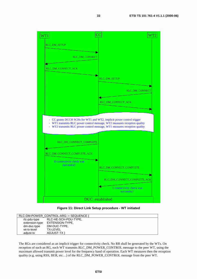
ETSI
ETSI TS 101 761-4 V1.1.1 (2000-06)33
CCWT1 WT2
RLC_DM_SETUP
RLC_DM_CONNECT
RLC_DM_CONNECT_ACK
RLC_DM_CONNECT_COMPLETE
RLC_DM_CONNECT_COMPLETE_ACK
RLC_DM_CONNECT_COMPLETE
RLC_DM_CONNECT_COMPLETE_ACK
DUC_established
RLC_DM_SETUP
RLC_DM_CONNECT
RLC_DM_CONNECT_ACK
- CC grants DCCH SCHs for WT1 and WT2, implicit power control trigger- WT1 transmits RLC power control message, WT2 measures reception quality- WT2 transmits RLC power control message, WT1 measures reception quality
If connectivity check wassuccessful!
If connectivity check wassuccessful!
Figure 11: Direct Link Setup procedure - WT initiated
RLC-DM-POWER_CONTROL-ARG::= SEQUENCE {rlc-pdu-type RLC-HE-SCH-PDU-TYPE,extension-type EXTENSION-TYPE,dm-duc-type DM-DUC-TYPE,wt-tx-level TX-LEVELadjust-tx ADJUST-TX }
The RGs are considered as an implicit trigger for connectivity check. No RR shall be generated by the WTs. Onreception of such an RG, each WT transmits RLC_DM_POWER_CONTROL message to the peer WT, using themaximum allowed transmit power level for the frequency band of operation. Each WT measures then the receptionquality (e.g. using RSS, BER, etc…) of the RLC_DM_POWER_CONTROL message from the peer WT.

ETSI
ETSI TS 101 761-4 V1.1.1 (2000-06)34
Either WT shall abort the DiL DUC connection setup in the following cases:
• It is not granted at least one DiL DCCH SCH, or cannot successfully decode at least one corresponding RG,before receiving the RLC_DM_CONNECT_COMPLETE message from the CC.
• It could not receive the RLC_DM_POWER_CONTROL message, or the reception quality was not acceptable.
In order to reject the DiL DUC Setup the WT shall send RLC_DM_RELEASE message and continue with the DiLRelease procedure.
Either WT shall only acknowledge the RLC_DM_CONNECT_COMPLETE message from the CC withRLC_DM_CONNECT_COMPLETE_ACK, after it has successfully decoded at least oneRLC_DM_POWER_CONTROL message from the peer WT, and it has sent at least oneRLC_DM_POWER_CONTROL message to the peer WT.
In case both WTs successfully acknowledged the RLC_DM_CONNECT_COMPLETE from the CC, the connectivitycheck is considered successful, and the connection setup is successfully completed.
6.4.1.2 Power Update
As long as there is at least one unicast connection between a WT pair, power update is performed whenever it isnecessary. After each further unicast connection setup or release, either WT should consider performing power update,to ensure always satisfying the connection with worst reception quality.
Each WT continuously monitors the received signal quality of all its unicast connections with the peer WT. If a WTdetects a worsening or an improvement of the received signal strength or another reception quality criterion(implementation specific) above an acceptable threshold, it should request a DiL DCCH SCH to transmit aRLC_DM_POWER_CONTROL message. The message contains an explicit recommendation to the peer WT to adjustits transmit power level for unicast traffic appropriately. For the RLC_DM_POWER_CONTROL message transfer theWT shall use the most robust PHY mode. If this message is transmitted together with other PDUs, the regulated Powerlevel, otherwise the maximum transmit power level, shall be used for the unicast transmission.
Even though the radio channel can be considered symmetric in most of the cases, it is recommended that a transmittingWT1 only adapts its power level based on explicit recommendation from the receiving WT2. WT1 should not change itstransmit power level based on the change of its own reception quality for WT2.
Latest, two frames after either WT has successfully decoded the received RLC_DM_POWER_CONTROL messagewith explicit recommendation, it shall start to transmit all its direct link unicast traffic to the peer WT, using the adjustedpower level.
The power control scheme in direct mode should not react on burst changes of the radio channel, rather on persistentchanges. The exact algorithm is implementation specific.
In case the PHY mode is changed during a connection, the WTs might also readjust the transmit power levelsaccordingly.
In addition to the dm-duc-type field and recommendation for power control, the RLC_DM_POWER_CONTROLmessage also contains the current transmit power level of the sender of this message, for all its unicast connections withthe receiving WT. Thus, the receiving WT recognizes whether the transmitter has reached the lower or upper transmitpower limit in the frequency band of operation. In this case, the peer WTs might initiate a change of PHY mode for linkadaptation, see subclause 6.3.
If a WT does not react to a recommendation from its peer WT after two frames, the originator of the recommendationshall retransmit its RLC_DM_POWER_CONTROL message.
In case the receiving WT can no more successfully decode the received user data, it shall transmit itsRLC_DM_POWER_CONTROL message at the maximum transmit power level, informing the sender to increase itstransmit power level to the recommended value. If the receiver is still not able to successfully decode received data, itmight trigger a PHY mode change for link adaptation, before it releases the connection.
RLC_DM_POWER_CONTROL messages can be exchanged anytime by just requesting SCH for DiL DCCH, as long asthere is at least one connection between the WT pair.

ETSI
ETSI TS 101 761-4 V1.1.1 (2000-06)35
6.4.2 Direct Link Multicast/Broadcast Power Control
In the case of multicast and broadcast connections, a quasi static transmit power control scheme shall be applied. Thesender shall start transmission of the first multicast/broadcast connection, at 3 dB below the maximum allowed transmitpower level for the centre frequency where it is operating. No connectivity check is performed in DiL broadcast ormulticast connections (both with and without connection setup).
After multicast/broadcast connection has started (corresponding RGs in FCH), each receiving WT shall send itsRLC_DM_POWER_CONTROL message to the multicast/broadcast sender, latest within a timerT_mc_dm_power_control. A receiving WT that could successfully decode the corresponding user data informs themulticast/broadcast sender to decrease its transmit power level by a certain value. A receiving WT that could notsuccessfully decode the user data requests the multicast/broadcast sender to increase its transmit power levelappropriately. The multicast/broadcast sender shall adjust its transmit power level, in order to satisfy the receiver withthe worst reception quality, i.e. which recommended highest increase or lowest decrease of power level. The sender shallalways ensure that it is compliant with the maximum allowed transmitted power level for the centre frequency where it isoperating.
Similar to unicast, the sender shall always use the same transmit power level for all its active multicast and broadcastconnections, even if different multicast groups are target. The receiving WTs should therefore determine the requiredtransmit power adjustment for a certain multicast/broadcast sender, based on the multicast or broadcast connection withthe worst reception quality.
During the lifetime of all multicast/broadcast connections from the same sender, each receiving WT shall send itsRLC_DM_POWER_CONTROL message to the sender whenever necessary, but not less than once everyT_mc_dm_power_control. The sender should adjust its transmit power level, if it notices that all receiving devices havea persistently acceptable reception quality according to their RLC_DM_POWER_CONTROL messages.Recommendations from multicast/broadcast receivers to increase the transmit power level shall be applied latest twoframes after reception of the corresponding RLC_DM_POWER_CONTROL message. The multicast/broadcast sendershall however not reduce its transmit power level by more than 3 dB within T_mc_dm_power_control. This shall ensurethat the sender does not react to burst characteristics of the radio channel.
Since a new multicast/broadcast connection might require higher transmit power level than already active ones (if it usesdifferent PHY mode, or it targets different multicast receivers), each new multicast/broadcast connection shall be startedat 3 dB below the maximum allowed transmit power level, or the currently used multicast/broadcast power level if it ishigher. Consequently, latest when a new multicast/broadcast connection is started, the sender shall have increased thepower level of all its active multicast/broadcast connections, if it was originally less then 3 dB below the maximumpower. If the power level of active connections already exceeds this level, the same level shall be used for the newconnection as well. After the new multicast/broadcast connection is started, the appropriate transmit power level isdetermined based on the receiver's recommendations.
NOTE: The sender may steadily perform the increase of power level for example during multicast connectionsetup.
RLC_DM_POWER_CONTROL messages for direct link multicast/broadcast power control may be transmitted togetherwith unicast traffic to the multicast sender. In this case, this message may be transmitted at regulated transmit powerlevel for unicast traffic. Otherwise, the RLC_DM_POWER_CONTROL message shall be transmitted using themaximum transmit power level. Thus it can be assumed that the sender can successfully decode the messages from thosereceivers, where direct link connection is possible. The sender may initiate link adaptation (6.3), if the transmit powerfor its multicast/broadcast connections has reached the upper (lower) boundary, and at least one (all) of its receivers issuggesting a higher (lower) transmit power.
A multicast/broadcast receiver may retransmit its RLC_DM_POWER_CONTROL message several times to request thesender increase its power level, if the sender does not satisfy this request within two frames. The receiver may leave themulticast/broadcast group if the reception quality is still not acceptable.
A new WT that joins a multicast/broadcast group, first checks if a connection is active (corresponding RGs in FCH).Depending on the reception quality of all active multicast/broadcast connections from the same sender, the new WTshall send its RLC_DM_POWER_CONTROL message with appropriate recommendation, latest withinT_mc_dm_power_control.
ETSI
ETSI TS 101 761-4 V1.1.1 (2000-06)36
6.5 Link Quality Calibration for DM operationThe link quality calibration aims at creating a map of the network, which describes the quality of the radio link betweeneach WT pair, including the CC. The link quality map is required by H/2-HDs for several reasons, for example CCresponsibility handover, future support of hidden nodes, loop detection in 1394 networks, etc.
6.5.1 Principles of Calibration
The calibration procedure consists of two phases: measurement phase and reporting phase. It is always triggered by theCC, and it is started in two cases:
• High Priority Calibration
When a new WT joins the network, the CC shall trigger a calibration procedure with high priority. The CCallocates resources for the measurement and reporting phases as described in the following clauses.
• Low Priority Calibration
To keep the link quality map of the network up to date, the CC shall trigger low priority calibrations, if spareresources are available. It is up to the CC to determine the frequency of low priority calibrations. Depending onthe mobility of the WTs, the update interval might vary from 100 milliseconds to a few minutes. The algorithm todetermine the frequency of calibration is an implementation specific issue.
NOTE: If the CC is to take a decision based on the link quality map, such as to select the best CC-candidate, itshould be aware that an RSS2 value in the link quality map could be outdated.
The triggers for both measurement and reporting phases have a lifetime of T_trigger_lifetime each. Within the lifetimeof a measurement or report trigger the CC shall send out neither a new measurement trigger, nor a new report trigger.The lifetime of a measurement or report trigger begins with the start of the next MAC frame following the MAC-framethat contains that trigger PDU.
Since link quality calibration is always triggered by the CC, only Resource Grant messages are required (no RR forcalibration). Resource grants for measurement and report PDUs are announced in FCCH, using the RG IE for DiLRBCH. The CC shall act as a WT to use the measurement PDUs during the measurement phase.
All measurement, report and trigger messages shall be transmitted using the most robust PHY mode, and the maximumtransmit power level. Further, it is suggested that the entire link quality calibration is always performed using omni-directional antennas, at both transmitter and receiver sides, without support of antenna diversity. This enables a fastcalibration of the network. A more accurate calibration of the network, using sectorized antennas, requires veryextensive measurements.
NOTE: The omni-directional antenna can be implemented using existing sectorized antennas.
The CC may wake up a sleeping WT (TS 101 761-2 [2]) to perform measurement or report.
The granted calibration measurement and report DiL RBCH resources may become ambiguous for a WT, if it had notreceived the corresponding trigger within the last T_trigger_lifetime and it had not sent a RR for the same DiL RBCHresources before the grant. If a WT cannot unambiguously identify the purpose of a granted DiL RBCH SCH or DiLRBCH LCH, it shall send a dummy DiL RBCH SCH or LCH PDU with all payload bits set to zero.
NOTE: A WT may use granted DiL RBCH resources for purposes other than calibration, if it had not received thecorresponding calibration trigger within the last T_trigger_lifetime and it had sent a RR for the same DiLRBCH resources before the grant.
The CC maintains the resulting link quality map of the network, and may be requested by any WT to broadcast itscontents as described in subclause 6.5.4.

ETSI
ETSI TS 101 761-4 V1.1.1 (2000-06)37
6.5.2 Measurement Phase
The measurement phase is started by the calibration-measurement trigger broadcast by the CC. The lifetime of themeasurement trigger is T_trigger_lifetime, within which a triggered WT1 is granted a SCH for DiL RBCH to be sent asmeasurement PDU. This PDU shall be received by other WTs to determine the quality of their links to WT1. Themeasurement phase for WT1 is completed after the trigger has expired.
6.5.2.1 Calibration-Measurement Trigger
The CC shall trigger the start of the measurement phase by broadcasting theRLC_CALIBRATION_MEASUREMENT_TRIGGER message using a downlink RBCH SCH. Selective triggeringshall be enabled for simultaneous calibration measurements and calibration reporting from different WTs (Figure 12).The trigger type indicates whether all WTs will be requested to perform calibration measurement, or only a set ofselected WTs. In case only a set of WTs (up to three) is triggered, the corresponding MAC-ID list shall be included inthe trigger message.
CC_ENVCC_RLCWT_RLCWT_ENV
MSC Calibration_Measurement_Trigger
DL RBCH
RRC_calibration_measurement_Trigger_Ind
( mac-id (broadcast),trigger-type,
mac-id-list)
RRC_calibration_Measurement_Trigger_Req
( mac-id (broadcast),trigger-type,
mac-ids)
RLC_CALIBRATION_MEASUREMENT_TRIGGER
(trigger-type,mac-ids)
Figure 12: MSC for RLC_CALIBRATION_MEASUREMENT_TRIGGER
The RLC_CALIBRATION_MEASUREMENT_TRIGGER message shall be transmitted using the most robust PHYmode.
After calibration measurement trigger, the CC shall grant DiL RBCH resources to all, or a set of WTs to transmitcalibration measurement PDUs in direct link. Only DiL RBCH SCHs granted within the lifetime of the measurementtrigger shall be regarded as measurement PDUs.
Table 7: RLC-CALIBRATION-MEASUREMENT-TRIGGER
RLC-CALIBRATION-MEASUREMENT-TRIGGER -ARG::= SEQUENCE {rlc-pdu-type RLC-HE-SCH-PDU-TYPE,extension-type EXTENSION-TYPE,trigger-type TRIGGER-TYPE,mac-ids MAC-IDS }
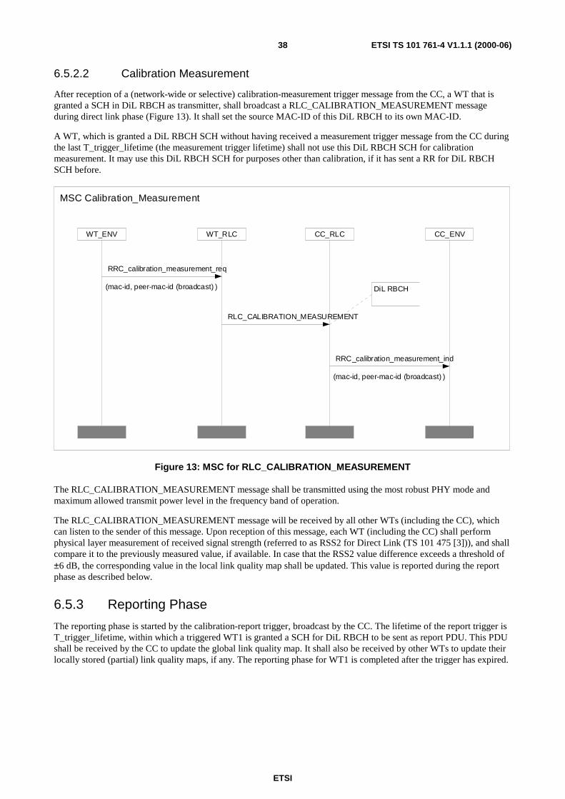
ETSI
ETSI TS 101 761-4 V1.1.1 (2000-06)38
6.5.2.2 Calibration Measurement
After reception of a (network-wide or selective) calibration-measurement trigger message from the CC, a WT that isgranted a SCH in DiL RBCH as transmitter, shall broadcast a RLC_CALIBRATION_MEASUREMENT messageduring direct link phase (Figure 13). It shall set the source MAC-ID of this DiL RBCH to its own MAC-ID.
A WT, which is granted a DiL RBCH SCH without having received a measurement trigger message from the CC duringthe last T_trigger_lifetime (the measurement trigger lifetime) shall not use this DiL RBCH SCH for calibrationmeasurement. It may use this DiL RBCH SCH for purposes other than calibration, if it has sent a RR for DiL RBCHSCH before.
CC_ENVCC_RLCWT_RLCWT_ENV
DiL RBCH
MSC Calibration_Measurement
RRC_calibration_measurement_ind
(mac-id, peer-mac-id (broadcast) )
RRC_calibration_measurement_req
(mac-id, peer-mac-id (broadcast) )
RLC_CALIBRATION_MEASUREMENT
Figure 13: MSC for RLC_CALIBRATION_MEASUREMENT
The RLC_CALIBRATION_MEASUREMENT message shall be transmitted using the most robust PHY mode andmaximum allowed transmit power level in the frequency band of operation.
The RLC_CALIBRATION_MEASUREMENT message will be received by all other WTs (including the CC), whichcan listen to the sender of this message. Upon reception of this message, each WT (including the CC) shall performphysical layer measurement of received signal strength (referred to as RSS2 for Direct Link (TS 101 475 [3])), and shallcompare it to the previously measured value, if available. In case that the RSS2 value difference exceeds a threshold of±6 dB, the corresponding value in the local link quality map shall be updated. This value is reported during the reportphase as described below.
6.5.3 Reporting Phase
The reporting phase is started by the calibration-report trigger, broadcast by the CC. The lifetime of the report trigger isT_trigger_lifetime, within which a triggered WT1 is granted a SCH for DiL RBCH to be sent as report PDU. This PDUshall be received by the CC to update the global link quality map. It shall also be received by other WTs to update theirlocally stored (partial) link quality maps, if any. The reporting phase for WT1 is completed after the trigger has expired.

ETSI
ETSI TS 101 761-4 V1.1.1 (2000-06)39
6.5.3.1 Calibration-Report Trigger:
The CC shall trigger the start of the reporting phase by broadcasting the RLC_CALIBRATION_REPORT_TRIGGERmessage using a downlink RBCH SCH (Figure 14). The report trigger shall indicate whether all WTs, or a set ofselected WTs shall report their calibration measurement results. In case that a set of WTs (up to three) is triggered, thecorresponding MAC-ID list shall be included in the trigger message.
CC_ENVCC_RLCWT_RLCWT_ENV
MSC Calibration_Report_Trigger
DL RBCH
RRC_calibration_report_trigger_req
( mac-id (broadcast),trigger-type,
mac-ids)
RRC_calibration_report_trigger_ind
( mac-id (broadcast),trigger-type,
mac-ids)
RLC_CALIBRATION_REPORT_TRIGGER
(trigger-type,mac-ids)
Figure 14: MSC for RLC_CALIBRATION_REPORT_TRIGGER
The RLC_CALIBRATION_REPROT_TRIGGER message shall be transmitted using the most robust PHY mode.
After calibration report trigger, the CC shall grant DiL RBCH resources to all, or a set of WTs to transmit calibrationreport PDUs in direct link. Only DiL RBCH SCHs granted within the lifetime of the report trigger of T_trigger_lifetimeshall be regarded as calibration report PDUs.
Table 8: RLC-CALIBRATION-REPORT-TRIGGER
RLC-CALIBRATION-REPORT-TRIGGER -ARG::= SEQUENCE {rlc-pdu-type RLC-HE-SCH-PDU-TYPE,extension-type EXTENSION-TYPE,trigger-type TRIGGER-TYPE,mac-ids MAC-IDS }
6.5.3.2 Calibration Report:
Depending on the number of calibration measurements performed, the CC may grant SCHs or LCHs to a triggered WTto send its reports. After reception of a (network-wide or selective) calibration-report trigger message from the CC, aWT that is granted a SCH or LCH in DiL RBCH as transmitter, shall broadcast aRLC_SHORT_CALIBRATION_REPORT or RLC_CALIBRATION_REPORT message during direct link phase(Figure 15). It shall set the source MAC-ID of this DiL RBCH to its own MAC-ID. In the case of SCH,RLC_SHORT_CALIBRATION_REPORT contains up to two reports. In the case of LCH,RLC_CALIBRATION_REPORT may contain up to 22 reports. The field number-of-reports describes the number ofactual reports contained in the current LCH PDU.
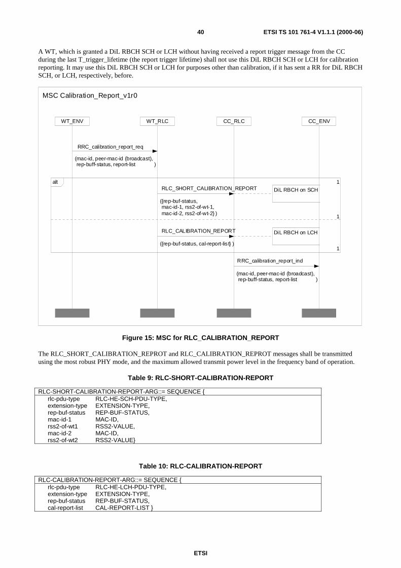
ETSI
ETSI TS 101 761-4 V1.1.1 (2000-06)40
A WT, which is granted a DiL RBCH SCH or LCH without having received a report trigger message from the CCduring the last T_trigger_lifetime (the report trigger lifetime) shall not use this DiL RBCH SCH or LCH for calibrationreporting. It may use this DiL RBCH SCH or LCH for purposes other than calibration, if it has sent a RR for DiL RBCHSCH, or LCH, respectively, before.
CC_ENVCC_RLCWT_RLCWT_ENV
DiL RBCH on LCH
DiL RBCH on SCH
1
1alt
1
MSC Calibration_Report_v1r0
RLC_CALIBRATION_REPORT
({rep-buf-status, cal-report-lis t} )
RLC_SHORT_CALIBRATION_REPORT
({rep-buf-status,mac-id-1, rss2-of-wt-1,mac-id-2, rss2-of-wt-2} )
RRC_calibration_report_ind
(mac-id, peer-mac-id (broadcast),rep-buff-status, report-list )
RRC_calibration_report_req
(mac-id, peer-mac-id (broadcast),rep-buff-status, report-list )
Figure 15: MSC for RLC_CALIBRATION_REPORT
The RLC_SHORT_CALIBRATION_REPROT and RLC_CALIBRATION_REPROT messages shall be transmittedusing the most robust PHY mode, and the maximum allowed transmit power level in the frequency band of operation.
Table 9: RLC-SHORT-CALIBRATION-REPORT
RLC-SHORT-CALIBRATION-REPORT-ARG::= SEQUENCE {rlc-pdu-type RLC-HE-SCH-PDU-TYPE,extension-type EXTENSION-TYPE,rep-buf-status REP-BUF-STATUS,mac-id-1 MAC-ID,rss2-of-wt1 RSS2-VALUE,mac-id-2 MAC-ID,rss2-of-wt2 RSS2-VALUE}
Table 10: RLC-CALIBRATION-REPORT
RLC-CALIBRATION-REPORT-ARG::= SEQUENCE {rlc-pdu-type RLC-HE-LCH-PDU-TYPE,extension-type EXTENSION-TYPE,rep-buf-status REP-BUF-STATUS,cal-report-list CAL-REPORT-LIST }

ETSI
ETSI TS 101 761-4 V1.1.1 (2000-06)41
Each WT shall arrange the measured RSS2 values according to their relative change since the last calibrationmeasurement. Those RSS2 values with the highest change shall be reported first. Depending on the granted resources,the WT transmits all or part of its reports. In case the WT could not report all RSS2 measurement values that havechanged by more than ±6 dB, it may indicate in the report PDU by setting the rep-buf-status bit that more resources arerequired.
From time to time, the CC may want to receive all RSS2 values from a WT. In this case the CC shall grant sufficientSCHs or LCHs for DiL RBCH to this WT, so that even those RSS2 values whose changes are below ±6 dB, can beincluded in the calibration report PDU.
The report list includes the MAC-ID of the measured WT and the corresponding RSS2 value.
NOTE: The received signal strength of the reports can also be used to check the local topology map.
6.5.4 Link Quality Map of the Network
Once all WTs have reported their measurement results, the CC creates and stores the link quality map of the network,which indicates the quality of connectivity between each WT pairs. The link quality map of a network with n associatedWTs (including the CC), can be represented by a matrix:
Table 11: Link quality map of the network
MAC-ID1 MAC-ID2 MAC-IDi … MAC-IDn
MAC-ID1 RSS2 1� 2 RSS2 1� i … RSS2 1� n
MAC-ID2 RSS2 2� 1 RSS2 2� i … RSS2 2� n
MAC-IDx RSS2 x� 1 RSS2 x� 2 … RSS2 x� n
… … … … … …
MAC-IDn RSS2 n� 1 RSS2 n� 2 RSS2 n� i …
RSS2 n�m represents the DiL received signal strength measured at WT n, when transmitted by WT m.
• A row corresponds to how a given WT receives all other WTs. RSS2 information contained in a row is gatheredas it is measured by the WT.
• A column corresponds to how a WT is received by all other WTs. RSS2 information contained in a column isgathered as it is broadcast to other WTs.
Each WT stores locally the relevant part of the map, i.e. the corresponding row and column. The CC shall store thecomplete link quality map of the network. The CC may assign a timer to each RSS2 value in the link quality map so asto handle partial reporting or some reports received in error. Timers are initialized by the CC when measurements areperformed.
The CC may distribute the link quality map of the network to a single or to all WTs in the network. A specific RLCPDU is defined for this purpose, called RLC_CALIBRATION_LINKQUALITYMAP. TheRLC_CALIBRATION_LINKQUALITYMAP may be send upon request of a WT(RLC_CALIBRATION_LINKQUALITYMAP_REQUEST) or without an explicit request from a WT.
NOTE: In the latter case the point in time or the period of the link quality map broadcast is out of the scope of thepresent document.
Figure 16 gives an overview of the distribution of the link quality map. Without an explicit request from a WT only thelower part of the figure is carried out.

ETSI
ETSI TS 101 761-4 V1.1.1 (2000-06)42
CC_ENVCC_RLCWT_RLCWT_ENV
DiL RBCH
MSC Calibration_LinkQualityMap
RRC_calibration_LINKQUALITYMAP_Request_cnf
( mac-id(broadcast),map-ext-ind,
complete-report-list)
RRC_calibration_LINKQUALITYMAP_Request_rsp
( mac-id(broadcast),map-ext-ind,
complete-report-list)
RLC_CALIBRATION_LINKQUALITYMAP_
REQUEST_ACK
( map-ext-ind,complete-report-list)
RRC_calibration_LINKQUALITYMAP_Request_ind
(mac-id,request-type, mac-id )
RRC_calibration_LINKQUALITYMAP_Request_req
(mac-id, request-type, mac-id )
RLC_CALIBRATION_LINKQUALITYMAP_REQUEST
(request-type, mac-id )
Figure 16: MSC for RLC_CALIBRATION_LINKQUALITYMAP_REQUEST andRLC_CALIBRATION_LINKQUALITYMAP
The RLC_CALIBRATION_LINKQUALITYMAP_REQUEST and RLC_CALIBRATION_LINKQUALITYMAPmessages shall be transmitted using the most robust PHY mode.
Table 12: RLC-CALIBRATION-LINKQUALITYMAP-REQUEST
RLC-CALIBRATION-LINKQUALITYMAP-REQUEST-ARG::= SEQUENCE {rlc-pdu-type RLC-HE-SCH-PDU-TYPE,extension-type EXTENSION-TYPE,mac-id MAC-ID,request-type REQUEST-TYPE }
Table 13: RLC-CALIBRATION-LINKQUALITYMAP
RLC-CALIBRATION-LINKQUALITYMAP -ARG::= SEQUENCE {rlc-pdu-type RLC-HE-LCH-PDU-TYPE,extension-type EXTENSION-TYPE,map-ext-ind MAP-EXT-IND,complete-report-list COMPLETE-REPORT-LIST }
Within the RLC_CALIBRATION_LINKQUALITYMAP_REQUEST a parameter called request-type indicates whetherthe whole map is requested or only a partial map. A partial map corresponds to a column in Table 11, which includes theRSS2 values with which all other WTs have received the RLC_CALIBRATION_MEASUREMENT PDU from the WTwith mac-id.

ETSI
ETSI TS 101 761-4 V1.1.1 (2000-06)43
To unify complete and partial quality map encoding, the link quality map shall be encoded by columns. This means thateach (partial) report consists of the MAC-ID of the WT that has sent RLC_CALIBRATION_MEASUREMENT, and Ntimes the MAC-ID, RSS2 value and the age of the measurement for each of the N receiving WTs. A complete report listis composed of several partial reports (for all sending WTs). An age of measurement field has been included to indicatewhen the RSS2 value has been updated for each of the receiving WTs. The field map-ext-ind (map-end, map-continue)indicates whether more RLC_CALIBRATION_LINKQUALITYMAP PDUs will follow, and can be used in the casethat the link quality map cannot be transmitted in a single LCH PDU.
The encoding of RLC_CALIBRATION_LINKQUALITYMAP is the same for partial and complete link quality maps,but partial RLC_CALIBRATION_LINKQUALITYMAP shall be transmitted on DL DCCH to the sender-WT of thereport whereas complete RLC_CALIBRATION_LINKQUALITYMAP shall be broadcast on DL RBCH.

ETSI
ETSI TS 101 761-4 V1.1.1 (2000-06)44
6.6 DLC User Connection Control
6.6.1 Fixed slot allocation for DM
peer_mac_id is themutlticast mac_id
source-mac-id is the mac-idof the multicast sender
The CC setup connectionswith all terminals that havejoined the group
CC initiated Sender initiated
n is the number ofjoined multicastreceivers
MSC Direct_Link_Multicast_Setup_ 1(1)
WT_ASSOCIATED_WITH_CC
MulticastGroupJoin
Direct_Link_Multicas t__Setup_Sender_init iated
loop <1, n> Direct_ Link_Multicast__Setup_CC_ initiated
MULTICAST_CONNECTION_ESTABLISHED
Direct_Link_Multicas t__Connect_completion
Figure 17: Overview of DiL Multicast Setup
6.6.2 Multicast in DiL phase
6.6.2.1 General
The Direct Link can also be used for multicast connections. DiL multicast without QoS negotiation is already supportedby documents TS 101 761-1 [1], TS 101 761-2 [2].

ETSI
ETSI TS 101 761-4 V1.1.1 (2000-06)45
A multicast connection is identified by three numbers:
• Destination MAC_ID, numbers from 224 to 254 shall be used;
• Source MAC_ID, mac_id of the WT that is the sender of this group;
• DLCC_ID=63 shall be used.
As is shown in Figure 17, the first action for a WT is to join the muticast group by using the RLC_GROUP_JOINmessage. Then the CC replies with a dynamically selected multicast MAC ID within the range {224, 254}. This MACID, in conjunction with DLCC ID=63, will be used as a unique identifier for the multicast group.
A multicast group that does not require QoS parameter negotiation shall start multicast immediately without performingthe DiL multicast setup procedure specified in the following subclauses. In this case, each WT of a multicast group canbecome the sender of this multicast group at any time. It just needs to send out a RR for DiL UMCH, in which it sets thedestination MAC ID to the assigned multicast MAC ID, the source MAC ID to its own MAC ID, and DLCC ID to 63.
Before a WT1 can become a sender of a multicast group which requires QoS parameter negotiation, it shall first run asender-initiated DM_Multicast_Setup procedure with the CC. Before the DM_Multicast_Setup procedure issuccessfully completed, the WT1 shall not begin to transmit data. After the multicast setup initiation by WT1, the CCshall forward the multicast setup request message to each multicast receiver WTx that has joined the multicast group.
The CC can also initiate a DM_Multicast_Setup even if it is not the sender, in that case it has also to send a multicastsetup request to the sender WT1. Then, the CC shall perform a multicast setup forwarding procedure for each receiverWTx of the multicast group. The setup request to the sender WT1 and the setup forwarding to each receiver WTx uses acommon procedure, which is the same as the setup forwarding procedure used in the sender-initiated case.
In both sender-initiated and CC-initiated cases, the CC shall send a RLC_DM_MC_CONNECT_COMPLETE messageto the sender WT1 after it has forwarded all setup request messages to all other WTs of the group. TheRLC_DM_MC_CONNECT_COMPLETE message shall be sent only when at least min-req-receivers receivers havepositively acknowledged the multicast setup request. min-required-receivers is a parameter in theRLC_DM_MC_SETUP message, which will be set by the initiating WT, or the CC.
Another parameter set by the initiating WT is the max_setup_time. This parameter is coded exponentially:
[ ]MacFrameswtsetupdmT timesetup _max_4___ =
After transmitting the first RLC_DM_MC_SETUP message to a receiver WTx, the CC starts the timer T_dm_setup_wt.If more than or equal to min_required_receivers WTs have completed the setup procedure until the timerT_dm_setup_wt expires, the multicast connection is established. That confirmation is given by the CC to the senderWT1 by sending it a RLC_DM_MC_CONNECT_COMPLETE message. Then, the sender WT1 is allowed to send datain the specified multicast DUC.
If a terminal responds to the CC after the connection setup has finished it is allowed to receive the multicast DUC,although the earlier data might be lost for this WT. If a terminal joins the group after the setup procedure is completed, itshall wait until the CC informs it of the ongoing multicast connection. The CC shall inform later joining WTx of theconnection parameters by performing the setup forwarding procedure for the joining receiver WTx.
The parameters of an established multicast connection can be modified by a DM_Multicast_Modify procedure. TheDM_Multicast_Release procedure is used to release an established multicast connection.
DiL multicast setup is mandatory for multicast groups which make use of Fixed Capacity Assignment specified inTS 101 761-1 [1] or Fixed Slot Allocation as specified in subclause 6.6.1 of the present document.
Referring to the following MSCs the CC can act as the multicast sender WT1, or as one of the multicast receivers WTx.In this case all multicast related RLC messages between this WT1 and the CC, or between this multicast receiver WTxand the CC, shall be exchanged internally in the CC device.
All multicast setup, modify and release procedures specified in the following shall use unicast DL DCCH and ULDCCH for message exchange between the CC and multicast sender WT1, and between the CC and a particular multicastreceiver WTx, respectively. As defined for CM, the MAC ID of the uplink and downlink unicast DCCH shall be alwaysset to the MAC ID of the WT, which sends or receives this DL or UL DCCH.

ETSI
ETSI TS 101 761-4 V1.1.1 (2000-06)46
6.6.2.2 DiL MULTICAST SETUP, WT-initiated
When a WT1 of a DiL multicast group wants to become a sender of this multicast group, it shall initiate this procedure ifthe connection requires QoS parameter negotiation. The CC and WT1 may negotiate e.g. FSA or FCA parameters.Referring to the following MSC (Figure 18), the source MAC ID is the MAC ID of WT1. This MAC ID is needed forthe CC to identify the sender WT1.
For exchanging the link parameters the initiating WT1 transmits a RLC_DM_MC_SETUP message to the CC. The CCshall respond by sending the RLC_DM_MC_CONNECT message which is acknowledged by the initiating WT1. In thismessage the CC can modify the QoS parameters proposed by the initiating WT1.
The direction parameter of the multicast duc-descriptor shall be set to simplex-forward for the multicast sender WT1,and set to simplex-backward for all multicast receivers WTx.
Figure 18: MSC Direct_Link_Multicast_Setup_WT_CC
Table 14: RLC-DM-MC-SETUP
RLC-DM-MC-SETUP-ARG::= SEQUENCE {rlc-pdu-type RLC-HE-LCH-PDU-TYPE,extension-type EXTENSION-TYPEpeer-mac-id MAC-ID,source-mac-id MAC-ID,cl-id CL-ID,duc-ext-ind BOOLEAN,min-req-receivers INTEGER(0..255),cl-conn-attr-length INTEGER(0..31),duc-descr-list DUC-DESCR-LIST,cl-common-attr CL-COMMON-ATTR }
The parameter source-mac-id is used to identify the sender WT1 in the case of a sender-initiated connection setup. In thecase of a CC-initiated connection setup this parameter is used to inform a WT1 that it is to become the sender.
CC_ENVCC_RLCWT1_RLCWT1_ENV
Associated
MSCDirect_Link_Multicast_Setup_Sender_initiated
RLC_DM_MC_SETUP
( {peer_mac_id,source_mac_id,cl_id,duc_ext_ind,min_req_receivers,cl_conn_attr_length,duc_descr_list,cl_common_attr} )
T_dm_mc_connect_cc
T_dm_mc_setup_wt
RLC_DM_MC_CONNECT_ACK
( {peer_mac_id,source_mac_id,cl_id,cl_conn_attr_length,dlcc_descr_list} )
DUC_dm_mc_connect_rsp
( {DUC-DM-MC-CONNECT-ACK-ARG})
RLC_DM_MC_CONNECT
( {peer_mac_id,source_mac_id,
cl_id,cl_conn_attr_length,
duc_descr_list} )
DUC_dm_mc_connect_ind
({DUC-DM-MC-CONNECT-ARG} )
DUC_dm_mc_connect_cnf
( {DUC-DM-MC-CONNECT-ACK-ARG})
DUC_dm_mc_setup_req
( {DUC-DM-MC-SETUP-ARG})
DUC_dm_mc_connect_req
({DUC-DM-MC-CONNECT-ARG} )
DUC_dm_mc_setup_ind
( {DUC-DM-MC-SETUP-ARG})
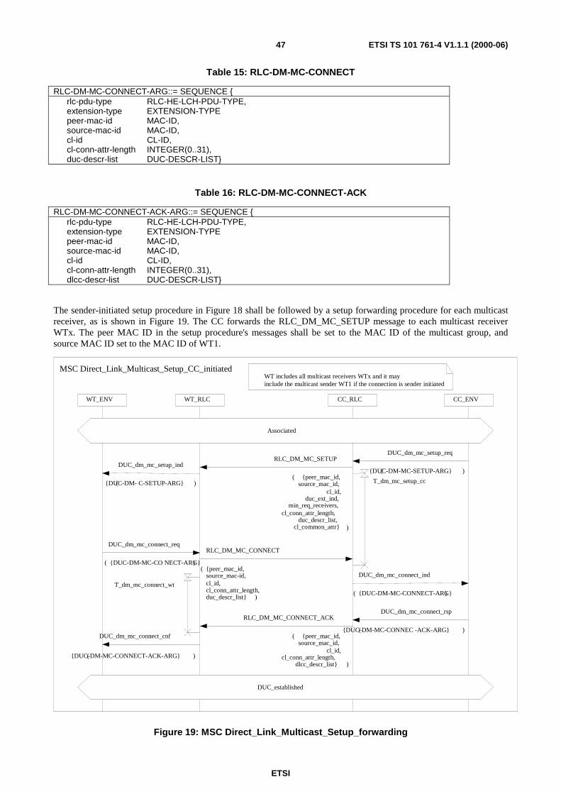
ETSI
ETSI TS 101 761-4 V1.1.1 (2000-06)47
Table 15: RLC-DM-MC-CONNECT
RLC-DM-MC-CONNECT-ARG::= SEQUENCE {rlc-pdu-type RLC-HE-LCH-PDU-TYPE,extension-type EXTENSION-TYPEpeer-mac-id MAC-ID,source-mac-id MAC-ID,cl-id CL-ID,cl-conn-attr-length INTEGER(0..31),duc-descr-list DUC-DESCR-LIST}
Table 16: RLC-DM-MC-CONNECT-ACK
RLC-DM-MC-CONNECT-ACK-ARG::= SEQUENCE {rlc-pdu-type RLC-HE-LCH-PDU-TYPE,extension-type EXTENSION-TYPEpeer-mac-id MAC-ID,source-mac-id MAC-ID,cl-id CL-ID,cl-conn-attr-length INTEGER(0..31),dlcc-descr-list DUC-DESCR-LIST}
The sender-initiated setup procedure in Figure 18 shall be followed by a setup forwarding procedure for each multicastreceiver, as is shown in Figure 19. The CC forwards the RLC_DM_MC_SETUP message to each multicast receiverWTx. The peer MAC ID in the setup procedure's messages shall be set to the MAC ID of the multicast group, andsource MAC ID set to the MAC ID of WT1.
WT includes all multicast receivers WTx and it mayinclude the multicast sender WT1 if the connection is sender initiated
WT_RLCWT_ENV CC_RLC CC_ENV
DUC_established
Associated
MSC Direct_Link_Multicast_Setup_CC_initiated
DUC_dm_mc_connect_req
( {DUC-DM-MC-CO NECT-ARG})
DUC_dm_mc_connect_rsp
({DUC-DM-MC-CONNEC -ACK-ARG} )DUC_dm_mc_connect_cnf
({DUC-DM-MC-CONNECT-ACK-ARG} )
DUC_dm_mc_connect_ind
( {DUC-DM-MC-CONNECT-ARG})
T_dm_mc_setup_cc
T_dm_mc_connect_wt
RLC_DM_MC_CONNECT_ACK
( {peer_mac_id,source_mac_id,
cl_id,cl_conn_attr_length,
dlcc_descr_list} )
RLC_DM_MC_CONNECT
( {peer_mac_id,source_mac-id,cl_id,cl_conn_attr_length,duc_descr_list} )
RLC_DM_MC_SETUP
( {peer_mac_id,source_mac_id,
cl_id,duc_ext_ind,
min_req_receivers,cl_conn_attr_length,
duc_descr_list,cl_common_attr} )
DUC_dm_mc_setup_ind
({DUC-DM- C-SETUP-ARG} )
DUC_dm_mc_setup_req
({DUC-DM-MC-SETUP-ARG} )
Figure 19: MSC Direct_Link_Multicast_Setup_forwarding

ETSI
ETSI TS 101 761-4 V1.1.1 (2000-06)48
The CC then waits for the multicast receivers to respond. If one or more multicast receivers do not respond withinmax_setup_time, the CC may retransmit the RLC_DM_MC_SETUP message to each of those multicast receivers.Further repetitions are also possible.
After min-req-receivers receivers have accepted the multicast setup within max-setup-time, the CC shall respond toWTx by sending RLC_DM_MC_CONNECT_ACK messages. Otherwise, it shall abort the multicast connection setupby performing a CC-initiated multicast release for each receiver WTx that is already involved in the setup procedure,and the sender WT1.
If at least min_required_receivers WTx respond positively within max-setup-time, which has been exchanged betweeninitiating WT1 and CC, the multicast connection is accepted by the CC. The CC transmits aRLC_DM_MC_CONNECT_COMPLETE message to the initiating WT1. The initiating WT1 shall respond with aRLC_DM_MC_CONNECT_COMPLETE_ACK message (Figure 20).
WT1_RLCWT1_ENV CC_RLC CC_ENV
Multicast_DUC_established
MSC Direct_Link_Multicast_Connect_completion
RLC_DM_MC_CONNECT_COMPLETE
( {peer-mac-id,source-mac-id,
dlcc-id-list})
RLC_DM_MC_CONNECT_COMPLETE_ACK
({peer-mac-id,source-mac-id})
DUC_dm_mc_conn_complete_rsp
(DUC-DM-MC-COMPLETE-ACK-ARG )
DUC_dm_mc_conn_complete_cnf
(DUC-DM-MC-COMPLETE-ACK-ARG )
DUC_dm_mc_conn_complete_req
( DUC-DM-COMPLETE-ARG)
T_dm_mc_connect_cmpt_ccDUC_dm_mc_conn_complete_ind
( DUC-DM-MC_COMPLETE-ARG)
Figure 20: MSC Direct_Link_Multicast_Setup_Completion
Table 17: RLC-DM-MC-CONNECT-COMPLETE
RLC-DM-MC-CONNECT-COMPLETE-ARG::= SEQUENCE {rlc-pdu-type RLC-HE-LCH-PDU-TYPE,extension-type EXTENSION-TYPEpeer-mac-id MAC-ID,source-mac-id MAC-ID,dlcc-id-list DLCC-ID-LIST}

ETSI
ETSI TS 101 761-4 V1.1.1 (2000-06)49
Table 18: RLC-DM-MC-CONNECT-COMPLETE-ACK
RLC-DM-MC-CONNECT-COMPLETE-ACK-ARG::= SEQUENCE {rlc-pdu-type RLC-HE-LCH-PDU-TYPE,extension-type EXTENSION-TYPEpeer-mac-id MAC-ID,source-mac-id MAC-ID}
6.6.2.3 DiL MULTICAST SETUP for a new joining WT
This clause describes the cases that a new WT has joined the group and is informed by the CC of the multicastconnection parameters.
The CC shall re-use the setup forwarding procedure depicted in Figure 19 after a new WT has joined the multicast groupusing the JOIN procedure to let the new WT know the MAC ID of the multicast sender and other connectionparameters. After this multicast setup procedure is completed, this new WT might not be able to receive the multicastdata. In this case, it may perform the DiL Power Control procedure for multicast/broadcast to request the multicastsender to increase the transmit power. No further action is specified, if the new WT still cannot decode the multicastdata correctly.
The multicast setup forwarding procedure for a new joining multicast receiver is transparent to the multicast sender.
6.6.2.4 DiL MULTICAST SETUP, CC initiated
This clause describes the case that a new multicast connection from a sender WT1 (also the CC may be the sender) tothe multicast group (also the CC may be member of this group) is to be established by the CC.
The CC-initiated multicast uses the procedure in Figure 19 for the multicast sender and all receivers. The CC shall firsttransmit a RLC_DM_MC_SETUP to the sender WT1, at this stage the sender can negociate parameters of theconnection with the CC. The peer_MAC_ID parameter in the RLC_DM_MC_SETUP message shall be set to the MAC-ID of the multicast group. The sender WT1 is informed that it is to become the sender by looking at the source_mac_idfield in the RLC_DM_MC_SETUP message, which is set to the MAC ID of WT1.
The sender WT1 shall respond with a RLC_DM_MC_CONNECT and the CC shall send the acknowledgement toconfirm parameters. Then the CC shall repeat the setup forwarding procedure in Figure 19 for each joined multicastreceiver WTx.
The CC then waits for WTs to respond. If one or more multicast receiver WTs does not respond within max_setup_time,the CC may retransmit the RLC_DM_MC_SETUP message using a downlink unicast DCCH. Further repetitions arealso possible. The multicast sender WT1 shall respond positively within max_setup_time. Otherwise, the CC-initiatedDiL_Multicast_Setup procedure fails.
If at least min_required_receivers WTs (the sender excluded) of the multicast group respond within max_setup_time tothe RLC_DM_MC_SETUP message, the multicast connection is accepted by the CC. A negotiation of max_setup_timeis not needed, if the CC is the sender of the multicast connection. If for any reason the multicast setup fails, the CC shallabort the multicast setup procedure by performing a CC-initiated multicast release for the multicast sender and eachmulticast receiver already involved in the setup procedure.

ETSI
ETSI TS 101 761-4 V1.1.1 (2000-06)50
If the sender and min_req_receivers receivers have accepted the multicast setup, the Multicast Setup Completionprocedure in Figure 20 shall be finally performed. The CC shall transmit a RLC_DM_MC_CONNECT_COMPLETEmessage to the sender WT1 or to itself (if CC is sender), which shall be responded by aRLC_DM_MC_CONNECT_COMPLETE_ACK message.
6.6.2.5 MODIFY MULTICAST
The modification of the multicast connection characteristics can be sender-initiated or CC-initiated. If it is sender-initiated, the multicast sender WT1 shall send a RLC_DM_MC_MODIFY_REQ to the CC. This triggers the CC toperform multicast modify by sending RLC_DM_MC_MODIFY to the multicast sender WT1 (Figure 21) and to each ofthe multicast receivers WTx (Figure 22). The RLC_DM_MC_MODIFY contains a parameter field start-mac-frame,which tells all WTs when the modified multicast shall start. If it is CC-initiated, the CC shall perform the multicastmodify procedure without the request from the multicast sender. In this case, the procedure in Figure 22 shall alsoperformed for the multicast sender.
A timer T_rsp is set similar to the multicast setup procedure. If not all WTs have responded by sending aRLC_DM_MC_MODIFY_ACK until the timer expires the CC shall retransmit the RLC_DM_MC_MODIFY messageon DL DCCH to each of the concerned WTs.
The Multicast Setup Completion procedure shall not be used in case of modifying a multicast DUC.
The connection parameters are changed after all WTs of the multicast group have responded or all repetitions to the notresponding WTs have finished.
If the sender does not accept the RLC_DM_MC_MODIFY message from the CC, the CC shall release the multicastconnection for all involved WTs. If one or more multicast receiver does not accept the RLC_DM_MC_MODIFYmessage from the CC, the CC shall release the connection for these receivers. In the latter case it shall only release themulticast connection for all other WTs (including the sender), if the number of the remaining receivers is less thanmin_required_receivers.
The exact start point to change the multicast connection is given by the start-mac-frame parameter, which is sent fromthe CC to all multicast WTs. start-mac-frame is the absolute MAC Frame number as determined by the MAC FrameCounter in the BCCH. To overcome the 4 bit limitation of the MAC Frame Counter parameter in BCCH, start-mac-frame is furthermore offset by a MAC Frame Cycle parameter, which gives the number, the MAC Frame Counter valuerepeats in BCCH after the reception of the RLC_DM_MC_MODIFY message (1 repetition corresponds to 16 MACframes). The reference for the offset is the MAC frame the RLC_DM_MC_MODIFY PDU is received. That means thatthe RLC instance shall know in which MAC frame it received the RLC_DM_MC_MODIFY message in order todetermine the right MAC frame to change the multicast connection. The CC should set start_mac_frame sufficiently lateto allow all WTs to be prepared for this change.
start_mac_frame is 16 bits long. Its 4 MSB are used to encode the MAC Frame Counter value, and its 12 LSB are usedto encode the MAC Frame Cycle value. Either coding is in binary. With this length of the start_mac_frame parameterthe maximum time between the RLC_DM_MC_MODIFY PDU and the multicast connection change is 131 seconds.
EXAMPLE: start_mac_frame = 0010 000000000001The MAC frame to change the multicast connection is the second time (because of offset =000000000001) the MAC Frame Counter in the BCCH shows the value 0010 after the reception of theRLC_DM_MC_MODIFY PDU.
If a multicast connection is used for FSA, the start_mac_frame value in the RLC_DM_MC_MODIFY message shall beequal to the start-mac-frame value in the FSA-RG parameter, which is also included in RLC_DM_MC_MODIFY.
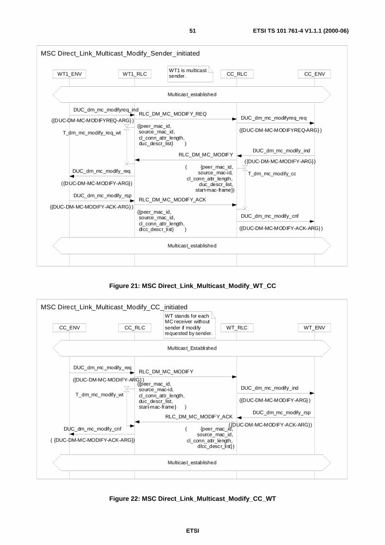
ETSI
ETSI TS 101 761-4 V1.1.1 (2000-06)51
WT1_RLC CC_RLCWT1_ENV CC_ENVWT1 is multicastsender.
Multicast_established
Multicast_established
MSC Direct_Link_Multicast_Modify_Sender_initiated
DUC_dm_mc_modify_req
({DUC-DM-MC-MODIFY-ARG})
DUC_dm_mc_modifyreq_ind
({DUC-DM-MC-MODIFYREQ-ARG} )
DUC_dm_mc_modify_rsp
({DUC-DM-MC-MODIFY-ACK-ARG} )
DUC_dm_mc_modify_ind
({DUC-DM-MC-MODIFY-ARG})RLC_DM_MC_MODIFY
( {peer_mac_id,source_mac-id,
cl_conn_attr_length,duc_descr_list,
start-mac-frame})
DUC_dm_mc_modify_cnf
({DUC-DM-MC-MODIFY-ACK-ARG} )
T_dm_mc_modify_cc
T_dm_mc_modify_req_wt
DUC_dm_mc_modifyreq_req
({DUC-DM-MC-MODIFYREQ-ARG} )
RLC_DM_MC_MODIFY_ACK
({peer_mac_id,source_mac_id,cl_conn_attr_length,dlcc_descr_list} )
RLC_DM_MC_MODIFY_REQ
({peer_mac_id,source_mac_id,cl_conn_attr_length,duc_descr_list} )
Figure 21: MSC Direct_Link_Multicast_Modify_WT_CC
WT stands for eachMC receiver withoutsender if modifyrequested by sender.
CC_RLC WT_RLCCC_ENV WT_ENV
Multicast_established
Multicast_Established
MSC Direct_Link_Multicast_Modify_CC_initiated
RLC_DM_MC_MODIFY
({peer_mac_id,source_mac-id,cl_conn_attr_length,duc_descr_list,start-mac-frame} )
RLC_DM_MC_MODIFY_ACK
( {peer_mac_id,source_mac_id,
cl_conn_attr_length,dlcc_descr_list})
DUC_dm_mc_modify_req
({DUC-DM-MC-MODIFY-ARG} )
DUC_dm_mc_modify_ind
({DUC-DM-MC-MODIFY-ARG} )
DUC_dm_mc_modify_rsp
({DUC-DM-MC-MODIFY-ACK-ARG})
T_dm_mc_modify_wt
DUC_dm_mc_modify_cnf
( {DUC-DM-MC-MODIFY-ACK-ARG})
Figure 22: MSC Direct_Link_Multicast_Modify_CC_WT
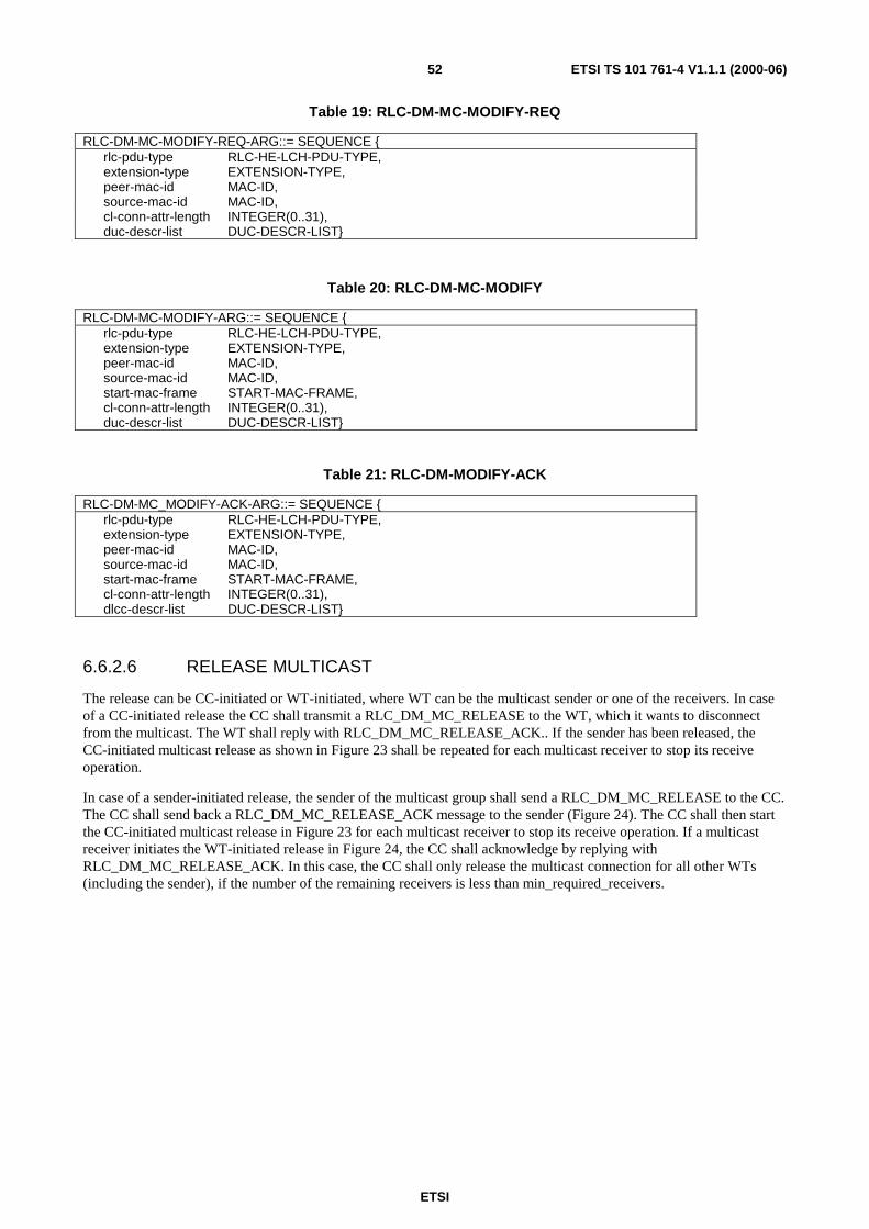
ETSI
ETSI TS 101 761-4 V1.1.1 (2000-06)52
Table 19: RLC-DM-MC-MODIFY-REQ
RLC-DM-MC-MODIFY-REQ-ARG::= SEQUENCE {rlc-pdu-type RLC-HE-LCH-PDU-TYPE,extension-type EXTENSION-TYPE,peer-mac-id MAC-ID,source-mac-id MAC-ID,cl-conn-attr-length INTEGER(0..31),duc-descr-list DUC-DESCR-LIST}
Table 20: RLC-DM-MC-MODIFY
RLC-DM-MC-MODIFY-ARG::= SEQUENCE {rlc-pdu-type RLC-HE-LCH-PDU-TYPE,extension-type EXTENSION-TYPE,peer-mac-id MAC-ID,source-mac-id MAC-ID,start-mac-frame START-MAC-FRAME,cl-conn-attr-length INTEGER(0..31),duc-descr-list DUC-DESCR-LIST}
Table 21: RLC-DM-MODIFY-ACK
RLC-DM-MC_MODIFY-ACK-ARG::= SEQUENCE {rlc-pdu-type RLC-HE-LCH-PDU-TYPE,extension-type EXTENSION-TYPE,peer-mac-id MAC-ID,source-mac-id MAC-ID,start-mac-frame START-MAC-FRAME,cl-conn-attr-length INTEGER(0..31),dlcc-descr-list DUC-DESCR-LIST}
6.6.2.6 RELEASE MULTICAST
The release can be CC-initiated or WT-initiated, where WT can be the multicast sender or one of the receivers. In caseof a CC-initiated release the CC shall transmit a RLC_DM_MC_RELEASE to the WT, which it wants to disconnectfrom the multicast. The WT shall reply with RLC_DM_MC_RELEASE_ACK.. If the sender has been released, theCC-initiated multicast release as shown in Figure 23 shall be repeated for each multicast receiver to stop its receiveoperation.
In case of a sender-initiated release, the sender of the multicast group shall send a RLC_DM_MC_RELEASE to the CC.The CC shall send back a RLC_DM_MC_RELEASE_ACK message to the sender (Figure 24). The CC shall then startthe CC-initiated multicast release in Figure 23 for each multicast receiver to stop its receive operation. If a multicastreceiver initiates the WT-initiated release in Figure 24, the CC shall acknowledge by replying withRLC_DM_MC_RELEASE_ACK. In this case, the CC shall only release the multicast connection for all other WTs(including the sender), if the number of the remaining receivers is less than min_required_receivers.

ETSI
ETSI TS 101 761-4 V1.1.1 (2000-06)53
WT includes allmult icast receivers and may include themulticast sender in case of CC initiated release
WT_RLCWT_ENV CC_RLC CC_ENV
MSC Direct_Link_Multicast_Release_CC_initiated
DUC_dm_mc_release_cnf
({DUC-DM-MC-RELEASE-ARG} )
DUC_dm_mc_release_rsp
({DUC-DM-MC-RELEASE-ARG} )
DUC_dm_mc_release_ind
( {DUC-DM-MC-RELEASE-ARG})
DUC_dm_mc_release_req
( {DUC-DM-MC-RELEASE-ARG})
RLC_DM_MC_RELEASE_ACK
({peer_mac_id,source_mac-id,dlcc_id_list} )
RLC_DM_MC_RELEASE
( {peer_mac_id,source_mac_id,
dlcc_id_list,release_cause})
T_dm_mc_release_cc
Figure 23: MSC Direct_Link_Multicast_Release_CC_WT
WT_RLC CC_RLCWT_ENV CC_ENV
Multicast_established
Associated
MSC Direct_Link_Multicast_Release_WT_initiated
T_dm_mc_release_wt
DUC_dm_mc_release_rsp
({DUC-DM-MC-RELEASE-ARG} )
DUC_dm_mc_release_cnf
({DUC-DM-MC-RELEASE-ARG} )
DUC_dm_mc_release_ind
( {DUC-DM-MC-RELEASE-ARG})
DUC_dm_mc_release_req
( {DUC-DM-MC-RELEASE-ARG})
RLC_DM_MC_RELEASE_ACK
({peer_mac_id,source_mac-id,
dlcc_id_list} )
RLC_DM_MC_RELEASE
( {peer_mac_id,source_mac_id,dlcc_id_list,release_cause})
Figure 24: MSC Direct_Link_Multicast_Release_WT_CC

ETSI
ETSI TS 101 761-4 V1.1.1 (2000-06)54
Table 22: RLC-DM-MC-RELEASE
RLC-DM-MC-RELEASE-ARG::= SEQUENCE {rlc-pdu-type RLC-HE-LCH-PDU-TYPE,extension-type EXTENSION-TYPE,peer-mac-id MAC-ID,source-mac-id MAC-ID,dlcc-id-list DLCC-ID-LIST,release-cause RELEASE-CAUSE}
Table 23: RLC- DM-MC- RELEASE-ACK
RLC-DM-MC-RELEASE-ACK-ARG::= SEQUENCE {rlc-pdu-type RLC-HE-LCH-PDU-TYPE,extension-type EXTENSION-TYPE,peer-mac-id MAC-ID,source-mac-id MAC-ID,dlcc-id-list DLCC-ID-LIST}
6.7 Dynamic CC SelectionThe dynamic CC Selection ensures that within one radio cell or subnet only one CC is established. It is performed in adecentralized and autonomous way by each CC-capable device. The selection does not take into account the bestposition or the best capabilities of a CC-capable device because the necessary measurements are not available at thisstage. The CC is selected at random based on a contention process. However, the user can prevent an unfavourablylocated CC-capable device from being the CC by disabling this CC-capable device to participate in the CC selectionprocess. All CC-capable H/2–HDs shall support dynamic CC selection. Besides, all CC-capable H/2-HDs shall indicateto the user by an implementation specific means whether they are in the CC selection phase, or acting as the CC.
6.7.1 Principle
Each CC-capable device first tries to become a WT. The first step is to scan all available frequencies for already runningCCs (initial scanning process, see 6.7.2). If no CC has been found or association to the CCs is not possible (e.g. it is theCC of the neighbour or a CC/AP without HE capability) each CC-capable device shall try to become a CC byperforming the CC Selection protocol. Each CC-capable shall also have a user interface, which enables the user todisable the CC Selection function, if the corresponding CC-capable device is to be excluded from the CC selectionprocess. A CC-capable device with disabled CC Selection function shall only be able to act as a basic WT.
In order to prevent multiple CC-capable devices from becoming CC, a CC collision resolution, i.e. the CC Selectionprotocol, is performed. The basic idea is that each CC-capable device transmits a "Probing Beacon" from time to timeand senses the channel in between. The Probing Process, i.e. transmitting of Probing Beacons and sensing the ProbingChannel to detect beacons from other devices, is interrupted for frequency scanning phases in which all other availablefrequencies are scanned for another CC-capable device. Each CC-capable device which senses a "Probing Beacon"withdraws from the CC Selection, performs a back-off and starts with the initial scanning process again. This may resultin a new CC Selection process.
After a predefined time the CC-capable device which has not sensed anything survives and becomes CC. Of course it isnot possible to resolve all collisions with this protocol. There is still a residual collision probability.
6.7.2 Initial Scanning Process
The scanning of frequency channels is not defined in the present document. For detection and selection of a CC it isnecessary to define some minimum requirements on the scanning process.
In order to find a CC the initial frequency scanning is performed first, e.g. if a H/2-HD is powered on. The CC selectionprocess is started only in the case no CC has been found.
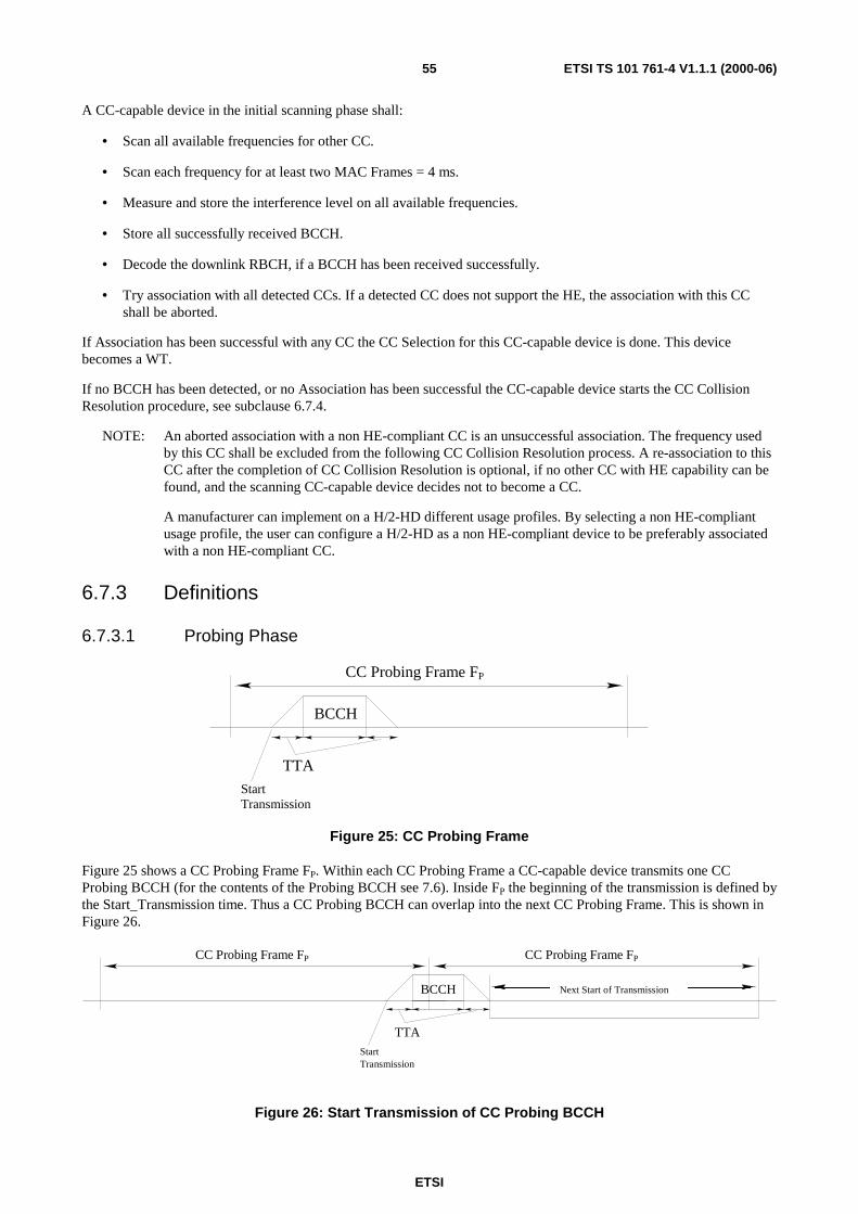
ETSI
ETSI TS 101 761-4 V1.1.1 (2000-06)55
A CC-capable device in the initial scanning phase shall:
• Scan all available frequencies for other CC.
• Scan each frequency for at least two MAC Frames = 4 ms.
• Measure and store the interference level on all available frequencies.
• Store all successfully received BCCH.
• Decode the downlink RBCH, if a BCCH has been received successfully.
• Try association with all detected CCs. If a detected CC does not support the HE, the association with this CCshall be aborted.
If Association has been successful with any CC the CC Selection for this CC-capable device is done. This devicebecomes a WT.
If no BCCH has been detected, or no Association has been successful the CC-capable device starts the CC CollisionResolution procedure, see subclause 6.7.4.
NOTE: An aborted association with a non HE-compliant CC is an unsuccessful association. The frequency usedby this CC shall be excluded from the following CC Collision Resolution process. A re-association to thisCC after the completion of CC Collision Resolution is optional, if no other CC with HE capability can befound, and the scanning CC-capable device decides not to become a CC.
A manufacturer can implement on a H/2-HD different usage profiles. By selecting a non HE-compliantusage profile, the user can configure a H/2-HD as a non HE-compliant device to be preferably associatedwith a non HE-compliant CC.
6.7.3 Definitions
6.7.3.1 Probing Phase
BCCH
TTA
CC Probing Frame FP
StartTransmission
Figure 25: CC Probing Frame
Figure 25 shows a CC Probing Frame FP. Within each CC Probing Frame a CC-capable device transmits one CCProbing BCCH (for the contents of the Probing BCCH see 7.6). Inside FP the beginning of the transmission is defined bythe Start_Transmission time. Thus a CC Probing BCCH can overlap into the next CC Probing Frame. This is shown inFigure 26.
BCCH
TTA
StartTransmission
CC Probing Frame FPCC Probing Frame FP
Next Start of Transmission
Figure 26: Start Transmission of CC Probing BCCH
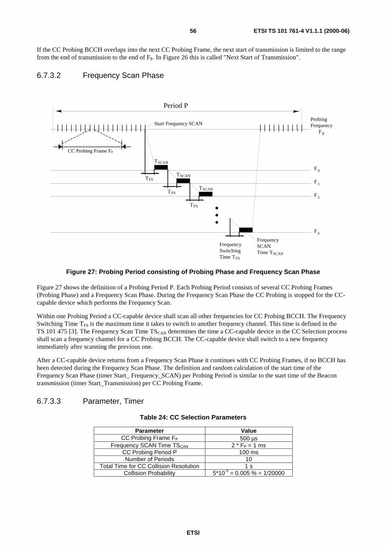
ETSI
ETSI TS 101 761-4 V1.1.1 (2000-06)56
If the CC Probing BCCH overlaps into the next CC Probing Frame, the next start of transmission is limited to the rangefrom the end of transmission to the end of FP. In Figure 26 this is called "Next Start of Transmission".
6.7.3.2 Frequency Scan Phase
F P
F 0
F 2
F n
F 1
TFS
TFS
TFS
TFS
TSCAN
TSCAN
TSCAN
TSCAN
Period P
ProbingFrequency
FrequencySwitchingTime
FrequencySCANTime
Start Frequency SCAN
CC Probing Frame FP
Figure 27: Probing Period consisting of Probing Phase and Frequency Scan Phase
Figure 27 shows the definition of a Probing Period P. Each Probing Period consists of several CC Probing Frames(Probing Phase) and a Frequency Scan Phase. During the Frequency Scan Phase the CC Probing is stopped for the CC-capable device which performs the Frequency Scan.
Within one Probing Period a CC-capable device shall scan all other frequencies for CC Probing BCCH. The FrequencySwitching Time TFS is the maximum time it takes to switch to another frequency channel. This time is defined in theTS 101 475 [3]. The Frequency Scan Time TSCAN determines the time a CC-capable device in the CC Selection processshall scan a frequency channel for a CC Probing BCCH. The CC-capable device shall switch to a new frequencyimmediately after scanning the previous one.
After a CC-capable device returns from a Frequency Scan Phase it continues with CC Probing Frames, if no BCCH hasbeen detected during the Frequency Scan Phase. The definition and random calculation of the start time of theFrequency Scan Phase (timer Start_ Frequency_SCAN) per Probing Period is similar to the start time of the Beacontransmission (timer Start_Transmission) per CC Probing Frame.
6.7.3.3 Parameter, Timer
Table 24: CC Selection Parameters
Parameter ValueCC Probing Frame FP 500 µs
Frequency SCAN Time TSCAN 2 * FP = 1 msCC Probing Period P 100 msNumber of Periods 10
Total Time for CC Collision Resolution 1 sCollision Probability 5*10-5 = 0.005 % = 1/20000
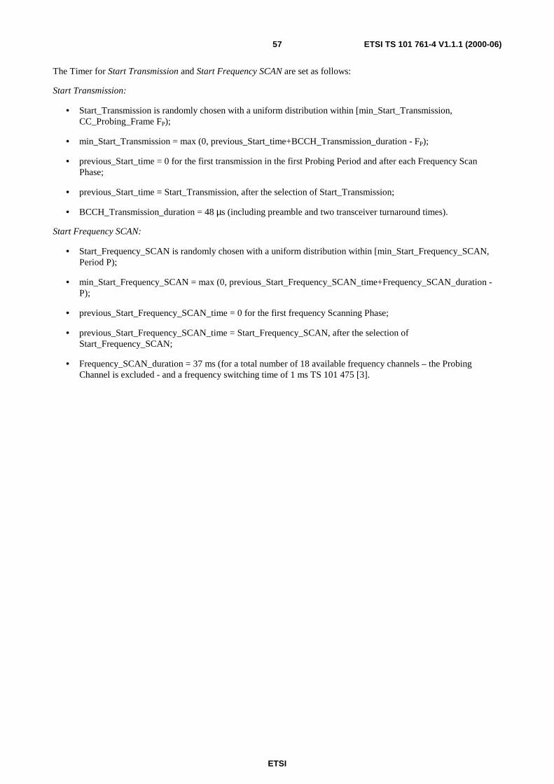
ETSI
ETSI TS 101 761-4 V1.1.1 (2000-06)57
The Timer for Start Transmission and Start Frequency SCAN are set as follows:
Start Transmission:
• Start_Transmission is randomly chosen with a uniform distribution within [min_Start_Transmission,CC_Probing_Frame FP);
• min_Start_Transmission = max (0, previous_Start_time+BCCH_Transmission_duration - FP);
• previous_Start_time = 0 for the first transmission in the first Probing Period and after each Frequency ScanPhase;
• previous_Start_time = Start_Transmission, after the selection of Start_Transmission;
• BCCH_Transmission_duration = 48 µs (including preamble and two transceiver turnaround times).
Start Frequency SCAN:
• Start_Frequency_SCAN is randomly chosen with a uniform distribution within [min_Start_Frequency_SCAN,Period P);
• min_Start_Frequency_SCAN = max (0, previous_Start_Frequency_SCAN_time+Frequency_SCAN_duration -P);
• previous_Start_Frequency_SCAN_time = 0 for the first frequency Scanning Phase;
• previous_Start_Frequency_SCAN_time = Start_Frequency_SCAN, after the selection ofStart_Frequency_SCAN;
• Frequency_SCAN_duration = 37 ms (for a total number of 18 available frequency channels – the ProbingChannel is excluded - and a frequency switching time of 1 ms TS 101 475 [3].

ETSI
ETSI TS 101 761-4 V1.1.1 (2000-06)58
6.7.4 Protocol
If no Association has been successful the CC-capable device shall choose one appropriate frequency channel. Thisfrequency channel is called CC Probing frequency.
The CC-capable device shall:
- Maintain a CC Probing Frame timer.
- Maintain a Start_Transmission timer.
- Maintain a CC Probing Period timer.
- Maintain a Start_Frequency_SCAN timer.
- Maintain a Period counter.
- Select a CC Probing BCCH transmission start time (Start_Transmission) each time the CC Probing Frametimer expires, or after the completion of the Frequency Scan Phase, if no BCCH has been detected; Set theCC Probing Frame Timer to FP.
- Select a frequency scanning start time (Start_Frequency_SCAN) each time the CC Probing Period timerexpires, set the CC Probing Period Timer to P and increase the Period_Counter by one.
- Transmit a CC Probing BCCH, if the CC Probing BCCH transmission start time is reached.
- Stop CC Probing and Start the frequency scanning procedure, if the frequency scanning start time is reached.
- Sense each frequency channel excluding the last Probing Frequency for other Probing BCCH.
- Stop the CC Selection Procedure and start a back-off of (1 s), if a Probing BCCH or a regular BCCH isreceived successfully. All timers are stopped. After the back-off has expired the CC-capable device startsagain with the initial scanning process trying to find a CC in operation and to associate to it, see subclause6.7.2. If no association is possible the CC Selection Protocol is performed again.
- Start CC operation, if Period_Counter = Number of Periods.
6.7.4.1 Frequency scanning
During the frequency scanning each frequency channel except the CC Probing frequency channel is scanned for CCProbing BCCH. The order of the frequency channels is randomly chosen. The selection procedure has to ensure thateach frequency is scanned once per Frequency SCAN.
Each frequency is scanned for 1 ms. If no BCCH has been detected after 1 ms the CC-capable device switches to thenext frequency. If no more frequencies have to be scanned in the current Period, the CC-capable device continues withCC Probing Frames.
6.8 CC Responsibility HandoverThe CC Responsibility Handover is necessary in case that the current CC is no longer able or intended to carry the CCresponsibility for the subnet. Reasons for a CC Responsibility Handover, that are out of the scope of the presentdocument, can be e.g. switch off of the WT currently carrying the CC responsibility, a bad connectivity of the currentCC, power constraints of the CC, etc. Only old CC-initiated CC Handover is considered in the present document.
The CC Responsibility Handover protocol guarantees a soft handover, in which case all DiL connections are maintainedduring and after the handover process. The handover is transparent to the network and to the other WTs as far as DiLconnections are concerned. The same applies to the user plane of the two terminals involved in the CC ResponsibilityHandover. The old CC becomes a WT and keeps its own DiL connections. All connections in CM are neverthelessreleased during CC Responsibility Handover. The CC Responsibility Handover concerns mainly MAC control and RLCinstances of the control plane of the current CC.
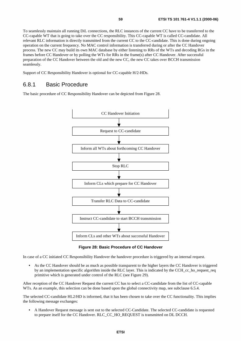
ETSI
ETSI TS 101 761-4 V1.1.1 (2000-06)59
To seamlessly maintain all running DiL connections, the RLC instances of the current CC have to be transferred to theCC-capable WT that is going to take over the CC responsibility. This CC-capable WT is called CC-candidate. Allrelevant RLC information is directly transmitted from the current CC to the CC-candidate. This is done during ongoingoperation on the current frequency. No MAC control information is transferred during or after the CC Handoverprocess. The new CC may build its own MAC database by either listening to RRs of the WTs and decoding RGs in theframes before CC Handover or by polling the WTs for RRs in the frame(s) after CC Handover. After successfulpreparation of the CC Handover between the old and the new CC, the new CC takes over BCCH transmissionseamlessly.
Support of CC Responsibility Handover is optional for CC-capable H/2-HDs.
6.8.1 Basic Procedure
The basic procedure of CC Responsibility Handover can be depicted from Figure 28.
CC Handover Initiation
Request to CC-candidate
Inform all WTs about forthcoming CC Handover
Stop RLC
Inform CLs which prepare for CC Handover
Transfer RLC Data to CC-candidate
Instruct CC-candidate to start BCCH transmission
Inform CLs and other WTs about successful Handover
Figure 28: Basic Procedure of CC Handover
In case of a CC initiated CC Responsibility Handover the handover procedure is triggered by an internal request.
• As the CC Handover should be as much as possible transparent to the higher layers the CC Handover is triggeredby an implementation specific algorithm inside the RLC layer. This is indicated by the CCH_cc_ho_request_reqprimitive which is generated under control of the RLC (see Figure 29).
After reception of the CC Handover Request the current CC has to select a CC-candidate from the list of CC-capableWTs. As an example, this selection can be done based upon the global connectivity map, see subclause 6.5.4.
The selected CC-candidate HL2/HD is informed, that it has been chosen to take over the CC functionality. This impliesthe following message exchanges:
• A Handover Request message is sent out to the selected CC-Candidate. The selected CC-candidate is requestedto prepare itself for the CC Handover. RLC_CC_HO_REQUEST is transmitted on DL DCCH.

ETSI
ETSI TS 101 761-4 V1.1.1 (2000-06)60
• The CC-candidate informs its RLC environment about the CC Handover Request by a CC Handover Indication.
• The RLC environment of the CC-candidate answers with a CC Handover Response.
• Then the selected CC-candidate WT acknowledges that it is prepared for the CC Handover. ThisRLC_CC_HO_ACK PDU is transmitted on UL DCCH.
The next step consists in informing all WTs about the forthcoming CC Handover. Sleeping WTs are not woken up.Instead, the sleeping intervals of these WTs are transferred together with the other RLC data to the CC-candidate in alater stage of the procedure (see below).
• The CC sends out a broadcast message on DL RBCH to inform all WTs about the forthcoming CC ResponsibilityHandover (RLC_CC_HO_NOTIFY). Even CC Handover is optional for CC-capable devices, theRLC_CC_HO_NOTIFY shall be supported by all H/2-HDs.
In response, the RLC entities of all WTs in the subnet are stopped. This means that no new Association, DUC Set-up/modify/release, power saving and DFS requests are started. The RLC entities of the WTs are set into a special stateRLC_Stopped_WT which only occurs during CC Handover.
• At the same time all ongoing Association, DUC Set-up/modify/release and power saving requests are aborted bythe current CC.
The RLC entities within the CC are set into the RLC_Stopped state. New requests are not processed by the CC anymore. During CC Handover no Association, DUC Set-up/Modify, Sleep or DFS request is possible to ease theoperation.
The fifth step in Figure 28 concerns the influence of the CC Handover on the higher layers, which may have to preparefor the CC Handover.
• After the positive acknowledgement of the CC-candidate the current CC sends out a CCH_start_cl_ho_indprimitive to the environment. This primitive may be used by the CLs as information of the forthcoming CCHandover.
After reception of the CCH_start_cl_ho_ind the CLs may prepare themselves for the CC Responsibility Handover, ifthis is necessary. They may e.g. perform a CL handover, if the current CC also contains a centralized decision makingentity and database in the respective CL. It is up to the CLs of the old CC to inform the other WTs (including the CC-candidate) on CL level about the ongoing CC Handover on RLC level, if necessary. The main part of the CC Handoverprocedure on RLC level, the transmission of the RLC data to the CC-candidate, may not be started unless the CLprocedures are finished.
• After a CCH_start_cl_ho_rsp primitive is received from the environment, all connections in CM are released bythe CC.
DiL connections relayed by the current CC are kept. They are only released in case that the CC is leaving the network(e.g. switch-off).
• Then the transfer of data, states and timers of the RLC to the CC-candidate is started by a CCH_start_cc_reqprimitive from the RLC environment. For this purpose DL DCCH is used between the CC and the CC-candidate(ordinary RLC operation). The RLC instances in the new CC are set to the same state as in the old CC. For adetailed description of the data transfer see subclauses 6.8.3 and 7.8.
• The CC data PDUs are transmitted by means of a "Go-back-n" ARQ mechanism. A certain number ofRLC_TRANS_CC_DATA PDUs are acknowledged by the CC-candidate with aRLC_TRANS_CC_DATA_ACK PDU on UL DCCH.
ETSI
ETSI TS 101 761-4 V1.1.1 (2000-06)61
The CC-candidate is now ready to take over the CC functionality. To enable a smooth handover, the old CC informs thenew CC when to start with a BCCH transmission. This is done by a handshake message:
• The current CC sends a RLC_START_CC message to the CC-candidate using DL DCCH and including anindication when to start with BCCH transmission (start-mac-frame). The parameter start-mac-frame gives theexact MAC Frame the new CC shall start CC operation. start-mac-frame is the absolute MAC Frame number asdetermined by the MAC Frame Counter in the BCCH. To overcome the 4 bit limitation of the MAC FrameCounter parameter in BCCH, Start MAC Frame is furthermore offset by a MAC Frame Cycle parameter, whichgives the number, the MAC Frame Counter value repeats in BCCH after the reception of the Start CC message (1repetition corresponds to 16 MAC frames). The reference for the offset is the MAC frame the RLC_Start_CCPDU is received. That means that the RLC instance shall know in which MAC frame it received theRLC_Start_CC in order to determine the right MAC frame to start CC operation. The CC-candidate shall be ableto start the CC operation at latest 2 MAC frames after the arrival of the RLC_Start_CC message.
Start-mac-frame is 16 bits long. Its 4 MSB are used to encode the MAC Frame Counter value, and its 12 LSB are usedto encode the MAC Frame Cycle value. Either coding is in binary. With this length of the start-mac-frame parameter themaximum time between the RLC_START_CC PDU and the CC Handover is 131 seconds.
EXAMPLE: start-mac-frame = 0010 000000000001The MAC frame to start CC operation is the second time (because of offset = 000000000001) the MACFrame Counter in the BCCH shows the value 0010 after the reception of the RLC_Start_CC PDU.
• The CC-candidate sends a CCH_start_cc_ind primitive to the environment. This primitive may be used to informthe CLs present in the CC-candidate about the completion of the CC Handover.
• Upon recption of a CCH_start_cc_rsp the CC-candidate sends a RLC_START_CC_ACK message to the old CCusing UL DCCH.
The new CC starts at the time a BCCH is expected. Thus the synchronization is nearly maintained (apart from somejitter due to the ±20 ppm BRAN clock drift in old and new CC). The new CC shall use maximum transmit power in thefirst frames after take over of the CC responsibility. When the new CC is ready to take new RLC requests, it enables theRLC instances again.
• The new CC informs the WTs about the successful CC Responsibility Handover by sending out aRLC_CC_START_OPERATION Broadcast message on DL RBCH. On reception ofRLC_CC_START_OPERATION the WTs are allowed to start again with new RLC requests. Even CCHandover is optional for CC-capable devices, the RLC_CC_START_OPERATION shall be supported by allH/2-HDs. Both CC and WTs may apply an increased power level after reception of theRLC_CC_START_OPERATION (because the distance to the CC has changed).
• At the same time the old CC, which knows the start time of the new CC, informs its RLC environment about thetake over of the CC responsibility by the new CC using a CCH_start_cc_cnf.
NOTE: Like for all other procedures, the primitives (between RLC environment and RLC as well as between CLsand RLC) defined in this clause are only of informative nature.
The RRs, or the state of the scheduler are not transmitted to the new CC. Thus the new CC has to take action to get RRsfrom the WTs. The new CC can either listen to RRs and decode RGs in the frames after the first Handover Requestmessage and already before sending out the BCCH for the first time or it can poll WTs in the frame(s) after take over ofthe CC responsibility.
During the whole CC handover process, the ordinary user data transmission including RR, RG, scheduling, RandomAccess, and Random Access Feedback go on as usually for all DiL connections.
A high level Message Sequence Chart (MSC) of the CC Handover Procedure can be found in Figure 29.

ETSI
ETSI TS 101 761-4 V1.1.1 (2000-06)62
CC_CAND_ENVCC_CAND_RLCCC_RLCCC_ENV WT_RLC
CC_Release_all_UL_and_DL_connections
CLs_prepare_for_CC_HO
CC_abort_all_ongoing_RLC_requests
Stop_RLC
Reable_RLC
WTs_ASSOCIATED_TO_NEW_CC
WTs_ASSOCIATED_TO_OLD_CC
MSC CC_Handover
RLC_TRANS_CC_DATA
(ext-ind, data)
RLC_CC_HO_REQUEST_ACK
T_cc_ho_request_cc
CCH_cc_ho_request_cnf
(mac-id)RLC_CC_HO_NOTIFY
CCH_start_c l_ho_ind
CCH_start_cl_ho_rsp
CCH_start_cc_req
(mac-id)
RLC_CC_START_OPERATIONCCH_start_cc_cnf
(mac-id)
CCH_start_cc_rsp
(mac-id)
CCH_start_cc_ind
(mac-id, start-mac-frame )
RLC_TRANS_CC_DATA_ACK
(sn, rr-flag)
RLC_START_CC
(start-mac-frame )
RLC_START_CC_ACK
T_trans_cc_data_cc
T_start_cc_cc
CCH_cc_ho_request_req
(mac-id)
CCH_cc_ho_request_rsp
(mac-id)
CCH_cc_ho_request_ind
(mac-id )
RLC_CC_HO_REQUEST
Figure 29: MSC of the CC Responsibility Handover Procedure

ETSI
ETSI TS 101 761-4 V1.1.1 (2000-06)63
Table 25: RLC_TRANS_CC_DATA
RLC-TRANS-CC-DATA-ARG::= SEQUENCE{rlc-pdu-type RLC-HE-SCH-PDU-TYPEextension-type EXTENSION-TYPE,ext-ind EXT-IND,data DATA}
Table 26: RLC_TRANS_CC_DATA_ACK
RLC-TRANS-CC-DATA-ACK-ARG::= SEQUENCE{rlc-pdu-type RLC-HE-SCH-PDU-TYPEextension-type EXTENSION-TYPE,sn SEQUENCE-NUMBERrr-flag RR-FLAG}
Table 27: RLC_START_CC
RLC-START-CC-ARG::= SEQUENCE{rlc-pdu-type RLC-HE-SCH-PDU-TYPEextension-type EXTENSION-TYPE,start-mac-frame START-MAC-FRAME}
6.8.2 RLC Data Transmitted During CC Responsibility Handover
The data to be transmitted from the current CC to the CC candidate falls into two categories:
• parameters related to all associated H/2-HDs;
• parameters related to all maintained DiL connections (unicast and multicast).
No information related to connections in CM shall be transmitted, because these connections are not maintainedduring CC Handover.
No broadcast specific parameters shall be transmitted, because the CC-candidate has necessarily been member of thebroadcast group.
No CC specific parameters shall be transmitted during CC Handover. This is due to the fact that relevant parameterslike NET ID or AP ID of the old CC are always announced in the BCCH and therefore known to the CC-candidate. Thenew CC takes over the AP ID of the old CC, but all MAC IDs remain unchanged.
No RR specific parameters shall be transmitted during CC Handover. The reason for this is that all RR specificinformation is related to the same frame, in which this information is transmitted from the old to the new CC. In otherwords, this information is already quite old if the new CC receives it. Another reason for not transmitting the RRs fromthe old to the new CC is, that the probability of error in this transmission is as high as the probability that the CC-candidate does not correctly understand a RR, if the CC-candidate is listening to the RRs in the frame(s) before thehandover.
If the CC-candidate was not able to listen to the RRs in the frames before handover, there is an interruption from theuser point of view in the 'loss' of RRs. If the new CC polls all WTs in the first MAC Frame for RRs by granting oneLCCH to each WT and connection, the interruption is limited to one MAC Frame.
6.8.2.1 Parameters related to all associated H/2-HDs
For every WT as well as for the old CC (which becomes a WT) the following set of parameters (Table 28) should betransmitted:
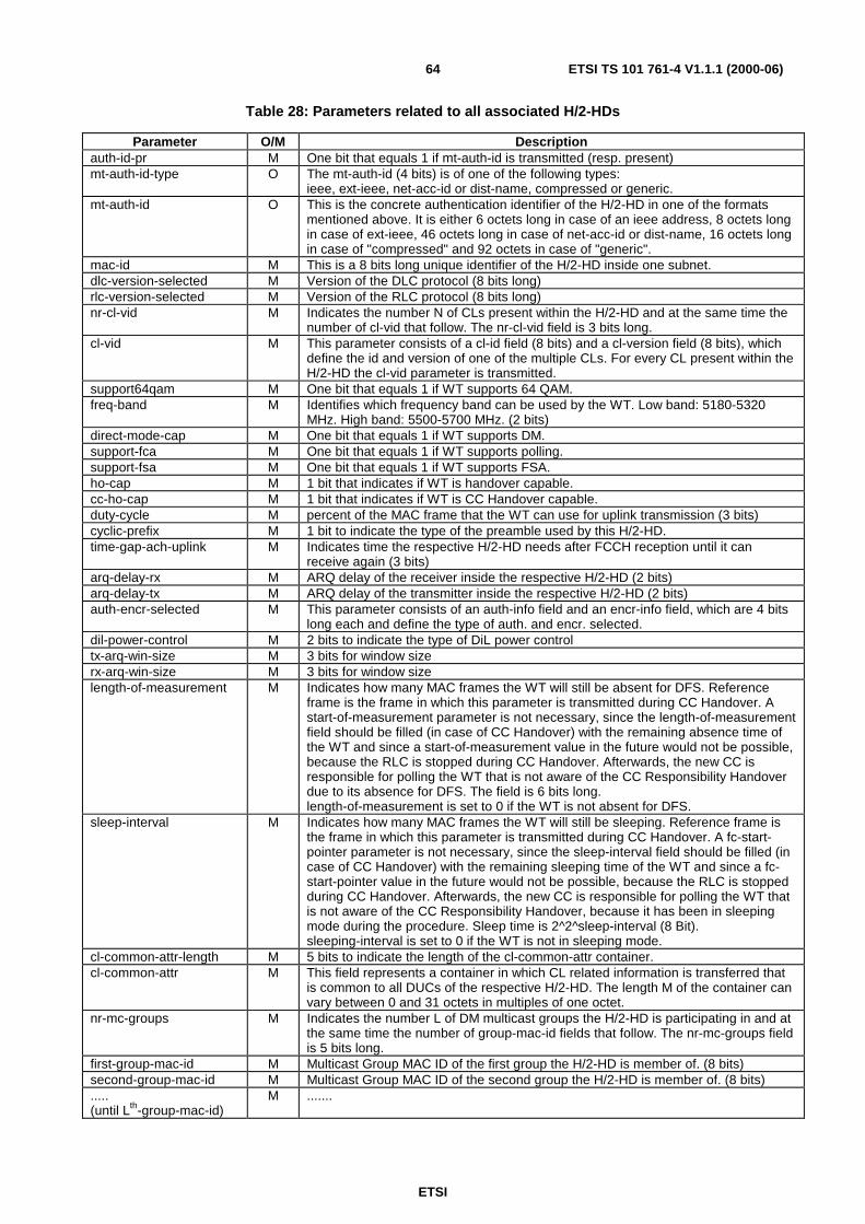
ETSI
ETSI TS 101 761-4 V1.1.1 (2000-06)64
Table 28: Parameters related to all associated H/2-HDs
Parameter O/M Descriptionauth-id-pr M One bit that equals 1 if mt-auth-id is transmitted (resp. present)mt-auth-id-type O The mt-auth-id (4 bits) is of one of the following types:
ieee, ext-ieee, net-acc-id or dist-name, compressed or generic.mt-auth-id O This is the concrete authentication identifier of the H/2-HD in one of the formats
mentioned above. It is either 6 octets long in case of an ieee address, 8 octets longin case of ext-ieee, 46 octets long in case of net-acc-id or dist-name, 16 octets longin case of "compressed" and 92 octets in case of "generic".
mac-id M This is a 8 bits long unique identifier of the H/2-HD inside one subnet.dlc-version-selected M Version of the DLC protocol (8 bits long)rlc-version-selected M Version of the RLC protocol (8 bits long)nr-cl-vid M Indicates the number N of CLs present within the H/2-HD and at the same time the
number of cl-vid that follow. The nr-cl-vid field is 3 bits long.cl-vid M This parameter consists of a cl-id field (8 bits) and a cl-version field (8 bits), which
define the id and version of one of the multiple CLs. For every CL present within theH/2-HD the cl-vid parameter is transmitted.
support64qam M One bit that equals 1 if WT supports 64 QAM.freq-band M Identifies which frequency band can be used by the WT. Low band: 5180-5320
MHz. High band: 5500-5700 MHz. (2 bits)direct-mode-cap M One bit that equals 1 if WT supports DM.support-fca M One bit that equals 1 if WT supports polling.support-fsa M One bit that equals 1 if WT supports FSA.ho-cap M 1 bit that indicates if WT is handover capable.cc-ho-cap M 1 bit that indicates if WT is CC Handover capable.duty-cycle M percent of the MAC frame that the WT can use for uplink transmission (3 bits)cyclic-prefix M 1 bit to indicate the type of the preamble used by this H/2-HD.time-gap-ach-uplink M Indicates time the respective H/2-HD needs after FCCH reception until it can
receive again (3 bits)arq-delay-rx M ARQ delay of the receiver inside the respective H/2-HD (2 bits)arq-delay-tx M ARQ delay of the transmitter inside the respective H/2-HD (2 bits)auth-encr-selected M This parameter consists of an auth-info field and an encr-info field, which are 4 bits
long each and define the type of auth. and encr. selected.dil-power-control M 2 bits to indicate the type of DiL power controltx-arq-win-size M 3 bits for window sizerx-arq-win-size M 3 bits for window sizelength-of-measurement M Indicates how many MAC frames the WT will still be absent for DFS. Reference
frame is the frame in which this parameter is transmitted during CC Handover. Astart-of-measurement parameter is not necessary, since the length-of-measurementfield should be filled (in case of CC Handover) with the remaining absence time ofthe WT and since a start-of-measurement value in the future would not be possible,because the RLC is stopped during CC Handover. Afterwards, the new CC isresponsible for polling the WT that is not aware of the CC Responsibility Handoverdue to its absence for DFS. The field is 6 bits long.length-of-measurement is set to 0 if the WT is not absent for DFS.
sleep-interval M Indicates how many MAC frames the WT will still be sleeping. Reference frame isthe frame in which this parameter is transmitted during CC Handover. A fc-start-pointer parameter is not necessary, since the sleep-interval field should be filled (incase of CC Handover) with the remaining sleeping time of the WT and since a fc-start-pointer value in the future would not be possible, because the RLC is stoppedduring CC Handover. Afterwards, the new CC is responsible for polling the WT thatis not aware of the CC Responsibility Handover, because it has been in sleepingmode during the procedure. Sleep time is 2^2^sleep-interval (8 Bit).sleeping-interval is set to 0 if the WT is not in sleeping mode.
cl-common-attr-length M 5 bits to indicate the length of the cl-common-attr container.cl-common-attr M This field represents a container in which CL related information is transferred that
is common to all DUCs of the respective H/2-HD. The length M of the container canvary between 0 and 31 octets in multiples of one octet.
nr-mc-groups M Indicates the number L of DM multicast groups the H/2-HD is participating in and atthe same time the number of group-mac-id fields that follow. The nr-mc-groups fieldis 5 bits long.
first-group-mac-id M Multicast Group MAC ID of the first group the H/2-HD is member of. (8 bits)second-group-mac-id M Multicast Group MAC ID of the second group the H/2-HD is member of. (8 bits).....(until Lth-group-mac-id)
M .......
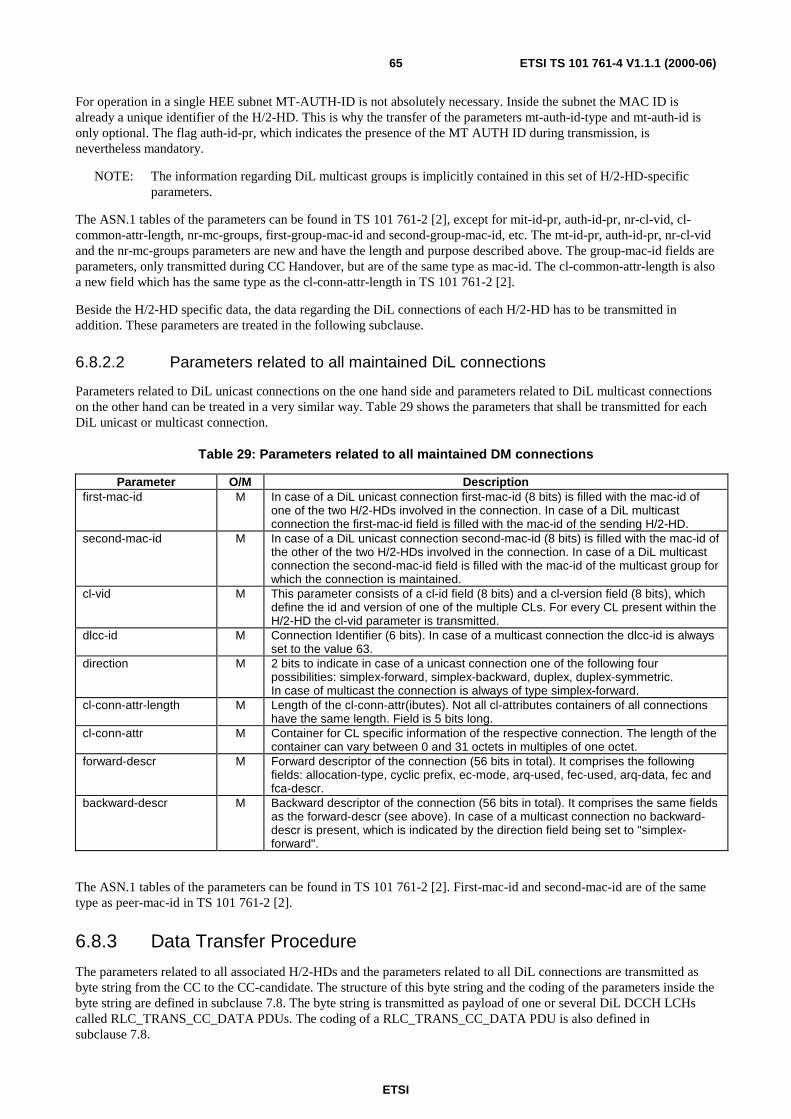
ETSI
ETSI TS 101 761-4 V1.1.1 (2000-06)65
For operation in a single HEE subnet MT-AUTH-ID is not absolutely necessary. Inside the subnet the MAC ID isalready a unique identifier of the H/2-HD. This is why the transfer of the parameters mt-auth-id-type and mt-auth-id isonly optional. The flag auth-id-pr, which indicates the presence of the MT AUTH ID during transmission, isnevertheless mandatory.
NOTE: The information regarding DiL multicast groups is implicitly contained in this set of H/2-HD-specificparameters.
The ASN.1 tables of the parameters can be found in TS 101 761-2 [2], except for mit-id-pr, auth-id-pr, nr-cl-vid, cl-common-attr-length, nr-mc-groups, first-group-mac-id and second-group-mac-id, etc. The mt-id-pr, auth-id-pr, nr-cl-vidand the nr-mc-groups parameters are new and have the length and purpose described above. The group-mac-id fields areparameters, only transmitted during CC Handover, but are of the same type as mac-id. The cl-common-attr-length is alsoa new field which has the same type as the cl-conn-attr-length in TS 101 761-2 [2].
Beside the H/2-HD specific data, the data regarding the DiL connections of each H/2-HD has to be transmitted inaddition. These parameters are treated in the following subclause.
6.8.2.2 Parameters related to all maintained DiL connections
Parameters related to DiL unicast connections on the one hand side and parameters related to DiL multicast connectionson the other hand can be treated in a very similar way. Table 29 shows the parameters that shall be transmitted for eachDiL unicast or multicast connection.
Table 29: Parameters related to all maintained DM connections
Parameter O/M Descriptionfirst-mac-id M In case of a DiL unicast connection first-mac-id (8 bits) is filled with the mac-id of
one of the two H/2-HDs involved in the connection. In case of a DiL multicastconnection the first-mac-id field is filled with the mac-id of the sending H/2-HD.
second-mac-id M In case of a DiL unicast connection second-mac-id (8 bits) is filled with the mac-id ofthe other of the two H/2-HDs involved in the connection. In case of a DiL multicastconnection the second-mac-id field is filled with the mac-id of the multicast group forwhich the connection is maintained.
cl-vid M This parameter consists of a cl-id field (8 bits) and a cl-version field (8 bits), whichdefine the id and version of one of the multiple CLs. For every CL present within theH/2-HD the cl-vid parameter is transmitted.
dlcc-id M Connection Identifier (6 bits). In case of a multicast connection the dlcc-id is alwaysset to the value 63.
direction M 2 bits to indicate in case of a unicast connection one of the following fourpossibilities: simplex-forward, simplex-backward, duplex, duplex-symmetric.In case of multicast the connection is always of type simplex-forward.
cl-conn-attr-length M Length of the cl-conn-attr(ibutes). Not all cl-attributes containers of all connectionshave the same length. Field is 5 bits long.
cl-conn-attr M Container for CL specific information of the respective connection. The length of thecontainer can vary between 0 and 31 octets in multiples of one octet.
forward-descr M Forward descriptor of the connection (56 bits in total). It comprises the followingfields: allocation-type, cyclic prefix, ec-mode, arq-used, fec-used, arq-data, fec andfca-descr.
backward-descr M Backward descriptor of the connection (56 bits in total). It comprises the same fieldsas the forward-descr (see above). In case of a multicast connection no backward-descr is present, which is indicated by the direction field being set to "simplex-forward".
The ASN.1 tables of the parameters can be found in TS 101 761-2 [2]. First-mac-id and second-mac-id are of the sametype as peer-mac-id in TS 101 761-2 [2].
6.8.3 Data Transfer Procedure
The parameters related to all associated H/2-HDs and the parameters related to all DiL connections are transmitted asbyte string from the CC to the CC-candidate. The structure of this byte string and the coding of the parameters inside thebyte string are defined in subclause 7.8. The byte string is transmitted as payload of one or several DiL DCCH LCHscalled RLC_TRANS_CC_DATA PDUs. The coding of a RLC_TRANS_CC_DATA PDU is also defined insubclause 7.8.

ETSI
ETSI TS 101 761-4 V1.1.1 (2000-06)66
If the byte string has to be transmitted on several RLC_TRANS_CC_DATA PDUs, it has to be segmented. Thecomplete byte string shall be reassembled in the receiver. To reassemble the payload of the RLC_TRANS_CC_DATAPDUs in the correct order, each PDU shall have a Sequence Number (SN). For this purpose the SN-field defined in [1]shall be used. This is possible because the field is in general not used in case of a DiL DCCH.
To ensure the integrity of the transmitted data, a "Go-back-n" ARQ mechanism shall be applied on theRLC_TRANS_CC_DATA PDUs using RLC_TRANS_CC_DATA_ACK PDUs. The sender window is implicitlydefined by the size of the SN-field (1 024 PDUs).
NOTE 1: It is implementation specific and e.g. load dependent, how many RLC_TRANS_CC_DATA_PDUs aretransmitted before the sender (CC) waits for a RLC_TRANS_CC_DATA_ACK sent by the receiver (CC-candidate).
With a RLC_TRANS_CC_DATA_ACK PDU the receiver acknowledges all PDUs up to an indicated SN-1. AReceiveReady-flag (RR-flag) inside the RLC_TRANS_CC_DATA_ACK indicates whether further PDUs (starting withSN) have not been correctly received (RR-flag=0) or whether all PDUs up to (and including) SN have been correctlyreceived (RR-flag=1). In the first case the sender (CC) shall re-send all PDUs beginning with the indicated SN.
NOTE 2: In the second case the acknowledged SN may be lower than the SN of the last sent PDU. This may occurif the receiver (CC-candidate) has not yet processed the remaining PDUs. Nevertheless, the sender (CC)shall continue transmission of RLC_TRANS_CC_DATA PDUs beginning with SN where he hadpreviously stopped transmission.
If the sender (CC) has not received a RLC_TRANS_CC_DATA_ACK PDU within time T_trans_cc_data_cc, it shallre-send all RLC_TRANS_CC_DATA PDUs from the last acknowledged SN on. The receiver (CC-candidate) shall sendat least one RLC_TRANS_CC_DATA_ACK PDU per frame (if there are RLC_TRANS_CC_DATA PDUs that havenot yet been acknowledged).
The timer T_trans_cc_data_cc shall be set to 6 ms.
6.9 Authentication Key ManagementDuring association, the authentication phase is performed by a challenge/response technique in which each end-entity(CC and WT) uses a common secret authentication key auth-key to respond to the challenge sent by the other entity.Therefore, auth-key shall be downloaded into each H2-HD. Support for Authentication Key Distribution is mandatoryfor all H/2-HDs.
Before a H/2-HD can take part in normal operation, meaning to start the CC selection process as a CC-capable device,or to start the association process as a basic WT, it shall first be initialized with the common secret authentication keyand the owner identifier NET-ID of the home network. auth-key and NET-ID shall only be generated by the first CC-capable device to be installed in the home network and shall then be distributed to each new device to be installed. TheNET-ID is broadcast by the CC in the BCCH and therefore known to every WT to be installed. The new WT shall storethe NET-ID locally.. The authentication key auth-key is distributed in a secure way to avoid:
• The key to be discovered by an eavesdropper;
• The registration of an attacker's devices on a network.
To avoid the registration of attacker's devices on a home network, each network shall be protected by a up to 23 octetsPIN (Personal Identification Number). This PIN shall be stored in the CC (or each CC-capable device). When installinga new device, the user shall be asked via an implementation specific user interface whether:
1) The device is the first device to be installed in the network;
2) The device is a new additional device in the network (in that case, another device shall already have beeninstalled in the network).
In the first case, the CC capable device to be installed shall act as a CC without performing CC Selection, and shallgenerate the secret auth-key and the owner identifier NET-ID. In the second case, the new device to be installed shall actas a WT without performing CC Selection; the existing CC broadcasts NET-ID and shall send auth-key to this newdevice.

ETSI
ETSI TS 101 761-4 V1.1.1 (2000-06)67
The PIN is CC-defined and a way of recovery may exist in case the PIN is lost. This way may be different for eachmanufacturer and is out of the scope of the present document. Moreover, a user may have the ability to change his PIN.
6.9.1 Installation of the First Device in the Network
Using an implementation specific interface, the user shall be asked if the device to be installed shall be the firstoperational device of a network. The first device of a network shall be CC-capable. To avoid wrong setting by the user,the device may indicate to the user if it has detected other CCs with or without displaying the associated NET-IDs. If theuser set the device as the first device in the network, the device shall act as the CC on a free frequency and shall generatethe secret key auth-key and the owner identifier NET-ID. Before generating them, the CC inquire the network's PINfrom the user. If the PIN is validated by the CC, the CC generates auth-key and NET-ID.
auth-key shall be the output of a random generator, or the result of a function f that depends on several parameters suchas the device identifier, the network PIN and so on:
auth-key = f(device_id, PIN,…).
The function f shall ensure the approximate uniqueness of auth-key. This means that given two different possible inputsof f, the probability of obtaining the same key auth-key shall be less than 2-40. However, f may be different for eachmanufacturer and its definition is out of the scope of the present document.
NET-ID shall be a random number between 0 and 959. During the installation and normal operation, the NET-ID shallbe sent on BCCH by the acting CC.
The user shall be able to undo or renew this first device installation process whenever he/she wants.
NOTE: The manufacturer should make clear in the user manual that the user should not configure a new CC-capable device as the first one, if there is already one installed.
If multiple CC-capable devices are configured by the user as the first devices of a network. It is very likelythat they generate independent networks with different owner identifiers and authentication keys.
By looking at an implementation specific indicator on each CC-capable device, the user should be able todetect if more than one CC is active at a time. If the user wants to have one single networks, he/she shouldundo the installation process of all CCs, except the one that he/she wants to keep.
6.9.2 Installation of a New Device in the Network
The generated authentication key auth-key shall be downloaded into each new device before it can use the network. Thisdownload phase involves the participation of the CC and the new H2-HD, and is composed of the following steps:
1) Via an implementation specific user interface, the user shall activate the installation phase on the CC to installa new device;
2) The CC shall inquire the network PIN from the user. If the entered PIN is validated by the CC, the downloadprocess is started and remains valid during a time window; The user may determine the duration of the timewindow;
3) The user shall activate the installation phase on the new H2-HD to be installed. This device shall associatewith the CC, requesting unicast encryption but no authentication. At the end of this association phase, the H2-HD and the CC agree on an encryption algorithm A (A may be DES or 3DES) and execute a Diffie-Hellmankey exchange. The result of this step is a secret session key SSK shared by the new device and the CC. Thissession key shall be used by the algorithm A negotiated in the previous step. Figure 30 gives an overviewwhich parts of the association procedure are carried out for the installation purpose.
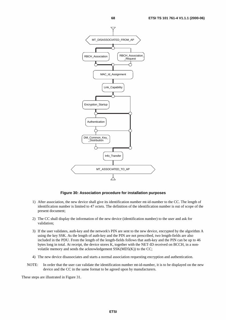
ETSI
ETSI TS 101 761-4 V1.1.1 (2000-06)68
MT_DISASSOCIATED_FROM_AP
MAC_Id_Assignment
Link_Capability
MT_ASSOCIATED_TO_AP
Authentication
Encryption_Startup
Info_Transfer
DM_Common_Key__Distribution
RBCH_Association RBCH_Association__Request
Figure 30: Association procedure for installation purposes
1) After association, the new device shall give its identification number mt-id-number to the CC. The length ofidentification number is limited to 47 octets. The definition of the identification number is out of scope of thepresent document;
2) The CC shall display the information of the new device (identification number) to the user and ask forvalidation;
3) If the user validates, auth-key and the network's PIN are sent to the new device, encrypted by the algorithm Ausing the key SSK. As the length of auth-key and the PIN are not prescribed, two length-fields are alsoincluded in the PDU. From the length of the length-fields follows that auth-key and the PIN can be up to 46bytes long in total. At receipt, the device stores K, together with the NET-ID received on BCCH, in a non-volatile memory and sends the acknowledgement SSK(MD5(K)) to the CC;
4) The new device disassociates and starts a normal association requesting encryption and authentication.
NOTE: In order that the user can validate the identification number mt-id-number, it is to be displayed on the newdevice and the CC in the same format to be agreed upon by manufacturers.
These steps are illustrated in Figure 31.

ETSI
ETSI TS 101 761-4 V1.1.1 (2000-06)69
MT_RLC CC_RLC CC_ENVMT_ENV
Authentication_Key_Exchanged
User shall confirm ifMT_ID_NUMBER
is valid or not
New_Device_Installation_Initiated
MSC Authentication_Key_Management_for_HE
RLC_AUTHENTICATION_KEY_REQUEST
(mt-id-number-length,mt-id-number )
ACF_auth_key_tranfer_cnf
(mac-id,valid-key,md5-of-auth-key)
RLC_AUTHENTICATION_KEY_TRANSFER_ACK
(valid-key,md5-of-auth-key)
ACF_auth_key_tranfer_rsp
(mac-id,valid-key,md5-of-auth-key)
ACF_auth_key_tranfer_ind
( mac-id,valid-key,
auth-key-length,pin-code-length,
auth-key, pin-code)
ACF_auth_key_tranfer_req
( mac-id,valid-key,
auth-key-length,pin-code-length,
auth-key, pin-code)
RLC_AUTHENTICATION_KEY_TRANSFER
( valid-key,auth-key-length,pin-code-length,
auth-key,pin-code)
ACF_auth_key_request_cnf
(mac-id)
ACF_auth_key_request_req
(mac-id,mt-id-number-length,mt-id-number )
ACF_auth_key_request_rsp
(mac-id)
ACF_auth_key_request_ind
(mac-id,mt-id-number-length,mt-id-number )
T_authentication_key_transfer_cc
RLC_AUTHENTICATION_KEY_REQUEST_ACK
T_authentication_key_request_mt
Figure 31: Messages exchanged during the installation of a new device
Table 30: RLC-AUTHENTICATION-KEY-REQUEST
RLC-AUTHENTICATION-KEY-REQUEST-ARG::= SEQUENCE{rlc-pdu-type RLC-HE-LCH-PDU-TYPE,extension-type EXTENSION-TYPE,mt-id-number-length MT-ID-NUMBER-LENGTH,mt-id-number MT-ID-NUMBER }

ETSI
ETSI TS 101 761-4 V1.1.1 (2000-06)70
Table 31: RLC-AUTHENTICATION-KEY-REQUEST-ACK
RLC-AUTHENTICATION-KEY-REQUEST-ACK-ARG::= SEQUENCE{rlc-pdu-type RLC-HE-SCH-PDU-TYPEextension-type EXTENSION-TYPE,}
Table 32: RLC-AUTHENTICATION-KEY-TRANSFER
RLC-AUTHENTICATION-KEY-TRANSFER-ARG::= SEQUENCE{rlc-pdu-type RLC-HE-LCH-PDU-TYPE,extension-type EXTENSION-TYPE,valid-key VALID-KEY,
-- indicated whether the exchanged-- key is valid or not
auth-key-length AUTH-KEY-LENGTH,pin-code-length PIN-CODE-LENGTH,auth-key AUTH-KEY,pin-code PIN-CODE}
Table 33: RLC-AUTHENTICATION-KEY-TRANSFER-ACK
RLC-AUTHENTICATION-KEY-TRANSFER-ACK-ARG::= SEQUENCE{rlc-pdu-type RLC-HE-SCH-PDU-TYPE,extension-type EXTENSION-TYPE,valid-key VALID-KEY,
-- indicated whether the exchanged-- key is valid or not
md5-of-auth-key MD5-ON-KEY}
To download the common authentication key and the owner identifier from the CC, the new device shall first run anassociation phase without the authentication procedure. It shall abort this association, as soon as it detects that the CC tobe associated with is a Non HE-compliant Device. If more than one active HE-compliant CCs are detected, the newdevice to be installed shall try out the CC, whose download process has been started by the user. When theauthentication key has been exchanged, the WT shall disassociate and run the association procedure with theauthentication phase.
NOTE: The installation phase activation mentioned in steps (1) and (3) depends on the manufacturers and is outthe scope of the present document. Moreover, the choice of algorithm A in step (3) depends on therequired security level. The standard does not impose any algorithm but recommend to use 3DES to reacha high level of security.
Three new RLC messages are introduced, namely RLC_AUTHENTICATION_KEY_REQUEST,RLC_AUTHENTICATION_KEY_TRANSFER, RLC_AUTHENTICATION_KEY_TRANSFER_ACK. The encodingof these RLC PDUs is defined in subclause 7.9.
Once a H2-HD is installed, it can be reinstalled in any new network by repeating the eight operations mentioned aboveon the new network. In that case, the old authentication key may be deleted and replaced by the new one, if themanufacturer only supports one usage profile. Using an implementation specific user interface, the user may be enabledto select different usage profiles. Different usage profiles may correspond to different independent networks in the sameor different places. In this case, for each usage profile a specific authentication key and owner identifier can bedownloaded and stored in the H/2-HD.

ETSI
ETSI TS 101 761-4 V1.1.1 (2000-06)71
7 RLC Protocol Data Units
7.1 GeneralThe general concept of the transfer syntax of RLC is described in TS 101 761-1 [1] and TS 101 761-2 [2]. The specifictransfer syntax formats for DiL RLC messages using SCH or LCH are defined below:
Table 34: Transfer syntax format of the RLC SCH in Direct Link
8 7 6 5 4 3 2 1Octet 1 Defined in DLC TS Future UseOctet 2 MSB RLC SCH PDU typeOctet 3 MSB EXTENSION-TYPE MSB RLC DATAOctet 4
…Octet 7
MSB RLC DATA
Table 35: Transfer syntax format of the RLC LCH in Direct Link
8 7 6 5 4 3 2 1Octet 1 Defined in DLC TS MSB Sequence numberOctet 2 Sequence number MSB EXTENSION-TYPE Future use
Octet 3 MSB RLC LCH PDU typeOctet 4
…
Octet 51
MSB RLC DATA
The definition of MSB for coding of RLC messages and its usage rules are given in TS 101 761-2 [2] (subclause 4.4).
Table 36 lists all RLC messages defined in TS 101 761-2 [2] with changed requirement for support, i.e. theimplementation changes from optional to mandatory.
Table 36: RLC messages with changed requirement for support
RLC MESSAGE CC-capableWTO/M
basicWTO/M
RLC_DM_COMMON_KEY_DISTR_(/ACK) M MRLC_INFO_(-/ACK) M MRLC_GROUP_JOIN_(/ACK/NACK) M ORLC_GROUP_LEAVE_(/ACK/NACK) M ORLC_DM_SETUP M MRLC_DM_CONNECT_(-/ACK/COMPLETE) M MRLC_DM_RELEASE_(-/ACK) M MRLC_DM_RESET_(-/ACK) M M
Table 37 lists all parameters added or changed indicating whether the support is mandatory or optional.
Table 37: Parameters added/changed
Parameter O/M Descriptiondm-attributes M Additional parameters needed for the DM are transferred as DM-Attributes.
This parameter is for future use.
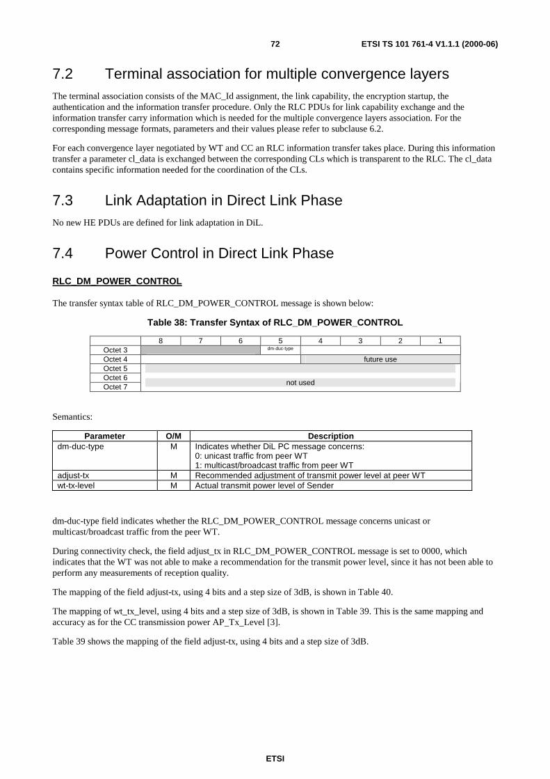
ETSI
ETSI TS 101 761-4 V1.1.1 (2000-06)72
7.2 Terminal association for multiple convergence layersThe terminal association consists of the MAC_Id assignment, the link capability, the encryption startup, theauthentication and the information transfer procedure. Only the RLC PDUs for link capability exchange and theinformation transfer carry information which is needed for the multiple convergence layers association. For thecorresponding message formats, parameters and their values please refer to subclause 6.2.
For each convergence layer negotiated by WT and CC an RLC information transfer takes place. During this informationtransfer a parameter cl_data is exchanged between the corresponding CLs which is transparent to the RLC. The cl_datacontains specific information needed for the coordination of the CLs.
7.3 Link Adaptation in Direct Link PhaseNo new HE PDUs are defined for link adaptation in DiL.
7.4 Power Control in Direct Link Phase
RLC_DM_POWER_CONTROL
The transfer syntax table of RLC_DM_POWER_CONTROL message is shown below:
Table 38: Transfer Syntax of RLC_DM_POWER_CONTROL
8 7 6 5 4 3 2 1Octet 3 dm-duc-type
Octet 4 future useOctet 5Octet 6Octet 7
not used
Semantics:
Parameter O/M Descriptiondm-duc-type M Indicates whether DiL PC message concerns:
0: unicast traffic from peer WT1: multicast/broadcast traffic from peer WT
adjust-tx M Recommended adjustment of transmit power level at peer WTwt-tx-level M Actual transmit power level of Sender
dm-duc-type field indicates whether the RLC_DM_POWER_CONTROL message concerns unicast ormulticast/broadcast traffic from the peer WT.
During connectivity check, the field adjust_tx in RLC_DM_POWER_CONTROL message is set to 0000, whichindicates that the WT was not able to make a recommendation for the transmit power level, since it has not been able toperform any measurements of reception quality.
The mapping of the field adjust-tx, using 4 bits and a step size of 3dB, is shown in Table 40.
The mapping of wt_tx_level, using 4 bits and a step size of 3dB, is shown in Table 39. This is the same mapping andaccuracy as for the CC transmission power AP_Tx_Level [3].
Table 39 shows the mapping of the field adjust-tx, using 4 bits and a step size of 3dB.

ETSI
ETSI TS 101 761-4 V1.1.1 (2000-06)73
Table 39: Mapping of adjust-tx field
adjust-tx Adjust power level by:
0000No change /
Not enough measurements
0001 − 3 dB
0010 − 6 dB
… …
0111 − 21 dB
1000 Not used
1001 + 3 dB
1010 + 6 dB
… …
1111 + 21 dB
Table 40 shows the mapping of wt-tx-level, using 4 bits and a step size of 3dB.
Table 40: Mapping of wt-tx-level field
wt-tx-level Mean EIRP [dBm] Accuracy [dB]
1111 30 +/- 4
1110 27 +/- 4
1101 24 +/- 4
1100 21 +/- 4
1011 18 +/- 4
1010 15 +/- 5
1001 12 +/- 5
1000 9 +/- 5
0111 6 +/- 6
0110 3 +/- 6
0101 0 +/- 6
0100 -3 +/- 6
0011 -6 +/- 6
0010 -9 +/- 6
0001 -12 +/- 8
0000 -15 +/- 8

ETSI
ETSI TS 101 761-4 V1.1.1 (2000-06)74
7.5 Link Quality Calibration for DM operationRLC_CALIBRATION_MEASUREMENT_TRIGGER
The transfer syntax table of RLC_CALIBRATION_MEASUREMENT_TRIGGER message is shown below:
Table 41: Transfer Syntax of RLC_CALIBRATION_MEASUREMENT_TRIGGER
8 7 6 5 4 3 2 1Octet 3 trigger-type future useOctet 4 mac-id-1 (presence depending on trigger-type)Octet 5 mac-id-2 (presence depending on trigger-type)Octet 6 mac-id-3 (presence depending on trigger-type)Octet 7 not used
Semantics:
Parameter O/M Descriptiontrigger-type M 2 bits that indicate if one, two, three or all WTs are triggered:
00� All WTs are triggered (no MAC-ID included)01� One WT is triggered10� Two WTs are triggered11� Three WTs are triggered
mac-ids M MAC-ID of triggered WTs (up to 3), in case of selective calibrations.
RLC_CALIBRATION _ MEASUREMENT
The transfer syntax table of RLC_CALIBRATION_MEASUREMENT message is shown below (no parameters arecontained):
Table 42: Transfer Syntax of RLC_CALIBRATION_MEASUREMENT
8 7 6 5 4 3 2 1Octet 3Octet 4Octet 5Octet 6Octet 7
Not used
Semantics:
Parameter O/M DescriptionNo parameters included
RLC_CALIBRATION _REPORT_TRIGGER
The transfer syntax table of RLC_CALIBRATION_REPORT_TRIGGER message is shown below:
Table 43: Transfer Syntax of RLC_CALIBRATION_REPORT_TRIGGER
8 7 6 5 4 3 2 1Octet 3 trigger-type future useOctet 4 mac-id-1 (presence depending on trigger-type)Octet 5 mac-id-2 (presence depending on trigger-type)Octet 6 mac-id-3 (presence depending on trigger-type)Octet 7 not used
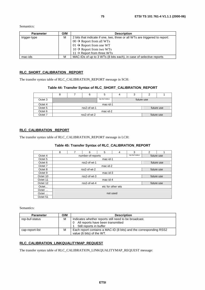
ETSI
ETSI TS 101 761-4 V1.1.1 (2000-06)75
Semantics:
Parameter O/M Descriptiontrigger-type M 2 bits that indicate if one, two, three or all WTs are triggered to report:
00� Report from all WTs01� Report from one WT10� Report from two WTs11� Report from three WTs
mac-ids M MAC-IDs of up to 3 WTs (8 bits each), in case of selective reports
RLC_SHORT_CALIBRATION _REPORT
The transfer syntax table of RLC_CALIBRATION_REPORT message in SCH:
Table 44: Transfer Syntax of RLC_SHORT_CALIBRATION_REPORT
8 7 6 5 4 3 2 1
Octet 3 rep-buf-status future use
Octet 4 mac-id-1Octet 5 rss2-of-wt-1 future useOctet 6 mac-id-2Octet 7 rss2-of-wt-2 future use
RLC_CALIBRATION _REPORT
The transfer syntax table of RLC_CALIBRATION_REPORT message in LCH:
Table 45: Transfer Syntax of RLC_CALIBRATION_REPORT
8 7 6 5 4 3 2 1Octet 4 number-of-reports rep-buf-status future useOctet 5 mac-id-1Octet 6 rss2-of-wt-1 future useOctet 7 mac-id-2Octet 8 rss2-of-wt-2 future useOctet 9 mac-id-3Octet 10 rss2-of-wt-3 future useOctet 11 mac-id-4Octet 12 rss2-of-wt-4 future useOctet... etc for other wtsOctet …Octet …Octet 51
not used
Semantics:
Parameter O/M Descriptionrep-buf-status M Indicates whether reports still need to be broadcast.
0 All reports have been transmitted1 Still reports in buffer
cap-report-list M Each report contains a MAC-ID (8 bits) and the corresponding RSS2value (6 bits) of the WT.
RLC_CALIBRATION_LINKQUALITYMAP_REQUEST
The transfer syntax table of RLC_CALIBRATION_LINKQUALITYMAP_REQUEST message:
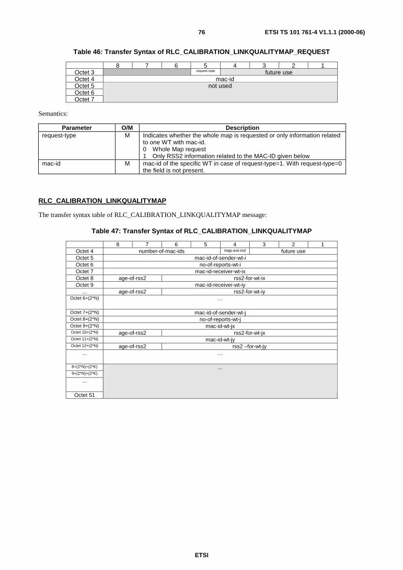
ETSI
ETSI TS 101 761-4 V1.1.1 (2000-06)76
Table 46: Transfer Syntax of RLC_CALIBRATION_LINKQUALITYMAP_REQUEST
8 7 6 5 4 3 2 1Octet 3 request-type future useOctet 4 mac-idOctet 5Octet 6Octet 7
not used
Semantics:
Parameter O/M Descriptionrequest-type M Indicates whether the whole map is requested or only information related
to one WT with mac-id.0 Whole Map request1 Only RSS2 information related to the MAC-ID given below
mac-id M mac-id of the specific WT in case of request-type=1. With request-type=0the field is not present.
RLC_CALIBRATION_LINKQUALITYMAP
The transfer syntax table of RLC_CALIBRATION_LINKQUALITYMAP message:
Table 47: Transfer Syntax of RLC_CALIBRATION_LINKQUALITYMAP
8 7 6 5 4 3 2 1Octet 4 number-of-mac-ids map-ext-ind future useOctet 5 mac-id-of-sender-wt-iOctet 6 no-of-reports-wt-iOctet 7 mac-id-receiver-wt-ixOctet 8 age-of-rss2 rss2-for-wt-ixOctet 9 mac-id-receiver-wt-iy
... age-of-rss2 rss2-for-wt-iyOctet 6+(2*N) …
Octet 7+(2*N) mac-id-of-sender-wt-jOctet 8+(2*N) no-of-reports-wt-jOctet 9+(2*N) mac-id-wt-jxOctet 10+(2*N) age-of-rss2 rss2-for-wt-jxOctet 11+(2*N) mac-id-wt-jyOctet 12+(2*N) age-of-rss2 rss2 –for-wt-jy
... …
8+(2*N)+(2*K)
9+(2*N)+(2*K)
...
Octet 51
...
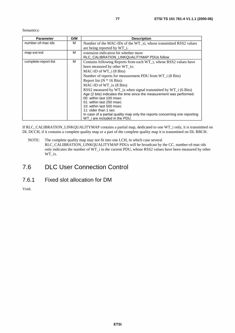
ETSI
ETSI TS 101 761-4 V1.1.1 (2000-06)77
Semantics:
Parameter O/M Descriptionnumber-of-mac-ids M Number of the MAC-IDs of the WT_xi, whose transmitted RSS2 values
are being reported by WT_i.map-ext-ind M extension indication bit whether more
RLC_CALIBRATION_LINKQUALITYMAP PDUs followcomplete-report-list M Contains following Reports from each WT_i, whose RSS2 values have
been measured by other WT_ix:MAC-ID of WT_i (8 Bits)Number of reports for measurement PDU from WT_i (8 Bits)Report list (N * 16 Bits):MAC-ID of WT_ix (8 Bits)RSS2 measured by WT_ix when signal transmitted by WT_i (6 Bits)Age (2 bits) indicates the time since the measurement was performed:00: within last 100 msec01: within last 250 msec10: within last 500 msec11: older than 1 secIn case of a partial quality map only the reports concerning one reportingWT_i are included in the PDU.
If RLC_CALIBRATION_LINKQUALITYMAP contains a partial map, dedicated to one WT_i only, it is transmitted onDL DCCH, if it contains a complete quality map or a part of the complete quality map it is transmitted on DL RBCH.
NOTE: The complete quality map may not fit into one LCH, in which case severalRLC_CALIBRATION_LINKQUALITYMAP PDUs will be broadcast by the CC. number-of-mac-idsonly indicates the number of WT_i in the current PDU, whose RSS2 values have been measured by otherWT_ix.
7.6 DLC User Connection Control
7.6.1 Fixed slot allocation for DM
Void.

ETSI
ETSI TS 101 761-4 V1.1.1 (2000-06)78
7.6.2 Multicast in DiL phase
The transfer syntax tables below display the structures of all messages used for Direct Link Multicast Connection Setup,Modify and Release.
7.6.2.1 RLC-DM-MC-SETUP encoding
8 7 6 5 4 3 2 1Octet 4 PEER-MAC-IDOctet 5 SOURCE-MAC-IDOctet 6 CL-IDOctet 7 EXT-IND CL-ATTRIBUTE-LENGTH(L) # of DUC:sOctet 8 # of DUC:s(N) Future useOctet 9 DUC1- DLCC-IDOctet 10 MIN-REQ-RECEIVERS
CL-CONN ATTR
Octet Y DUC1-FW-TYPE-OF-ALLOCATION
Futureuse
cyclic-prefix
FEC-USED
EC-MODE
Octet... DUC1-FW-NUM-OF-RETRANSMISSIONS Future DUC1-FW-ARQ-WIN-SIZEFEC-FW Future Use
Octet... PER-#-MAC-FRAME(SCH) PER-#-MAC-FRAME(LCH)Octet... REQ PHY-MODE-SCH PHY-MODE-LCHOctet... REQUESTED-NUM-OF-LCHOctet... MINIMUM-NUM-OF-LCHOctet X DUC1-BW-TYPE-OF-
ALLOCATIONFuture
usecyclic-prefix
FEC-USED
EC-MODE
Octet... DUC1-BW-NUM-OF-RETRANSMISSIONS Future DUC1-BW-ARQ-WIN-SIZEFEC-BW Future Use
Octet... PER-#-MAC-FRAME(SCH) PER-#-MAC-FRAME(LCH)Octet... REQ PHY-MODE-SCH PHY-MODE-LCHOctet... REQUESTED-NUM-OF-LCHOctet... MINIMUM-NUM-OF-LCHOctet … CL-COMMON-ATTR-LENGTHOctet …Octet …Octet …
CL-COMMON-ATTR
Octet …Octet …Octet 51
Not used
Y=10+L
X=10+L+6 if asymmetric duplex with FCA and ARQ or FEC
Semantics of parameters specifically introduced for the DiL multicast case:

ETSI
ETSI TS 101 761-4 V1.1.1 (2000-06)79
Parameter O/M Descriptionsource-mac-id M identifies the multicast sendermin-req-receivers M number of receivers required to establish the multicast connectioncl-common-attr M common attributes concerning CLcl-common-attr-length M giving the length of the cl-common-attr field, can be set to zero.
7.6.2.2 RLC-DM-MC-CONNECT encoding
8 7 6 5 4 3 2 1Octet 4 PEER-MAC-IDOctet 5 SOURCE-MAC-IDOctet 6 CL-IDOctet 7 Future use CL-ATTRIBUTE-LENGTH(L) # of DUC:sOctet 8 # of DUC:s(N) Future useOctet 9 DUC1- DIRECTION DLCC-ID
CL-CONN ATTR
Octet Y DUC1-FW-TYPE-OF-ALLOCATION Future use cyclic- FEC-USED EC-MODE
Octet... DUC1-FW-NUM-OF-RETRANSMISSIONS Future use DUC1-FW-ARQ-WIN-SIZE
FEC-FW Future UseOctet... PER-#-MAC-FRAME(SCH) PER-#-MAC-FRAME(LCH)Octet... REQ SCH PHY-MODE-SCH PHY-MODE-LCHOctet... REQUESTED-NUM-OF-LCHOctet... MINUMUM-NUM-OF-LCHOctet X DUC1-BW-TYPE-OF-ALLOCATION Future use cyclic-
prefixFEC-USED EC-MODE
Octet... DUC1-BW-NUM-OF-RETRANSMISSIONS Future use DUC1-BW-ARQ-WIN-SIZE
FEC-BW Future UseOctet... PER-#-MAC-FRAME(SCH) PER-#-MAC-FRAME(LCH)Octet... REQ SCH PHY-MODE-SCH PHY-MODE-LCHOctet... REQUESTED-NUM-OF-LCHOctet... MINUMUM-NUM-OF-LCHOctet...Octet...
Octet 51Not used
Semantics of parameters specifically introduced for the DiL multicast case:
Parameter O/M Descriptionsource-mac-id M identifies the multicast sender

ETSI
ETSI TS 101 761-4 V1.1.1 (2000-06)80
7.6.2.3 RLC-DM-MC-CONNECT-ACK encoding
8 7 6 5 4 3 2 1Octet 4 PEER-MAC-IDOctet 5 SOURCE-MAC-IDOctet 6 CL-IDOctet 7 Future use CL-CONN-ATTR-LENGTH (L) # of DLCC:s+CL-ATTR
Octet 8 # of DLCCs (N) Future useOctet 9 Future use DLCC-ID-1Octet … CL-CONN-ATTR-1
Octet … Future use DLCC-ID-NOctet …
Octet8+L*N
CL-CONN-ATTR -N
Octet …Octet …Octet 51
Not used
Semantics of parameters specifically introduced for the DiL multicast case:
Parameter O/M Descriptionsource-mac-id M identifies the multicast sender
7.6.2.4 RLC-DM-MC-CONNECT-COMPLETE encoding
8 7 6 5 4 3 2 1Octet 4 PEER-MAC-IDOctet 5 SOURCE-MAC-IDOctet 6 Future use # of DLCC:s (N)Octet 7 Future use DLCC-ID -1Octet … Future use ...
Octet 5+N Future use DLCC-ID -NOctet 6+NOctet …Octet 51
Not used
Semantics of parameters specifically used for the DiL multicast case:
Parameter O/M Descriptionsource-mac-id M identifies the multicast sender
7.6.2.5 RLC-DM-MC-CONNECT-COMPLETE-ACK encoding
8 7 6 5 4 3 2 1Octet 3 Future useOctet 4 PEER-MAC-IDOctet 5 SOURCE-MAC-IDOctet 6Octet 7
Future use
Semantics of parameters specifically introduced for the DiL multicast case:
Parameter O/M Descriptionsource-mac-id M identifies the multicast sender
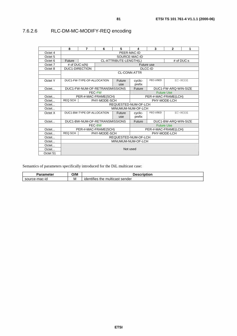
ETSI
ETSI TS 101 761-4 V1.1.1 (2000-06)81
7.6.2.6 RLC-DM-MC-MODIFY-REQ encoding
8 7 6 5 4 3 2 1Octet 4 PEER-MAC-IDOctet 5 SOURCE-MAC-IDOctet 6 Future CL-ATTRIBUTE-LENGTH(L) # of DUC:sOctet 7 # of DUC:s(N) Future useOctet 8 DUC1-DIRECTION DLCC-ID
CL-CONN ATTR
Octet Y DUC1-FW-TYPE-OF-ALLOCATION Futureuse
cyclic-prefix
FEC-USED EC-MODE
Octet... DUC1-FW-NUM-OF-RETRANSMISSIONS Future DUC1-FW-ARQ-WIN-SIZEFEC-FW Future Use
Octet... PER-#-MAC-FRAME(SCH) PER-#-MAC-FRAME(LCH)Octet... REQ SCH PHY-MODE-SCH PHY-MODE-LCHOctet... REQUESTED-NUM-OF-LCHOctet... MINUMUM-NUM-OF-LCHOctet X DUC1-BW-TYPE-OF-ALLOCATION Future
usecyclic-prefix
FEC-USED EC-MODE
Octet... DUC1-BW-NUM-OF-RETRANSMISSIONS Future DUC1-BW-ARQ-WIN-SIZEFEC-BW Future Use
Octet... PER-#-MAC-FRAME(SCH) PER-#-MAC-FRAME(LCH)Octet... REQ SCH PHY-MODE-SCH PHY-MODE-LCHOctet... REQUESTED-NUM-OF-LCHOctet... MINUMUM-NUM-OF-LCHOctet...Octet...Octet 51
Not used
Semantics of parameters specifically introduced for the DiL multicast case:
Parameter O/M Descriptionsource-mac-id M identifies the multicast sender
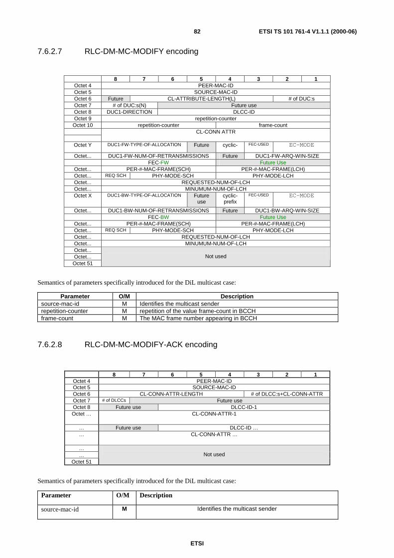
ETSI
ETSI TS 101 761-4 V1.1.1 (2000-06)82
7.6.2.7 RLC-DM-MC-MODIFY encoding
8 7 6 5 4 3 2 1Octet 4 PEER-MAC-IDOctet 5 SOURCE-MAC-IDOctet 6 Future CL-ATTRIBUTE-LENGTH(L) # of DUC:sOctet 7 # of DUC:s(N) Future useOctet 8 DUC1-DIRECTION DLCC-IDOctet 9 repetition-counter
Octet 10 repetition-counter frame-countCL-CONN ATTR
Octet Y DUC1-FW-TYPE-OF-ALLOCATION Future cyclic- FEC-USED EC-MODE
Octet... DUC1-FW-NUM-OF-RETRANSMISSIONS Future DUC1-FW-ARQ-WIN-SIZEFEC-FW Future Use
Octet... PER-#-MAC-FRAME(SCH) PER-#-MAC-FRAME(LCH)Octet... REQ SCH PHY-MODE-SCH PHY-MODE-LCHOctet... REQUESTED-NUM-OF-LCHOctet... MINUMUM-NUM-OF-LCHOctet X DUC1-BW-TYPE-OF-ALLOCATION Future
usecyclic-prefix
FEC-USED EC-MODE
Octet... DUC1-BW-NUM-OF-RETRANSMISSIONS Future DUC1-BW-ARQ-WIN-SIZEFEC-BW Future Use
Octet... PER-#-MAC-FRAME(SCH) PER-#-MAC-FRAME(LCH)Octet... REQ SCH PHY-MODE-SCH PHY-MODE-LCHOctet... REQUESTED-NUM-OF-LCHOctet... MINUMUM-NUM-OF-LCHOctet...Octet...Octet 51
Not used
Semantics of parameters specifically introduced for the DiL multicast case:
Parameter O/M Descriptionsource-mac-id M Identifies the multicast senderrepetition-counter M repetition of the value frame-count in BCCHframe-count M The MAC frame number appearing in BCCH
7.6.2.8 RLC-DM-MC-MODIFY-ACK encoding
8 7 6 5 4 3 2 1Octet 4 PEER-MAC-IDOctet 5 SOURCE-MAC-IDOctet 6 CL-CONN-ATTR-LENGTH # of DLCC:s+CL-CONN-ATTROctet 7 # of DLCCs Future useOctet 8 Future use DLCC-ID-1Octet … CL-CONN-ATTR-1
… Future use DLCC-ID …… CL-CONN-ATTR …
……
Octet 51Not used
Semantics of parameters specifically introduced for the DiL multicast case:
Parameter O/M Description
source-mac-id M Identifies the multicast sender

ETSI
ETSI TS 101 761-4 V1.1.1 (2000-06)83
7.6.2.9 RLC-DM-MC-RELEASE encoding
8 7 6 5 4 3 2 1Octet 4 PEER-MAC-IDOctet 5 SOURCE-MAC-IDOctet 6 CAUSE # of DLCC:sOctet 7 Future use DLCC-ID -1Octet 8 Future use …Octet … Future use DLCC-ID NOctet …Octet…Octet 51
Not used
Semantics of parameters specifically introduced for the DiL multicast case:
Parameter O/M Descriptionsource-mac-id M identifies the multicast sender
7.6.2.10 RLC-DM-MC-RELEASE-ACK encoding
8 7 6 5 4 3 2 1Octet 4 PEER-MAC-IDOctet 5 SOURCEMAC-IDOctet 6 Future use # of DLCC:sOctet 7 Future use DLCC-ID-1Octet 8 Future use …Octet … Future use DLCC-ID-NOctet …Octet…Octet 51
Not used
Semantics of parameters specifically introduced for the DiL multicast case:
Parameter O/M Descriptionsource-mac-id M identifies the multicast sender
7.7 Dynamic CC SelectionIn each CC Probing Frame a CC-capable device in the CC Selection Process transmits a Probing Beacon with thestructure of the usual BCCH and the following content:
ETSI
ETSI TS 101 761-4 V1.1.1 (2000-06)84
Table 48: Contents of the CC Probing BCCH
Name Length (bits) Setting
Frame counter (scrambler seed) 4 as defined in basic DLC TSNET-ID 10 0000000000AP-ID 10 0000000000Antenna ID 3 000AP TX level 4 1111AP RX UL level 3 000Pointer to FCH 12 000000000000Length FCH 4 0000PHY Mode of FCH 2 00Pointer to RCH 13 0000000000000Length of RCH 5 00000Guard space between RCH 2 00DL RBCH indicator 1 0DST (Data to sleeping terminals) 1 0Uplink preamble 1 0Version indicator 3 000AP traffic load indicator 3 000Maximum power indicator 1 1# of antenna elements 3 000Future use 14 anyCRC 24 as defined in 0Total length 120
The CC Probing BCCH is identified uniquely by 'Length of RCH' = 00000, which is not allowed in normal operation.All other fields shall be ignored on reception of a CC Probing BCCH.
7.8 CC Responsibility Handover
7.8.1 Encoding of CC Database Parameters for CC Handover
The H/2-HD specific parameters shall be encoded as in Table 49.

ETSI
ETSI TS 101 761-4 V1.1.1 (2000-06)85
Table 49: Transfer Syntax Table of H/2-HD Specific Parameters (Content-field of a H/2-HD-DATA-BLOCK)
8 7 6 5 4 3 2 1Octet 1 mac-idOctet 2 dlc-version-selectedOctet 3 rlc-version-selectedOctet 4 64-qam? freq-band dm-cap support-fca support-fsa nr-cl-vid (N)Octet 5 cl-id-1Octet 6 cl-version-1
... Other CL-ID and CL-Version
Octet 5+(2*N) ho-cap cc-ho-cap duty-cycle time-gap-ach-ulOctet 6+(2*N) arq-delay-rx arq-delay-tx auth-selectedOctet 7+(2*N) encr-selected cyclic prefix Future useOctet 8+(2*N) dil-power-control rx-arq-win-size tx-arq-win-sizeOctet 9+(2*N) length-of-measurement-DFS future use
Octet 10+(2*N) sleep-intervalOctet 11+(2*N) cl-common-attr-length (M octets) future use
...Octet
11+(2*N)+M
cl-common-attr
Oct.12+(2*N)+M nr-mc-groups (L) Future use... mac-id-1
Octet12+(2*N)+M+L
other-mac-ids
13+(2*N)+M+L auth-id-pr? mt-auth-id-type future use...
Octet19+(2*N)+M`+L
or21+(2*N)+M+L
or59+(2*N)+M+L
or105+(2*N)+M+L
mt-auth-id
8 7 6 5 4 3 2 1Octet 1 mac-idOctet 2 dlc-versionOctet 3 rlc-versionOctet 4 future use nr-cl-vid (N)Octet 5 cl-id-1Octet 6 cl-version-1
... Other CL-ID and CL-Version
Octet 5+(2*N) 64-qam? dm-cap dm-use-key polling? fsa? time-gap-ach-ulOctet 6+(2*N) arq-delay-rx arq-delay-tx auth-selectedOctet 7+(2*N) encr-selcted future useOctet 8+(2*N) dil-power-control rx-arq-win-size tx-arq-win-sizeOctet 9+(2*N) length-of-measurement-DFS future use
Octet 10+(2*N) sleep-intervalOctet 11+(2*N) cl-common-attr-length (M octets) future use
...Octet
11+(2*N)+M
cl-common-attr
Oct.12+(2*N)+M nr-mc-groups (L) Future use... mac-id-1
Octet12+(2*N)+M+L
other-mac-ids
13+(2*N)+M+L mt-id-pr? auth-id-pr? mt-auth-id-type future use...
Octet45+(2*N)+M
mt-id
...Octet
51+(2*N)+M
or 53+(2*N)+M
or 92+(2*N)+M
mt-auth-id
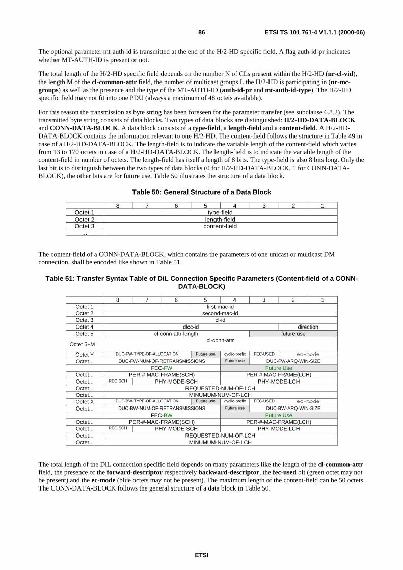
ETSI
ETSI TS 101 761-4 V1.1.1 (2000-06)86
The optional parameter mt-auth-id is transmitted at the end of the H/2-HD specific field. A flag auth-id-pr indicateswhether MT-AUTH-ID is present or not.
The total length of the H/2-HD specific field depends on the number N of CLs present within the H/2-HD (nr-cl-vid),the length M of the cl-common-attr field, the number of multicast groups L the H/2-HD is participating in (nr-mc-groups) as well as the presence and the type of the MT-AUTH-ID (auth-id-pr and mt-auth-id-type). The H/2-HDspecific field may not fit into one PDU (always a maximum of 48 octets available).
For this reason the transmission as byte string has been foreseen for the parameter transfer (see subclause 6.8.2). Thetransmitted byte string consists of data blocks. Two types of data blocks are distinguished: H/2-HD-DATA-BLOCKand CONN-DATA-BLOCK. A data block consists of a type-field, a length-field and a content-field. A H/2-HD-DATA-BLOCK contains the information relevant to one H/2-HD. The content-field follows the structure in Table 49 incase of a H/2-HD-DATA-BLOCK. The length-field is to indicate the variable length of the content-field which variesfrom 13 to 170 octets in case of a H/2-HD-DATA-BLOCK. The length-field is to indicate the variable length of thecontent-field in number of octets. The length-field has itself a length of 8 bits. The type-field is also 8 bits long. Only thelast bit is to distinguish between the two types of data blocks (0 for H/2-HD-DATA-BLOCK, 1 for CONN-DATA-BLOCK), the other bits are for future use. Table 50 illustrates the structure of a data block.
Table 50: General Structure of a Data Block
8 7 6 5 4 3 2 1Octet 1 type-fieldOctet 2 length-fieldOctet 3 content-field
...
The content-field of a CONN-DATA-BLOCK, which contains the parameters of one unicast or multicast DMconnection, shall be encoded like shown in Table 51.
Table 51: Transfer Syntax Table of DiL Connection Specific Parameters (Content-field of a CONN-DATA-BLOCK)
8 7 6 5 4 3 2 1Octet 1 first-mac-idOctet 2 second-mac-idOctet 3 cl-idOctet 4 dlcc-id directionOctet 5 cl-conn-attr-length future use
Octet 5+Mcl-conn-attr
Octet Y DUC-FW-TYPE-OF-ALLOCATION Future use cyclic-prefix FEC-USED ec-mode
Octet... DUC-FW-NUM-OF-RETRANSMISSIONS Future use DUC-FW-ARQ-WIN-SIZE
FEC-FW Future UseOctet... PER-#-MAC-FRAME(SCH) PER-#-MAC-FRAME(LCH)Octet... REQ SCH PHY-MODE-SCH PHY-MODE-LCHOctet... REQUESTED-NUM-OF-LCHOctet... MINUMUM-NUM-OF-LCHOctet X DUC-BW-TYPE-OF-ALLOCATION Future use cyclic-prefix FEC-USED ec-mode
Octet... DUC-BW-NUM-OF-RETRANSMISSIONS Future use DUC-BW-ARQ-WIN-SIZE
FEC-BW Future UseOctet... PER-#-MAC-FRAME(SCH) PER-#-MAC-FRAME(LCH)Octet... REQ SCH PHY-MODE-SCH PHY-MODE-LCHOctet... REQUESTED-NUM-OF-LCHOctet... MINUMUM-NUM-OF-LCH
The total length of the DiL connection specific field depends on many parameters like the length of the cl-common-attrfield, the presence of the forward-descriptor respectively backward-descriptor, the fec-used bit (green octet may notbe present) and the ec-mode (blue octets may not be present). The maximum length of the content-field can be 50 octets.The CONN-DATA-BLOCK follows the general structure of a data block in Table 50.

ETSI
ETSI TS 101 761-4 V1.1.1 (2000-06)87
H/2-HD-DATA-BLOCKS and CONN-DATA-BLOCKS are concatenated to form the byte string that is transmitted aspayload of the RLC_TRANS_CC_DATA PDUs. First the H/2-HD-DATA-BLOCKS of all HDs shall be transmittedfollowed by the CONN-DATA-BLOCKS of all DM connections.
NOTE: A data block is segmented if its length exceeds the length of the payload field of an RLC LCH PDU (48octets). By concatenating all received payload fields within (the memory of) the receiver, automaticreassembling can be performed.
7.8.2 Transfer Syntax Tables of CC Handover PDUs
As shown in Table 52 no parameters are included in the RLC_CC_HO_REQUEST, RLC_CC_HO_REQUEST_ACK,RLC_CC_HO_NOTIFY, RLC_START_CC_ACK and RLC_CC_START_OPERATION.
Table 52: RLC_CC_HO_REQUEST, RLC_CC_HO_REQUEST_ACK, RLC_CC_HO_NOTIFY,RLC_START_CC_ACK and RLC_CC_START_OPERATION encoding
The RLC_TRANS_CC_DATA PDU is encoded like illustrated in Table 53. In the transfer syntax table the whole PDUis shown including parts defined in TS 101 761-1 [1] and TS 101 761-2 [2]. The reason is that the Sequence Numberfield defined in TS 101 761-1 [1] is used for the Go-Back-n ARQ mechanism (see subclause 6.8.3). During one CCHandover, the Sequence Number is incremented by 1 (modulo 1024) with each transmitted RLC_TRANS_CC_DATAPDU (and starting with 0). The purpose of the EXT-IND field is to indicate if the PDU is the lastRLC_TRANS_CC_DATA PDU transmitted in this CC Handover. For all previous PDUs the field is set to 0. The bytestring contains the H/2-HD-DATA-BLOCKs and CONN-DATA-BLOCKs the purpose and encoding of which has beenexplained in subclause 7.7.1.
Table 53: RLC_TRANS_CC_DATA encoding
8 7 6 5 4 3 2 1Octet 3Octet 4Octet 5Octet 6Octet 7
Not used
8 7 6 5 4 3 2 1Octet 1 lch-pdu-type sequence-numberOctet 2 sequence-number future useOctet 3 rlc-pdu-typeOctet 4 ext-ind future useOctet 5Octet 6Octet...Octet...Octet...Octet …Octet …Octet 51
Byte-String (containing H/2-HD-DATA-BLOCKs and CONN-DATA-BLOCKs)
Octet 52Octet 53Octet 54
CRC-24
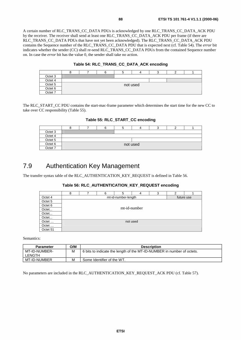
ETSI
ETSI TS 101 761-4 V1.1.1 (2000-06)88
A certain number of RLC_TRANS_CC_DATA PDUs is acknowledged by one RLC_TRANS_CC_DATA_ACK PDUby the receiver. The receiver shall send at least one RLC_TRANS_CC_DATA_ACK PDU per frame (if there areRLC_TRANS_CC_DATA PDUs that have not yet been acknowledged). The RLC_TRANS_CC_DATA_ACK PDUcontains the Sequence number of the RLC_TRANS_CC_DATA PDU that is expected next (cf. Table 54). The error bitindicates whether the sender (CC) shall re-send RLC_TRANS_CC_DATA PDUs from the contained Sequence numberon. In case the error bit has the value 0, the sender shall take no action.
Table 54: RLC_TRANS_CC_DATA_ACK encoding
8 7 6 5 4 3 2 1Octet 3Octet 4Octet 5Octet 6Octet 7
not used
The RLC_START_CC PDU contains the start-mac-frame parameter which determines the start time for the new CC totake over CC responsibility (Table 55).
Table 55: RLC_START_CC encoding
8 7 6 5 4 3 2 1Octet 3Octet 4Octet 5Octet 6Octet 7
not used
7.9 Authentication Key ManagementThe transfer syntax table of the RLC_AUTHENTICATION_KEY_REQUEST is defined in Table 56.
Table 56: RLC_AUTHENTICATION_KEY_REQUEST encoding
8 7 6 5 4 3 2 1Octet 4 mt-id-number-length future useOctet 5Octet 6Octet...Octet...Octet...
mt-id-number
Octet …Octet …Octet 51
not used
Semantics:
Parameter O/M DescriptionMT-ID-NUMBER-LENGTH
M 6 bits to indicate the length of the MT-ID-NUMBER in number of octets.
MT-ID-NUMBER M Some Identifier of the WT.
No parameters are included in the RLC_AUTHENTICATION_KEY_REQUEST_ACK PDU (cf. Table 57).

ETSI
ETSI TS 101 761-4 V1.1.1 (2000-06)89
Table 57: RLC_AUTHENTICATION_KEY_REQUEST_ACK encoding
Table 57 shows the encoding of the RLC_AUTHENTICATION_KEY_TRANSFER PDU.
Table 58: RLC_AUTHENTICATION_KEY_TRANSFER encoding
Semantics:
Parameter O/M DescriptionVALID-KEY M 1 bits that equals 1 if the key is valid.
AUTH-KEY-LENGTH M Length of the AUTHENTICATION KEY in number of octets (6 bits).
PIN-CODE-LENGTH M Length of the PIN code of the subnet in number of octets (6 bits).
AUTH-KEY M Common AUTHENTICATION-KEY of the subnet. The length of the field can varyfrom 0 to 46 octets.
PIN-CODE M PIN code of the network in binary format, encoded with the Secret Session Key(SSK). The length of the field can vary from 0 to 23 octets.
RLC_AUTHENTICATION_KEY_TRANFER_ACK is defined in Table 59.
Table 59: RLC_AUTHENTICATION_KEY_TRANSFER_ACK encoding
8 7 6 5 4 3 2 1Octet 3Octet 4Octet 5Octet 6Octet 7
Not used
8 7 6 5 4 3 2 1Octet 4 valid-key auth-key-length Future Use
Octet 5 pin-code-length future useOctet 6Octet...
auth-key
Octet...Octet...
pin-code
Octet …Octet …Octet 51
not used
8 7 6 5 4 3 2 1valid-key future use
Octet 4Octet 5Octet 6Octet...Octet 19
md5-of-auth-key
Octet 20Octet …Octet …Octet 51
not used
ETSI
ETSI TS 101 761-4 V1.1.1 (2000-06)90
Semantics:
Parameter O/M DescriptionVALID-KEY M 1 bits that equals 1 if the key is valid.MD5-OF-AUTH-KEY M Hash value of the AUTH-KEY, generated with the MD5 algorithm
8 Service PrimitivesThe following clauses define the service primitives exchanged between the RLC and CL layers within a H/2-HD. Theadditions to the RLC basic specification (TS 101 761-2 [2]) which are needed to meet the home environmentrequirements are documented.
8.1 Primitive typesFour primitive types may be used:
- req (request), for a higher layer to request service from a lower layer;
- cnf (confirm), for the layer providing the service to confirm that the activity has been completed;
- ind (indication), for a layer providing a service to notify the next higher layer of any specific service relatedactivity;
- rsp (response), for a layer to acknowledge receipt of an indication primitive from the next lower layer.
The defined types for each category of primitive are shown as a list in curly brackets.
NOTE: These primitives are defined only for the purpose of describing layer-to-layer interactions. The primitivesare defined as an abstract list of parameters, and their concrete realization may vary betweenimplementations. No formal testing of primitives is intended. The following primitive definitions have nonormative significance.
8.2 Common DLC C-SAP Primitives to Convergence LayerThis subclause summarizes the common primitives between the convergence layer and the RLC layer whose realizationis required for any supported CL.

ETSI
ETSI TS 101 761-4 V1.1.1 (2000-06)91
DLC C-SAPPrimitives
RLC Primitives
Convergence Layer
RLC protocol Rad
ioLi
nkC
ontr
olsu
blay
er
DLCConnection
Control
AssociationControl
RadioResource
Control
Figure 32: Reference Model of protocol primitives
The common primitives at the DLC C-SAP have a correspondence to a subset of the RLC primitives defined inTS 101 761-2 [2] and in the present document. The parameters used in the common primitives at the DLC C-SAP areequal to or a subset of the RLC parameters defined there.
One DLC C-SAP common primitive may correspond to one of possibly several RLC primitives. It is the task of the RLCfunctions to control the relation between DLC C-SAP primitives and the RLC primitives. The RLC functions invoke theRLC primitives with appropriate parameters. (E.g. a request from the CL to set up 8 connections may result in 2subsequent connection setup sequences at the RLC level, each setting up 4 connections).
At the CC the MAC ID is used to distinguish between different RLC instances. Each CC-capable WT therefore has tosupport different RLC instances. A basic WT, however, only needs one RLC.
Realization of the following common DLC C-SAP primitives with their corresponding RLC primitives is necessary forall H/2-HDs:

ETSI
ETSI TS 101 761-4 V1.1.1 (2000-06)92
Table 60: DLC and corresponding RLC primitives
DLC C-SAP primitive RLC primitiveDLC_Setup - { req, ind }; DUC_SETUP - { req, ind };
DM_SETUP - { req, ind };DLC_CONNECT - { req, cnf, ind, rsp }; DUC_CONN - { req, cnf, ind, rsp };
DM_CONN - { req, cnf, ind, rsp };DLC_RELEASE - { req, cnf, ind, rsp }; DUC_RELEASE - { req, cnf, ind, rsp };
DM_RELEASE - { req, cnf, ind, rsp };DLC_MODIFY - { req, cnf, ind, rsp }; DUC_MODIFY - { req, cnf, ind, rsp };
DM_MODIFY - { req, cnf, ind, rsp };DLC_MULTICAST_JOIN - { req, cnf, ind, rsp }; ACF_GROUP_JOIN - { req, cnf, ind, rsp };DLC_MULTICAST_LEAVE - { req, ind }; ACF_GROUP_LEAVE - { req, cnf, ind, rsp };DLC_MULTICAST_CONNECT - { req, cnf, ind, rsp }; DM_Multicast CONN - { req, cnf, ind, rsp };DLC_MULTICAST_RELEASE - { req, cnf, ind, rsp }; DM_Multicast RELEASE - { req, cnf, ind, rsp };DLC_MULTICAST_MODIFY - { req, cnf, ind, rsp }; DM_Multicast MODIFY - { req, cnf, ind, rsp };DLC_CL_BROADCAST_JOIN - { req, cnf, ind, rsp }; ACF_CL_BROADCAST_JOIN - {req, cnf, ind, rsp};DLC_INFO_TRANSFER - { req, cnf, ind, rsp }; ACF_INFO - { req, cnf, ind, rsp };CCH_start_cl_ho – { ind, rsp }; CCH_start_cl_ho – { ind, rsp };CCH_start_cc – {ind, rsp}; CCH_start_cc – {ind, rsp};
NOTE: One DLC C-SAP primitive may correspond to one of possibly several RLC primitives. It is the task of the RLCfunctions (ACF and DCC) to control the relation between DLC C-SAP primitives and the RLC primitives. TheRLC functions invoke the RLC primitives with appropriate parameters.
8.3 Special DLC-C SAP Primitives to 1394 Convergence LayerIf the 1394 CL is to be supported by the H/2 DLC home extension, the following 1394 CL specific DLC C-SAPprimitives shall be realized in the concerned H/2-HDs. These two 1394-specific primitives are defined to imply thatsome special H/2 DLC services shall be provided to the 1394 CL locally in a H/2-HD. There is no peer-to-peer RLCmessage associated with them.
1394 CL-specific DLC C-SAP primitiveDLC_MAC_FRAME_START - { ind};
DLC_MAC_FRAME_NUMBER { ind};
The realization of DLC_MAC_FRAME_START is necessary to enable 1394 Cycle Clock propagation from a WCM(Wireless Cycle Master) to all other H/2-HDs, where the WCM can be any H/2-HD in the subnet.
DLC_MAC_FRAME_START shall realize a time reference event, which shall be generated as a hardware impulse atthe end of the 16 µs broadcast burst preamble TS 101 475 [3]. The processing delay between the assertion of thisimpulse to the 1394 CL and the end of the broadcast burst preamble shall be a constant, which is known to the 1394 CL.After a calibration of the processing delay, DLC_MAC_FRAME_START is used as a reference event to trigger all H/2-HDs supporting 1394 CL to read and store the local 1394 CTR (Cycle Time Register) value at the same time. The stored1394 CTR value will be compared to that of the WCM, which is multicast in a LCH by the WCM to all other H/2 based1394 devices in each MAC frame, in order to correct the deviation to the WCM CTR (TS 101 493-3-1 andTS 101 493-3-2 see Bibliography)).
NOTE: DLC_MAC_FRAME_START could be directly realized by a HW signal from the PHY layer.
DLC_MAC_FRAME_NUMBER primitive contains the current MAC frame counter value obtained from the BCCH. Itshall be sent to the IEEE 1394 CL in a way, that the current MAC frame counter value is available in the IEEE 1394 CLnot later than the end of the FCCH phase. The current MAC frame counter value will be included into the CTRadjustment protocol PDU in TS 101 493-3-1 and TS 101 493-3-2 (see Bibliography).

ETSI
ETSI TS 101 761-4 V1.1.1 (2000-06)93
Annex A (normative):PDU TypesThe basic WT and CC-capable columns indicate, whether the PDU is Mandatory or Optional to implement in basic WTsor CC-capable H/2-HDs. The PDU can be mandatory for both the sender and the receiver or the other peer only. If aPDU is mandatory for the sender, the sender shall be able to encode the PDU and send it at the correct time according tothe present document. If the PDU is mandatory for the receiver, it shall be able to decode the PDU and perform therequested actions according to the present document. If the PDU is optional, the sender may not be able to encode or useit. If the PDU is optional the receiver may not be able to decode the PDU, but the receiver shall be able to send thecorresponding RLC_NO_SUPPORT message TS 101 761-2 [2].
Table A.1: HE LCH PDU messages
LCH PDU type RLC message name BasicWT
CC-capable
(0000 0001) 1 RLC_CALIBRATION_REPORT M M2 RLC_DM_MC_SETUP O M3 RLC_DM_MC_CONNECT O M4 RLC_DM_MC_CONNECT_ACK O M5 RLC_DM_MC_CONNECT_COMPLETE O M6 RLC_ DM_MC_CONNECT_COMPLETE_ACK O M7 RLC_DM_MC_RELEASE O M8 RLC_ DM_MC_RELEASE_ACK O M9 RLC_DM_MC_MODIFY O M10 RLC_DM_MC_MODIFY_ACK O M11 RLC_TRANS_CC_DATA - O12 RLC_AUTHENTICATION_KEY_REQUEST M M13 RLC_AUTHENTICATION_KEY_TRANSFER M M
Table A.2: HE SCH PDU messages
SCH PDU type RLC message name BasicWT
CC-capable
(0000 0001) 1 RLC_DM_POWER_CONTROL M M2 RLC_CALIBRATION_MEASUREMENT_TRIGGER M M3 RLC_ CALIBRATION_MEASUREMENT M M4 RLC_CALIBRATION_REPORT_TRIGGER M M5 RLC_SHORT_CALIBRATION_REPORT M M6 RLC_CALIBRATION_LINKQUALITYMAP_REQUEST M M7 RLC_ CALIBRATION_LINKQUALITYMAP M M8 RLC_CC_HO_REQUEST - O9 RLC_CC_HO_REQUEST_ACK - O10 RLC_CC_HO_NOTIFY M M11 RLC_TRANS_CC_DATA_ACK - O12 RLC_START_CC - O13 RLC_START_CC_ACK - O14 RLC_CC_START_OPERATION M M15 RLC_AUTHENTICATION_KEY_REQUEST_ACK M M16 RLC_AUTHENTICATION_KEY_TRANSFER_ACK M M

ETSI
ETSI TS 101 761-4 V1.1.1 (2000-06)94
Annex B (normative):Parameter Types
WT-TX-LEVEL::= TX-LEVELADJUST-TX::= ENUMERATED{
no-adjust (0),m3dbm (1),m6dbm (2),m9dbm (3),m12dbm (4),m15dbm (5),m18dbm (6),m21dbm (7),p3dbm (9),p6db (10),p9dbm (11),p12dbm (12),p15dbm (13),p18dbm (14),p21dbm (15) }
AGE-OF-RSS::= ENUMERATED {last100ms (0),last250ms (1),last500ms (2),last1000ms (3) }
AUTH-KEY::= OCTET STRING(SIZE(0..46))
AUTH-KEY-LENGTH::= INTEGER(0..46)CAL-REPORT::= SEQUENCE {
mac-id MAC-ID,rss2-value RSS2-VALUE }
CAL-REPORT-LIST::= SEQUENCE(SIZE(0..23)) OF CAL-REPORTCOMPLETE-REPORT::= SEQUENCE {
mac-id MAC-ID,rss-report-list RSS-REPORT-LIST }
COMPLETE-REPORT-LIST::= SEQUENCE OFCOMPLETE-REPORTDATA::= OCTET STRING (SIZE(0..47))
DM-DUC-TYPE::= ENUMERATED {unicast (0),mutli-broadcast (1) }
description
EXT-IND::= ENUMERATED{data-end (0),data-continue (1)}
FRAME-COUNT::= INTEGER(0..16)MAC-IDS::= SEQUENCE (SIZE(0..3)) OFMAC-IDMAP-EXT-IND::= ENUMERATED{
map-end (0),map-continue (1)}
MT-ID-NUMBER-LENGTH::=INTEGER(1..32)
PIN-CODE::= OCTET STRING(SIZE(0..23))PIN-CODE-LENGTH::= INTEGER(0..23)REP-BUF-STATUS::= ENUMERATED {
reports-transmtted (0),reports-in-buffer (1) }
description
REPETITION-COUNTER::= INTEGER(0..4096)

ETSI
ETSI TS 101 761-4 V1.1.1 (2000-06)95
REQUEST-TYPE::= ENUMERATED {whole-map (0),mac-id-map (1) }
RR-FLAG::= ENUMERATED {receive-not-ready (0),receive-ready (1) }
RSS2-VALUE::= INTEGER(0..63)
RSS-REPORT::= SEQUENCE {mac-id MAC-ID,age-of-rss AGE-OF-RSS,rss2-value RSS2-VALUE }
RSS-REPORT-LIST::= SEQUENCE OFRSS-REPORT
SEQUENCE-NUMBER::= INTEGER(0..1024)START-MAC-FRAME::= SEQUENCE {
repetition-counter REPETITION-COUNTER,
frame-count FRAME-COUNT }TRIGGER-TYPE::= ENUMERATED {
all-wts (0),one-wt (1),one-wt (2),one-wt (3) }
2 bits that indicate if one, two, three or all WTsare triggered:00� All WTs are triggered (no MAC-IDincluded)01� One WT is triggered10� Two WTs are triggered11� Three WTs are triggered
VALID-KEY::= ENUMERATED{key-not-valid (0),key-valid (1)}

ETSI
ETSI TS 101 761-4 V1.1.1 (2000-06)96
Annex C (normative):RLC TIMERSManagement of RLC timers is described in TS 101 761-2 [2]. There are three different timers:
• T_short;
• T_medium;
• T_long.
The following new timers are defined in the present document:
Table C.1: H/2-HD Timers
H/2-HD ValueT_dm_mc_setup_wt T_shortT_dm_mc_connect_wt T_shortT_dm_mc_modify_req_wt T_shortT_dm_mc_release_wt T_shortT_dm_mc_power_control T_longT_dm_mc_setup_cc T_shortT_dm_mc_connect_cc T_shortT_dm_mc_connect_cmpt_cc T_shortT_dm_mc_modify_cc T_shortT_dm_mc_release_cc T_shortT_cc_ho_request_cc T_shortT_trans_cc_data_cc 6 msecT_start_cc_cc T_shortT_dm_mc_connect_ack_wt 4max_setup_time frames
T_trigger_lifetime 50 msec

ETSI
ETSI TS 101 761-4 V1.1.1 (2000-06)97
Annex D (informative):Informative SDL FSMs concerning Power Control
NOTE: The assumption in the model below is that the connection setup procedure between two WTs is split intoconnection setup between the CC and the first WT (WT1), and connection setup between the CC and thesecond WT (WT2). Only the connection setup with the second WT is represented since it does not dependon whether the connection was CC_initiated or WT_initated.
Connection_Setup_to_WT2
Connectivity_Check
RLC_DM_CONNECT NACK_from_WT1
NACK_from_WT2
T1
RLC_DM_CONNECT_ACK i=0 i=0
RLC_DM_CONNECT_COMPLETE_to_WT1
RG_to_WT1
i:=i-1 i:=i-1RLC_DM_CONNECT_COMPLETE_to_WT2
RG_to_WT2RG_to_WT2
RG_to_WT1
SET (T1)
SET (T1) SET (T1) SET (T2)
i:=MAX_TRIES
- Disconnected - Disconnected Wait_For_First_Ack
Connectivity_Check
Wait_For_First_Ack
RLC_DM_CONNECT_COMPLETE_ACK_from_WT1
RLC_DM_CONNECT_COMPLETE_ACK_from_WT2
T2
Wait_For_Second_Ack
Disconnected
Wait_For_Second_Ack
RLC_DM_CONNECT_COMPLETE_ACK_from_WT1
RLC_DM_CONNECT_COMPLETE_ACK_from_WT2
T2
Connected Disconnected
False
True
False
True
Figure D.1: Power Control – Connectivity Check – CC side

ETSI
ETSI TS 101 761-4 V1.1.1 (2000-06)98
Connection_Setup_of_WT2
Connectivity_Check
RLC_DM_CONNECT_ACK RG_to_this_WT
RG_to_peer_WT
RLC_DM_POWER_CONTROL_to_peer_WT
SET (T1)
Connectivity_Check
- Wait_for_PC_message
Wait_for_PC_message
RLC_DM_POWER_CONTROL_from_peer_WT
RG_to_peer_WT
T1 RG_to_this_WT
SET (T1) NACK_to_CC
RLC_DM_POWER_CONTROL_to_peer_WT
ait_Connection_Complete_mess
- - -
ait_Connection_Complete_mess
RLC_DM_CONNECT_COMPLETE RLC_DM_POWER_CONTROL_from_peer_WT
RG_to_this_WT
RLC_DM_CONNECT_COMPLETE_ACK RLC_DM_POWER_CONTROL_to_peer_WT
Connected - -
Figure D.2: Power Control – Connectivity Check – WT side

ETSI
ETSI TS 101 761-4 V1.1.1 (2000-06)99
Annex E (informative):SDL FSMs concerning Calibration
NOTE: The following FSMs are only informative. Their aim is to explain the basic idea of how calibration andpower control work, rather than to give algorithms ready to be implemented.
Calibration – CC side
Idle
Start_Measurement Start_Report T1 T3
RLC_CALIBRATION_MEASUREMENT_TRIGGER RLC_CALIBRATION_REPORT_TRIGGER
Set (T1) Set (T1) Idle Idle
Nbr_Triggered:=easurement_Triggered_WTs
This is a parameter of themeas. trigger message
Nbr_Tiggered:=Report_triggered_WTs
This is a parameter of therep. trigger message
Nbr_Granted:=0 Nbr_Granted:=0
SET (T3) T3 expires at the beginningof the next mac frame
SET (T3) T3 expires at the beginningof the next mac frame
Measurement Report
Figure E.1: Calibration CC side – page 1
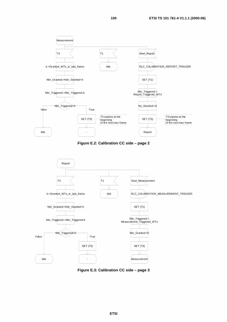
ETSI
ETSI TS 101 761-4 V1.1.1 (2000-06)100
Measurement
T3 T1 Start_Report
k:=Granted_WTs_in_last_frame Idle RLC_CALIBRATION_REPORT_TRIGGER
Nbr_Granted:=Nbr_Granted+k SET (T1)
Nbr_Triggered:=Nbr_Triggered-k Nbr_Triggered:=Report_Triggered_WTs
Nbr_Triggered>0 No_Granted:=0
SET (T3)T3 expires at thebeginningof the next mac frame
SET (T3)T3 expires at thebeginningof the next mac frame
Idle - Report
Truefalse
Figure E.2: Calibration CC side – page 2
Report
T3 T1 Start_Measurement
k:=Granted_WTs_in_last_frame RLC_CALIBRATION_MEASUREMENT_TRIGGER
Nbr_Granted:=Nbr_Granted+k SET (T1)
Nbr_Triggered:=Nbr_Triggered-k Nbr_Triggered:=Measurement_Triggered_WTs
Nbr_Triggered>0 Nbr_Granted:=0
SET (T3) SET (T3)
Idle -
Idle
Measurement
TrueFalse
Figure E.3: Calibration CC side – page 3

ETSI
ETSI TS 101 761-4 V1.1.1 (2000-06)101
Calibration – WT side
Idle
RLC_CALIBRATION_MEASUREMENT_TRIGGER RLC_CALIBRATION_REPORT_TRIGGER RG
SET (T4) SET (T5)
-Measurement Report
Figure E.4: Calibration WT side – page 1
Measurement
RLC_CALIBRATION_MEASUREMENT_TRIGGER RLC_CALIBRATION_REPORT_TRIGGER
SET (T4) T4 RG SET (T5)
- Idle Report
This trigger is for TRIGGERED_MACID WT This RG is for GRANTED_MACID WT
(TRIGGERED_MACID=WT_MACID)AND
(GRANTED_MACID=WT_MACID)
TRIGGERED_MACID=
GRANTED_MACIDRLC_CALIBRATION_MEASUREMENT
Measurement_and_update_of_local_RSS_table
MeasurementMeasurement Measurement
FalseTrue
True False
Figure E.5: Calibration WT side – page 2

ETSI
ETSI TS 101 761-4 V1.1.1 (2000-06)102
Report
RLC_CALIBRATION_REPORT_TRIGGER RLC_CALIBRATION_MEASUREMENT_TRIGGER
SET (T5) T5 RG SET (T4)
- Idle Measurement
This trigger is for TRIGGERED_MACID WT This RG is for GRANTED_MACID WT
(TRIGGERED_MACID=WT_MACID)AND
(GRANTED_MACID=WT_MACID)
TRIGGERED_MACID=
GRANTED_MACIDRLC_CALIBRATION_REPORT
Update_of_local_RSS_table
ReportReport Report
FalseTrue
True False
Figure E.6: Calibration WT side – page 3
ETSI
ETSI TS 101 761-4 V1.1.1 (2000-06)103
Annex F (informative):Specification of the CC Probing Process in SDLThe dynamic CC Selection has to prevent different CC-capable devices from becoming CC at the same time. Thecollision resolution mechanism is realized by the CC Probing and Frequency Scan processes that are defined insubclause 6.7. Both processes are described by a SDL specification which is depicted in Figure F.1 to Figure F.4 anddocumented within this annex.
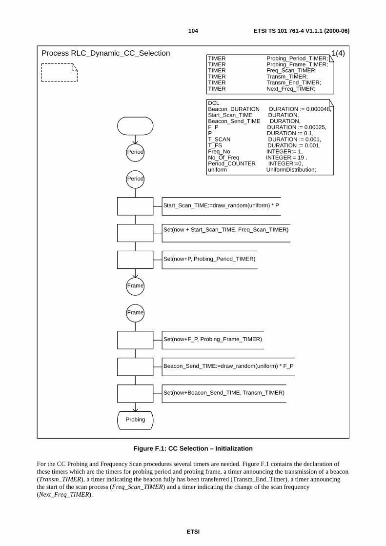
ETSI
ETSI TS 101 761-4 V1.1.1 (2000-06)104
Process RLC_Dynamic_CC_Selection 1(4)TIMER Probing_Period_TIMER;TIMER Probing_Frame_TIMER;TIMER Freq_Scan_TIMER;TIMER Transm_TIMER;TIMER Transm_End_TIMER;TIMER Next_Freq_TIMER;
DCLBeacon_DURATION DURATION := 0.000048,Start_Scan_TIME DURATION,Beacon_Send_TIME DURATION,F_P DURATION := 0.00025,P DURATION := 0.1,T_SCAN DURATION := 0.001,T_FS DURATION := 0.001,Freq_No INTEGER:= 1,No_Of_Freq INTEGER:= 19 ,Period_COUNTER INTEGER:=0,uniform UniformDistribution;
Period
Period
Start_Scan_TIME:=draw_random(uniform) * P
Set(now + Start_Scan_TIME, Freq_Scan_TIMER)
Set(now+P, Probing_Period_TIMER)
Frame
Frame
Set(now+F_P, Probing_Frame_TIMER)
Beacon_Send_TIME:=draw_random(uniform) * F_P
Set(now+Beacon_Send_TIME, Transm_TIMER)
Probing
Figure F.1: CC Selection – Initialization
For the CC Probing and Frequency Scan procedures several timers are needed. Figure F.1 contains the declaration ofthese timers which are the timers for probing period and probing frame, a timer announcing the transmission of a beacon(Transm_TIMER), a timer indicating the beacon fully has been transferred (Transm_End_Timer), a timer announcingthe start of the scan process (Freq_Scan_TIMER) and a timer indicating the change of the scan frequency(Next_Freq_TIMER).

ETSI
ETSI TS 101 761-4 V1.1.1 (2000-06)105
Within the declaration the CC selection parameters are also defined and initialized according to the reference valuesintroduced in subclause 6.7.3.1. The first phase of the CC Probing process is the initialization of the probing periodintroduced by the Period connector. The second phase of the CC Probing is the initialization of the probing frameintroduced by the Frame connector.
Process RLC_Dynamic_CC_Selection 2(4)/* CC/MT Selection Specification */
Probing
Transm_TIMER Beacon Freq_Scan_TIMER
Back_off Set(now+(T_SCAN+T_FS),Next_Freq_TIMER)
Set(now+Beacon_DURATION,Transm_End_TIMER)
Freq_No := 1;
Send_Beacon switch_freq
Freq_Scan
Probing
Probing_Period_TIMER Probing_Frame_TIMER
Period_Counter:=Period_Counter+1
Frame
Period_Counter>=10
Period
CC_Operation
false
true
Figure F.2: CC Selection – Probing state
In the state Probing several signals can be expected, see Figure F.2. A "Probing_Period_Timer" signal indicates thebeginning of a new probing period, a Probing_Frame_TIMER signal indicates the beginning of a new probing frame(virtual frame, not identically to the MAC frame). The reception of a beacon signal from another CC-capable terminalinduces the terminal to leave the probing process and to accept the other terminal as CC candidate. The Transm_TIMERsignal is received if the next beacon has to be sent. In this case the timer Transm_End_TIMER is started. Another signalwhich can occur is the Freq_Scan_TIMER indicating the beginning of a new frequency scan period. The probingprocess is finished if the Period_COUNTER expires. In this case the terminal becomes a CC.
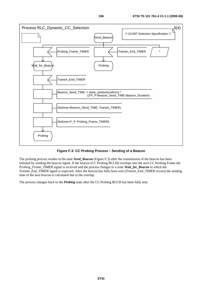
ETSI
ETSI TS 101 761-4 V1.1.1 (2000-06)106
Process RLC_Dynamic_CC_Selection 3(4)/* CC/MT Selection Specification */
Send_Beacon
Probing_Frame_TIMER Transm_End_TIMER *
Wait_for_Beacon Probing
Transm_End_TIMER
Beacon_Send_TIME := draw_random(uniform) *(2*F_P-Beacon_Send_TIME-Beacon_Duration)
Set(now+Beacon_Send_TIME, Transm_TIMER)
Set(now+F_P, Probing_Frame_TIMER)
Probing
Figure F.3: CC Probing Process – Sending of a Beacon
The probing process resides in the state Send_Beacon (Figure F.3) after the transmission of the beacon has beeninitiated by sending the beacon signal. If the beacon (CC Probing BCCH) overlaps into the next CC Probing Frame theProbing_Frame_TIMER signal is received and the process changes to a state Wait_for_Beacon in which theTransm_End_TIMER signal is expected. After the beacon has fully been sent (Transm_End_TIMER occurs) the sendingtime of the next beacon is calculated due to the overlap.
The process changes back to the Probing state after the CC Probing BCCH has been fully sent.
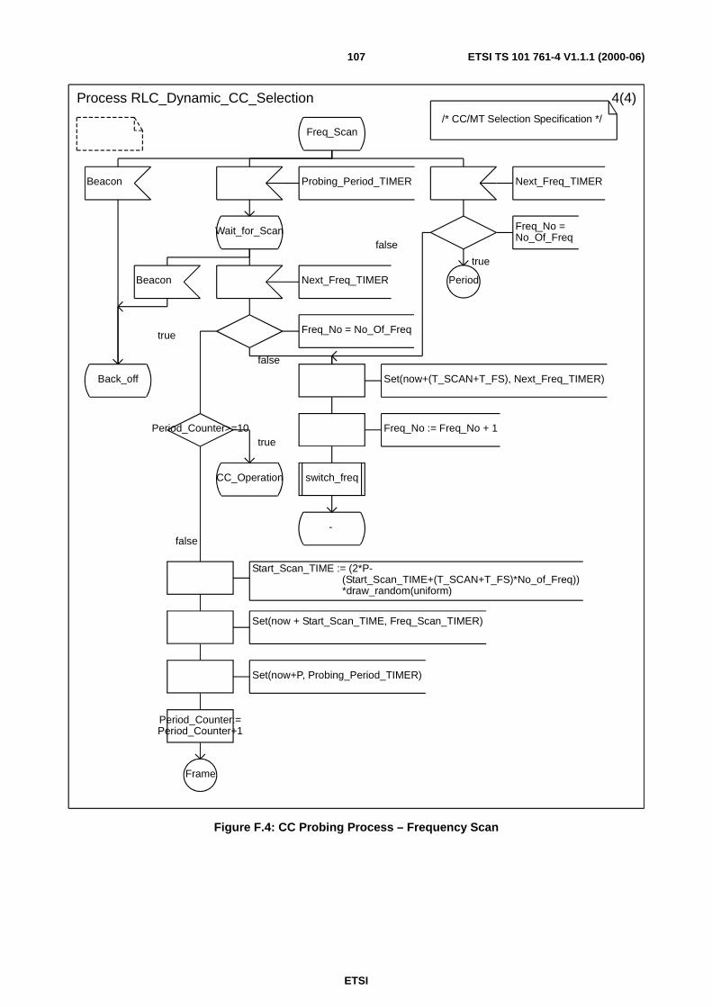
ETSI
ETSI TS 101 761-4 V1.1.1 (2000-06)107
Process RLC_Dynamic_CC_Selection 4(4)/* CC/MT Selection Specification */
Freq_Scan
Beacon Probing_Period_TIMER Next_Freq_TIMER
Wait_for_Scan Freq_No =No_Of_Freq
Beacon Next_Freq_TIMER Period
Freq_No = No_Of_Freq
Back_off Set(now+(T_SCAN+T_FS), Next_Freq_TIMER)
Period_Counter>=10 Freq_No := Freq_No + 1
CC_Operation switch_freq
-
Start_Scan_TIME := (2*P-(Start_Scan_TIME+(T_SCAN+T_FS)*No_of_Freq))*draw_random(uniform)
Set(now + Start_Scan_TIME, Freq_Scan_TIMER)
Set(now+P, Probing_Period_TIMER)
Period_Counter:=Period_Counter+1
Frame
true
false
false
true
true
false
Figure F.4: CC Probing Process – Frequency Scan

ETSI
ETSI TS 101 761-4 V1.1.1 (2000-06)108
The frequency scan (Figure F.4) is started periodically whereby the start time is determined by random. The start time ofthe last frequency scan has been stored in the variable Start_Scan_TIME. To generate the start time of the next scanningperiod it has to be evaluated if the scanning period overlaps into the following probing period. In this case theProbing_Period_TIMER is received during the scanning period. The process changes to the Wait_for_Scan state. Thescan procedure finishes equaly with a non-overlapping scan process. Afterwards the starting time of the next frequencyscanning is calculated. The process is then continued at the probing frame initialization which is symbolized by the"Frame" connector. If a beacon signal is received the terminal leaves the probing process and accepts the other terminalas CC candidate. The receipt of a Next_Freq_TIMER signal within the scan procedure (state Freq_Scan orWait_for_Scan) induces the process to change the operating frequency after the scanning duration T_SCAN. After all 19frequencies have been scanned the frequency scan is finished. It is not allowed to scan the frequency channels in order.The index Freq_No shall be mapped randomly onto the different usable frequency channels. The receipt of aTransm_TIMER indicating the start of beacon transmission is ignored during the scan procedure.

ETSI
ETSI TS 101 761-4 V1.1.1 (2000-06)109
Annex G (informative):Specification of the CC Responsibility Handover Process inSDLIn this annex the SDL specification for the CC Responsibility Handover is presented. The primitive initiating the CCHandover called CCH_cc_ho_request_req is received in the Associated state within the current CC (Figure G.1). Uponreception of the primitive the RLC_CC_HO_REQUEST PDU is sent to all WTs in the subnet and the CC changes to thestate Central_Controller_Handover_Requested. In this state the RLC_CC_HO_REQUEST_ACK PDU is expected. Ifthis PDU comes in, the CCH_cc_ho_request_cnf primitive is sent to the RLC environment. Afterwards aRLC_CC_HO_NOTIFY PDU is sent to all WTs. This is represented in the SDL diagram by a loop fromMaxMacId to 0. If the signal has been sent to all WT MAC Ids the CCH_start_cl_ho_ind primitive is sent to all CLs andthe CC goes into the state RLC_Stopped.
PROCESS TYPE PTCC 1(4)
/* CC specific Specification */
TIMERT_cc_ho_req_cc;
DCLcount_mac INTEGER := MaxMacId,retransCounter INTEGER := MaxRetransmissions;
Exception
ASSOCIATED Central_Controller_Handover_Requested
CCH_cc_ho_request_req
RLC_CC_HO_REQUEST_ACK
T_cc_ho_req_cc CC HO failed,try another candidate
RLC_CC_HO_REQUEST
CCH_cc_ho_request_cnf
retransCounter= 0
SET(T_cc_ho_req_cc) RLC_CC_HO_NOTIFY
on DL RBCH RLC_CC_HO_REQUEST
Central_Controller_Handover_Requested
CCH_start_cl_ho_ind retransCounter:=retransCounter - 1
RESET(T_cc_ho_req_cc) SET(T_cc_ho_req_cc)
RLC_Stopped
Central_Controller_Handover_Requested
ASSOCIATED
Indication to CL
FalseTrue
Figure G.1: CC Responsibility Handover – SDL specification of CC, page 1
In the state RLC_stopped only the CC Handover procedure goes on at RLC level. The CC waits to receive the primitiveCCH_start_cl_ho_rsp from the environment. After reception of this primitive the CC first starts to release allconnections in CM of all WTs (see Figure G.2). If all connections in CM are released, the CC goes into the stateWait_for_ho_start.

ETSI
ETSI TS 101 761-4 V1.1.1 (2000-06)110
PROCESS TYPE PTCC 2(4)
/* CC specific Specification */ TIMERtiReleaseInd;
DCLMaxAckTime DURATION,DataAckTime DURATION;
RLC_Stopped
CCH_start_cl_ho_rsp
count_mac :=MaxMacId;
count_mac= 0
RLC_RELEASE(dlcc_id_list,release_cause) TO dlcc_id
Only DL/ULConnections
Wait_for_ho_start
All UL and DLConnectionsreleased
SET(Now+MaxAckTime,tiReleaseInd)
Release_Initiated
RLC_Release_ACK(dlcc_id_list)
tiReleaseInd
count_mac :=count_mac - 1;
FALSE
TRUE
Figure G.2: CC Responsibility Handover – SDL specification of CC, page 2
In the state Wait_for_ho_start, the CCH_start_cc_req primitive is expected. If it comes in, the data transfer procedure isstarted (Figure G.3). For the data transfer a Go-Back-N ARQ protocol is applied. The CC knows how manyRLC_CC_TRANS_CC_DATA PDUs are necessary to transmit all data to the CC-candidate. This number of PDUs isstored in the parameter pduToSend. The variable count_pduToSend in Figure 3 gives the number of PDUs that still haveto be sent in the course of the procedure. At the beginning of the data transfer count_pduToSend is set to the valuepduToSend. In each frame a certain number of RLC_TRANS_CC_DATA PDUs is transmitted in one packet train. Howmany PDUs are transmitted in a row is out of the scope of the present document. This is why the implementation of thefunction calcOptPduInARow is left open in Figure 3. Depending on how many PDUs still have to be send and probablyalso on the current traffic load the function calcOptPduInARow determines the value of the variable optPduInARow.Then the optPduInARow number of PDUs is transmitted by the loop that is controlled by the variable count_pduInRow.With each transmitted PDU the sequence number sn is incremented by 1. If the PDU is the last PDU of the whole datatransfer (count_pduInRow=1 and count_pduToSend=optPduInARow), then the ext_ind field is set to 0 (false).

ETSI
ETSI TS 101 761-4 V1.1.1 (2000-06)111
If all PDUs of the packet train have been transmitted, the CC sets a timer for the acknowledgement and goes to the stateData_Send. In this state either the RLC_TRANS_CC_DATA_ACK arrives or the timer runs out. In case theRLC_TRANS_CC_DATA_ACK has arrived, the CC checks whether the RR_flag included in the PDU is true or false.If the RR_flag is false, the CC retransmits from the signalled snAck number on (this is done by setting sn=snAck). If theRR_flag is true, this means that all PDUs up to snAck have been correctly received. In this case the CC just sets thecount_pduToSend parameter to the new value. It does not retransmit PDUs from snAck+1 on, but continues withtransmission of PDU sn (sn is unchanged). A special case occurs if snAck is equal to 0. This indicates that the lastRLC_TRANS_CC_DATA PDU of the whole procedure has been correctly received by the CC-candidate and that theCC can change to the state CC_Start_Initiated.
In case the timer for the acknowledgement (T_trans_cc_data_cc) runs out, the CC retransmits the last optPduInARowPDUs (this is done by setting sn=sn-optPduInARow).

ETSI
ETSI TS 101 761-4 V1.1.1 (2000-06)112
PROCESS TYPE PTCC 3(4)DCLsn INTEGER,snAck INTEGER,ext_ind BOOL,RR_flag BOOL,pduToSend INTEGER,optPduInARow INTEGER,count_pduToSend INTEGER,count_pduInRow INTEGER;
TIMERT_trans_cc_data_cc,T_start_cc_cc;
Wait_for_ho_start
CCH_start_cc_req
Send RLC-PDUs toCC Candidate viaGo Back-N ARQ sn := 1;
snAck := 1;
ext_ind:= TRUE;
count_pduToSend counts total number of unacknowledged PDUs
count_pduInRow counts remaining PDUs to be sent in a row
count_pduToSend:= pduToSend;
Communicate withMAC and calculatethe optimal pdunumber to be sentin a row (in one frame)
optPduInARow :=calcOptPduInARow(count_pduToSend)
count_pduInRow :=optPduInARow;
count_pduInRow
SET(Now+DataAckTime,T_trans_cc_data_cc)
RLC_TRANS_CC_DATA TOCC_CAND(sn, ext_ind)
optPduInARow =count_pduToSend
Data_Send
sn :=sn + 1;
ext_ind :=FALSE RLC_TRANS_
CC_DATA_ACK(snAck, RR_flag) T_trans_cc_data_cc
count_pduInRow :=count_pduInRow - 1;
RR_flag
snAck
RLC_START_CC
count_pduToSent :=count_pduToSent -
optPduInARow
count_pduToSend :=pduToSent -
snAck +1SET(T_start_cc_cc)
sn :=snAck;
sn := sn-optPduInARowCC_Start_
Initiated
0ELSE
1
ELSE
TRUE FALSE
0
ELSE
Figure G.3: CC Responsibility Handover – SDL specification of CC, page 3
In the state CC_Start_Initiated the RLC_START_CC_ACK PDU is expected from the CC-candidate (Figure G.4). Ifthis PDU arrives, the CC sends the CCH_start_cc_cnf primitive to the RLC environment, reables its RLC and becomes anormal WT.
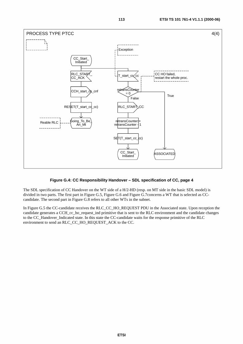
ETSI
ETSI TS 101 761-4 V1.1.1 (2000-06)113
PROCESS TYPE PTCC 4(4)
Exception
CC_Start_Initiated
RLC_START_CC_ACK
T_start_cc_cc CC HO failed,restart the whole proc.
CCH_start_cc_cnf retransCounter= 0
RESET(T_start_cc_cc) RLC_START_CC
Reable RLC Going_To_Be_An_Mt
retransCounter:=retransCounter - 1
SET(T_start_cc_cc)
CC_Start_Initiated
ASSOCIATED
FalseTrue
Figure G.4: CC Responsibility Handover – SDL specification of CC, page 4
The SDL specification of CC Handover on the WT side of a H/2-HD (resp. on MT side in the basic SDL model) isdivided in two parts. The first part in Figure G.5, Figure G.6 and Figure G.7concerns a WT that is selected as CC-candidate. The second part in Figure G.8 refers to all other WTs in the subnet.
In Figure G.5 the CC-candidate receives the RLC_CC_HO_REQUEST PDU in the Associated state. Upon reception thecandidate generates a CCH_cc_ho_request_ind primitive that is sent to the RLC environment and the candidate changesto the CC_Handover_Indicated state. In this state the CC-candidate waits for the response primitive of the RLCenvironment to send an RLC_CC_HO_REQUEST_ACK to the CC.
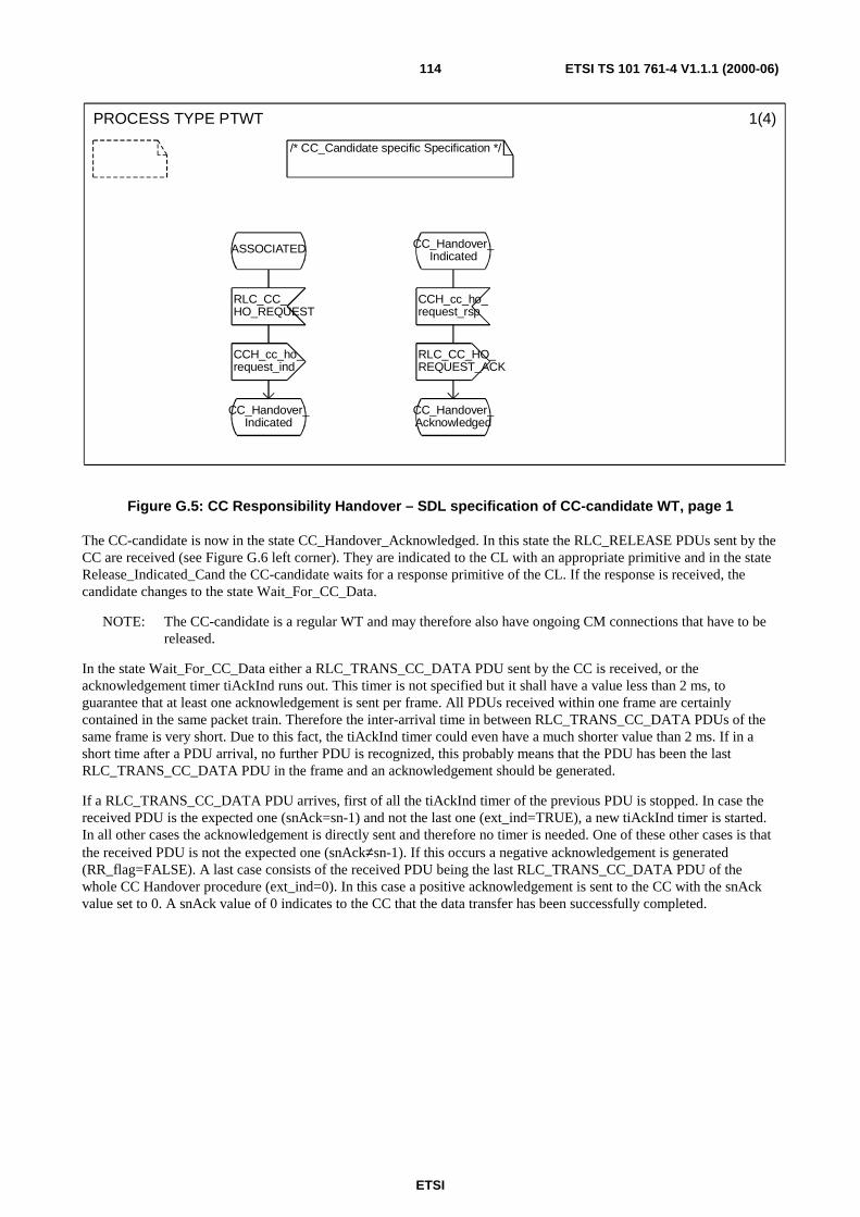
ETSI
ETSI TS 101 761-4 V1.1.1 (2000-06)114
PROCESS TYPE PTWT 1(4)
/* CC_Candidate specific Specification */
ASSOCIATED CC_Handover_Indicated
RLC_CC_HO_REQUEST
CCH_cc_ho_request_rsp
CCH_cc_ho_request_ind
RLC_CC_HO_REQUEST_ACK
CC_Handover_Indicated
CC_Handover_Acknowledged
Figure G.5: CC Responsibility Handover – SDL specification of CC-candidate WT, page 1
The CC-candidate is now in the state CC_Handover_Acknowledged. In this state the RLC_RELEASE PDUs sent by theCC are received (see Figure G.6 left corner). They are indicated to the CL with an appropriate primitive and in the stateRelease_Indicated_Cand the CC-candidate waits for a response primitive of the CL. If the response is received, thecandidate changes to the state Wait_For_CC_Data.
NOTE: The CC-candidate is a regular WT and may therefore also have ongoing CM connections that have to bereleased.
In the state Wait_For_CC_Data either a RLC_TRANS_CC_DATA PDU sent by the CC is received, or theacknowledgement timer tiAckInd runs out. This timer is not specified but it shall have a value less than 2 ms, toguarantee that at least one acknowledgement is sent per frame. All PDUs received within one frame are certainlycontained in the same packet train. Therefore the inter-arrival time in between RLC_TRANS_CC_DATA PDUs of thesame frame is very short. Due to this fact, the tiAckInd timer could even have a much shorter value than 2 ms. If in ashort time after a PDU arrival, no further PDU is recognized, this probably means that the PDU has been the lastRLC_TRANS_CC_DATA PDU in the frame and an acknowledgement should be generated.
If a RLC_TRANS_CC_DATA PDU arrives, first of all the tiAckInd timer of the previous PDU is stopped. In case thereceived PDU is the expected one (snAck=sn-1) and not the last one (ext_ind=TRUE), a new tiAckInd timer is started.In all other cases the acknowledgement is directly sent and therefore no timer is needed. One of these other cases is thatthe received PDU is not the expected one (snAck≠sn-1). If this occurs a negative acknowledgement is generated(RR_flag=FALSE). A last case consists of the received PDU being the last RLC_TRANS_CC_DATA PDU of thewhole CC Handover procedure (ext_ind=0). In this case a positive acknowledgement is sent to the CC with the snAckvalue set to 0. A snAck value of 0 indicates to the CC that the data transfer has been successfully completed.

ETSI
ETSI TS 101 761-4 V1.1.1 (2000-06)115
PROCESS TYPE PTWT 2(4)
/* CC_Candidate specific Specification */ DCLsn INTEGER := 1,snAck INTEGER := 0,ext_ind BOOL := FALSE,WaitForAckTime DURATION,RR_flag BOOL := TRUE,timerExists BOOL := FALSE;
TIMERtiAckInd;
/* set to less than 2 ms, becauseone ack per frame */
CC_Handover_Acknowledged
Release_indicated_Cand
Only DL/ULConnections
RLC_RELEASE(dlcc_id_list, release_cause)
DUC_release_rsp(DUC_RELEASE_ACK_ARG)
Wait_for_CC_Data
DUC_release_ind(DUC_RELEASE_ARG)
RLC_RELEASE_ACK(dlcc_id_list)
RLC_TRANS_CC_DATA(sn, ext_ind)
Release_indicated_Cand
Wait_For_CC_Data
timerExists
tiAckInd
Reset(tiAckInd)
RR_flag := TRUE;
RLC_TRANS_CC_DATA_ACK(snAck, RR_flag)
snAck = sn-1
-snAck :=snAck + 1
RR_flag := FALSE;
ext_ind
SET(Now+WaitForAckTime,tiAckInd)
snAck := 0;RR_flag := TRUE;
RLC_TRANS_CC_DATA_ACK(snAck, RR_flag)
timerExists :=TRUE
RLC_TRANS_CC_DATA_ACK(snAck,RR_flag)
timerExists :=FALSE
timerExists :=FALSE
- -
snAck := 1;snAck := 1;
ext_ind := FALSE;
Data_Send
TRUE
FALSE
TRUE FALSE
TRUE FALSE
Figure G.6: CC Responsibility Handover – SDL specification of CC-candidate WT, page 2
In the state Data_Send the CC-candidate waits for the RLC_START_CC PDU from the CC (Figure G.7). Uponreception of the PDU a CCH_start_cc_ind is sent to the environment. The environment responds with aCCH_start_cc_rsp while the CC-candidate RLC layer is in the state CC_Start_indicated. If the RLC receives theresponse of the environment it sends a RLC_START_CC_ACK PDU to the old CC and starts CC operation at therequested time. Furthermore a RLC_CC_START_OPERATION is sent out in broadcast mode to inform all WTs aboutthe take over of CC functionality.

ETSI
ETSI TS 101 761-4 V1.1.1 (2000-06)116
PROCESS TYPE PTWT 3(4)
/* WT specific Specification */
Data_Send CC_Start_Indicated
RLC_START_CC
CCH_start_cc_rsp
CCH_start_cc_ind
RLC_START_CC_ACK
CC_Start_Indicated
RLC_CC_START_OPERATION
CC_Started
Figure G.7: CC Responsibility Handover – SDL specification of CC-candidate WT, page 3
Figure G.8 finally gives an overview over the CC Handover specific processes inside a WT that is not a CC-candidate.After the reception of the RLC_CC_HO_NOTIFY PDU the WT goes into the state RLC_Stopped_MT. In this state theWT waits for the RLC_RELEASE requests for its CM connections. After indication and response to/from the CL, theWT changes to the state Connections_Released_MT. If no RLC_RELEASE requests are received, e.g. in the case wherethe WT only maintains DM connections, the WT directly changes to the state Connections_Released_MT after the timertiNoReleases has run out. In the state Connections_Released_MT the WT receives theRLC_CC_START_OPERATION message and goes back to its basic state Associated.

ETSI
ETSI TS 101 761-4 V1.1.1 (2000-06)117
PROCESS TYPE PTWT 4(4)
/* WT specific Specification */ DCLtiNoReleases DURATION;
ASSOCIATED RLC_Stopped_MT
RLC_CC_HO_NOTIFY
RLC_RELEASE(dlcc_id_list, release_cause)
tiNoReleases
SET(Now+MaxWaitTime,tiNoReleases)
DUC_release_ind(DUC_RELEASE_ARG)
Connections_Released_MT
RLC_Stopped_MT
Release_Indicated_MT
Release_Indicated_MT
Only DL/ULConnections
Connections_Released_MT
DUC_release_rsp(DUC_RELEASE_ACK_ARG)
RLC_CC_START_OPERATION
RLC_RELEASE_ACK(dlcc_id_list)
ASSOCIATED
Connections_Released_MT
Figure G.8: CC Responsibility Handover – SDL specification of WT

ETSI
ETSI TS 101 761-4 V1.1.1 (2000-06)118
Annex H (informative):Example of valid Reed-Solomon wordThe following RS word is built from 4 consecutive PDUs. These PDUs are normal LCH, hence the PDU-type is set to00. The sync field is inverted for the first PDU. The other bits of the first octet are set to zero. The contents of the otheroctets of the PDUs are explained in the table below.
PDU#1 PDU#2 PDU#3 PDU#4
PDU type 00 00 00 00
Sync field 11 00 00 00
Octet #ivalue
(from i=2 to50)
I 50+i 100+i 150+i
The following RS word has been obtained from these 4 PDUs payload with padding 39 0-bytes in front of the 200payload bytes and applying the RS(239,255). The redundancy is in bold.
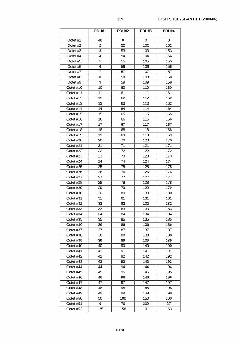
ETSI
ETSI TS 101 761-4 V1.1.1 (2000-06)119
PDU#1 PDU#2 PDU#3 PDU#4
Octet #1 48 0 0 0
Octet #2 2 52 102 152
Octet #3 3 53 103 153
Octet #4 4 54 104 154
Octet #5 5 55 105 155
Octet #6 6 56 106 156
Octet #7 7 57 107 157
Octet #8 8 58 108 158
Octet #9 9 59 109 159
Octet #10 10 60 110 160
Octet #11 11 61 111 161
Octet #12 12 62 112 162
Octet #13 13 63 113 163
Octet #14 14 64 114 164
Octet #15 15 65 115 165
Octet #16 16 66 116 166
Octet #17 17 67 117 167
Octet #18 18 68 118 168
Octet #19 19 69 119 169
Octet #20 20 70 120 170
Octet #21 21 71 121 171
Octet #22 22 72 122 172
Octet #23 23 73 123 173
Octet #24 24 74 124 174
Octet #25 25 75 125 175
Octet #26 26 76 126 176
Octet #27 27 77 127 177
Octet #28 28 78 128 178
Octet #29 29 79 129 179
Octet #30 30 80 130 180
Octet #31 31 81 131 181
Octet #32 32 82 132 182
Octet #33 33 83 133 183
Octet #34 34 84 134 184
Octet #35 35 85 135 185
Octet #36 36 86 136 186
Octet #37 37 87 137 187
Octet #38 38 88 138 188
Octet #39 39 89 139 189
Octet #40 40 90 140 190
Octet #41 41 91 141 191
Octet #42 42 92 142 192
Octet #43 43 93 143 193
Octet #44 44 94 144 194
Octet #45 45 95 145 195
Octet #46 46 96 146 196
Octet #47 47 97 147 197
Octet #48 48 98 148 198
Octet #49 49 99 149 199
Octet #50 50 100 150 200
Octet #51 6 76 209 27
Octet #52 125 158 101 163

ETSI
ETSI TS 101 761-4 V1.1.1 (2000-06)120
PDU#1 PDU#2 PDU#3 PDU#4
Octet #53 87 1 115 101
Octet #54 179 92 15 61
ETSI
ETSI TS 101 761-4 V1.1.1 (2000-06)121
BibliographyThe following material, though not specifically referenced in the body of the present document (or not publiclyavailable), gives supporting information.
ETSI TS 101 493-1: "Broadband Radio Access Networks (BRAN); HIPERLAN Type 2; Packet based ConvergenceLayer; Part 1: Common Part".
ETSI TS 101 493-2: "Broadband Radio Access Networks (BRAN); HIPERLAN Type 2; Packet based ConvergenceLayer; Part 2: Ethernet Service Specific Convergence Sublayer (SSCS)".
ETSI TS 101 493-3-1: "Broadband Radio Access Networks (BRAN); HIPERLAN Type 2; Packet based ConvergenceLayer; Part 3: IEEE 1394 Service Specific Convergence Sublayer (SSCS); Sub-part 1: Generic Functions".
ETSI TS 101 493-3-2: "Broadband Radio Access Networks (BRAN); HIPERLAN Type 2; Packet based ConvergenceLayer; Part 3: IEEE 1394 Service Specific Convergence Sublayer (SSCS); Sub-part 2: Bridge Specific Functions".
ETSI TS 101 763-1: "Broadband Radio Access Networks (BRAN); HIPERLAN Type 2; Cell based ConvergenceLayer; Part 1: Common Part".
ETSI TS 101 763-2: "Broadband Radio Access Networks (BRAN); HIPERLAN Type 2; Cell based ConvergenceLayer; Part 2: UNI Service Specific Convergence Sublayer (SSCS)".
ETSI TR 101 683 (V1.1): "Broadband Radio Access Networks (BRAN); HIPERLAN Type 2; System overview".
ETSI TR 101 031: "Broadband Radio Access Networks (BRAN); HIgh PErformance Radio Local Area Network(HIPERLAN) Type 2; Requirements and architectures for wireless broadband access".
ETSI TS 101 762: "Broadband Radio Access Networks (BRAN); HIPERLAN Type 2; Network Management".
ETSI TS 101 761-3: "Broadband Radio Access Networks (BRAN); HIPERLAN Type 2; Data Link Control (DLC)Layer; Part 3: Extension for Business and Public Environments".
ETSI
ETSI TS 101 761-4 V1.1.1 (2000-06)122
History
Document history
V1.1.1 June 2000 Publication


![TRANSPORTATION DEPARTMENT [761]](https://static.documents.pub/doc/80x56/61858e8b3fae02595c6f5634/transportation-department-761.jpg)
