ETSI TS 102 576 V2.1.1 (2016-02) Radio access network equipment specification; Mobile Communication On Board Aircraft (MCOBA) systems; Operational requirements and methodology for showing conformance TECHNICAL SPECIFICATION
Transcript
ETSI TS 102 576 V2.1.1 (2016-02)
Radio access network equipment specification; Mobile Communication On Board Aircraft (MCOBA) systems;
Operational requirements and methodology for showing conformance
TECHNICAL SPECIFICATION
ETSI
ETSI TS 102 576 V2.1.1 (2016-02)2
Reference RTS/MSG-TFES-31
Keywords GSM, LTE, MCOBA, radio, UMTS
ETSI
650 Route des Lucioles F-06921 Sophia Antipolis Cedex - FRANCE
Tel.: +33 4 92 94 42 00 Fax: +33 4 93 65 47 16
Siret N° 348 623 562 00017 - NAF 742 C
Association à but non lucratif enregistrée à la Sous-Préfecture de Grasse (06) N° 7803/88
Important notice
The present document can be downloaded from: http://www.etsi.org/standards-search
The present document may be made available in electronic versions and/or in print. The content of any electronic and/or print versions of the present document shall not be modified without the prior written authorization of ETSI. In case of any
existing or perceived difference in contents between such versions and/or in print, the only prevailing document is the print of the Portable Document Format (PDF) version kept on a specific network drive within ETSI Secretariat.
Users of the present document should be aware that the document may be subject to revision or change of status. Information on the current status of this and other ETSI documents is available at
http://portal.etsi.org/tb/status/status.asp
If you find errors in the present document, please send your comment to one of the following services: https://portal.etsi.org/People/CommiteeSupportStaff.aspx
Copyright Notification
No part may be reproduced or utilized in any form or by any means, electronic or mechanical, including photocopying and microfilm except as authorized by written permission of ETSI.
The content of the PDF version shall not be modified without the written authorization of ETSI. The copyright and the foregoing restriction extend to reproduction in all media.
DECTTM, PLUGTESTSTM, UMTSTM and the ETSI logo are Trade Marks of ETSI registered for the benefit of its Members. 3GPPTM and LTE™ are Trade Marks of ETSI registered for the benefit of its Members and
of the 3GPP Organizational Partners. GSM® and the GSM logo are Trade Marks registered and owned by the GSM Association.
4.1 Considerations for installation of Mobile Communication On Board Aircraft systems ..................................... 7
4.2 Maximum E.I.R.P. of the aircraft due to the Mobile Communication On Board Aircraft system ..................... 7
4.3 Derivation of the minimum power level of the NCU at the antenna input (Criterion A) ................................... 8
4.4 Derivation of the permitted maximum power level of the MCOBA system at the antenna input (Criterion B) ..................................................................................................................................................... 10
4.5 Derivation of the effective power level due to the UE onboard aircraft (Criterion C) ..................................... 10
5 Description of test methodology to derive key parameters .................................................................... 10
5.1 Cabin coupling loss .......................................................................................................................................... 10
5.1.1 General description of test set up ................................................................................................................ 10
5.1.3 Test purpose ................................................................................................................................................ 11
5.1.4 Test procedure ............................................................................................................................................ 11
5.2 Consideration for RF attenuation measurement on aircraft .............................................................................. 13
5.3 Aircraft attenuation in combination with the aircraft antenna system .............................................................. 14
5.3.1 Test purpose ................................................................................................................................................ 14
5.3.2 Methods of measurement ............................................................................................................................ 14
5.3.3 Calculation of combined effective aircraft attenuation and antenna system ............................................... 15
5.4 Attenuation of aircraft at window ..................................................................................................................... 16
5.4.1 Test purpose ................................................................................................................................................ 16
5.4.2 Methods of measurement ............................................................................................................................ 16
5.4.3 Calculation of aircraft attenuation at the window ....................................................................................... 17
Annex A (informative): System Description ........................................................................................ 20
A.1 High level System Description ............................................................................................................... 20
A.4 Antenna system ...................................................................................................................................... 21
A.5 Antenna system installation .................................................................................................................... 21
Annex B (informative): Bibliography ................................................................................................... 22
History .............................................................................................................................................................. 23
ETSI
ETSI TS 102 576 V2.1.1 (2016-02)4
Intellectual Property Rights IPRs essential or potentially essential to the present document may have been declared to ETSI. The information pertaining to these essential IPRs, if any, is publicly available for ETSI members and non-members, and can be found in ETSI SR 000 314: "Intellectual Property Rights (IPRs); Essential, or potentially Essential, IPRs notified to ETSI in respect of ETSI standards", which is available from the ETSI Secretariat. Latest updates are available on the ETSI Web server (https://ipr.etsi.org/).
Pursuant to the ETSI IPR Policy, no investigation, including IPR searches, has been carried out by ETSI. No guarantee can be given as to the existence of other IPRs not referenced in ETSI SR 000 314 (or the updates on the ETSI Web server) which are, or may be, or may become, essential to the present document.
Foreword This Technical Specification (TS) has been produced by ETSI Technical Committee Mobile Standards Group (MSG).
Modal verbs terminology In the present document "shall", "shall not", "should", "should not", "may", "need not", "will", "will not", "can" and "cannot" are to be interpreted as described in clause 3.2 of the ETSI Drafting Rules (Verbal forms for the expression of provisions).
"must" and "must not" are NOT allowed in ETSI deliverables except when used in direct citation.
Introduction The present document defines operational requirements and the methodology for showing conformance to the operational requirements for a Mobile Communication Onboard Aircraft system (MCOBA) whose essential requirements are defined in the ETSI EN 302 480 [i.5] to demonstrate conformity to Article 3.2 of the Radio Equipment Directive [i.1].
The present document provides a methodology in order to derive power values at the antenna output port of the system which can be used to demonstrate conformance to any E.I.R.P. limits defined outside the aircraft. Given the dependence of the E.I.R.P. levels outside the aircraft on the specific system implementation, the present document also identifies testing procedures to determine the value of the key relevant RF parameters of the aircraft.
1 Scope The present document specifies operational requirements and the methodology for showing conformance to the operational requirements for a Mobile Communication Onboard Aircraft system, which allows communication in the GSM and LTE (FDD) 1 800 MHz frequency band and the UMTS 2 100 MHz frequency band to ensure, that mobile terminals will not connect to ground based mobile networks.
The present document further specifies measurement methodologies allowing the definition of the key RF parameters of the aircraft, which are:
• the aircraft attenuation as observed at the windows;
• the aircraft attenuation in combination of the antenna system as observed at the antenna system feeding point;
• the effective cabin coupling loss within the aircraft cabin.
The present document also provides a way to translate the power level generated by the Mobile Communication Onboard Aircraft system at the antenna system output port to an E.I.R.P. defined outside the aircraft.
2 References
2.1 Normative references References are either specific (identified by date of publication and/or edition number or version number) or non-specific. For specific references, only the cited version applies. For non-specific references, the latest version of the reference document (including any amendments) applies.
Referenced documents which are not found to be publicly available in the expected location might be found at http://docbox.etsi.org/Reference.
NOTE: While any hyperlinks included in this clause were valid at the time of publication, ETSI cannot guarantee their long term validity.
The following referenced documents are necessary for the application of the present document.
Not applicable.
2.2 Informative references References are either specific (identified by date of publication and/or edition number or version number) or non-specific. For specific references, only the cited version applies. For non-specific references, the latest version of the reference document (including any amendments) applies.
NOTE: While any hyperlinks included in this clause were valid at the time of publication, ETSI cannot guarantee their long term validity.
The following referenced documents are not necessary for the application of the present document but they assist the user with regard to a particular subject area.
[i.1] Directive 2014/53/EU of the European Parliament and of the Council of 16 April 2014 on the harmonisation of the laws of the Member States relating to the making available on the market of radio equipment and repealing Directive 1999/5/EC(Radio Equipment Directive).
[i.2] Commission Implementing Decision 2013/654/EU of 12 November 2013 amending Decision 2008/294/EC to include additional access technologies and frequency bands for mobile communications services on aircraft (MCA services).
[i.3] ECC Report 93: "Compatibility between GSM equipment on board aircraft and terrestrial networks".
[i.4] ECC Report 187: "Compatibility Study between Mobile communication services on board aircraft (MCA) and ground-based systems".
[i.5] ETSI EN 302 480 (V2.1.1.): "Electromagnetic compatibility and Radio spectrum Matters (ERM); Harmonized EN for the Mobile Communication onboard Aircraft systems covering the essential requirements of Article 3.2 of the Radio Equipment Directive".
3 Definitions, symbols and abbreviations
3.1 Definitions For the purposes of the present document, the following terms and definitions apply:
aircraft type: common platform of aircraft which possess the same RF characteristics
antenna system type: specific antenna characteristics which are uniquely defined by a set of RF parameters
installation type: precise manner of installation of the dedicated antenna system
Mobile Communication On Board Aircraft system (MCOBA): system comprising the functions provided by the NCU and the OBTS
network control unit (NCU): component of the Mobile Communication On Board Aircraft system preventing direct connection of the onboard mobile terminals with mobile networks on the ground by raising the noise floor in the cabin
onboard base transceiver station (OBTS): component of the Mobile Communication On Board Aircraft system responsible for radio transmission and reception to or from the onboard mobile terminals
3.2 Symbols For the purposes of the present document, the following symbols apply:
λ wavelength dB decibel dBm power in decibel relative to 1 mW
3.3 Abbreviations For the purposes of the present document, the following abbreviations apply:
ACU Antenna Coupling Units ASP Additional Screening Power BTS Base Transceiver station CCL Cabin Coupling Loss CDF Cumulative Distribution Function CDMA Code Division Multiple Access CW Continuous Wave E.I.R.P. Effective Isotropic Radiated Power ECC Electronic Communications Committee FSL Free Space Loss GSM Global System for Mobile communications MCOBA Mobile Communication On Board Aircraft LTE Long Term Evolution NCU Network Control Unit OBTS On board aircraft Base Transceiver System PG Processing Gain RED Radio Equipment Directive RF Radio Frequency RMS Root Mean Square UE User Equipment UMTS Universal Mobile Telecommunications System WCDMA Wide Code Division Multiple Access
ETSI
ETSI TS 102 576 V2.1.1 (2016-02)7
4 Operational requirements
4.1 Considerations for installation of Mobile Communication On Board Aircraft systems
The requirements for operation of a MCOBA system in order to comply with defined limits, are highly dependent on many factors, including the aircraft size and type, its RF isolation characteristics, propagation characteristics within the cabin and the installation of the MCOBA system.
Considerations to show compliancy will depend on different elements of technical system design and choice of installation for achieving compliance with the limits, such as:
- Variation of the output power of NCU/ OBTS outside the aircraft depending on the fuselage attenuation.
- Choosing for the NCU/OBTS an appropriate antenna type, number and their placement so as to achieve the most efficient coverage along the cabin while limiting radiation outside the aircraft.
- Valuating the propagation characteristics inside the cabin, e.g. variation of signal strength due to the layout of the cabin, and factoring this into the evaluation of emissions radiated outside the aircraft.
Results of measurement campaigns have indicated that the effective attenuation of signals by an aircraft is dependent on the aircraft type. Furthermore the signal leakage of the OBTS will be subject to the RF variations of different antenna systems and their various installations. Hence system compliancy tests carried out on aircraft can only be used as validation for the same combination of the system type and the aircraft type, i.e. validation of antenna system "A" with aircraft type "X" cannot be used on an aircraft type "Z" or using antenna system "B".
To show conformance with the requirements the methodology described in the following clauses is defined. Conformance shall be shown with respect to the following three criteria:
a) Minimum power at NCU antenna connector shall be sufficient to inhibit connection to all relevant terrestrial networks at the height above ground the system is to be operated. The methodology is described in clause 4.3.
b) The far field E.I.R.P. outside the aircraft from the OBTS/NCU shall be low enough to ensure non-interference with terrestrial UEs. The methodology is described in clause 4.4.
c) The E.I.R.P. outside the aircraft from the UEs shall be low enough to ensure non-interference with terrestrial base stations. The methodology is described in clause 4.5.
The criteria will be referred to as A, B and C in the remainder of the present document. The system can only be operated at height above ground for which compliance with all the criteria A, B and C can be shown.
The calculations shown in clauses 4.3, 4.4 and 4.5 contain a number of input parameters which shall be measured or estimated. The test methodologies to derive these parameters are described in clause 5.
Table 4.1-1: Operational requirements and methodology for showing conformance
Operational requirements Maximum permitted E.I.R.P. from NCU/OBTS
Maximum permitted E.I.R.P. from onboard UE
Minimum NCU power
Test methodology Aircraft Attenuation with onboard antenna system Aircraft Window Attenuation
Aircraft Window Attenuation and
Cabin Coupling Loss
4.2 Maximum E.I.R.P. of the aircraft due to the Mobile Communication On Board Aircraft system
It is expected that spectrum regulatory limits imposed on the MCOBA system when installed in the aircraft will be specified as an E.I.R.P. value defined outside the aircraft. The benefits for a regulatory body using this approach are that the limits are independent of the aircraft type and technical characteristics, such as size, fuselage construction and its RF shielding features and they are technology neutral.
ETSI
ETSI TS 102 576 V2.1.1 (2016-02)8
Such limits can be found in the Annex of ECC Commission implementing Decision 2013/654/EU [i.2] which provides the maximum permitted E.I.R.P. emitted by the NCU/OBTS and UE. These levels are defined outside the aircraft, and are listed in tables 4.2-1 and 4.2-2 respectively.
Table 4.2-1: Maximum permitted E.I.R.P. outside the aircraft produced by NCU/ OBTS
Height above ground
(m)
Maximum E.I.R.P. produced by the NCU/OBTS outside the aircraft in dBm/channel 460 to 470 MHz 791 to
� Pmax-outside_aircraft being the theoretical highest signal strength power values outside the aircraft (and defined in table 4.2-1.
� Aaircraft windowf MHz being the effective attenuation to the ground based signals due to the aircraft at the window. The measurement of this parameter is defined in clause 5.4.
ETSI
ETSI TS 102 576 V2.1.1 (2016-02)9
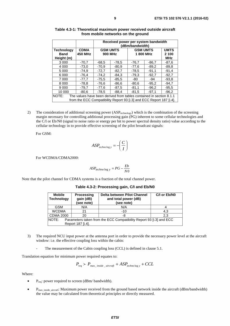
Table 4.3-1: Theoretical maximum power received outside aircraft from mobile networks on the ground
Received power per system bandwidth (dBm/bandwidth)
NOTE: The values have been derived from tables contained in section 8.1.1 from the ECC Compatibility Report 93 [i.3] and ECC Report 187 [i.4].
2) The consideration of additional screening power (ASPtechnology) which is the combination of the screening margin necessary for controlling additional processing gain (PG) inherent to some cellular technologies and the C/I or Eb/N0 (signal to noise ratio or energy per bit to power spectral density ratio) value according to the cellular technology in to provide effective screening of the pilot broadcast signals:
For GSM:
⎟⎠
⎞⎜⎝
⎛−=I
CASP ytechno log
For WCDMA/CDMA2000:
0log N
EbPGASP ytechno −=
Note that the pilot channel for CDMA systems is a fraction of the total channel power.
Table 4.3-2: Processing gain, C/I and Eb/N0
Mobile Technology
Processing gain (dB) (see note)
Delta between Pilot Channel and total power (dB)
(see note)
C/I or Eb/N0
GSM N/A N/A 4 WCDMA 21 -10 4,3
CDMA 2000 20 -8 2,3 NOTE: Parameters taken from the ECC Compatibility Report 93 [i.3] and ECC
Report 187 [i.4].
3) The required NCU input power at the antenna port in order to provide the necessary power level at the aircraft window: i.e. the effective coupling loss within the cabin:
- The measurement of the Cabin coupling loss (CCL) is defined in clause 5.1.
Translation equation for minimum power required equates to:
CCLASPPP ytechnoaircraftinsidereq ++ log__maxf
Where:
• Preq: power required to screen (dBm/ bandwidth).
• Pmax_inside_aircraft: Maximum power received from the ground based network inside the aircraft (dBm/bandwidth) the value may be calculated from theoretical principles or directly measured.
ETSI
ETSI TS 102 576 V2.1.1 (2016-02)10
• ASPtechnology: additional screening power (dB).
• CCL: cabin coupling loss (dB).
4.4 Derivation of the permitted maximum power level of the MCOBA system at the antenna input (Criterion B)
The maximum permitted power level will depend on the attenuation due to the aircraft fuselage in combination of the dedicated antenna.
Translation equation for GSMOBA system power equates to:
• E.I.R.P.outside: E.I.R.P. defined outside the aircraft (dBm/bandwidth) and values contained in clause 4.2.
• Pin: MCOBA system power level at the dedicated antenna output port (dBm/bandwidth).
• AttaircraftcabinfMHz antenna: effective attenuation (dB) to MCOBA system due to the aircraft and the dedicated antenna function of the frequency. The measurement of this parameter is defined in clause 5.3.
4.5 Derivation of the effective power level due to the UE onboard aircraft (Criterion C)
The effective power level outside the aircraft due to the onboard UE will depend on the effective aircraft attenuation at the window.
Translation equation for equivalent power outside the aircraft:
MHzfndowaircraftWimobout Aprieprie __........ −=
Where:
• E.I.R.P.out: E.I.R.P. defined outside the aircraft (dBm/200 kHz)
• E.I.R.P.mob: onboard mobile E.I.R.P. (0 dBm/200 kHz)
• AAircraftWindow_f_MHz: aircraft attenuation (dB) at the window at the desired frequency band
5 Description of test methodology to derive key parameters
5.1 Cabin coupling loss
5.1.1 General description of test set up
Location of the aircraft:
The aircraft should be located in a clear outdoor environment in order to keep the probability of possible corruption of measurement results due to signal reflections at obstacles outside the aircraft as low as possible.
Measurement locations inside the aircraft:
In principle it is not possible to specify generally accepted measurement locations within the aircraft because of the large variability in the aircraft cabin layout of different aircrafts. Therefore, the following rules shall provide guidance for specifying measurement locations for radio coverage testing:
• Coverage shall be tested at least in the forward, mid and aft fuselage section of the aircraft cabin to capture the longitudinal loss of the antenna system.
ETSI
ETSI TS 102 576 V2.1.1 (2016-02)11
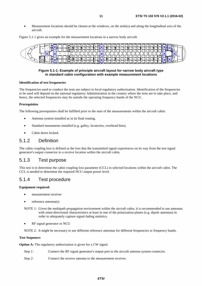
• Measurement locations should be chosen at the windows, on the aisle(s) and along the longitudinal axis of the aircraft.
Figure 5.1-1 gives an example for the measurement locations in a narrow body aircraft.
Figure 5.1-1: Example of principle aircraft layout for narrow body aircraft type in standard cabin configuration with example measurement locations
Identification of test frequencies
The frequencies used to conduct the tests are subject to local regulatory authorization. Identification of the frequencies to be used will depend on the national regulatory Administration in the country where the tests are to take place, and hence, the selected frequencies may be outside the operating frequency bands of the NCU.
Prerequisites
The following prerequisites shall be fulfilled prior to the start of the measurements within the aircraft cabin:
• Antenna system installed as in its final routing.
• Standard monuments installed (e.g. galley, lavatories, overhead bins).
• Cabin doors locked.
5.1.2 Definition
The cabin coupling loss is defined as the loss that the transmitted signal experiences on its way from the test signal generator's output connector to a receive location within the aircraft cabin.
5.1.3 Test purpose
This test is to determine the cabin coupling loss parameter (CCL) in selected locations within the aircraft cabin. The CCL is needed to determine the required NCU output power level.
5.1.4 Test procedure
Equipment required:
• measurement receiver
• reference antenna(s)
NOTE 1: Given the multipath propagation environment within the aircraft cabin, it is recommended to use antennas with omni-directional characteristics at least in one of the polarization planes (e.g. dipole antennas) in order to adequately capture signal-fading statistics.
• RF signal generator or NCU
NOTE 2: It might be necessary to use different reference antennas for different frequencies or frequency bands.
Test Sequence:
Option A: The regulatory authorization is given for a CW signal.
Step 1: Connect the RF signal generator's output port to the aircraft antenna system connector.
Step 2: Connect the receive antenna to the measurement receiver.
xx
xxx
xxx
x
x
xxx
ETSI
ETSI TS 102 576 V2.1.1 (2016-02)12
Step 3: Set the resolution bandwidth of the measurement receiver to 10 kHz; set the video bandwidth to approximately ten times the value of the resolution bandwidth.
Step 4: Activate the "RMS" detector of the measurement receiver.
Step 5: Select an authorized frequency.
Step 6: Set the centre frequency of the measurement receiver to the selected frequency. Set the frequency span of the measurement receiver such that the entire spectrum of the test signal is taken into account for power measurement.
Step 7: Set the RF signal generator accordingly.
Step 8: Activate transmission of the RF signal generator for the selected frequency at the authorized power level.
Step 9: Measure the received power at all locations inside the aircraft cabin as specified in clause 5.1.1 by using the reference antenna. While measuring, randomly vary the measurement location in the order of λc/2, where λc is the wavelength of the selected frequency. Further, while measuring randomly vary the polarization of the receive antenna by changing the antenna orientation relative to the leaky cable orientation.
Step 10: Calculate the overall average value of the received power per location defined as:
∑=
=N
irecmeanrec NiPP
1
/)(
Where:
- Prec(i) being the power received for the measurement i.
- N being the number of measurement.
Step 11: Calculate the standard deviation which is the spread of the data defined as:
1
))((( 2
1
−−
= ∑ =
N
PiPSD meanrec
N
i rec
Step 12: Determine the 95th percentile (CDF) receive power value per location
SDPP meanrecrec *645.1%95 −=
and Calculate the 95th percentile cabin coupling loss for each of the specified locations within the aircraft cabin according to the following equation:
- Ptransmit: total RF signal generator output power at frequency of interest.
- Preceive_95: total receive power at frequency of interest.
- Geff_reference_antenna: effective gain of reference antenna.
Determine the location with maximum 95th percentile cabin coupling loss and declare it as worst-case cabin coupling loss for that particular frequency.
Step 13: Repeat step 5 through 12 for all other frequencies.
ETSI
ETSI TS 102 576 V2.1.1 (2016-02)13
Option B: The regulatory authorization is given within the frequency bands operated by the NCU.
Step 1: Connect the NCU output port to the aircraft antenna system connector.
Step 2: Connect the receive antenna to the measurement receiver.
Step 3: Set the resolution bandwidth of the measurement receiver to 100 kHz; set the video bandwidth to approximately ten times the value of the resolution bandwidth.
Step 4: Activate the "RMS" detector of the measurement receiver.
Step 5: Select an authorized frequency band.
Step 6: Set the centre frequency of the measurement receiver to the selected frequency. Set the frequency span of the measurement receiver such that the entire spectrum of the test signal is taken into account for power measurement.
Step 7: Set the NCU accordingly.
Step 8: Activate transmission of the NCU for the selected frequency at the authorized power level.
Step 9: Follow the same process as defined in step 9 to step 12 in option A.
Step 10: Repeat step 5 through 9 for all other frequency bands.
5.2 Consideration for RF attenuation measurement on aircraft High level measurement description
Measurements are made within the aircraft cabin while the external signal, outside the aircraft, is placed on a platform which is moved around the aircraft in a circle as shown in figure 5.2-1.
NOTE 1: Alternatively the receiver can be placed outside the aircraft while the transmitter is inside the aircraft.
NOTE 2: If the antenna system installation within the aircraft is fully symmetrical then measurements using a semi-circle around the aircraft will be sufficient.
Location of the aircraft:
The aircraft should be located in a clear outdoor environment in order to keep the probability of possible corruption of measurement results due to signal reflections at obstacles outside the aircraft as low as possible.
Frequency authorization:
Due to the radiated measurement, an authorization has to be requested through the national regulatory administration of the country in which measurements are carried out. Moreover as the use of NCU frequency bands may be impossible, frequencies to be used for the tests should be close to those used by the MCOBA system.
Separation distance between the aircraft and the transmitter (radius of circle)
The choice of the separation distance between external transmitter and the centre of the aircraft is based on four constraints:
• that the 3 dB antenna beam width covers the entire aircraft cabin;
• that the separation distance from the transmitter to the centre of the aircraft is bigger than the wingspan and half of the overall aircraft length;
• that the Fresnel Zone at half distance between the transmitter and the receiver is not obstructed in order not to have additional absorption/ reflection on the ground. The following equation defining the radius of the Fresnel zone applies:
F
DR
*432.17=
ETSI
ETSI TS 102 576 V2.1.1 (2016-02)14
Where:
� F: is the frequency in MHz
� D: is the distance between the transmitter and the receiver in meter
� R: is the radius of the Fresnel zone at half distance in meter
Figure 5.2-1: Test location
The external antenna height is set to the same height as the aircraft windows. It is highlighted that by using the transmitter outside the aircraft with receiver located at the window and at the antenna system port then the procedures defined in clauses 5.3 and 5.4 can be combined.
5.3 Aircraft attenuation in combination with the aircraft antenna system
5.3.1 Test purpose
To define the attenuation of aircraft in combination with the aircraft antenna system for each operating frequency band covered by the NCU.
5.3.2 Methods of measurement
Equipment requirement
• RF signal generator
• Power amplifier
NOTE 1: A power amplifier might not be necessary in case the signal generator delivers enough signal power to ensure, that the receive signal falls into the dynamic range of the measurement receiver.
• Measurement receiver
• Reference antennas for transmission of the test signal
X metr
e
ETSI
ETSI TS 102 576 V2.1.1 (2016-02)15
• Antenna system installed as in its final routing
NOTE 2: It may be necessary to use different signal generators, power amplifiers and antennas for the different authorized frequency.
Test procedure:
Step 1: Set the transmit antenna and its mast, which is adjustable in height, on the platform outside the aircraft. Set the height of the transmit antenna mast according to the type of aircraft under investigation (i.e. mast at the same height than the aircraft windows).
Step 2: Connect the transmit antenna to the RF signal generator through a power amplifier.
Step 3: Within the aircraft cabin, connect the aircraft antenna system to the measurement receiver.
Step 4: Set the resolution bandwidth of the measurement receiver to 10 kHz; set the video bandwidth to approximately ten times the value of the resolution bandwidth.
Step 5: Activate the "RMS" detector, deactivate the average mode.
Step 6: Select one of the authorized frequency and set the RF signal generator accordingly.
Step 7: Activate transmission of the RF signal generator for the selected frequency at the authorized power level.
NOTE 3: The transmit signal power shall be high enough to be able to be measured by the receiver equipment. Depending on the authorization constraints, a pre-amplifier may be required to ensure that the signal is within the receiver's dynamic range.
Step 8: Set the centre frequency of the measurement receiver to the selected frequency. Set the frequency span of the measurement receiver such that the entire spectrum of the test signal is taken into account for power measurement (e.g. 100 kHz).
Step 9: Measure the receive power continuously and record the values while the transmit antenna on the movable platform is continuously moved slowly around the aircraft on the defined path.
Step 10: Repeat step 6 to 9 for the other authorized frequency bands.
5.3.3 Calculation of combined effective aircraft attenuation and antenna system
Step 1: For a selected frequency, calculate the aircraft attenuation in combination of the antenna system for each transmitter position by using the following formula:
- Gtransmitter being the transmitter antenna gain (dBi);
- FSL being the free space loss and defined as follows:
)log(20)log(204.27 mMHz dfFSL ++−= (dB)
- dm being the transmit-receive antenna separation in m; and
- fMHz being the frequency of the test signal in MHz.
ETSI
ETSI TS 102 576 V2.1.1 (2016-02)16
Step 2: In order to try to remove the effect of fading and to retain a sharp step, apply a moving average factor which is defined as followed:
[ ]jiAttM
iAttM
Jcableleakyaircraft →= ∑
−
=
1
0__
1)(
- M: number of point considered in the average.
- Attaircraft_leaky_cable: aircraft attenuation obtained at point i.
- Att(i): output value of the aircraft attenuation.
Step 3: Calculate the overall average value of the attenuation defined as:
∑=
=N
imean NiAttAtt
1
/)(
Where:
- Att(i) being the aircraft attenuation at point i.
- N being the number of point.
Step 4: Calculate the standard deviation which is the spread of the data defined as:
1
))((( 2
1
−−
= ∑ =
N
AttiAttSD mean
N
i
Step 5: Calculate the 5th percentile attenuation value of the CDF defined as:
SDAttAtt mean *645.1%5 −=
Step 6: Repeat Step 1 for the other frequencies.
5.4 Attenuation of aircraft at window
5.4.1 Test purpose
To define the attenuation of the aircraft at the window for each frequency band covered by the NCU.
5.4.2 Methods of measurement
Equipment requirement
• RF signal generator
• Power amplifier
• Measurement receiver
• Reference antennas for transmission and reception of the test signal
NOTE 1: It might be necessary to use different signal generators, power amplifiers and antennas for different frequency bands.
Test procedure:
Step 1: Set the transmit antenna and its mast on a platform, which is adjustable in height, outside the aircraft.
Step 2: Set the height of the transmit antenna mast at the same height than the aircraft windows.
ETSI
ETSI TS 102 576 V2.1.1 (2016-02)17
Step 3: Connect the RF signal generator to the transmit antenna through the power amplifier.
Step 4: Within the aircraft cabin, place the receive antenna close to an aircraft window, which is not shadowed by any part of the aircraft, i.e. a window having direct line-of-sight towards the transmit antenna outside the aircraft.
Step 5: Connect the receive antenna to the measurement receiver.
Step 6: Set the resolution bandwidth of the measurement receiver to 10 kHz; Set the video bandwidth to approximately ten times the value of the resolution bandwidth; Check the average mode is deactivated.
Step 7: Activate the "RMS" detector, deactivate the average mode.
Step 8: Select an authorized frequency and set the RF signal generator accordingly.
Step 9: Activate transmission of the RF signal generator for the selected frequency at the authorized power level.
NOTE 2: The transmit signal power shall be high enough to be able to be measured by the receiver equipment. Depending on the authorization constraints, a pre-amplifier may be required to ensure that the signal is within the receiver's dynamic range.
Step 9: Set the centre frequency of the measurement receiver to the selected frequency. Set the frequency span of the measurement receiver such that the entire spectrum of the test signal is taken into account for power measurement (e.g. 100 kHz).
Step 10: Measure the receive power continuously and record the values while the transmit antenna on the movable platform is continuously moved around the aircraft on the defined (semi) circle.
Step 11: Repeat step 7 to 10 for all the other test frequencies.
5.4.3 Calculation of aircraft attenuation at the window
Step 1: For a selected frequency, calculate the aircraft attenuation at the window for each position by using the following formula:
- Gtransmitter being the transmitter antenna gain (dBi).
- Greceiver being the receiver antenna gain (dBi).
- FSL being the free space loss (dB) and defined as follows:
)1log(20)log(204.27 mMHz dfFSL ++−= (dB)
where:
- fMHz being the frequency of the test signal in MHz; and
- d1m being the transmit-receive antenna separation in m which is defined as:
ETSI
ETSI TS 102 576 V2.1.1 (2016-02)18
Figure 5.4.3-1: Calculation of separation distance
22 )sin()cos(1 αα DDzD ++=
Where:
- D is the radius of the circle (m).
- z is the separation distance between the antenna located inside the cabin and the aircraft -centre (m).
- α is the angle defined by the position of the transmitter on the circle according to the reference (e.g.: aircraft nose is the reference and the transmitter runs clockwise).
Step 2: In order to try to remove the effect of fading and to retain a sharp step, apply a moving average factor which is defined as follows:
[ ]jiAttM
iAttM
Jwindowaircraft →= ∑
−
=
1
0_
1)(
- M: number of point considered in the average.
- Attaircraft_window: aircraft attenuation obtained at point i.
- Att(i): output value of the aircraft attenuation.
Step 3: Calculate the overall average value of the attenuation defined as:
∑=
=N
imean NiAttAtt
1
/)(
Where:
- Att(i) being the aircraft attenuation at point i.
- N being the number of point.
Step 4: Calculate the standard deviation, which is the spread of the data defined as:
1
))((( 2
1
−−
= ∑ =
N
AttiAttSD mean
N
i
D1 D
ETSI
ETSI TS 102 576 V2.1.1 (2016-02)19
Step 5: Calculate the 5th percentile attenuation value of the CDF defined as:
SDAttAtt mean *645.1%5 −=
Step 6: Repeat Step 1 for the other frequencies.
ETSI
ETSI TS 102 576 V2.1.1 (2016-02)20
Annex A (informative): System Description
A.1 High level System Description The MCOBA system comprises of an onboard BTS (OBTS) and a Network Control Unit (NCU). These are connected to a dedicated antenna system. The whole system is then connected to the ground network via a satellite link. Figure A.1-1 represents the high level system description.
GGW
2 3
4.
Public Land Network
1. Passenger handset 2. Airborne system
(MCOBA system)
3. Air - to - ground link 4. Ground station
1
MSC/SGSN
Figure A.1-1: Overview of the MCOBA system and associated terrestrial components
This description covers the onboard elements; OBTS, NCU and the antenna system.
Figure A.1-2 represents the functional organization of the MCOBA system. The dotted box identifies the equipment specified in ETSI EN 302 480 [i.5]. This system may comprise one or more NCUs, one or more BTS functions, antenna coupling units (ACU) and an antenna system.
3
1 NCU reference point 2 OBTS reference point 3 System reference point (NCU + OBTS)
System management
function
1
2
NCU Function
One or more OBTS function
ACU (Antenna coupler)
antenna system
Figure A.1-2: System description
ETSI
ETSI TS 102 576 V2.1.1 (2016-02)21
A.2 OBTS The OBTS establishes the communication access to the UE in the aircraft and supports all necessary system features such as radio access and radio resource management.
The OBTS has the following characteristics:
- support of GSM, UMTS and LTE services;
- GSM and LTE services operates in the 1 800 MHz spectrum band, UMTS services operates in the 2 100 MHz band;
- operates at a sufficient margin over the NCU level;
- ensures that an UE communicating with the OBTS transmits at the nominal minimum power level.
A.3 RF Screening Onboard aircraft mobile terminals should be prevented from attempting to access networks on the ground. This could be done:
- By passive means e.g. through RF shielding of the aircraft fuselage to further attenuate the signal entering and leaving the fuselage.
- By the inclusion of a Network Control Unit (NCU), which raises the noise floor inside the cabin in mobile receive bands by transmitting a broadband signal within those operating frequency bands.
These methods can be combined to minimize the active NCU power level.
The RF Screening covers the appropriate frequency ranges as identified in ETSI EN 302 480 [i.5].
NOTE: Any NCU will only be operational above the minimum height above the ground at which the system is permitted to be operated.
A.4 Antenna system Transmission of the signals is distributed in the cabin by an antenna system. This antenna system is specially designed for use onboard aircraft. The antenna system RF characteristics are defined by the following parameters:
- Number and type of transmit antennas in use.
- Method of transmission.
- Insertion loss.
- Coupling loss.
A.5 Antenna system installation Transmission of the signals distributed in the cabin may be affected by the type of installation used. The characteristics for the dedicated installation type are defined by the following parameters:
- Placement of the installation.
- Additional characteristics of installation.
ETSI
ETSI TS 102 576 V2.1.1 (2016-02)22
Annex B (informative): Bibliography
• ECC/DEC/(06)07: "ECC Decision of 1 December 2006 on the harmonised use of airborne GSM systems in the frequency bands 1710 -1785 and 1805 - 1880 MHz".
• ECC/DEC/2008/294/EC: "Commission Decision of 7 April 2008 on harmonised conditions of spectrum use for the operation of mobile communication services on aircraft (MCA services) in the Community".