ETSI TS 132 522 V10.2.0 (2011-06) Technical Specification Digital cellular telecommunications system (Phase 2+); Universal Mobile Telecommunications System (UMTS); LTE; Telecommunication management; Self-Organizing Networks (SON) Policy Network Resource Model (NRM) Integration Reference Point (IRP); Information Service (IS) (3GPP TS 32.522 version 10.2.0 Release 10)
Transcript
ETSI TS 132 522 V10.2.0 (2011-06)
Technical Specification
Digital cellular telecommunications system (Phase 2+);Universal Mobile Telecommunications System (UMTS);
LTE;Telecommunication management;
Self-Organizing Networks (SON) Policy Network Resource Model (NRM)
Integration Reference Point (IRP);Information Service (IS)
(3GPP TS 32.522 version 10.2.0 Release 10)
ETSI
ETSI TS 132 522 V10.2.0 (2011-06)13GPP TS 32.522 version 10.2.0 Release 10
Reference RTS/TSGS-0532522va20
Keywords GSM, LTE, UMTS
ETSI
650 Route des Lucioles F-06921 Sophia Antipolis Cedex - FRANCE
Tel.: +33 4 92 94 42 00 Fax: +33 4 93 65 47 16
Siret N° 348 623 562 00017 - NAF 742 C
Association à but non lucratif enregistrée à la Sous-Préfecture de Grasse (06) N° 7803/88
Important notice
Individual copies of the present document can be downloaded from: http://www.etsi.org
The present document may be made available in more than one electronic version or in print. In any case of existing or perceived difference in contents between such versions, the reference version is the Portable Document Format (PDF).
In case of dispute, the reference shall be the printing on ETSI printers of the PDF version kept on a specific network drive within ETSI Secretariat.
Users of the present document should be aware that the document may be subject to revision or change of status. Information on the current status of this and other ETSI documents is available at
http://portal.etsi.org/tb/status/status.asp
If you find errors in the present document, please send your comment to one of the following services: http://portal.etsi.org/chaircor/ETSI_support.asp
Copyright Notification
No part may be reproduced except as authorized by written permission. The copyright and the foregoing restriction extend to reproduction in all media.
DECTTM, PLUGTESTSTM, UMTSTM, TIPHONTM, the TIPHON logo and the ETSI logo are Trade Marks of ETSI registered for the benefit of its Members.
3GPPTM is a Trade Mark of ETSI registered for the benefit of its Members and of the 3GPP Organizational Partners. LTE™ is a Trade Mark of ETSI currently being registered
for the benefit of its Members and of the 3GPP Organizational Partners. GSM® and the GSM logo are Trade Marks registered and owned by the GSM Association.
ETSI TS 132 522 V10.2.0 (2011-06)23GPP TS 32.522 version 10.2.0 Release 10
Intellectual Property Rights IPRs essential or potentially essential to the present document may have been declared to ETSI. The information pertaining to these essential IPRs, if any, is publicly available for ETSI members and non-members, and can be found in ETSI SR 000 314: "Intellectual Property Rights (IPRs); Essential, or potentially Essential, IPRs notified to ETSI in respect of ETSI standards", which is available from the ETSI Secretariat. Latest updates are available on the ETSI Web server (http://webapp.etsi.org/IPR/home.asp).
Pursuant to the ETSI IPR Policy, no investigation, including IPR searches, has been carried out by ETSI. No guarantee can be given as to the existence of other IPRs not referenced in ETSI SR 000 314 (or the updates on the ETSI Web server) which are, or may be, or may become, essential to the present document.
Foreword This Technical Specification (TS) has been produced by ETSI 3rd Generation Partnership Project (3GPP).
The present document may refer to technical specifications or reports using their 3GPP identities, UMTS identities or GSM identities. These should be interpreted as being references to the corresponding ETSI deliverables.
The cross reference between GSM, UMTS, 3GPP and ETSI identities can be found under http://webapp.etsi.org/key/queryform.asp.
ETSI TS 132 522 V10.2.0 (2011-06)33GPP TS 32.522 version 10.2.0 Release 10
Contents
Intellectual Property Rights ................................................................................................................................ 2
4 SON Policy and Optimization Function Definitions ................................................................................ 8
4.1 Monitoring and Management Operations for Self-Optimization........................................................................ 8
4.1.1 Monitoring and Management Function......................................................................................................... 8
4.1.1.1 Usage of Itf-N ......................................................................................................................................... 8
4.2 Load Balancing Optimization Function ............................................................................................................. 8
4.2.1 Objective and Targets ................................................................................................................................... 8
4.2.2 Parameters To Be Optimized ........................................................................................................................ 9
4.2.3.1 Problem Detection ................................................................................................................................... 9
4.2.3.2 Problem Solution ..................................................................................................................................... 9
4.3 Handover (HO) Parameter Optimization Function ........................................................................................... 11
4.3.1 Objective and Targets ................................................................................................................................. 11
4.3.2 Parameters To Be Optimized ...................................................................................................................... 11
4.3.3.1 Problem Detection ................................................................................................................................. 12
4.3.3.2 Problem Solution ................................................................................................................................... 12
4.4 Interference Control Function .......................................................................................................................... 14
4.5 Capacity and Coverage Optimization Function ................................................................................................ 14
4.5.4.1 Definition of Logical Functions ............................................................................................................ 15
4.5.4.2 Location of Logical Functions .............................................................................................................. 15
4.6 RACH Optimization Function .......................................................................................................................... 16
4.6.1 Objective and Targets ................................................................................................................................. 16
4.6.2 Parameters to be optimized ......................................................................................................................... 17
4.6.3.1 Problem Detection ................................................................................................................................. 17
4.6.3.2 Problem Solution ................................................................................................................................... 17
ETSI TS 132 522 V10.2.0 (2011-06)43GPP TS 32.522 version 10.2.0 Release 10
5 Information Object Classes (IOCs) ........................................................................................................ 19
5.1 Information entities imported and local labels ................................................................................................. 19
5.2 Class diagram ................................................................................................................................................... 19
5.2.1 Attributes and relationships ........................................................................................................................ 19
5.3 Information Object Class (IOC) definitions ..................................................................................................... 22
5.6 Common Notifications ..................................................................................................................................... 31
Annex A (informative): Target Achievement Evaluation ................................................................... 32
Annex B (informative): Change history ............................................................................................... 33
History .............................................................................................................................................................. 34
ETSI
ETSI TS 132 522 V10.2.0 (2011-06)53GPP TS 32.522 version 10.2.0 Release 10
Foreword This Technical Specification has been produced by the 3rd Generation Partnership Project (3GPP).
The contents of the present document are subject to continuing work within the TSG and may change following formal TSG approval. Should the TSG modify the contents of the present document, it will be re-released by the TSG with an identifying change of release date and an increase in version number as follows:
Version x.y.z
where:
x the first digit:
1 presented to TSG for information;
2 presented to TSG for approval;
3 or greater indicates TSG approved document under change control.
y the second digit is incremented for all changes of substance, i.e. technical enhancements, corrections, updates, etc.
z the third digit is incremented when editorial only changes have been incorporated in the document.
Introduction The present document is part of a TS-family covering the 3rd Generation Partnership Project Technical Specification Group Services and System Aspects, Telecommunication management; as identified below:
32.521: Self-Organizing Networks (SON) Policy Network Resource Model (NRM) Integration Reference Point (IRP): Requirements
32.522: Self-Organizing Networks (SON) Policy Network Resource Model (NRM) Integration Reference Point (IRP): Information Service (IS)
32.526: Self-Organizing Networks (SON) Policy Network Resource Model (NRM) Integration Reference Point (IRP): Solution Set (SS) definitions
ETSI
ETSI TS 132 522 V10.2.0 (2011-06)63GPP TS 32.522 version 10.2.0 Release 10
1 Scope The present document is part of an Integration Reference Point (IRP) named Self Organizing Networks (SON) Policy Network Resource Model (NRM) IRP, through which an IRPAgent can communicate management information to one or several IRPManagers concerning SON policies. The SON policy NRM IRP comprises a set of specifications defining Requirements, a protocol neutral Information Service and one or more Solution Set(s).
The present document specifies the protocol neutral SON policy NRM IRP: Information Service (IS).
In order to access the information defined by this NRM, an Interface IRP such as the "Basic CM IRP" is needed (3GPP TS 32.602 [11]). However, which Interface IRP is applicable is outside the scope of the present document.
The present document also contains stage 2 descriptions for those functionalities for the Self-Optimization OAM.
2 References The following documents contain provisions which, through reference in this text, constitute provisions of the present document.
• References are either specific (identified by date of publication, edition number, version number, etc.) or non-specific.
• For a specific reference, subsequent revisions do not apply.
• For a non-specific reference, the latest version applies. In the case of a reference to a 3GPP document (including a GSM document), a non-specific reference implicitly refers to the latest version of that document in the same Release as the present document.
[1] 3GPP TS 32.101: "Telecommunication management; Principles and high level requirements".
[3] 3GPP TS 32.150: "Telecommunication management; Integration Reference Point (IRP) Concept and definitions".
[4] 3GPP TR 21.905: "Vocabulary for 3GPP Specifications".
[5] 3GPP TS 32.521: "Telecommunication management; Self-Organizing Networks (SON) Policy Network Resource Model (NRM) Integration Reference Point (IRP): Requirements".
[6] 3GPP TS 36.331: "Technical Specification Group Radio Access Network; Evolved Universal Terrestrial Radio Access (E-UTRA); Radio Resource Control (RRC); Protocol specification".
[7] 3GPP TS 36.423: "Technical Specification Group Radio Access Network; Evolved Universal Terrestrial Radio Access Network (E-UTRAN); X2 Application Protocol (X2AP)".
[8] 3GPP TS 32.425: "Technical Specification Group Services and System Aspects; Telecommunication management; Performance Management (PM); Performance measurements; Evolved Universal Terrestrial Radio Access Network (E-UTRAN)"
[9] 3GPP TS 32.622: "Telecommunication management; Configuration Management (CM); Generic network resources Integration Reference Point (IRP): Network Resource Model (NRM)"
[10] 3GPP TS 32.762: "Telecommunication management; Configuration Management (CM); Evolved Universal Terrestrial Radio Access Network (E-UTRAN) network resources Integration Reference Point (IRP): Network Resource Model (NRM)"
[11] 3GPP TS 32.602: "Telecommunication management; Configuration Management (CM); Basic CM Integration Reference Point (IRP) Information Service (IS)".
[12] 3GPP TS 36.413: "Technical Specification Group Radio Access Network; Evolved Universal Terrestrial Radio Access Network (E-UTRAN); S1 Application Protocol (S1AP)".
ETSI
ETSI TS 132 522 V10.2.0 (2011-06)73GPP TS 32.522 version 10.2.0 Release 10
[14] 3GPP TS 36.300: " Evolved Universal Terrestrial Radio Access (E-UTRA) and Evolved Universal Terrestrial Radio Access Network (E-UTRAN); Overall description; Stage 2 ".
[15] 3GPP TS 37.320: "Universal Terrestrial Radio Access (UTRA) and Evolved Universal Terrestrial Radio Access (E-UTRA); Radio measurement collection for Minimization of Drive Tests (MDT); Overall description; Stage 2".
3 Definitions and abbreviations
3.1 Definitions For the purposes of the present document, the terms and definitions given in TS 32.101 [1], TS 32.102 [2], TS 32.150 [3] and TR 21.905 [4] and the following apply. A term defined in the present document takes precedence over the definition of the same term, if any, in TS 32.521 [5], TS 32.101 [1], TS 32.102 [2] and TR 21.905 [4], in that order.
Target: See 3GPP TS 32.521 [5].
Trigger condition: See 3GPP TS 32.521 [5].
Hand-Over parameter Optimisation: See clause 4.3 of this document and Mobility Robustness Optimisation (MRO) are synonyms (see TS 36.300 [14]).
3.2 Abbreviations For the purposes of the present document, the abbreviations given in TR 21.905 [4], TS 32.521 [5] and the following apply. An abbreviation defined in the present document takes precedence over the definition of the same abbreviation, if any, in TR 21.905 [4] and TS 32.521 [5].
CAC Composite Available Capacity CDF Cumulative Distribution Function EM Element Manager eNodeB, eNB evolved NodeB E-UTRAN Evolved Universal Terrestrial Radio Access Network HO Handover HOO HandOver parameter Optimization ICIC Inter Cell Interference Coordination IOC Information Object Class LB Load Balancing LBO Load Balancing Optimization MRO Mobility Robustness Optimisation NM Network Manager NRM Network Resource Model OAM Operation Administration Maintenance RO RACH Optimization SON Self Organizing Networks UE User Equipment
ETSI
ETSI TS 132 522 V10.2.0 (2011-06)83GPP TS 32.522 version 10.2.0 Release 10
4 SON Policy and Optimization Function Definitions
4.1 Monitoring and Management Operations for Self-Optimization
4.1.1 Monitoring and Management Function
4.1.1.1 Usage of Itf-N
For specifically defined Itf-N NRM Interface see clause 5.
4.2 Load Balancing Optimization Function
4.2.1 Objective and Targets
The objective of LB Optimization is to cope with undesired traffic load distribution and to minimize the number of handovers and redirections needed to achieve the load balancing. One of the following targets or the combination of the following targets shall be used. The specific target value or values shall be configured by operators. Operators should assign weights for targets being used.
Targets drawn from the following table can be configured for LBO:
Target Name Definition Legal Values RRC connection establishments failure rate related to load
The number of Failed RRC connection establishments related to load/ The total number of Attempted RRC connection establishments. The target is met if the actual rate is smaller than the target value.
Integer [0..100] in unit percentage
E-RAB setup failure rate related to load
The number of E-RAB setup failure related to load/ The total number of attempted E-RAB setup For E-RAB setup failure related to load, the causes 'Reduce load in serving cell' and 'Radio resources not available' defined in TS 36.413 [12] could be used. The target is met if the actual rate is smaller than the target value.
Integer [0..100] in unit percentage
RRC Connection Abnormal Release Rate Related to Load
The number of abnormal RRC connection release related to load/ The total number of RRC connection release. The target is met if the actual rate is smaller than the target value.
Integer [0..100] in unit percentage
E-RAB Abnormal Release Rate Related to Load
The number of E-RAB abnormal release related to load/ The total number of E-RAB release For E-RAB setup failure related to load, the causes 'Reduce load in serving cell' and 'Radio resources not available' defined in TS 36.413 [12] could be used. The target is met if the actual rate is smaller than the target value.
Integer [0..100] in unit percentage
Rate of failures related to handover
(the number of failure events related to handover) / (the total number of handover events) The target is met if the actual rate is smaller than the target value.
Integer [0..100] in unit percentage
ETSI
ETSI TS 132 522 V10.2.0 (2011-06)93GPP TS 32.522 version 10.2.0 Release 10
For the following targets out of the above table, the target values depend on the composite available capacity range in the cell and are defined separately for uplink and downlink. For these tuples can be configured, indicating the capacity ranges together with the target value valid in that range.
RRC connection establishments failure rate related to load,
E-RAB setup failure rate related to load,
RRC Connection Abnormal Release Rate Related to Load,
E-RAB Abnormal Release Rate Related to Load
For the following targets shall be identical with the corresponding targets defined in Handover Optimization.
Rate of failures related to handover
4.2.2 Parameters To Be Optimized
To reach load optimization target, LBO may optimize some mobility settings (HO and/or idle mobility configuration) defined in TS 36.331 [6].
4.2.3 Optimization Method
4.2.3.1 Problem Detection
The problem detection is out of scope of this specification.
4.2.3.2 Problem Solution
The problem solution is out of scope of this specification.
4.2.4 Architecture
4.2.4.1 Definition of Logical Functions
LB Monitor Function: This function is used for monitoring the load balance optimization (e.g. Monitoring related performance counters or alarms).
LB Policy control function: This function is used for configuring the load balance optimization policies.
ETSI
ETSI TS 132 522 V10.2.0 (2011-06)103GPP TS 32.522 version 10.2.0 Release 10
4.2.4.2 Location of Logical Functions
For Load Balancing, the SON LB decision algorithm is located in eNB. The detailed SON functionalities in eNB are out of scope of this specification.
4.2.5 PM
IRPManager may collect Load balancing related performance measurements. Performance Measurements related with Load balancing are captured in the table below:
NM (IRPManager)
DM
eNB
Itf-N
eNB
EM
LB decision algorithm
LB decision algorithm
LB Monitor Function
LB Policy Control Function
X2 eNB
LB decision algorithm
LB Monitor Function
LB Policy Control Function
X2 EM
ETSI
ETSI TS 132 522 V10.2.0 (2011-06)113GPP TS 32.522 version 10.2.0 Release 10
Performance measurement name
Description Related targets
The number of Failed RRC connection establishments related to load
Refer to 3GPP TS 32.425 [8] Failed RRC connection establishments
RRC connection establishments failure rate related to load
The total number of Attempted RRC connection establishments
Refer to 3GPP TS 32.425 [8] Attempted RRC connection establishments
RRC connection establishments failure rate related to load
The number of E-RAB setup failure related to load
Refer to 3GPP TS 32.425 [8] Number of initial SAE Bearers failed to setup
E-RAB setup failure rate related to load
The total number of attempted E-RAB setup
Refer to 3GPP TS 32.425 [8] Number of initial SAE Bearers attempted to setup
E-RAB setup failure rate related to load
The number of abnormal RRC connection release related to load
Number of UE CONTEXT Release Request initiated by eNodeB
RRC Connection Abnormal Release Rate Related to Load
The total number of RRC connection release
Number of Successful UE Context Release
RRC Connection Abnormal Release Rate Related to Load
The number of E-RAB abnormal release related to load
Refer to 3GPP TS 32.425 [8] Number of SAE Bearers requested to release initiated by eNodeB per cause
E-RAB Abnormal Release Rate Related to Load
The total number of E-RAB release Refer to 3GPP TS 32.425 [8] Number of SAE Bearers successfully released
E-RAB Abnormal Release Rate Related to Load
the number of failure events related to handover
Refer to 4.3.5 Rate of failures related to handover
the total number of handover events
Refer to 4.3.5 Rate of failures related to handover
NOTE: The monitoring of performance measurements will make use of existing PM IRP.
4.3 Handover (HO) Parameter Optimization Function
4.3.1 Objective and Targets
For intra-LTE, one of the following targets or the combination of the following targets shall be used. The specific target value shall be configured by operators. Operators should assign weights for targets being used.
Target Name Definition Legal Values Rate of failures related to handover
(the number of failure events related to handover) / (the total number of handover events) The target is met if the actual rate is smaller than the target value.
Integer [0..100] in unit percentage
The objective of minimizing the number of unnecessary handovers shall always be pursued in case the other target/s configured by the operator is/are achieved. This objective may not need configuration of a target value.
4.3.2 Parameters To Be Optimized
The tables below summarise the handover parameters in TS 36.331 [6].
ETSI
ETSI TS 132 522 V10.2.0 (2011-06)123GPP TS 32.522 version 10.2.0 Release 10
Table 4.3.2-1. Handover parameters that may be optimized for intra-frequency and inter-frequency handovers
Event Summary Tunable parameters A3 Neighbour becomes offset better than serving Ofn, Ofs, Ocn, Ocs, Hys, Off, timeToTrigger A4 Neighbour becomes better than threshold Ofn, Ocn, Hys, Thresh, Off, timeToTrigger A5 Serving becomes worse than threshold1 and
Table 4.3.2-2. Handover parameters that may be optimised for inter RAT handover
Event Summary Tunable parameters B1 Inter RAT Neighbour becomes better than
threshold Ofn, Hys, Thresh, timeToTrigger
B2 Serving becomes worse than threshold1 and inter RAT neighbour becomes better than threshold2
Ofn, Hys, Thresh1, Thresh2, timeToTrigger
4.3.3 Optimization Method
4.3.3.1 Problem Detection
HO Parameter Optimization Function shall focus on detecting the problem scenarios described in TS 32.521 [5]; namely: too early handovers, too late handovers and inefficient use of NW resources due to HOs. For more information about these scenarios see TS 32.521 [5] section 6.1.3.
The following inputs may be used for the identification of the problem scenarios:
- Event capture and analysis
- UE measurements
- Performance measurements
In event capture and analysis, the eNodeB exploits event information associated with a UE context, such as evidence of previous handovers (UE History, see TS 36.423 [7]) and HO failure details (such as in which cell the handover failed and where the UE re-established the connection).
UE measurements are sent within UE measurement reports and they may indicate whether HOs are too early or too late.
HO-related performance measurements (PMs) collected at the source and / or target eNB can be useful in detecting HO-related issues on the cell level. Since the impact of incorrect HO parameter setting will also be on the cell-level, PMs can provide useful information that can be used to detect and resolve HO-related issues due to incorrect parameter settings.
4.3.3.2 Problem Solution
HO Parameter Optimization Function will aim at optimizing the HO parameters listed in Section 4.3.2 in such way to mitigate the problem scenarios discussed in Section 4.3.3.1. The optimization algorithms will not be specified. The exact set of HO parameters that may be adjusted by the algorithms is dictated by the choice of triggered HO measurements made by the RRM entity in an eNodeB.
4.3.4 Architecture
4.3.4.1 Definition of Logical Functions
HO Parameter Optimization Monitor Function: This function is used for monitoring the handover parameter optimization (e.g. monitoring related performance counters or alarms).
ETSI
ETSI TS 132 522 V10.2.0 (2011-06)133GPP TS 32.522 version 10.2.0 Release 10
HO Parameter Optimization Policy Control Function: This function is used for configuring the handover parameter optimization policies.
4.3.4.2 Location of Logical Functions
For HandOver (HO) parameter optimization there are several options for the location of the SON algorithm:
1. The SON algorithm is located in the eNB(s).
2. The SON algorithm is located in the EM, the parameter changes are executed in the eNBs.
An example for the first option is shown in figure 4.3.4.2:
Figure 4.3.4.2: Example when the SON algorithm is located in the eNB(s)
The detailed SON functionalities in eNB are out of scope of this specification.
4.3.5 PM
IRPManager shall collect HO-related performance measurements from the source and / or target eNB which can be useful in detecting HO-related issues on the cell level. The following input can be used for the identification of the problem scenarios specified:
The number of RLF event happened within an interval after handover success.
Performance Measurements related to handover failure are captured in the table below.
The Performance Measurements are for outgoing handovers. Further, they should be available on a cell relation basis.
NM
DM
eNB
Itf-N
EM
HO Parameter Optimization algorithm
HO Parameter Optimization Monitor Function
HO Parameter Optimization Policy Control Function
X2
HO Parameter Optimization Monitor Function
HO Parameter Optimization Policy Control Function
X2
eNB
HO Parameter Optimization algorithm
eNB
HO Parameter Optimization algorithm
EM
ETSI
ETSI TS 132 522 V10.2.0 (2011-06)143GPP TS 32.522 version 10.2.0 Release 10
Performance measurement name
Description Related targets
Number of handover events Includes successful handovers plus all identified failures
Rate of failures related to handover
Number of HO failures All failure cases Rate of failures related to handover
Number of too early HO failures Too early HO failure cases Rate of failures related to handover
Number of too late HO failures Too late HO failure cases Rate of failures related to handover
Number of HO failures to wrong cell
HO failures to wrong cell Rate of failures related to handover
NOTE: The monitoring of performance measurements will make use of existing PM IRP.
4.4 Interference Control Function
4.5 Capacity and Coverage Optimization Function
4.5.1 Objective and Targets
The objective of capacity and coverage optimization is to provide optimal coverage and capacity for the radio network. A tradeoff between capacity and coverage needs to be considered.
The detailed target(s) FFS.
4.5.2 Parameters to be optimized
To reach capacity and coverage optimization targets, the following parameters may be optimized:
• Downlink transmit power
• Antenna tilt
• Antenna azimuth
4.5.3 Optimization Method
4.5.3.1 Problem Detection
The main symptoms of capacity and coverage optimization problems (see TS 37.320 [15]) are:
Coverage hole: A coverage hole is an area where the pilot signal strength is below a threshold which is required by a UE to access the network, or the SINRs of both serving and neighbor cells is below a level needed to maintain the basic service. Coverage holes are usually caused by physical obstructions such as new buildings, hills, or by unsuitable antenna parameters, or just inadequate RF planning. UE in coverage hole will suffer from call drop and radio link failure. Typical phenomenon of coverage hole is either HO failure happens frequently and cannot be optimized by HO parameter optimization or call drop happens frequently and cannot be rescued by RRC re-establishment.
Weak coverage: Weak coverage occurs when the pilot signal strength or the SNR (or SINR) of serving cell is below the level needed to maintain a planned performance requirement (e.g. cell edge bit-rate).
Pilot pollution: In areas where coverage of different cells overlap a lot, interference levels are high, power levels are high, energy consumption is high and cell performance may be low. Typically in this situation UEs may experience high SNR to more than one cell and high interference levels.
Overshoot coverage: Overshoot occurs when coverage of a cell reaches far beyond what is planned. It can occur as an 'island' of coverage in the interior of another cell, which may not be a direct neighbor. Reasons for overshoot may be reflections in buildings or across open water, lakes etc. UEs in this area may suffer call drops or high interference.
ETSI
ETSI TS 132 522 V10.2.0 (2011-06)153GPP TS 32.522 version 10.2.0 Release 10
DL and UL channel coverage mismatch: DL channel coverage is larger than UL channel coverage is one typical scenario of DL and UL channel coverage mismatch. The UE will suffer UL problems when it moves into the mismatch area.
In a realistic network, these symptoms may be tolerated to a certain level. These symptoms may indicate a real problem when combined with other factors such as frequency of symptoms, duration of symptoms, or affected population.
The following inputs may be used for the identification of the problem scenarios:
• UE measurements
• Performance measurements
• Alarms, other monitoring information e.g. trace data
UE measurements are sent within UE measurement reports and they may indicate the capacity and coverage problem.
Capacity and coverage related performance measurements collected at the source and / or target eNB can be useful in detecting capacity and coverage related issues on the cell level. Minimizing Driver Test (MDT) or HO-related performance measurements may be used also in detecting capacity and coverage related issues on the cell level.
Alarms, other monitoring information e.g. trace data can be correlated to get an unambiguous indication of capacity and coverage problem.
4.5.3.2 Problem Solution
Capacity and coverage optimization function will aim at optimizing the parameters listed in Section 4.5.2 in such way to mitigate the problem scenarios discussed in Section 4.5.3.1.
4.5.4 Architecture
4.5.4.1 Definition of Logical Functions
CCO Monitor Function: This function is used for monitoring the capacity and coverage optimization (e.g. monitoring related performance counters, UE measurements or alarms).
CCO Policy Control Function: This function is used for configuring the capacity and coverage optimization policies.
4.5.4.2 Location of Logical Functions
For capacity and coverage optimization (CCO), there are several options for the location of the centralized CCO SON algorithm:
1. The CCO SON algorithm is located in the DM. The capacity and coverage optimization decision is made by the DM centralized CCO algorithm.
2. The CCO SON algorithm is located in the NM. The capacity and coverage optimization decision is made by the NM centralized CCO algorithm.
An example for the first option is shown in figure 4.5.4.2:
ETSI
ETSI TS 132 522 V10.2.0 (2011-06)163GPP TS 32.522 version 10.2.0 Release 10
Figure 4.5.4.2: Example when the CCO SON algorithm is located in DM
The detailed CCO SON algorithm in OAM (NM centralized or EM centralized) is out of scope of this specification.
4.5.5 PM
The IRPAgent shall support a capability allowing the IRPManager to collect CCO related performance measurements to know the situation of coverage or interference which may then trigger corresponding optimization procedures. Performance measurements related with CCO are captured in the table below:
Performance measurement name
Description Comment
Maximum carrier transmit power Refer to 3GPP TS 32.425 [8] Maximum value of the total carrier power transmitted in a cell.
Mean carrier transmit power Refer to 3GPP TS 32.425 [8] Mean value of the total carrier power transmitted in a cell.
4.6 RACH Optimization Function
4.6.1 Objective and Targets
The objective of RACH Optimization is to automatically set several parameters related to the performance of RACH. One of the following targets shall be used. The specific target value shall be configured by operators.
DM
NM
eNB
Itf-N
EM
CCO Monitor Function
CCO Policy Control Function
X2
CCO Monitor Function
CCO Policy Control Function
X2 eNB eNB EM
CCO Algorithm
ETSI
ETSI TS 132 522 V10.2.0 (2011-06)173GPP TS 32.522 version 10.2.0 Release 10
Target Name Definition Legal Values Access Probability, AP
The probability that the UE has access after a certain random access attempt number. The target is met if the actual access probability is higher than the target probability value.
CDF of access attempts. See section 5.5.1
Access Delay Probability, ADP
The probability distribution of Access Delay expected to be experienced by UEs accessing the RACH Channel. The target is met if the actual access probability is higher than the target probability value.
CDF of delays. See section 5.5.1
4.6.2 Parameters to be optimized
To achieve RACH optimization target, RACH optimization function may optimize several parameters defined in TS 36.300 [14] section 22.4.3.
4.6.3 Optimization Method
4.6.3.1 Problem Detection
The problem detection is out of scope of this specification since the RACH optimization entity resides in the eNB.
4.6.3.2 Problem Solution
The problem solution is out of scope of this specification since the RACH optimization entity resides in the eNB.
4.6.4 PM
The IRPAgent shall support a capability allowing the IRPManager to collect RACH optimization related performance measurements. Performance measurements related with RACH optimization are captured in the table below:
Performance measurement name
Description Related targets
Distribution of RACH preambles sent
Refer to 3GPP TS 32.425 [8] Cumulative Distribution of RACH preambles sent by UE
Access Probability, AP
Distribution of RACH access delay Refer to 3GPP TS 32.425 [8] Cumulative Distribution of RACH Access Delay
Access Delay Probability, ADP
4.7 Optimization coordination
4.7.1 Introduction
For coordination of SON Functions whose outputs are not standardized, the context of optimization coordination is:
1. IRPManager uses standardized capabilities to set the SON Function(s) targets, and where needed their weights.
Operators should assign weights for targets being used. The weights are used also for the evaluation of the targets. For details see Annex A.
For coordination of SON Functions whose outputs are standardized, the context of optimization coordination is FFS.
ETSI
ETSI TS 132 522 V10.2.0 (2011-06)183GPP TS 32.522 version 10.2.0 Release 10
4.7.2 Coordination between SON functions below Itf-N and CM operations over itf-N
FFS
4.7.3 Coordination between different SON functions
Note: The coordination between different SON functions should be decided case by case.
4.7.3.1 Coordination between Cell Outage Compensation and Energy Saving Management
4.7.3.1.1 Description
A conflict could arise between energy saving and cell outage compensation in the following scenario.
One or more candidate cells are configured to possibly take coverage of the original cell. The original cell is in energySaving state or is about to enter energySaving state. One or more candidate cells go into outage with the consequence that coverage of the original cell can not be provided any more.
4.7.3.1.2 Prevention
Prevention is hardly possible, except making the cells as outage proof as possible. But cell outages can happen even to the most stable cell in a network.
4.7.3.1.3 Resolution
If the original cell is in energySaving state, it shall leave energySaving state.
If the original cell is about to enter energySaving state, it shall not go into energySaving state until candidate cell outage is recovered and candidate cell is able to provide the coverage.
The original cell may go into the energySaving state after the candidate cell outage is recovered and coverage of the original cell can be taken over by candidate cell again.
ETSI
ETSI TS 132 522 V10.2.0 (2011-06)193GPP TS 32.522 version 10.2.0 Release 10
5 Information Object Classes (IOCs)
5.1 Information entities imported and local labels Label reference Local label
NOTE 1: IOC SONControl shall be instantiated whenever one or more IOC SONTargets are instantiated.
Figure 5.2.1-1: Cell view of SON Policy NRM
ETSI
ETSI TS 132 522 V10.2.0 (2011-06)203GPP TS 32.522 version 10.2.0 Release 10
ManagedElement(f rom TS 32.622)
<<InformationObjectCla...>>
Subnetwork(f rom TS 32.622)
<<InformationObjectCla...>>
11
<<names>>
0..*
1
ESPolicies<<InformationObjectCla...>>
0..11
ENBFunction(f rom TS 32.762)
<<InformationObjectCla...>>
0..*
1
ESPolicies<<InformationObjectClass>>
0..11
ESPolicies<<InformationObjectClass>>
<<names>>
0..*
1
<<names>>
1 0..1
1
<<names>>
0..*
1
<<names>>
0..1
EUtranGenericCell(f rom TS 32.762)
<<InformationObjectCla...>>
0..*
1
0..*
1<<names>>
0..11 0..11
<<names>>
Figure 5.2.1-2: ES Policies NRM IOCs (Containment Relationship)
NOTE 2: Also IOC SONControl is used for ES purposes – see clause 5.3.2.2 – but is not shown in Figure 5.2.1-2 to avoid the impression that there would an additional instance of this IOC be needed for ES.
EUtranCellSON<<InformationObjectClass>>
EUtranGenericCell(f rom TS 32.762)
<<InformationObjectClass>>
0..1
1
0..1
1
EUtranRelationSON<<InformationObjectClass>>
EUtranRelation(f rom TS 32.762)
<<InformationObjectClass>>
0..1
1
0..1
1
Figure 5.2.1-3: IOCs to control SON on cell or E-UTRAN relation level (Containment Relationship)
ETSI
ETSI TS 132 522 V10.2.0 (2011-06)213GPP TS 32.522 version 10.2.0 Release 10
5.2.2 Inheritance
SONTargets<<InformationObjectClass>>
SONControl<<InformationObjectClass>>
Top(from TS 32.622)
<<InformationObjectClass>>
Figure 5.2.2-1: SON Policy NRM Inheritance Hierarchy
Figure 5.2.2-2: ES Polices NRM IOCs (Inheritance Relationship)
EUtranRelationSON<<InformationObjectClass>>
Top(f rom TS 32.622)
<<InformationObjectClass>>
EUtranCellSON<<InformationObjectClass>>
Figure 5.2.2-3: Inheritance for IOC to control SON on cell or E-UTRAN relation level
ESPolicies(from TS 32.522)
<<InformationObjectClass>>
Top(from TS 32.622)
<<InformationObjectClass>>
ETSI
ETSI TS 132 522 V10.2.0 (2011-06)223GPP TS 32.522 version 10.2.0 Release 10
5.3 Information Object Class (IOC) definitions
5.3.1 SONTargets
5.3.1.1 Definition
This IOC represents targets for SON functions and their relative weights.
Target hierarchy rule:
An NRM IOC instance X may name-contain an IOC SONTargets instance T. The rule states that:
- If X name-contains a SONTargets instance T, then T is applicable to X.
- If X and all its superior instances do not name-contain any SONTargets instance, then no SONTargets instance is applicable to X.
- If X does not name-contain any SONTargets instance, but one or more of X"s superior instances name-contain a SONTargets instance, then the SONTargets instance of the superior instance closest to X, in X"s naming tree, is applicable to X.
5.3.1.2 Attributes
Attribute name Support Qualifier
Read Qualifier
Write Qualifier
hoFailureRate O *) M M rrcConnectionEstablishmentFailureRateCharacteristic O *) M M rrcConnectionAbnormalReleaseRateCharacteristic O *) M M eRabSetupFailureRateCharacteristic O *) M M eRabAbnormalReleaseRateCharacteristic O *) M M rachOptAccessProbability CM **) M M rachOptAccessDelayProbability CM **) M M *) Note 1: At least one of the attributes shall be supported.
**) Note 2: Only one of these attributes shall be present.
5.3.1.3 Attribute constraints
Name Definition rachOptAccessProbability CM Support Qualifier
RACH Optimization is supported and Access Probability is supported as target.
rachOptAccessDelayProbability CM Support Qualifier
RACH Optimization is supported and Access Delay Probability is supported as target.
5.3.1.4 Notifications
The common notifications defined in subclause 5.6.1 are valid for this IOC, without exceptions or additions.
5.3.2 SONControl
5.3.2.1 Definition
This IOC represents the possibility to switch on or off SON functions. This is provided for Handover optimization, Load Balancing optimization, Energy Saving and Cell Outage Compensation. For other SON functions like Coverage and Capacity optimization, RACH optimization etc. this is FFS.
ETSI
ETSI TS 132 522 V10.2.0 (2011-06)233GPP TS 32.522 version 10.2.0 Release 10
5.3.2.2 Attributes
Attribute name Support Qualifier Read Qualifier Write Qualifier hooSwitch CM M M lboSwitch CM M M esSwitch CM M M roSwitch CM M M cocSwitch CM M M
5.3.2.3 Attribute constraints
Name Definition hooSwitch CM Support Qualifier
Handover (HO) parameter Optimization function is supported.
lboSwitch CM Support Qualifier
Load Balancing Optimization function is supported.
esSwitch Support Qualifier
The condition is 'Distributed ESM architecture is supported'.
roSwitch CM Support Qualifier
RACH Optimization is supported.
cocSwitch Support Qualifier
The condition is 'CoC is supported'. Only allowed to be present, if SONControl is contained in subnetwork IOC instance.
5.3.2.4 Notifications
The common notifications defined in subclause 5.6.1 are valid for this IOC, without exceptions or additions.
5.3.3 ESPolicies
5.3.3.1 Definition
This IOC represents the energy saving policies information. This object class is valid in a distributed ES architecture or in an EM-centralized ES architecture.
5.3.3.2 Attributes
Attribute name Support Qualifier Read Qualifier Write Qualifier esActivationOriginalCellLoadParameters O M M esActivationCandidateCellsLoadParameters O M M esDeactivationCandidateCellsLoadParameters O M M
5.3.3.3 Attribute constraints
None.
5.3.3.4 Notifications
The common notifications defined in subclause 5.6.1 are valid for this IOC, without exceptions or additions
5.3.4 EUtranCellSON
5.3.4.1 Definition
This IOC represents the parameters for control of SON functions on E-UTRAN cell level.
ETSI
ETSI TS 132 522 V10.2.0 (2011-06)243GPP TS 32.522 version 10.2.0 Release 10
5.3.4.2 Attributes
Attribute name Support Qualifier
Read Qualifier
Write Qualifier
maximumDeviationHoTrigger CM M M minimumTimeBetweenHoTriggerChange CM M M
5.3.4.3 Attribute constraints
5.3.4.4 Notifications
The common notifications defined in subclause 5.6.1 are valid for this IOC, without exceptions or additions.
5.3.5 EUtranRelationSON
5.3.5.1 Definition
This IOC represents the parameters for control of SON functions on E-UtranRelation level.
5.3.5.2 Attributes
Attribute name Support Qualifier
Read Qualifier
Write Qualifier
cellIndividualOffsetDefault CM M M
5.3.5.3 Attribute constraints
5.3.5.4 Notifications
The common notifications defined in subclause 5.6.1 are valid for this IOC, without exceptions or additions.
5.4 Information relationship definitions None.
Name Definition maximumDeviationHoTrigger Support Qualifier
ETSI TS 132 522 V10.2.0 (2011-06)263GPP TS 32.522 version 10.2.0 Release 10
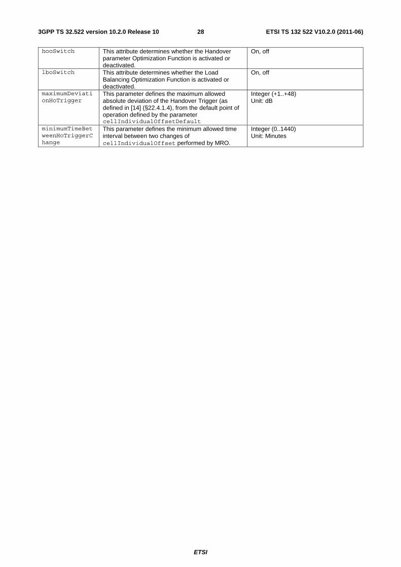
cocSwitch This attribute allows the operator to enable/disable the COC functionality.
Enumerated {on, off}
eRabAbnormalReleaseRateCharacteristic
The target is on the number of E-RAB abnormal release related to load divided by the total number of attempted E-RAB setups. This attribute allows to define for a value the composite available capacity (CAC) range in which the target is valid. For this, it contains one characteristic dependent on Uplink CAC, one for Downlink CAC: eRabAbnormalReleaseRateCharacteristicDownlink and eRabAbnormalReleaseRateCharacteristicUplink. At least one of these charateristics must be present. Together with the characteristic its targetWeight as a SON target is defined as part of this attribute. The characteristics have the following structure: eRabAbnormalReleaseRateCharacteristicDownlink: List of one or more entries, each consisting of: lowerEndOfCacRange, upperEndOfCacRange, eRabAbnormalReleaseRateTarget eRabAbnormalReleaseRateCharacteristicUplink: List of one or more entries, each consisting of: lowerEndOfCacRange, upperEndOfCacRange, eRabAbnormalReleaseRateTarget Remark: Formula for composite available capacity: Available Capacity = Cell Capacity Class Value * Capacity Value For definition of Cell Capacity Class Value and Capacity Value see TS 36.331 [6]. These definitions lead to a value range of a composite available capacity from 0..10000. 36.423 [7] has cell capacity class value as optional parameter in case of intra-LTE load balancing. If cell capacity class value is not present, than 36.423 assumes that bandwidth should be used instead to assess the capacity. This target is suitable for LBO.
lowerEndOfCacRange and upperEndOfCacRange: Integer 0..10000 eRabAbnormalReleaseRateTarget: Integer 0..100 (representing a percentage) targetWeight: Integer 1..N. The higher the number the higher the weight.
ETSI
ETSI TS 132 522 V10.2.0 (2011-06)273GPP TS 32.522 version 10.2.0 Release 10
eRabSetupFailureRateCharacteristic
The target is on the number of E-RAB setup failures related to load divided by the total number of attempted E-RAB setups. For E-RAB setup failure related to load the causes 'Reduce load in serving cell' and 'Radio resources not available' defined in TS 36.413 are used. This attribute allows to define for a value the composite available capacity (CAC) range in which the target is valid. For this, it contains one characteristic dependent on Uplink CAC, one for Downlink CAC: eRabSetupFailureRateCharacteristicDownlink and eRabSetupFailureRateCharacteristicUplink. At least one of these charateristics must be present. Together with the characteristic its targetWeight as a SON target is defined as part of this attribute. The characteristics have the following structure: eRabSetupFailureRateCharacteristicDownlink: List of one or more entries, each consisting of: LowerEndOfCacRange, UpperEndOfCacRange, eRabSetUpFailureRateTarget eRabSetupFailureRateCharacteristicUplink: List of one or more entries, each consisting of: LowerEndOfCacRange, UpperEndOfCacRange, eRabSetUpFailureRateTarget For CAC see eRabAbnormalReleaseRateCharacteristic This target is suitable for LBO.
lowerEndOfCacRange and upperEndOfCacRange and targetWeight: See eRabAbnormalReleaseRateCharacteristic eRabSetUpFailureRateTarget: Integer 0..100 (representing a percentage)
esActivationOriginalCellLoadParameters
This attribute indicates the traffic load threshold and the time duration, which are used by distributed ES algorithms to allow a cell to enter the energySaving state. The time duration indicates how long the load needs to have been below the threshold.
Threshold: Integer 0..100 (Percentage of PRB usage, see 3GPP TS 36.314 [13]) TimeDuration: Integer (in unit of seconds)
esActivationCandidateCellsLoadParameters
This attribute indicates the traffic load threshold and the time duration, which are used by distributed ES algorithms level to allow a cell to enter the energySaving state. Threshold and duration are applied to the candidate cell(s) which will provides coverage backup of an original cell when it is in the energySaving state. The time duration indicates how long the load needs to have been below the threshold.
Threshold: Integer 0..100 (Percentage of PRB usage (see 3GPP TS 36.314 [13]) TimeDuration: Integer (in unit of seconds)
esDeactivationCandidateCellsLoadParameters
This attribute indicates the traffic load threshold and the time duration which is used by distributed ES algorithms to allow a cell to leave the energySaving state. Threshold and time duration are applied to the cell(s) which provide coverage backup for the cell in energySaving state. The time duration indicates how long the load needs to have been above the threshold.
Threshold: Integer 0..100 (Percentage of PRB usage (see 3GPP TS 36.314 [13]) TimeDuration: Integer (in unit of seconds)
esSwitch This attribute determines whether the energy saving function is enabled or disabled.
On, off
hoFailureRate This indicates the assigned HOO target of the number of failure events related to handover divided by the total number of handover events, together with its targetWeight. This target is suitable for HOO or LBO.
A set of two numbers: the first indicates a percentage, the second a targetWeight (see eRabAbnormalReleaseRateCharacteristic).
ETSI
ETSI TS 132 522 V10.2.0 (2011-06)283GPP TS 32.522 version 10.2.0 Release 10
hooSwitch This attribute determines whether the Handover parameter Optimization Function is activated or deactivated.
On, off
lboSwitch This attribute determines whether the Load Balancing Optimization Function is activated or deactivated.
On, off
maximumDeviationHoTrigger
This parameter defines the maximum allowed absolute deviation of the Handover Trigger (as defined in [14] (§22.4.1.4), from the default point of operation defined by the parameter cellIndividualOffsetDefault
Integer (+1..+48) Unit: dB
minimumTimeBetweenHoTriggerChange
This parameter defines the minimum allowed time interval between two changes of cellIndividualOffset performed by MRO.
Integer (0..1440) Unit: Minutes
ETSI
ETSI TS 132 522 V10.2.0 (2011-06)293GPP TS 32.522 version 10.2.0 Release 10
rachOptAccessDelayProbability
This is a list of target Access Delay probability (ADP) for the RACH optimization function. Each instance ADP of the list is the target time before the UE gets access on the random access channel, for the P percent of the successful RACH Access attempts with lowest access delay, over an unspecified sampling period. This target is suitable for RO.
Each element of the list, ADPn, is a pair (a, b) where a is the targetProbability (in %) and b is the access delay (in milliseconds). The legal values for a are 25, 50, 75, 90. The legal values for b are 10 to 560. If ADPx"s a is larger than that of ADPy, then ADPx"s b must be larger than that of ADPy. The number of elements specified is 4. The number of elements supported is vendor specific. The choice of supported values for a and b is vendor-specific.
rachOptAccessProbability
This is a list of target Access Probability (APn) for the RACH optimization function. Each instance APn of the list is the probability that the UE gets access on the random access channel within n number of attempts, over an unspecified sampling period. This target is suitable for RO.
Each element of the list, APn, is a pair (a, n) where a is the targetProbability (in %) and n is the access attempt number. The legal values for a are 25, 50, 75, 90. The legal values for n are 1 to 200. If APx"s a is larger than that of APy, then APx"s n must be larger than that of APy. The number of elements specified is 4. The number of elements supported is vendor specific. The choice of supported values for a and n is vendor-specific.
roSwitch This attribute determines whether the RACH Optimization function is activated or deactivated.
On, off
ETSI
ETSI TS 132 522 V10.2.0 (2011-06)303GPP TS 32.522 version 10.2.0 Release 10
rrcConnectionAbnormalReleaseRateCharacteristic
The target is on the number of abnormal RRC connection releases related to load divided by the total number of RRC connection releases. This attribute allows to define for a value the composite available capacity (CAC) range in which the target is valid. For this, it contains one characteristic dependent on Uplink CAC, one for Downlink CAC: rrcConnectionAbnormalReleaseRateCharacteristicDownlink and rrcConnectionAbnormalReleaseRateCharacteristicUplink. At least one of these charateristics must be present. Together with the characteristic its targetWeight as a SON target is defined as part of this attribute. The characteristics have the following structure: rrcConnectionAbnormalReleaseRateCharacteristicDownlink: List of one or more entries, each consisting of: lowerEndOfCacRange, upperEndOfCacRange, rrcConnectionAbnormalReleaseRateTarget rrcConnectionAbnormalReleaseCharacteristicUplink: List of one or more entries, each consisting of: lowerEndOfCacRange, upperEndOfCacRange, rrcConnectionAbnormalReleaseRateTarget For CAC see eRabAbnormalReleaseRateCharacteristic This target is suitable for LBO.
lowerEndOfCacRange and upperEndOfCacRange and targetWeight: See eRabAbnormalReleaseRateCharacteristic rrcConnectionAbnormalReleaseRateTarget: Integer 0..100 (representing a percentage)
The target is on the number of RRC connection establishment failures related to load divided by the total number of attempted RRC connection establishments. This attribute allows to define for a value the composite available capacity (CAC) range in which the target is valid. For this, it contains one characteristic dependent on Uplink CAC, one for Downlink CAC: rrcConnectionEstablishmentFailureRateCharacteristicDownlink and rrcConnectionEstablishmentFailureRateCharacteristicUplink. At least one of these charateristics must be present. Together with the characteristic its targetWeigth as a SON target is defined as part of this attribute. The characteristics have the following structure: rrcConnectionEstablishmentFailureRateCharacteristicDownlink: List of one or more entries, each consisting of: lowerEndOfCacRange, upperEndOfCacRange, rrcConnectionEstablishmentFailureRateTarget rrcConnectionEstablishmentFailureRateCharacteristicUplink: List of one or more entries, each consisting of: lowerEndOfCacRange, upperEndOfCacRange, rrcConnectionEstablishmentFailureRateTarget For CAC see eRabAbnormalReleaseRateCharacteristic This target is suitable for LBO.
lowerEndOfCacRange and upperEndOfCacRange and targetWeigth: See eRabAbnormalReleaseRateCharacteristic rrcConnectionEstablishmentFailureRateTarget: Integer 0..100 (representing a percentage)
ETSI
ETSI TS 132 522 V10.2.0 (2011-06)313GPP TS 32.522 version 10.2.0 Release 10
5.5.2 Constraints
None.
5.6 Common Notifications
5.6.1 Configuration notifications
Name Qualifier Notes notifyAttributeValueChange O notifyObjectCreation O notifyObjectDeletion O
ETSI
ETSI TS 132 522 V10.2.0 (2011-06)323GPP TS 32.522 version 10.2.0 Release 10
Annex A (informative): Target Achievement Evaluation
To evaluate the result of the optimization the target achievement needs to be evaluated. This can be done by calculating the Total Target Achievement as follows.
The Total Target Achievement is the sum of the products of the individual target achievement (difference between target and performance) and the individual targetWeights:
Total Target Achievement = Sum i=1..n [ ( minTarget i – performance i ) x weighti ] + Sum j=1..n [ performance j – maxTarget j ) x weight j ]
where minTarget is a target to be minimized and maxTarget is a target to be maximized.
For targets with a substructure (like *Characteristic, see §5.5.1) the above formula is applied to each individual substructure target.
The higher the Total Target Achievement, the better is the result of the optimization.
ETSI
ETSI TS 132 522 V10.2.0 (2011-06)333GPP TS 32.522 version 10.2.0 Release 10
Annex B (informative): Change history
Change history Date TSG # TSG Doc. CR Rev Subject/Comment Old New 2010-03 SA#47 SP-100053 -- -- Presentation to SA for Information and Approval -- 1.0.0 2010-03 -- -- -- -- Publication of SA approved version 1.0.0 9.0.0 2010-09 SA#49 SP-100491 001 -- Remove targets based on not supported by measurements 9.0.0 9.1.0 2010-12 SA#50 SP-100858 003 1 Correcting the support qualifiers of SONControl attributes 9.1.0 9.2.0 2010-12 SA#50 SP-100749 005 - Disambiguate and correct the description of SON Targets hierarchy 9.1.0 9.2.0 2010-12 SA#50 SP-100833 002 3 Allow EM centralized architecture for Hand-over parameter
optimization - Align with 32.500 9.2.0 10.0.0
2010-12 SA#50 SP-100866 004 3 Adding NRM for Energy Saving Management policies and ESM switch
9.2.0 10.0.0
2011-01 -- -- -- - Correction of misimplementation of CR in clause 5.3.2.3 and CR history correction.
10.0.0 10.0.1
2011-03 SA#51 SP-110098 10 2 Introducing RACH optimization management 10.0.1 10.1.0 2011-03 SA#51 SP-110098 11 - Rapporteur clean-up for editorial errors 10.0.1 10.1.0 2011-03 SA#51 SP-110100 13 3 Use ESPolicies also for EM centralized architecture 10.0.1 10.1.0 2011-03 SA#51 SP-110100 14 - Correct cardinality of ESPolicies 10.0.1 10.1.0 2011-03 SA#51
SP-110097 16 - Add a new attribute into SONControl object class to switch on/off Cell Outage Compensation - Align with 32.541
10.0.1 10.1.0
2011-06 SA#52 SP-110284 18 1 Finalization of Rel-10 SON functionalities 10.1.0 10.2.0 2011-06 SA#52 SP-110284 66 2 Add parameters to control Mobility Robustness Optimization 10.1.0 10.2.0
ETSI
ETSI TS 132 522 V10.2.0 (2011-06)343GPP TS 32.522 version 10.2.0 Release 10