PennDOT LTAP technical INFORMATION SHEET #136 SPRING/2009 400 North Street, 6th Floor Harrisburg, PA 17120 1-800-FOR-LTAP • FAX (717) 783-9152 www.ltap.state.pa.us An Introduction to Guiderail Warrants and Layout The proper use and installation of guiderail is a difficult decision for many municipalities. Before deciding whether or not to install guiderail, a municipality should consider the safety, risk management, cost, and maintenance implications. The purpose of this technical bulletin is to provide an overview of the current standards, guidelines, and procedures for assessing the need for guiderail installations. Guiderails should not be installed without proper studies and consideration. Although guiderails can be useful in certain applications, the guiderail itself is a roadside hazard that can be struck by vehicles. How should a municipality approach the decision to install guiderail. Deciding whether to shield a roadside hazard with guiderail can be difficult, but decision-making guidelines are available in Chapter 12 of PennDot’s Design Manual, Part 2 (Publication 13M) and AASHTO’s Roadside Design Guide. These resources contain criteria for installing guiderail and information concerning what length, type, and end treatment of guiderail to install. WARRANTS To help determine whether devices such as guiderail should be used, engineers use warrants to work through their decisions. Warrants are criteria for justifying a possible solution, rather than rules that demand a solution. Guiderail warrants are similar to traffic signal and stop sign warrants in their application. Warranted guiderail – or other roadside barrier – does not guarantee that guiderail is needed; it is only an indication that guiderail should be considered. Less Restrictive Measures Guiderail is a traffic barrier used to prevent vehicles that leave the traveled roadway from hitting an object. Because barriers are a potential source of crashes themselves, their use should be carefully considered and employed only if hitting the object would potentially result in a more severe crash than simply hitting the barrier itself. In many cases, other safety measures can be more cost-effective to install and maintain than guidrail. Signing, pavement markings, and speed reduction methods can be used to help keep vehicles on the road. So, before employing guiderail to protect motorists from a roadside hazard, determine if some of these other measures would be more appropriate. Next, consider whether the hazard itself can be addressed. Can you remove the hazard? Can you move it further from the roadway edge, possibly beyond the clear zone? Can the hazard be made safer to hit (e.g., breakaway)? If the object cannot be removed, relocated, or made safer to hit, then guiderail and /or delineation should be considered. Finally, in locations where guiderail is already in use, examine the roadway to determine if other site features can be adjusted so that the guiderail can be elimated. Perhaps the embankment slope can be flattened, a fixed object can be removed, or a drainage head wall eliminated. Remember, guiderail should only be used in situations where a vehicle striking an object or leaving the roadway would result in more severe consequences than if it were to simply strike the guiderail. It is always best to consider less restrictive measures before installing guiderail.
Transcript
PennDOT LTAP
technicalINFORMATIONSHEET #136S P R I N G / 2 0 0 9
400 North Street, 6th Floor Harrisburg, PA 171201-800-FOR-LTAP • FAx (717) 783-9152www.ltap.state.pa.us
An Introduction to Guiderail Warrants and LayoutThe proper use and installation of guiderail is a difficult decision for many municipalities. Before deciding whether or not to install guiderail, a municipality should consider the safety, risk management, cost, and maintenance implications. The purpose of this technical bulletin is to provide an overview of the current standards, guidelines, and procedures for assessing the need for guiderail installations.
Guiderails should not be installed without proper studies and consideration. Although guiderails can be useful in certain applications, the guiderail itself is a roadside hazard that can be struck by vehicles.
How should a municipality approach the decision to install guiderail. Deciding whether to shield a roadside hazard with guiderail can be difficult, but decision-making guidelines are available in Chapter 12 of PennDot’s Design Manual, Part 2 (Publication 13M) and AASHTO’s Roadside Design Guide. These resources contain criteria for installing guiderail and information concerning what length, type, and end treatment of guiderail to install.
WARRANTSTo help determine whether devices such as guiderail should be used, engineers use warrants to work through their decisions. Warrants are criteria for justifying a possible solution, rather than rules that demand a solution.
Guiderail warrants are similar to traffic signal and stop sign warrants in their application. Warranted guiderail – or other roadside barrier – does not guarantee that guiderail is needed; it is only an indication that guiderail should be considered.
Less Restrictive MeasuresGuiderail is a traffic barrier used to prevent vehicles that leave the traveled roadway from hitting an object. Because barriers are a potential source of crashes themselves, their use should be carefully considered and employed only if hitting the object would potentially result in a more severe crash than simply hitting the barrier itself. In many cases, other safety measures can be more cost-effective to install and maintain than guidrail. Signing, pavement markings, and speed reduction methods can be used to help keep vehicles on the road. So, before employing guiderail to protect motorists from a roadside hazard, determine if some of these other measures would be more appropriate.
Next, consider whether the hazard itself can be addressed. Can you remove the hazard? Can you move it further from the roadway edge, possibly beyond the clear zone? Can the hazard be made safer to hit (e.g., breakaway)? If the object cannot be removed, relocated, or made safer to hit, then guiderail and /or delineation should be considered.
Finally, in locations where guiderail is already in use, examine the roadway to determine if other site features can be adjusted so that the guiderail can be elimated. Perhaps the embankment slope can be flattened, a fixed object can be removed, or a drainage head wall eliminated.
Remember, guiderail should only be used in situations where a vehicle striking an object or leaving the roadway would result in more severe consequences than if it were to simply strike the guiderail. It is always best to consider less restrictive measures before installing guiderail.
TS_136.indd 1 6/26/09 11:40 AM
2
Clear Zone ConceptIf less restrictive measures are not feasible, the first step in
deciding whether a guiderail or roadside barrier is warranted is determining the clear zone of the road in question. The actual clear zone is the total roadside border area, starting at the edge of the traveled roadway (referred to as the “traveled way”); that is available for safe use by errant vehicles. In other words, it is the distance from the edge of the traveled way to the existing hazard. The desired clear zone (what you would like to have) is based on traffic volume, design speed, and embankment slope. Table 1 (PennDOT’s Design Manual, Part 2, Table 12.1) can be used to determine the desired clear zone. These values should be adjusted by the factors in Table 2 (PennDOT’s Design Manual, Part 2, Table 12.2) when applied to the outside of horizontal curves.
To determine the clear zone on the outside of the curve, use the formula CZ = L x KWhere: CZ = clear zone width on outside of curve L = clear zone width from Table 1 (below-top) K = curve correction factor from Table 2 (below-
bottom)If a roadside hazard is not within the desired clear zone, it can
probably be left at its current location. If it is in the desired clear zone, then guiderail could be considered.
Table 1
Table 2
TS_136.indd 2 6/26/09 11:40 AM
3
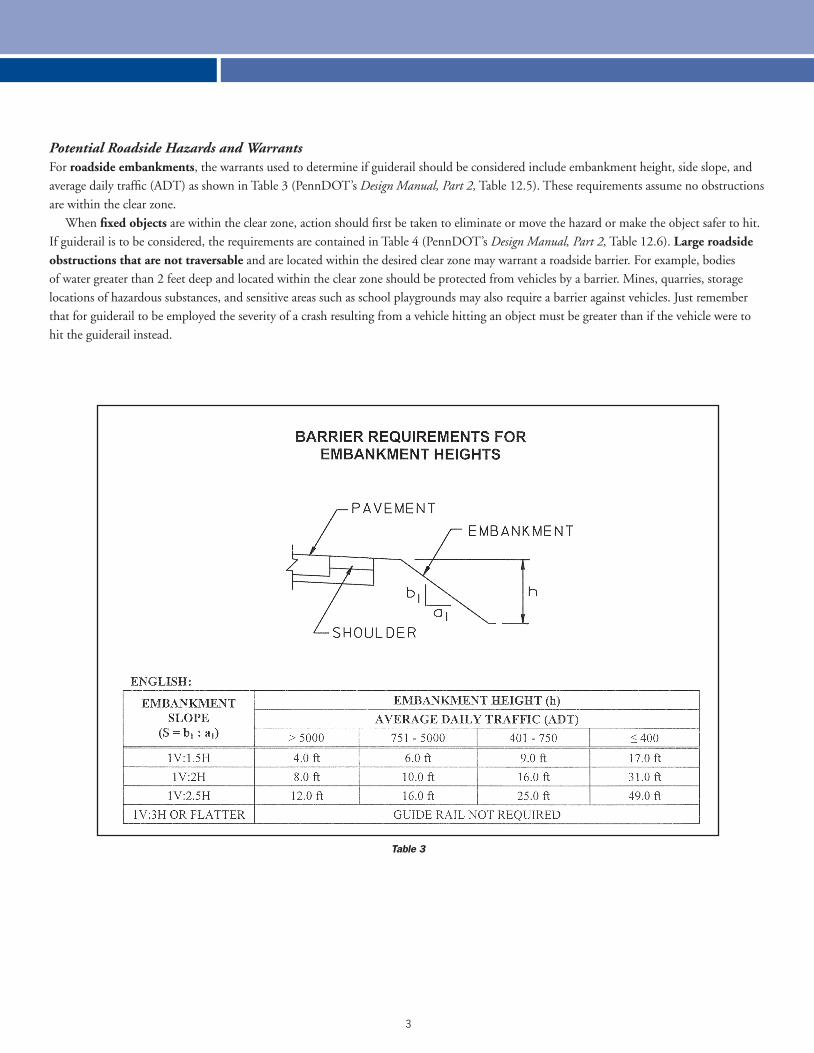
Potential Roadside Hazards and Warrants For roadside embankments, the warrants used to determine if guiderail should be considered include embankment height, side slope, and average daily traffic (ADT) as shown in Table 3 (PennDOT’s Design Manual, Part 2, Table 12.5). These requirements assume no obstructions are within the clear zone.
When fixed objects are within the clear zone, action should first be taken to eliminate or move the hazard or make the object safer to hit. If guiderail is to be considered, the requirements are contained in Table 4 (PennDOT’s Design Manual, Part 2, Table 12.6). Large roadside obstructions that are not traversable and are located within the desired clear zone may warrant a roadside barrier. For example, bodies of water greater than 2 feet deep and located within the clear zone should be protected from vehicles by a barrier. Mines, quarries, storage locations of hazardous substances, and sensitive areas such as school playgrounds may also require a barrier against vehicles. Just remember that for guiderail to be employed the severity of a crash resulting from a vehicle hitting an object must be greater than if the vehicle were to hit the guiderail instead.
Table 3
TS_136.indd 3 6/26/09 11:40 AM
4
Table 4
TYPESThe types of barrier systems are separated by their deflection
properties. The three types of systems are flexible, semi-rigid, and rigid systems. Generally, the guiderail system that provides the largest dynamic deflection should be used.
FlexibleThe flexible barrier system used in Pennsylvania is the W-beam
weak post guiderail. The W-beam weak post is characterized by smaller posts (3 inch) and no block-outs between the W-beam and the mounting posts. Since these barriers are the most forgiving, W-beam weak post systems require a minimum of 5 to 8 feet of unobstructed distance, which is the distance between the barrier face and the hazard. Although they require the largest unobstructed area due to their potential amount of deflection, flexible barriers do the best job of reducing vehicle impact forces. The cable guiderail, another flexible barrier system, is still found in Pennsylvania. This type of system generally consists of either wood or steel posts, three or four low-tension steel cables, and simple ground anchors. Although standard at one time, it is no longer appropriate to install this old style of guiderail in Pennsylvania.
Many vehicles struck and snagged the posts of this system. Because of this and the fact that cable guiderail tends to deteriorate over time, cable guiderail should be replaced, when the time comes, with the W-beam system.
Semi-rigid The semi-rigid system used in Pennsylvania is the W-beam
strong post system. This system can be identified by the wood or plastic block-out between the W-beam and the mounting posts, and by the larger posts (6 inch). Since the semi-rigid system deflects less than the flexible system, it exerts higher forces on an errant vehicle. The minimum unobstructed distance for the W-beam strong post system is 2 to 4 feet from the face of the W-beam to the hazard.
RigidThe most common rigid system is the concrete barrier,
sometimes referred to as the concrete F-shape barrier. This concrete barrier, which does not require an obstructed area, exerts tremendous force on a vehicle that hits it. It is used in situations where space is limited, such as in work zones.
TS_136.indd 4 6/26/09 11:40 AM
5
Choosing a Barrier TypeMany factors go into choosing the proper type of barrier. Be sure to work with a qualified engineer when designing a system. In general, W-beam weak post guiderail should be used whenever the minimum unobstructed distance is available. Some exceptions would be around large-radii curves, at intersections where impact angles can be greater than 25 degrees, at bridge approaches, and in curbed areas. In these cases and whenever the unobstructed distance is not available, the W-beam strong post system should be used.
LAYOUT
Lateral Location The lateral location, or offset from the traveled way, is important to assure that an errant vehicle will not vault the guiderail. The location should provide as much area as possible for an errant vehicle to recover before hitting the barrier. Therefore, guiderail should generally be placed as far from the traveled way as possible, and the recovery area should be kept free of obstructions. For example, the slope between the guiderail and traveled way should be 1:10 or less and not greater than 1:6. The guiderail should not be placed between 2 and 12 feet from the traveled way on a steep slope (see PennDOT’s Design Manual for details) because vehicles tend to vault the guiderail under these conditions. Vehicles may also vault guiderail that is not flush with the curb line. In a curbed section, the face of the rail element should be flush with or in front of the curb line. For guiderail systems to function as they should, they must be correctly installed. See the RC-50 series of standards in PennDOT’s Publication 72M, Standards for Roadway Construction, for installation details.
Length of NeedThe length of need refers to the length of barrier (not including the end treatment) placed in advance of a hazard to effectively shield the hazard from an errant vehicle. Without this protection, vehicles could easily travel behind the guiderail and strike the hazard anyway. The approximate length of need for a particular hazard can be determined in the field. The first step is to multiply the lateral extent of the hazard (D) by 15. The lateral extent of the hazard is the distance from the edge of the traveled way to the far side of the obstruction. If the obstruction is an embankment or if it extends beyond the clear zone, then the lateral extent is equal to the clear zone width.
From the upstream side of the hazard, walk along the edge of the traveled way a distance equal to 15 times D. From this spot, use paint or flags to establish a line to the lateral extent of the obstruction. To protect the obstruction, the barrier must intersect this line on two-lane, two-way roadways, this length should be determined for each side of the obstruction. On the far side of the roadway use the centerline as the edge of the traveled way.
Flaring Guiderail Guiderail is considered flared when it is not parallel to the ends of the traveled way. Guiderail may be flared to reduce the length of need or to bury it into a back slope. However, to keep impact angles with the guiderail as low as possible, maximum flare rates must be followed, as shown in Table 5 (PennDOT’s Design Manual, Part 2, Table 12.7).
Table 5
TS_136.indd 5 6/26/09 11:40 AM
6
If you have any questions, you can call LTAP at 1-800-FOR-LTAP for assistance.
END TREATMENTSGuiderail ends must be treated so a vehicle will not be impaled by an exposed rail element. On two-lane, two-way highways, both the approach and trailing ends of the guiderail should be treated. The preferred treatment is to bury the end of the guiderail
into a cut slope, retaining its full height even if the guiderail must be extended a short distance to accomplish this.
If a cut slope does not exist in the area, you must decide on the most appropriate end treatment. Guiderail end treatments fall into one of two categories: crashworthy or non-crashworthy. Crashworthy end treatments should not spear, vault, or roll a vehicle in a head-on or angled impact. If the guiderail ends within the clear zone and/or is in an area where it is likely to be hit by an errant vehicle on high-speed high-volume roadways, then a crashworthy end treatment should be used.
Crashworthiness of End Treatments Crashworthy end treatments can be gating or non-gating by design. A gating terminal allows a vehicle to pass through after impact and thus requires a run out area. A non-gating system will gradually stop or redirect a vehicle away from a fixed object. The following crashworthy end treatments and crash cushions are the most appropriate options to terminate guiderail on local roads in Pennsylvania:
• Anchored in backslope• FLEAT-350• SRT-350• ET-PLUS• SKT-350
The preferred treatment is to anchor the guiderail in the backslope. To do this, the guiderail should be flared in accordance with the rates in Table 5. If the guiderail cannot be buried, Chapter 12 of Design Manual, Part 2 should be consulted for detailed characteristics of other end treatments. These crashworthy end treatments are continually updated and redesigned to improve their safety characteristics. Refer to Chapter 12 of Design Manual, Part 2 for the latest information on their use and availability.
Non-Crashworthy Crashworthy end treatments are often not used on local roads
either because of low-traffic volumes and low-traffic speeds or because the guiderail terminates outside of the desired clear zone. In these cases, a non-crashworthy end treatment is frequently employed. The most common non-crashworthy end treatment is the turned-down, or “Texas twist.” These end treatments are not crashworthy because they tend to vault vehicles, especially those traveling at high rates of speed. Another commonly used non-crashworthy end treatment is the terminal end treatment, more commonly referred to as a “fist” or “boxing glove.”
Non-crashworthy end treatments are often seen at driveways and intersections and in locations where a radius can be used to terminate the guiderail outside of the desired clear zone. However, if the end treatment is in the clear zone, the average daily traffic is greater than 4,000 vehicles per day, or the speed limit of the roadway is greater than 45 mph, non-crashworthy end treatments are not compliant with current standards. Non-crashworthy end treatments are detailed in PennDOT’s Roadway Construction (RC) Standards, Publication 72M.
STEPS TO FOLLOWIn conclusion, the following steps should be followed before
installing guiderail:Step 1. Collect field data, including location of hazards, to determine
the actual and desired clear zones for the roadway area of concern. Step 2. Analyze traffic and field data (speeds, volumes, crash history) to
determine if less restrictive measures can be applied to the hazard. Step 3. Check to see if the barrier is warranted in the area of concern.Step 4. Choose the appropriate barrier type. Step 5. Determine the lateral offset of the barrier.Step 6. Determine the length of need and flare rate. Step 7. Choose the appropriate end treatment.
These steps should be followed while consulting PennDOT’s Design Manual, Part 2 Publication 72M. Remember that guiderail should only be used at locations where the result of a vehicle striking the object or leaving the roadway would be more severe than the consequence of it striking the guiderail.