92
TSE Administration Software

TSE Administration Software

BA TSE Administration Software 20130121_dp 1
Dear customer, Thank you very much for having chosen a lock administration software by BURG-WÄCHTER. It is available in 4 different versions, which are optimally adapted to different requirements:
TSE 5500 Software LIGHT TSE 6501 Software SYSTEM TSE 6502 Software SYSTEM + TSE 6000 HOTEL CODE (not further described in this guide)
The individual versions provide different functionalities, for example a different selection and number of opening media and a different number of users administering the system. According to the software version, administration of pin codes, active and passive transponders, as well as fingerprints is possible. A link between the USB adapter and the computer via the USB interface is necessary for data transmission. For data transmission, a maximum wireless distance of 20 m should not be exceeded. This value depends on the environment and thus can vary. All data transmissions are bidirectional, this means from the wireless key to the lock or computer, from the keypad to the lock and from the computer to the lock and vice versa. Communication of security-relevant data is AES-encrypted. Apart from this, the TSE 6501 SYSTEM and the TSE 6502 SYSTEM + software are network-enabled. Users are created and managed in an offline mode, permanent wireless communication between the cylinder and the software is therefore not necessary. Wireless data transmission to the lock or to the computer is based on 12 different RFID channels, providing smooth operation. When the software is being installed, a version check related to the USB adapter takes place. This identifies the acquired software version. After the programme has been started, the version is identified automatically. A common feature of all the software versions is that the software can also provide for administration of the TRSE 6000 and TRSE 6000 FS safe electronics (safe systems) manufactured by BURG-WÄCHTER. The particularities, which should be taken into account when administering the safe electronics, are described in a separate chapter. Please read also the User Manuals for TRSE 6000 and TRSE 6000 FS in this respect. This guide is structured in a way that the properties of the individual software types are described first, then the procedures applicable to all the types are explained.
BA TSE Administration Software 20130121_dp 2
Inhalt
1 INSTALLATION IN WINDOWS XP, WINDOWS VISTA AND WINDOWS 7 ..... 4
2 ADDITIONAL OPTIONS FOR WINDOWS 8 ................................................... 10
2.1 No existing driver .................................................................................................................................. 10
2.2 Wrong TSE driver ................................................................................................................................ 11
2.3 Manually driver update ........................................................................................................................ 11
2.4 Faulty connection between the TSE adapter and the computer ....................................................... 14
3 DEACTIVATING OF THE AUTOMATIC DRIVER INSTALLATION IN .................. WINDOWS 8 .................................................................................................. 15
4 CONVERTING A DATABASE ......................................................................... 17
4.1 Converting from an old database ........................................................................................................ 17
4.2 Loading an existing database ............................................................................................................... 20
5 DATA BACKUP AND UNINSTALLATION ....................................................... 23
6 SETTING THE CYLINDER TO THE GUEST CARD MODE ................................ 24
6.1 Changeover of TSE 6000 cylinder to the use of TSE 6000 HOTEL Code ....................................... 25
6.2 Conversion of TSE 6000 cylinder to the use of TSE 6000/ + hotel Guest Cards ............................ 27
6.3 Conversion of TSE 6000 CYLINDER to the use of TSE 6000 HOTEL CODE / ............................... + Guest Cards Hotel ............................................................................................................................ 28
6.4 Conversion of TSE 6000 CYLINDER to the use of TSE 6000/ + Guest Cards Facility ................. 29
7 SOFTWARE VERSIONS .................................................................................. 30
7.1 TSE 5500 Software LIGHT ................................................................................................................. 31
7.2 TSE 6501 Software SYSTEM .............................................................................................................. 32
7.3 TSE 6502 Software System + ............................................................................................................... 33 7.3.1 Creating / opening clients .............................................................................................................. 34 7.3.2 Creating new client........................................................................................................................ 34 7.3.3 Opening existing client .................................................................................................................. 35
8 SOFTWARE STRUCTURE ............................................................................... 36
BA TSE Administration Software 20130121_dp 3
8.1 Configuration ........................................................................................................................................ 37 8.1.1 Default Settings ............................................................................................................................. 37 8.1.2 Guest card settings ........................................................................................................................ 42 8.1.2.1 Hotel mode ............................................................................................................................... 44 8.1.2.2 Assignment of doors ................................................................................................................. 45 8.1.2.3 Card loss in hotel applications .................................................................................................. 46
8.2 Administration ...................................................................................................................................... 47 8.2.1 Users .............................................................................................................................................. 47 8.2.1.1 Timers ....................................................................................................................................... 49 8.2.1.2 Rights ....................................................................................................................................... 50 8.2.1.3 Key ID ...................................................................................................................................... 50 8.2.1.4 Storing E-KEY/SWITCH ......................................................................................................... 52 8.2.1.5 Storing transponder .................................................................................................................. 52 8.2.1.6 Searching for E-KEY/SWITCH ............................................................................................... 53 8.2.1.7 Searching for transponder ......................................................................................................... 53 8.2.1.8 Synchronise E-KEY/SWITCH ................................................................................................. 53 8.2.1.9 Fingerprint administration ........................................................................................................ 54 8.2.2 Lock assignment ............................................................................................................................ 57 8.2.3 Group assignment .......................................................................................................................... 58 8.2.4 Overview of group assignments .................................................................................................... 60
8.3 Lock administration ............................................................................................................................. 61 8.3.1 Locks ............................................................................................................................................. 61 8.3.2 Lock configuration ........................................................................................................................ 62 8.3.3 Groups ........................................................................................................................................... 70
8.4 Data transmission ................................................................................................................................. 71 8.4.1 Transmission of data ..................................................................................................................... 72
8.5 Guest card programming ..................................................................................................................... 75 8.5.1 Card loss ........................................................................................................................................ 76 8.5.2 History ........................................................................................................................................... 77
8.6 Time Management ................................................................................................................................ 78 8.6.1 User timer setup ............................................................................................................................ 79 8.6.2 User timer ...................................................................................................................................... 79 8.6.3 Permanent timer setup ................................................................................................................... 80 8.6.4 Permanent timer ............................................................................................................................ 81 8.6.5 TSE Control timer setup ................................................................................................................ 82 8.6.6 TSE Control timer ......................................................................................................................... 84
8.7 Calendar management ......................................................................................................................... 85 8.7.1 One-time holidays ......................................................................................................................... 85 8.7.2 Permanent holidays ....................................................................................................................... 86
9 PROGRAMMING OF SAFE ELECTRONICS ..................................................... 88
BA TSE Administration Software 20130121_dp 4
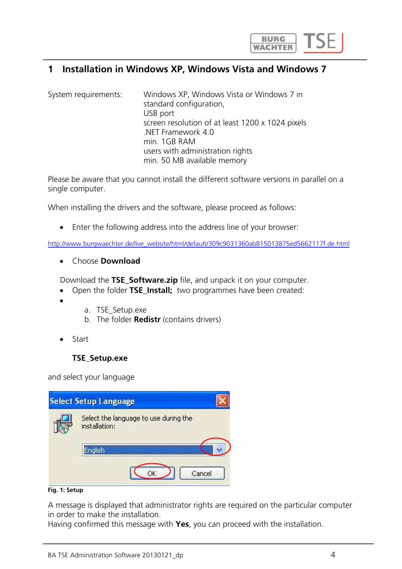
1 Installation in Windows XP, Windows Vista and Windows 7
System requirements: Windows XP, Windows Vista or Windows 7 in standard configuration, USB port screen resolution of at least 1200 x 1024 pixels .NET Framework 4.0 min. 1GB RAM users with administration rights min. 50 MB available memory Please be aware that you cannot install the different software versions in parallel on a single computer. When installing the drivers and the software, please proceed as follows:
Enter the following address into the address line of your browser: http://www.burgwaechter.de/live_website/html/default/309c9031360ab815013875ed5662117f.de.html
Choose Download
Download the TSE_Software.zip file, and unpack it on your computer. Open the folder TSE_Install; two programmes have been created:
a. TSE_Setup.exe b. The folder Redistr (contains drivers)
Start
TSE_Setup.exe
and select your language
Fig. 1: Setup
A message is displayed that administrator rights are required on the particular computer in order to make the installation. Having confirmed this message with Yes, you can proceed with the installation.

BA TSE Administration Software 20130121_dp 5
Fig. 2: Setup
Confirm the license agreement.
Fig. 3: Setup
The storage places differ depending on the operating system: Windows XP: C:\Programme\BURG-WACHTER\TSE Windows 7: C:\Program Files (x86)\BURG-WACHTER\TSE
Fig. 4: Setup Windows 7

BA TSE Administration Software 20130121_dp 6
Fig. 5: Setup
Here you decide whether just the currently logged in user may execute the programme or whether it will be available to all the users. Based on this, the storage path of the database is determined.
Fig. 6: Setup
Fig. 7: Setup
BA TSE Administration Software 20130121_dp 7
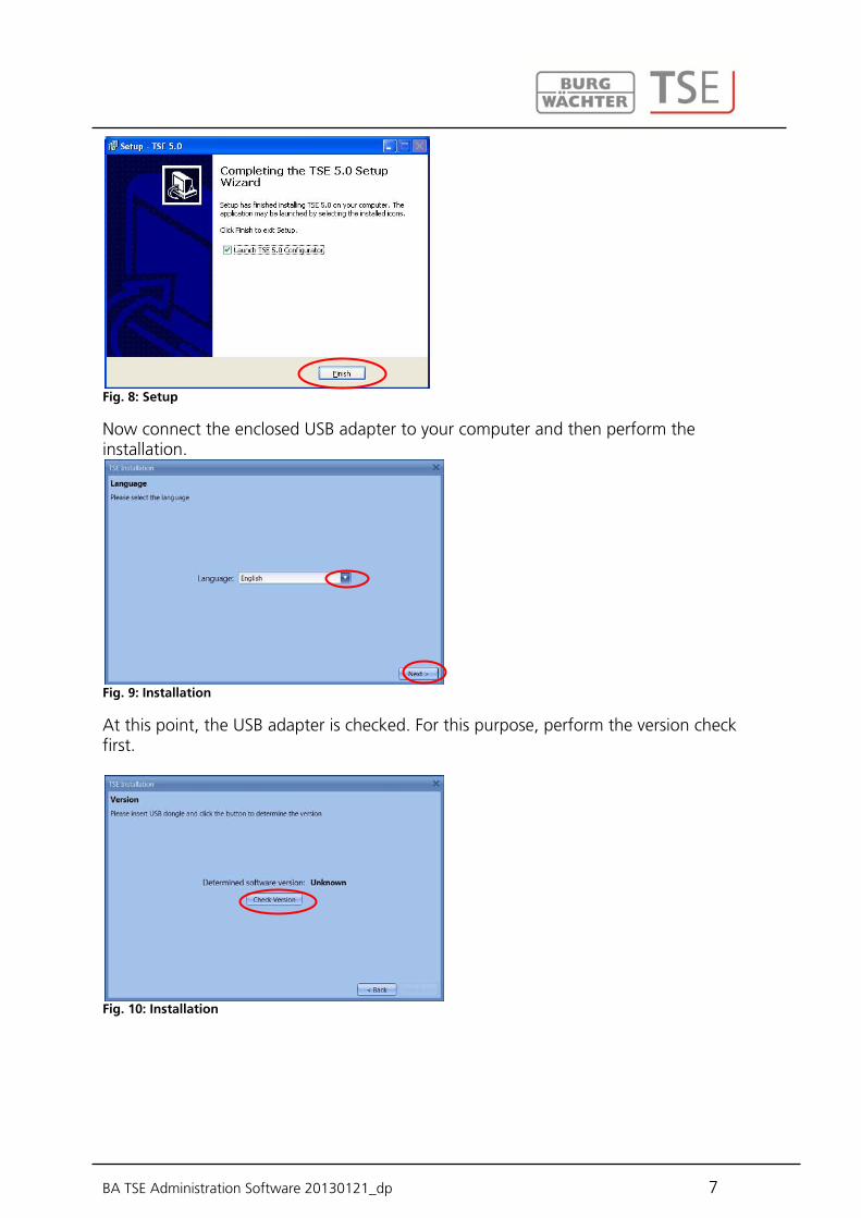
Fig. 8: Setup
Now connect the enclosed USB adapter to your computer and then perform the installation.
Fig. 9: Installation
At this point, the USB adapter is checked. For this purpose, perform the version check first.
Fig. 10: Installation

BA TSE Administration Software 20130121_dp 8
The name of the software version is displayed (in this particular case, the TSE 6502 SYSTEM + software is available).
Fig. 11: Installation
Now select the database type.
Fig. 12: Installation 6502 SYSTEM + Installation TSE 5500 LIGHT and TSE 6501 SYSTEM
Fig. 13: Installation
BA TSE Administration Software 20130121_dp 9
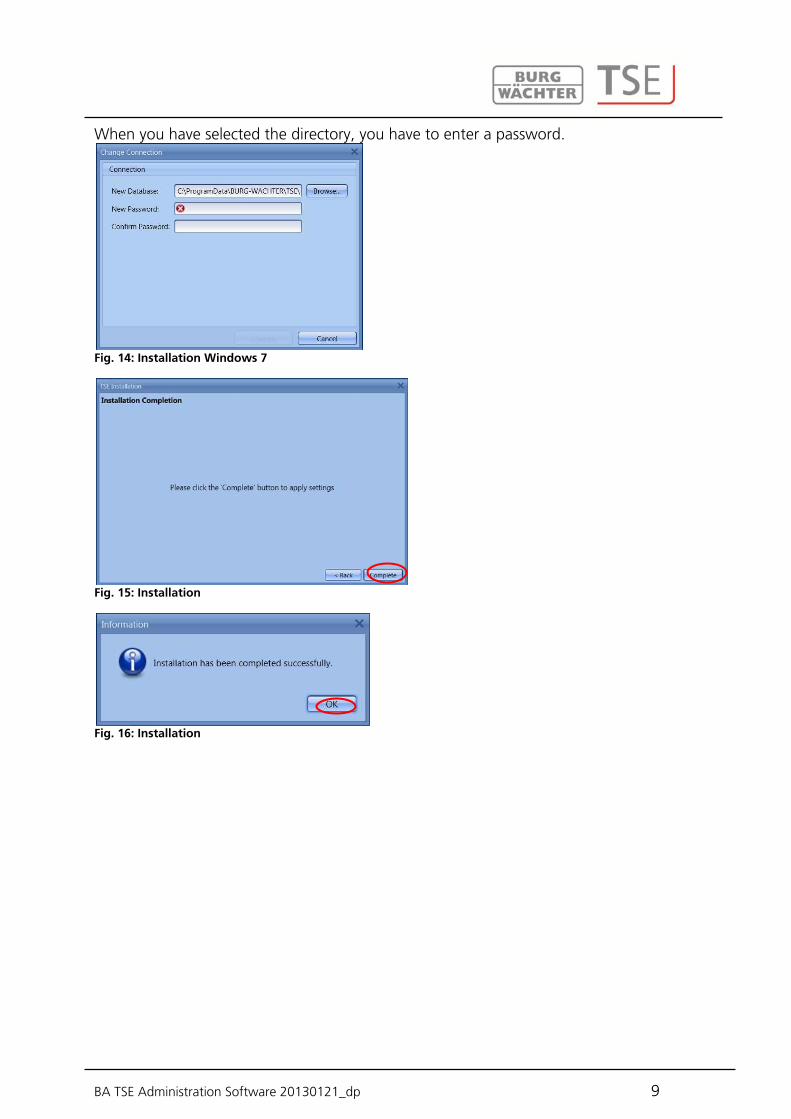
When you have selected the directory, you have to enter a password.
Fig. 14: Installation Windows 7
Fig. 15: Installation
Fig. 16: Installation

BA TSE Administration Software 20130121_dp 10
2 Additional options for Windows 8
Due to the fact of different drivers or none existing drivers Windows 8 systems have a special automatical check-up of its drivers. During the installation at the Version check or during an automatical update of the Windows software the DOS window displays. Attention: If the automatical driver update is activated on your computer existing drivers could be overwritten. In this case you will be requested to execute the following steps. Therefore we suggest to deactivate the automatical driver updating routine. (Please compare with the following chapter) Please make sure that you have administration rights to be authorised to fulfill the following steps. Different cases will be analysed.
there is no existing driver the wrong driver is existing the automatical driver update failed faulty connection between the TSE adapter and the computer
If there is no existing driver the driver has to be installed. The following information appears:
Abb. 17: Warning message DOS window
Press Enter to install the driver.
2.1 No existing driver

BA TSE Administration Software 20130121_dp 11
Abb. 18: Driver installation
Press Enter again to close the DOS window und restart the TSE software again.
If the wrong TSE driver is installed on the computer it will be updated automatically. Please follow the instructions in the DOS window and restart the TSE software.
If the automatical driver update failed you have to install manually. After detecting a wrong or non-existing drivers the system tries to update automatically.
Abb. 19: Status info
Press Enter and restart the TSE software. If the DOS window appears again during the version check the automatical driver update failed. The driver update has to be done manually.
2.2 Wrong TSE driver
2.3 Manually driver update

BA TSE Administration Software 20130121_dp 12
Please open the Start symbol first with the right mouse button. Then navigate to the Device Manager.
Abb. 20: Device Manager
Choose Update Driver Software
Abb. 21: Driver software update 1
Choose Browse my computer for driver software
Abb. 22: Driver software update 2
You will find the necessary drivers in the installation directory of the TSE software. Choose the drive in which the installation of the software was done. In addition you have to click the message Include subfolders.
BA TSE Administration Software 20130121_dp 13
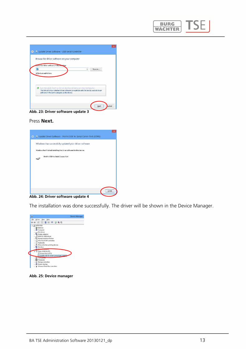
Abb. 23: Driver software update 3
Press Next.
Abb. 24: Driver software update 4
The installation was done successfully. The driver will be shown in the Device Manager.
Abb. 25: Device manager
BA TSE Administration Software 20130121_dp 14
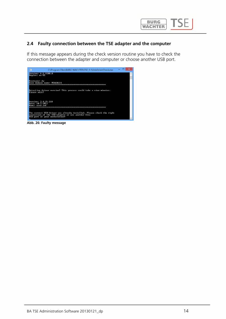
If this message appears during the check version routine you have to check the connection between the adapter and computer or choose another USB port.
Abb. 26: Faulty message
2.4 Faulty connection between the TSE adapter and the computer

BA TSE Administration Software 20130121_dp 15
3 Deactivating of the automatic driver installation in Windows 8
For deactivating of the automatic driver installation you have to place your cursor in the left bottom of the screen and press with the right mouse button the appearing Start window and choose Control panel.
Abb. 27: Windows 8 Start window
Abb. 28: Control Panel
Choose Hardware and sound and then Device and printers.
Abb. 29: Devices and Printers
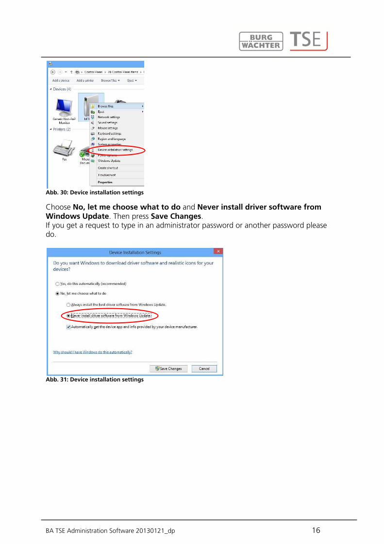
Next choose the name of the computer with the right mouse button then choose Device installation settings
BA TSE Administration Software 20130121_dp 16
Abb. 30: Device installation settings
Choose No, let me choose what to do and Never install driver software from Windows Update. Then press Save Changes. If you get a request to type in an administrator password or another password please do.
Abb. 31: Device installation settings

BA TSE Administration Software 20130121_dp 17
4 Converting a database
You can naturally load also databases of older versions.
A singularity is involved when converting an old database. If you intend to use the software as an update, your old data need to be first converted to the version 4.2c. For this purpose, you have to download the update from www.burg-waechter.de and execute it. The version number of your old software is available under Info of the old software.
Fig. 32: Info
After the update and the installation, perform the following actions. First connect the USB adapter to your computer and then set up the language.
Fig. 33: Selection of language
At this point, the USB adapter is checked. For this purpose, perform the version check first.
Fig. 34: Version check
4.1 Converting from an old database

BA TSE Administration Software 20130121_dp 18
Fig. 35: Selection of database
Fig. 36: Selection to convert the old data
Select the new database directory.
Fig. 37: Selection of folder
Enter the password.
Fig. 38: Entry of password

BA TSE Administration Software 20130121_dp 19
Fig. 39: Local database
Fig. 40: Installation
Fig. 41: End of installation
You have successfully converted the old data. At this point, make the following data settings in order to enable their appropriate transmission. Under the Lock Configuration menu item in the lock list, choose the item Manual Configuration and
select the USB or network adapter intended for the transmission.

BA TSE Administration Software 20130121_dp 20
Fig. 42: Manual lock configuration
determine manually the type of input unit.
In the TSE Input Type tab, double click the label of the input type to open the configuration window.
Fig. 43: Manual setup of the unit type
Enter the appropriate unit type.
Select Apply Changes
When loading an existing database from version 5.0 on, proceed as follows. After the installation, first connect the USB adapter to your computer and then set up the language.
Fig. 44: Selection of language
At this point, the USB adapter is checked. For this purpose, perform the version check
4.2 Loading an existing database
BA TSE Administration Software 20130121_dp 21
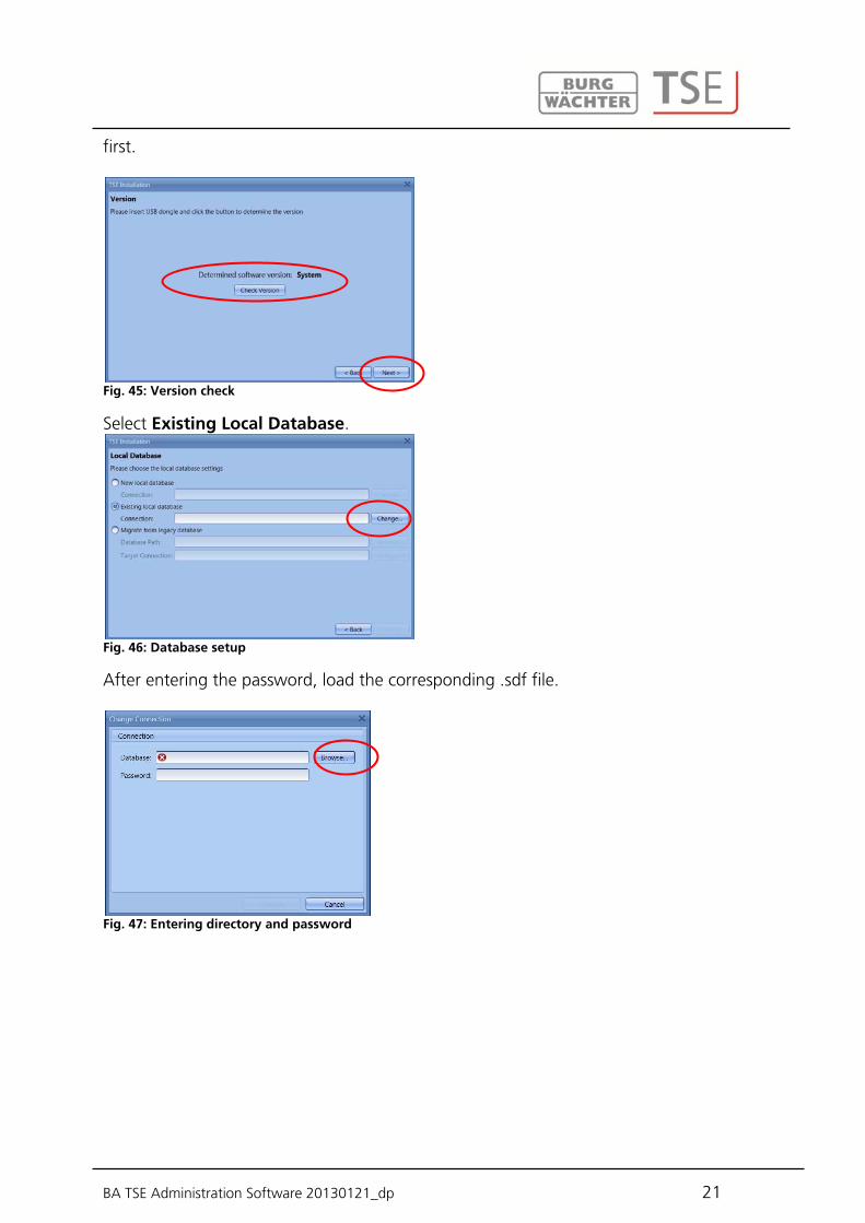
first.
Fig. 45: Version check
Select Existing Local Database.
Fig. 46: Database setup
After entering the password, load the corresponding .sdf file.
Fig. 47: Entering directory and password

BA TSE Administration Software 20130121_dp 22
Fig. 48: Explorer
Fig. 49: Entering directory and password
Fig. 50: Local database
Fig. 51: End of installation
The installation has been completed.
BA TSE Administration Software 20130121_dp 23
5 Data backup and uninstallation
When a backup should be created, the complete TSE folder must be saved. It is located at different places depending on the operating system: Windows XP: C:\Documents and Settings\All Users\Application Files\Burg-Wachter\TSE Windows 7: C:\ProgramData\BURG-WACHTER\TSE Save this folder at another storage location. In case your data is lost, you can restore them in this way. When the software is uninstalled, the user data remain stored.
BA TSE Administration Software 20130121_dp 24
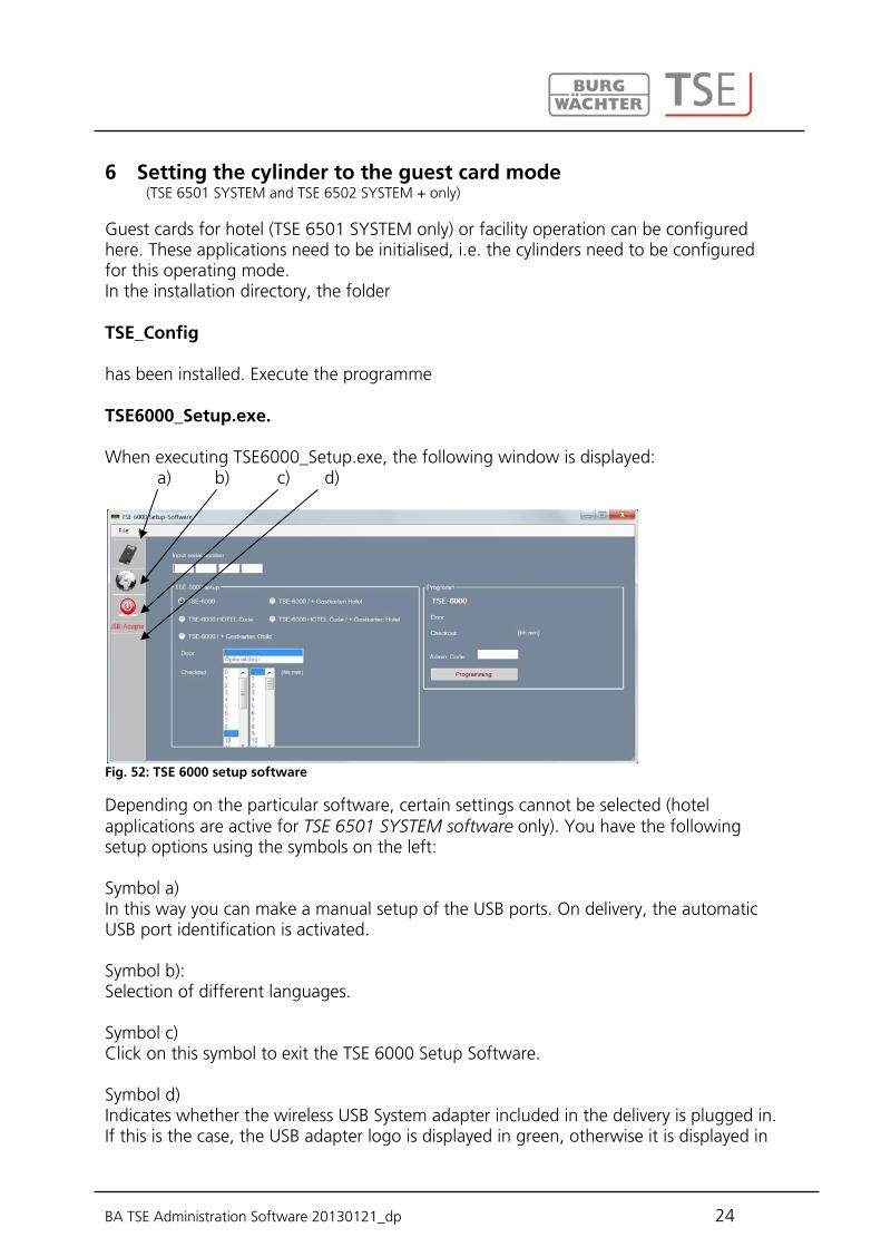
6 Setting the cylinder to the guest card mode (TSE 6501 SYSTEM and TSE 6502 SYSTEM + only) Guest cards for hotel (TSE 6501 SYSTEM only) or facility operation can be configured here. These applications need to be initialised, i.e. the cylinders need to be configured for this operating mode. In the installation directory, the folder TSE_Config has been installed. Execute the programme TSE6000_Setup.exe. When executing TSE6000_Setup.exe, the following window is displayed: a) b) c) d)
Fig. 52: TSE 6000 setup software
Depending on the particular software, certain settings cannot be selected (hotel applications are active for TSE 6501 SYSTEM software only). You have the following setup options using the symbols on the left: Symbol a) In this way you can make a manual setup of the USB ports. On delivery, the automatic USB port identification is activated. Symbol b): Selection of different languages. Symbol c) Click on this symbol to exit the TSE 6000 Setup Software. Symbol d) Indicates whether the wireless USB System adapter included in the delivery is plugged in. If this is the case, the USB adapter logo is displayed in green, otherwise it is displayed in
BA TSE Administration Software 20130121_dp 25
red. The appropriate USB adapter must be plugged in for data transmission!
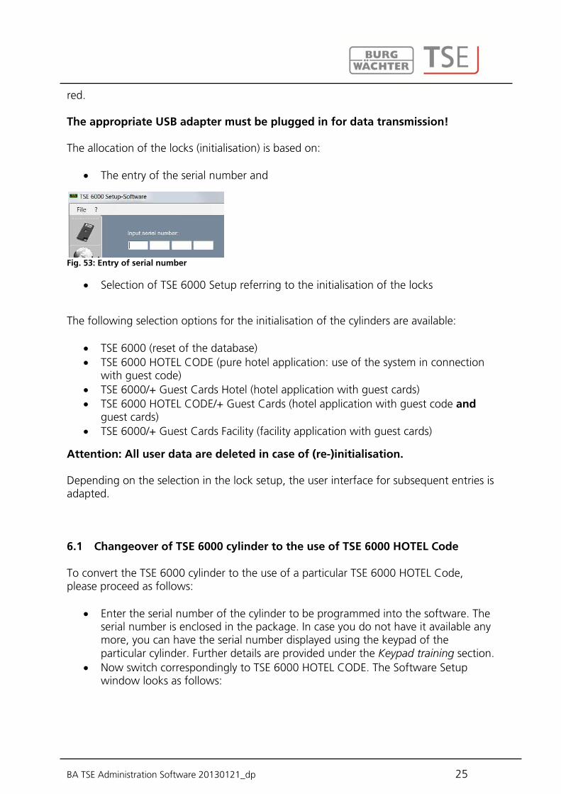
The allocation of the locks (initialisation) is based on:
The entry of the serial number and
Fig. 53: Entry of serial number
Selection of TSE 6000 Setup referring to the initialisation of the locks
The following selection options for the initialisation of the cylinders are available:
TSE 6000 (reset of the database) TSE 6000 HOTEL CODE (pure hotel application: use of the system in connection
with guest code) TSE 6000/+ Guest Cards Hotel (hotel application with guest cards) TSE 6000 HOTEL CODE/+ Guest Cards (hotel application with guest code and
guest cards) TSE 6000/+ Guest Cards Facility (facility application with guest cards)
Attention: All user data are deleted in case of (re-)initialisation. Depending on the selection in the lock setup, the user interface for subsequent entries is adapted.
To convert the TSE 6000 cylinder to the use of a particular TSE 6000 HOTEL Code, please proceed as follows:
Enter the serial number of the cylinder to be programmed into the software. The serial number is enclosed in the package. In case you do not have it available any more, you can have the serial number displayed using the keypad of the particular cylinder. Further details are provided under the Keypad training section.
Now switch correspondingly to TSE 6000 HOTEL CODE. The Software Setup window looks as follows:
6.1 Changeover of TSE 6000 cylinder to the use of TSE 6000 HOTEL Code
BA TSE Administration Software 20130121_dp 26
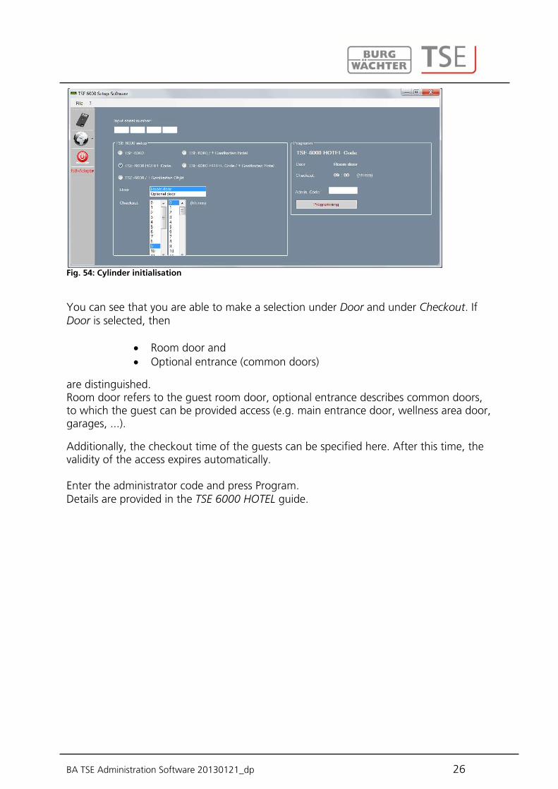
Fig. 54: Cylinder initialisation
You can see that you are able to make a selection under Door and under Checkout. If Door is selected, then
Room door and Optional entrance (common doors)
are distinguished. Room door refers to the guest room door, optional entrance describes common doors, to which the guest can be provided access (e.g. main entrance door, wellness area door, garages, ...).
Additionally, the checkout time of the guests can be specified here. After this time, the validity of the access expires automatically. Enter the administrator code and press Program. Details are provided in the TSE 6000 HOTEL guide.

BA TSE Administration Software 20130121_dp 27
To convert the TSE 6000 CYLINDER to the use of the Guest Cards hotel application, please proceed as follows:
Enter the serial number of the cylinder to be programmed into the software. The serial number is enclosed in the package. In case you do not have it available any more, you can have the serial number displayed using the keypad of the particular cylinder. Further details are provided under the Keypad training section.
Now SWITCH to TSE 6000 / + Guest Cards HOTEL, as appropriate Enter the administrator code and press Program
Fig. 55: Cylinder initialisation
On selection of this guest card application, the fields for the door selection and the selection of the checkout time become automatically inactive. The appropriate setup is made in the software.
6.2 Conversion of TSE 6000 cylinder to the use of TSE 6000/ + hotel Guest Cards

BA TSE Administration Software 20130121_dp 28
The TSE 6000 HOTEL/+ Guest Cards Hotel setup is a combination of the TSE 6000 HOTEL CODE and the TSE 6000/ + Guest Cards Hotel modes. The initialisation is done similarly.
Fig. 56: Cylinder initialization
You recognise that you are able to make a selection under Door and under Checkout. These specifications are important when the cylinders are used for hotel code applications. If guest cards are to be programmed, this allocation is provided in the software. The electronics can automatically distinguish between the two applications. If Door is selected, then
Room door and Optional entrance
are distinguished. Room door refers to the guest room door, optional entrance describes common doors, to which the guest can be provided access (e.g. main entrance door, wellness area door, garages, ...).
Additionally, the checkout time of the guests can be specified here. After this time, the validity of the access expires automatically. When the initialisation is completed, you can start the TSE 6501 Software System.
6.3 Conversion of TSE 6000 CYLINDER to the use of TSE 6000 HOTEL CODE / + Guest Cards Hotel
BA TSE Administration Software 20130121_dp 29
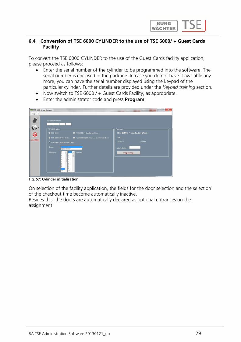
To convert the TSE 6000 CYLINDER to the use of the Guest Cards facility application, please proceed as follows:
Enter the serial number of the cylinder to be programmed into the software. The serial number is enclosed in the package. In case you do not have it available any more, you can have the serial number displayed using the keypad of the particular cylinder. Further details are provided under the Keypad training section.
Now switch to TSE 6000 / + Guest Cards Facility, as appropriate. Enter the administrator code and press Program.
Fig. 57: Cylinder initialisation
On selection of the facility application, the fields for the door selection and the selection of the checkout time become automatically inactive. Besides this, the doors are automatically declared as optional entrances on the assignment.
6.4 Conversion of TSE 6000 CYLINDER to the use of TSE 6000/ + Guest Cards Facility

BA TSE Administration Software 20130121_dp 30
7 Software versions
In the following text, the differences between the individual software versions are described. They differ, for instance, in the type of opening media, or in the number of users. These differences are indicated at the beginning of each chapter. The order of the settings can vary. All the settings can be subsequently maintained and changed. When using TSE 5500 LIGHT and TSE 6501 SYSTEM, the users are assigned to individual locks, for which they posses different authorisations. Using the TSE 6501 software SYSTEM, hotel applications and guest card applications can be used within the facility. By programming the guest cards, a user can be provided with time limited access to various areas. The TSE 6502 software SYSTEM + features client-based administration, which means that different objects (clients) can be administered in parallel. In addition to this, users can be assigned to different groups, i.e. every user is a member of a group, which is then associated with particular locks. Client management and assignment to groups are described directly after the overview. Separate chapters are provided for hotel applications and for administration of safe electronics. Administration of passive transponders is supported by the TSE 6501 software SYSTEM and TSE 6502 software SYSTEM + software. When passive transponders are used, two types are distinguished: the user card or user chip and the guest card or guest chip. All transponder cards supporting the ISO 15693 and ISO 14443 A standards can be used as user cards, while exclusively BURG-WÄCHTER transponder cards or the TSE 6104 CARD can be used as guest cards. The following text always describes the user cards or the guest cards, although both passive transponder systems are compatible with regard to their functionality. The TSE 6203 ENROLLMENT UNIT (not included in the delivery) can be used to train transponder cards and fingerprints in the software. In case you work with guest cards, the locks must be initialised before use in respect of their intended application. All other applications do not require any initialisation.
BA TSE Administration Software 20130121_dp 31
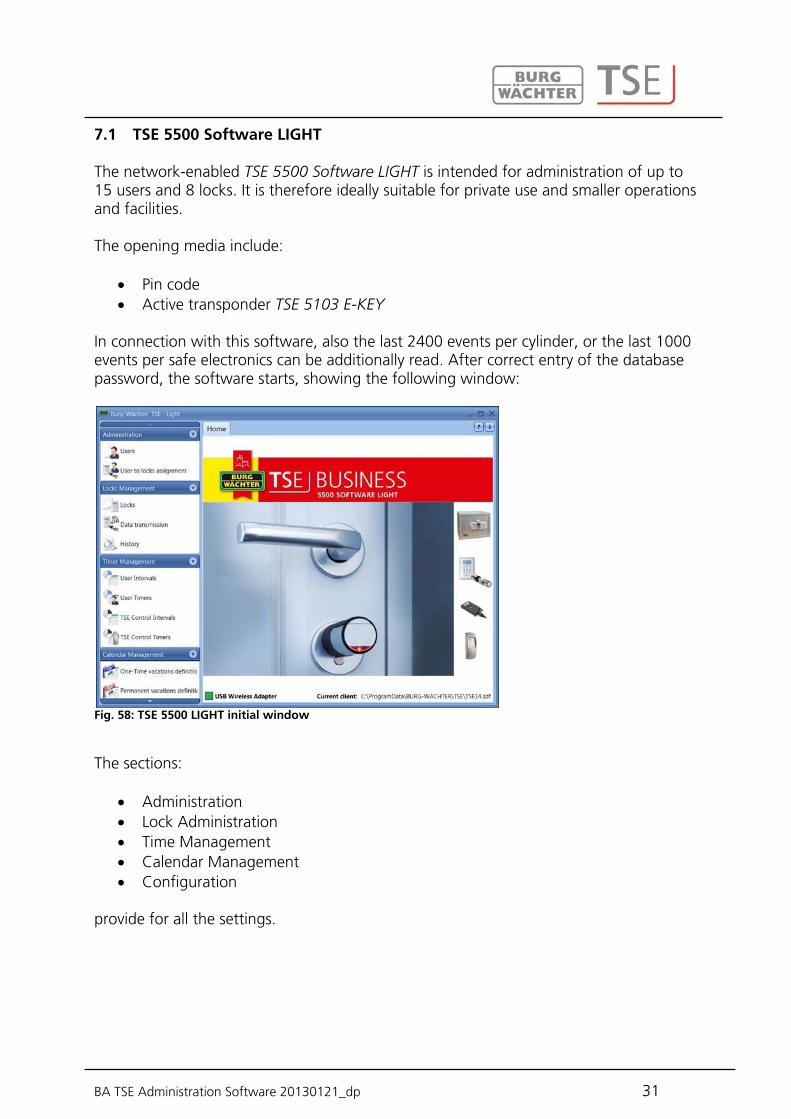
The network-enabled TSE 5500 Software LIGHT is intended for administration of up to 15 users and 8 locks. It is therefore ideally suitable for private use and smaller operations and facilities. The opening media include:
Pin code Active transponder TSE 5103 E-KEY
In connection with this software, also the last 2400 events per cylinder, or the last 1000 events per safe electronics can be additionally read. After correct entry of the database password, the software starts, showing the following window:
Fig. 58: TSE 5500 LIGHT initial window
The sections:
Administration Lock Administration Time Management Calendar Management Configuration
provide for all the settings.
7.1 TSE 5500 Software LIGHT
BA TSE Administration Software 20130121_dp 32
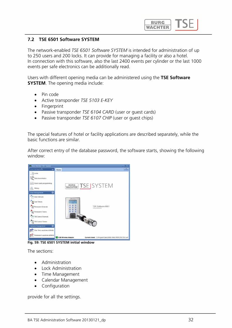
The network-enabled TSE 6501 Software SYSTEM is intended for administration of up to 250 users and 200 locks. It can provide for managing a facility or also a hotel. In connection with this software, also the last 2400 events per cylinder or the last 1000 events per safe electronics can be additionally read. Users with different opening media can be administered using the TSE Software SYSTEM. The opening media include:
Pin code Active transponder TSE 5103 E-KEY Fingerprint Passive transponder TSE 6104 CARD (user or guest cards) Passive transponder TSE 6107 CHIP (user or guest chips)
The special features of hotel or facility applications are described separately, while the basic functions are similar. After correct entry of the database password, the software starts, showing the following window:
Fig. 59: TSE 6501 SYSTEM initial window
The sections:
Administration Lock Administration Time Management Calendar Management Configuration
provide for all the settings.
7.2 TSE 6501 Software SYSTEM
BA TSE Administration Software 20130121_dp 33
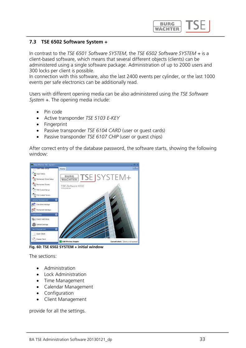
In contrast to the TSE 6501 Software SYSTEM, the TSE 6502 Software SYSTEM + is a client-based software, which means that several different objects (clients) can be administered using a single software package. Administration of up to 2000 users and 300 locks per client is possible. In connection with this software, also the last 2400 events per cylinder, or the last 1000 events per safe electronics can be additionally read. Users with different opening media can be also administered using the TSE Software System +. The opening media include:
Pin code Active transponder TSE 5103 E-KEY Fingerprint Passive transponder TSE 6104 CARD (user or guest cards) Passive transponder TSE 6107 CHIP (user or guest chips)
After correct entry of the database password, the software starts, showing the following window:
Fig. 60: TSE 6502 SYSTEM + initial window
The sections:
Administration Lock Administration Time Management Calendar Management Configuration Client Management
provide for all the settings.
7.3 TSE 6502 Software System +

BA TSE Administration Software 20130121_dp 34
The TSE 6502 Software System + can manage any number of clients. The term client can be replaced by the identification of a particular object (facility). To create a new client or to call up an already existing one, proceed as follows: With the left mouse button, click, as appropriate, the tab Client Management (Mandantenmanagement).
Fig. 61: Client management
Now select between
Create Client (Mandant erstellen) or Open Client (Mandant öffnen)
You can naturally assign a different RFID channel to each client.
After having selected Create Client, the following window is displayed:
Fig. 62: Client wizard
To create a new client, proceed as follows:
Determine whether a local client or an SQL client shall be created. In case of an SQL client, the file is located on a server, as opposed to a local client.
The software proposes a storage location for your data. You also have an
7.3.1 Creating / opening clients
7.3.2 Creating new client

BA TSE Administration Software 20130121_dp 35
opportunity to determine it yourself. For this purpose click the folder symbol and choose the storage location.
The default location is: Windows XP: C:\Documents and settings\All Users\Application files\Burg-Wachter\TSE Windows 7: C:\ProgramData\BURG-WACHTER\TSE The client is saved here with the.sdf suffix.
Specify a password in order to protect your data. This password must contain at least three characters.
Define the number of user groups, which are expected to be administered for the particular client. User groups can be subsequently added or deleted without problems. The maximum number is 50.
Choose the RFID channel, on which communication within the client should take place.
After that, please press the Create Client button in the bottom right section of the window.
Under this menu item you can open an already existing client, for example in order to
make changes in it. Use the button to choose the appropriate path and file and confirm your authorisation by entering your password. Attention: In case you have allocated safe electronics to the particular client, the data and the software must be started from a removable data carrier. If you try to load a client from your hard disk, you will receive an error message. The client cannot be opened!
7.3.3 Opening existing client

BA TSE Administration Software 20130121_dp 36
8 Software structure
The initial window is displayed after the programme is started.
Fig. 63: Initial window
A green square in the bottom left screen area indicates that a valid USB adapter is connected to the computer, a red square means that either no USB adapter has been plugged or the drivers have not been installed appropriately. In case a yellow square is indicated, a USB adapter invalid for the particular software is plugged in (e.g. an adapter intended for the TSE Software System). The system automatically recognises whether a USB adapter applicable for the particular software is plugged. On the left, all the categories are displayed, and they can be selected by clicking the right mouse button. The software type is indicated in the header line. For the purpose of this documentation, the windows from the TSE 6502 Software SYSTEM + are used. However, the functions are similar for the other types of software.

BA TSE Administration Software 20130121_dp 37
The categories include:
Administration Lock Administration Time Management Calendar Management Configuration Client Management (for TSE 6502 Software SYSTEM + only)
The categories are subdivided into different subcategories. They are described in detail in the subchapters.
The chapter on configuration describes both the general program settings and the parameters for the guest card (TSE 6501 System and TSE 6502 System +).
In this menu item, the general settings are made. Also administrator codes are maintained here, as well as the data for the connected adapters and additional equipment (e.g. TSE Network Adapter) or the language. The following window appears after selection.
Fig. 64: Default settings
Under the item General information on the connected USB adapter and its status is provided. An automatic identification is preset as the default value. If you wish to change the COM port manually, you should perform a test by pressing the appropriate button. The message Test successful or Test failed provides the corresponding information. If the test fails, the manually entered COM port needs to be changed.
8.1 Configuration
8.1.1 Default Settings

BA TSE Administration Software 20130121_dp 38
Fig. 65: Manual COM port value
The USB wireless adapter for the software is always indicated under the reference of Progstation in the list and this cannot be changed. The network adapters are products TSE 6204 ADAPTER TCP/IP in connection with the TSE 6205 NETWORK UNIT. They are used in case data transmission should cover longer distances within a building or from or to another building or external area. A typical operating range of a USB adapter is up to 20 m. This value depends on the surrounding environment and can vary in both directions. In case of doubt this should be tested within the facility. The TSE 6204 ADAPTER TCP/IP can be connected to a USB for a TCP/IP converter (e.g. W & T). Together with the internal software of these devices, corresponding communication is possible. The adapter intended for communication with a particular lock is selected in the Door Lock Adjustment menu. The TSE 6205 NETWORK UNIT with an integrated TCP/IP adapter is an already preconfigured unit for these applications. The network-enabled units must be configured separately and are not included in the delivery. The Update button can be used to display all the USB adapters available within the network. The status indication informs on whether the particular USB adapter is active (green bar) or inactive (red bar). If network wireless adapters are found, the network adapter assigned based on lock settings is selected for data transmission and it is then used for forwarding the data to the particular lock. The name can be specified individually by selecting the corresponding field by double clicking it in the Naming column (excluding Progstation). The field COM indicates the COM port (maximum number of available COM ports: 99), to which the software adapter is connected. Additionally, the wireless channel for data transmission is specified. This is of fundamental importance, as the RFID channel selected here defines the channel setup of the executive unit. Channel 1 is always preset as a default value. If another channel is selected for data transmission, it is used automatically when data transmission takes place. Data transmission is executed in the newly defined channel and it is applicable to all the locks. Attention: The new RFID channel should be, if available, adjusted in advance using the keypad. Please find detailed instructions in the manual provided with the keypad. For this purpose the menu item RFID Channel Admin Settings shall be selected. The RFID channel can be changed after entering the administrator code. The RFID channel indicated on the keypad display must correspond to the

BA TSE Administration Software 20130121_dp 39
channel selected in the software. Otherwise data transmission is not possible. Similarly, all the TSE 6103 E-KEYs or TSE 6202 SWITCH units must be adjusted to this RFID channel. In case other devices (e.g. W-LAN, Bluetooth, Bluetooth Headsets, etc.) interfere with wireless transmission, an RFID channel with a distance of at least 3 channels should be selected. The specifications have to be saved. With regard to the Administration menu item, the software types are different. In the TSE 5500 Software LIGHT, different history passwords are missing when compared to the other software versions TSE 6501 SYSTEM and TSE 6502 SYSTEM +.
Fig. 66: Administration for TSE 5500 LIGHT
The TSE 6501 SYSTEM and TSE 6502 SYSTEM+ software are identical with regard to the administration. Additional management of administrator and history passwords is provided here.
BA TSE Administration Software 20130121_dp 40
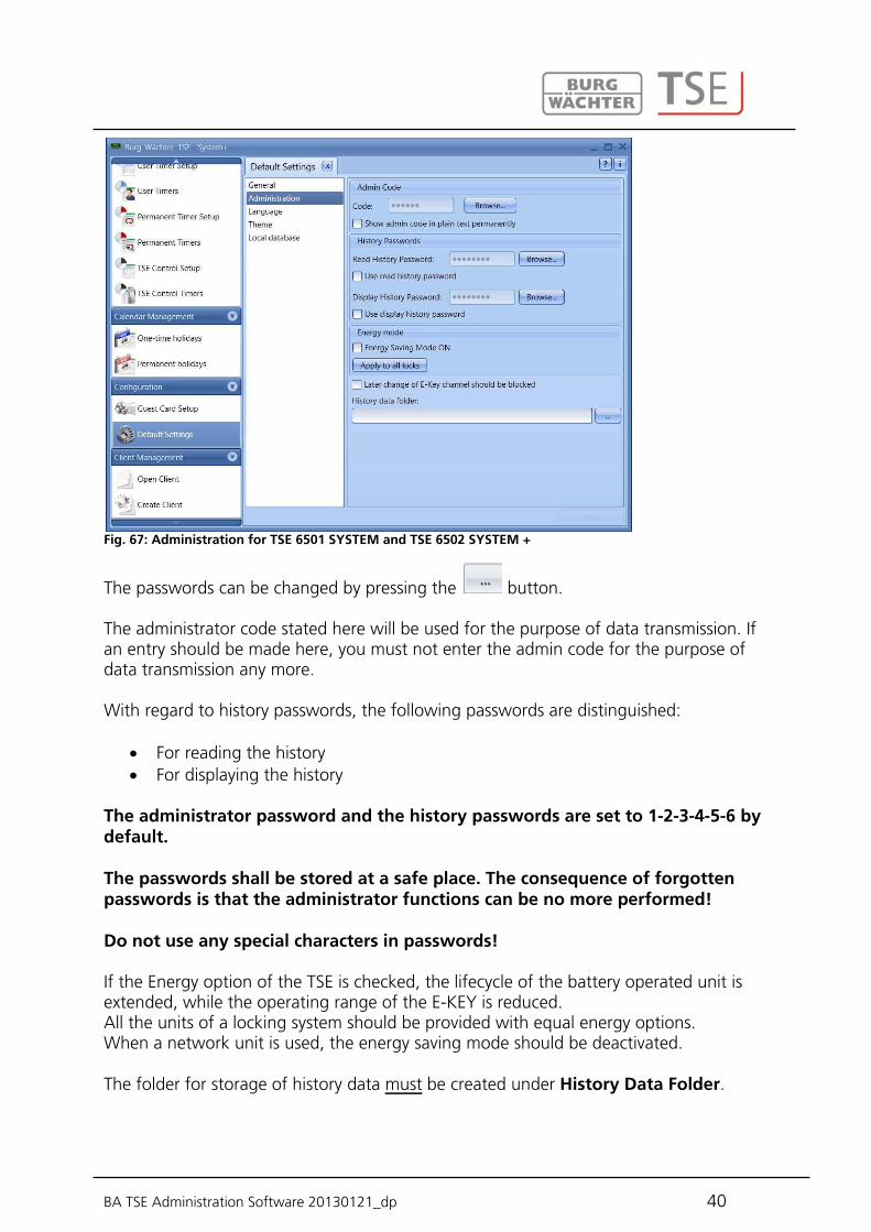
Fig. 67: Administration for TSE 6501 SYSTEM and TSE 6502 SYSTEM +
The passwords can be changed by pressing the button. The administrator code stated here will be used for the purpose of data transmission. If an entry should be made here, you must not enter the admin code for the purpose of data transmission any more. With regard to history passwords, the following passwords are distinguished:
For reading the history For displaying the history
The administrator password and the history passwords are set to 1-2-3-4-5-6 by default. The passwords shall be stored at a safe place. The consequence of forgotten passwords is that the administrator functions can be no more performed! Do not use any special characters in passwords! If the Energy option of the TSE is checked, the lifecycle of the battery operated unit is extended, while the operating range of the E-KEY is reduced. All the units of a locking system should be provided with equal energy options. When a network unit is used, the energy saving mode should be deactivated. The folder for storage of history data must be created under History Data Folder.

BA TSE Administration Software 20130121_dp 41
In case no specification is entered here, data transmission with parallel history reading will fail.
Select the button for this purpose. It would be reasonable to create the folder within the installation path: Windows XP: C:\Documents and settings\All Users\Application files\ Burg-Wachter\TSE Windows 7: C:\ProgramData\BURG-WACHTER\TSE The Language menu item provides, on one hand, for selecting the software language, and, on the other hand, for selecting an additional language for the keypad, so that the use of the keypad can be based on the local language.
Fig. 68: Default settings for language
For this purpose, use the pop-up menu to select the desired language and place a check under Language to be added on next programming action. Under the Local Database item, you can change the password of the local database, if such a database had been specified as the storage location. Under the Local Database item, the database password can be changed. For this purpose, first enter the old administrator code, and then specify a new one.

BA TSE Administration Software 20130121_dp 42
(TSE 6501 SYSTEM and TSE 6502 SYSTEM + only) You need this function only when using time-limited (passive) transponders. Two types are distinguished: user cards and guest cards. A user card is a transponder, which is used to open the locks, for instance as a pin code. Timer and calendar functions can be assigned to this transponder and they are valid from the date of their registration in the system to the moment of their active removal from the system. Guest cards have a different behaviour. They are also transponders used to open the locks, however, their validity is restricted to a defined period of time (e.g. from 02.03. to 03.03.10 or on 15.02.10 from 08:00am to 05:00pm). Afterwards, their validity automatically expires. Guest cards are transponders providing a time-limited access to defined areas to a hotel guest or a visitor group. When this time window expires, the transponder becomes invalid, and no further access to the corresponding areas is possible. The following window appears after selecting the Guest Card Settings menu:
Fig. 69: Guest card settings for TSE 6502 SYSTEM +
The following basic settings can be made here: Start/end of access time Offset
In total, four different offsets can be set. The variances to the access times indicated above, can be defined based on the offsets. In this way, the transponders can be actively assigned start or end times extended
8.1.2 Guest card settings

BA TSE Administration Software 20130121_dp 43
beyond and/or restricted to shorter access authorisations. Supposing a (validity) end time is set to 05:00pm, an offset of +1:00 hours can provide for access till 06:00pm. In both hotel and facility modes, these variances apply solely to the first and last day of validity. Offset has no influence on the days between them. The time range as specified here applies to all doors managed within the system. These basic settings can be changed individually at any time by programming of the card; this process will not substantially affect the basic settings themselves (see also chapter Guest card programming). Example: 8:00am is specified as the start time, the end time is 5:00pm. In case no variances from these times are granted, no offset needs to be defined. The data can be saved. Offsets are to be defined as follows:
Select the Add offset button. Use the Start/End column to determine whether the start or end time should be
changed using offset. Specify the required variance in the Offset column.
A description for a particular offset value can be entered by double clicking the Offset line.
Fig. 70: Determining offset times
In this example, the offset value indicates that the access authorisation time is extended from 5:00pm to 6:00pm. Attention: All doors authorised by means of a guest card are subject to access authorisations assigned for the timer. Doors, for which another access authorisation should apply and which are, however, specified on the

BA TSE Administration Software 20130121_dp 44
transponder card, have to be deactivated in the Lock Settings menu based on timer settings, i.e.: timers do not apply to this lock. In the TSE 6501 Software SYSTEM, management of hotel operations based on guest cards is possible. As a result, these settings involve an extended function: the Hotel and Facility modes are distinguished.
Fig. 71: Guest card settings for TSE 6501 SYSTEM
In case you choose the Facility mode, the guest cards are created similarly to the procedure described in chapter Guest card programming. 8.1.2.1 Hotel mode (TSE 6501 SYSTEM only) In principle, administration of guest cards for facilities differs from the one for hotel applications in a few aspects only. They include:
Definition of visitor groups Initialisation Way of assignment of doors Card loss
The general procedure of the setup is identical. Different is the procedure in the Locks submenu within lock management. An additional column is active here, in which
Room number, and Optional entry
must be distinguished.

BA TSE Administration Software 20130121_dp 45
8.1.2.2 Assignment of doors (TSE 6501 SYSTEM only) In order to make all the settings for guest card management in hotel industry, also lock administration settings in the lock submenu need to be provided. An additional column is active here, in which
Room number, and Optional entry
must be distinguished.
Fig. 72: Assignment of doors
In addition, all the locks need to be initialised. For this purpose, select the appropriate locks and right click them to initialise them.
Fig. 73: Initialisation for hotel mode
Optional entries are those to which the guest should be granted access, however, which are not his/her room doors. They can include for example common areas such as wellness or fitness facilities. In case of hotel applications, at least one room door must be selected in the door mode column.

BA TSE Administration Software 20130121_dp 46
8.1.2.3 Card loss in hotel applications (TSE 6501 SYSTEM only) In case a guest card in the hotel mode gets lost, all the locks, to which the guest had access, must be newly initialised. For this purpose, select the appropriate locks, to which the guest should be granted access, and right click them to initialise them. After this, the guest card has to be newly programmed. To do this, newly define the corresponding access authorisations and the access period, and program a new card. Attention: The old card does not become invalid and unusable for further access before the door has been opened using the new guest card for the first time. All doors to which the old card authorised access need to be opened once using the new card.

BA TSE Administration Software 20130121_dp 47
In this item, the software types differ with regard to their functionality. The TSE 5500 LIGHT and TSE 6501 SYSTEM software packages are structured similarly. The users are assigned to the required doors here. This is done in the Lock Assignment menu. In the TSE 6502 Software SYSTEM +, the users are firstly assigned to groups, which are then assigned to particular locks in their turn. First, users created and then the opening media such as a pin code or a TSE 6103 E-KEY or also a passive transponder and fingerscan (for TSE 6501 and TSE 6502 only) are defined.
Via the icon the user administration can be opened. The individual users can be edited here.
Fig. 74: User administration
Users can be added or deleted using the User+ and User– buttons. When the Details+ button is selected, an editing window for the particular user appears.
8.2 Administration
8.2.1 Users

BA TSE Administration Software 20130121_dp 48
Fig. 75: User information
All the data related to the individual user can be specified here including an image file (max. resolution 640 x 480). The reference in the Nickname column is generated automatically by the system and it is composed of the three initial letters of the first name and of the surname. This nickname is then displayed when the data has been transferred to the keypad and for the purpose of history. Should several users with identical initials occur, the system creates automatically a suffix with a sequential number. Many of the settings available here can be also made or changed directly in the line of the corresponding user by selecting the appropriate field by double clicking it. Moreover, this function is not only intended for creation and configuration of users, but also for instance for definition of particular rights and opening codes assigned to individual users. Besides this, additional opening media such as active or passive transponders and timers for limited access can be allocated to a user. The pin codes are not openly displayed for the sake of security. However, the specific code becomes visible when selected by the mouse button. The following table provides information on the individual entry options, with detailed information in subchapters: Selection fields Entry/selection options First name e.g. Walter Surname e.g. Schmidt Timer - (no timer)
List of the timers defined in the time management Right 1 Full individual access right
1/2 Access only with an additional opening authorisation of 1/2 1/3 Access only with an additional opening authorisation of min. 1/3
BA TSE Administration Software 20130121_dp 49
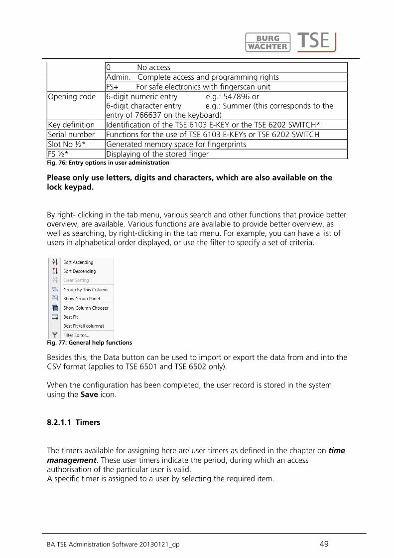
0 No access Admin. Complete access and programming rights FS+ For safe electronics with fingerscan unit
Opening code 6-digit numeric entry e.g.: 547896 or 6-digit character entry e.g.: Summer (this corresponds to the entry of 766637 on the keyboard)
Key definition Identification of the TSE 6103 E-KEY or the TSE 6202 SWITCH* Serial number Functions for the use of TSE 6103 E-KEYs or TSE 6202 SWITCH Slot No ½* Generated memory space for fingerprints FS ½* Displaying of the stored finger Fig. 76: Entry options in user administration
Please only use letters, digits and characters, which are also available on the lock keypad. By right- clicking in the tab menu, various search and other functions that provide better overview, are available. Various functions are available to provide better overview, as well as searching, by right-clicking in the tab menu. For example, you can have a list of users in alphabetical order displayed, or use the filter to specify a set of criteria.
Fig. 77: General help functions
Besides this, the Data button can be used to import or export the data from and into the CSV format (applies to TSE 6501 and TSE 6502 only). When the configuration has been completed, the user record is stored in the system using the Save icon. 8.2.1.1 Timers The timers available for assigning here are user timers as defined in the chapter on time management. These user timers indicate the period, during which an access authorisation of the particular user is valid. A specific timer is assigned to a user by selecting the required item.
BA TSE Administration Software 20130121_dp 50
8.2.1.2 Rights The (access) rights are configured and assigned to the individual users in the Users menu. In the rights management, a total value of exactly 1 must be achieved for access authorisation. From version 2.8 of the executive unit, the opening is allowed also in case the value of 1 is exceeded.
1 Full individual access right 1/2 Access only with an additional opening authorisation of ½ 1/3 Access only with an additional opening authorisation of min 1/3 0 No access Admin. Complete access and programming rights FS+ For safe electronics with fingerscan unit
The right FS+ shall be selected only for safe electronics version 1.0 in combination with fingerscan. With higher versions, the authorisation to open safe electronics with fingerscan is based on the authorisation rights. The value of fingerscan is automatically set to ½ for safe electronics with fingerscan. The authorisation to open a safe can then be reached in combination with an additional user with a similar half value or with two users with values of 1/3. TSE E-KEYs, fingerscans and transponders have the same access rights as indicated in the user administration as the corresponding right. 8.2.1.3 Key ID Under the KeyID item, both active (TSE 6103 E-KEY) and passive (TSE 6104 card or TSE 6107 chip) transponders, as well as TSE 6202 SWITCH can be administered. In case a change of the RFID channel occurs, it is also possible to newly synchronise an E-KEY or a TSE SWITCH. The TSE 5500 Software LIGHTincludes a restriction: Only TSE 6103 E-KEYs can be administered.

BA TSE Administration Software 20130121_dp 51
Fig. 78: Variants of KeyID assignment
The following individual options are available using the left mouse button, which are selectively discussed below:
Store E-KEY/SWITCH and transponder Delete Cut Paste Search for E-KEY/SWITCH and transponder Synchronise E-KEY/SWITCH
BA TSE Administration Software 20130121_dp 52
8.2.1.4 Storing E-KEY/SWITCH This subchapter describes the storing of the TSE 6103 E-KEY and the TSE 6202 SWITCH. The TSE 6202 SWITCH is a switching unit, using which TSE units (TSE Cylinder, TSE 6201 CONTROL) can be controlled by means of a management and control unit provided. When storing a TSE 6103 E-KEY or a TSE 6202 SWITCH, it is necessary to identify first, whether this is a unit without any prior E-KEY or TSE SWITCH assignment, or whether the E-KEY or the TSE SWITCH is already in use and had already been assigned to a lock at least once. If the E-KEY has not been trained for any unit yet, you have to press the button on the E-KEY only once and the LED flashes three times. The TSE SWITCH is to be briefly energised correspondingly during this period. If a TSE 6103 E-KEY or a TSE 6202 SWITCH is to be assigned, which had already been assigned to a unit before, it shall be brought into the programming mode by pressing the button for approximately 10 s. When this mode has been achieved, the LED on the TSE 6103 E-KEY flashes three times briefly. The TSE SWITCH is to be briefly energised correspondingly during this period. To break in an E-KEY/SWITCH, proceed as follows:
Select the KeyID field, and a popup window opens Break in => select E-KEY/SWITCH
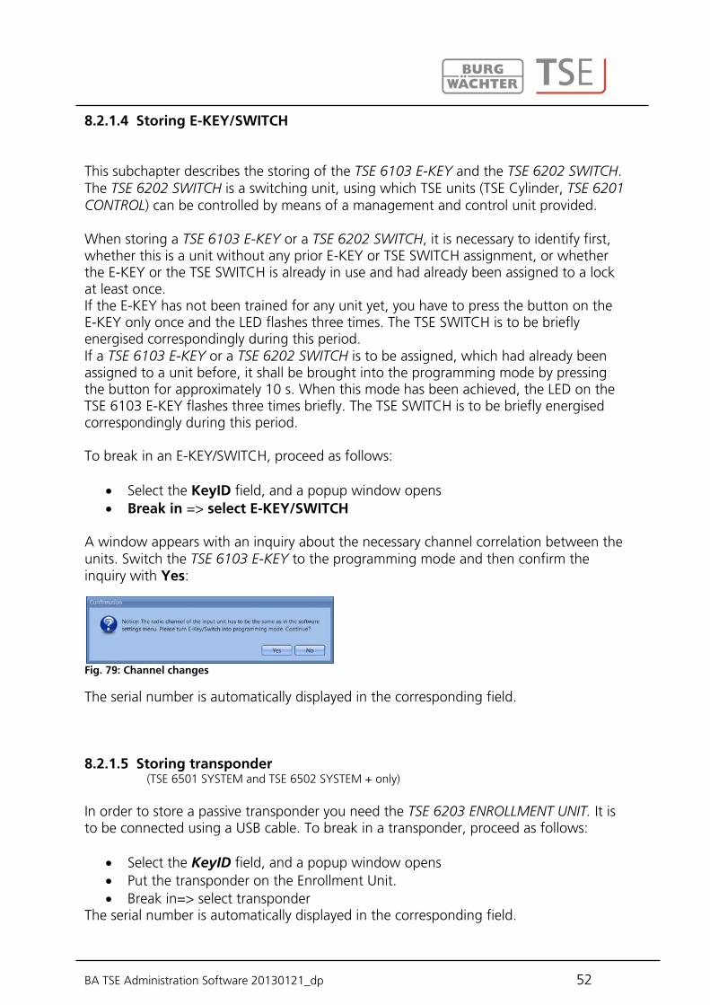
A window appears with an inquiry about the necessary channel correlation between the units. Switch the TSE 6103 E-KEY to the programming mode and then confirm the inquiry with Yes:
Fig. 79: Channel changes
The serial number is automatically displayed in the corresponding field. 8.2.1.5 Storing transponder (TSE 6501 SYSTEM and TSE 6502 SYSTEM + only) In order to store a passive transponder you need the TSE 6203 ENROLLMENT UNIT. It is to be connected using a USB cable. To break in a transponder, proceed as follows:
Select the KeyID field, and a popup window opens Put the transponder on the Enrollment Unit. Break in=> select transponder
The serial number is automatically displayed in the corresponding field.

BA TSE Administration Software 20130121_dp 53
8.2.1.6 Searching for E-KEY/SWITCH In order to identify the owner of a TSE E-KEY/SWITCH, please proceed as follows:
Click the KeyID field, and a popup window opens Select E-KEY/SWITCH search
A window is displayed containing an instruction to switch the TSE 6103 E-KEY to the programming mode.
Switch the TSE 6103 E-KEY to the programming mode (by pressing the button on the TSE 6103 E-KEY for approximately 10 s until the green LED flashes three times in a row) and then confirm the inquiry with Yes.
Confirm the inquiry with Yes
The appropriate user is indicated in the window.
8.2.1.7 Searching for transponder (TSE 6501 System and TSE 6502 System + only) In order to identify the owner of a transponder, please proceed as follows:
Click the KeyID field, and a popup window opens Select the transponder search Put the transponder on the Enrollment Unit.
The appropriate user is indicated in the window. 8.2.1.8 Synchronise E-KEY/SWITCH In case the system RFID channel has been changed after the programming, all the relevant TSE 6103 E-KEYs or TSE 6202 SWITCH have to be adjusted to the newly active system RFID channel, the units have to be synchronised. In order to indicate this visually in the software, the serial number of the TSE 6103 E-KEY in the user administration window is displayed in red. The following procedure needs to be adopted:
Click the KeyID field, and a popup window opens Select Synchronise E-KEY/SWITCH A window is displayed containing an instruction to switch the TSE 6103 E-KEY to the programming mode. SWITCH the TSE 6103 E-KEY to the programming mode (by pressing the button
on the TSE 6103 E-KEY for approximately 10 s until the green LED flashes three times in a row) and then confirm the inquiry with Yes.
The colour of the serial number changes from red to black and, besides that, a message
BA TSE Administration Software 20130121_dp 54
is displayed that the adjustment was successful. If a channel adjustment for a TSE 6103 E-KEY or a TSE 6202 SWITCH should not be synchronised yet and the original values should be restored, you can use the function Reset all E-KEY/SWITCH designations. In such case, the indication (in red) is simply reset to black. The function Synchronise E-KEY/SWITCH would lead to the same result. Before creating the TSE 6103 E-KEY or the TSE SWITCH, the RFID channel of the lock must be specified in the software. It must correspond to the keyboard RFID channel. It is necessary to take into account that a TSE 6103 E-KEY or a TSE 6202 SWITCH can be created always for a single user only at a time. From version 2.8 of the TSE 3004 executive unit and for all the TSE 5000/6000 versions, also the TSE 6103 E-KEY or the TSE SWITCH are subject to the settings made under the User administration menu item with regard to access authorisations. In case a user is assigned a code and a TSE 6103 E-KEY and the right ½ in the user administration, he/she nevertheless needs an additional user in order to achieve an opening right of at least 1. He/she is still not allowed to open with the TSE 6103 E-KEY and code, although his/her total makes a value of 1. 8.2.1.9 Fingerprint administration (TSE 6501 SYSTEM and TSE 6502 SYSTEM + only) Attention: The fingerprint administration relates only to door locks and thus cannot be used for programming of safe locks. Fingerscans, which should be programmed into a safe, must be saved directly on the fingerscan readout unit of the safe lock! Using the TSE 6501 SYSTEM and TSE 6502 SYSTEM+ software versions, different numbers of fingerprints can be administered: TSE 6501 System: 250 fingerprints TSE 6502 System +: 400 to 600 fingerprints can be administered (from cylinder version
1.7 and keypad 4.9) However, for this purpose, in order to record the fingerprints to the lock by means of the software, the keypad should be registered using the Configuration menu item. Up to 45 premium fingers can be assigned per TSE lock depending on the fingerscan version. When an update process is started, a warning message is generated when the number of premium fingers is exceeded, notifying on a correction in assignment.
BA TSE Administration Software 20130121_dp 55
The following types are distinguished:
Premium finger Standard finger
This discrimination has no influence on the authorisation, it is rather intended for a faster evaluation. Premium fingers are preferred during verification and, thanks to a simpler operation, they are easier to use. They are fingers, which authorise to open the lock with no additional entry of a verification code. In case of a standard finger, an additional verification code (slot No), as determined by the system, must be entered using the keypad. The leading zeros do not need to be entered. The verification code is indicated in the column Slot No 1 or Slot No 2. For a standard finger, the entry on the keypad is made as follows:
1. Press the On/Enter key on the keypad 2. Specify the slot No 3. Press Enter 4. Move the finger over the sensor
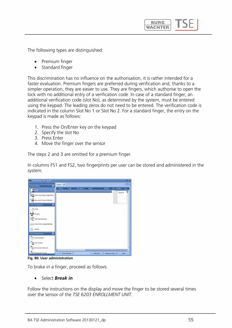
The steps 2 and 3 are omitted for a premium finger. In columns FS1 and FS2, two fingerprints per user can be stored and administered in the system:
Fig. 80: User administration
To brake in a finger, proceed as follows:
Select Break in
Follow the instructions on the display and move the finger to be stored several times over the sensor of the TSE 6203 ENROLLMENT UNIT.

BA TSE Administration Software 20130121_dp 56
Fig. 81: ENROLLMENT UNIT 1. Finger break in process
When the finger has been stored, you can define the finger and save it with OK
Fig. 82: Finger definition
Select Close (Schließen). The finger is initially saved as a standard finger (the
symbol is indicated in the table).
Fig. 83: User administration
If you intend to define the finger as a premium finger, you have to use the functions provided by the right mouse button in the FS section and select Premium. The symbol
in the FS column then changes from to . Apart from this, the Finger Number Slot is displayed in the Description column. Attention: When opening with a standard fingerscan, the fingerprint identification must be accompanied by a specification of the slot number.

BA TSE Administration Software 20130121_dp 57
(TSE 5500 LIGHT and TSE 6501 SYSTEM only) In the TSE 5500 Software LIGHT and TSE 6501 Software SYSTEM, the users are directly
assigned to the individual locks. The button can be used to open the following window in case no user has been created yet:
Fig. 84: Lock assignment
In case users have already been created, all the users are listed in a corresponding column.
Fig. 85: Function type
8.2.2 Lock assignment

BA TSE Administration Software 20130121_dp 58
A popup menu can be opened by double clicking under the corresponding group, from which you can choose the type of function. With the TSE 5500 Software LIGHT, the following can be distinguished:
Operation without opening authorisation Operation with code only
With the TSE 6501 Software SYSTEM, the following can be distinguished:
Operation without opening authorisation Operation with code only Operation with one fingerprint Operation with two fingerprints Operation with a code and one fingerprint Operation with a code and two fingerprints
Attention: This discrimination provides no information on the right for individual opening (see Users for details). For example, operation with two fingerprints only implies that two fingerprints have been saved, and two fingerprints and a code mean that a (pin) code has additionally been saved. If you assign operation with a code and one or two fingerprints to a user, please take into account that two user places are automatically used internally. In this way, you can provide a user with different opening options for different locks. A subsequent modification is possible at any time. In case a red cross with a white x is displayed when you make the assignment, this means that the assignment does not correspond to a previously entered specification. When you move the cursor over this symbol, the related error message is displayed. In such case, please correct your specifications. When the configuration has been completed, the user record is stored in the system using the Save icon.
(for TSE 6502 Software SYSTEM + only) In this menu, users are assigned to groups, which can then be assigned to locks. With the TSE 6502 Software SYSTEM +, users are assigned to particular locks based on
groups. The button can be used to open the following window in case no user has been created yet:
8.2.3 Group assignment
BA TSE Administration Software 20130121_dp 59
Fig. 86: Group assignment
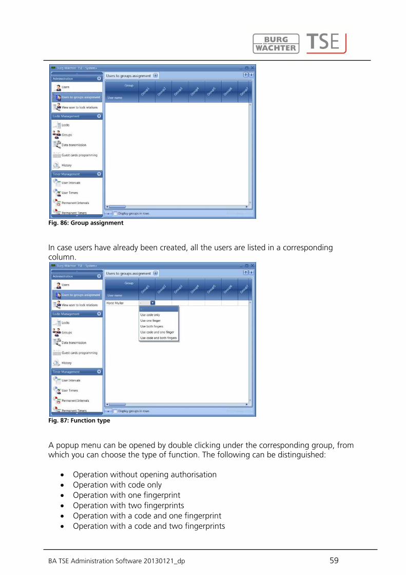
In case users have already been created, all the users are listed in a corresponding column.
Fig. 87: Function type
A popup menu can be opened by double clicking under the corresponding group, from which you can choose the type of function. The following can be distinguished:
Operation without opening authorisation Operation with code only Operation with one fingerprint Operation with two fingerprints Operation with a code and one fingerprint Operation with a code and two fingerprints

BA TSE Administration Software 20130121_dp 60
Attention: This discrimination provides no information on the right for individual opening (see Users for details). For example, operation with two fingerprints only implies that two fingerprints have been saved, and two fingerprints and a code mean that a (pin) code has additionally been saved. If you assign operation with a code and one or two fingerprints to a user, please take into account that two user places are automatically used internally. In this way, you can provide a user with different opening options within different groups. For example, you can assign three different groups to the user Horst Müller. In the first group, he can open the corresponding locks by code only, in group 3 with one fingerprint only, and in group 10 with two fingerprints.
You can naturally also edit the groups first using the menu item . A subsequent modification is possible at any time.
Fig. 88: Lock assignment
In addition, you can use the button to export the data in the CSV format. When the configuration has been completed, the user record is stored in the system using the Save button.
(for TSE 6502 Software SYSTEM + only) This menu item provides a complete listing of assignments of individual groups to locks. Editing is not possible here as changes need to be made under the appropriate menu items. Individual groups only can be deleted here.
In addition, you can use the button to import or export the data in the CSV format or to print them.
8.2.4 Overview of group assignments
BA TSE Administration Software 20130121_dp 61
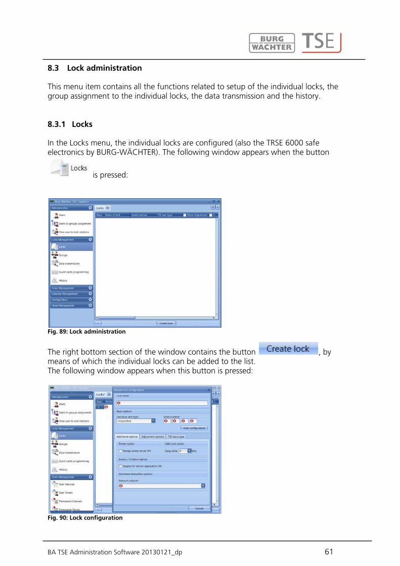
This menu item contains all the functions related to setup of the individual locks, the group assignment to the individual locks, the data transmission and the history.
In the Locks menu, the individual locks are configured (also the TRSE 6000 safe electronics by BURG-WÄCHTER). The following window appears when the button
is pressed:
Fig. 89: Lock administration
The right bottom section of the window contains the button , by means of which the individual locks can be added to the list. The following window appears when this button is pressed:
Fig. 90: Lock configuration
8.3 Lock administration
8.3.1 Locks

BA TSE Administration Software 20130121_dp 62
All the marked fields are mandatory fields, the checked fields present basic settings, which are first explained. The entry fields in the Lock Configuration (Schlosskonfiguration) window are treated separately in various subchapters, as their function is of fundamental importance. The individual functions can be deactivated by selecting them, and their checking disappears.
Timer Settings; if deactivated, the lock is not subject to the settings entered in the Time Management window.
Calendar Settings; if deactivated, the lock is not subject to the settings entered in the Calendar window.
Code Change; if deactivated, the user cannot change his/her code any more. Adopt PC Time Settings; the PC time settings are assumed whenever a data
transfer takes place. MESZ; an automatic changeover from summer to winter time and vice versa.
Additional fields can be activated or preset: In the Priority Definition selection field, you have an opportunity to influence
the response characteristics of the lock when the TSE 6103 E-KEY is used. When the TSE 6103 E-KEY is programmed into several neighbouring doors and the appropriate door is not opened when the E-KEY is used, you can increase the priority of this door or decrease the priority of the door opened incorrectly. The default value is 3, the highest priority is 5, the lowest 1.
An adjustment of this value is usually not necessary. The Permanent Timer and Offset Timer selection fields are used to determine
whether the times defined under the Time Management menu are active or not for the particular lock.
A complete lock consist of an executive unit (cylinder) or, as the case may be, a control unit (TSE 6201 CONTROL) and, in many cases, of an associated input unit (TSE keypad) or a TSE CARD READER. An exception are units controlled by the TSE 6103 E-KEY (active transponder) only. Only the TSE cylinder is provided in these cases. The two units need to communicate with each other and therefore they need to be mutually registered. The registration can be made in advance or can be already provided for units of the TSE 5000 series, however, it can or even must be made by the software for certain applications (transfer of fingerprint data). The same applies to exchange or replacement of components.
8.3.2 Lock configuration
BA TSE Administration Software 20130121_dp 63
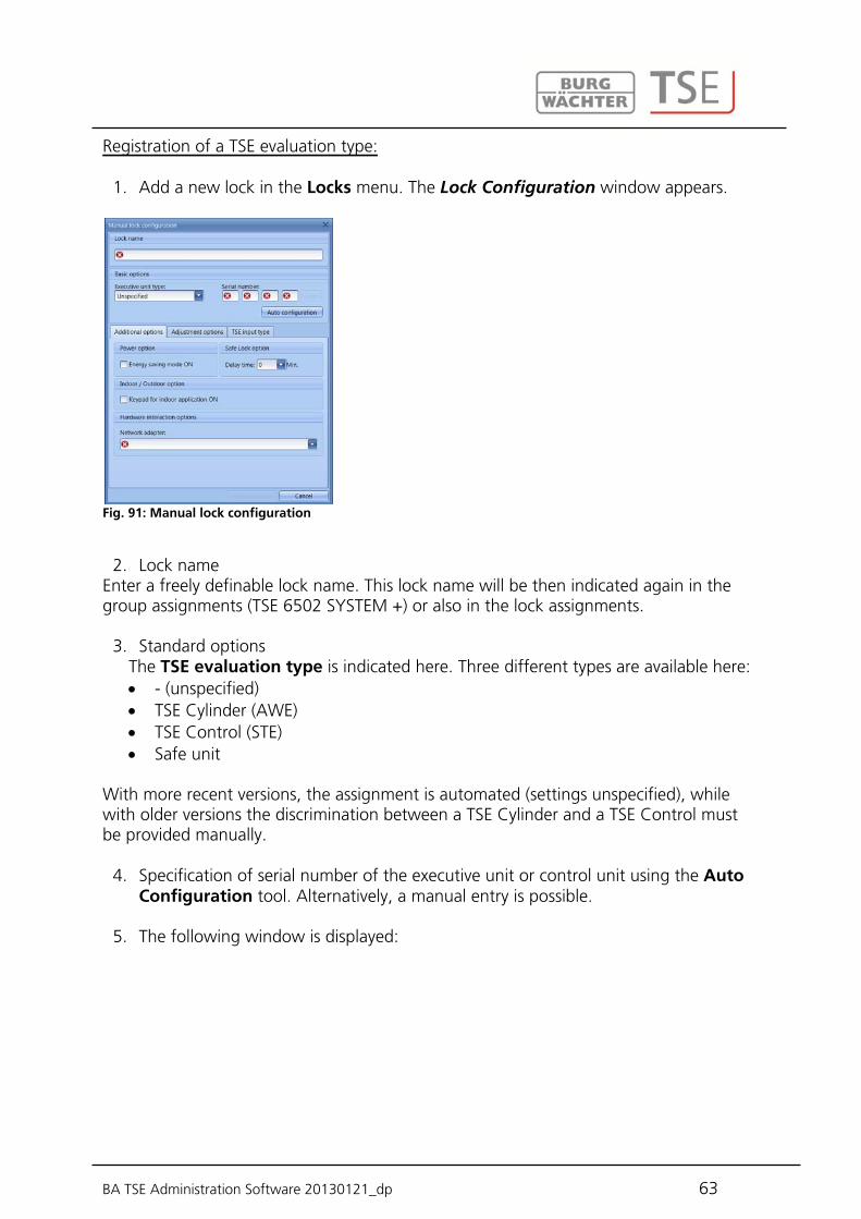
Registration of a TSE evaluation type:
1. Add a new lock in the Locks menu. The Lock Configuration window appears.
Fig. 91: Manual lock configuration
2. Lock name
Enter a freely definable lock name. This lock name will be then indicated again in the group assignments (TSE 6502 SYSTEM +) or also in the lock assignments.
3. Standard options The TSE evaluation type is indicated here. Three different types are available here: - (unspecified) TSE Cylinder (AWE) TSE Control (STE) Safe unit
With more recent versions, the assignment is automated (settings unspecified), while with older versions the discrimination between a TSE Cylinder and a TSE Control must be provided manually.
4. Specification of serial number of the executive unit or control unit using the Auto Configuration tool. Alternatively, a manual entry is possible.
5. The following window is displayed:
BA TSE Administration Software 20130121_dp 64
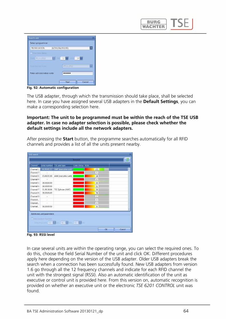
Fig. 92: Automatic configuration
The USB adapter, through which the transmission should take place, shall be selected here. In case you have assigned several USB adapters in the Default Settings, you can make a corresponding selection here. Important: The unit to be programmed must be within the reach of the TSE USB adapter. In case no adapter selection is possible, please check whether the default settings include all the network adapters. After pressing the Start button, the programme searches automatically for all RFID channels and provides a list of all the units present nearby.
Fig. 93: RSSI level
In case several units are within the operating range, you can select the required ones. To do this, choose the field Serial Number of the unit and click OK. Different procedures apply here depending on the version of the USB adapter. Older USB adapters break the search when a connection has been successfully found. New USB adapters from version 1.6 go through all the 12 frequency channels and indicate for each RFID channel the unit with the strongest signal (RSSI). Also an automatic identification of the unit as executive or control unit is provided here. From this version on, automatic recognition is provided on whether an executive unit or the electronic TSE 6201 CONTROL unit was found.

BA TSE Administration Software 20130121_dp 65
The RFID channels are indicated in the Channel column. This window shows all the units located within the operating range, disregarding the validity of the administrator code. In case the administrator code is not valid, an invalid number is displayed in the Serial Number column (00:00:00:00). If 2 units are superimposed on a single RFID channel, the serial number with the highest signal strength (RSSI) is displayed. This is then the unit that will be addressed when wireless transmission takes place. If a wrong unit is addressed, the USB adapter should be brought closer to the unit to be registered. If this still does not lead to the desired result, remove the batteries from the wrongly responding unit temporarily during the registration process. The Code column indicates the status of recognition of the administrator code (green = password OK; red = password incorrect). In this example, five units respond, out of which three have the appropriate administrator code. The unit with the highest RSSI value is automatically preselected. If you wish to select another unit, you have to do so by double-clicking the corresponding Serial Number field. Apart from this, TSE 6102 FS + keypads from version 4.9 + any TSE keypad from version 6, as well as a TSE 6106 CARD READER can be assigned to an executive or control unit. Attention: A fingerprint can be loaded through the software only when a keypad has been registered using this menu item. The preceding section described the ways of assigning the executive or control unit. This section will show how to assign a TSE keypad or a TSE card reader to these units. This is necessary for instance for transferring fingerprints using the software.
Registering a TSE input type: 1. Under TSE Input Type, choose the tab Unit Search

BA TSE Administration Software 20130121_dp 66
Fig. 94: Unit search
2. Choose the unit type you wish to register. The following window appears:
Fig. 95: Programming
The USB adapter shall be selected here, through which the transmission should take place. In case you have assigned several USB adapters in the Default Settings, you can make a corresponding selection here. Important: The unit to be programmed must be within the reach of the TSE USB adapter. In case no adapter selection is possible, please check whether the default settings include all the network adapters. 3. Choose the Start button. The programme searches automatically for all RFID
channels and provides a list of all the units present nearby.

BA TSE Administration Software 20130121_dp 67
Abb. 96: Unit search
In case several units are within the operating range, you can select the required ones. To do this, choose the field Serial Number of the unit and click OK. The RFID channels are indicated in the Channel column. This window shows all the units located within the operating range, disregarding the validity of the administrator code. In case the administrator code is not valid, an invalid number is displayed in the Serial Number column (00:00:00:00). If 2 units are superimposed on a single RFID channel, the serial number with the highest signal strength (RSSI) is displayed. This is then the unit that will be addressed when wireless transmission takes place. If a wrong unit is addressed, the USB adapter should be brought closer to the unit to be registered. If this still does not lead to the desired result, remove the batteries from the wrongly responding unit temporarily during the registration process. The Code column indicates the status of recognition of the administrator code (green = password OK; red = password incorrect). In this example, five units respond, out of which three have the appropriate administrator code. The unit with the highest RSSI value is automatically preselected. If you wish to select another unit, you have to do so by double-clicking the corresponding Serial Number field. The Lock Configuration window appears.

BA TSE Administration Software 20130121_dp 68
Fig. 97: Lock configuration
4. Choose Apply Changes in order to save the data and return to lock configuration.
Fig. 98: Lock administration
Additional tabs are active in the lock configuration window: Additional options
Power options If the Energy option of the TSE is checked, the lifecycle of the battery operated unit is extended, while the operating range of the E-KEY is reduced. All the units of a safe system should be provided with equal energy options. When a network unit is used, the energy saving mode should be deactivated.
An opening delay can be specified when a safe lock is being adjusted. The specified value indicates the opening delay in minutes (max. 99 min).
BA TSE Administration Software 20130121_dp 69
If you have selected a TSE Control associated with the TSE evaluation type, you can activate the timer assigned under the TSE Control Timer menu item here. In addition, you can enter a switching time or set it to the random function.
Hardware options Selection of the USB adapter for data transmission
Configuration options (for TSE Control units)
Selection of TSE Control timer Switching time for TSE Control
TSE input type
Add units Manual registration of a new input type
Search for units Automatic registration of an input type
Change input type Delete unit
Press Apply Changes to save the settings The bottom part of the window provides for:
Importing another client based on the locks or exporting the data in the CSV format
Editing the existing locks by automatic or manual configuration Adding locks Deleting locks
When completed, the specifications have to be saved.

BA TSE Administration Software 20130121_dp 70
(for TSE 6502 Software SYSTEM + only) Use the Groups tool to specify group names and assign groups to locks.
Fig. 99: Groups
Proceed as follows: Select a group by double-clicking it and
edit the preset group Select the locks to which the group should be granted access. When you select
the rectangle at the lock name, all the groups will be authorised to open the corresponding lock.
Apart from this, you can delete groups or, as long as you have not selected the maximum number of 50 groups, create new groups.
In addition, you can use the button to import or export the data in the CSV format or to print them. All the entries have to be saved.
8.3.3 Groups

BA TSE Administration Software 20130121_dp 71
The entire communication between the software and the units is performed within the Data Transmission menu item. Apart from this, the administrator code can be changed here and the history of all or individual units can be indicated.
Fig. 100: Data transmission
The entry of the administrator code is necessary for all data transmission functions. This code is factory-set to 123456. With all the TSE 6000 SYSTEM units, the administrator code is provided together with the SNA serial number on a separate tag attached to the executive unit. The window shows all the units defined under the Locks menu. To provide a better overview, all the units, which are currently not active, are marked with red.
The software automatically verifies whether the number of the selected users is allowed with the corresponding opening medium for the particular lock. This has a particular importance when safe electronics is programmed. In such case, a maximum number of 9 pin code users and one administrator (with a pin code), as well as 299 TSE 6103 E-KEYs can be transferred to the lock. In case the number of users in terms of the maximum number per lock is exceeded, an error message is created and no data transmission is possible any more. In such case, the number of users has to be correspondingly corrected in the Users menu.
When fingerscan data are transferred to a TSE unit, the software automatically identifies whether a single executive unit or a combination of an executive unit and a keypad are available. The assignment must be made within the Locks menu! Programming of fingerscan data can be made only when both the executive unit and the keypad can be wirelessly programmed with the corresponding data.
Attention: Data transmission overwrites completely the existing data record.
8.4 Data transmission

BA TSE Administration Software 20130121_dp 72
Any changes programmed manually in the lock will be overwritten!
If you have not read the history when programming, the events that occurred up to the moment of new programming are no more available.
To transmit the data, proceed as follows:
Choose the Programming button. You can then choose between o Programming the selected lock o Programming all the selected locks
All the locks can be selected by activating them in the Programming column.
Decide whether the history of the locks to be programmed should be transferred to the PC and stored there.
In any case, the window for the beginning of programming is displayed
Fig. 101: Programming
Choose the programming adapter for the locks to be programmed here, or choose the option Use adapters from lock parameters in order to address different USB adapters.
In addition, the date and time on which the lock updating begins can be specified (delayed programming). Important! The computer system must be active in order to use delayed programming!
If you have confirmed the history indication of the lock, you can determine the date on which the history starts. This date will then apply to all the locks if you wish to program more than one.
Entry of administrator code To start the data transmission, choose the Start button. The individual software types have different properties related to data transmission:
8.4.1 Transmission of data

BA TSE Administration Software 20130121_dp 73
With the TSE 6501 SYSTEM and 6502 SYSTEM + versions, the following window appears, in which all the units to be programmed are listed and the progress of transmission indicated. At the same time, the data are verified and an error message displayed if e.g. the number of users for a lock is too high, or if the data transmission for individual locks is incorrect.
Fig. 102: Programming: indication of progress
The programming status is indicated in the Transmission Status column. Together with this information, also the weakest battery status of the programmed unit is displayed. However, at this point, it is not possible to distinguish between an input unit and an executive unit. In addition, a transmission indicator is displayed. Two curves are indicated here. Together, these curves and the indicated values provide information on the quality of transmission. Based on this, en error analysis can be made for the transmission and, as the case may be, corrective measures implemented. The blue curve describes the wireless level, showing the absolute value of the field strength. Ideally, this value should be between 40 and 80. If the value is smaller, the reach is too high for the particular transmission. In such case, reduce the reach for data transmission! The red curve describes the quality level of the signal. This allows for a conclusion on whether other transmitters are creating signals in the same RFID channel, or whether the noise level in the particular channel is too high. The value should ideally be between 90 and 120 in order to provide for a smooth wireless connection. If the value is smaller, please change the RFID channel. The Status Details tab can be used to issue the error messages in plain text. After a successful programming, use the Ok button to close the window.

BA TSE Administration Software 20130121_dp 74
With the TSE 5500 Software LIGHT, the following window appears:
Fig. 103: Data transmission - 1 TSE 5500 LIGHT
The individual RFID channels are now enquired when data transmission takes place.
Fig. 104: Data transmission - 2 TSE 5500 LIGHT
The programming status is indicated in the Transmission Status column. After a successful programming, the transmitted lock data turn to green. Together with this information, also the weakest battery status of the programmed unit is displayed. However, at this point, it is not possible to distinguish between an input unit and an executive unit. After a successful programming, use the Ok button to close the window.
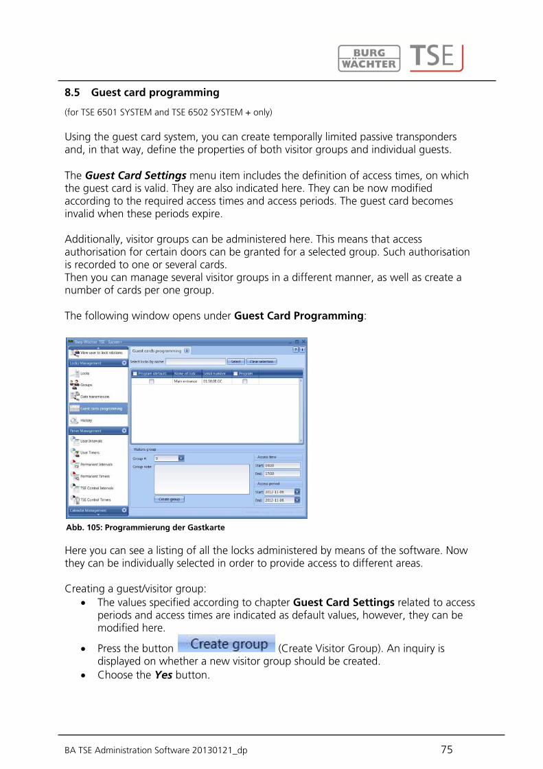
BA TSE Administration Software 20130121_dp 75
(for TSE 6501 SYSTEM and TSE 6502 SYSTEM + only) Using the guest card system, you can create temporally limited passive transponders and, in that way, define the properties of both visitor groups and individual guests. The Guest Card Settings menu item includes the definition of access times, on which the guest card is valid. They are also indicated here. They can be now modified according to the required access times and access periods. The guest card becomes invalid when these periods expire. Additionally, visitor groups can be administered here. This means that access authorisation for certain doors can be granted for a selected group. Such authorisation is recorded to one or several cards. Then you can manage several visitor groups in a different manner, as well as create a number of cards per one group. The following window opens under Guest Card Programming:
Here you can see a listing of all the locks administered by means of the software. Now they can be individually selected in order to provide access to different areas. Creating a guest/visitor group:
The values specified according to chapter Guest Card Settings related to access periods and access times are indicated as default values, however, they can be modified here.
Press the button (Create Visitor Group). An inquiry is displayed on whether a new visitor group should be created.
Choose the Yes button.
8.5 Guest card programming
Abb. 105: Programmierung der Gastkarte
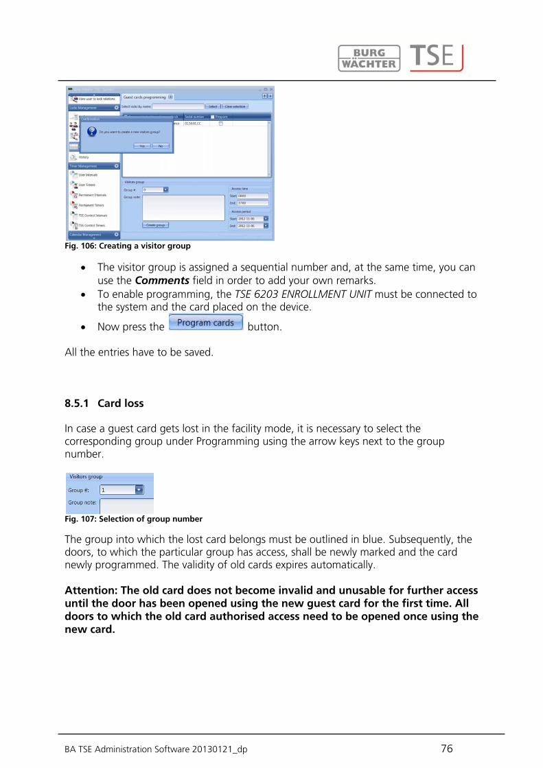
BA TSE Administration Software 20130121_dp 76
Fig. 106: Creating a visitor group
The visitor group is assigned a sequential number and, at the same time, you can use the Comments field in order to add your own remarks.
To enable programming, the TSE 6203 ENROLLMENT UNIT must be connected to the system and the card placed on the device.
Now press the button.
All the entries have to be saved.
In case a guest card gets lost in the facility mode, it is necessary to select the corresponding group under Programming using the arrow keys next to the group number.
Fig. 107: Selection of group number
The group into which the lost card belongs must be outlined in blue. Subsequently, the doors, to which the particular group has access, shall be newly marked and the card newly programmed. The validity of old cards expires automatically. Attention: The old card does not become invalid and unusable for further access until the door has been opened using the new guest card for the first time. All doors to which the old card authorised access need to be opened once using the new card.
8.5.1 Card loss
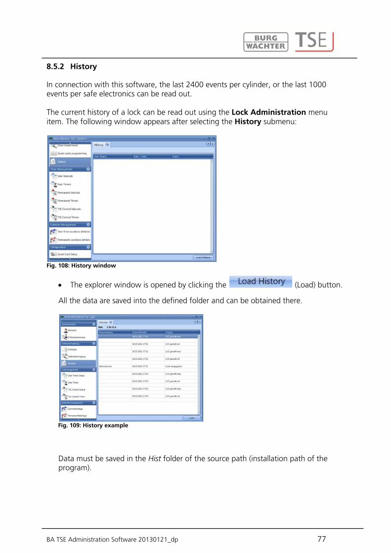
BA TSE Administration Software 20130121_dp 77
In connection with this software, the last 2400 events per cylinder, or the last 1000 events per safe electronics can be read out. The current history of a lock can be read out using the Lock Administration menu item. The following window appears after selecting the History submenu:
Fig. 108: History window
The explorer window is opened by clicking the (Load) button.
All the data are saved into the defined folder and can be obtained there.
Fig. 109: History example
Data must be saved in the Hist folder of the source path (installation path of the program).
8.5.2 History
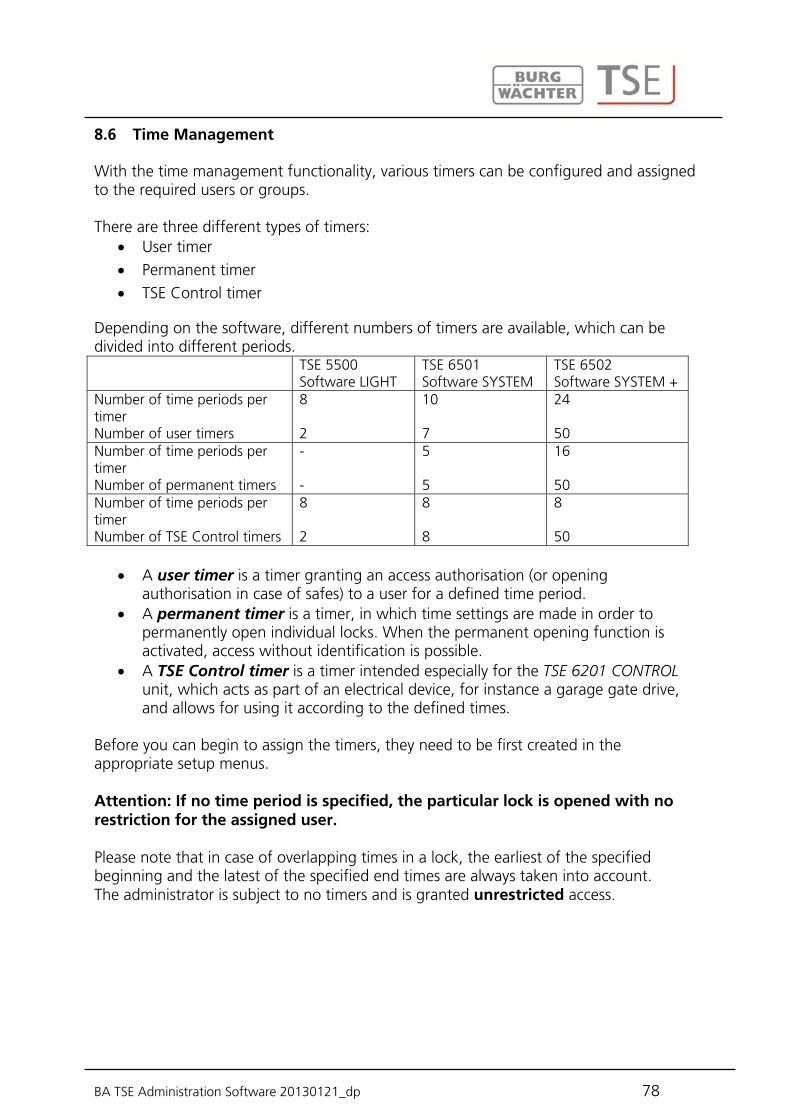
BA TSE Administration Software 20130121_dp 78
With the time management functionality, various timers can be configured and assigned to the required users or groups. There are three different types of timers:
User timer Permanent timer TSE Control timer
Depending on the software, different numbers of timers are available, which can be divided into different periods. TSE 5500
Software LIGHT TSE 6501 Software SYSTEM
TSE 6502 Software SYSTEM +
Number of time periods per timer Number of user timers
8 2
10 7
24 50
Number of time periods per timer Number of permanent timers
- -
5 5
16 50
Number of time periods per timer Number of TSE Control timers
8 2
8 8
8 50
A user timer is a timer granting an access authorisation (or opening
authorisation in case of safes) to a user for a defined time period. A permanent timer is a timer, in which time settings are made in order to
permanently open individual locks. When the permanent opening function is activated, access without identification is possible.
A TSE Control timer is a timer intended especially for the TSE 6201 CONTROL unit, which acts as part of an electrical device, for instance a garage gate drive, and allows for using it according to the defined times.
Before you can begin to assign the timers, they need to be first created in the appropriate setup menus. Attention: If no time period is specified, the particular lock is opened with no restriction for the assigned user. Please note that in case of overlapping times in a lock, the earliest of the specified beginning and the latest of the specified end times are always taken into account. The administrator is subject to no timers and is granted unrestricted access.
8.6 Time Management

BA TSE Administration Software 20130121_dp 79
When the user timer setup is selected, the following window appears (differently according to the different numbers of timers):
Fig. 110: User timer setup (TSE 5500 LIGHT and TSE 6502 SYSTEM +)
The particular access and opening rights for defined areas are combined with the dates and time periods here. These access and opening authorisations are then assigned to particular timers under User Timers. Individual access or opening authorisations can be granted by double-clicking the corresponding Date (Tag) or Time (Zeit) sections. In the Date column, individual days or periods can be specified. The Time column provides for specification of times of the day. 8 time periods are available with the TSE 5500 Software LIGHT. The first 4 time periods under the user timer are assigned to the timer 1, the last 4 time periods to the timer 2. Please create the time periods in compliance with this. The settings determined here indicate the time period, during which an access authorisation is valid. Please note that in case of overlapping times in a lock, the earliest of the specified beginning and the latest of the specified end times are always taken into account.
The time periods determined under User Timer Setup are assigned to the individual timers here. The first eight time periods can be used for the purpose of guest card applications with the TSE 6501 Software SYSTEM and TSE 6502 Software SYSTEM +. This column is omitted with the TSE 5500 Software LIGHT.
8.6.1 User timer setup
8.6.2 User timer

BA TSE Administration Software 20130121_dp 80
The following window is displayed, in which all the time periods are indicated as created in the User Timer Setup menu:
Fig. 111: User timer - TSE 6502 SYSTEM + and TSE 5500 LIGHT
The individual timers are added to the list using the Add Timer button. The restricted time periods, during which they are active, are then assigned to these timers as defined in the setup. An activation check is used for this purpose.
The initial 8 time periods can be additionally used for guest cards. This option is described in detail under the Guest Card Settings menu. If a timer record exists within the list, additional buttons become active in the lower bar, using which the timers can be renamed, deleted and saved when the settings are
complete.
In addition, you can use the button to import or export the data in the CSV format or to print them.
(TSE 6501 SYSTEM and TSE 6502 SYSTEM + only) The programming is done in the same way as described in chapter User timer setup. As opposed to user timers, permanent timers are assigned to locks (compare to the chapter Locks). The permanent opening function identifies the related timers. This can be explained in
8.6.3 Permanent timer setup

BA TSE Administration Software 20130121_dp 81
the following example: Monday - Friday Start: 02:00pm End: 04:00pm Monday - Friday Start: 04:00pm End: 06:00pm If the user opens the locking system permanently on Tuesday at 03:33pm, the opening time will be till 06:00pm (inclusively). In the following example, also a midnight transition can be provided: Monday - Friday Start: 10:00pm End: 11:59pm Monday - Friday Start: 00:00am End: 06:00am Users or groups assigned appropriately to these timers are authorised within these time periods. The following window appears after selecting the User Timer Setup:
Fig. 112: Permanent timer setup
The particular access and opening rights for defined areas are combined with the dates and time periods here. These access and opening authorisations are then assigned to particular timers under Permanent Timers. Individual access or opening authorisations can be granted by double-clicking the corresponding Date or Time sections. In the Date column, individual days or time periods can be specified. The Time column provides for specification of times of the day. The settings determined here indicate the time period, during which an access authorisation is valid.
(TSE 6501 SYSTEM and TSE 6502 SYSTEM + only) The time periods determined under Permanent Timer Setup are assigned to the individual timers here. The following window appears after selection, in which all the time periods are indicated:
8.6.4 Permanent timer
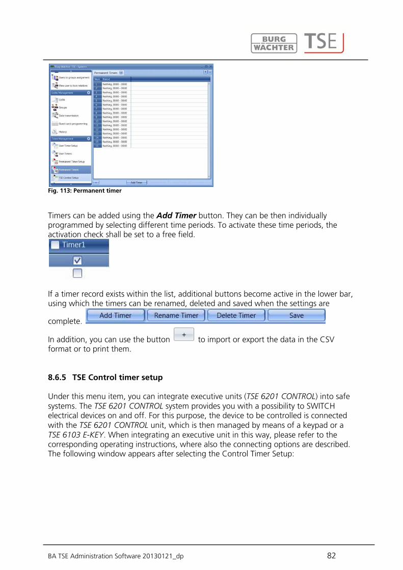
BA TSE Administration Software 20130121_dp 82
Fig. 113: Permanent timer
Timers can be added using the Add Timer button. They can be then individually programmed by selecting different time periods. To activate these time periods, the activation check shall be set to a free field.
If a timer record exists within the list, additional buttons become active in the lower bar, using which the timers can be renamed, deleted and saved when the settings are
complete.
In addition, you can use the button to import or export the data in the CSV format or to print them.
Under this menu item, you can integrate executive units (TSE 6201 CONTROL) into safe systems. The TSE 6201 CONTROL system provides you with a possibility to SWITCH electrical devices on and off. For this purpose, the device to be controlled is connected with the TSE 6201 CONTROL unit, which is then managed by means of a keypad or a TSE 6103 E-KEY. When integrating an executive unit in this way, please refer to the corresponding operating instructions, where also the connecting options are described. The following window appears after selecting the Control Timer Setup:
8.6.5 TSE Control timer setup
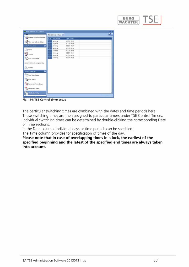
BA TSE Administration Software 20130121_dp 83
Fig. 114: TSE Control timer setup
The particular switching times are combined with the dates and time periods here. These switching times are then assigned to particular timers under TSE Control Timers. Individual switching times can be determined by double-clicking the corresponding Date or Time sections. In the Date column, individual days or time periods can be specified. The Time column provides for specification of times of the day. Please note that in case of overlapping times in a lock, the earliest of the specified beginning and the latest of the specified end times are always taken into account.

BA TSE Administration Software 20130121_dp 84
The time periods determined under TSE Control Timer Setup are assigned to the individual timers here. The following window appears after selection, in which all the time periods are indicated:
Fig. 115: TSE Control timer
Timers can be added using the Add Timer button. They can be then individually programmed by selecting different time periods. To activate these time periods, the activation check shall be set to a free field.
If a timer record exists within the list, additional buttons become active in the lower bar, using which the timers can be renamed, deleted and saved when the settings are
complete.
In addition, you can use the button to import or export the data in the CSV format or to print them.
8.6.6 TSE Control timer
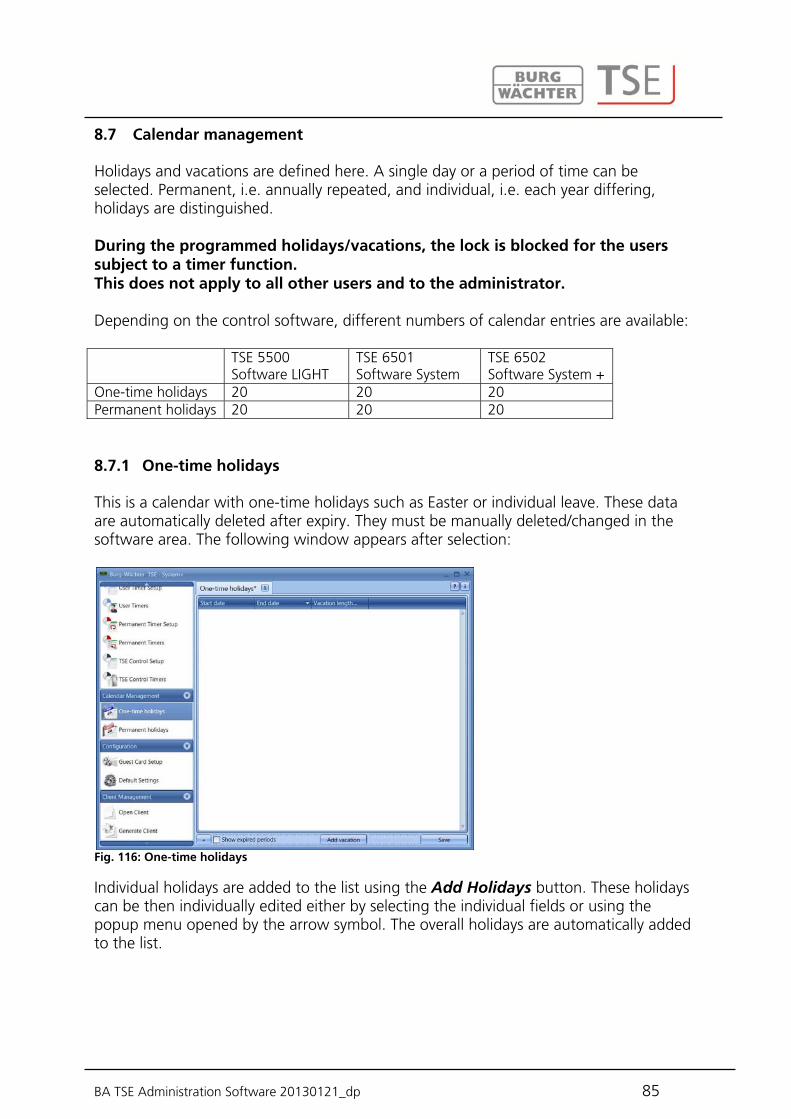
BA TSE Administration Software 20130121_dp 85
Holidays and vacations are defined here. A single day or a period of time can be selected. Permanent, i.e. annually repeated, and individual, i.e. each year differing, holidays are distinguished. During the programmed holidays/vacations, the lock is blocked for the users subject to a timer function. This does not apply to all other users and to the administrator. Depending on the control software, different numbers of calendar entries are available: TSE 5500
Software LIGHT TSE 6501 Software System
TSE 6502 Software System +
One-time holidays 20 20 20 Permanent holidays 20 20 20
This is a calendar with one-time holidays such as Easter or individual leave. These data are automatically deleted after expiry. They must be manually deleted/changed in the software area. The following window appears after selection:
Fig. 116: One-time holidays
Individual holidays are added to the list using the Add Holidays button. These holidays can be then individually edited either by selecting the individual fields or using the popup menu opened by the arrow symbol. The overall holidays are automatically added to the list.
8.7 Calendar management
8.7.1 One-time holidays

BA TSE Administration Software 20130121_dp 86
Fig. 117: Calendar
If a record exists within the list, additional buttons become active in the lower bar, using which the records can be deleted and saved when the settings are complete. Expired holidays are no more indicated in the list, however, they can be recalled and made visible using the Expired Holidays button.
In addition, you can use the button to print the data in the CSV format.
Permanent holidays are fixed to a certain date, such as New Year or Christmas. They are transferred to all subsequent years and do not need to be programmed again. The following window appears after selection:
Fig. 118: Permanent holidays
Individual holidays are added to the list using the Add Holidays button. These holidays can be then individually edited either by selecting the individual fields or using the popup menu opened by the arrow symbol. The overall holidays are automatically added to the list.
8.7.2 Permanent holidays
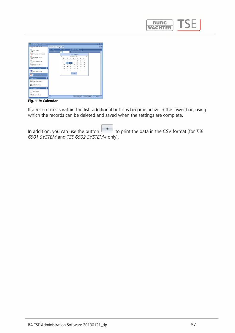
BA TSE Administration Software 20130121_dp 87
Fig. 119: Calendar
If a record exists within the list, additional buttons become active in the lower bar, using which the records can be deleted and saved when the settings are complete.
In addition, you can use the button to print the data in the CSV format (for TSE 6501 SYSTEM and TSE 6502 SYSTEM+ only).

BA TSE Administration Software 20130121_dp 88
9 Programming of safe electronics
Many administration software systems can be used, in addition to managing the access doors, also to manage safe electronics (safes with appropriate lock electronics by BURG-WÄCHTER). Different conditions apply to this administration, which are described in detail in this chapter or at the corresponding points in the software. Please read also the operating manuals for TRSE 6000 and TRSE 6000 FS for products by BURG-WÄCHTER in this respect. Attention: In case of administration of safe electronics using the software, the data must be stored on a removable data carrier. Saving of the data on a computer is not admissible and is therefore not allowed by the system. If the safe electronics data is administered using the software with the programme not starting from a removable data carrier, the following error message is displayed:
Fig. 120: Prompt on removable data carrier
Start the programme from a removable data carrier. The removable data carrier should be stored at a safe place (e.g. a safe) after the programming. Please note that the software links to the desktop or the Start menu do not exist any more after the copying to the removable data carrier, however, they can be created manually when required. Besides programming of access authorisations, also an opening delay can be provided from version 4.3 of the software. The opening delay is the time that needs to elapse after the 1st input of the opening code, before it can be input repeatedly. The opening delay is defined within lock administration, specifically in lock configuration.
After selecting one of the buttons , the lock configuration window appears. Please find the detailed function description in chapter Locks. The additional options include the safe lock options:

BA TSE Administration Software 20130121_dp 89
Fig. 121: Lock configuration
The delay can be set to up to 99 minutes. In order to enhance the protection against intrusion, the following points should be observed: For locking systems with material code carriers, e.g. a TSE 6103 E-KEY:
The code carrier should be consistently stored safely, so that it is accessible only to the authorised persons.
In case of a loss of the code carrier, the lock should be immediately replaced or converted to a new combination by changing the coding, and/or the code of the lost code carrier should be blocked/ deleted.
For locking systems requiring a code: No personal data (e.g. dates of birth) or other data, for which a link can be
derived to the code owner, should be used for coding. If the code is stored in writing, such document should be consistently stored
safely, so that it is accessible only to the authorised persons.
Attention: Any changes of the administrator code and of the user codes shall be made with the safe door opened. When the locking system has been reset to another code, this new code should be repeatedly used with the safe door opened. Please note that the number of users in the safe electronics is restricted to 9 pin code users and one administrator on account of the lock security class. Besides this, up to 299 TSE 6103 E-KEYs can be registered per unit. Attention: No transfer of fingerprint data to safe electronics is possible. The fingerprint data must be saved in the lock electronics manually!
BA TSE Administration Software 20130121_dp 90
When programming fingerscan safe electronics, the following shall be born in mind:
At least two opening codes shall be entered to open the safe using fingerprint; another opening code must be entered in addition to fingerscan. This can be either another fingerscan, but also a pin code or an additional TSE 6103 E-KEY.
All the fingerscans are stored in the system with a value of ½. In order to acquire the authorisation to open, a value of at least 1 must be achieved. A pin code for the opening must therefore be entered with a value of at least ½. Possible is also opening with an additional fingerscan (a total value of 1). Please read the corresponding chapter on setting the values (rights).
For safe electronics versions V1.1 and lower, the right FS+ must be selected in the rights management of the software. This applies to the pin code, as well as to the TSE 6103 E-KEY. In data transmission, an error message is generated when the number of users is exceeded. In such case, the assignment of users for safe electronics shall be adjusted in the user administration menu. No data transmission is possible without such adjustment.

BA TSE Administration Software 20130121_dp 91
BURG-WÄCHTER KG Altenhofer Weg 15 58300 Wetter Germany [email protected] www.burg-waechter.biz
Mistakes and changes reserved.


