184
TSQ Series TSQ Quantum XLS and TSQ Quantum GC User Guide 70111-97220 Revision B May 2010

TSQ Series
TSQ Quantum XLS and TSQ Quantum GCUser Guide
70111-97220 Revision B May 2010
© 2010 Thermo Fisher Scientific Inc. All rights reserved.
TriPlus is a trademark and TSQ Quantum, TSQ Quantum XLS, TSQ Quantum GC, and TRACE GC Ultra are registered trademarks of Thermo Fisher Scientific Inc. in the United States.
The following are registered trademarks in the United States and other countries: Swagelok is a registered trademark of the Crawford Fitting Company. Dranetz is a registered trademark of Dranetz Technologies, Inc. Styrofoam is a registered trademark of Dow Chemical Company. Teflon is a registered trademark of E. I. du Pont de Nemours & Co. Convectron is a registered trademark of Helix Technology Corporation. Intel, Pentium, Xeon, and Core are registered trademarks of Intel Corporation. All other trademarks are the property of Thermo Fisher Scientific and its subsidiaries.
Thermo Fisher Scientific Inc. provides this document to its customers with a product purchase to use in the product operation. This document is copyright protected and any reproduction of the whole or any part of this document is strictly prohibited, except with the written authorization of Thermo Fisher Scientific Inc.
The contents of this document are subject to change without notice. All technical information in this document is for reference purposes only. System configurations and specifications in this document supersede all previous information received by the purchaser.
Thermo Fisher Scientific Inc. makes no representations that this document is complete, accurate or error-free and assumes no responsibility and will not be liable for any errors, omissions, damage or loss that might result from any use of this document, even if the information in the document is followed properly.
This document is not part of any sales contract between Thermo Fisher Scientific Inc. and a purchaser. This document shall in no way govern or modify any Terms and Conditions of Sale, which Terms and Conditions of Sale shall govern all conflicting information between the two documents.
Release history: Revision A March 2010; Revision B May 2010
Software version: Xcalibur 2.1, Thermo Foundation 1.0, TSQ 2.3
For Research Use Only. Not for use in diagnostic procedures.

Regulatory Compliance
Thermo Fisher Scientific performs complete testing and evaluation of its products to ensure full compliance with applicable domestic and international regulations. When the system is delivered to you, it meets all pertinent electromagnetic compatibility (EMC) and safety standards as described in the next section or sections by product name.
Changes that you make to your system may void compliance with one or more of these EMC and safety standards. Changes to your system include replacing a part or adding components, options, or peripherals not specifically authorized and qualified by Thermo Fisher Scientific. To ensure continued compliance with EMC and safety standards, replacement parts and additional components, options, and peripherals must be ordered from Thermo Fisher Scientific or one of its authorized representatives.
TSQ Quantum XLS
EMC Directive 2004/108/EC EMC compliance has been evaluated by TUV Rheinland of North America Inc.
Low Voltage Directive 2006/95/EC
This device complies with Low Voltage Directive 2006/95/EC and harmonized standards: EN 61010-1: 2001; IEC 61010-1: 2002; UL 61010A-1: 2004; CAN/CSA 22.2 61010-1: 2004.
TSQ Quantum GC
EMC Directive 2004/108/EC EMC compliance has been evaluated by TUV Rheinland of North America Inc.
EN 55011 2007; A2: 2007 EN 61000-4-5 2005
EN 61000-3-2 2006 EN 61000-4-6 2007
EN 61000-3-3 1995; A1: 2001; A2: 2005 EN 61000-4-11 2004
EN 61000-4-2 1995; A1: 1999; A2: 2001 EN 61326-1 2006
EN 61000-4-3 2006 FCC Class A 2008, CFR 47, Part 15
EN 61000-4-4 2004
EN 55011 1998, 1999, 2002 EN 61000-4-3 2002
EN 61000-3-2 1995, A1; 1998, A2; 1998, A14; 2000
EN 61000-4-4 1995, A1; 2000, A2; 2001

Low Voltage Safety ComplianceCompliance with safety issues is declared under Thermo Fisher Scientific sole responsibility.This device complies with Low Voltage Directive 2006/95/EC and harmonized standard EN 61010-1:2001.
Changes that you make to your system may void compliance with one or more of these EMC and safety standards. Changes to your system include replacing a part or adding components, options, or peripherals not specifically authorized and qualified by Thermo Fisher Scientific. To ensure continued compliance with EMC and safety standards, replacement parts and additional components, options, and peripherals must be ordered from Thermo Fisher Scientific or one of its authorized representatives.
FCC Compliance Statement
Notice on Lifting and Handling ofThermo Fisher Scientific Instruments
For your safety, and in compliance with international regulations, the physical handling of this Thermo Fisher Scientific instrument requires a team effort to lift and/or move the instrument. This instrument is too heavy and/or bulky for one person alone to handle safely.
EN 61000-3-3 1998, 2001 EN 61000-4-5 1995, A1; 2001
EN 61326-1 1998, 2001, 2003 EN 61000-4-6 1996, A1; 2003
EN 61000-4-2 2001 EN 61000-4-11 1994, A1; 2001
CISPR 11 1998; 1999; 2002
FCC Class A, CFR 47 Part 15: 2007
THIS DEVICE COMPLIES WITH PART 15 OF THE FCC RULES. OPERATION IS SUBJECT TO THE FOLLOWING TWO CONDITIONS: (1) THIS DEVICE MAY NOT CAUSE HARMFUL INTERFERENCE, AND (2) THIS DEVICE MUST ACCEPT ANY INTERFERENCE RECEIVED, INCLUDING INTERFERENCE THAT MAY CAUSE UNDESIRED OPERATION.
CAUTION Read and understand the various precautionary notes, signs, and symbols contained inside this manual pertaining to the safe use and operation of this product before using the device.

WEEE Compliance
This product is required to comply with the European Union’s Waste Electrical & Electronic Equipment (WEEE) Directive 2002/96/EC. It is marked with the following symbol:
Thermo Fisher Scientific has contracted with one or more recycling or disposal companies in each European Union (EU) Member State, and these companies should dispose of or recycle this product. See www.thermo.com/WEEERoHS for further information on Thermo Fisher Scientific’s compliance with these Directives and the recyclers in your country.
WEEE Konformität
Dieses Produkt muss die EU Waste Electrical & Electronic Equipment (WEEE) Richtlinie 2002/96/EC erfüllen. Das Produkt ist durch folgendes Symbol gekennzeichnet:
Thermo Fisher Scientific hat Vereinbarungen mit Verwertungs-/Entsorgungsfirmen in allen EU-Mitgliedsstaaten getroffen, damit dieses Produkt durch diese Firmen wiederverwertet oder entsorgt werden kann. Mehr Information über die Einhaltung dieser Anweisungen durch Thermo Fisher Scientific, über die Verwerter, und weitere Hinweise, die nützlich sind, um die Produkte zu identifizieren, die unter diese RoHS Anweisung fallen, finden sie unter www.thermo.com/WEEERoHS.

Conformité DEEE
Ce produit doit être conforme à la directive européenne (2002/96/EC) des Déchets d'Equipements Electriques et Electroniques (DEEE). Il est marqué par le symbole suivant:
Thermo Fisher Scientific s'est associé avec une ou plusieurs compagnies de recyclage dans chaque état membre de l’union européenne et ce produit devrait être collecté ou recyclé par celles-ci. Davantage d'informations sur la conformité de Thermo Fisher Scientific à ces directives, les recycleurs dans votre pays et les informations sur les produits Thermo Fisher Scientific qui peuvent aider la détection des substances sujettes à la directive RoHS sont disponibles sur www.thermo.com/WEEERoHS.

AVVERTENZA
trumento s de ntes de
al arse y limentacion nto sin sus o remueva
s tarjetas
Shock da folgorazione. L’apparecchio è alimentato da corrente ad alta tensione che puo provocare lesioni fisiche. Prima di effettuare qualsiasi intervento di manutenzione occorre spegnere ed isolare l’apparecchio dalla linea elettrica. Non attivare lo strumento senza lo schermo superiore. Non togliere i coperchi a protezione dalle schede di circuito stampato (PCB).
e contener . Utilice quimicos nos o cipientes y a
Prodotti chimici. Possibile presenza di sostanze chimiche pericolose nell’apparecchio. Indossare dei guanti per maneggiare prodotti chimici tossici, cancerogeni, mutageni, o corrosivi/irritanti. Utilizzare contenitori aprovo e seguire la procedura indicata per lo smaltimento dei residui di olio.
que lop de efectuar
Calore. Attendere che i componenti riscaldati si raffreddino prima di effetturare l’intervento di manutenzione.
ar el
Incendio. Adottare le dovute precauzioni quando si usa il sistema in presenza di gas infiammabili.
icaduras de s que usar teojos tos .
Pericolo per la vista. Gli schizzi di prodotti chimici o delle particelle presenti nell’aria potrebbero causare danni alla vista. Indossare occhiali protettivi quando si maneggiano prodotti chimici o si effettuano interventi di manutenzione sull’apparecchio.
e existe un gorias én se utiliza l usuario a n este
Pericolo generico. Pericolo non compreso tra le precedenti categorie. Questo simbolo è utilizzato inoltre sull’apparecchio per segnalare all’utente di consultare le istruzioni descritte nel presente manuale.
de un tes de o con la local para r Scientific
Quando e in dubbio la misura di sicurezza per una procedura, prima di continuare, si prega di mettersi in contatto con il Servizio di Assistenza Tecnica locale per i prodotti di Thermo Fisher Scientific San Jose.
CAUTION Symbol CAUTION VORSICHT ATTENTION PRECAUCION
Electric Shock: This instrument uses high voltages that can cause personal injury. Before servicing, shut down the instrument and disconnect the instrument from line power. Keep the top cover on while operating the instrument. Do not remove protective covers from PCBs.
Elektroschock: In diesem Gerät werden Hochspannungen verwendet, die Verletzungen verursachen können. Vor Wartungsarbeiten muß das Gerät abgeschaltet und vom Netz getrennt werden. Betreiben Sie Wartungsarbeiten nicht mit abgenommenem Deckel. Nehmen Sie die Schutzabdeckung von Leiterplatten nicht ab.
Choc électrique: L’instrument utilise des tensions capables d’infliger des blessures corprelles. L’instrument doit être arrêté et débranché de la source de courant avant tout intervention. Ne pas utiliser l’instrument sans son couvercle. Ne pas elensver les étuis protecteurs des cartes de circuits imprimés.
Descarga eléctrica: Este insutiliza altas tensiones, capaceproducir lesiones personales. Adar servicio de mantenimientoinstrumento, éste debera apagdesconectarse de la línea de aeléctrica. No opere el instrumecubiertas exteriores quitadas. Nlas cubiertas protectoras de lade circuito impreso.
Chemical: This instrument might contain hazardous chemicals. Wear gloves when handling toxic, carcinogenic, mutagenic, or corrosive or irritant chemicals. Use approved containers and proper procedures to dispose waste oil.
Chemikalien: Dieses Gerät kann gefährliche Chemikalien enthalten. Tragen Sie Schutzhandschuhe beim Umgang mit toxischen, karzinogenen, mutagenen oder ätzenden/reizenden Chemikalien. Entsorgen Sie verbrauchtes Öl entsprechend den Vorschriften in den vorgeschriebenen Behältern.
Chimique: Des produits chemiques dangereux peuven se trouver dans l’instrument. Proted dos gants pour manipuler tous produits chemiques toxiques, cancérigènes, mutagènes, ou corrosifs/irritants. Utiliser des récipients et des procédures homologuées pour se débarrasser des déchets d’huile.
Química: El instrumento puedproductos quimicos peligrososguantes al manejar productos tóxicos, carcinogenos, mutagecorrosivos/irritantes. Utilice reprocedimientos aprobados pardeshacerse del aceite usado.
Heat: Before servicing the instrument, allow any heated components to cool.
Hitze: Warten Sie erhitzte Komponenten erst nachdem diese sich abgekühlt haben.
Haute Temperature: Permettre aux composants chauffés de refroidir avant tout intervention.
Altas temperaturas: Permitacomponentes se enfríen, ante servicio de mantenimiento.
Fire: Use care when operating the system in the presence of flammable gases.
Feuer: Beachten Sie die einschlägigen VorsichtsmaBnahmen, wenn Sie das System in Gegenwart von entzündbaren Gasen betreiben.
Incendie: Agir avec précaution lors de l’utilisation du système en présence de gaz inflammables.
Fuego: Tenga cuidado al opersistema en presencia de gasesinflamables.
Eye Hazard: Eye damage could occur from splattered chemicals or flying particles. Wear safety glasses when handling chemicals or servicing the instrument.
Verletzungsgefahr der Augen: Verspritzte Chemikalien oder kleine Partikel können Augenverletzungen verursachen. Tragen Sie beim Umgang mit Chemikalien oder bei der Wartung des Gerätes eine Schutzbrille.
Danger pour les yeux: Dex projections chimiques, liquides, ou solides peuvent être dangereuses pour les yeux. Porter des lunettes de protection lors de toute manipulationde produit chimique ou pour toute intervention sur l’instrument.
Peligro par los ojos: Las salproductos químicos o particulasalten bruscamente pueden calesiones en los ojos. Utilice anprotectores al mnipular producquímicos o al darle servicio demantenimiento al instrumento
General Hazard: A hazard is present that is not included in the above categories. Also, this symbol appears on the instrument to refer the user to instructions in this manual.
Allgemeine Gefahr: Es besteht eine weitere Gefahr, die nicht in den vorstehenden Kategorien beschrieben ist. Dieses Symbol wird im Handbuch auBerdem dazu verwendet, um den Benutzer auf Anweisungen hinzuweisen.
Danger général: Indique la présence d;un risque n’appartenant pas aux catégories citées plus haut. Ce symbole figure également sur l’instrument pour renvoyer l’utilisateur aux instructions du présent manuel.
Peligro general: Significa qupeligro no incluido en las cateanteriores. Este simbolo tambien el instrumento par referir alas instrucciones contenidas emanual.
When the safety of a procedure is questionable, contact your local Technical Support organization for Thermo Fisher Scientific San Jose Products.
Wenn Sie sich über die Sicherheit eines Verfahrens im unklaren sind, setzen Sie sich, bevor Sie fortfahren, mit Ihrer lokalen technischen Unterstützungsorganisation für Thermo Fisher Scientific San Jose Produkte in Verbindung.
Si la sûreté d’un procédure est incertaine, avant de continuer, contacter le plus proche Service Clientèle pour les produits de Thermo Fisher Scientific San Jose.
Cuando la certidumbre acerca procedimiento sea dudosa, anproseguir, pongase en contactOficina de Asistencia Tecnica los productos de Thermo FisheSan Jose.

CAUTION Symbol CAUTION
Electric Shock: This instrument uses high voltages that can cause personal injury. Before servicing, shut down the instrument and disconnect the instrument from line power. Keep the top cover on while operating the instrument. Do not remove protective covers from PCBs.
Chemical: This instrument might contain hazardous chemicals. Wear gloves when handling toxic, carcinogenic, mutagenic, or corrosive or irritant chemicals. Use approved containers and proper procedures to dispose waste oil.
Heat: Before servicing the instrument, allow any heated components to cool.
Fire: Use care when operating the system in the presence of flammable gases.
Eye Hazard: Eye damage could occur from splattered chemicals or flying particles. Wear safety glasses when handling chemicals or servicing the instrument.
General Hazard: A hazard is present that is not included in the above categories. Also, this symbol appears on the instrument to refer the user to instructions in this manual.
When the safety of a procedure is questionable, contact your local Technical Support organization for Thermo Fisher Scientific San Jose Products.
C
Contents
Preface . . . . . . . . . . . . . . . . . . . . . . . . . . . . . . . . . . . . . . . . . . . . . . . . . . . . . . . . . . . . .xiiiRelated Documentation . . . . . . . . . . . . . . . . . . . . . . . . . . . . . . . . . . . . . . . . . .xiiiSafety and Special Notices . . . . . . . . . . . . . . . . . . . . . . . . . . . . . . . . . . . . . . . .xivSafety Precautions . . . . . . . . . . . . . . . . . . . . . . . . . . . . . . . . . . . . . . . . . . . . . . .xivSolvent and Gas Purity Requirements . . . . . . . . . . . . . . . . . . . . . . . . . . . . . . . . xvService Philosophy . . . . . . . . . . . . . . . . . . . . . . . . . . . . . . . . . . . . . . . . . . . . . . xvLevel of Repair . . . . . . . . . . . . . . . . . . . . . . . . . . . . . . . . . . . . . . . . . . . . . . . . .xviContacting Us . . . . . . . . . . . . . . . . . . . . . . . . . . . . . . . . . . . . . . . . . . . . . . . . .xvi
Chapter 1 Introduction . . . . . . . . . . . . . . . . . . . . . . . . . . . . . . . . . . . . . . . . . . . . . . . . . . . . . . . . . . .1Ionization Modes . . . . . . . . . . . . . . . . . . . . . . . . . . . . . . . . . . . . . . . . . . . . . . . . 4
Electron Ionization Mode . . . . . . . . . . . . . . . . . . . . . . . . . . . . . . . . . . . . . . . . 4Chemical Ionization Mode . . . . . . . . . . . . . . . . . . . . . . . . . . . . . . . . . . . . . . . 4
Ion Polarity Modes . . . . . . . . . . . . . . . . . . . . . . . . . . . . . . . . . . . . . . . . . . . . . . . 5Scan Modes . . . . . . . . . . . . . . . . . . . . . . . . . . . . . . . . . . . . . . . . . . . . . . . . . . . . . 6
Q1MS and Q3MS Scan Modes. . . . . . . . . . . . . . . . . . . . . . . . . . . . . . . . . . . . 7Product Scan Mode . . . . . . . . . . . . . . . . . . . . . . . . . . . . . . . . . . . . . . . . . . . . . 7Parent Scan Mode . . . . . . . . . . . . . . . . . . . . . . . . . . . . . . . . . . . . . . . . . . . . . . 9Neutral Loss Scan Modes . . . . . . . . . . . . . . . . . . . . . . . . . . . . . . . . . . . . . . . 10Data-Dependent Scan Mode . . . . . . . . . . . . . . . . . . . . . . . . . . . . . . . . . . . . . 12
Scan Types . . . . . . . . . . . . . . . . . . . . . . . . . . . . . . . . . . . . . . . . . . . . . . . . . . . . 12Full Scan . . . . . . . . . . . . . . . . . . . . . . . . . . . . . . . . . . . . . . . . . . . . . . . . . . . . 12Selected Ion Monitoring (SIM) . . . . . . . . . . . . . . . . . . . . . . . . . . . . . . . . . . . 13Selected Reaction Monitoring (SRM) . . . . . . . . . . . . . . . . . . . . . . . . . . . . . . 13Highly-Selective Reaction Monitoring (H-SRM) . . . . . . . . . . . . . . . . . . . . . 14Intelligent Selected Reaction Monitoring (iSRM) . . . . . . . . . . . . . . . . . . . . . 14Quantitation-Enhanced, Data-Dependent MS (QED MS) . . . . . . . . . . . . . . 14AutoSIM . . . . . . . . . . . . . . . . . . . . . . . . . . . . . . . . . . . . . . . . . . . . . . . . . . . . 14
Data Types . . . . . . . . . . . . . . . . . . . . . . . . . . . . . . . . . . . . . . . . . . . . . . . . . . . . 15Profile Data Type . . . . . . . . . . . . . . . . . . . . . . . . . . . . . . . . . . . . . . . . . . . . . 15Centroid Data Type . . . . . . . . . . . . . . . . . . . . . . . . . . . . . . . . . . . . . . . . . . . 15
Mass/Charge Range. . . . . . . . . . . . . . . . . . . . . . . . . . . . . . . . . . . . . . . . . . . . . . 15
Chapter 2 Functional Description. . . . . . . . . . . . . . . . . . . . . . . . . . . . . . . . . . . . . . . . . . . . . . . . .17Autosampler . . . . . . . . . . . . . . . . . . . . . . . . . . . . . . . . . . . . . . . . . . . . . . . . . . . 18Gas Chromatograph . . . . . . . . . . . . . . . . . . . . . . . . . . . . . . . . . . . . . . . . . . . . . 19
Thermo Scientific TSQ Quantum XLS and TSQ Quantum GC User Guide ix

Contents
Direct Sample Probes . . . . . . . . . . . . . . . . . . . . . . . . . . . . . . . . . . . . . . . . . . . . 19Transfer Line. . . . . . . . . . . . . . . . . . . . . . . . . . . . . . . . . . . . . . . . . . . . . . . . . . . 20Mass Spectrometer . . . . . . . . . . . . . . . . . . . . . . . . . . . . . . . . . . . . . . . . . . . . . . 21
Controls and Indicators . . . . . . . . . . . . . . . . . . . . . . . . . . . . . . . . . . . . . . . . . 22EI/CI Ion Source. . . . . . . . . . . . . . . . . . . . . . . . . . . . . . . . . . . . . . . . . . . . . . 26Inlet Valve . . . . . . . . . . . . . . . . . . . . . . . . . . . . . . . . . . . . . . . . . . . . . . . . . . . 29Ion Optics . . . . . . . . . . . . . . . . . . . . . . . . . . . . . . . . . . . . . . . . . . . . . . . . . . . 30Mass Analyzer . . . . . . . . . . . . . . . . . . . . . . . . . . . . . . . . . . . . . . . . . . . . . . . . 33Ion Detection System . . . . . . . . . . . . . . . . . . . . . . . . . . . . . . . . . . . . . . . . . . 39Vacuum System and Inlet Gasses Hardware . . . . . . . . . . . . . . . . . . . . . . . . . 41Electronic Assemblies . . . . . . . . . . . . . . . . . . . . . . . . . . . . . . . . . . . . . . . . . . 46
Data System . . . . . . . . . . . . . . . . . . . . . . . . . . . . . . . . . . . . . . . . . . . . . . . . . . . 47Computer Hardware . . . . . . . . . . . . . . . . . . . . . . . . . . . . . . . . . . . . . . . . . . . 48Data System/Mass Spectrometer/GC Interface . . . . . . . . . . . . . . . . . . . . . . . 48Data System/Local Area Network Interface . . . . . . . . . . . . . . . . . . . . . . . . . . 48
Chapter 3 System Shutdown, Startup, and Reset . . . . . . . . . . . . . . . . . . . . . . . . . . . . . . . . . . .49Shutting Down the System in an Emergency. . . . . . . . . . . . . . . . . . . . . . . . . . . 49Placing the System in Standby Mode. . . . . . . . . . . . . . . . . . . . . . . . . . . . . . . . . 51Shutting Down the System Completely. . . . . . . . . . . . . . . . . . . . . . . . . . . . . . . 51Starting Up the System after a Complete Shutdown . . . . . . . . . . . . . . . . . . . . . 53
Restoring Power to the TSQ Quantum XLS or TSQ Quantum GC System . . . . . . . . . . . . . . . . . . . . . . . . . . . . . . . . . . . . . . . . . . . . . . . . . . . . 54
Starting Up the GC. . . . . . . . . . . . . . . . . . . . . . . . . . . . . . . . . . . . . . . . . . . . 54Starting Up the Data System . . . . . . . . . . . . . . . . . . . . . . . . . . . . . . . . . . . . . 54Starting Up the Mass Spectrometer . . . . . . . . . . . . . . . . . . . . . . . . . . . . . . . . 54Starting Up the Autosampler . . . . . . . . . . . . . . . . . . . . . . . . . . . . . . . . . . . . . 56Setting Up Conditions for Operation . . . . . . . . . . . . . . . . . . . . . . . . . . . . . . 56
Resetting the Mass Spectrometer . . . . . . . . . . . . . . . . . . . . . . . . . . . . . . . . . . . . 57Resetting the Data System. . . . . . . . . . . . . . . . . . . . . . . . . . . . . . . . . . . . . . . . . 57Turning Off Selected Mass Spectrometer Components . . . . . . . . . . . . . . . . . . . 58
Chapter 4 Tuning and Calibrating. . . . . . . . . . . . . . . . . . . . . . . . . . . . . . . . . . . . . . . . . . . . . . . . .61Displaying the FC-43 Mass Spectrum . . . . . . . . . . . . . . . . . . . . . . . . . . . . . . . . 62Running Auto Tune and Calibration. . . . . . . . . . . . . . . . . . . . . . . . . . . . . . . . . 64Saving the Tune and Calibration Report . . . . . . . . . . . . . . . . . . . . . . . . . . . . . . 67Running Maintenance Tune . . . . . . . . . . . . . . . . . . . . . . . . . . . . . . . . . . . . . . . 70Creating a Quality Control (QC) Tune Report . . . . . . . . . . . . . . . . . . . . . . . . . 71
Chapter 5 Changing Ionization Modes. . . . . . . . . . . . . . . . . . . . . . . . . . . . . . . . . . . . . . . . . . . . .75Removing the Ion Volume . . . . . . . . . . . . . . . . . . . . . . . . . . . . . . . . . . . . . . . . 75Installing the Ion Volume . . . . . . . . . . . . . . . . . . . . . . . . . . . . . . . . . . . . . . . . . 82
x TSQ Quantum XLS and TSQ Quantum GC User Guide Thermo Scientific
Contents
Chapter 6 Maintenance . . . . . . . . . . . . . . . . . . . . . . . . . . . . . . . . . . . . . . . . . . . . . . . . . . . . . . . . .85Cleaning Ion Source Components. . . . . . . . . . . . . . . . . . . . . . . . . . . . . . . . . . . 87
Cleaning Ion Volumes. . . . . . . . . . . . . . . . . . . . . . . . . . . . . . . . . . . . . . . . . . 90Cleaning the Lenses of the TSQ Quantum XLS Ion Source . . . . . . . . . . . . . 90Cleaning the Lenses of the TSQ Quantum GC Ion Source . . . . . . . . . . . . . . 96
Replacing the Filament of the Ion Source . . . . . . . . . . . . . . . . . . . . . . . . . . . . 104Replacing the Filament of the TSQ Quantum XLS Ion Source . . . . . . . . . . 104Replacing the Filament of the TSQ Quantum GC Ion Source . . . . . . . . . . 106
Complete Disassembly and Reassembly of the Ion Source . . . . . . . . . . . . . . . . 108Complete Disassembly and Reassembly of the TSQ Quantum XLS
Ion Source . . . . . . . . . . . . . . . . . . . . . . . . . . . . . . . . . . . . . . . . . . . . . . . . 108Complete Disassembly and Reassembly of the TSQ Quantum GC
Ion Source . . . . . . . . . . . . . . . . . . . . . . . . . . . . . . . . . . . . . . . . . . . . . . . . 110Cleaning Stainless Steel Parts. . . . . . . . . . . . . . . . . . . . . . . . . . . . . . . . . . . . 113Cleaning Non-Stainless Steel or Hybrid Parts . . . . . . . . . . . . . . . . . . . . . . . 115
Maintaining the Forepump . . . . . . . . . . . . . . . . . . . . . . . . . . . . . . . . . . . . . . . 116Adding Calibration Compound. . . . . . . . . . . . . . . . . . . . . . . . . . . . . . . . . . . . 117Replacing the Ball Valve Seal. . . . . . . . . . . . . . . . . . . . . . . . . . . . . . . . . . . . . . 119Removing and Installing a GC Capillary Column . . . . . . . . . . . . . . . . . . . . . . 121
Removing a GC Capillary Column . . . . . . . . . . . . . . . . . . . . . . . . . . . . . . . 121Installing a GC Capillary Column. . . . . . . . . . . . . . . . . . . . . . . . . . . . . . . . 123
Chapter 7 Diagnostics and Troubleshooting . . . . . . . . . . . . . . . . . . . . . . . . . . . . . . . . . . . . . .127Diagnostics . . . . . . . . . . . . . . . . . . . . . . . . . . . . . . . . . . . . . . . . . . . . . . . . . . . 127Troubleshooting . . . . . . . . . . . . . . . . . . . . . . . . . . . . . . . . . . . . . . . . . . . . . . . 128
Communication Issues . . . . . . . . . . . . . . . . . . . . . . . . . . . . . . . . . . . . . . . . 128Contamination Issues . . . . . . . . . . . . . . . . . . . . . . . . . . . . . . . . . . . . . . . . . 131Filament and Lens Control Issues . . . . . . . . . . . . . . . . . . . . . . . . . . . . . . . . 133Heated Zone Issues . . . . . . . . . . . . . . . . . . . . . . . . . . . . . . . . . . . . . . . . . . . 134High Vacuum Issues . . . . . . . . . . . . . . . . . . . . . . . . . . . . . . . . . . . . . . . . . . 135Linearity Issues . . . . . . . . . . . . . . . . . . . . . . . . . . . . . . . . . . . . . . . . . . . . . . 137Power Supply Issues. . . . . . . . . . . . . . . . . . . . . . . . . . . . . . . . . . . . . . . . . . . 138Sensitivity Issues . . . . . . . . . . . . . . . . . . . . . . . . . . . . . . . . . . . . . . . . . . . . . 138Stability Issues . . . . . . . . . . . . . . . . . . . . . . . . . . . . . . . . . . . . . . . . . . . . . . . 141Tuning Issues . . . . . . . . . . . . . . . . . . . . . . . . . . . . . . . . . . . . . . . . . . . . . . . 142
Replacing a Fuse . . . . . . . . . . . . . . . . . . . . . . . . . . . . . . . . . . . . . . . . . . . . . . . 144Replacing PCBs and Power Supplies . . . . . . . . . . . . . . . . . . . . . . . . . . . . . . . . 144
Chapter 8 Using the Direct Sample Probe . . . . . . . . . . . . . . . . . . . . . . . . . . . . . . . . . . . . . . . .145Creating an Instrument Method . . . . . . . . . . . . . . . . . . . . . . . . . . . . . . . . . . . 145Creating a Sequence . . . . . . . . . . . . . . . . . . . . . . . . . . . . . . . . . . . . . . . . . . . . 148Preparing the Probe and Inlet Valve . . . . . . . . . . . . . . . . . . . . . . . . . . . . . . . . 149Preparing the Mass Spectrometer. . . . . . . . . . . . . . . . . . . . . . . . . . . . . . . . . . . 149Running the Sequence. . . . . . . . . . . . . . . . . . . . . . . . . . . . . . . . . . . . . . . . . . . 151Examining the Raw Data in Qual Browser . . . . . . . . . . . . . . . . . . . . . . . . . . . 155
Thermo Scientific TSQ Quantum XLS and TSQ Quantum GC User Guide xi
Contents
Removing the Probe . . . . . . . . . . . . . . . . . . . . . . . . . . . . . . . . . . . . . . . . . . . . 156
Chapter 9 Replaceable Parts and Consumables . . . . . . . . . . . . . . . . . . . . . . . . . . . . . . . . . . .159Accessory Kit . . . . . . . . . . . . . . . . . . . . . . . . . . . . . . . . . . . . . . . . . . . . . . . . . . 159Chemicals Kit . . . . . . . . . . . . . . . . . . . . . . . . . . . . . . . . . . . . . . . . . . . . . . . . . 160
Index . . . . . . . . . . . . . . . . . . . . . . . . . . . . . . . . . . . . . . . . . . . . . . . . . . . . . . . . . . . . . . .161
xii TSQ Quantum XLS and TSQ Quantum GC User Guide Thermo Scientific

P
Preface
This TSQ Quantum XLS and TSQ Quantum GC User Guide contains a description of the modes of operation and principle hardware components of your TSQ Quantum XLS or TSQ Quantum GC™ system. In addition, this manual provides step-by-step instructions for cleaning and maintaining your mass spectrometer.
To suggest changes to documentation or to Help
Complete a brief survey about this document by clicking the link below.Thank you in advance for your help.
Related DocumentationIn addition to this manual, Thermo Fisher Scientific provides the following for the TSQ Quantum XLS and TSQ Quantum GC instruments:
• Preinstallation Requirements Guide
• Help from within the application
Contents
• Related Documentation
• Safety and Special Notices
• Safety Precautions
• Solvent and Gas Purity Requirements
• Service Philosophy
• Level of Repair
• Contacting Us
Thermo Scientific TSQ Quantum XLS and TSQ Quantum GC User Guide xiii

Preface
Safety and Special NoticesMake sure you follow the precautionary statements presented in this guide. The safety and other special notices appear in boxes.
Safety and special notices include the following:
Safety PrecautionsObserve the following safety precautions when you operate or perform service on the mass spectrometer.
CAUTION Highlights hazards to humans, property, or the environment. Each CAUTION notice is accompanied by an appropriate CAUTION symbol.
IMPORTANT Highlights information necessary to prevent damage to software, loss of data, or invalid test results; or might contain information that is critical for optimal performance of the system.
Note Highlights information of general interest.
Tip Highlights helpful information that can make a task easier.
CAUTION Do Not Perform Any Servicing Other Than That Contained in the TSQ Quantum XLS and TSQ Quantum GC User Guide. To avoid personal injury or damage to the instrument, do not perform any servicing other than that contained in the TSQ Quantum XLS and TSQ Quantum GC User Guide or related manuals unless you are authorized to do so.
CAUTION Shut Down the Mass Spectrometer and Disconnect It From Line Power Before You Service It. High voltages capable of causing personal injury are used in the instrument. Some maintenance procedures require that the mass spectrometer be shut down and disconnected from line power before service is performed. Do not operate the mass spectrometer with the top or side covers off. Do not remove protective covers from PCBs.
CAUTION Respect Heated Zones. Treat heated zones with respect. The ion source and transfer line might be very hot and might cause severe burns if they are touched. Allow heated components to cool before you service them.
xiv TSQ Quantum XLS and TSQ Quantum GC User Guide Thermo Scientific

Preface
Solvent and Gas Purity RequirementsUse the highest purity solvents available. The TSQ Quantum XLS and TSQ Quantum GC mass spectrometers are extremely sensitive to solvent impurities. Liquid chromatography grade is the minimum acceptable purity. For best results, use higher grade solvents and distilled water. Deionized water contains chemicals and is not recommended. For a wide variety of solvents and consumables, visit www.FisherLCMS.com.
The TSQ Quantum XLS and TSQ Quantum GC mass spectrometers use argon as a collision gas. The argon must be high purity (99.995%). The required gas pressure is 135 ± 70 kPa (20 ± 10 psig). Thermo Fisher Scientific does not recommend particulate filters, which are often contaminated.
Service PhilosophyServicing the TSQ Quantum XLS and TSQ Quantum GC systems consists of performing procedures for maintaining system performance standards, preventing system failure, restoring the system to an operating condition, or all of the above. This manual documents routine and preventive maintenance procedures.
You are responsible for routine and preventive maintenance during and after the warranty period. Regular maintenance increases the life of the system, maximizes the up-time of your system, and allows you to achieve optimum system performance.
Only a Thermo Fisher Scientific Customer Support Engineer can perform services not described in this manual.
CAUTION Provide and Adequate Fume Exhaust System. You are responsible for providing an adequate fume exhaust system. Because samples and solvents that are introduced into the mass spectrometer will eventually be exhausted from the forepump, make sure it is connected to a fume exhaust system. Consult local regulations for the proper method of exhausting the fumes from your system.
CAUTION Use Care When Changing Vacuum Pump Oil. Treat drained vacuum pump oil and pump oil reservoirs with care. Hazardous compounds introduced into the system might have become dissolved in the pump oil. Always use approved containers and procedures for disposing of waste oil. Whenever a pump has been operating on a system used for the analysis of toxic, carcinogenic, mutagenic, or corrosive/irritant chemicals, you must decontaminate the pump and certify it to be free of contamination before a Thermo Fisher Scientific San Jose Customer Support Engineer makes repairs or adjustments or before you send it back to the factory for service.
Thermo Scientific TSQ Quantum XLS and TSQ Quantum GC User Guide xv

Preface
Level of RepairThe Thermo Fisher Scientific service philosophy for the TSQ Quantum XLS and TSQ Quantum GC systems calls for troubleshooting to the lowest part, assembly, printed circuit board (PCB), or module listed in the “Replaceable Parts” chapter of this manual.
For mechanical failures: A mechanical assembly is typically repaired to the level of the smallest item listed in Chapter 9, “Replaceable Parts and Consumables.”
For electronic failures: PCBs are not repaired to the component level except in certain cases of fuses, relays, and so on. When these exceptions occur, you can find component information in Chapter 9, “Replaceable Parts and Consumables.”
Contacting UsThere are several ways to contact Thermo Fisher Scientific for the information you need.
To contact Technical Support
Find software updates and utilities to download at mssupport.thermo.com.
To contact Customer Service for ordering information
To copy manuals from the Internet
Go to mssupport.thermo.com and click Customer Manuals in the left margin of the window.
To suggest changes to documentation or to Help
• Fill out a reader survey online at http://www.surveymonkey.com/s.aspx?sm=R7gKOvhLXn3NTkpK2BefHQ_3d_3d.
• Send an e-mail message to the Technical Publications Editor at [email protected].
Phone 800-532-4752
Fax 561-688-8736
E-mail [email protected]
Knowledge base www.thermokb.com
Phone 800-532-4752
Fax 561-688-8731
E-mail [email protected]
Web site www.thermo.com/ms
xvi TSQ Quantum XLS and TSQ Quantum GC User Guide Thermo Scientific

1
Introduction
The TSQ Quantum XLS and TSQ Quantum GC are members of the TSQ Quantum™ family of Thermo Scientific mass spectrometers. The TSQ Quantum XLS and the TSQ Quantum GC are advanced analytical instruments that include a mass spectrometer, liquid chromatograph, and the Xcalibur™ data system. See Figure 1 and Figure 2.
In a typical analysis, an autosampler (AS) introduces a sample into the gas chromatograph (GC). The GC separates the sample into its various components. The components elute from the GC and pass into the mass spectrometer where they are analyzed.
Contents
• Ionization Modes
• Ion Polarity Modes
• Scan Modes
• Scan Types
• Data Types
• Mass/Charge Range
Thermo Scientific TSQ Quantum XLS and TSQ Quantum GC User Guide 1

1 Introduction
Figure 1. TSQ Quantum XLS mass spectrometer, TriPlus autosampler, and TRACE GC Ultra gas chromatograph
Figure 2. TSQ Quantum GC mass spectrometer, TriPlus autosampler, and TRACE GC Ultra gas chromatograph
2 TSQ Quantum XLS and TSQ Quantum GC User Guide Thermo Scientific
1 Introduction
The TSQ Quantum XLS and TSQ Quantum GC mass spectrometers include an electron ionization/chemical ionization (EI/CI) ion source, ion optics, a triple-stage mass analyzer, and an ion detection system—all of which are enclosed in a vacuum manifold. Ionization of the sample takes place in the ion source. The specific process used to ionize the sample is known as the ionization mode. The ion optics transmit the ions produced in the ion source into the mass analyzer, where they are filtered according to their mass-to-charge ratio. The polarity of the potentials applied to the lenses in the ion source and ion optics determines whether positively charged ions or negatively charged ions are transmitted to the mass analyzer. You can configure the mass spectrometer to analyze positively or negatively charged ions (called the positive or negative ion polarity mode).
The mass spectrometer’s triple-stage mass analyzer performs either one or two stages of mass analysis:
• The mass spectrometer is operated as a conventional mass spectrometer with one stage of mass analysis. The ion source ionizes the sample and the ion products are subjected to mass analysis in the first rod assembly. The second and third rod assemblies transmit the resulting mass-selected ions to the ion detection system.1
• The mass spectrometer is operated as a tandem mass spectrometer with two stages of mass analysis. The ion source ionizes the sample and the ion products are mass analyzed by the first rod assembly. In this case, however, mass-selected ions exiting the first rod assembly collide with an inert gas in the second rod assembly and fragment to produce a set of ions known as product ions. (A chamber called the collision cell surrounds the second rod assembly. The collision cell can be pressurized with an inert gas.) The product ions undergo further mass analysis in the third rod assembly to detect selected ions. Two stages of mass analysis yield far greater chemical specificity than a single stage can achieve, because of the system’s ability to select and determine two discrete but directly related sets of masses.
In a first stage of mass analysis, you can use the mass spectrometer to elucidate the structures of pure organic compounds and the structures of the components within mixtures. Furthermore, in a second stage of mass analysis, the mass spectrometer can fragment and separate each ionic fragment of a molecule formed in the ion source to build up an entire structure for the molecule, piece by piece. As a result, the TSQ Quantum XLS and the TSQ Quantum GC systems make investigating all pathways for the formation and fragmentation of each ion in the mass spectrum possible.
The two stages of mass analysis, with resultant reduction of chemical noise in the final mass spectrum, allow for very selective and sensitive analysis.
Each sequence of single or triple-stage mass analysis of the ions is called a scan. The mass spectrometer uses several different scan modes and different scan types to filter, fragment, or transmit ions in the mass analyzer. Along with the ionization and ion polarity modes, the ability to vary the scan mode and scan type affords you great flexibility in the instrumentation for solving complex analytical problems.
1 You can also use the instrument as a single-stage mass spectrometer by transmitting the ions through the first and second rod assemblies followed by mass analysis in the third rod assembly.
Thermo Scientific TSQ Quantum XLS and TSQ Quantum GC User Guide 3

1 IntroductionIonization Modes
Ionization ModesThe specific process used to ionize the analyte is referred to as the ionization mode. You can operate the TSQ Quantum XLS and TSQ Quantum GC mass spectrometers in either of two ionization modes:
• Electron ionization mode
• Chemical ionization mode
Electron Ionization Mode
In electron ionization (EI) mode, electrons are emitted by a heated, wire filament that has electric current running through it, by thermionic emission. The filament and its reflector are typically maintained at a –70 V potential relative to the ion source block. This potential accelerates the electrons through the ionization space, called the ion volume. These energetic electrons interact with neutral, gas-phase analyte molecules present in the ion volume and cause the analyte to lose an electron and produce a radical cation:
M + e - --> M+ + 2e -
Frequently, numerous cleavage reactions give rise to fragment ions, which provide structural information about the analyte.
EI positive-ion mode is the only commonly used EI mode.
Chemical Ionization Mode
In chemical ionization (CI) mode, ionization of the sample molecules is a multi-step process:
1. Reagent gas is introduced into the CI ion volume at a flow (for methane) of about 2 mL/min, along with sample vapors typically present at partial pressures of less than one-thousandth that of the reagent gas.
2. The energetic (typically 100 eV) electrons emitted by the heated filament interact to ionize the reagent gas and form a plasma. This reaction also produces thermal electrons.
3. Reagent gas ions react with reagent gas molecules to form a variety of secondary ions that are stable with respect to further reaction with reagent gas.
For example, for methane:
CH4 + e - ----> CH4+. + 2e -
CH4 + e - ----> CH3+ + e - + H-
CH4+. + CH4 ----> CH5
+ +CH3.
CH3+ + CH4 ----> C2H5
+ + H2
4 TSQ Quantum XLS and TSQ Quantum GC User Guide Thermo Scientific

1 IntroductionIon Polarity Modes
4. Positive sample ions are formed by one of the following:
• The transfer of a proton from a secondary reagent gas ion to a sample molecule
• The abstraction of an electron by a reagent gas ion
• An ion association reaction where an adduct ion is formed between a reagent gas ion and a sample molecule
In methane positive ion mode CI, the relevant peaks observed are MH+, [M+CH5]+, and [M+C2H5]+; but mainly MH+.
In isobutane positive ion mode CI, the main peak observed is MH+.
In ammonia positive ion mode CI, the main peaks observed are MH+ and [M+NH4]+.
Negative sample ions are most commonly formed by one of the following:
• Sample molecules that capture the secondary thermal electrons present in the ion source
• Electron transfer from ionized reagent gas (e.g. NH2-)
• Proton abstraction
Molecular ions observed in negative ion chemical ionization mass spectra are usually M- or [M-H]-.
Ion Polarity ModesYou can operate the TSQ Quantum XLS and TSQ Quantum GC mass spectrometers in either of two ion polarity modes: positive or negative. Both positively charged and negatively charged ions form in the ion source of the mass spectrometer. The mass spectrometer controls whether positive ions or negative ions are transmitted to the mass analyzer for mass analysis by changing the polarity of the potentials applied to the ion source and ion optics. The ion optics deliver the ions produced in the ion source, in a collimated beam, to the mass analyzer. The mass spectrometer can switch between positive and negative polarity modes in under 95 ms.
Because the information obtained from a positive-ion mass spectrum is different from and complementary to the information from a negative-ion spectrum, the ability to obtain both positive-ion and negative-ion mass spectra aids you in the qualitative analysis of your sample. You can choose the ion polarity mode and ionization mode to obtain maximum sensitivity for the particular analyte of interest.
Thermo Scientific TSQ Quantum XLS and TSQ Quantum GC User Guide 5

1 IntroductionScan Modes
Scan ModesYou can operate the TSQ Quantum XLS and TSQ Quantum GC mass spectrometers in a variety of scan modes. The most commonly used scan modes can be divided into two categories: single mass spectrometry (MS) scan modes and MS/MS scan modes. The scan modes in each category are as follows:
• MS scan modes: Q1MS and Q3MS scan modes
• MS/MS scan modes: Product scan mode, Parent scan mode, Neutral Loss scan mode
• Data-dependent scan mode
The scan modes that you can employ depend on the number and type of rod assemblies and the voltages applied to the rod assemblies.
The mass analyzer or the mass spectrometer has three rod assemblies.2 The first and third rod assemblies, Q1 and Q3, are quadrupoles, and the second rod assembly, Q2, is a square-profile quadrupole.
Rod assemblies can operate in either of two capacities:
• As ion transmission devices
• As mass analyzers
If you apply only RF voltage, a rod assembly serves as an ion transmission device that passes all ions within a large range of mass-to-charge ratios (that is, virtually all ions present).
When you apply both RF and dc voltages to a rod assembly, the separation of ions of different mass-to-charge ratios occurs. This separation allows the rod assembly to serve as a mass analyzer.
On the TSQ Quantum XLS and TSQ Quantum GC mass spectrometers, the quadrupole rod assemblies can operate with rf and dc voltages or with only rf voltage. That is, Q1 and Q3 can act either as mass analyzers or ion transmission devices. The Q2 rod assembly operates exclusively with rf voltage. As a result, Q2 is always an ion transmission device. Surrounding Q2 is a collision cell where fragmentation can take place if the argon collision gas is present in the cell. For a summary of how the rod assemblies function in several of the major scan modes, see Table 1.
2 A rod assembly is a regular array of metal rods. For a discussion of the rod assemblies used on the TSQ Quantum XLS or TSQ Quantum GC instrument, see “Mass Analyzer” on page 33.
6 TSQ Quantum XLS and TSQ Quantum GC User Guide Thermo Scientific

1 IntroductionScan Modes
.
aScan = full scan or transmission of selected ionsbPass all ions or fragments = pass ions or fragments within a wide range of mass-to-charge ratioscFragment ions = collisions with argon gas cause ions to fragmentdSet = set to pass ions of a single mass-to-charge ratio or a set of mass-to-charge ratios
Q1MS and Q3MS Scan Modes
The Q1MS and Q3MS scan modes perform only one stage of mass analysis. The mass spectrum obtained is equivalent to the mass spectrum obtained from an instrument with a single mass analyzer. In the one stage of analysis, ions formed in the ion source enter the analyzer assembly. One of the mass analyzers (Q1 or Q3) is scanned to obtain a complete mass spectrum. The other rod assemblies (Q2 and Q3, or Q1 and Q2, respectively) act as ion transmission devices. The Q1MS scan mode uses Q1 as the mass analyzer; the Q3MS scan mode uses Q3 as the mass analyzer.
Product Scan Mode
The Product scan mode performs two stages of analysis. In the first stage, ions formed in the ion source enter Q1, which is set to transmit ions of one mass-to-charge ratio. Ions selected by this first stage of mass analysis are called parent ions. (As a result, Q1 is referred to as the parent mass analyzer, and the mass-to-charge ratio of ions transmitted by the parent mass analyzer is referred to as the parent set mass.) Parent ions selected by Q1 then enter Q2, which is surrounded by the collision cell.
Table 1. Summary of scan modes
Scan mode Q1 quadrupole Q2 collision cell Q3 quadrupole
Q1MS Scana Pass all ionsb Pass all ions
Q3MS Pass all ions Pass all ions Scan
Product Setd Fragment ionsc, then pass all fragments
Scan
Parent Scan Fragment ions, then pass all fragments
Set
Neutral loss Scan Fragment ions, then pass all fragments
Scan
Note For convenience, when referring to the first, second, and third rod assemblies as pieces of hardware, you call them Q1, Q2, and Q3, respectively. However, for clarity in discussing their function in MS/MS scan modes, you refer to them as the parent mass analyzer, collision cell (ion transmission device surrounded by the collision cell), and product mass analyzer, respectively.
Thermo Scientific TSQ Quantum XLS and TSQ Quantum GC User Guide 7

1 IntroductionScan Modes
In the second stage of analysis, ions in the collision cell can fragment further to produce product ions. Two processes produce product ions: by unimolecular decomposition of metastable ions or by interaction with argon collision gas present in the collision cell. This latter step is known as collision-induced dissociation (CID). Ions formed in the collision cell enter Q3 (the product mass analyzer) for the second stage of mass analysis. Q3 is scanned to obtain a mass spectrum that shows the product ions produced from the fragmentation of the selected parent ion.
A mass spectrum obtained in the Product scan mode (product mass spectrum) is the mass spectrum of a selected parent ion.
Figure 3 illustrates the Product scan mode.
Figure 3. Illustration of Product scan mode
Q1 Set
Q2RF Only + Ar
Q3 Scanning
Q3 m/z
8 TSQ Quantum XLS and TSQ Quantum GC User Guide Thermo Scientific

1 IntroductionScan Modes
Parent Scan Mode
The Parent scan mode also uses two stages of analysis. In the first stage, ions formed in the ion source are introduced into the parent mass analyzer, which is scanned to transmit parent ions sequentially into the collision cell.
In the second stage of analysis, in the collision cell, parent ions can fragment to produce product ions by unimolecular decomposition of metastable ions or by collision-induced dissociation. Ions formed in the collision cell enter the product mass analyzer, which transmits a selected product ion. (The product set mass is the mass-to-charge ratio of ions transmitted by the product mass analyzer.)
The resultant spectrum shows all the parent ions that fragment to produce the selected product ion. Note that for a mass spectrum obtained in the Parent scan mode (parent mass spectrum), data for the mass-to-charge ratio axis is obtained from Q1 (the parent ions), whereas data for the ion intensity axis is obtained from Q3 (from monitoring the product ion).
Figure 4 illustrates the Parent scan mode.
Figure 4. Illustration of the Parent scan mode
You can perform experiments that use the parent scan mode (parent experiments) in structure and fragmentation studies as well as in survey analyses of mixtures. In general, parent experiments detect all compounds that decompose to a common fragment. The experiments are useful for the rapid detection of a series of structural homologs that have a common fragment ion (for example, m/z 149 for the phthalates).
Q2RF Only + Ar
Q3 Set
Q1 m/z
Q1 Scanning
Thermo Scientific TSQ Quantum XLS and TSQ Quantum GC User Guide 9
1 IntroductionScan Modes
Neutral Loss Scan Modes
The Neutral Loss scan mode links the two mass analyzers (Q1 and Q3) together so that they are scanned at the same rate over mass ranges of the same width. The respective mass ranges, however, are offset by a selected mass so that the product mass analyzer scans a selected number of mass units lower than the parent mass analyzer.
As a result, the Neutral Loss scan mode has two stages of mass analysis. In the first stage, the parent mass analyzer separates ions formed in the ion source by mass-to-charge ratio. Then the ions are introduced sequentially into the collision cell.
In the second stage of analysis, ions admitted to the collision cell can fragment further by metastable ion decomposition or by CID to produce product ions. The product mass analyzer then separates these product ions by mass-to-charge ratio. Figure 5 illustrates the Neutral Loss scan mode. Examples of compounds with a common neutral loss fragment appear in Figure 6.
To detect an ion, between the time the ion leaves Q1 and enters Q3, it must lose a neutral moiety whose mass (the neutral loss mass) is equal to the difference in the mass ranges that the two mass analyzers scan. A neutral loss mass spectrum, then, is a spectrum showing all the parent ions that lose a neutral species of a selected mass.
Note that you can also perform a neutral gain (or association) experiment in which the mass range scanned by Q3 is offset by a selected mass above the mass range scanned by Q1.
For a neutral loss (or neutral gain) mass spectrum, as for a parent mass spectrum, data for the mass-to-charge ratio axis is obtained from Q1 (the parent ion), whereas data for the ion intensity axis is obtained from Q3 (the product ion being monitored).
You can perform experiments that use the Neutral Loss scan mode (neutral loss experiments) when a large number of compounds are being surveyed for common functionality. Neutral moieties are frequently lost from substituent functional groups (for example, CO2 from carboxylic acids, CO from aldehydes, HX from halides, and H2O from alcohols).
10 TSQ Quantum XLS and TSQ Quantum GC User Guide Thermo Scientific

1 IntroductionScan Modes
Figure 5. Illustration of the Neutral Loss scan mode
Figure 6. Examples of compounds with a common neutral-loss fragment
Q1 Scanning
Q1 m/z
Q2RF Only + Ar
Q3 = Q1 - Δ
N
N
N
N
NOH
N
N
N
N
N2H
N 2H
N
N
N2H
N2H
Thermo Scientific TSQ Quantum XLS and TSQ Quantum GC User Guide 11

1 IntroductionScan Types
Data-Dependent Scan Mode
The TSQ Quantum XLS and TSQ Quantum GC mass spectrometers use the information in a data-dependent scan mode experiment to make automatic decisions about the next step of the experiment without user input. In data-dependent scan mode you specify criteria to select one or more ions of interest on which to perform subsequent scans, such as MS/MS. You can approach the setup of data-dependent experiments in either of two ways:
• If you have some idea of what the parent ion is, or if you expect a certain kind of parent ion, you can set up a list of possible parent ions. Then, when one of the parent ions you specified is detected, you can acquire product spectra and analyze the information. Conversely, you can also set up a list of ions that you do not want selected for fragmentation.
• If you have little information about your compound, you can set up the parameters of a data-dependent experiment so that if the intensity of the ion signal is above a specified threshold, the mass spectrometer generates product spectra. Later, you can decide if the information is useful.
Because a data-dependent scan needs to use a target ion from a previous scan, the first scan event cannot be a data-dependent scan.
Scan TypesYou can operate the TSQ Quantum XLS and TSQ Quantum GC systems with a variety of scan types. The most common scan types are as follows:
• Full Scan
• Selected Ion Monitoring (SIM)
• Selected Reaction Monitoring (SRM)
• Intelligent Selected Reaction Monitoring (iSRM)
• Quantitation-Enhanced, Data-Dependent MS (QED MS)
• AutoSIM
Full Scan
The full-scan scan type provides a full mass spectrum of each analyte. With full scan, in a given scan time the scanning mass analyzer is scanned from the first mass to the last mass without interruption.
You use full-scan experiments to determine or confirm the identity of unknown compounds or the identity of each component in a mixture of unknown compounds. (Generally, you need a full mass spectrum to determine the identity of an unknown compound.)
12 TSQ Quantum XLS and TSQ Quantum GC User Guide Thermo Scientific

1 IntroductionScan Types
The full-scan scan type gives you more information about an analyte than does SIM, but a full scan does not yield the sensitivity that the other two scan types can achieve. With full scan, you spend less time monitoring the signal for each ion than you do in SIM or SRM. Full scan provides greater information but lower sensitivity than the other two scan types.
To use the SIM or SRM, you must know what ions or reactions you are looking for before you can perform an experiment with these scan types. You might use a full scan for SIM to determine the identity of an analyte and to obtain its mass spectrum, and a full scan for SRM to determine the mass spectrum and product mass spectra for parent ions of interest. Then, you might use SIM or SRM to do routine quantitative analysis of the compound.
Selected Ion Monitoring (SIM)
Selected ion monitoring (SIM) monitors a particular ion or set of ions. You can perform SIM experiments to detect small quantities of a target compound in a complex mixture when you know the mass spectrum of the target compound. SIM is useful in trace analysis and in the rapid screening of a large number of samples for a target compound.
Because SIM monitors only a few ions, it can provide lower detection limits and greater speed than the full-scan modes. SIM achieves lower detection limits because more time is spent monitoring significant ions that are known to occur in the mass spectrum of the target analyte. SIM can achieve greater speed because it monitors only a few ions of interest; SIM does not monitor regions of the spectrum that are empty or have no ions of interest.
SIM can improve the detection limit and decrease analysis time, but it can also reduce specificity. Because SIM monitors only specific ions, any compound that fragments to produce those ions will appear to be the target compound, which can result in a false positive.
Selected Reaction Monitoring (SRM)
Selected reaction monitoring (SRM) monitors a particular reaction or set of reactions, such as the fragmentation of an ion or the loss of a neutral moiety.
SRM monitors a limited number of parent/product-ion pairs. In product-type experiments, a parent ion is selected as usual, but generally only one product ion is monitored. SRM experiments are normally conducted with the Product scan mode.
As does SIM, SRM provides for the very rapid analysis of trace components in complex mixtures. However, because SRM selects two sets of ions, it obtains specificity that is much greater than what SIM can obtain. Not only would an interfering compound have to form an ion source product (parent ion) of the same mass-to-charge ratio as the selected parent ion from the target compound, but that parent ion would also have to fragment to form a product ion of the same mass-to-charge ratio as the selected product ion from the target compound.
Thermo Scientific TSQ Quantum XLS and TSQ Quantum GC User Guide 13

1 IntroductionScan Types
Highly-Selective Reaction Monitoring (H-SRM)
Highly-selective reaction monitoring (H-SRM) is SRM performed at higher resolution (0.4 u fwhm versus 0.7 u fwhm for SRM).
Intelligent Selected Reaction Monitoring (iSRM)
In intelligent selected reaction monitoring (iSRM) experiments, the TSQ Quantum XLS and TSQ Quantum GC mass spectrometers perform multiple “primary” selected reaction monitoring (SRM) scans for each analyte (parent ion) of interest. The mass spectrometer uses for quantification the sum of the intensities of an analyte’s primary SRM scans.
You specify a trigger threshold for each primary SRM scan. If the intensities of all the listed primary SRM reactions for an analyte are above their trigger thresholds, and if all these scans are within a specified retention time window, then the mass spectrometer performs “secondary” SRM scans to confirm the identity of the analyte. The maximum number of secondary SRM reactions is 12 400.
The mass spectrometer uses reference SRM scans to adjust the acquisition time window of subsequent SRM scans. It uses the time difference between the expected and observed retention times of reference SRM reactions to correct the retention times that it uses to make procedural decisions. The mass spectrometer still records data with the true retention times. You should specify two to four reference reactions spaced throughout the LC run. The mass spectrometer uses the preceeding two retention time corrections to calculate a piecewise linear retention time correction for the primary SRM scans that follow. As with primary SRM scans, reference SRM scans might trigger secondary SRM scans.
The maximum number of primary plus reference SRM transitions is 3600.
Quantitation-Enhanced, Data-Dependent MS (QED MS)
The quantitation-enhanced, data-dependent MS (QED MS) scan type provides simultaneous quantitation (SRM) and structural confirmation (full-scan MS/MS product ion spectra). If the intensity of an SRM reaction that you specify for a parent ion is above its trigger threshold, the mass spectrometer performs a full-scan MS/MS product ion scan to confirm the identity of the analyte. You can perform retention time correction with QED MS.
AutoSIM
In the scan type known as AutoSIM, the mass spectrometer automatically selects the most intense masses (m/z values) in a survey scan, builds a SIM scan list for them, and then acquires and records ion current at only these selected masses. You can perform AutoSIM scans on any full scan in any scan mode, but not on data-dependent scans.
14 TSQ Quantum XLS and TSQ Quantum GC User Guide Thermo Scientific
1 IntroductionData Types
Data TypesYou can acquire and display mass spectral data (intensity versus mass-to-charge ratio) with the TSQ Quantum XLS and TSQ Quantum GC mass spectrometers in one of two data types:
• Profile data type
• Centroid data type
Profile Data Type
In the profile data type, you can see the shape of the peaks in the mass spectrum. Each atomic mass unit is divided into many sampling intervals. The intensity of the ion current is determined at each of the sampling intervals. The profile data type displays the intensity at each sampling interval with the intensities connected by a continuous line. In general, use the profile scan data type when you tune and calibrate the mass spectrometer so that you can easily see and measure mass resolution.
Centroid Data Type
The centroid data type displays the mass spectrum as a bar graph and sums the intensities of each set of multiple sampling intervals. This sum is displayed versus the integral center of mass of the sampling intervals. In general, for faster scan speed use the centroid scan data type for data acquisition. Data processing is also much faster for centroid data.
Mass/Charge RangeThe TSQ Quantum XLS and TSQ Quantum GC mass spectrometers can operate in a mass/charge range of 10 to 3000 Da.
Thermo Scientific TSQ Quantum XLS and TSQ Quantum GC User Guide 15


2
Functional Description
This chapter describes the principal components of the TSQ Quantum XLS and TSQ Quantum GC systems and their respective functions.
A functional block diagram of the TSQ Quantum XLS or TSQ Quantum GC system is shown in Figure 7. A sample transfer line connects the gas chromatograph (GC) to the mass spectrometer. The autosampler and GC are installed on the left side of the mass spectrometer.
In analysis by GC/MS, you inject a sample into a GC column. The sample then separates into its various components. The components elute from the GC column and pass through the transfer line into the mass spectrometer where they are analyzed. You can also use a direct sample probe to introduce sample into the mass spectrometer.
Electron ionization (EI) or chemical ionization (CI) ionizes sample molecules upon entering the mass spectrometer. The ion optics focus and accelerate the resulting sample ions into the mass analyzer where they are filtered according to their mass-to-charge ratios. An ion detection system then produces a signal proportional to the number of ions detected. The system electronics receive and amplify the ion current signal from the ion detection system. That signal is then passed on to the data system for further processing, storage, and display. The data system provides the primary mass spectrometer user interface.
Contents
• Autosampler (optional)
• Gas Chromatograph
• Direct Sample Probes (optional)
• Transfer Line
• Mass Spectrometer
• Data System
Thermo Scientific TSQ Quantum XLS and TSQ Quantum GC User Guide 17

2 Functional DescriptionAutosampler
Figure 7. Functional block diagram of the TSQ Quantum XLS or TSQ Quantum GC system
AutosamplerYou can use the (optional) Thermo Scientific TriPlus™ autosampler to inject samples automatically into the GC inlet. With an autosampler, you can automate your GC/MS/MS analyses. The TriPlus autosampler is shown in Figure 1 and Figure 2 on page 2.
Autosampler Start/Stop signals with the mass spectrometer are provided by contact closure.
You configure the TriPlus autosampler from the data system computer. Select the TriPlus instrument button in the Instrument Configuration window, available by choosing Start > Programs > Thermo Foundation 1.0 > Instrument Configuration. For a description of TriPlus configuration options, refer to the Xcalibur Help.
You also use the data system to set up the TriPlus autosampler to inject samples. Choose Start > Programs > Thermo Xcalibur > Xcalibur and click Instrument Setup to open the Instrument Setup window. Then, click the TriPlus icon to open the TriPlus Autosampler page. Refer to the Help for instructions on running the TriPlus autosampler.
For maintenance procedures, refer to the documentation provided with the autosampler.
Autosampler(Optional)
Gaschromatograph
Transferline
Ionoptics
Mass spectrometer Data system
Sample flow
Electrical connection
sourceIon Mass
analyzerIon detection
system
Instrumentcontrol
electronicassemblies
Vacuumsystem
Printer(optional)
Personalcomputer
Videomonitor
18 TSQ Quantum XLS and TSQ Quantum GC User Guide Thermo Scientific

2 Functional DescriptionGas Chromatograph
Gas ChromatographThe Thermo Scientific TRACE GC Ultra™ gas chromatograph (GC) separates a sample mixture into its chemical components by gas chromatography. In gas chromatography, the sample mixture is partitioned between a solid stationary phase and a mobile gas. The stationary phase is adhered to the inside of a small-diameter glass tube: the capillary column. The molecular structure of each component of the mixture determines in which order each component elutes from the GC and enters the mass spectrometer. The TRACE GC Ultra gas chromatograph is shown in Figure 1 and Figure 2 on page 2.
Gas chromatography is widely used in analytical chemistry, though the high temperatures used in GC make it unsuitable for high molecular weight biopolymers, frequently encountered in biochemistry. It is well suited for use in the petrochemical, environmental monitoring, and industrial chemical fields. It is also used extensively in chemistry research.
You configure the TRACE GC Ultra gas chromatograph from the data system computer. Click the TRACE GC Ultra instrument button in the Instrument Configuration window, available by choosing Start > Programs > Thermo Foundation 1.0 > Instrument Configuration. For a description of TRACE GC Ultra configuration options, refer to the Xcalibur Help.
The TSQ Quantum XLS and TSQ Quantum GC data system computers can directly control the TRACE GC Ultra. Choose Start > Programs > Thermo Xcalibur > Xcalibur and click Instrument Setup to open the Instrument Setup window. Click the TRACE GC Ultra icon to open the TRACE GC Ultra page. For instructions to operate the TRACE GC Ultra, refer to the Help.
Front-panel (keypad) operation of the GC and maintenance procedures for the GC are described in the documentation provided with the GC. To replace the GC capillary column, see “Removing and Installing a GC Capillary Column” on page 121.
Direct Sample ProbesWithi the (optional) direct sample probes, you can introduce compounds directly into the ion source without GC column separation. See Figure 8. The direct sample probes are ideal for qualitative or semi-quantitative analysis of materials that do not require a GC column separation or are difficult, if not impossible, to elute chromatographically, as with solids. The direct sample probes introduce samples directly into the ion source via a vacuum interlock. A single controller box (Figure 8) with interchangeable probe tools makes it easy to select the best method of sample introduction.
The direct sample probe system includes two probe tools:
• Direct exposure probe
• Direct insertion probe
Thermo Scientific TSQ Quantum XLS and TSQ Quantum GC User Guide 19

2 Functional DescriptionTransfer Line
The direct exposure probe (DEP) has a heated filament that rapidly vaporizes liquids or solutions. The DEP is ideal for rapid molecular weight confirmation of liquids or solids dissolved in a suitable solvent. The DEP can vaporize compounds with a high boiling point.
The direct insertion probe (DIP) has a temperature-controlled, heated capillary tube that slowly vaporizes solid samples. You can use the DIP for rapid analysis of solids or trace components in solid matrices, such as forensic samples or tissue.
Figure 8. Direct sample probe and controller
Transfer LineThe transfer line is the interface between the GC and mass spectrometer. The transfer line heats the capillary column as it passes from the GC into the ion source in the mass spectrometer. This prevents the sample from condensing. The transfer line includes an inlet for calibration gas and chemical ionization gas.
20 TSQ Quantum XLS and TSQ Quantum GC User Guide Thermo Scientific

2 Functional DescriptionMass Spectrometer
Figure 9. Transfer line
Mass SpectrometerThe TSQ Quantum XLS and TSQ Quantum GC mass spectrometers provides sample ionization and mass analysis of samples introduced from a gas chromatograph or direct insertion probe. The mass spectrometer uses a triple-quadrupole mass analyzer with an ion source external to the mass analyzer. Several important features of the TSQ Quantum XLS and TSQ Quantum GC mass spectrometers are as follows:
• High sensitivity and resolution
• m/z 10 to 3000 mass range
• EI and CI ionization modes
• Positive and negative ion polarity modes
• MS and MS/MS scan modes
• Full-scan, SIM, SRM, iSRM, QED MS, AutoSIM, and data-dependent scan types
The mass spectrometer includes the following components:
• Controls and Indicators
• EI/CI Ion Source
• Ion Optics
• Mass Analyzer
Mass spectrometer ion source end
GC end
Inlet for calibration gas and CI gas
Thermo Scientific TSQ Quantum XLS and TSQ Quantum GC User Guide 21

2 Functional DescriptionMass Spectrometer
• Ion Detection System
• Vacuum System and Inlet Gasses Hardware
• Electronic Assemblies
• Data System
Controls and Indicators
Five light-emitting diodes (LEDs) are located in the upper right of the front panel of the mass spectrometer. See Figure 10.
The Power LED illuminates green whenever power is supplied to the vacuum system and electronic assemblies of the mass spectrometer.
The Vacuum LED illuminates yellow when the turbomolecular pump is nearly at speed (80 percent of its operating speed of 750 MHz), and it is safe to turn on the ion gauge. The Vacuum LED is off if the turbomolecular pump is not at speed. The Vacuum LED illuminates green whenever the pressure in the analyzer chamber, as measured by the ion gauge, is at or below the value required to enable high voltages to the mass analyzer. See Table 2.
Figure 10. Front panel LEDs of the mass spectrometer
The Communication LED illuminates yellow when the mass spectrometer and the data system are trying to establish a communication link. The Communication LED illuminates green when the Ethernet communication link between the mass spectrometer and the data system has been made.
Table 2. Maximum allowed pressure to turn on high voltages
Carrier gas Ar collision gas Maximum pressure (Torr)
He Off 8 × 10⁻⁶
He On 5 × 10⁻⁵
H2 Off 5 × 10⁻⁵
H2 On 1 × 10⁻⁴
CommunicationVacuumPower
System Scan
22 TSQ Quantum XLS and TSQ Quantum GC User Guide Thermo Scientific
2 Functional DescriptionMass Spectrometer
The System LED illuminates yellow whenever the mass spectrometer is in standby—that is, high voltage is not supplied to the ion source, mass analyzer, or ion detection system, but the mass spectrometer power is on. The System LED illuminates green whenever the high voltage is enabled and the system is in the On state. High voltage is enabled if the pressure of the analyzer chamber is below the values listed in Table 2.
The Scan LED flashes blue whenever the mass spectrometer is on and is scanning ions.
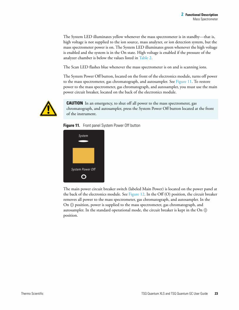
The System Power Off button, located on the front of the electronics module, turns off power to the mass spectrometer, gas chromatograph, and autosampler. See Figure 11. To restore power to the mass spectrometer, gas chromatograph, and autosampler, you must use the main power circuit breaker, located on the back of the electronics module.
Figure 11. Front panel System Power Off button
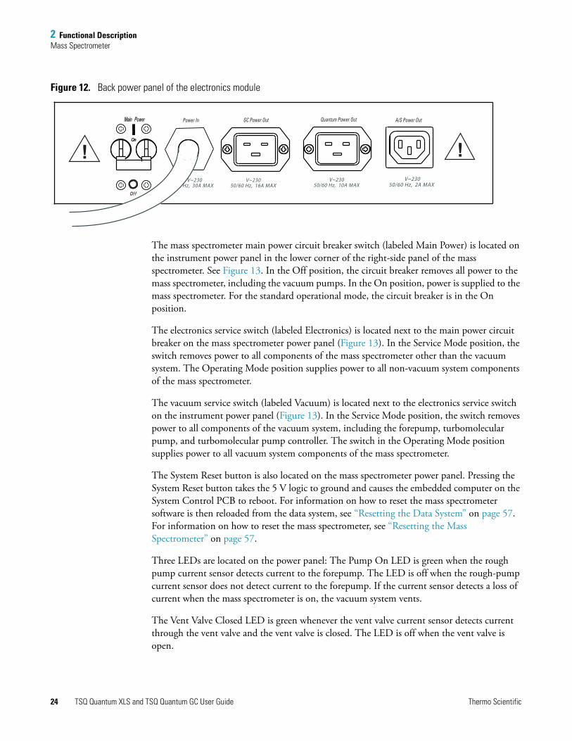
The main power circuit breaker switch (labeled Main Power) is located on the power panel at the back of the electronics module. See Figure 12. In the Off (O) position, the circuit breaker removes all power to the mass spectrometer, gas chromatograph, and autosampler. In the On (|) position, power is supplied to the mass spectrometer, gas chromatograph, and autosampler. In the standard operational mode, the circuit breaker is kept in the On (|) position.
CAUTION In an emergency, to shut off all power to the mass spectrometer, gas chromatograph, and autosampler, press the System Power Off button located at the front of the instrument.
System
System Power Off
Thermo Scientific TSQ Quantum XLS and TSQ Quantum GC User Guide 23
2 Functional DescriptionMass Spectrometer
Figure 12. Back power panel of the electronics module
The mass spectrometer main power circuit breaker switch (labeled Main Power) is located on the instrument power panel in the lower corner of the right-side panel of the mass spectrometer. See Figure 13. In the Off position, the circuit breaker removes all power to the mass spectrometer, including the vacuum pumps. In the On position, power is supplied to the mass spectrometer. For the standard operational mode, the circuit breaker is in the On position.
The electronics service switch (labeled Electronics) is located next to the main power circuit breaker on the mass spectrometer power panel (Figure 13). In the Service Mode position, the switch removes power to all components of the mass spectrometer other than the vacuum system. The Operating Mode position supplies power to all non-vacuum system components of the mass spectrometer.
The vacuum service switch (labeled Vacuum) is located next to the electronics service switch on the instrument power panel (Figure 13). In the Service Mode position, the switch removes power to all components of the vacuum system, including the forepump, turbomolecular pump, and turbomolecular pump controller. The switch in the Operating Mode position supplies power to all vacuum system components of the mass spectrometer.
The System Reset button is also located on the mass spectrometer power panel. Pressing the System Reset button takes the 5 V logic to ground and causes the embedded computer on the System Control PCB to reboot. For information on how to reset the mass spectrometer software is then reloaded from the data system, see “Resetting the Data System” on page 57. For information on how to reset the mass spectrometer, see “Resetting the Mass Spectrometer” on page 57.
Three LEDs are located on the power panel: The Pump On LED is green when the rough pump current sensor detects current to the forepump. The LED is off when the rough-pump current sensor does not detect current to the forepump. If the current sensor detects a loss of current when the mass spectrometer is on, the vacuum system vents.
The Vent Valve Closed LED is green whenever the vent valve current sensor detects current through the vent valve and the vent valve is closed. The LED is off when the vent valve is open.
! !
Power In GC Power Out Quantum Power Out A/S Power Out
V~230 50/60 Hz, 2A MAX
V~230 50/60 Hz, 10A MAX
V~230 50/60 Hz, 16A MAX
V~230 Hz, 30A MAX
24 TSQ Quantum XLS and TSQ Quantum GC User Guide Thermo Scientific

2 Functional DescriptionMass Spectrometer
The Ethernet Link OK LED is green when the System Control PCB is communicating with the data system PC. The LED is off when there is no communication between the System Control PCB and the data system PC.
Figure 13. Right-side power panel of the mass spectrometer
QualifiedService
PersonnelOnly
!
Electronics Vacuum
Pump On
Thermo Scientific TSQ Quantum XLS and TSQ Quantum GC User Guide 25

2 Functional DescriptionMass Spectrometer
EI/CI Ion Source
The EI/CI ion source forms gas phase sample ions from sample molecules that elute from the GC or are introduced by the direct sample probe. You can operate the ion source in either the electron ionization (EI) or chemical ionization (CI) mode. See “Ionization Modes” on page 4.
Figure 14. Ion source of the TSQ Quantum XLS mass spectrometer
Magnets and magnet yoke
Filament
EI/CI source PCB
Heater ring
Ion source block
Heated Q0 quadrupole lens assembly
L1, L2, L3, lens assembly
26 TSQ Quantum XLS and TSQ Quantum GC User Guide Thermo Scientific

2 Functional DescriptionMass Spectrometer
Figure 15. Ion source of the TSQ Quantum GC mass spectrometer
The ion volume, located in the center of the ion source, is the site where electrons interact with sample or reagent gas molecules to form ions. Three exchangeable ion volumes and ion volume holders are available for use in the ion source. See Figure 16. The choice of ion volume depends on the ionization mode. The open EI ion volume is open on the analyzer end, with a relatively large electron entrance hole. The closed EI ion volume has a smaller ion exit hole than the EI ion volume. This results in a higher pressure of analyte and greater sensitivity, but less dynamic range. The CI ion volume is closed on the analyzer end, except for a small ion exit hole and a relatively small electron entrance hole. In the CI mode, you must maintain a relatively high reagent gas pressure.
The ion source block holds the ion volume in its center. Samples are introduced from the GC capillary column through an aperture on the side of the ion source block and then into the ion volume. Gases for calibration or chemical ionization enter the ion volume through the transfer line.
Magnets and magnet yoke
Filament
EI/CI source PCB
Ion source block
L1, L2, L3, and L4 lens assembly
Heater ring
Thermo Scientific TSQ Quantum XLS and TSQ Quantum GC User Guide 27
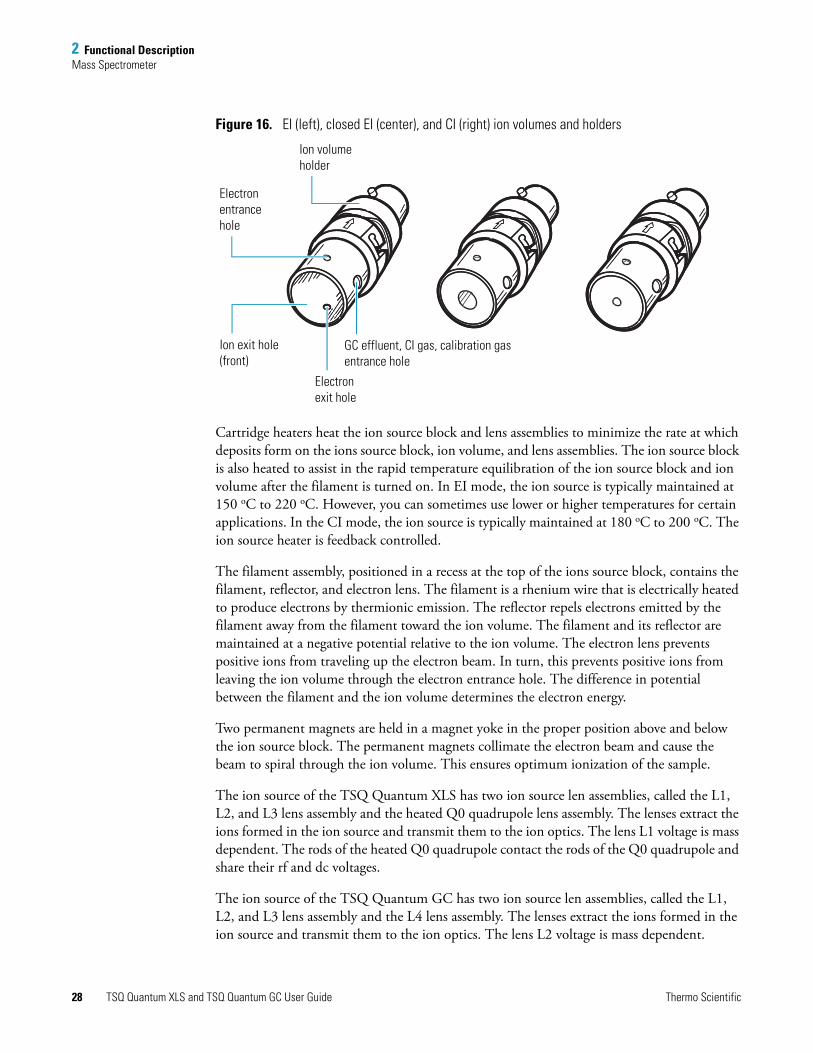
2 Functional DescriptionMass Spectrometer
Figure 16. EI (left), closed EI (center), and CI (right) ion volumes and holders
Cartridge heaters heat the ion source block and lens assemblies to minimize the rate at which deposits form on the ions source block, ion volume, and lens assemblies. The ion source block is also heated to assist in the rapid temperature equilibration of the ion source block and ion volume after the filament is turned on. In EI mode, the ion source is typically maintained at 150 oC to 220 oC. However, you can sometimes use lower or higher temperatures for certain applications. In the CI mode, the ion source is typically maintained at 180 oC to 200 oC. The ion source heater is feedback controlled.
The filament assembly, positioned in a recess at the top of the ions source block, contains the filament, reflector, and electron lens. The filament is a rhenium wire that is electrically heated to produce electrons by thermionic emission. The reflector repels electrons emitted by the filament away from the filament toward the ion volume. The filament and its reflector are maintained at a negative potential relative to the ion volume. The electron lens prevents positive ions from traveling up the electron beam. In turn, this prevents positive ions from leaving the ion volume through the electron entrance hole. The difference in potential between the filament and the ion volume determines the electron energy.
Two permanent magnets are held in a magnet yoke in the proper position above and below the ion source block. The permanent magnets collimate the electron beam and cause the beam to spiral through the ion volume. This ensures optimum ionization of the sample.
The ion source of the TSQ Quantum XLS has two ion source len assemblies, called the L1, L2, and L3 lens assembly and the heated Q0 quadrupole lens assembly. The lenses extract the ions formed in the ion source and transmit them to the ion optics. The lens L1 voltage is mass dependent. The rods of the heated Q0 quadrupole contact the rods of the Q0 quadrupole and share their rf and dc voltages.
The ion source of the TSQ Quantum GC has two ion source len assemblies, called the L1, L2, and L3 lens assembly and the L4 lens assembly. The lenses extract the ions formed in the ion source and transmit them to the ion optics. The lens L2 voltage is mass dependent.
Ion volume holder
Electron entrance hole
Ion exit hole (front)
Electron exit hole
GC effluent, CI gas, calibration gas entrance hole
28 TSQ Quantum XLS and TSQ Quantum GC User Guide Thermo Scientific

2 Functional DescriptionMass Spectrometer
In positive ion mode, the lenses are adjusted to a negative potential, and in negative ion mode, the lenses are adjusted to a positive potential. The arrangement of the lenses and their spacers enables quick and efficient pump-out of the ion source.
Inlet Valve
The inlet valve, which is attached to the front of the vacuum manifold, is a vacuum-sealed valve that allows you to change ion volumes or insert the direct exposure probe without venting the mass spectrometer to atmosphere. You use the insertion/removal (I/R) tool to insert or remove ion volumes. See Figure 17. The forepump evacuates the inlet valve.
The ball valve is a ball with a hole in it, and it is located between the vacuum manifold and the inlet valve block. The ball valve is open when the hole in the ball is aligned with the opening between the vacuum manifold and the inlet valve. The ball valve lever opens and closes the ball valve. When the ball valve is closed, it prevents the vacuum manifold from venting to atmosphere.
Figure 17. Inlet valve, I/R tool, guide bar, and ball valve lever
Inlet valve
I/R tool
Guide bar
Ball valve lever
Thermo Scientific TSQ Quantum XLS and TSQ Quantum GC User Guide 29

2 Functional DescriptionMass Spectrometer
Ion Optics
The ion optics focus the ions produced in the ion source and transmit them to the mass analyzer. The ion optics includes the Q0 quadrupole and lenses L11 and L12.
The Q0 quadrupole is a square array of square-profile rods that act as an ion transmission device. See Figure 19. An rf voltage applied to the rods gives rise to an electric field that guides the ions along the axis of the quadrupole. The Q0 offset voltage increases the translational kinetic energy of ions emerging from the ion source.
For the TSQ Quantum XLS, the Q0 quadrupole is split into two sections. See Figure 19. The smaller, heated Q0 quadrupole assembly attaches to the ion source, which heats it with the cartridge heaters. The rods of the heated Q0 quadrupole make electrical contact with the rods of the larger Q0 quadrupole.
Figure 18. Q0 quadrupole of the TSQ Quantum GC
Figure 19. Heated Q0 quadrupole (left) and Q0 quadrupole (right) of the TSQ Quantum XLS
Figure 20 gives a cross-sectional view of the transfer line, ion source, heated Q0 quadrupole, and Q0 quadrupole of the TSQ Quantum XLS.
Figure 21 gives a cross-sectional view of the transfer line, ion source, and Q0 quadrupole of the TSQ Quantum GC.
30 TSQ Quantum XLS and TSQ Quantum GC User Guide Thermo Scientific

2 Functional DescriptionMass Spectrometer
Figure 20. Cross-sectional view of the transfer line, ion source, heated Q0 quadrupole, and Q0 quadrupole of the TSQ Quantum XLS instrument
Q0 quadrupole
Heated Q0 quadrupoleLens L1
Ion source ion volumeLens L3
Lens L2
Transfer line
Capillary column
Thermo Scientific TSQ Quantum XLS and TSQ Quantum GC User Guide 31

2 Functional DescriptionMass Spectrometer
Figure 21. Cross-sectional view of the transfer line, ion source, and Q0 quadrupole of the TSQ Quantum GC
The L11 and L12 lenses are metal disks with a circular hole in the center that the ion beam can pass through. Together they act as a two-element cone lens. You can apply an electrical potential to the lens to accelerate (or decelerate) ions as they approach the lens and focus the ion beam as it passes through the lens. The value ranges between 0 and ±300 V. Lenses L11 and L12 also act as a vacuum baffle between the Q0 quadrupole chamber and the mass analyzer chamber.
Q0 quadrupoleLens L1
Ion source ion volumeLens L4
Lens L3
Lens L2
Transfer line
Capillary column
32 TSQ Quantum XLS and TSQ Quantum GC User Guide Thermo Scientific
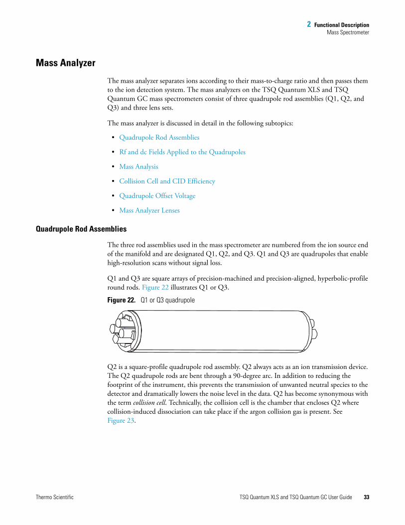
2 Functional DescriptionMass Spectrometer
Mass Analyzer
The mass analyzer separates ions according to their mass-to-charge ratio and then passes them to the ion detection system. The mass analyzers on the TSQ Quantum XLS and TSQ Quantum GC mass spectrometers consist of three quadrupole rod assemblies (Q1, Q2, and Q3) and three lens sets.
The mass analyzer is discussed in detail in the following subtopics:
• Quadrupole Rod Assemblies
• Rf and dc Fields Applied to the Quadrupoles
• Mass Analysis
• Collision Cell and CID Efficiency
• Quadrupole Offset Voltage
• Mass Analyzer Lenses
Quadrupole Rod Assemblies
The three rod assemblies used in the mass spectrometer are numbered from the ion source end of the manifold and are designated Q1, Q2, and Q3. Q1 and Q3 are quadrupoles that enable high-resolution scans without signal loss.
Q1 and Q3 are square arrays of precision-machined and precision-aligned, hyperbolic-profile round rods. Figure 22 illustrates Q1 or Q3.
Figure 22. Q1 or Q3 quadrupole
Q2 is a square-profile quadrupole rod assembly. Q2 always acts as an ion transmission device. The Q2 quadrupole rods are bent through a 90-degree arc. In addition to reducing the footprint of the instrument, this prevents the transmission of unwanted neutral species to the detector and dramatically lowers the noise level in the data. Q2 has become synonymous with the term collision cell. Technically, the collision cell is the chamber that encloses Q2 where collision-induced dissociation can take place if the argon collision gas is present. See Figure 23.
Thermo Scientific TSQ Quantum XLS and TSQ Quantum GC User Guide 33

2 Functional DescriptionMass Spectrometer
Figure 23. Collision cell, Q2 quadrupole, and lenses
Rf and dc Fields Applied to the Quadrupoles
In a quadrupole rod assembly, because rods opposite each other in the array connect electrically, you can consider the four rods as two pairs of two rods each. Ac and dc voltages are applied to the rods and these voltages are ramped during the scan. Voltages of the same amplitude and sign are applied to the rods of each pair. However, the voltages applied to the different rod pairs are equal in amplitude but opposite in sign. See Figure 24.
Figure 24. Polarity of the rf and dc voltages applied to the rods of the Q1 and Q3 mass analyzers
The ac voltage applied to the quadrupole rods is of constant frequency (1.123 MHz). The ac voltage applied to the rods varies from 0 to 10 000 V P/P, and the dc voltage varies from 0 to ±840 V. Voltages of the same amplitude and sign are applied to each rod pair. However, the voltages applied to the other rod pair are equal in amplitude but opposite in sign.
Lenses L21, L22, and L23
Lenses L31, L32,and L33
rf voltage+ dc voltage
rf voltage 180° out of phase –dc voltage
34 TSQ Quantum XLS and TSQ Quantum GC User Guide Thermo Scientific

2 Functional DescriptionMass Spectrometer
Because the frequency of this ac voltage is in the radio frequency range, you refer to it as rf voltage. In Figure 25, the solid line represents the combined rf and dc voltage applied to one rod pair, and the dashed line represents the combined rf and dc voltage applied to the other rod pair. The ratio of rf voltage to dc voltage determines the ability of the mass spectrometer to separate ions of different mass-to-charge ratios.
The first and third quadrupole rod assemblies (Q1 and Q3 quadrupoles) can act as mass analyzers or as ion transmission devices. When both rf and dc voltages are applied, Q1 and Q3 function as mass analyzers. When only rf voltage is applied, they act as ion transmission devices. In the ion transmission mode, the quadrupole rod assemblies allow ions in a wide window of mass-to-charge ratios to pass.
The square quadrupole rod assembly (Q2) operates in the ion transmission mode only. Surrounding Q2 is a collision cell where collision-induced dissociation (CID) can take place if the argon collision gas is present in the cell.
Figure 25. Magnitude of the rf and dc voltages applied to the rods of the Q1 and Q3 mass analyzers
10,000 V P/P 840 V DC VOLTAGE
Thermo Scientific TSQ Quantum XLS and TSQ Quantum GC User Guide 35

2 Functional DescriptionMass Spectrometer
Mass Analysis
The Q1 and Q3 rods are charged with a variable ratio of rf voltage and dc voltage (Figure 25). These potentials give rise to an electrostatic field that gives stable oscillations to ions with a specific mass-to-charge ratio and unstable oscillations to all others.
At any given instant, one particular set of rf and dc voltage values is being applied to the mass analyzer rods. Under these conditions, only ions of one mass-to-charge ratio (for example, m/z 180) are maintained within bounded oscillations as their velocity carries them through the mass analyzer. During this same time, all other ions undergo unbounded oscillations. These ions strike one of the rod surfaces, become neutralized, and are pumped away, or they are ejected from the rod assembly.
Then, at a later time, both rf and dc voltages change, and ions of the next mass-to-charge ratio (for example, m/z 181) are allowed to pass, while all other ions (including m/z 180) become unstable and undergo unbounded oscillations. This process continues, with ions of one mass-to-charge ratio after another being transmitted, as the rf and dc voltages change in value. The potentials on the quadrupole rods can be changed rapidly and precisely. At the end of the scan, the mass spectrometer discharges the rf and dc voltages to zero and repeats the process.
The precision quadrupole rods of the mass spectrometer provide excellent sensitivity, peak shape, resolution, and high mass transmission.
Collision Cell and CID Efficiency
In the MS/MS scan modes, the mass spectrometer applies a large voltage of opposite polarity to the Q2 rod pairs between scans, which empties the collision cell. This process ensures that no ions remain in the collision cell from scan to scan.
The collision cell quadrupole rod assembly (Q2), which always acts as an ion transmission device, is a quadrupole array of square-profile rods. A variable rf voltage charges the rods, which creates an electrostatic field that gives stable oscillations to ions in a wide window of mass-to-charge ratios.
The collision cell surrounds Q2 and is usually pressurized from about 1 × 10⁻³ to 4 × 10⁻³ Torr with argon collision gas. The collision cell is where collision-induced dissociation (CID) takes place.
CID is a process in which an ion collides with a neutral atom or molecule and then, because of the collision, dissociates into smaller fragments. The mechanism of dissociation involves converting some of the translational kinetic energy (TKE) of the ion into internal energy. This collision places the ion in an excited state. If the internal energy is sufficient, the ion fragments.
36 TSQ Quantum XLS and TSQ Quantum GC User Guide Thermo Scientific

2 Functional DescriptionMass Spectrometer
Three expressions convey the efficiency of the CID process:
• Collection efficiency
• Fragmentation efficiency
• Overall CID efficiency
Collection efficiency: The ion flux ratio measured at the exit of the collision cell and at its entrance. With no collision gas present, the mass spectrometer obtains virtually 100 percent collection efficiency. Collection efficiency is a mass-dependent parameter. For example, with mid-range collision gas pressure, the collection efficiency might vary from about 50 percent for comparatively less massive ions (which are more prone to scatter) up to 75 percent for comparatively more massive ions (which are less prone to scatter).
Fragmentation efficiency: The fraction of the ion flux at the exit of the collision cell that results from fragmented ions. Fragmentation efficiency depends directly on the stability of the ion and indirectly on the mass of the ion. The more stable the ion, the less likely a given collision will fragment the ion. Typically, low mass ions require a higher collision energy to dissociate than high mass ions. To compensate for this, you can use the data system to specify a mass-dependent collision energy ramp.
With a mid-range collision gas pressure, fragmentation efficiency might vary from 15 percent to 65 percent for various compounds. As the collision gas pressure increases, the fragmentation efficiency for all compounds approaches 100 percent due to multiple collisions. The collection efficiency decreases, however, due to scattering.
Overall CID efficiency: The product of the collection efficiency and the fragmentation efficiency. The overall CID efficiency exhibits a maximum with intermediate pressure. As the pressure is increased beyond the optimum value, more and more collisions take place, the probability of scattering increases, and fewer and fewer ions pass through the collision cell. This results in the collection efficiency decreasing. The fragmentation efficiency also decreases as the pressure is decreased from its optimum value, because fewer and fewer collisions take place.
Quadrupole Offset Voltage
The quadrupole offset voltage is a dc potential applied to the quadrupole rods in addition to the ramping dc voltage. The offset voltage applied to the two rod pairs of the assemblies is equal in magnitude and equal in sign. Because the quadrupole offset voltage accelerates or decelerates ions, it sets the TKE of the ions as they enter the quadrupole rod assembly.
In general, for a given experiment, the mass spectrometer has fixed offset voltages for Q1 and Q2. However, in MS/MS experiments, the quadrupole offset voltage applied to Q3 usually varies as a scan proceeds. The mass spectrometer automatically computes the Q3 quadrupole offset voltage necessary and then varies the voltage, as appropriate, as each scan proceeds.
Thermo Scientific TSQ Quantum XLS and TSQ Quantum GC User Guide 37

2 Functional DescriptionMass Spectrometer
The offset voltage applied to Q2 (which contains the collision cell) is responsible for the collision energy. The collision energy is the difference in potential between the ion source (where parent ions are formed) and Q2 (where they collide with collision gas). As the offset voltage on Q2 increases, the TKE of the parent ions also increases. As a result, increases in the Q2 offset voltage increase the energy of ion/Ar collisions. The collision energy is usually ramped downward with m/z to promote the fragmentation of low mass ions.
Before obtaining any mass spectra, the mass spectrometer tunes Q1 in the Q1MS scan mode (Q2 and Q3 rf voltage only), and tunes Q3 in the Q3MS scan mode (Q1 and Q2 rf voltage only). During tuning, the mass spectrometer determines the optimum quadrupole offset voltage for Q1 and for Q3.
Mass Analyzer Lenses
The TSQ Quantum XLS and TSQ Quantum GC mass analyzers have three lens sets. See Figure 23 on page 34. Those between Q1 and Q2 are designated L21, L22, L23; those between Q2 and Q3 are designated L31, L32, L33; and the lens between Q3 and the ion detection system is designated the exit lens. All of the lenses have circular holes in their centers that the ion beam passes through.
The lens assemblies also retain the three rod assemblies to ensure accurate and automatic axial alignment of the rod assemblies.
The L2x lens set (between Q1 and Q2) and the L3x lens set (between Q2 and Q3) serve these functions:
• To minimize the amount of collision gas that enters the mass analyzers (Q1 and Q3) from the collision cell (Q2). Lenses L22 and L21 on one side of Q2 and lenses L32 and L33 on the other side of Q2 act as baffles. (For high-mass transmission, be sure to maintain a low pressure in the mass analyzers.)
• To retain the collision gas. Lenses L23 and L3 form two of the walls of the collision cell, so they tend to hold the collision gas in the collision cell. The collision gas escapes, however, through the same lens holes that the ion beam passes through.
• To shield Q1 from the rf voltage applied to Q2 and vice versa (L2x lens set) and to shield Q3 from the rf voltage applied to Q2 and vice versa (L3x lens set).
• To focus the ion beam. The three lenses between Q1 and Q2 (and those between Q2 and Q3) together form a three-element aperture lens. The first and third lenses are generally set to similar or identical values and the central lens is set to a value different (either higher or lower) from the other two.
38 TSQ Quantum XLS and TSQ Quantum GC User Guide Thermo Scientific

2 Functional DescriptionMass Spectrometer
The voltage applied to each of the lenses can vary from about –300 to +300 V. Typically, however, the voltage applied to the first and third elements of the L2x lens set is somewhat greater than the quadrupole offset voltage applied to Q1. Because the Q1 quadrupole offset voltage is generally set to about ±5 V (depending on the charge of the ions of interest), the voltage applied to lenses L21 and L23 is typically about –10 V for positive ions and +10 V for negative ions. The voltage applied to the central lens of the L2x lens set is typically about ±225 V.
In the Q3MS scan mode, the voltage applied to the lenses of the L3x lens set is about the same as that applied to the corresponding lens in the L2x lens set. Note, however, that in the MS/MS scan modes, the voltage applied to the L3x lens set automatically varies with the quadrupole offset voltage applied to Q3. As the Q3 quadrupole offset voltage ramps, the voltages applied to the lenses ramp correspondingly.
The exit lens is located between Q3 and the ion detection system. The exit lens is held at ground potential. Its purpose is to shield Q3 from the high voltage applied to the ion detection system and to shield the ion detection system from the high rf voltages applied to Q3.
Ion Detection System
The TSQ Quantum XLS and TSQ Quantum GC mass spectrometers are equipped with a high-sensitivity, off-axis ion detection system. See Figure 26. This system produces a high signal-to-noise ratio and provides for voltage polarity switching between positive ion and negative ion modes of operation. The ion detection system includes a 15 kV conversion dynode and a channel electron multiplier. The ion detection system is located on the back of the vacuum manifold behind the mass analyzer.
The conversion dynode is a concave metal surface located at a right angle to the ion beam. The mass spectrometer applies to the conversion dynode a potential of +15 kV for negative ion detection or –15 kV for positive ion detection. When an ion strikes the surface of the conversion dynode, one or more secondary particles are produced. These secondary particles can include positive ions, negative ions, electrons, and neutrals. When positive ions strike a negatively charged conversion dynode, the secondary particles of interest are negative ions and electrons. When negative ions strike a positively charged conversion dynode, the secondary particles of interest are positive ions. The curved surface of the conversion dynode focuses these secondary particles and a voltage gradient accelerates the particles into the electron multiplier.
The electron multiplier includes a cathode and an anode. The cathode of the electron multiplier is a lead-oxide, funnel-like resistor. The high voltage ring applies a potential of up to –2.5 kV to the cathode. The exit end of the cathode (at the anode) is near ground potential.
The anode of the electron multiplier is a small cup located at the exit end of the cathode. The anode collects the electrons produced by the cathode. The anode screws into the anode feedthrough in the base plate.
Thermo Scientific TSQ Quantum XLS and TSQ Quantum GC User Guide 39

2 Functional DescriptionMass Spectrometer
Figure 26. Ion detection system, showing the electron multiplier (top) and conversion dynode (bottom)
Secondary particles from the conversion dynode strike the inner walls of the electron multiplier cathode with sufficient energy to eject electrons. The ejected electrons are accelerated farther into the cathode, drawn by the increasingly positive potential gradient. The funnel shape of the cathode causes the ejected electrons not to travel far before they again strike the inner surface of the cathode, which causes the emission of more electrons. A cascade of electrons is then created that finally results in a measurable current at the end of the cathode where the anode collects the electrons. The current collected by the anode is proportional to the number of secondary particles striking the cathode.
Typically, the electron multiplier is set to a gain of about 3 × 10⁵ (that is, for each ion or electron that enters, 3 × 10⁵ electrons exit) in MS mode and 2 × 10⁶ in MS/MS mode. The electrometer circuit converts the current that leaves the electron multiplier via the anode to a voltage, and the data system records the voltage.
The ion detection system of the mass spectrometer increases signal and decreases noise. The high voltage applied to the conversion dynode results in a high conversion efficiency and increased signal—that is, each ion that strikes the conversion dynode produces many secondary particles. The increase in conversion efficiency is more pronounced for more massive ions than it is for less massive ions.
Because of the off-axis orientation of the ion detection system relative to the mass analyzer, neutral molecules from the mass analyzer tend not to strike the conversion dynode or electron multiplier. As a result, noise from neutral molecules is reduced.
40 TSQ Quantum XLS and TSQ Quantum GC User Guide Thermo Scientific

2 Functional DescriptionMass Spectrometer
Vacuum System and Inlet Gasses Hardware
The vacuum system evacuates the region around the ion source, ion optics, mass analyzer, and ion detection system. The principal components of the vacuum system include the following:
• Vacuum Manifold
• Turbomolecular Pump
• Forepump
• Convectron Gauges
• Ion Gauge
The inlet gasses hardware controls the flow of collision gas, CI reagent gas, calibration compound, and air (during venting) into the mass spectrometer. The hardware for the inlet gases includes the following components:
• Vent Valve
• Collision Gas Flow Control Valves
• Calibration Compound and CI Reagent Gas Flow Control
Figure 27 shows a functional block diagram of the vacuum system and inlet gasses hardware.
Figure 27. Functional block diagram of the vacuum system and inlet gases hardware
Collisioncell
Collision gasdivert valve
Collisiongas valve
Argongas port
Convectrongauge
Exhaust
Forepump
Convectrongauge
Iongauge
Transfer lineGaschromatograph
CI reagentgas valve
CI reagentgas port
Calibration compound
valve
Calibration compound
vial
Inletvalve
Dual-inletturbomolecular pump
Analyzerchamber
Ion sourcechamber
Q0 quadrupolechamber
Ventvalve
(3 x 10 - 6 Torr)(4 x 10 - 5 Torr)
Nitrogen orfiltered air
Thermo Scientific TSQ Quantum XLS and TSQ Quantum GC User Guide 41

2 Functional DescriptionMass Spectrometer
Vacuum Manifold
The vacuum manifold encloses the ion source, ion optics, mass analyzer, and ion detection system assemblies. The vacuum manifold is a thick-walled, aluminum chamber with two removable side cover plates, with openings on the front, sides, and top, and various electrical feedthroughs and gas inlets.
The main vacuum manifold is divided into two chambers by a baffle. See Figure 28. The high vacuum port of the turbomolecular pump evacuates the region inside the first chamber, called the analyzer region, to less than 10-5 Torr. The turbomolecular pump then discharges into the forepump through the foreline.
The region inside the second chamber, called the Q0 quadrupole region, is evacuated to 1 mTorr by the interstage port of the turbomolecular vacuum pump.
A second vacuum manifold houses the ion source, which is open to the Q0 quadrupole chamber. The interstage port of the turbomolecular pump also evacuates the ion source region.
When CID is turned on, the collision cell chamber, inside the analyzer chamber, has a user-controlled argon pressure of between 1 and 4 mTorr. The forepump evacuates the argon in the collision cell when CID is turned off.
Two removable side cover plates on the left side of the vacuum manifold allow access to the Q0 ion optics, mass analyzer, and ion detection system. Two electrically conductive O-rings provide a vacuum-tight seal between the side cover plates and the vacuum manifold.
42 TSQ Quantum XLS and TSQ Quantum GC User Guide Thermo Scientific

2 Functional DescriptionMass Spectrometer
Figure 28. Vacuum manifold (interior)
Turbomolecular Pump
A Leybold TW220/150/15S double-inlet turbomolecular pump provides the vacuum for the ion source, Q0 quadrupole region, and analyzer region of the vacuum manifold. The turbomolecular pump mounts onto the top of the vacuum manifold (Figure 28).
The turbomolecular pump has two pumping inlets:
• A high-vacuum inlet at the top of the rotor stack, which evacuates the analyzer chamber
• An interstage inlet about halfway down the rotor stack, which evacuates the ion source and Q0 quadrupole chambers
Ion gaugeO-ring Turbomolecular pump
Collision cell chamber
Analyzer chamber
Q0 quadrupole chamber
Ion source chamber
Baffle
Thermo Scientific TSQ Quantum XLS and TSQ Quantum GC User Guide 43

2 Functional DescriptionMass Spectrometer
The turbomolecular pump is controlled by a Leybold TDS controller and powered by a +24 V dc (250 W) power supply. The mass spectrometer circuit breaker switch and the vacuum service switch, but not the electronics service switch, turn power for the turbomolecular pump off and on. A fan draws air in from the front of the instrument to cool the pump.
Power to the turbomolecular pump shuts off if the foreline pressure, as measured by the Convectron™ gauge, is too high, or if the turbomolecular temperature is too high.
Forepump
An Edwards™ E2M30 forepump (or roughing pump) establishes the vacuum necessary for the proper operation of the turbomolecular pump. The forepump also evacuates the inlet valve and the collision cell. The pump has a maximum displacement of 650 L/min and maintains a minimum pressure of approximately 1 Pa (0.01 Torr).
The forepump is connected to the turbomolecular pump by a section of reinforced PVC tubing. The power cord of the forepump is plugged into the outlet labeled Forepump on the power panel (see Figure 13 on page 25). This outlet supplies power to the pump and is controlled by the main power circuit breaker switch and vacuum service switch, not by the electronics service switch.
Convectron Gauges
A Convectron gauge measures the pressure in the inlet valve and the foreline, which connects the turbomolecular pump and the forepump. A second Convectron gauge measures the pressure of argon collision gas in the collision cell.
The Convectron gauge uses a Wheatstone bridge with a temperature dependent resistor to measure pressure down to a fraction of a mTorr. The voltage present at the top of the bridge depends on how fast the resistor can radiate heat, which is related to the pressure. The pressure that the Convectron gauge measures is monitored by vacuum protection circuitry on the Source PCB, which in turn is monitored by the embedded computer on the System Control PCB. The vacuum protection circuitry detects whether the foreline pressure is too high for the proper operation of the turbomolecular pump.
Ion Gauge
A Granville-Phillips™ 342 mini ion gauge measures the pressures in the analyzer region of the vacuum manifold. The ion gauge produces energetic electrons that cause the ionization of molecules in the ion gauge. Positive ions formed in the ion gauge are attracted to a collector. The collector current is related to the pressure in the vacuum manifold. The ion gauge is also involved in vacuum protection.
CAUTION Always plug the forepump power cord into the outlets labeled Forepump on the right side power panel of the mass spectrometer. Never plug it directly into a wall outlet.
44 TSQ Quantum XLS and TSQ Quantum GC User Guide Thermo Scientific
2 Functional DescriptionMass Spectrometer
Vent Valve
The vent valve, located in the area of Q2, allows the vacuum manifold to be vented with nitrogen, if you have a nitrogen cylinder connected, or else with air that has been filtered through a sintered nylon filter. The vent valve is a solenoid-operated valve, which is controlled by the Vent Delay PCB. When the solenoid is energized, the vent valve closes. If the power fails or the main power circuit breaker is placed in the Off (O) position, a 4-farad capacitor located in the Power Entry Module keeps the solenoid in the closed position for several minutes. If power is not restored in this time, then the solenoid opens and the system is vented with nitrogen or filtered air. The vent valve closes after power is restored to the mass spectrometer.
Collision Gas Flow Control Valves
The collision gas flow control valves control the flow of argon collision gas into and out of the Q2 collision cell. A solenoid valve acts to shut off argon gas flow to the cell. The collision gas pressure is regulated by a proportional valve that is controlled by the data system. You can set the collision gas pressure (0 to 5 mTorr) in the Define Scan dialog box of the EZ Tune window.
Ions enter the Q2 collision cell, collide with the argon collision gas, and then, because of the collision, dissociate into smaller fragments. See “Collision Cell and CID Efficiency” on page 36.
Argon enters the mass spectrometer through a 1/8 in. port on the left side of the mass spectrometer.
A second proportional valve allows the forepump to evacuate the Q2 collision cell of argon and waste gases when CID is turned off. The mass spectrometer automatically opens and closes the collision gas evacuation valve, depending on whether Q2 is acting as an ion transmission device or a collision cell.
Calibration Compound and CI Reagent Gas Flow Control
The calibration compound gas flow control valve controls the flow of calibration compound gas into the ion source, via the transfer line. The calibration gas flow can be either high or low. Normally, you use low flow, but high flow might be necessary for negative ion CI calibration.
The CI gas flow control valve controls the flow of chemical ionization reagent gas into the ion source, via the transfer line. The maximum CI gas flow rate is about 4 mL/min, depending on the gas.
Thermo Scientific TSQ Quantum XLS and TSQ Quantum GC User Guide 45

2 Functional DescriptionMass Spectrometer
Electronic Assemblies
The electronic assemblies that control the operation of the mass spectrometer are distributed among various PCBs and other modules located in the tower, in the embedded computer, and on or around the vacuum manifold of the mass spectrometer.
The Power Entry Module provides the following:
• Mass spectrometer power control• A contact closure interface• Vent valve control• An Ethernet 100 base-T connection from the System Control PCB to the data system PC• A mechanical pump failure protection circuit (linked to vent valve control)• A system reset button• Status LEDs• Service ports
The right-side power panel, shown in Figure 13 on page 25, is part of the Power Entry Module.
The Power Entry Module accepts line power, filters it, and provides it to various components of the mass spectrometer. The Power Module includes these components:
• Main power circuit breaker switch• Surge suppressor• Line filter• Electronics service switch• Vacuum service switch
The “brains” of the TSQ Quantum XLS and TSQ Quantum GC mass spectrometers are the System Control PCBs. The System Control PCB and embedded computer include the following:
• PowerPC processor• Serial Peripheral Interconnect (SPI) bus• I/O coprocessor• Super Harvard Architecture Computer (Sharc) bus• Scan generator DSP• Acquisition processor DSP• Interbus bridge• 100 base-T Ethernet port
46 TSQ Quantum XLS and TSQ Quantum GC User Guide Thermo Scientific
2 Functional DescriptionData System
The rf voltage generation electronic assemblies produce the Q0, Q1, Q2, and Q3 rf voltages that enable ion transmission and mass analysis. All rf voltages are controlled by the Analyzer Control PCB and the System Control PCB.
The Q1 and Q3 rf voltage amplifier circuits are identical, and the circuits for Q0 and Q2 are similar.
The rf voltage generation electronic assemblies include the following components:
• rf oscillator• rf Voltage Amplifier PCB• Low Pass Filter PCB• rf voltage coil• rf voltage detector• Mass DAC• Integrating amplifier
The ion detection system electronic assemblies provide high voltage to the electron multiplier and conversion dynode of the ion detection system. They also receive the electron multiplier output current signal, convert it to a voltage (by the electrometer circuit), and pass it to the embedded computer.
The ion detection system electronic assemblies include the following:
• Electron multiplier power supply• Conversion dynode power supply• Electrometer PCB• Acquisition DSP
The Analyzer Control PCB contains circuitry for controlling and monitoring the operation of the ion source, ion optics, mass analyzer, and ion detection system. These circuits are in turn monitored by the PowerPC processor of the System Control PCB via the SPI bus.
The Analyzer Control PCB controls and monitors the rf voltages for Q0, Q1, Q2, and Q3 quadrupoles. It also has lens voltage drivers that convert ±330 V dc power from the DC Rod Driver PCB to dc voltages that are applied to the lenses.
Data SystemThe data system controls and monitors the TSQ Quantum XLS and TSQ Quantum GC mass spectrometers. The data system also processes data that the mass spectrometer acquires. The data system is composed of the following:
• Computer Hardware
• Data System/Mass Spectrometer/GC Interface
• Data System/Local Area Network Interface
Thermo Scientific TSQ Quantum XLS and TSQ Quantum GC User Guide 47

2 Functional DescriptionData System
Computer Hardware
These are the major features of the data system computer:
• Intel™ Pentium™ IV processor• High capacity hard disk drive• Recordable/rewriteable CD drive• Primary Ethernet port (data system to mass spectrometer)• Secondary Ethernet port (data system to local area network)• High performance video graphics card • CDRW drive• DVD drive• 1280×1024 resolution color monitor• Keyboard and mouse
For more information about the computer, refer to the appropriate manuals.
Data System/Mass Spectrometer/GC Interface
The data system computer contains a 100 base-T Ethernet adapter (called the primary Ethernet adapter) that is dedicated to data system/mass spectrometer/GC communication. This primary Ethernet adapter communicates with the mass spectrometer and GC modules via a 10/100 base-T Ethernet switch. The Ethernet adapter on the mass spectrometer resides on the System Control PCB. A twisted pair, Ethernet cable connects the primary Ethernet adapter of the data system to the Ethernet switch, which is connected to the Ethernet connector on the power panel of the mass spectrometer and to the GC.
Data System/Local Area Network Interface
The data system computer contains a secondary Ethernet adapter. This secondary Ethernet adapter is not involved in data system/mass spectrometer or GC communications. You can use this secondary Ethernet adapter to access your local area network.
48 TSQ Quantum XLS and TSQ Quantum GC User Guide Thermo Scientific
3
System Shutdown, Startup, and Reset
Many maintenance procedures for the TSQ Quantum XLS and TSQ Quantum GC systems require that the mass spectrometer be shut down completely. In addition, you can place the mass spectrometer in Standby mode if you plan to not use the system for 12 hours or more.
Shutting Down the System in an EmergencyYou can turn off all power to the mass spectrometer, gas chromatograph, and autosampler by pressing the System Power Off button, located on the front of the electronics module, or the main power circuit breaker, located on the back of the electronics module. You can turn on the system power only with the main power circuit breaker on the back of the electronics module and not the System Power Off switch.
To turn off the mass spectrometer in an emergency
Contents
• Shutting Down the System in an Emergency
• Placing the System in Standby Mode
• Shutting Down the System Completely
• Starting Up the System after a Complete Shutdown
• Resetting the Mass Spectrometer
• Resetting the Data System
• Turning Off Selected Mass Spectrometer Components
CAUTION Press the System Power Off button located on the front of the electronics module. See Figure 29. The System Power Off button turns off all power to the mass spectrometer (including the vacuum pumps), gas chromatograph, and autosampler. Although removing power abruptly does not harm components within the system, under normal conditions do not shut down the system using the System Power Off button. For the recommended procedure, see “Shutting Down the System Completely” on page 51.
Thermo Scientific TSQ Quantum XLS and TSQ Quantum GC User Guide 49

3 System Shutdown, Startup, and ResetShutting Down the System in an Emergency
Figure 29. System Power Off button on the front of the electronics module
Figure 30. Power panel on the back of the electronics module
System Power Off button
! !
Power In GC Power Out Quantum Power Out A/S Power Out
V~230 50/60 Hz, 2A MAX
V~230 50/60 Hz, 10A MAX
V~230 50/60 Hz, 16A MAX
V~230 Hz, 30A MAX
50 TSQ Quantum XLS and TSQ Quantum GC User Guide Thermo Scientific

3 System Shutdown, Startup, and ResetPlacing the System in Standby Mode
Placing the System in Standby ModeIf you are not going to use the TSQ Quantum XLS or TSQ Quantum GC system for a short period of time, such as overnight or over weekends, you do not need to shut it down completely. When you are not going to operate the system for 12 hours or more, you can leave the system in Standby mode.
To place the TSQ Quantum XLS or TSQ Quantum GC system in Standby mode
1. Wait until data acquisition, if any, is complete.
2. From the TSQ EZ Tune window, choose Control > Standby (or click the On/Standby button) to put the mass spectrometer in standby.
When you choose Control > Standby, the TSQ Quantum XLS or TSQ Quantum GC system turns off the electron multiplier, the conversion dynode, the ion source filament and lenses (but not the heater), and the mass analyzer and ion optics rf voltages. See Table 4 on page 59 for the On/Off status of mass spectrometer components when the mass spectrometer is in Standby mode. The System LED on the front panel of the mass spectrometer illuminates yellow when the system is in standby.
3. Leave the mass spectrometer power on.
4. Leave the GC power on with column flow.
5. Leave the autosampler power on.
6. Leave the data system power on.
Shutting Down the System CompletelyShut down the TSQ Quantum XLS or TSQ Quantum GC system completely only when you do not use it for an extended period, or if it must be shut down for a maintenance or service procedure. For a short period of time, such as overnight or over weekends, you can place the system in Standby mode. See “Placing the System in Standby Mode.”
To shut down the TSQ Quantum XLS or TSQ Quantum GC system completely
1. Cool the GC, transfer line, and ion source:
• GC oven: 30 °C
• Injector: off
• Transfer line: off
• Ion source: 30 °C
On
Off
Standby
Note If you do not plan to change the column or perform maintenance on the gas chromatograph, you do not have to lower the injector temperature.
Thermo Scientific TSQ Quantum XLS and TSQ Quantum GC User Guide 51
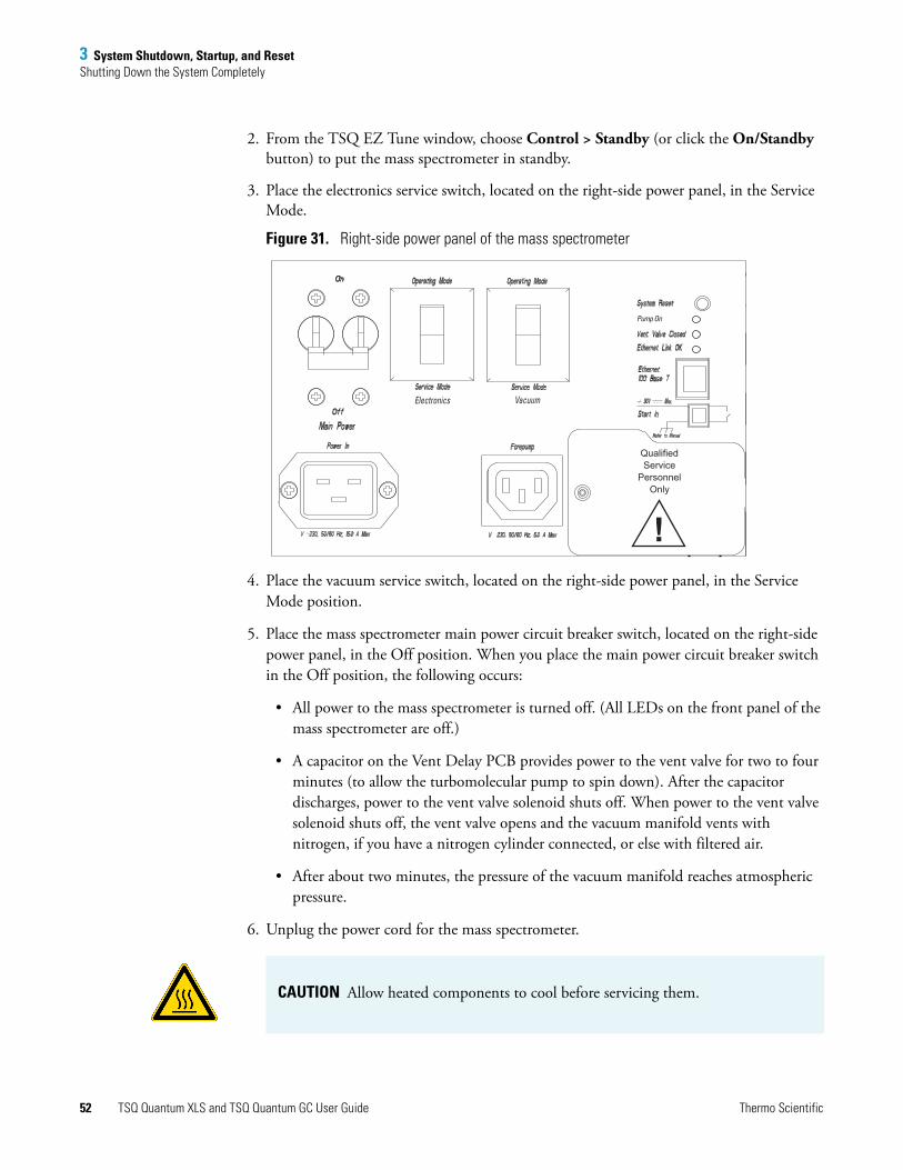
3 System Shutdown, Startup, and ResetShutting Down the System Completely
2. From the TSQ EZ Tune window, choose Control > Standby (or click the On/Standby button) to put the mass spectrometer in standby.
3. Place the electronics service switch, located on the right-side power panel, in the Service Mode.
Figure 31. Right-side power panel of the mass spectrometer
4. Place the vacuum service switch, located on the right-side power panel, in the Service Mode position.
5. Place the mass spectrometer main power circuit breaker switch, located on the right-side power panel, in the Off position. When you place the main power circuit breaker switch in the Off position, the following occurs:
• All power to the mass spectrometer is turned off. (All LEDs on the front panel of the mass spectrometer are off.)
• A capacitor on the Vent Delay PCB provides power to the vent valve for two to four minutes (to allow the turbomolecular pump to spin down). After the capacitor discharges, power to the vent valve solenoid shuts off. When power to the vent valve solenoid shuts off, the vent valve opens and the vacuum manifold vents with nitrogen, if you have a nitrogen cylinder connected, or else with filtered air.
• After about two minutes, the pressure of the vacuum manifold reaches atmospheric pressure.
6. Unplug the power cord for the mass spectrometer.
QualifiedService
PersonnelOnly
!
Electronics Vacuum
Pump On
CAUTION Allow heated components to cool before servicing them.
52 TSQ Quantum XLS and TSQ Quantum GC User Guide Thermo Scientific

3 System Shutdown, Startup, and ResetStarting Up the System after a Complete Shutdown
7. Turn off the GC. Follow the procedure described in the manual that came with the GC.
8. Turn off the autosampler by using the main power on/off switch.
9. Press the System Power Off button (Figure 29) to remove all power from the TSQ Quantum XLS or TSQ Quantum GC system.
10. If you do not plan to use the system for an extended period, turn off the argon collision gas supply at the tank.
11. Turn off the data system:
a. Choose Start > Shut Down from the Windows™ task bar. The Shut Down Windows dialog box appears.
b. To start the Windows shutdown procedure, select Shut down and click OK.
12. Turn off the (optional) printer by using the on/off switch.
Starting Up the System after a Complete ShutdownStarting the TSQ Quantum XLS or TSQ Quantum GC system after it has been shut down requires completion of these tasks:
• Restoring Power to the TSQ Quantum XLS or TSQ Quantum GC System
• Starting Up the GC
• Starting Up the Data System
• Starting Up the Mass Spectrometer
• Starting Up the Autosampler (autosampler is optional)
• Setting Up Conditions for Operation
Note If you plan to perform routine or preventive system maintenance on the mass spectrometer only, you can leave the argon, data system, GC, and autosampler on. In this case, the shutdown procedure is complete. However, if you do not plan to operate your system for an extended period of time, Thermo Fisher Scientific recommends that you turn off the GC, data system, and autosampler as described in steps 7 through 12 below.
CAUTION Burn Hazard. The ion source, GC oven, injector, and transfer line are hot. Allow them to cool to room temperature before touching them.
Thermo Scientific TSQ Quantum XLS and TSQ Quantum GC User Guide 53

3 System Shutdown, Startup, and ResetStarting Up the System after a Complete Shutdown
Restoring Power to the TSQ Quantum XLS or TSQ Quantum GC System
To restore power to the TSQ Quantum XLS or TSQ Quantum GC system, place the main power circuit breaker, located on the back of the electronics module (Figure 30), in the On position.
Starting Up the GC
To start the gas chromatograph (GC), follow the startup procedure described in the manual that came with the GC. Verify that the gas chromatograph is on and there is carrier gas flowing through the column into the mass spectrometer.
Starting Up the Data System
To start the data system
1. Turn on the monitor, computer, and printer.
2. Observe the Windows startup procedure on the monitor. At the prompt, press CONTROL+ALT+DELETE.
3. Click OK or enter your password (if you have one) in the Logon Information dialog box.
Starting Up the Mass Spectrometer
To start the mass spectrometer
1. Turn on the flow of argon at the tank if it is off.
2. Make sure that the mass spectrometer main power circuit breaker switch, on the right side power panel (Figure 31), is in the Off (O) position, and the electronics service switch and the vacuum service switch are both in the Service Mode position.
3. Plug in the power cord for the mass spectrometer.
CAUTION Do not turn on the mass spectrometer without GC capillary column flow. Air can damage the GC column and contaminate the ion source.
IMPORTANT Make sure that the data system is running before you start the mass spectrometer. The mass spectrometer will not operate until it receives software from the data system.
54 TSQ Quantum XLS and TSQ Quantum GC User Guide Thermo Scientific

3 System Shutdown, Startup, and ResetStarting Up the System after a Complete Shutdown
4. Place the mass spectrometer main power circuit breaker switch in the On (|) position. Placing the main power circuit breaker switch in the On (|) position supplies power to those mass spectrometer components that are not affected by the vacuum service switch and the electronics service switch.
5. Place the vacuum service switch in the Operational position.
6. Place the electronics service switch in the Operational position. The following occurs:
• The Power LED on the mass spectrometer front panel illuminates green to indicate that power is provided to the mass spectrometer electronics. (The electron multiplier, conversion dynode, ion source, and mass analyzer and ion optics rf voltages remain off.)
• The embedded computer reboots. After several seconds the Communication LED on the front panel illuminates yellow to indicate that the data system and the mass spectrometer have started to establish a communication link.
• After several more seconds, the Communication LED illuminates green to indicate that the data system and the mass spectrometer have established a communication link. Software for the operation of the mass spectrometer is then transferred from the data system to the mass spectrometer.
• After three minutes, the System LED illuminates yellow to indicate that the software transfer from the data system to the mass spectrometer is complete and that the instrument is in standby.
• The Vacuum LED on the front panel of the mass spectrometer remains off until the turbomolecular pump reaches 80 percent of its operational speed of 750 Hz. At this time the ion gauge is turned on and the Vacuum LED illuminates yellow. The Vacuum LED illuminates green, and the high voltage can be turned on, only if the pressure in the mass analyzer region of the vacuum manifold is less than the appropriate value listed in Table 3.
Table 3. Maximum allowed pressure to turn on high voltage
Carrier gas Ar collision gas Maximum pressure (Torr)
He Off 8 × 10⁻⁶
He On 5 × 10⁻⁵
H2 Off 5 × 10⁻⁵
H2 On 1 × 10⁻⁴
Thermo Scientific TSQ Quantum XLS and TSQ Quantum GC User Guide 55

3 System Shutdown, Startup, and ResetStarting Up the System after a Complete Shutdown
Figure 32. Front panel LEDs of the mass spectrometer
If you have an autosampler, go to Starting Up the Autosampler. If you do not have an autosampler, go to Setting Up Conditions for Operation.
Starting Up the Autosampler
To start the autosampler, place the main power switch on the autosampler in the On position. If necessary, configure the autosampler.
For procedures for placing sample vials, preparing solvent and waste bottles, installing syringes, and so on, refer to the manual that came with the autosampler.
Setting Up Conditions for Operation
To set up your TSQ Quantum XLS or TSQ Quantum GC mass spectrometer for operation
1. Before you begin data acquisition with your TSQ Quantum XLS or TSQ Quantum GC system, allow the system to pump down for at least one hour. Operation of the system with excessive air and water in the vacuum manifold can cause reduced sensitivity, tuning problems, and reduced lifetime of the electron multiplier.
2. Ensure that the argon pressure is within the operational limits [argon: 135 ±70 kPa (20 ±10 psig)].
3. In the TSQ EZ Tune window, choose View > Instrument Status. Look at the Status view. Check that the pressure measured by the ion gauge is below about 3 × 10⁻⁶ Torr (2 × 10⁻⁵ Torr with H2 carrier gas) with the collision gas turned off.
CommunicationVacuumPower
System Scan
Note Air in the argon line must be purged or given sufficient time to be purged for normal mass spectrometer performance.
Note You do not need to calibrate and tune the mass spectrometer each time you restart the TSQ Quantum XLS or TSQ Quantum GC system. To tune and calibrate the mass spectrometer, see Chapter 4, “Tuning and Calibrating.”
56 TSQ Quantum XLS and TSQ Quantum GC User Guide Thermo Scientific

3 System Shutdown, Startup, and ResetResetting the Mass Spectrometer
Resetting the Mass SpectrometerIf communication between the mass spectrometer and data system computer is lost, it might be necessary to reset the mass spectrometer using the System Reset button on the right-side power panel. Pressing the System Reset button creates an interrupt in the embedded computer. This causes the embedded computer to restart in a known (default) state. For the location of the System Reset button, see Figure 31 on page 52.
The procedure given here assumes that the mass spectrometer and data system computer are both powered on and operational. If the mass spectrometer, data system computer, or both are off, go to “Starting Up the System after a Complete Shutdown” on page 53.
To reset the mass spectrometer
Press the System Reset button located on the right-side power panel. Make sure the Communication LED is extinguished before releasing the System Reset button. When you press the Reset button, the following occurs:
• An interrupt on the embedded computer causes the CPU to reboot. All LEDs on the front panel of the mass spectrometer are off except the Power LED.
• After several seconds, the Communication LED illuminates yellow to indicate that the data system and the mass spectrometer are starting to establish a communication link.
• After several more seconds, the Communication LED illuminates green to indicate that the data system and the mass spectrometer have established a communication link. Software for the operation of the mass spectrometer is then transferred from the data system to the mass spectrometer.
• After three minutes the software transfer is complete. The System LED illuminates either green to indicate that the instrument is functional and the high voltages are on, or yellow to indicate that the instrument is functional, and it is in standby.
Resetting the Data SystemIf possible, use the Windows shutdown and restart procedure to shut down and restart the data system so that Windows can properly close programs and save changes to files.
To reset the data system by using the Windows shutdown and restart procedure
1. Choose Start > Shut Down from the Windows task bar. The Shut Down Windows dialog box appears.
2. Select Restart and click OK to start the Windows shutdown and restart procedure.
3. Observe the Windows shutdown and restart procedure on the monitor. At the prompt, press CTRL+ALT+DELETE.
4. Click OK or enter your password (if you have one) in the Logon Information dialog box.
Thermo Scientific TSQ Quantum XLS and TSQ Quantum GC User Guide 57

3 System Shutdown, Startup, and ResetTurning Off Selected Mass Spectrometer Components
Turning Off Selected Mass Spectrometer ComponentsThere are different ways that you can turn off some or all of the mass spectrometer components:
• Turn off individual mass spectrometer components from the TSQ EZ Tune window. Turning off individual mass spectrometer components might be necessary when you are troubleshooting or when you are running certain diagnostic procedures.
• Place the mass spectrometer in Standby mode. Standby is the normal state for the mass spectrometer when it is not in use. To place the mass spectrometer in standby, choose Control > Standby (or toggle the On/Standby button) from the TSQ EZ Tune window.
• Place the mass spectrometer in the Off condition. The Off condition is similar to Standby, except all high voltage components of the mass spectrometer are turned off. To place the mass spectrometer in the Off condition, choose Control > Off from the TSQ EZ Tune window.
• Place the electronics service switch in the Service Mode position. The electronics service switch turns off all components in the mass spectrometer other than the +24 V power supply, forepump, turbomolecular pump, Vent Delay PCB, and fans.
• Place the vacuum service switch in the Service Mode position. The vacuum service switch turns off all vacuum system components, including the +24 V power supply, forepump, turbomolecular pump, Vent Delay PCB, and fans.
• Place the right-side power panel circuit breaker switch in the Off position. Placing the right-side power panel circuit breaker switch in the Off position removes all power to the mass spectrometer, including the vacuum system.
• Press the System Power Off button. Pressing the System Power Off button removes all power to the mass spectrometer, gas chromatograph, and autosampler.
Table 4 summarizes the on/off status of mass spectrometer components, voltages, and gas flows.
Note The communications link between the data system and the mass spectrometer should automatically reestablish after you reset the data system. When this occurs, the Communication LED on the front panel of the mass spectrometer illuminates yellow and then green. If the system is unable to reestablish the communications link, press the System Reset button on the power panel of the mass spectrometer.
58 TSQ Quantum XLS and TSQ Quantum GC User Guide Thermo Scientific

3 System Shutdown, Startup, and ResetTurning Off Selected Mass Spectrometer Components
Table 4. On/Off status of mass spectrometer components and voltages
Mass spectrometer component
Standby Off Electronics service switch in Service Mode position
Vacuum service switch in Service Mode position
MS Main power circuit breaker switch in Off position
Electron multiplier Off Off Off Off Off
Conversion dynode Off Off Off Off Off
Mass analyzer rf voltage Off Off Off Off Off
Mass analyzer dc offset voltage Off Off Off Off Off
Q0 ion optics rf voltage Off Off Off Off Off
Q0 ion optics dc offset voltage Off Off Off Off Off
Ion source filament Off Off Off Off Off
Ion source heater On Off Off Off Off
Ion source lenses Off Off Off Off Off
Argon collision gas Off Off Off Off Off
Vent valve Closed Closed Closed Open (after 2 to 4 min)
Open (after 2 to 4 min)
Turbomolecular pump On On On Off Off
Forepump On On On Off Off
Vent Delay PCB On On On On Off
Embedded computer On On Off On Off
Turbomolecular pump controller On On On Off Off
Power supply, electron multiplier, and conversion dynode
Off Off Off On Off
Power supply, 8 kV Off Off Off On Off
PS1 power supply, +24 V On On On Off Off
PS2 power supply, +5, ±15, ±24 V dc
On On Off Off Off
PS3 power supply, +36, –28 V dc On On Off Off Off
Fan, turbomolecular pump On On On Off Off
Fan, above manifold On On On Off Off
Fan, center wall On On On Off Off
Convectron gauge, foreline On On On On Off
Convectron gauge, collision cell On On Off On Off
Ion gauge On On Off Off Off
Thermo Scientific TSQ Quantum XLS and TSQ Quantum GC User Guide 59

4
Tuning and Calibrating
Tune parameters are instrument parameters that affect the intensity of the ion signal. Calibration parameters are instrument parameters that affect the mass accuracy and resolution of the mass spectrum. Tuning and calibrating the TSQ Quantum XLS or TSQ Quantum GC mass spectrometer automatically with TSQ EZ Tune uses perfluorotributylamine (FC-43) as the tuning and calibration compound. FC-43 resides in a vial inside the mass spectrometer.
Record the ion signal intensity of FC-43 (see Figure 34) just after you tune and calibrate the mass spectrometer. Periodically check the FC-43 ion signal. Retune and calibrate the mass spectrometer if the FC-43 ion signal falls below 50 percent of the tuned value. Also, retune and calibrate after switching between EI and CI modes or between positive and negative polarity modes.
Table 5 lists typical peaks that are observed in the FC-43 mass spectrum in EI, positive polarity mode.
Contents
• Displaying the FC-43 Mass Spectrum
• Running Auto Tune and Calibration
• Saving the Tune and Calibration Report
• Running Maintenance Tune
• Creating a Quality Control (QC) Tune Report
Note You might need to calibrate more often if you operate in H-SRM mode (as opposed to SRM mode only).
Thermo Scientific TSQ Quantum XLS and TSQ Quantum GC User Guide 61

4 Tuning and CalibratingDisplaying the FC-43 Mass Spectrum
Displaying the FC-43 Mass SpectrumThe first step in tuning and calibrating the mass spectrometer is to display the FC-43 mass spectrum.
To display the FC-43 mass spectrum
1. Choose Start > Programs > Thermo Instruments > TSQ > TSQ Tune to open the EZ Tune window.
2. Choose a polarity mode. In this example the mass spectrometer is in positive polarity mode. If necessary, click the polarity button.
3. Click the Define Scan button to display the Define Scan dialog box.
4. In the Define Scan dialog box, select or enter the following settings:
• Scan type: Full Scan
• Scan mode: Q1MS
• Scan range entry mode: FM/LM
• First mass: 50
• Last mass: 650
• Scan time: 0.500
Table 5. Typically observed FC-43 peaks in EI, positive polarity mode
m/z 69 m/z 314
m/z 100 m/z 352
m/z 114 m/z 402
m/z 119 m/z 414
m/z 131 m/z 464
m/z 169 m/z 502
m/z 219 m/z 614
m/z 264
Positive
NegativeNote For EI negative polarity mode, you might have to set the calibration gas flow to high.
62 TSQ Quantum XLS and TSQ Quantum GC User Guide Thermo Scientific

4 Tuning and CalibratingDisplaying the FC-43 Mass Spectrum
Figure 33. Define Scan dialog box
5. Click Apply to apply the settings.
6. To turn on the flow of calibration gas into the ion source, click the Calibration Gas button in the EZ Tune toolbar.
7. To turn on the filament, click the Filament button in the EZ Tune toolbar to turn on the filament.
8. Choose Control > On to start the mass spectrometer scanning.
9. Observe the mass spectrum. If your mass spectrum looks very different from the one in Figure 34, see “Diagnostics and Troubleshooting” on page 127.
Cal Gas Off
Cal Gas On
Filament Off
Filament On
Thermo Scientific TSQ Quantum XLS and TSQ Quantum GC User Guide 63

4 Tuning and CalibratingRunning Auto Tune and Calibration
Figure 34. EZ Tune EZ Workspace, showing the FC-43 mass spectrum in EI, positive polarity mode before tuning and calibrating
Running Auto Tune and CalibrationRun the tune and calibration procedure after you obtain a good FC-43 ion signal.
To tune and calibrate your mass spectrometer automatically in the EI, positive ion mode
1. Display the FC-43 positive ion mass spectrum as described in the previous section.
2. Click the System Tune and Calibration button (or choose Setup > System Tune and Calibration) to display the System Tune and Calibration dialog box.
64 TSQ Quantum XLS and TSQ Quantum GC User Guide Thermo Scientific

4 Tuning and CalibratingRunning Auto Tune and Calibration
Figure 35. System Tune and Calibration dialog box
3. In the Compound list, select FC43 Pos. Ions. This automatically selects the positively charged FC-43 ions to be used for automatic tuning and calibrating.
4. To start the automatic tuning and calibration procedure, click Start.
The Status box displays real-time messages about the system tune and calibration so that you can monitor the progress of each subprocedure. After a subprocedure is complete, the system reports the result (for example, whether it passed or failed). At the end of the entire procedure, it displays a summary.
• If errors occur during the automatic tuning and calibration procedure, go to step 5.
• If the automatic tuning and calibration procedure finishes without errors, go to step 6.
5. If errors occur during the automatic tuning and calibration procedure, restore the previous mass spectrometer device settings and perform the tuning and calibration procedure again by completing the following steps:
a. To restore the prior tuning and calibration settings, click Undo.
b. To reload the prior tuning and calibration settings to the mass spectrometer, click Accept.
c. Troubleshoot and correct the problem that caused the tuning and calibration procedure to fail. See “Tuning Issues” on page 142.
d. Go to step 4 and restart the tuning and calibration procedure.
Thermo Scientific TSQ Quantum XLS and TSQ Quantum GC User Guide 65

4 Tuning and CalibratingRunning Auto Tune and Calibration
Figure 36. Typical parameter optimization plot
6. To accept the results of the tuning and calibration procedure, click Accept.
After you accept the results of the tuning and calibration procedure, a message box prompts you to copy the positive ion tuning and calibration settings to the negative ion mode.
• If you have already tuned and calibrated the instrument successfully in the negative ion mode, click No. (Do not copy the positive ion mode parameters to the negative ion mode.)
• If you have not tuned and calibrated the instrument in the negative ion mode, click Yes.
Note If you intend to perform high-sensitivity, negative-ion mass spectrum analysis, Thermo Fisher Scientific recommends that you also perform a full tune and calibration of the instrument in the negative ion mode.
66 TSQ Quantum XLS and TSQ Quantum GC User Guide Thermo Scientific

4 Tuning and CalibratingSaving the Tune and Calibration Report
7. Save the calibration file as follows:
a. Click Save Calib. As to open the Save Calibration File dialog box.
b. In the File Name box, enter a name for your calibration file.
c. Click Save to save the calibration file. The Save As dialog box appears.
8. Save the tune method file as follows:
a. In the File Name box, enter a name for your tune method file.
b. Click Save to save the tune method file.
The mass spectrometer is now tuned and calibrated in the EI positive ion mode.
Saving the Tune and Calibration ReportYou can save the information that appears in the Status box and in the parameter optimization plots as a PDF file. Examples of status information and parameter optimization plots from the tune and calibration report follow.
Thermo Scientific TSQ Quantum XLS and TSQ Quantum GC User Guide 67
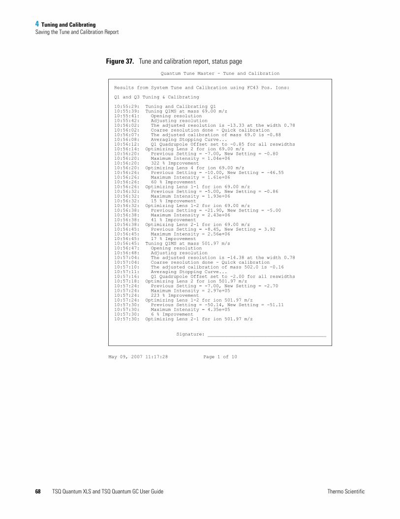
4 Tuning and CalibratingSaving the Tune and Calibration Report
Figure 37. Tune and calibration report, status page
Results from System Tune and Calibration using FC43 Pos. Ions:
Q1 and Q3 Tuning & Calibrating
10:55:29: Tuning and Calibrating Q110:55:39: Tuning Q1MS at mass 69.00 m/z10:55:41: Opening resolution10:55:42: Adjusting resolution10:56:02: The adjusted resolution is -13.33 at the width 0.7810:56:02: Coarse resolution done - Quick calibration10:56:07: The adjusted calibration of mass 69.0 is -0.8810:56:08: Averaging Stopping Curve...10:56:12: Q1 Quadrupole Offset set to -0.85 for all reswidths10:56:14: Optimizing Lens 2 for ion 69.00 m/z10:56:20: Previous Setting = -7.00, New Setting = -0.8010:56:20: Maximum Intensity = 1.04e+0610:56:20: 322 % Improvement10:56:20: Optimizing Lens 4 for ion 69.00 m/z10:56:26: Previous Setting = -10.00, New Setting = -46.5510:56:26: Maximum Intensity = 1.61e+0610:56:26: 60 % Improvement10:56:26: Optimizing Lens 1-1 for ion 69.00 m/z10:56:32: Previous Setting = -5.00, New Setting = -0.8610:56:32: Maximum Intensity = 1.93e+0610:56:32: 15 % Improvement10:56:32: Optimizing Lens 1-2 for ion 69.00 m/z10:56:38: Previous Setting = -21.90, New Setting = -5.0010:56:38: Maximum Intensity = 2.43e+0610:56:38: 41 % Improvement10:56:38: Optimizing Lens 2-1 for ion 69.00 m/z10:56:45: Previous Setting = -8.45, New Setting = 3.9210:56:45: Maximum Intensity = 2.56e+0610:56:45: 17 % Improvement10:56:45: Tuning Q1MS at mass 501.97 m/s10:56:47: Opening resolution10:56:48: Adjusting resolution10:57:04: The adjusted resolution is -14.38 at the width 0.7810:57:04: Coarse resolution done - Quick calibration10:57:10: The adjusted calibration of mass 502.0 is -0.1610:57:11: Averaging Stopping Curve...10:57:16: Q1 Quadrupole Offset set to -2.00 for all reswidths10:57:18: Optimizing Lens 2 for ion 501.97 m/z10:57:24: Previous Setting = -7.00, New Setting = -2.7010:57:24: Maximum Intensity = 2.97e+0510:57:24: 223 % Improvement10:57:24: Optimizing Lens 1-2 for ion 501.97 m/z10:57:30: Previous Setting = -50.14, New Setting = -51.1110:57:30: Maximum Intensity = 4.35e+0510:57:30: 6 % Improvement10:57:30: Optimizing Lens 2-1 for ion 501.97 m/z
Page 1 of 10May 09, 2007 11:17:28
Quantum Tune Master - Tune and Calibration
Signature: __________________________________________
68 TSQ Quantum XLS and TSQ Quantum GC User Guide Thermo Scientific

4 Tuning and CalibratingSaving the Tune and Calibration Report
Figure 38. Tune and calibration report, parameter optimization plots
To save the tune and calibration report
1. In the System Tune and Calibration dialog box, click Save Report. The Save As dialog box appears.
2. Enter the name and the path of the report, and click Save.
Optimizing Lens 2 for Q1MS
-50 -40 -30 -20 -10 0 Lens 2 Voltage (V)
0
20
40
60
80
100
ytis
net
nI e
vital
eR
May 9, 2007
Previous SettingOptimum Setting
Mass 69.00m/z : 322 % Improvement
Mass 501.97m/z : 223 % Improvement Mass 218.99m/z : 94 % Improvement
Optimizing Lens 2 for Q3MS
-50 -40 -30 -20 -10 0 Lens 2 Voltage (V)
0
20
40
60
80
100
ytis
net
nI e
vital
eR
May 9, 2007
Previous SettingOptimum Setting
Mass 69.00m/z : 235 % Improvement
Mass 501.97m/z : 281 % Improvement Mass 218.99m/z : 57 % Improvement
Optimizing Lens 4 for Q1MS
-50 -40 -30 -20 -10 0 Lens 4 Voltage (V)
0
20
40
60
80
100
ytis
net
nI e
vital
eR
May 9, 2007
Previous SettingOptimum Setting
Mass 69.00m/z : 60 % Improvement
Optimizing Lens 1-1 for Q1MS
-10 -8 -6 -4 -2 0 Lens 1-1 Voltage (V)
0
20
40
60
80
100
ytis
net
nI e
vital
eR
May 9, 2007
Previous SettingOptimum Setting
Mass 69.00m/z : 15 % Improvement
Optimizing Lens 1-1 for Q3MS
-10 -8 -6 -4 -2 0 Lens 1-1 Voltage (V)
0
20
40
60
80
100
ytis
net
nI e
vital
eR
May 9, 2007
Previous SettingOptimum Setting
Mass 69.00m/z : 6 % Improvement
Optimizing Lens 1-2 for Q1MS
-250 -200 -150 -100 -50 0 Lens 1-2 Voltage (V)
0
20
40
60
80
100
ytis
net
nI e
vital
eR
May 9, 2007
Previous SettingOptimum Setting
Mass 69.00m/z : 41 % Improvement
Mass 501.97m/z : 6 % Improvement Mass 218.99m/z : No Improvement
Quantum Tune Master - Tune and Calibration
Thermo Scientific TSQ Quantum XLS and TSQ Quantum GC User Guide 69

4 Tuning and CalibratingRunning Maintenance Tune
Running Maintenance TuneUse the maintenance tune procedure in EZ Tune to quickly increase the ion signal of the mass spectrometer. The maintenance tune adjusts the lens L1 voltage and the lens L11 offset voltage to maximize the ion signal for, for example, m/z 219 in FC-43 positive polarity mode. At the end of the procedure you can save the optimized lens L1 voltage to a tune file and the optimized lens L11 offset voltage to a calibration file.
Figure 39. Maintenance tune report, page 2
Optimizing Lens 1 for Q1MS
-45 -36 -27 -18 -9 0 Lens 1 Voltage (V)
0
20
40
60
80
100
Re
lati
ve
Inte
ns
ity
Feb 22, 2010
Previous SettingOptimum Setting
Mass 218.99m/z : 117 % Improvement
Optimizing Lens 1 for Q3MS
-45 -36 -27 -18 -9 0 Lens 1 Voltage (V)
0
20
40
60
80
100
Re
lati
ve
Inte
ns
ity
Feb 22, 2010
Previous SettingOptimum Setting
Mass 218.99m/z : 29 % Improvement
Optimizing Lens 1-1 for Q1MS
-15 -12 -10 -7 -5 -2 Lens 1-1 Voltage (V)
0
20
40
60
80
100
Re
lati
ve
Inte
ns
ity
Feb 22, 2010
Previous SettingOptimum Setting
Mass 218.99m/z : 94 % Improvement
Optimizing Lens 1-1 for Q3MS
-15 -12 -10 -7 -5 -2 Lens 1-1 Voltage (V)
0
20
40
60
80
100R
ela
tiv
e In
ten
sit
y
Feb 22, 2010
Previous SettingOptimum Setting
Mass 218.99m/z : 10 % Improvement
EIL1 DAC Scan #A: 19 Peak: -36.71; 1.36e+004
-45 -40 -35 -30 -25 -20 -15 -10 -5 0Parameter Setting (Arb)
0
10
20
30
40
50
60
70
80
90
100
Rel
ativ
e Ab
unda
nce
-36.71
-11.35-17.07
-3.65-30.00 -24.59
-9.37 -1.89-21.53
-33.83 -27.03
-41.71-38.92
L11 DAC Scan #A: 19 Peak: -2.69; 1.45e+004
-15 -14 -13 -12 -11 -10 -9 -8 -7 -6 -5 -4 -3 -2 -1 0Parameter Setting (Arb)
0
10
20
30
40
50
60
70
80
90
100
Rel
ativ
e Ab
unda
nce
-2.69-10.16
-4.76-7.61
-11.07 -8.34 -6.17
-3.76-13.42
70 TSQ Quantum XLS and TSQ Quantum GC User Guide Thermo Scientific

4 Tuning and CalibratingCreating a Quality Control (QC) Tune Report
To run maintenance tune
1. Display the FC-43 mass spectrum in positive or negative polarity mode as described in “Displaying the FC-43 Mass Spectrum” on page 62.
2. Click the System Tune and Calibration button (or choose Setup > System Tune and Calibration) to display the System Tune and Calibration dialog box. See Figure 35 on page 65.
3. Select the calibration compound
4. Click Start Main Tune to start the maintenance tune procedure.
5. After the procedure terminates you can accept the maintenance tune and save the calibration, or undo the tune.
Creating a Quality Control (QC) Tune ReportUse the TSQ QC (quality control) Report dialog box in EZ Tune to produce a report that displays tune parameters and mass spectra relevant to the performance of the mass spectrometer. You can save the report as a PDF file.
The TSQ QC tune report includes the following:
• Profile spectra of the three FC-43 peaks
• Setpoints and readbacks of the ion source lenses and L11 voltages
• Q1/MS full scan centroid spectrum from m/z 50 to 650
• FC-43 peak positions and intensity ratios
• Results of a leak check (pass or fail)
Figure 40 shows a TSQ QC tune report.
Thermo Scientific TSQ Quantum XLS and TSQ Quantum GC User Guide 71

4 Tuning and CalibratingCreating a Quality Control (QC) Tune Report
Figure 40. TSQ QC tune report
TSQ Quantum QC Tune ReportMar 04, 2010 13:49:00 TSQ Quantum Ultra S/N: TQU01196
Device SetPoint Readback
Lens 1 (V) -22.5 -22.3
Lens 2 (V) -180.0 -179.5
Lens 3 (V) -25.0 -25.0
Lens 4 (V) -31.1 -31.2
Lens 1-1 Offset (V) -3.1 -3.3
Emission Current (uA) 50 47
Electron Lens (V) 15 15
Electron Energy (eV) -70 -70
Source Temperature (C) 200 201
Ion Gauge Pressure (Torr) 4.8e-06
Q1 Peak Width(amu): 0.7
Air/Water Leak Check: PASS
qcr20100304134807 #1 ST: 3.02 uS: 1 NL: 8.65E7
68 70m/z
218 220m/z
500 502 504m/z
0
10
20
30
40
50
60
70
80
90
100R
elat
ive
Inte
nsity
0
10
20
30
40
50
60
70
80
90
100R
elat
ive
Inte
nsity
0
10
20
30
40
50
60
70
80
90
100R
elat
ive
Inte
nsity
68.889
219.021
500.457
501.865
qcr20100304134807 #11 ST: 1.03 uS: 1 NL: 9.75E7 + c EI Q1MS [46.500-700.500]
50 100 150 200 250 300 350 400 450 500 550 600 650m /z
0
10
20
30
40
50
60
70
80
90
100
Rel
ativ
e In
tens
ity
68.990219.002
130.982
263.993
99.982501.983413.986
168.985 463.984614.017313.995 375.983 538.000 664.002
Cal. Mass(m/z) Exact Mass(m/z) Intensity(cts) Ion Ratio(%)
68.990 68.995 97507088 103
219.002 218.986 94994288 100
501.983 501.971 12538017 13
Signature_____________________________ Date________________________
72 TSQ Quantum XLS and TSQ Quantum GC User Guide Thermo Scientific

4 Tuning and CalibratingCreating a Quality Control (QC) Tune Report
To create and save a QC tune report
1. Choose View > QC Report to open the TSQ QC Report dialog box.
2. Click Start to start the QC report procedure.
3. After the procedure terminates, click View Report to view the QC report as a PDF file.
4. Save the PDF file.
Thermo Scientific TSQ Quantum XLS and TSQ Quantum GC User Guide 73


5
Changing Ionization Modes
You can operate the TSQ Quantum XLS and TSQ Quantum GC mass spectrometers in either EI or CI ionization mode. Changing ionization modes requires changing ion volumes. You do not need to shut down the mass spectrometer to change ion volumes.
The following sections describe how to change the ionization mode.
Removing the Ion Volume
To remove the ion volume
1. Install the guide bar:
a. With the guide ball track facing left, insert the guide bar into the entry housing. See Figure 41.
b. Push the guide bar in as far as it will go; then, rotate it 90° clockwise to lock the guide bar in the entry housing.
Contents
• Removing the Ion Volume
• Installing the Ion Volume
Tools needed• Gloves, clean, lint- and powder-free• Insert/removal (I/R) tool and guide bar
Frequency When you change ionization modes or as needed to clean the ion volume
Thermo Scientific TSQ Quantum XLS and TSQ Quantum GC User Guide 75

5 Changing Ionization ModesRemoving the Ion Volume
Figure 41. Insertion/removal (I/R) tool and guide bar
2. Prepare the inlet valve and I/R tool for insertion:
a. Make sure the inlet valve is closed. Figure 42 shows the inlet valve lever is down for closed.
b. Loosen the inlet valve knob counterclockwise and remove the inlet valve plug. The inlet valve plug prevents air from entering the vacuum manifold in case the inlet valve is inadvertently opened.
c. Turn the I/R tool to the unlock position , which indicates the I/R tool is in position to accept the ion volume.
I/R tool
Guide ball hole
First stop
Guide ball track Guide bar
Bayonet lock
Guide ball
76 TSQ Quantum XLS and TSQ Quantum GC User Guide Thermo Scientific

5 Changing Ionization ModesRemoving the Ion Volume
Figure 42. Inlet valve components
3. Choose Start > All Programs > Thermo Instruments > TSQ > TSQ Tune to open the EZ Tune window.
4. Click the Probe button, , in the EZ Tune toolbar. The Insert Probe message appears (Figure 43).
Figure 43. Insert Probe message
5. Insert the I/R tool into the inlet valve:
a. Insert the guide ball into the guide ball hole.
b. Slide the I/R tool forward into the inlet valve until the guide ball is at the guide bar’s first stop (see Figure 44).
c. Tighten the inlet valve knob clockwise to ensure a leak-tight seal.
Inlet valve knob
Inlet valveplug
Entry housing
Inlet valve lever(down is closed, up is open)
Thermo Scientific TSQ Quantum XLS and TSQ Quantum GC User Guide 77
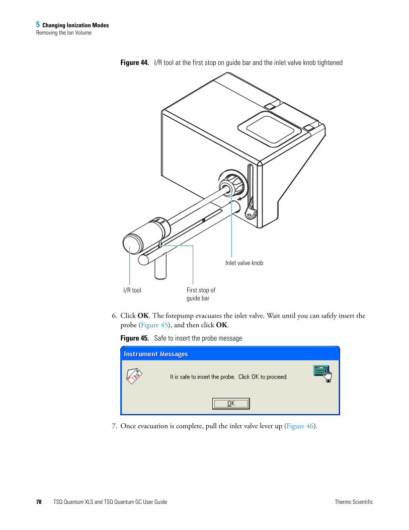
5 Changing Ionization ModesRemoving the Ion Volume
Figure 44. I/R tool at the first stop on guide bar and the inlet valve knob tightened
6. Click OK. The forepump evacuates the inlet valve. Wait until you can safely insert the probe (Figure 45), and then click OK.
Figure 45. Safe to insert the probe message
7. Once evacuation is complete, pull the inlet valve lever up (Figure 46).
Inlet valve knob
First stop of guide bar
I/R tool
78 TSQ Quantum XLS and TSQ Quantum GC User Guide Thermo Scientific
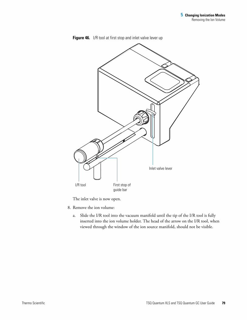
5 Changing Ionization ModesRemoving the Ion Volume
Figure 46. I/R tool at first stop and inlet valve lever up
The inlet valve is now open.
8. Remove the ion volume:
a. Slide the I/R tool into the vacuum manifold until the tip of the I/R tool is fully inserted into the ion volume holder. The head of the arrow on the I/R tool, when viewed through the window of the ion source manifold, should not be visible.
Inlet valve lever
First stop of guide bar
I/R tool
Thermo Scientific TSQ Quantum XLS and TSQ Quantum GC User Guide 79

5 Changing Ionization ModesRemoving the Ion Volume
Figure 47. I/R tool inserted into the inlet valve
b. Turn the I/R tool handle counterclockwise to put the I/R tool into lock position, . Listen for a click, which indicates that the handle is fully engaged in
the lock position and is holding the ion volume.
c. Withdraw the I/R tool (with the ion volume attached) until the guide ball reaches the first stop (see Figure 46).
d. Pull the lever down to close the inlet valve.
e. Loosen the inlet valve knob by turning it counterclockwise to release the seal.
f. Continue withdrawing the I/R tool completely from the inlet valve by sliding the I/R tool through the guide ball track in the guide bar.
I/R tool inserted into the vacuum manifold
CAUTION Do not withdraw the I/R tool beyond the point where the guide ball reaches the first stop in the guide bar. Close the inlet valve first. Otherwise, the system vents to the atmosphere.
80 TSQ Quantum XLS and TSQ Quantum GC User Guide Thermo Scientific
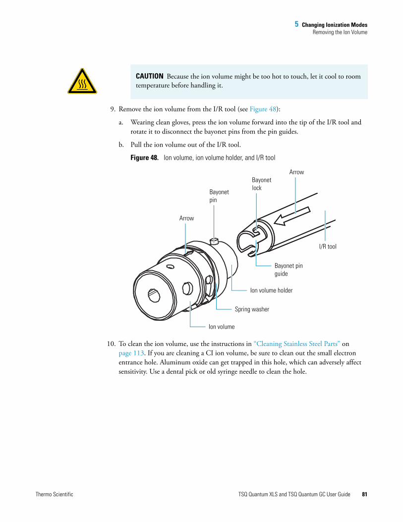
5 Changing Ionization ModesRemoving the Ion Volume
9. Remove the ion volume from the I/R tool (see Figure 48):
a. Wearing clean gloves, press the ion volume forward into the tip of the I/R tool and rotate it to disconnect the bayonet pins from the pin guides.
b. Pull the ion volume out of the I/R tool.
Figure 48. Ion volume, ion volume holder, and I/R tool
10. To clean the ion volume, use the instructions in “Cleaning Stainless Steel Parts” on page 113. If you are cleaning a CI ion volume, be sure to clean out the small electron entrance hole. Aluminum oxide can get trapped in this hole, which can adversely affect sensitivity. Use a dental pick or old syringe needle to clean the hole.
CAUTION Because the ion volume might be too hot to touch, let it cool to room temperature before handling it.
Arrow
Bayonetpin
Bayonetlock
Arrow
I/R tool
Bayonet pin guide
Ion volume holder
Spring washer
Ion volume
Thermo Scientific TSQ Quantum XLS and TSQ Quantum GC User Guide 81
5 Changing Ionization ModesInstalling the Ion Volume
Installing the Ion VolumeInstall an ion volume after cleaning or when you change ionization modes.
To install the ion volume
1. Place the clean ion volume on the I/R tool with the arrows aligned. See Figure 48.
2. Turn the I/R tool handle to the lock position, .
3. Install the guide bar:
a. With the guide ball track facing left, insert the guide bar into the entry housing (see Figure 41).
b. Push the guide bar in as far as it will go, and then rotate it 90° clockwise to lock the guide bar into the entry housing.
4. Prepare the inlet valve for insertion:
a. Make sure the inlet valve is closed. Figure 42 shows the inlet valve lever, closed in the down position.
b. Loosen the inlet valve knob counterclockwise and remove the inlet valve plug. The inlet valve plug prevents air from entering the vacuum manifold in case the inlet valve is inadvertently opened.
5. Choose Start > All Programs > Thermo Instruments > TSQ > TSQ Tune to open the EZ Tune window.
6. Click the Probe button, , in the EZ Tune toolbar. The Insert Probe message appears. See Figure 43.
7. Inset the I/R tool into the inlet valve:
a. Insert the guide ball into the guide ball hole.
b. Slide the I/R tool forward into the inlet valve until the guide ball is at the guide bar’s first stop. See Figure 44.
c. Tighten the inlet valve knob clockwise to ensure a leak-tight seal.
8. Click OK. The forepump evacuates the inlet valve. Wait until you can safely insert the probe (Figure 45); then click OK.
9. Once evacuation is complete, pull the inlet valve lever up to open the inlet valve.
Note Wear clean, lint- and powder- free gloves when you handle a clean ion volume.
CAUTION To avoid damage to the ion source, make sure to align the arrows on the I/R tool and ion volume.
82 TSQ Quantum XLS and TSQ Quantum GC User Guide Thermo Scientific
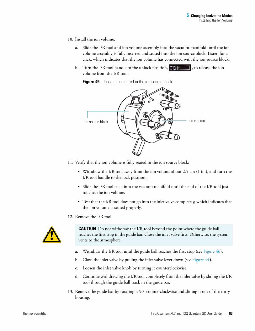
5 Changing Ionization ModesInstalling the Ion Volume
10. Install the ion volume:
a. Slide the I/R tool and ion volume assembly into the vacuum manifold until the ion volume assembly is fully inserted and seated into the ion source block. Listen for a click, which indicates that the ion volume has connected with the ion source block.
b. Turn the I/R tool handle to the unlock position, , to release the ion volume from the I/R tool.
Figure 49. Ion volume seated in the ion source block
11. Verify that the ion volume is fully seated in the ion source block:
• Withdraw the I/R tool away from the ion volume about 2.5 cm (1 in.), and turn the I/R tool handle to the lock position.
• Slide the I/R tool back into the vacuum manifold until the end of the I/R tool just touches the ion volume.
• Test that the I/R tool does not go into the inlet valve completely, which indicates that the ion volume is seated properly.
12. Remove the I/R tool:
a. Withdraw the I/R tool until the guide ball reaches the first stop (see Figure 46).
b. Close the inlet valve by pulling the inlet valve lever down (see Figure 44).
c. Loosen the inlet valve knob by turning it counterclockwise.
d. Continue withdrawing the I/R tool completely from the inlet valve by sliding the I/R tool through the guide ball track in the guide bar.
13. Remove the guide bar by rotating it 90° counterclockwise and sliding it out of the entry housing.
Ion source block Ion volume
CAUTION Do not withdraw the I/R tool beyond the point where the guide ball reaches the first stop in the guide bar. Close the inlet valve first. Otherwise, the system vents to the atmosphere.
Thermo Scientific TSQ Quantum XLS and TSQ Quantum GC User Guide 83
5 Changing Ionization ModesInstalling the Ion Volume
14. Replace the inlet valve plug. Orient the plug to indicate whether an EI or CI ion volume is installed.
15. Tighten the inlet valve knob clockwise to create a leak-tight seal.
16. (Optional) To prevent the inlet valve from being opened accidentally, pull free and remove the inlet valve lever.
84 TSQ Quantum XLS and TSQ Quantum GC User Guide Thermo Scientific

6
Maintenance
This chapter describes routine maintenance procedures that you must perform to ensure optimum performance of the TSQ Quantum XLS or TSQ Quantum GC mass spectrometer. Optimum performance of the mass spectrometer depends on the maintenance of all parts of the instrument. You are responsible for properly maintaining your instrument through regular performance of these maintenance procedures.
Table 6 lists routine and infrequent mass spectrometer maintenance procedures. For instructions on maintaining the GC or autosampler, refer to the manuals that come with the GC or autosampler.
Contents
• Cleaning Ion Source Components
• Replacing the Filament of the Ion Source
• Complete Disassembly and Reassembly of the Ion Source
• Maintaining the Forepump
• Adding Calibration Compound
• Replacing the Ball Valve Seal
• Removing and Installing a GC Capillary Column
Note When you perform maintenance procedures, be methodical; always wear clean, lint-free gloves when handling the components of the ion source; always place the components on a clean, lint-free surface; and never overtighten a screw or use excessive force.
Thermo Scientific TSQ Quantum XLS and TSQ Quantum GC User Guide 85

6 Maintenance
Table 6. Maintenance procedures (Sheet 1 of 2)
Mass spectrometer component Procedure Frequency Reference
Ion source Cleaning the ion volume
As needed* Page 90
Ion source Cleaning the lenses As needed* Page 90 (TSQ Quantum XLS),page 96 (TSQ Quantum GC)
Ion source Cleaning the entire ion source
As needed* Page 108 (TSQ Quantum XLS),page 110 (TSQ Quantum GC)
Ion source Replacing the filament If the filament fails Page 104 (TSQ Quantum XLS), page 106 (TSQ Quantum GC)
Inlet valve Replacing the ball valve seal
If there is an air leak in the inlet valve
Page 119
Calibration compound
Adding calibration compound
If EZ Tune error message indicates low intensity of calibration gas ions
Page 117
Gas chromatograph
Replacing the capillary column
If chromatographic separation is bad or if a different stationary phase is needed for the application
Page 121
Q0 ion optics Cleaning the Q0 quadrupole and L11 and L12 lenses**
As needed*
Mass analyzer Cleaning the Q1, Q2, and Q3 quadrupoles and lenses**
As needed*
Forepump Purging the forepump pump oil
If pump oil is cloudy Manufacturer’s documentation
Forepump Adding pump oil If pump oil level is low Manufacturer’s documentation
86 TSQ Quantum XLS and TSQ Quantum GC User Guide Thermo Scientific
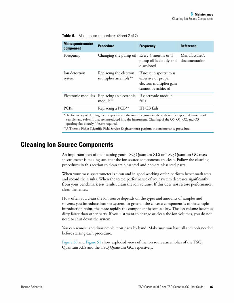
6 MaintenanceCleaning Ion Source Components
Cleaning Ion Source ComponentsAn important part of maintaining your TSQ Quantum XLS or TSQ Quantum GC mass spectrometer is making sure that the ion source components are clean. Follow the cleaning procedures in this section to clean stainless steel and non-stainless steel parts.
When your mass spectrometer is clean and in good working order, perform benchmark tests and record the results. When the tested performance of your system decreases significantly from your benchmark test results, clean the ion volume. If this does not restore performance, clean the lenses.
How often you clean the ion source depends on the types and amounts of samples and solvents you introduce into the system. In general, the closer a component is to the sample introduction point, the more rapidly the component becomes dirty. The ion volume becomes dirty faster than other parts. If you just want to change or clean the ion volumes, you do not need to shut down the system.
You can remove and disassemble most parts by hand. Make sure you have all the tools needed before starting each procedure.
Figure 50 and Figure 51 show exploded views of the ion source assemblies of the TSQ Quantum XLS and the TSQ Quantum GC, repectively.
Forepump Changing the pump oil Every 4 months or if pump oil is cloudy and discolored
Manufacturer’s documentation
Ion detection system
Replacing the electron multiplier assembly**
If noise in spectrum is excessive or proper electron multiplier gain cannot be achieved
Electronic modules Replacing an electronic module**
If electronic module fails
PCBs Replacing a PCB** If PCB fails
*The frequency of cleaning the components of the mass spectrometer depends on the types and amounts of samples and solvents that are introduced into the instrument. Cleaning of the Q0, Q1, Q2, and Q3 quadrupoles is rarely (if ever) required.
**A Thermo Fisher Scientific Field Service Engineer must perform this maintenance procedure.
Table 6. Maintenance procedures (Sheet 2 of 2)
Mass spectrometer component Procedure Frequency Reference
Thermo Scientific TSQ Quantum XLS and TSQ Quantum GC User Guide 87
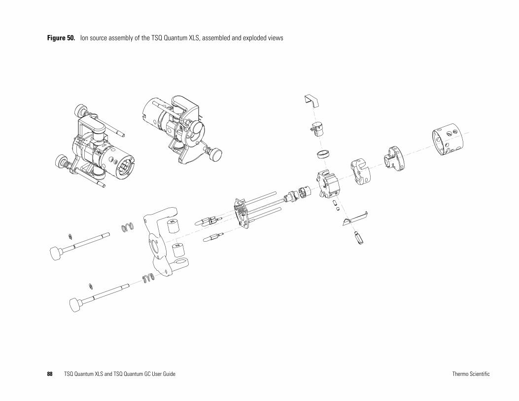
Thermo Scientific
Figure 50. Ion source assembly of the TSQ Quantum XLS, assembled and exploded views
88 TSQ Quantum XLS and TSQ Quantum GC User Guide

Thermo Scientific
Figure 51. Ion source assembly of the TSQ Quantum GC, exploded and assembled views
89 TSQ Quantum XLS and TSQ Quantum GC User Guide

6 MaintenanceCleaning Ion Source Components
Cleaning Ion Volumes
You do not need to vent the mass spectrometer to atmosphere to clean the ion volume.
To clean the ion volume
1. Remove the ion volume. See “Removing the Ion Volume” on page 75.
2. Clean the ion volume. See “Cleaning Stainless Steel Parts” on page 113. If you are cleaning a CI ion volume, be sure to clean out the small electron entrance hole. Aluminum oxide can get trapped in this hole, which can adversely affect sensitivity. Use a dental pick or old syringe needle to clean the hole.
3. Reinstall the ion volume. See“Installing the Ion Volume” on page 82.
Cleaning the Lenses of the TSQ Quantum XLS Ion Source
If cleaning the ion volume does not restore system performance, clean the ion source lenses.
To clean the ion source lenses
1. Shut down and vent the system. See “Shutting Down the System Completely” on page 51.
2. Remove the ion source. See “Removing the TSQ Quantum XLS Ion Source” on page 91.
3. Remove the ion source lens assemblies from the ion source and disassemble it. See “Removing the L1, L2, L3 Lens Assembly and the Heated Q0 Quadrupole Lens Assembly” on page 93.
4. Clean the lenses and the spacers. See “Cleaning Stainless Steel Parts” on page 113 and “Cleaning Non-Stainless Steel or Hybrid Parts” on page 115, respectively.
5. Reassemble L1, L2, L3 lens assembly and install it and the heated Q0 quadrupole onto the ion source. See “Reassembling the L1, L2, L3 Lens Assembly” on page 95.
CAUTION Burn Hazard. The ion volume might be hot. Allow the ion volume to cool to room temperature before touching it.
CAUTION Shock Hazard. Unplug the TSQ Quantum XLS mass spectrometer before proceeding.
CAUTION Burn Hazard. The ion source might be hot. Allow the ion source to cool to room temperature before touching it.
90 TSQ Quantum XLS and TSQ Quantum GC User Guide Thermo Scientific

6 MaintenanceCleaning Ion Source Components
6. Reinstall the ion source into the mass spectrometer and reinsert the capillary column into the ion source. See “Reinstalling the TSQ Quantum XLS Ion Source” on page 95.
7. Restart the system. See “Starting Up the System after a Complete Shutdown” on page 53.
Removing the TSQ Quantum XLS Ion Source
Remove the ion source to clean the lenses or replace the filament.
To remove the ion source
1. Shut down and vent the TSQ Quantum XLS mass spectrometer. See “Shutting Down the System Completely” on page 51.
2. Pull back the capillary column:
a. Lower the oven, injector, and transfer line temperatures to 30 °C and allow them to cool before continuing.
b. Once the oven, injector, and transfer line are cool, turn off the gas chromatograph.
c. Loosen the transfer line nut. See Figure 68 on page 122.
d. Pull back the column. (You can first mark the column’s position with white correction fluid or something similar.)
3. Prepare a clean work area by covering the area with lint-free cloth.
Tools needed• Gloves, cleanroom grade (P/N 23827-0008 and 23827-0009)• Lint-free cloth
Frequency As needed to perform ion source maintenance
CAUTION Do not remove the ion source without first pulling back the GC capillary column, or else the capillary column might break.
CAUTION Shock Hazard. Unplug the TSQ Quantum XLS mass spectrometer before proceeding.
CAUTION Burn Hazard. The GC oven, injector, and transfer line are hot. Allow them to cool to room temperature before touching them.
Thermo Scientific TSQ Quantum XLS and TSQ Quantum GC User Guide 91
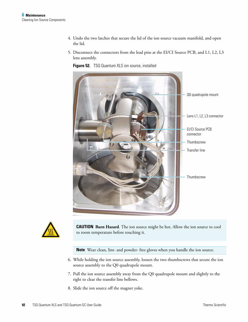
6 MaintenanceCleaning Ion Source Components
4. Undo the two latches that secure the lid of the ion source vacuum manifold, and open the lid.
5. Disconnect the connectors from the lead pins at the EI/CI Source PCB, and L1, L2, L3 lens assembly.
Figure 52. TSQ Quantum XLS ion source, installed
6. While holding the ion source assembly, loosen the two thumbscrews that secure the ion source assembly to the Q0 quadrupole mount.
7. Pull the ion source assembly away from the Q0 quadrupole mount and slightly to the right to clear the transfer line bellows.
8. Slide the ion source off the magnet yoke.
Q0 quadrupole mount
Lens L1, L2, L3 connector
EI/CI Source PCB connector
Transfer line
Thumbscrew
Thumbscrew
CAUTION Burn Hazard. The ion source might be hot. Allow the ion source to cool to room temperature before touching it.
Note Wear clean, lint- and powder- free gloves when you handle the ion source.
92 TSQ Quantum XLS and TSQ Quantum GC User Guide Thermo Scientific
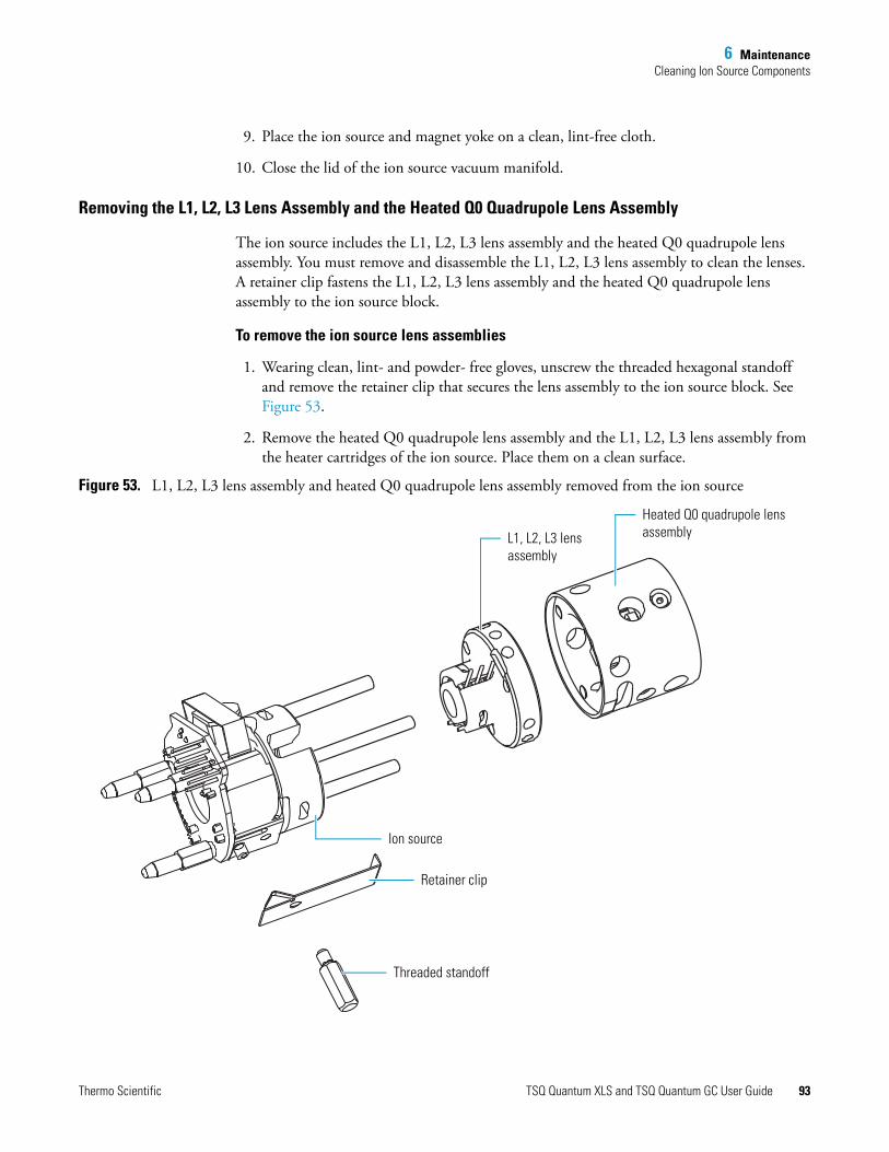
6 MaintenanceCleaning Ion Source Components
9. Place the ion source and magnet yoke on a clean, lint-free cloth.
10. Close the lid of the ion source vacuum manifold.
Removing the L1, L2, L3 Lens Assembly and the Heated Q0 Quadrupole Lens Assembly
The ion source includes the L1, L2, L3 lens assembly and the heated Q0 quadrupole lens assembly. You must remove and disassemble the L1, L2, L3 lens assembly to clean the lenses. A retainer clip fastens the L1, L2, L3 lens assembly and the heated Q0 quadrupole lens assembly to the ion source block.
To remove the ion source lens assemblies
1. Wearing clean, lint- and powder- free gloves, unscrew the threaded hexagonal standoff and remove the retainer clip that secures the lens assembly to the ion source block. See Figure 53.
2. Remove the heated Q0 quadrupole lens assembly and the L1, L2, L3 lens assembly from the heater cartridges of the ion source. Place them on a clean surface.
Figure 53. L1, L2, L3 lens assembly and heated Q0 quadrupole lens assembly removed from the ion source
L1, L2, L3 lens assembly
Heated Q0 quadrupole lens assembly
Retainer clip
Ion source
Threaded standoff
Thermo Scientific TSQ Quantum XLS and TSQ Quantum GC User Guide 93

6 MaintenanceCleaning Ion Source Components
Disassembling the L1, L2, L3 Lens Assembly
To disassemble the L1, L2, L3 lens assembly
1. Remove the lens retainer clip by pinching the ends with your fingers or a pair of tweezers. See Figure 54.
2. Remove the lenses and spacers from the lens holder.
3. Place the components on a clean surface.
Figure 54. L1, L2, L3 lens assembly, assembled and exploded views
Lens holder
Lens L3
Spacer
Lens L2
Spacer
Lens L1
Lens retainer clip
Note To clean the ion source lenses, follow the procedure in “Cleaning Stainless Steel Parts” on page 113. To clean the remaining parts, follow the procedure in “Cleaning Non-Stainless Steel or Hybrid Parts” on page 115.
94 TSQ Quantum XLS and TSQ Quantum GC User Guide Thermo Scientific
6 MaintenanceCleaning Ion Source Components
Reassembling the L1, L2, L3 Lens Assembly
Ensure that the lenses are clean and dry before you reassemble the lens assembly.
To reassemble the L1, L2, L3 lens assembly
1. Wearing clean, lint- and powder- free gloves, reinstall the lenses and spacers in the lens holder in the order and orientation shown in Figure 54, starting with lens L3.
2. Reinstall the lens clip by pinching the ends with your fingers or a pair of tweezers and seating it in the lens holder.
3. Insert the lens alignment tool (in the TSQ Quantum XLS Accessory Kit) into the lens assembly and align the lenses.
Reinstalling the Ion Source Lens Assemblies
To reinstall the ion source lens assemblies onto the ion source
1. Wearing clean, lint- and powder- free gloves, insert the three heater cartridges of the ion source through their corresponding holes in the L1, L2, L3 lens assembly. See Figure 53.
2. Insert the three heater cartridges of the ion source through their corresponding holes in the heated Q0 quadrupole lens assembly. Verify the correct orientation of the guide pin hole and the retainer clip groove on the heated Q0 quadrupole lens assembly.
3. Use the retainer clip and threaded standoff to secure the lens assemblies to the ion source.
Reinstalling the TSQ Quantum XLS Ion Source
To reinstall the ion source into the vacuum manifold
1. Wearing clean, lint- and powder- free gloves, place the ion source onto the magnet yoke.
2. Position the ion source in the vacuum manifold and ensure the following:
• The transfer line is seated in the sample inlet aperture in the ion source.
• The guide pin on the Q0 quadrupole mount inserts into the guide pin groove on the heated Q0 lens assembly.
• The two thumbscrews are aligned with the screw holes in the Q0 quadrupole mount. See Figure 52.
3. Secure the ion source to the Q0 quadrupole mount by alternately tightening each thumbscrew one-half turn at a time. Make sure there is no play in the ion source.
IMPORTANT For accurate temperature readings of the heater block, fully screw the threaded standoff into the ion source to ensure contact between the temperature sensor and the heater block.
Thermo Scientific TSQ Quantum XLS and TSQ Quantum GC User Guide 95

6 MaintenanceCleaning Ion Source Components
4. Align and reconnect the 8-pin connector to the lead pins on the EI/CI Source PCB. See Figure 52.
5. Align the 3-pin connector so that the side with the beveled edge is closest to the L3 lead pin and the side with the rounded corners is closest to the L1 lead pin.
6. Reconnect the 3-pin connector to the lead pins on the L1, L2, and L3 lenses. See Figure 52.
7. Reinsert the capillary column into the ion source:
a. Using the I/R tool, remove the ion volume. See “Removing the Ion Volume” on page 75.
b. Push the capillary column in until you can see it in the ion source.
c. Pull the column back just far enough that you cannot see it.
d. Tighten the transfer line nut and transfer line union.
e. Using the I/R tool, install the ion volume. See “Installing the Ion Volume” on page 82.
8. Close and secure the cover to the ion source vacuum manifold.
Cleaning the Lenses of the TSQ Quantum GC Ion Source
If cleaning the ion volume does not restore system performance, clean the ion source lenses.
To clean the ion source lenses
1. Shut down and vent the system. See “Shutting Down the System Completely” on page 49.
2. Remove the ion source. See “Removing the TSQ Quantum GC Ion Source” on page 97.
3. Remove the ion source lens assembly from the ion source and disassemble it. See “Removing the Ion Source Lens Assembly” on page 99.
Note Lens L4 requires cleaning less often than lens L1, L2, and L3.
CAUTION Shock Hazard. Unplug the TSQ Quantum GC mass spectrometer before proceeding.
CAUTION Burn Hazard. The ion source might be hot. Allow the ion source to cool to room temperature before touching it.
96 TSQ Quantum XLS and TSQ Quantum GC User Guide Thermo Scientific

6 MaintenanceCleaning Ion Source Components
4. Clean the lenses and the spacers. See “Cleaning Stainless Steel Parts” on page 113 and “Cleaning Non-Stainless Steel or Hybrid Parts” on page 115, respectively.
5. Reassemble the ion source lens assembly and install it onto the ion source. See “Reassembling the Ion Source Lens Assembly” on page 102.
6. Reinstall the ion source into the mass spectrometer and reinsert the capillary column into the ion source. See “Reinstalling theTSQ Quantum GC Ion Source” on page 103.
7. Restart the system. See “Starting Up the System after a Complete Shutdown” on page 51.
Removing the TSQ Quantum GC Ion Source
Remove the ion source to clean the lenses or replace the filament.
To remove the ion source
1. Shut down and vent the TSQ Quantum GC mass spectrometer. See “Shutting Down the System Completely” on page 49.
2. Pull back the capillary column:
a. Lower the oven, injector, and transfer line temperatures to 30 °C and allow them to cool before continuing.
b. Once the oven, injector, and transfer line are cool, turn off the gas chromatograph.
c. Loosen the transfer line nut. See Figure 68 on page 122.
Tools needed• Gloves, cleanroom grade (P/N 23827-0008 and 23827-0009)• Lint-free cloth
Frequency As needed to perform ion source maintenance
CAUTION Do not remove the ion source without first pulling back the capillary column, or else the capillary column might break.
CAUTION Shock Hazard. Unplug the TSQ Quantum GC mass spectrometer before proceeding.
CAUTION Burn Hazard. The GC oven, injector, and transfer line are hot. Allow them to cool to room temperature before touching them.
Thermo Scientific TSQ Quantum XLS and TSQ Quantum GC User Guide 97

6 MaintenanceCleaning Ion Source Components
d. Pull back the column. (You can first mark the column’s position with white correction fluid or something similar.)
3. Prepare a clean work area by covering the area with lint-free cloth.
4. Undo the two latches that secure the lid of the ion source vacuum manifold, and open the lid.
5. Disconnect the connectors from the lead pins at the EI/CI Source PCB, lens L1, L2, L3 assembly, and lens L4 assembly. See Figure 52.
Figure 55. TSQ Quantum GC ion source, installed
Q0 quadrupole mount
Lens L1, L2, L3 connector
EI/CI Source PCB connector
Transfer line
Thumbscrew
Thumbscrew
Lens L4 connector
CAUTION Burn Hazard. The ion source might be hot. Allow the ion source to cool to room temperature before touching it.
Note Wear clean, lint- and powder- free gloves when you handle the ion source.
98 TSQ Quantum XLS and TSQ Quantum GC User Guide Thermo Scientific

6 MaintenanceCleaning Ion Source Components
6. While holding the ion source assembly, loosen the two thumbscrews that secure the ion source assembly to the Q0 quadrupole mount.
7. Pull the ion source assembly away from the Q0 quadrupole mount and slightly to the right to clear the transfer line bellows.
8. Slide the ion source off the magnet yoke.
9. Place the ion source and magnet yoke on a clean, lint-free cloth.
10. Close the lid of the ion source vacuum manifold.
Removing the Ion Source Lens Assembly
The ion source lens assembly includes lens L1, L2, L3, and L4. You must remove and disassemble the ion source lens assembly to clean the lenses. A retainer clip fastens the lens assembly to the ion source block.
To remove the ion source lens assembly
1. Wearing clean, lint- and powder- free gloves, unscrew the threaded hexagonal standoff and remove the retainer clip that secures the lens assembly to the ion source block. See Figure 56.
2. Pull the lens assembly out of the ion source.
3. Place the ion source and lens assembly on a clean surface.
Figure 56. Lens assembly removed from the ion source
Lens assembly
Ion source
Retainer clip
Threaded standoff
Thermo Scientific TSQ Quantum XLS and TSQ Quantum GC User Guide 99
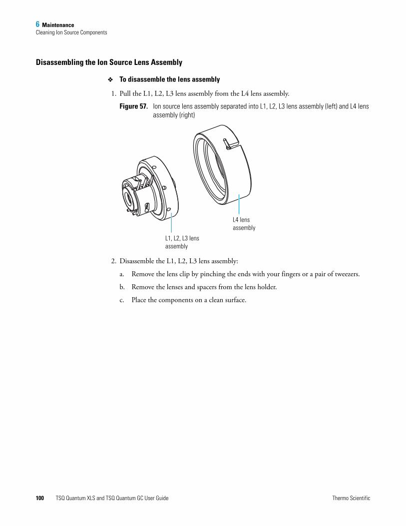
6 MaintenanceCleaning Ion Source Components
Disassembling the Ion Source Lens Assembly
To disassemble the lens assembly
1. Pull the L1, L2, L3 lens assembly from the L4 lens assembly.
Figure 57. Ion source lens assembly separated into L1, L2, L3 lens assembly (left) and L4 lens assembly (right)
2. Disassemble the L1, L2, L3 lens assembly:
a. Remove the lens clip by pinching the ends with your fingers or a pair of tweezers.
b. Remove the lenses and spacers from the lens holder.
c. Place the components on a clean surface.
L1, L2, L3 lens assembly
L4 lens assembly
100 TSQ Quantum XLS and TSQ Quantum GC User Guide Thermo Scientific

6 MaintenanceCleaning Ion Source Components
Figure 58. L1, L2, L3 lens assembly, exploded and assembled views
3. Disassemble the L4 lens assembly:
a. Remove the lens clip by pinching the ends with your fingers or a pair of tweezers.
b. Remove the lens L4 from the lens holder.
c. Place the components on a clean surface.
Lens holder
Lens L3
Spacer
Lens L2
Spacer
Lens L1
Lens retainer clip
Thermo Scientific TSQ Quantum XLS and TSQ Quantum GC User Guide 101

6 MaintenanceCleaning Ion Source Components
Figure 59. L4 lens assembly, exploded view
Reassembling the Ion Source Lens Assembly
Ensure that the lenses are clean and dry before you reassemble the lens assembly.
To reassemble the ion source lens assembly
1. Wearing clean, lint- and powder- free gloves, reassemble the L4 lens assembly.
a. Insert lens L4 into the lens holder. See Figure 59.
b. Install the lens clip by pinching the ends with your fingers or a pair of tweezers. Seat the lens clip in the lens holder.
2. Reassemble the L1, L2, L3 lens assembly. See Figure .
a. Reinstall the lenses and spacers in the lens holder in the order and orientation shown in Figure .
b. Reinstall the lens clip by pinching the ends with your fingers or a pair of tweezers and seating it in the lens holder.
c. Insert the lens alignment tool (in the TSQ Quantum GC Accessory Kit) into the lens assembly and align the lenses
3. Insert the L4 lens assembly into the L1, L2, L3 lens assembly. Align the lead pins. See Figure 57.
Note To clean the ion source lenses, follow the procedure in “Cleaning Stainless Steel Parts” on page 113.
Lens clip
Lens L4
Lens holder
102 TSQ Quantum XLS and TSQ Quantum GC User Guide Thermo Scientific

6 MaintenanceCleaning Ion Source Components
Reinstalling the Ion Source Lens Assembly
To reinstall the ion source lens assembly onto the ion source
1. Wearing clean, lint- and powder- free gloves, insert the lens assembly into the ion source. See Figure 57.
2. Use the retainer clip and threaded standoff to secure the lens assembly to the ion source. See Figure 56 on page 99.
Reinstalling theTSQ Quantum GC Ion Source
To reinstall the ion source into the vacuum manifold and insert the capillary column into the ion source
1. Wearing clean, lint- and powder- free gloves, place the ion source onto the magnet yoke.
2. Position the ion source in the vacuum manifold and ensure the following:
• The transfer line is seated in the sample inlet aperture in the ion source.
• The two thumbscrews are aligned with the screw holes in the Q0 quadrupole mount. See Figure 55.
3. Secure the ion source to the Q0 quadrupole mount by alternately tightening each thumbscrew one-half turn at a time. Make sure there is no play in the ion source.
4. Reconnect the connectors to the lead pins on the EI/CI Source PCB, lens L1, L2, L3 assembly (the orientation is not important), and lens L4 assembly. See Figure 52.
5. Reinsert the capillary column into the ion source:
a. Using the I/R tool, remove the ion volume. See “Removing the Ion Volume” on page 69.
b. Push the column in until you can see it through the inlet valve.
c. Pull the column back just far enough that you cannot see it.
d. Tighten the transfer line nut and transfer line union.
e. Using the I/R tool, install the ion volume. See “Installing the Ion Volume” on page 76.
6. Close and secure the cover to the ion source vacuum manifold.
IMPORTANT For accurate temperature readings of the heater block, fully screw the threaded standoff into the ion source to ensure contact between the temperature sensor and the heater block.
Thermo Scientific TSQ Quantum XLS and TSQ Quantum GC User Guide 103
6 MaintenanceReplacing the Filament of the Ion Source
Replacing the Filament of the Ion SourceThe number of ions produced in the ion source is approximately proportional to the filament emission current. If ion production is lacking, you might have to replace the filament. If the measured emission current is substantially less than the value that the emission current is set to, or if the measured emission current decreases over time, then the filament has failed or is failing and requires replacement.
Replacing the Filament of the TSQ Quantum XLS Ion Source
For the location of the ion source components, see Figure 50 on page 88 and Figure 60 on page page 105.
To replace the filament of the TSQ Quantum XLS ion source
1. Prepare a clean work area by covering the area with lint-free cloth.
2. Shut down and vent the TSQ Quantum XLS mass spectrometer. See “Shutting Down the System Completely” on page 51.
3. Remove the ion source. See “Removing the TSQ Quantum XLS Ion Source” on page 91.
4. Wearing clean, lint- and powder- free gloves, remove the ion source from the magnet yoke.
Tools needed• Filament (P/N 120320-0030)• Gloves, cleanroom grade (P/N 23827-0008 and 23827-0009)• Lint-free cloth
Frequency If filament fails
CAUTION Shock Hazard. Unplug the TSQ Quantum XLS mass spectrometer before proceeding.
104 TSQ Quantum XLS and TSQ Quantum GC User Guide Thermo Scientific

6 MaintenanceReplacing the Filament of the Ion Source
Figure 60. Disassembling the TSQ Quantum XLS ion source to replace the filament
5. Unscrew the threaded standoff and remove the retainer clip that secures the heater ring and lens assemblies to the ion source block. See Figure 60.
6. Pull the heater ring and lens assemblies off of the cartridge heaters on the ion source block. Place them on a clean surface.
7. Remove the retainer clip that secures the filament and centering ring to the ion source block.
8. Remove the filament and centering ring from the ion source block.
9. Inspect and install a new filament (P/N 120320-0030, in the TSQ Quantum XLS Accessory Kit):
a. Verify that the filament wire is centered in the electron lens hole.
b. Insert the filament into the centering ring.
Tip Now is a good time to clean the ion source block and lenses. To do so, use the procedure described in “Cleaning Stainless Steel Parts” on page 113.
Heater ring and lens assemblies
Centering ring
Heater ring and lens assemblies retainer clip
Threaded standoff
Filament retainer clip
Filament
Ion source block and EI/CI Source PCB
Thermo Scientific TSQ Quantum XLS and TSQ Quantum GC User Guide 105

6 MaintenanceReplacing the Filament of the Ion Source
c. Align the filament leads with the EI/CI Source PCB connectors and gently press the leads into the connectors. Normally, there is a small gap of about 0.4 mm (0.016 in.) between the filament and the connectors. The gap allows the ceramic centering ring to properly position and align the electron lens hole with the ion volume.
d. Secure the filament and centering ring with the retainer clip.
10. Press the heater ring and lens assemblies onto the cartridge heaters on the ion source block.
11. Use the retainer clip and threaded standoff to secure the lens assemblies to the ion source.
12. Reinstall the ion source onto the magnet yoke.
13. Reinstall the ion source into the vacuum manifold and reinsert the capillary column into the ion source. See “Reinstalling the TSQ Quantum XLS Ion Source” on page 95.
Restart the system. See “Starting Up the System after a Complete Shutdown” on page 53.
Replacing the Filament of the TSQ Quantum GC Ion Source
See Figure 51 on page 89 and Figure 61 for the location of the ion source components.
To replace the ion source filament of the TSQ Quantum GC ion source
1. Prepare a clean work area by covering the area with lint-free cloth.
2. Shut down and vent the TSQ Quantum GC mass spectrometer. See “Shutting Down the System Completely” on page 49.
3. Remove the ion source. See “Removing the TSQ Quantum GC Ion Source” on page 97.
4. Wearing clean, lint- and powder- free gloves, remove the ion source from the magnet yoke.
IMPORTANT For accurate temperature readings of the heater block, fully screw the threaded standoff into the ion source to ensure contact between the temperature sensor and the heater block.
CAUTION Shock Hazard. Unplug the TSQ Quantum GC mass spectrometer before proceeding.
106 TSQ Quantum XLS and TSQ Quantum GC User Guide Thermo Scientific

6 MaintenanceReplacing the Filament of the Ion Source
Figure 61. Disassembling the ion source to replace the filament
5. Unscrew the threaded standoff and remove the retainer clip that secures the heater ring and lens assembly to the ion source block. See Figure 60.
6. Pull the heater ring and lens assembly out of the ion source block.
7. Remove the retainer clip that secures the filament and centering ring to the ion source block.
8. Remove the filament and centering ring from the ion source block.
9. Inspect and install a new filament (P/N 120320-0030, in the TSQ Quantum GC Accessory Kit):
a. Verify that the filament wire is centered in the electron lens hole.
b. Insert the filament into the centering ring.
c. Seat the filament on the EI/CI Source PCB.
d. Secure the filament with the retainer clip.
Note Now is a good time to clean the ion source block. To do so, use the procedure described in “Cleaning Stainless Steel Parts” on page 113.
Heater ring and lens assembly
Centering ring
Heater ring and lens assembly retainer clip
Threaded standoff
Filament retainer clip
Filament
Ion source block and EI/CI Source PCB
Thermo Scientific TSQ Quantum XLS and TSQ Quantum GC User Guide 107

6 MaintenanceComplete Disassembly and Reassembly of the Ion Source
10. Press the heater ring and lens assembly onto the ion source block.
11. Use the retainer clip and threaded standoff to secure the lens assembly to the ion source. See Figure 60.
12. Reinstall the ion source onto the magnet yoke.
13. Reinstall the ion source into the vacuum manifold and reinsert the capillary column into the ion source. See “Reinstalling the TSQ Quantum XLS Ion Source” on page 95.
14. Restart the system. See “Starting Up the System after a Complete Shutdown” on page 51.
Complete Disassembly and Reassembly of the Ion Source Disassemble the ion source completely to clean the ion source block or to replace the EI/CI Source PCB.
Complete Disassembly and Reassembly of the TSQ Quantum XLS Ion Source
See Figure 62 for the location of the ion source components.
To disassemble the TSQ Quantum XLS ion source completely
1. Prepare a clean work area by covering the area with lint-free cloth.
2. Shut down and vent the TSQ Quantum XLS. See“Shutting Down the System Completely” on page 51.
3. Wearing clean, lint- and powder- free gloves, remove the ion source. See “Removing the TSQ Quantum XLS Ion Source” on page 91.
4. Remove the ion source from the magnet yoke.
IMPORTANT For accurate temperature readings of the heater block, fully screw the threaded standoff into the ion source to ensure contact between the temperature sensor and the heater block.
Tools Needed• Gloves, cleanroom grade (P/N 23827-0008 and 23827-0009)• Lint-free cloth
Frequency As needed
CAUTION Shock Hazard. Unplug the TSQ Quantum XLS mass spectrometer before proceeding.
108 TSQ Quantum XLS and TSQ Quantum GC User Guide Thermo Scientific

6 MaintenanceComplete Disassembly and Reassembly of the Ion Source
Figure 62. TSQ Quantum XLS ion source, disassembled
5. Unscrew the threaded hexagonal standoff and remove the retainer clip that secures the heater ring and lens assemblies to the ion source block.
6. Pull the heated Q0 quadrupole lens assembly and the L1, L2, L3 lens assembly off the ion source.
7. Pull the heater ring off the ion source.
8. Unscrew and remove the three base studs.
9. Remove the EI/CI Source PCB:
a. Place the ion source on a clean surface with the cartridge heaters down and the EI/CI Source PCB up.
b. Press down on the ion source block to separate it from the EI/CI Source PCB.
10. Remove the retainer clip that secures the filament and centering ring to the ion source block.
L1, L2, L3 lens assembly
Heated Q0 quadrupole lens assembly
Filament retainer clip
Filament
Heater ringCentering ring
Ion source block
Heater ring and lens assemblies retainer clip
Threaded standoff
Ion volume retaining thumbscrew
EI/CI Source PCB
Base studs
CAUTION To prevent damage, do not pull the EI/CI Source PCB out of the ion source block.
Thermo Scientific TSQ Quantum XLS and TSQ Quantum GC User Guide 109

6 MaintenanceComplete Disassembly and Reassembly of the Ion Source
11. Remove the filament and centering ring from the ion source block.
12. Clean the ion source block and lenses. See “Cleaning Stainless Steel Parts” on page 113. Clean non-stainless steel parts as described in “Cleaning Non-Stainless Steel or Hybrid Parts” on page 115.
To reassemble the ion source
1. Reinstall the EI/CI Source PCB:
a. Align and insert the cartridge heaters and temperature sensor on the EI/CI Source PCB with the corresponding holes in the ion source block.
b. Reinstall the three base studs.
2. Reinstall the filament and centering ring:
a. Insert the filament into the centering ring.
b. Align the filament leads with the EI/CI Source PCB connectors and gently press the leads into the connectors. Normally, there is a small gap of about 0.4 mm (0.016 in.) between the filament and the connectors. The gap allows the ceramic centering ring to properly position and align the electron lens hole with the ion volume.
c. Secure the filament and centering ring with the retainer clip.
3. Press the heater ring and lens assemblies onto the ion source block.
4. Use the retainer clip and threaded standoff to secure the heater ring lens assembly to the ion source. See Figure 62.
5. Reinstall the ion source into the vacuum manifold and reinsert the capillary column into the ion source. See “Reinstalling the TSQ Quantum XLS Ion Source” on page 95.
6. Restart the system. See “Starting Up the System after a Complete Shutdown” on page 53.
Complete Disassembly and Reassembly of the TSQ Quantum GC Ion Source
Disassemble the ion source completely to clean the ion source block or replace the EI/CI Source PCB.
See Figure 63 for the location of the ion source components.
IMPORTANT Ensure that the temperature sensor is seated snugly.
IMPORTANT For accurate temperature readings of the heater block, fully screw the threaded standoff into the ion source to ensure contact between the temperature sensor and the heater block.
110 TSQ Quantum XLS and TSQ Quantum GC User Guide Thermo Scientific
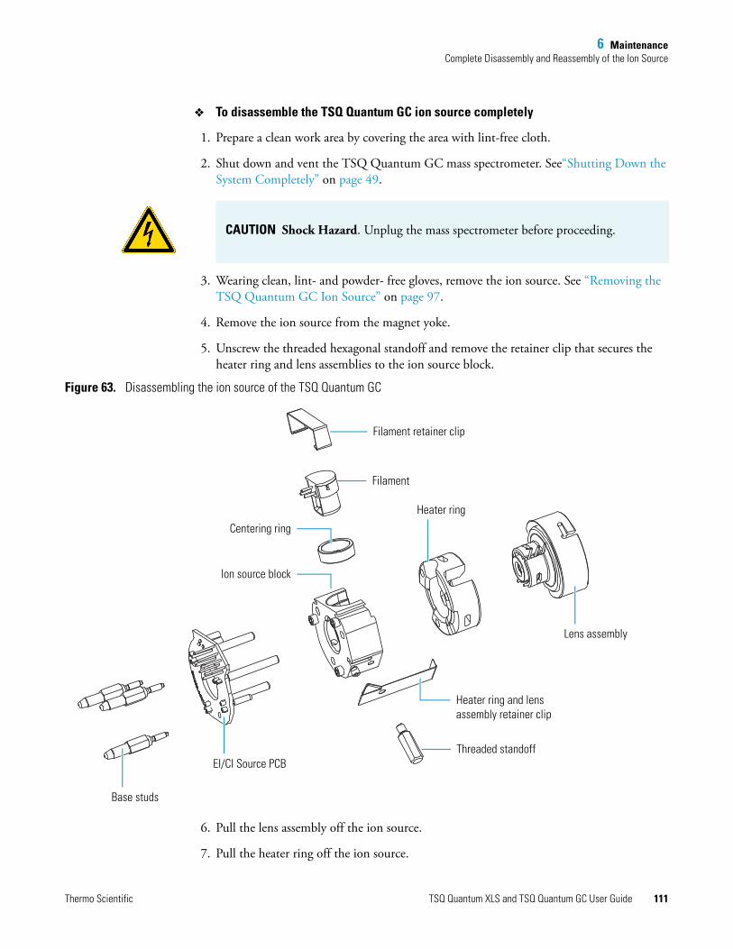
6 MaintenanceComplete Disassembly and Reassembly of the Ion Source
To disassemble the TSQ Quantum GC ion source completely
1. Prepare a clean work area by covering the area with lint-free cloth.
2. Shut down and vent the TSQ Quantum GC mass spectrometer. See“Shutting Down the System Completely” on page 49.
3. Wearing clean, lint- and powder- free gloves, remove the ion source. See “Removing the TSQ Quantum GC Ion Source” on page 97.
4. Remove the ion source from the magnet yoke.
5. Unscrew the threaded hexagonal standoff and remove the retainer clip that secures the heater ring and lens assemblies to the ion source block.
Figure 63. Disassembling the ion source of the TSQ Quantum GC
6. Pull the lens assembly off the ion source.
7. Pull the heater ring off the ion source.
CAUTION Shock Hazard. Unplug the mass spectrometer before proceeding.
Lens assembly
Filament retainer clip
Filament
Heater ring
Centering ring
Ion source block
Heater ring and lens assembly retainer clip
EI/CI Source PCB
Base studs
Threaded standoff
Thermo Scientific TSQ Quantum XLS and TSQ Quantum GC User Guide 111
6 MaintenanceComplete Disassembly and Reassembly of the Ion Source
8. Unscrew and remove the three base studs.
9. Remove the EI/CI Source PCB:
a. Place the ion source on a clean surface with the cartridge heaters down and the EI/CI Source PCB up.
b. Press down on the ion source block to separate it from the EI/CI Source PCB.
10. Remove the retainer clip that secures the filament and centering ring to the ion source block.
11. Remove the filament and centering ring from the ion source block.
12. Clean the ion source block and lenses. See “Cleaning Stainless Steel Parts” on page 113. Clean non-stainless steel parts as described in “Cleaning Non-Stainless Steel or Hybrid Parts” on page 115.
To reassemble the ion source
1. Reinstall the EI/CI Source PCB:
a. Align and insert the cartridge heaters and temperature sensor on the EI/CI Source PCB with the corresponding holes in the ion source block.
b. Reinstall the three base studs.
2. Reinstall the filament and centering ring:
a. Insert the filament into the centering ring.
b. Align the filament leads with the EI/CI Source PCB connectors and gently press the leads into the connectors. Normally, there is a small gap of about 0.4 mm (0.016 in.) between the filament and the connectors. The gap allows the ceramic centering ring to properly position and align the electron lens hole with the ion volume.
c. Secure the filament and centering ring with the retainer clip.
3. Press the heater ring and lens assembly onto the ion source block.
4. Use the retainer clip and threaded standoff to secure the heater ring and lens assembly to the ion source. See Figure 63.
CAUTION To prevent damage, do not pull the EI/CI Source PCB out of the ion source block.
IMPORTANT Ensure that the temperature sensor is seated snugly.
IMPORTANT For accurate temperature readings of the heater block, fully screw the threaded standoff into the ion source to ensure contact between the temperature sensor and the heater block.
112 TSQ Quantum XLS and TSQ Quantum GC User Guide Thermo Scientific

6 MaintenanceComplete Disassembly and Reassembly of the Ion Source
5. Reinstall the ion source into the vacuum manifold and insert the capillary column into the ion source. See “Reinstalling theTSQ Quantum GC Ion Source” on page 103.
6. Restart the system. See “Starting Up the System after a Complete Shutdown” on page 51.
Cleaning Stainless Steel Parts
To clean stainless-steel parts
1. Remove contamination from all the surfaces you are cleaning:
a. Use a slurry of number 600 aluminum oxide in glycerol and a cleaning brush or cotton-tipped applicator. Contamination appears as dark or discolored areas, but often is not visible. The heaviest contamination is usually found around the apertures, such as the electron entrance hole on an ion volume.
b. Clean each part thoroughly, even if no contamination is visible.
c. To clean the inside corners, use the wooden end of an applicator cut at an angle.
Tools needed• Acetone, reagent grade (or other suitable polar solvent)• Aluminum oxide abrasive, number 600 (P/N 32000-60340)• Applicators, cotton-tipped (P/N 00301-01-00015)• Beaker, 450 mL• Clean, dry gas• Deionized water• Detergent (Alconox™, Micro, or equivalent)• Dremel™ rotary tool or equivalent (recommended)• Foil, aluminum• Forceps (P/N 76360-0400)• Gloves, cleanroom grade (P/N 23827-0008 and 23827-0009)• Glycerol, reagent grade• Lint-free cloth• Protective eyewear• Tap water• Toothbrush, soft• Ultrasonic cleaner
Frequency As needed to clean these stainless steel parts:
• Ion volumes• Ion source block• Ion source lenses
CAUTION Material and Eye Hazard. Wear impermeable laboratory gloves and eye protection when performing cleaning procedures.
Thermo Scientific TSQ Quantum XLS and TSQ Quantum GC User Guide 113
6 MaintenanceComplete Disassembly and Reassembly of the Ion Source
d. Use a Dremel tool with the polishing swab at its lowest speed. This will increase cleaning efficiency as well as decrease the time required to clean the items.
2. Rinse the parts with clean water. Use a clean applicator or toothbrush to remove the aluminum oxide slurry. Do not let the slurry dry on the metal; dried aluminum oxide is difficult to remove.
3. Sonicate the parts in a warm detergent solution:
a. Using forceps, place the parts in a beaker containing warm detergent solution.
b. Place the beaker and contents in an ultrasonic bath for five minutes.
c. Rinse the parts with tap water to remove the detergent.
4. Sonicate the parts in deionized water:
a. Using forceps, place the parts in a beaker containing deionized water.
b. Place the beaker and contents in an ultrasonic bath for five minutes.
c. If the water is cloudy after sonicating, pour off the water, add fresh water, and place the beaker and its contents in an ultrasonic bath again for five minutes. Repeat until the water is clear.
5. Sonicate the parts in acetone:
a. Using forceps, place the parts in a beaker containing acetone.
b. Using forceps, transfer the parts to a beaker containing fresh acetone.
c. Place the beaker and contents in an ultrasonic bath again for five minutes.
6. Blow-dry the parts immediately. Use clean, dry gas to blow the acetone off the parts.
7. Using forceps, place the parts in a beaker, cover the beaker with aluminum foil, and put the beaker in the oven.
8. Dry the parts in an oven set at 100 oC for 30 minutes.
9. Allow the parts to cool before putting them back together.
CAUTION To prevent personal injury, be sure to keep the Dremel tool away from possible hazards, such as standing water or flammable solvents.
114 TSQ Quantum XLS and TSQ Quantum GC User Guide Thermo Scientific

6 MaintenanceComplete Disassembly and Reassembly of the Ion Source
Cleaning Non-Stainless Steel or Hybrid Parts
To clean non-stainless steel or hybrid parts
1. Remove contamination from stainless steel surfaces. You only need to clean a surface that comes in contact with the ion beam.
a. Use a slurry of number 600 aluminum oxide in glycerol and a cleaning brush or cotton-tipped applicator.
b. Clean each part thoroughly, even if no contamination is visible.
c. To clean the inside corners, use the wooden end of an applicator cut at an angle.
d. Use a Dremel tool with the polishing swab at its lowest speed. This will increase cleaning efficiency as well as decrease the time required to clean the items.
Tools needed• Acetone, reagent grade (or other suitable polar solvent)• Aluminum oxide abrasive, number 600 (P/N 32000-60340)• Applicators, cotton-tipped (P/N 00301-01-00015)• Beaker, 450 mL• Clean, dry gas• Deionized water• Detergent (Alconox, Micro, or equivalent)• Dremel rotary tool or equivalent (recommended)• Forceps (P/N 76360-0400)• Gloves, cleanroom grade (P/N 23827-0008 and 23827-0009)• Glycerol, reagent grade• Lint-free cloth• Protective eyewear• Tap water• Toothbrush, soft
Frequency As needed to clean non-stainless steel parts (such as aluminum, ceramic, or gold plated), or to clean hybrid parts that are partially made of stainless steel:
• Lens holder and spacers• Filament spacer• Heater ring
CAUTION Material and Eye Hazard. Wear impermeable laboratory gloves and eye protection when performing cleaning procedures.
Note Contamination appears as dark or discolored areas, but often is not visible.
Thermo Scientific TSQ Quantum XLS and TSQ Quantum GC User Guide 115

6 MaintenanceMaintaining the Forepump
e. Rinse the parts with clean water. Use a clean applicator or toothbrush to remove the aluminum oxide slurry. Do not let the slurry dry on the metal; dried aluminum oxide is difficult to remove.
2. Scrub all of the parts with a warm detergent solution:
a. Scrub the parts with a toothbrush or clean applicator. Do not soak or sonicate the parts in detergent.
b. Using forceps, rinse the parts thoroughly with tap water to remove the detergent.
3. Rinse the parts in deionized water.
Using forceps, dip the parts in a beaker of deionized water. Change the water if it becomes cloudy. Do not soak or sonicate the parts.
4. Rinse the parts with acetone. Using forceps, dip the parts in a beaker of acetone. Change the acetone if it becomes cloudy. Do not soak or sonicate the parts.
5. Blow-dry the parts immediately. Use clean, dry gas to blow the acetone off the parts.
Maintaining the ForepumpInspecting, adding, purging, and changing the forepump oil are all that is required to maintain the forepump.
Forepump oil is a translucent, light amber color, which you must check often. During normal operation, oil must always be visible in the oil level sight glass between the MIN and MAX marks. If the oil level is below the MIN mark, add oil. If the oil is cloudy or discolored, purge the oil to decontaminate dissolved solvents. If the pump oil is still discolored, change it. Plan to change the pump oil every 3000 hours (about four months) of operation. Refer to the manufacturer’s documentation for procedures for purging, adding, and changing the forepump oil.
CAUTION To prevent personal injury, be sure to keep the tool away from possible hazards, such as standing water or flammable solvents.
CAUTION Do not leave aluminum parts, such as the heater ring, in the detergent. Basic solutions, like detergent, discolor aluminum.
CAUTION If you use ammonia as a chemical ionization reagent gas, change the oil every month. Ammonia is highly basic and quickly damages seals in the forepump. Purging the oil with the Gas Ballast Control helps remove dissolved ammonia from the oil.
116 TSQ Quantum XLS and TSQ Quantum GC User Guide Thermo Scientific

6 MaintenanceAdding Calibration Compound
Adding Calibration Compound
The calibration compound is a liquid whose mass spectrum of ions is used to tune and calibrate the TSQ Quantum XLS and TSQ Quantum GC mass spectrometers. The mass spectrometers use FC-43 as their calibration compound. Although you cannot visually determine when to add a calibration compound, Xcalibur Automatic Tune produces an error message, stating: “the intensity of calibration gas ions is too low.” This message indicates that you must add calibration compound. However, there are many factors other than a decrease in the calibration compound that can cause a shortage of calibration gas ions. As a rule, add calibration compound once a year.
To add calibration compound
1. In EZ Tune, place the instrument in standby.
2. Remove the cover to the calibration compound vial compartment. See Figure 64.
Figure 64. Location of the calibration compound vial compartment
Tools needed• Calibration compound (P/N 50010-02500)• Syringe (P/N 36502019)
Frequency Yearly or as needed
Calibration compound vial compartment
Thermo Scientific TSQ Quantum XLS and TSQ Quantum GC User Guide 117
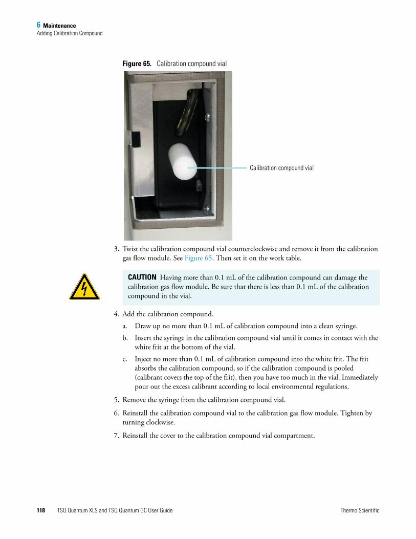
6 MaintenanceAdding Calibration Compound
Figure 65. Calibration compound vial
3. Twist the calibration compound vial counterclockwise and remove it from the calibration gas flow module. See Figure 65. Then set it on the work table.
4. Add the calibration compound.
a. Draw up no more than 0.1 mL of calibration compound into a clean syringe.
b. Insert the syringe in the calibration compound vial until it comes in contact with the white frit at the bottom of the vial.
c. Inject no more than 0.1 mL of calibration compound into the white frit. The frit absorbs the calibration compound, so if the calibration compound is pooled (calibrant covers the top of the frit), then you have too much in the vial. Immediately pour out the excess calibrant according to local environmental regulations.
5. Remove the syringe from the calibration compound vial.
6. Reinstall the calibration compound vial to the calibration gas flow module. Tighten by turning clockwise.
7. Reinstall the cover to the calibration compound vial compartment.
Calibration compound vial
CAUTION Having more than 0.1 mL of the calibration compound can damage the calibration gas flow module. Be sure that there is less than 0.1 mL of the calibration compound in the vial.
118 TSQ Quantum XLS and TSQ Quantum GC User Guide Thermo Scientific

6 MaintenanceReplacing the Ball Valve Seal
Replacing the Ball Valve Seal
The ball valve seal in the inlet valve can become worn over time. Replace the ball valve seal if it leaks air after you insert the direct insertion probe or I/R tool and tighten the inlet valve knob. The ball valve seal kit (P/N 119265-0003) is included in the Accessory Kit.
The ball valve seal consists of a Teflon™ spool and two O-rings. See Figure 66.
Figure 66. Components of the ball valve seal and inlet valve
You use the ball valve seal extraction tool (part of the Ball Valve Seal Kit, P/N 119265-0003) to remove the ball valve seal. See Figure 67.
Tools needed• Ball valve seal kit (P/N 119265-0003)
Frequency If the ball valve seal leaks air after you insert the direct insertion probe or I/R tool into the inlet valve and tighten the inlet valve knob
Ball valve seal components
Inlet valve insert
Inlet valve knob
Inlet valve housing
Thermo Scientific TSQ Quantum XLS and TSQ Quantum GC User Guide 119

6 MaintenanceReplacing the Ball Valve Seal
To remove the ball valve seal
1. Loosen the inlet valve knob counterclockwise until you can remove it.
2. Remove the inlet valve knob, plug, and insert.
3. Insert the not-engaged ball valve seal extraction tool into the inlet valve housing.
4. Engage the ball valve seal by pushing the plunger of the ball valve seal extraction tool forward.
5. Remove the seal and tool.
6. Pull the plunger back to disengage the seal.
Figure 67. Ball valve seal extraction tool and ball valve seal, not engaged (left) and engaged (right)
To install the ball valve seal
1. Obtain the Ball Valve Seal Kit (P/N 119265-0003) from the Accessory Kit.
2. Assemble the ball valve seal by installing the two O-rings onto the Teflon spool.
3. Insert the ball valve seal into the ball valve manifold with your finger.
4. Install the inlet valve knob and insert.
5. Install the inlet valve plug and tighten the inlet valve knob clockwise.
120 TSQ Quantum XLS and TSQ Quantum GC User Guide Thermo Scientific

6 MaintenanceRemoving and Installing a GC Capillary Column
Removing and Installing a GC Capillary ColumnReplace the GC capillary column if the chromatographic separation is bad or if it does not have the appropriate stationary phase for your application.
Removing a GC Capillary Column
To remove a GC capillary column
1. Shut down the TSQ Quantum XLS or TSQ Quantum GC mass spectrometer and the gas chromatograph:
a. Shut down and vent the mass spectrometer. See “Shutting Down the System Completely” on page 51.
b. Lower the oven, injector, and transfer line temperatures to 30 °C and allow them to cool before continuing.
c. Once the oven, injector, and transfer line are cool, turn off the gas chromatograph.
2. Remove the column from the transfer line. See Figure 68.
a. Unscrew the transfer line nut.
b. Remove the column from the transfer line.
Tools needed• Gloves, cleanroom grade (P/N 23827-0008 and 23827-0009)• Wrench, open-ended, 5/16 in.• Wrench, open-ended, 7/16 in.• Wrench, open-ended, 6 mm
Frequency As needed for maintenance or column replacement
CAUTION The oven, injector, and transfer line are hot. Allow them to cool to room temperature before touching them.
Thermo Scientific TSQ Quantum XLS and TSQ Quantum GC User Guide 121

6 MaintenanceRemoving and Installing a GC Capillary Column
Figure 68. GC injector and transfer line unions
3. Remove the column from the injector. For instructions, refer to the Columns chapter of the TRACE GC Ultra Operating Manual.
Column retaining nut
Ferrule
Capillary column
Injector
Transfer line nut
Ferrule
Transfer line (end)
122 TSQ Quantum XLS and TSQ Quantum GC User Guide Thermo Scientific

6 MaintenanceRemoving and Installing a GC Capillary Column
Installing a GC Capillary Column
For additional GC column installation information, refer to the TRACE GC Ultra Operating Manual and the TRACE GC Ultra Maintenance and Troubleshooting Manual.
To install a GC capillary column
1. Connect the column to the injector. For instructions, refer to the Columns chapter of the TRACE GC Ultra Operating Manual. For the column depth length for your injector, refer to the TRACE GC Ultra Quick Reference card.
2. Set up the gas chromatograph:
a. Turn on the gas chromatograph.
b. Set the oven and injector temperatures to 30 °C.
c. Set the injector flow to 1.0 mL/min.
d. Turn off vacuum compensation (under the Right or Left Carrier menu).
e. Dip the column outlet in a small vial of methanol. Bubbles indicate there is flow through the column.
Tools needed• Capillary column• Gloves, cleanroom grade (P/N 23827-0008 and 23827-0009)• Injector ferrule, for 0.25 mm column (P/N 290 134 88)• Leak detector, hand-held electronic (GL Sciences, Inc., model LD-228, or
equivalent)• Lint-free tissue• Magnifying glass• Methanol or other suitable solvent• Scoring wafer (or sapphire scribe) to cut capillary column• Transfer line ferrule, 0.4 mm ID (P/N A0101-18100)• Wrench, open-ended, 5/16 in.• Wrench, two, open-ended, 7/16 in.• Wrench, open-ended, 6 mm
Frequency As needed
CAUTION Burn Hazard. The injector, oven, and transfer line might be hot. Allow them to cool to room temperature before touching them.
Note Wear clean, lint- and powder-free gloves when you handle the column and injector ferrule.
Thermo Scientific TSQ Quantum XLS and TSQ Quantum GC User Guide 123

6 MaintenanceRemoving and Installing a GC Capillary Column
f. Allow the column to purge for at least 10 minutes.
3. Perform a manual column leak check. For instructions, refer to the Ensuring Tightness chapter of the TRACE GC Ultra Maintenance and Troubleshooting Manual.
4. Perform a column evaluation. For instructions, refer to the Columns chapter of the TRACE GC Ultra Operating Manual. For expected K factors for various column diameters, column lengths, and carrier gases refer to the K-Factor Quick Reference card.
5. Perform an automatic column leak check:
a. Run an automatic leak check. Refer to the Columns chapter of the TRACE GC Ultra Operating Manual for instructions.
b. If the report indicates a leak, look for leaks and use the leak detector to fix leaks at all the fittings in the GC.
c. Repeat column evaluation and leak check procedures until no leaks can be found.
6. Condition the capillary column according to the manufacturer’s instructions. You must condition new columns before inserting them in the mass spectrometer.
7. Connect the column to the transfer line:
a. Shut down and vent the mass spectrometer. See“Shutting Down the System Completely” on page 51.
b. Lower the GC oven temperature to 30 °C and allow it to cool before continuing.
Note The K factor is a measure of the resistance of the column. A K factor that is too low might indicate a leak in the system, while a K factor that is too high might indicate a blockage.
CAUTION Do not raise the oven temperature until you are sure the system is leak-free. At temperatures above 100 °C, oxygen exposure will destroy the column.
CAUTION Do not insert the column into the transfer line during the conditioning. The material released from the column during the conditioning (column bleed) will contaminate the ion source, which you must then clean.
CAUTION Never exceed the column manufacturer’s maximum operating temperature.
CAUTION Burn Hazard. The GC oven and transfer line might be hot. Allow them to cool to room temperature before touching them. Do not touch the injector when it is hot.
124 TSQ Quantum XLS and TSQ Quantum GC User Guide Thermo Scientific

6 MaintenanceRemoving and Installing a GC Capillary Column
c. Wearing clean, lint- and powder-free gloves, unwind about one turn of the capillary column (shown in Figure 68) from the column outlet end.
d. Wipe about 450 mm (18 in.) of the column with a tissue soaked in methanol.
e. Insert the column through the transfer line nut and ferrule. Wipe the column again with a tissue soaked in methanol.
f. Score and break the end of the column with a scoring wafer. With the magnifying glass, check for an even, flat cut. Repeat if necessary.
g. Insert the column into the transfer line:
i. Open the lid of the ion source vacuum chamber so that you can get a better view of the column.
ii. Using the I/R tool, remove the ion volume. See “Removing the Ion Volume” on page 75.
iii. Insert the column into the transfer line and tighten the transfer line nut by hand.
iv. Push the column in until you can see it through the inlet valve.
v. Pull the column back just far enough so that you cannot see it.
vi. Tighten the transfer line nut and transfer line union.
vii. Using the I/R tool, replace the ion volume. See “Installing the Ion Volume” on page 82.
8. Condition the transfer line ferrule. Graphite/Vespel™ ferrules like the transfer line ferrule require conditioning to ensure a leak-tight seal.
a. Raise the oven temperature to the maximum temperature for operating the column (normally 300 °C).
b. Wait 10 minutes.
c. Lower the oven temperature to 30 °C and allow it to cool before continuing.
d. Retighten the transfer line nut and the transfer line union.
9. Set up the gas chromatograph:
a. Make sure the column does not have any sharp bends and that it does not touch any metal objects or walls inside the oven.
Note Sliding a septum on the column before the transfer line nut helps you measure the proper distance between the nut and the end of the column. Ensure that the column extends approximately 1 to 2 mm past the end of the transfer line.
CAUTION The oven might be hot. Allow it to cool to room temperature before opening it. Do not touch the injector, which will still be hot.
Thermo Scientific TSQ Quantum XLS and TSQ Quantum GC User Guide 125

6 MaintenanceRemoving and Installing a GC Capillary Column
b. Raise the oven temperature to the initial temperature that you will use (normally 40 °C).
c. Turn on the vacuum compensation (under the Right or Left Carrier menu).
126 TSQ Quantum XLS and TSQ Quantum GC User Guide Thermo Scientific

7
Diagnostics and Troubleshooting
The TSQ Quantum XLS and TSQ Quantum GC system diagnostics can test many components of the TSQ Quantum XLS and TSQ Quantum GC mass spectrometers. If there is a problem in the instrument electronics, the diagnostics can often locate it. Replacing a faulty PCB or assembly will usually correct the problem. After replacing a PCB or assembly, your Thermo Fisher Scientific field service engineer will run diagnostic tests again to verify that the instrument is functioning properly.
Diagnostics The TSQ Quantum XLS and TSQ Quantum GC system diagnostics test the major electronic circuits within the instrument and indicate whether the circuits pass or fail the tests. If the instrument electronics do have a problem, the system diagnostics can often pinpoint the location.
Because the system diagnostics only diagnose problems that are electrical in nature (for example, they do not diagnose poor sensitivity due to misaligned or dirty components or to improper tuning), whoever runs the diagnostics must be familiar with system operation and basic hardware theory as well as the details of the diagnostics.
Before calling a Thermo Fisher Scientific field service engineer to run diagnostics, consider the following:
• Did the system fail when you were running samples?
• Did problems occur after you performed maintenance on the instrument, data system, or peripherals?
Contents
• Diagnostics
• Troubleshooting
• Replacing a Fuse
• Replacing PCBs and Power Supplies
IMPORTANT Typically, only a Thermo Fisher Scientific field service engineer runs diagnostic tests because certain tests can overwrite system parameters.
Thermo Scientific TSQ Quantum XLS and TSQ Quantum GC User Guide 127
7 Diagnostics and TroubleshootingTroubleshooting
• Did you change the configuration of the system, cables, or peripherals just before the problem occurred?
If the answer is yes to the first item above, there is the possibility of a hardware failure, and running the diagnostics is appropriate.
If the answer is yes to either of the last two questions above, the problem is probably mechanical, not electrical. Reconfirm that alignment, configurations, and cable connections are correct before you call the Thermo Fisher Scientific field service engineer. Keep careful notes documenting the nature of the problem and the corrective steps you have taken. If you are not successful in correcting the problem, you can e-mail this information to your service engineer. Field Services can then do a preliminary evaluation of the problem before the field service engineer arrives at your site.
TroubleshootingThe following topics discuss possible TSQ Quantum XLS and TSQ Quantum GC system problems and solutions.
Communication Issues
Communication issues likely involve links between the data system and the mass spectrometer, gas chromatograph, or autosampler. This section does not address communication issues with other devices.
Communication issues can occur during the following:
• Data transfer between the mass spectrometer and the data system
• Mass spectrometer, gas chromatograph, and autosampler current status readbacks
• Instrument control, method downloading, and uploading
• Start, stop, pause, and initialize functions
• Error messages
How does the MS communication work?
The flow of digital information in the TSQ Quantum XLS and TSQ Quantum GC systems is bidirectional; the data system downloads analytical methods to the instrument and activates functions to start, stop, shut down, start up, and initialize. The TSQ Quantum XLS and TSQ Quantum GC systems report their readiness state, current tasks, various voltages, heated zones, and pressure readings. They also deliver a steady stream of mass spectral data during acquisition.
128 TSQ Quantum XLS and TSQ Quantum GC User Guide Thermo Scientific

7 Diagnostics and TroubleshootingTroubleshooting
Why does the MS have communication issues?
Some communication issues are due to mechanical faults—for instance, a cable might be unplugged, or a device might be turned off. In other cases, the instrument method could be incorrect for TSQ Quantum XLS or TSQ Quantum GC system operations. Less common communication issues are due to defective electronic hardware components.
How do I detect communication issues?
You might detect communication issues from an error message delivered by the data system, or you might notice the failure of the data system to perform some expected task.
Issue: Data system isunable to initiate
communication with themass spectrometer.
Possible causes/solutions
• The software is not configured correctly. Select and configure the mass spectrometer from the Instrument Configuration window.
• The Ethernet cable is unplugged. Verify that the Ethernet cable is connected to the Ethernet port on the mass spectrometer. See Figure 13 on page page 25.
• The Ethernet card in the PC is not configured or is faulty. Check the configuration or replace the Ethernet card if necessary.
• The electronics service switch of the mass spectrometer is in the Service Mode position. Return the electronics service switch to the Operating position.
• An incorrect Ethernet cable is used for the mass spectrometer. Use the supplied 10 Base-T Category 5 crossover cable (P/N 76396-0052, in the TSQ Quantum Accessory Kit).
Issue: Computerintermittently loses
communication with themass spectrometer.
Possible cause/solution
• The Ethernet cable is loose or damaged. Inspect the cable and replace it if necessary.
Issue: Unable todownload methods to
the mass spectrometer.
Possible cause/solution
• The software is not properly configured. Verify the correct settings in Instrument Configuration.
Note You can extend the length of the Ethernet cable by plugging a standard Category 5 cable in series with the supplied crossover cable.
Thermo Scientific TSQ Quantum XLS and TSQ Quantum GC User Guide 129

7 Diagnostics and TroubleshootingTroubleshooting
Issue: Acquisition doesnot begin as expected.
Possible causes/solutions
• The start mode is not properly configured. Verify that the instrument is configured properly. Refer to the Xcalibur Help for more information.
• The TSQ Quantum XLS or TSQ Quantum GC Instrument Setup file has incorrect settings. Check the start time in the Instrument Setup file.
• The forepressure is too high due to the solvent peak. Reduce injection volume or extend the filament/multiplier delay time until after solvent peak.
• The remote start cable to the GC is disconnected. Connect the remote start cable.
• The GC did not start. Verify GC instrument method and configuration. Verify the connection between the autosampler and GC.
• The autosampler did not start. Verify autosampler instrument method and configuration. Verify that the sample is present.
• The heated zone stipend is not attained. See “Heated Zone Issues” on page 134.
Issue: Acquisitionterminates
unexpectedly.
Possible causes/solutions
• The end run time in the TSQ Quantum XLS or TSQ Quantum GC instrument method is incorrect. Check the instrument method for the GC and the MS.
• The data system is out of disk space. Check disk space; back up and remove files.
Issue: Unable toinitialize the gaschromatograph.
Possible causes/solutions
• The GC is not turned on. Turn on the GC.
• The GC is not configured properly in the Xcalibur data system. Check Instrument Configuration.
• The cable between COM1 and GC is disconnected. Verify connection.
• COM1 is not configured properly. Verify COM port configuration.
Issue: Unable todownload methods to
the gas chromatograph.
Possible causes/solutions
• There is a discrepancy between the instrument method and configuration. Verify consistency between method and instrument configuration.
• COM1 is not configured properly. Verify COM port configuration.
130 TSQ Quantum XLS and TSQ Quantum GC User Guide Thermo Scientific

7 Diagnostics and TroubleshootingTroubleshooting
Issue: Unable toinitialize theautosampler.
Possible causes/solutions
• The autosampler is not turned on. Turn on autosampler.
• The autosampler is not configured properly in the Xcalibur data system. Check Instrument Configuration.
• The cable between the GC and autosampler is disconnected. Verify connection.
• The autosampler instrument configuration is not set to the correct port. Verify connection and configuration.
Issue: Unable todownload methods to
the autosampler.
Possible cause/solution
• There is a discrepancy between instrument method and configuration. Verify consistency between instrument method and instrument configuration.
Contamination Issues
Chemical noise is always present in any mass spectrometer. As a result, the high sensitivity of the mass spectrometer can cause new users to confuse background with a contamination problem. Additionally, the spectra shown in Xcalibur Tune and Real-Time Display are auto-normalized, which can make the background level appear high.
Some chemical noise does occur, such as septum bleed after a series of injections, vial sample bleed (which occurs if more than one injection is made from a sample vial), and siloxane peaks that appear in the chromatogram at regular intervals from focusing at the head of the column or in the injector.
Other possible contamination sources include hydrocarbon contamination of the carrier gas, pump oil, or instrument cleaning solvents.
Always wear clean, lint- and powder- free gloves when handling ion source and mass analyzer components, and ensure that the carrier gas filter, carrier gas lines, and gas regulators are free of contamination and leaks.
Issue: Excessivechemical background
due to a column bleed(m/z 429, 355, 281).
Possible causes/solutions
• The capillary column has not been properly conditioned. Condition the capillary column.
• The capillary column is damaged as a result of exposure to oxygen. Find the source of the oxygen in the carrier gas or air leak. Recondition or replace the capillary column.
Thermo Scientific TSQ Quantum XLS and TSQ Quantum GC User Guide 131
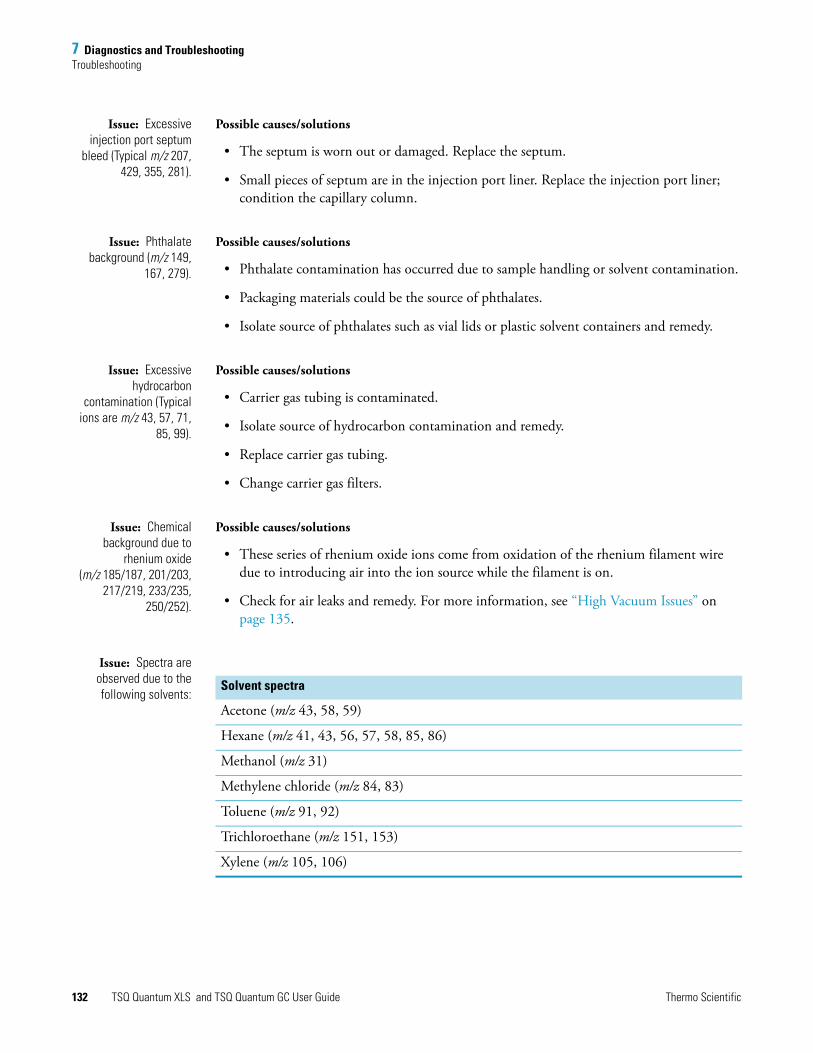
7 Diagnostics and TroubleshootingTroubleshooting
Issue: Excessiveinjection port septum
bleed (Typical m/z 207,429, 355, 281).
Possible causes/solutions
• The septum is worn out or damaged. Replace the septum.
• Small pieces of septum are in the injection port liner. Replace the injection port liner; condition the capillary column.
Issue: Phthalatebackground (m/z 149,
167, 279).
Possible causes/solutions
• Phthalate contamination has occurred due to sample handling or solvent contamination.
• Packaging materials could be the source of phthalates.
• Isolate source of phthalates such as vial lids or plastic solvent containers and remedy.
Issue: Excessivehydrocarbon
contamination (Typicalions are m/z 43, 57, 71,
85, 99).
Possible causes/solutions
• Carrier gas tubing is contaminated.
• Isolate source of hydrocarbon contamination and remedy.
• Replace carrier gas tubing.
• Change carrier gas filters.
Issue: Chemicalbackground due to
rhenium oxide(m/z 185/187, 201/203,
217/219, 233/235,250/252).
Possible causes/solutions
• These series of rhenium oxide ions come from oxidation of the rhenium filament wire due to introducing air into the ion source while the filament is on.
• Check for air leaks and remedy. For more information, see “High Vacuum Issues” on page 135.
Issue: Spectra areobserved due to thefollowing solvents:
Solvent spectra
Acetone (m/z 43, 58, 59)
Hexane (m/z 41, 43, 56, 57, 58, 85, 86)
Methanol (m/z 31)
Methylene chloride (m/z 84, 83)
Toluene (m/z 91, 92)
Trichloroethane (m/z 151, 153)
Xylene (m/z 105, 106)
132 TSQ Quantum XLS and TSQ Quantum GC User Guide Thermo Scientific
7 Diagnostics and TroubleshootingTroubleshooting
Possible causes/solutions
• There is residual solvent from a cleaning procedure or laboratory background contamination. When you finish performing a cleaning procedure, allow cleaned components to dry thoroughly. Warm parts in the GC oven to drive off residual solvent.
• The observed compounds have been introduced through sample injection. The ultimate source is either a sample solvent or the autosampler rinsing solvent. Optimize GC method to separate solvent peak from the area of interest in the chromatogram.
Filament and Lens Control Issues
The lifetime of a filament depends on its exposure to oxygen and solvent vapors. The filament assembly protects the filament and increases its lifetime for many months.
Xcalibur diagnostics test the filament for continuity and current regulation. Testing the filament for continuity before each acquisition ensures that an open filament condition will stop an autosampler sequence and generate an error message.
Diagnostics test the lenses of the TSQ Quantum XLS and TSQ Quantum GC mass spectrometers. A flat line, which represents voltage readback versus the predicted voltage ramp, indicates a lens or other control fault. Contamination causes lens performance to deteriorate over time; the amount of time depends on what type of sample and ionization mode you use.
Issue: Diagnosticsindicate that thefilament is open.
Possible cause/solution
• The filament is open. Vent the system and remove the filament. Normal resistance is 1.0 Ω. Replace if open.
Issue: Unstableemission current.
Possible cause/solution
• The filament is near the end of its life span. Replace the filament.
Issue: Short filamentlifetime.
Possible causes/solutions
• There is an air leak contributing to short filament lifetime. Check for leaks; repair if any are found. For more information, see “High Vacuum Issues” on page 135.
• The filament is on during the solvent peak. Increase acquisition delay time until the solvent peak has passed.
• High emission current is being used. Use lower emission current to extend lifetime.
CAUTION Handle the lenses with care, and do not use harsh cleaning techniques. Damaged lenses cause short circuits, which in turn can cause damage to the lens drivers.
Thermo Scientific TSQ Quantum XLS and TSQ Quantum GC User Guide 133

7 Diagnostics and TroubleshootingTroubleshooting
Issue: Diagnosticsindicate a flat lens
response.
Possible causes/solutions
• The power supply to the lens has a fault. Contact Thermo Fisher Scientific Technical Support.
• There is a fault with the lens drivers. Contact Thermo Fisher Scientific Technical Support.
Heated Zone Issues
The ion source and transfer line are heated zones. The mass spectrometer controls the ion source heater and the Aux1 heated zone of the TRACE GC Ultra controls the transfer line heater.
A heated zone problem is often the result of downloading an instrument method to the instrument that has a different setpoint than the current setting, causing a delay while the heated zone heats or cools.
Component failures are less common but can occur. These are usually related to open circuits in heater cartridges or faulty temperature sensors.
This manual does not discuss heated zones in the gas chromatograph.
Issue: Excessivechromatographic peak
tailing.
Possible causes/solutions
• The ion source, transfer line, or both are not hot enough. Increase the transfer line temperature so that it is at least as hot as the highest GC oven temperature. Then, try increasing the ion source temperature.
• The sample analyte is adsorbing in the GC injector. Clean and deactivate the injection liner. You can also try liners made of different materials.
• The GC oven is not ramped to a high enough temperature. Extend upper oven temperature.
• The GC column must be replaced or does not have the appropriate stationary phase for your application. Change the GC column. See “Removing and Installing a GC Capillary Column” on page 121.
• The GC column does not extend far enough past the end of the transfer line tip. If the end of the column is inside the tip, an excessive amount of GC effluent will contact the inside wall of the tip. Follow the procedure described in “Installing a GC Capillary Column” on page 123.
134 TSQ Quantum XLS and TSQ Quantum GC User Guide Thermo Scientific

7 Diagnostics and TroubleshootingTroubleshooting
Issue: Source heaterwill not heat.
Possible causes/solutions
• No contact between the ion source temperature sensor and the heater block. For accurate temperature readings of the heater block, fully screw the threaded standoff into the ion source to ensure contact between the temperature sensor and the heater block. See “Reassembling the L1, L2, L3 Lens Assembly” on page 95.
• One or more heater cartridges on the EI/CI Source PCB is defective. Replace the EI/CI Source PCB. See “Complete Disassembly and Reassembly of the Ion Source” on page 108.
• The ion source temperature sensor (RTD) is defective. Replace the EI/CI Source PCB. See “Complete Disassembly and Reassembly of the Ion Source” on page 108.
Issue: Source heateroverheats.
Possible cause/solution
• The ion source temperature sensor (RTD) is defective. Replace the EI/CI Source PCB if necessary. See “Complete Disassembly and Reassembly of the Ion Source” on page 108.
Issue: Transfer line willnot heat.
Possible causes/solutions
• Aux1 zone of the GC is not configured for MS Transfer Line. Configure Aux1 zone of the GC and set transfer line temperature in the GC Method Editor.
• Transfer line heater elements are defective. Replace the transfer line.
• The transfer line temperature sensor (RTD) is defective. Replace the transfer line.
Issue: Transfer lineoverheats.
Possible cause/solution
• The transfer line temperature sensor is defective. Replace the transfer line.
High Vacuum Issues
High vacuum problems can become obvious in two ways:
• An intermittent vacuum condition (the vacuum pressure in the vacuum manifold fluctuates intermittently) can cause chromatographic signals to drop out; or if the pressures exceed the maximum allowed pressures set in the Xcalibur data system (see Table 3 on page 55), then the TSQ Quantum XLS or TSQ Quantum GC turns off.
• If the vacuum is consistent enough that it does not exceed the maximum allowed pressure and avoids automatic shutdown of the Xcalibur system, non-reproducible false chromatographic peaks can be generated in the chromatogram.
Typical forepressure readbacks are 30 to 40 mTorr (in EI mode), and typical manifold pressure (ion gauge readback) is 2 × 10⁻⁵ Torr with argon collision gas on, and 2 × 10⁻⁶ Torr with Ar collision gas off.
Thermo Scientific TSQ Quantum XLS and TSQ Quantum GC User Guide 135

7 Diagnostics and TroubleshootingTroubleshooting
The most reliable way to find vacuum leaks is to spray a gas around the vacuum manifold and look for the characteristic ions in full-scan EI mode. Argon produces m/z 40. Or, you can use compressed electronic dusting spray containing an HFC. For example, Falcon Dust-Off™ and MicroCare Micro-Blast™ contain tetrafluoroethane, which produces ions at m/z 69 and 83.
Issue: Forepump willnot turn on.
Possible causes/solutions
• The forepump is off. Check the forepump switch.
• The vacuum service switch is in the Off position. Place the vacuum service switch in the operating position.
• The forepump power cable from the mass spectrometer is not connected. Connect the power cable.
• The forepump is faulty. Replace the forepump.
Issue: Forepumppowers on, but will not
pump down.
Possible causes/solutions
• The oil level in the forepump is insufficient. Check oil level; add oil if necessary.
• The foreline is leaking. Check the clamps and connectors. Replace the foreline hose if a hole is found.
• The vacuum manifold cover is leaking.
• The forepump is faulty. Replace the forepump.
Issue: Turbo pumpshuts off during
operation.
Possible cause/solution
• The foreline pressure is too high. Check for leaks in the foreline.
Issue: Unexpected fullventilation occurs.
Possible causes/solutions
• A gross leak is present. Check for leaks.
• The system was vented through the inlet valve. Close and plug the inlet valve.
• The GC column broke at the transfer line. Replace the GC column. See “Removing and Installing a GC Capillary Column” on page 121.
• The foreline was cut. Replace the foreline hose.
Note The mass spectrometer performs a leak check during the automatic tuning and calibration procedure and during the maintenance tune procedure.
136 TSQ Quantum XLS and TSQ Quantum GC User Guide Thermo Scientific

7 Diagnostics and TroubleshootingTroubleshooting
Issue: Vacuum is faulty. Possible Solutions
• A gross leak is present. Check for leaks.
• The pressure in the analyzer region of the vacuum manifold, as measured by the ion gauge, must be below the pressures listed in Table 3 on page 55.
Linearity Issues
Linearity issues occur when a plot of intensity versus concentration of a known compound is not linear. Poor instrument operating conditions can cause linearity problems. In addition, certain compounds do not give a desired linear response due to chromatographic activity.
A well-maintained instrument provides good linear response over a wide range of concentrations for most compounds. Like all instruments, however, the TSQ Quantum XLS and TSQ Quantum GC mass spectrometers have a saturation point.
Perform routine injector and column maintenance to minimize linearity problems. Usually, a hardware fault that affects linearity shows different issues than those that might be attributed to linearity.
Issue: Calibration plotsnot sufficiently linear.
Possible causes/solutions
• High-end standards are too concentrated for the MS. Use the split injection technique to decrease the amount of sample, or lower emission current to reduce MS sensitivity.
• The ion volume and lenses are dirty. Clean ion volume and lenses as described in “Cleaning Ion Source Components” on page 87.
• The electron multiplier setting is incorrect. Run the tune and calibration procedure as described in “Running Auto Tune and Calibration” on page 64.
• The injection port liner or capillary column is dirty. Change the injection port liner and trim the capillary column.
• The capillary column stationary phase is too thin for high concentration samples. Use a higher capacity capillary column with a thicker stationary phase, or use a split injection technique.
• The capillary column is bad. Replace the capillary column. See “Removing and Installing a GC Capillary Column” on page 121.
Thermo Scientific TSQ Quantum XLS and TSQ Quantum GC User Guide 137
7 Diagnostics and TroubleshootingTroubleshooting
Power Supply Issues
Xcalibur diagnostics detect most power supply issues. Power supply problems often involve a blown fuse, faulty electronic components, or something as simple as a disconnected cable. Have a Thermo Fisher Scientific field service engineer replace a blown fuse.
Issue: TSQ QuantumXLS will not power on.
Possible causes/solutions
• The power cord is disconnected. Verify that the power cord is plugged in.
• Voltage is not coming from the electrical outlet. Verify that the electrical outlet is operational.
• The Power Module is faulty. Contact Thermo Fisher Scientific Technical Support.
Issue: The TSQQuantum XLS powers on
but trips the circuitbreaker.
Possible causes/solutions
• The Power Module is faulty. Contact Thermo Fisher Scientific Technical Support.
• The forepump causes the circuit breaker to trip. Check forepump; replace it if necessary.
Sensitivity Issues
If you observe a drop in instrument sensitivity, determine if the sensitivity drop was sudden or if it occurred gradually. A sudden loss of sensitivity can be the result of sudden component failure or an unnoticed change in the analytical method. Simple errors such as a plugged autosampler syringe or too low sample level in the sample vial can give the appearance of instrument failure.
Gradual drops in sensitivity are usually the result of ion volume or lens contamination, and are easily remedied by cleaning the ion volume or lenses.
The electron multiplier influences sensitivity and has a limited lifetime. Eventually you must replace the electron multiplier.
Improper GC maintenance is another cause of diminished sensitivity. It is important to establish a routine maintenance program for the GC. For more information on establishing a maintenance program, refer to the TRACE GC Maintenance Manual.
138 TSQ Quantum XLS and TSQ Quantum GC User Guide Thermo Scientific
7 Diagnostics and TroubleshootingTroubleshooting
Issue: Thechromatogram has a low
total ion current signal.
Possible causes/solutions
• The GC temperature ramp does not continue to a high enough temperature to elute high boiling point compounds. Multiple injections cause these compounds to accumulate in a column, reducing sensitivity. Extend upper temperature or the time at upper temperature in the GC oven ramp.
• The instrument is out of tune, or the tune file is incorrect. Select the correct tune file for the method or run automatic tune as described in “Running Auto Tune and Calibration” on page 64.
• The ion volume is contaminated. Clean the ion volume.
• The ion volume is incorrectly positioned. Position the ion volume properly.
• The magnets above and below the ion source are installed incorrectly. Position both magnets so that the south pole is on top. Electrons will not focus into the ion volume if one magnet is upside down.
• Dust has collected in the electron multiplier or on the conversion dynode. Contact Thermo Fisher Scientific Technical Support.
• The emission current is set too low. Check the setting listed for the emission current.
• The ground connection between the Electrometer PCB and anode feedthrough is faulty. Contact Thermo Fisher Scientific Technical Support.
• There is a problem with the filament or lens control. See “Filament and Lens Control Issues” on page 133 for more information.
• The EI/CI Source PCB is faulty, which allows emission current to leak to ground. Contact Thermo Fisher Scientific Technical Support.
• Reagent gas is leaking into the analyzer and suppressing EI signal. Check for presence of CI reagent ions in the spectrum. Replace CI Gas Flow Module if necessary.
Thermo Scientific TSQ Quantum XLS and TSQ Quantum GC User Guide 139

7 Diagnostics and TroubleshootingTroubleshooting
Issue: Poor compoundsensitivity.
Possible causes/solutions
• The syringe, injection port liner, and column depth in the injector are incorrectly matched. For the correct combination, refer to the TRACE GC Ultra Operators Manual.
• Sample delivery is insufficient due to a plugged syringe needle. Clean or replace the syringe.
• The injection port liner is contaminated. Clean or replace the injection port liner.
• Graphite or septa particles contaminate the injection port. Clean the injection port.
• The injector or septum is leaking. Replace septum and perform leak check on the GC.
• The capillary column is at the end of its life span. Replace the capillary column.
• Method development problems are present. Contact Thermo Fisher Scientific Technical Support.
Issue: Sensitivity isunstable or shows
decrease with repeatedinjections.
Possible causes/solutions
• The GC temperature ramp does not continue to a high enough temperature to elute high boiling point compounds. Multiple injections cause these compounds to accumulate in a column, reducing sensitivity. Extend the upper temperature or the time at upper temperature in the GC oven ramp.
• The ion volume or lenses are contaminated. Clean the ion volume and lenses as described in “Cleaning Ion Source Components” on page 87.
• The ion source temperature is too low and causes the ion source to contaminate too quickly. Clean ion volume and lenses as described in “Cleaning Ion Source Components” on page 87 and then raise ion source temperature.
• There is a problem with the filament emission current control. See “Filament and Lens Control Issues” on page 133 for more information.
• The electron multiplier is faulty. Contact Thermo Fisher Scientific Technical Support.
• The injection port liner or capillary column is contaminated. Replace the injection port liner and trim the capillary column.
140 TSQ Quantum XLS and TSQ Quantum GC User Guide Thermo Scientific

7 Diagnostics and TroubleshootingTroubleshooting
Issue: Poor sensitivityin CI mode.
Possible causes/solutions
• An EI ion volume is installed. Install a CI ion volume as described in “Changing Ionization Modes” on page 75.
• The small hole in the CI ion volume is plugged. Use a dental pick or old syringe needle to clear it.
• The filament is not aligned. Remove the ion volume and check if the ion burn is centered around the small electron entrance hole. Be sure the filament is properly inserted into the connector. Carefully bend the filament wire to better align it with the ion volume.
• The ion volume is not inserted properly. While running the instrument, you can push on the ion volume with the I/R tool. Be sure to monitor the pressure to ensure that you get a good seal around the I/R tool. Otherwise, you might damage the filament. An increase in signal calibration gas as you push on the ion volume usually indicates that the filament is not aligned properly.
Stability Issues
Stability helps provide consistent instrument precision and the reproducibility of accurate results. Good operating conditions for the mass spectrometer, gas chromatograph, and autosampler contribute to instrument stability.
Sample preparation, spiking errors, sample injection errors, and lack of routine maintenance on the instruments can cause false stability issues.
When hardware faults affect instrument stability, investigate simple solutions first, such as cleaning the ion volume and lenses, or checking for air leaks. Usually, a hardware fault that affects stability shows different issues than those which might be attributed to stability.
Issue: The signalresponse is unstable ordrops out unexpectedly.
Possible causes/solutions
• There is a problem with the filament or lens control. See “Filament and Lens Control Issues” on page 133 for more information.
• There is an air leak. Run the maintenance tune or the Xcalibur auto tune and calibration procedure, which performs a leak check and returns a pass or fail message. If necessary, check for leaks. See “High Vacuum Issues” on page 135 for more information.
• There is a high vacuum problem. See “High Vacuum Issues” on page 135 for more information.
• There is a contamination problem. See “Contamination Issues” on page 131 for more information.
• Dust has collected in the electron multiplier or on the conversion dynode. Contact Thermo Fisher Scientific Technical Support.
Thermo Scientific TSQ Quantum XLS and TSQ Quantum GC User Guide 141

7 Diagnostics and TroubleshootingTroubleshooting
Tuning Issues
You can suspect a tuning problem when Xcalibur auto tune and calibration fails. The auto tune and calibration procedure performs several functions, and issues or error messages indicate different problems. Diagnostics can usually uncover a tuning problem.
Issue: “Cannot findCalibration Gas” error
message received.
Possible causes/solutions
• There is a mechanical problem with the ion source or lenses. Verify that an EI ion volume is installed. Verify correct orientation and cleanliness of ion volume. Verify cleanliness and correct operation of lenses.
• Tune file settings are out of usable range. Restore default tune settings and calibration settings. Run Auto Tune and Calibration. See “Tuning and Calibrating” on page 61.
• The calibration gas vial is empty. Add 100 μL (max) of calibration compound to calibration gas vial. See “Adding Calibration Compound” on page 117.
Issue: The electronmultiplier gain
calibration fails.
Possible causes/solutions
• The electron multiplier has not been given sufficient time to outgas since venting. Allow more time to pump out.
• The GC column flow is too high. Lower it to1 mL/min.
• The multiplier is near the end of its lifetime. Multipliers typically last about 2 to 3 years before they are too noisy for the gain to be set accurately. Contact Thermo Fisher Scientific Technical Support.
• The multiplier power supply is faulty. Contact Thermo Fisher Scientific Technical Support.
• The filament is the source of too much background noise. See “Filament and Lens Control Issues” on page 133 for more information.
• Chemical background in the manifold is elevated. Remedy leaks or sources of water contamination in carrier gas. See “High Vacuum Issues” on page 135 for more information.
• The difference between the electron energy and the setpoint is greater than 5 V. Contact Thermo Fisher Scientific Technical Support for assistance.
142 TSQ Quantum XLS and TSQ Quantum GC User Guide Thermo Scientific

7 Diagnostics and TroubleshootingTroubleshooting
Issue: Poor high massresponse.
Possible causes/solutions
• Poor high m/z ion intensity because the ion source temperature is too high. Reduce the ion source temperature to reduce the amount of thermal decomposition and fragmentation of your analyte.
• Poor high m/z ion intensity because of bad ion source lens settings. Run the tune and calibration procedure. See “Tuning and Calibrating” on page 61.
• Helium pressure in the ion source is too high or low. Set flow to 1.0 mL/min for most applications.
• There is a vacuum leak. Find and repair any leaks. Be sure to check the transfer line fitting in the GC oven. See “High Vacuum Issues” on page 135 for more information.
• An excess amount of low m/z ions, such as hydrocarbons or column bleed. Remedy the source of these low m/z ions.
• The ion volume or lenses are contaminated. Clean the ion volume or lenses. See “Cleaning Ion Source Components” on page 87.
• m/z 131 is not base peak because the multiplier gain is too low. The multiplier gain calibration may set the multiplier voltage too low for a noisy multiplier. Electron multipliers older than 2 to 3 years are often noisy. Contact Thermo Fisher Scientific Technical Support.
• There is poor high m/z intensity and poor resolution of low m/z ions because the conversion dynode is faulty. Contact Thermo Fisher Scientific Technical Support.
• The injection rf is not calibrated. Run the tune and calibration procedure as described in “Tuning and Calibrating” on page 61.
• There is a problem with the filament or lens control. See “Filament and Lens Control Issues” on page 133 for more information.
• Reagent gas is leaking into the analyzer and suppressing the EI signal. Check for the presence of CI reagent ions in the spectrum. Replace the CI Reagent Gas Flow Module if necessary.
Thermo Scientific TSQ Quantum XLS and TSQ Quantum GC User Guide 143
7 Diagnostics and TroubleshootingReplacing a Fuse
Issue: Weak signal. Possible causes/solutions
• The ion volume or ion source lenses are dirty. Clean the contaminated components as described in “Cleaning Ion Source Components” on page 87.
• The multiplier is set too low. Run multiplier gain calibration in the tune and calibration procedure as described in “Tuning and Calibrating” on page 61. An electron multiplier older than 2–3 years may be too noisy for the multiplier gain calibration to accurately set the voltage. You might need to replace the electron multiplier. Contact Thermo Fisher Scientific Technical Support.
• The wrong type of ion volume is installed. EI and CI require different ion volumes. They may not be used interchangeably. Change the ion volume as described in “Changing Ionization Modes” on page 75.
• The ion volume is absent or incorrectly positioned. Verify that the ion volume is positioned correctly.
• There is a filament or lens control problem. See “Filament and Lens Control Issues” on page 133 for more information.
• The electron multiplier is faulty. Contact Thermo Fisher Scientific Technical Support.
Replacing a Fuse
Replacing PCBs and Power Supplies
CAUTION Fuses protect the various circuits by opening the circuits whenever overcurrent occurs. On the TSQ Quantum XLS and TSQ Quantum GC mass spectrometers, a failed fuse indicates a failed board or electronic module that must be replaced by a Thermo Fisher Scientific field service engineer.
CAUTION The TSQ Quantum XLS and TSQ Quantum GC mass spectrometer electronic assemblies are close packed to minimize the size of the system. Due to the complexity of removing and reinstalling the mass spectrometer electronic assemblies, only a Thermo Fisher Scientific field service engineer can replace electronic assemblies.
144 TSQ Quantum XLS and TSQ Quantum GC User Guide Thermo Scientific

8
Using the Direct Sample Probe
With the direct sample probes (direct insertion probe and direct exposure probe) you can introduce compounds directly into the ion source without GC column separation. This chapter covers, step-by-step, a direct insertion probe (DIP) experiment using perfluorotetracosane (CF3(CF2)22CF3, molecular weight 1238.18, melting point 190 ºC). You can perform a similar experiment using your compound.P
Creating an Instrument MethodAn instrument method contains the settings that the TSQ Quantum XLS or TSQ Quantum GC mass spectrometer uses during an experiment. Use the Instrument Setup view to create the instrument method.
To create an instrument method
1. On the Xcalibur Home Page, click the Instrument Setup icon to open the Instrument Setup view.
2. Click the TSQ icon in the viewbar.
3. Choose TSQ > Regular Method to open the regular method Scan Editor page.
4. On the Scan Editor page, create a one segment, one scan event instrument method. In this example, the segment is 8 minutes long (see Figure 69).
Contents
• Creating an Instrument Method
• Creating a Sequence
• Preparing the Probe and Inlet Valve
• Preparing the Mass Spectrometer
• Running the Sequence
• Examining the Raw Data in Qual Browser
• Removing the Probe
Thermo Scientific TSQ Quantum XLS and TSQ Quantum GC User Guide 145
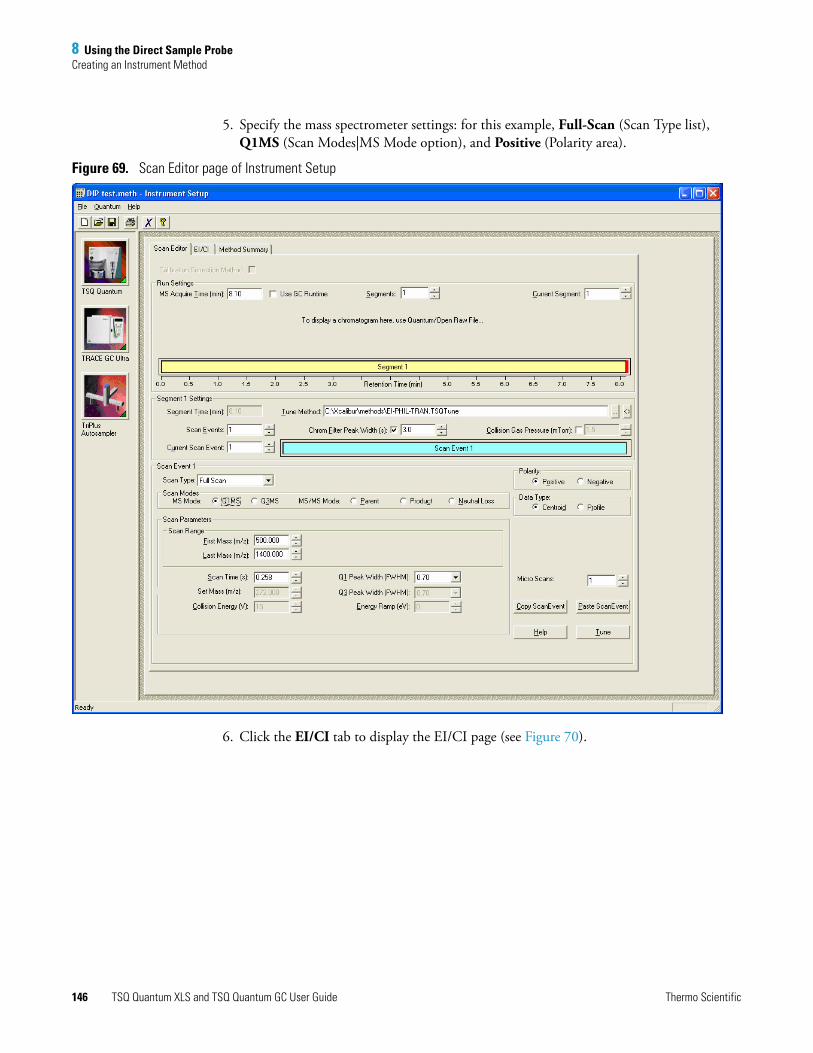
8 Using the Direct Sample ProbeCreating an Instrument Method
5. Specify the mass spectrometer settings: for this example, Full-Scan (Scan Type list), Q1MS (Scan Modes|MS Mode option), and Positive (Polarity area).
Figure 69. Scan Editor page of Instrument Setup
6. Click the EI/CI tab to display the EI/CI page (see Figure 70).
146 TSQ Quantum XLS and TSQ Quantum GC User Guide Thermo Scientific

8 Using the Direct Sample ProbeCreating an Instrument Method
Figure 70. EI/CI page of Instrument Setup
7. Enter or select the following settings:
• Number of States: 1
• State at Start of Run: On
• Calibration Gas Setting: Off
• Use DIP/DEP Probe:
This example is an EI experiment with a 200 μA emission current.
8. Save the instrument method.
a. Choose File > Save As to open the Save As dialog box.
b. Save the instrument method as a .meth file. In this example we name the instrument method Dip test.meth.
Thermo Scientific TSQ Quantum XLS and TSQ Quantum GC User Guide 147

8 Using the Direct Sample ProbeCreating a Sequence
Creating a SequenceA sequence contains sample information—one sample per row. In this example the sequence has one sample.
To create a sequence
1. Click Start > Programs > Thermo Xcalibur > Xcalibur to open the Xcalibur Home Page.
2. On the Xcalibur Home Page, click the Sequence Setup icon to open the Sequence Setup view (see Figure 71).
3. Enter the name and path of the instrument method. In this example, it is C:\Xcalibur\methods\DIP test.
4. Enter a file name and path for the raw file that contains the acquired data. In this example, it is C:\Xcalibur\Data\data01.
Figure 71. Sequence Setup view, showing one sample in the sequence
Note If the sequence has more than one sample, the Xcalibur data system prompts you to reload the probe after each sample.
148 TSQ Quantum XLS and TSQ Quantum GC User Guide Thermo Scientific

8 Using the Direct Sample ProbePreparing the Probe and Inlet Valve
Preparing the Probe and Inlet ValveTo prepare the probe and inlet valve
1. Connect the direct sample probe controller to the mass spectrometer by contact closure with the probe start cable (P/N 70111-63627, in the Accessory Kit).
2. Create a probe method on the controller. Refer to the probe manual. This example uses the following DIP settings:
• Initial temperature: 50 ºC
• Initial time: 5 s
• Ramp rate: 100 ºC/min
• Final temperature: 200 ºC
• Ramp hold time: 200 s
3. Load sample on the probe.
4. Install the guide bar:
a. With the guide ball track facing left, insert the guide bar into the entry housing. See Figure 17 on page 29.
b. Push the guide bar in as far as it goes. Rotate it 90° clockwise to lock the guide bar in the entry housing.
5. Prepare the inlet valve:
a. Make sure the inlet valve is closed with the inlet valve lever down, as shown in Figure 17 on page 29.
b. Loosen the inlet valve knob counterclockwise, and remove the inlet valve plug.
Preparing the Mass SpectrometerTo prepare the mass spectrometer for the experiment
1. If the EZ Tune window is not already open, choose Start > Programs > Thermo Instruments > TSQ > TSQ Tune.
2. Ensure that the TSQ Quantum XLS or TSQ Quantum GC mass spectrometer is the only instrument in use and that there are no start instruments.
a. On the Xcalibur Home Page, click the Sequence Setup icon to open Sequence Setup, if it is not already open.
IMPORTANT You must have the TSQ EZ Tune window open for the mass spectrometer to initiate the probe insertion sequence.
Thermo Scientific TSQ Quantum XLS and TSQ Quantum GC User Guide 149

8 Using the Direct Sample ProbePreparing the Mass Spectrometer
b. In Sequence Setup, choose Actions > Run Sequence. The Run Sequence dialog box opens (see Figure 72).
Figure 72. Run Sequence dialog box, showing instruments in use
c. Click Change Instruments to open the Change Instruments In Use dialog box (see Figure 73).
Figure 73. Change Instruments In Use dialog box, showing the TSQ Quantum mass spectrometer in use and no start instruments
150 TSQ Quantum XLS and TSQ Quantum GC User Guide Thermo Scientific

8 Using the Direct Sample ProbeRunning the Sequence
d. Click any Yes in the In Use column to clear all instruments other than the TSQ Quantum.
e. Ensure that the TSQ Quantum has a Yes in the In Use column. Click the area if necessary.
f. Click any Yes in the Start Instrument column to clear all start instruments.
g. Click OK to save your settings and close the Change Instruments In Use dialog box.
Running the SequenceYou acquire data by running the sequence. The Xcalibur data system saves the acquired data in a raw file.
To run the sequence
1. In the Run Sequence dialog box (see Figure 72 on page 150), click OK to start the acquisition. The Xcalibur system displays a message to insert the probe (Figure 74).
Figure 74. Insert probe message
2. Inset the probe into the inlet valve:
a. Insert the guide ball on the DIP probe into the guide ball hole on the guide bar.
b. Slide the probe forward into the inlet valve until the guide ball is at the guide bar’s first stop. See Figure 75.
c. Tighten the inlet valve knob clockwise to ensure a leak-tight seal.
Note You must have the TSQ EZ Tune or QuickQuan application running so that the Xcalibur application can display instrument methods.
Thermo Scientific TSQ Quantum XLS and TSQ Quantum GC User Guide 151

8 Using the Direct Sample ProbeRunning the Sequence
Figure 75. Probe at the first stop on guide bar
3. Click OK. The forepump evacuates the inlet valve.
4. When the Safe to Open the Valve message appears (Figure 76), click OK.
Figure 76. Safe to open the valve message
5. Pull the inlet valve lever up to open the inlet valve.
6. Slide the probe into the vacuum manifold until the tip of the probe is fully inserted into the ion volume holder. See Figure 77.
Inlet valve knob
First stop on guide bar
Probe
152 TSQ Quantum XLS and TSQ Quantum GC User Guide Thermo Scientific

8 Using the Direct Sample ProbeRunning the Sequence
Figure 77. Probe inserted into the inlet valve
7. When you receive the Acquisition Ready message (Figure 78), click OK. The mass spectrometer is now waiting for contact closure.
Figure 78. Acquisition Ready message.
8. In Sequence Setup, choose View > Real Time Plot View to display the mass spectrum and chromatogram.
9. Start the probe method from the probe controller to initiate data acquisition. See Figure 79 and Figure 80.
Inlet valve
Probe
Thermo Scientific TSQ Quantum XLS and TSQ Quantum GC User Guide 153

8 Using the Direct Sample ProbeRunning the Sequence
Figure 79. Perfluorotetracosane mass spectrum at 0.56 minute retention time
154 TSQ Quantum XLS and TSQ Quantum GC User Guide Thermo Scientific

8 Using the Direct Sample ProbeExamining the Raw Data in Qual Browser
Figure 80. Perfluorotetracosane chromatogram
Examining the Raw Data in Qual BrowserYou can use Qual Browser to display the mass spectrum at various times in the chromatogram.
To examine the raw data
1. On the Xcalibur Home Page, click the Qual Browser icon to open the Qual Browser window.
2. Click on the chromatogram to display the mass spectrum at that retention time. See Figure 81.
Thermo Scientific TSQ Quantum XLS and TSQ Quantum GC User Guide 155

8 Using the Direct Sample ProbeRemoving the Probe
Figure 81. Raw file displayed in Qual Browser
Removing the ProbeTo remove the probe
1. Withdraw the probe until the guide ball on the probe reaches the first stop on the guide bar (Figure 75).
2. Close the inlet valve by pushing the lever down.
3. Loosen the inlet valve knob by turning it counterclockwise.
CAUTION Do not withdraw the probe beyond the point where the guide ball reaches the first stop in the guide bar. Close the inlet valve first. Otherwise, the system vents to the atmosphere.
156 TSQ Quantum XLS and TSQ Quantum GC User Guide Thermo Scientific
8 Using the Direct Sample ProbeRemoving the Probe
4. Continue withdrawing the probe completely from the inlet valve by sliding it through the guide ball track in the guide bar.
5. Store the probe in its case.
6. Remove the guide bar by rotating it 90° counterclockwise and sliding it out of the entry housing.
7. Replace the inlet valve plug and tighten the inlet valve knob clockwise to form a seal. The inlet valve plug prevents air from entering the vacuum manifold in case the inlet valve is accidentally opened. You can also remove the inlet valve lever by pulling it free.
Thermo Scientific TSQ Quantum XLS and TSQ Quantum GC User Guide 157

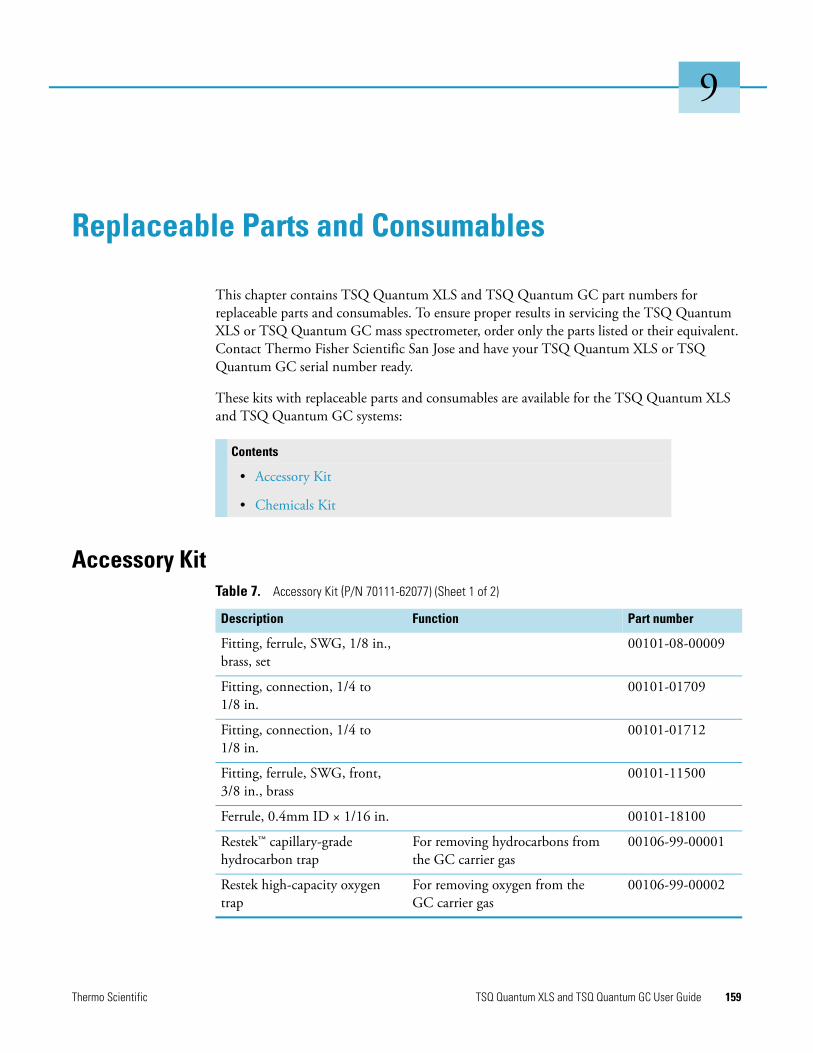
9
Replaceable Parts and Consumables
This chapter contains TSQ Quantum XLS and TSQ Quantum GC part numbers for replaceable parts and consumables. To ensure proper results in servicing the TSQ Quantum XLS or TSQ Quantum GC mass spectrometer, order only the parts listed or their equivalent. Contact Thermo Fisher Scientific San Jose and have your TSQ Quantum XLS or TSQ Quantum GC serial number ready.
These kits with replaceable parts and consumables are available for the TSQ Quantum XLS and TSQ Quantum GC systems:
Accessory Kit
Contents
• Accessory Kit
• Chemicals Kit
Table 7. Accessory Kit (P/N 70111-62077) (Sheet 1 of 2)
Description Function Part number
Fitting, ferrule, SWG, 1/8 in., brass, set
00101-08-00009
Fitting, connection, 1/4 to 1/8 in.
00101-01709
Fitting, connection, 1/4 to 1/8 in.
00101-01712
Fitting, ferrule, SWG, front, 3/8 in., brass
00101-11500
Ferrule, 0.4mm ID × 1/16 in. 00101-18100
Restek™ capillary-grade hydrocarbon trap
For removing hydrocarbons from the GC carrier gas
00106-99-00001
Restek high-capacity oxygen trap
For removing oxygen from the GC carrier gas
00106-99-00002
Thermo Scientific TSQ Quantum XLS and TSQ Quantum GC User Guide 159

9 Replaceable Parts and ConsumablesChemicals Kit
Chemicals Kit
Cotton swabs For applying cleaning paste to stainless steel parts
00301-01-00015
Tubing, 1/8 in., copper, precleaned
Gas lines 00301-22701
Ball valve seal kit (replacement)
For replacing the ball valve seal in the inlet valve
119265-0003
Lens alignment tool For aligning ion source lenses 1, 2, and 3
120271-0001
Filament assembly For replacing a failed filament in the ion source
120320-0030
Nitrile gloves medium For handling clean parts that are under vacuum
23827-0008
Nitrile gloves large For handling clean parts that are under vacuum
23827-0009
Syringe, 10 uL, 80 mm For adding calibration compound 36502019
Tee union, 1/8 in. 00101-01-00012
Cable, start, probe Contact closure cable between the direct sample probe and the mass spectrometer
70111-63627
Cable, start, GC Contact closure cable between the GC and the mass spectrometer
70111-63626
Forceps, 10 in., stainless steel For handling ion volumes and clean components
76360-0400
Cable, 10 base-T, crossover, 15 ft, shielded
76396-0052
Table 7. Accessory Kit (P/N 70111-62077) (Sheet 2 of 2)
Description Function Part number
Table 8. Chemicals Kit (P/N 70111-62078)
Description Function Part number
Perfluorotributylamine (FC-43) Tuning and calibration compound 50010-02500
Aluminum oxide Cleaning stainless steel parts 32000-60340
Benzohexane Performance testing 120150-TEST
Octafluoronaphthalene Performance testing 120150-TEST
160 TSQ Quantum XLS and TSQ Quantum GC User Guide Thermo Scientific

I
Index
AAccessory Kit 159aluminum oxide 160analyzer assembly, lenses, voltages applied to 39analyzer chamber, location (figure) 43Analyzer Control PCB, discussion 47analyzer region, vacuum manifold
description 42location 42
anode, electron multiplier, description 39Auto Tune and Calibration 64automatically 64autosampler
cofiguration 18photo 2power outlet 24startup 53, 56TriPlus 18troubleshooting communication problems 131
Bball valve
extraction tool (figure) 120extraction tool, using 120seal, replacing 120
ball valve seal kit 159benzohexane 160
Ccables 160calibrating
and H-SRM (note) 61discussed 61frequency (note) 61running 64tune and calibration report 67
calibration compoundadding 117flow control, description 45
mass spectrum, displaying 62observed peaks 62on, off 62spectrum, positive EI mode 64
calibration compound viallocation (figure) 117–118removing and reinstalling 117–118
calibration gas valve, description 45capillary column
conditioning 124installing 123removing 121removing ion source (Caution) 91, 97
cathode, electron multiplier, description 39Cautions
emergency shutdown 23, 49forepump and line power 44I/R tool removal, withdrawing 80, 83removing ion source and capillary column 91, 97replacing fuses 144replacing PCBs and power supplies 144
centroid scan, defined 15chemical ionization (CI)
discussed 4gas valve, description 45methane 4removing ion volume 75
Chemicals Kit 160circuit breaker 23–24cleaning
aluminum parts 115ceramic parts 115frequency 86ion volumes 90lenses L1, L2, L3, L4 90, 96list (table) 86stainless steel parts 113
collision cellfigure 34location (figure) 43
collision energy (Q2 offset voltage) 38
Thermo Scientific TSQ Quantum XLS and TSQ Quantum GC User Guide 161

Index: D
collision gas valve, description 45collision gas, description 36collision-induced dissociation (CID), discussion 36column bleed contamination 131Communication LED
description 22figure 22mass spectrometer reset 57mass spectrometer startup 55
complianceregulatory iiiWEEE v
computer, features 48consumables 159contamination
column bleed 131phthalates 132septum bleed 132solvent ions 133troubleshooting 131
Convectron gauge, description 44conversion dynode
description 39figure 40
Ddata dependent scan mode, discussed 12data system
description 47GC interface 48instrument interface 48LAN interface 48personal computer 48primary Ethernet adapter 48shutdown 53
data types, discussed 15detector system 39diagnostics, running 127DIP (direct insertion probe), example procedure
1 creating an instrument method 1452 creating a sequence 1483 preparing the probe and inlet valve 1494 preparing the mass spectrometer 1495 running the sequence 1516 examining the data 155perfluorotetracosane 145
direct insertion probe (DIP), perfluorotetracosane example procedure 145
direct sample probeand inlet valve 149direct exposure probe (DEP) 19direct insertion probe (DIP) 19
inserting into inlet valve (figure) 152mass spectrometer, preparing 149photo 20using 145
dynode 39
Eelectron ionization (EI)
discussed 4removing ion volume 75
electron multiplieranode, description 39description 39figure 40
electronic assembliesdescription 46ion detection system 47Power Entry Module, description 46RF voltage generation, description 47
electronics service switchdescription 24location (figure) 25mass spectrometer components On/Off status 59
embedded computerdescription 46resetting 57
emergency shutdownCaution 23front panel system power off button 23procedure 49system power off button 49
Ethernet 48Ethernet Link OK LED 25
FFC-43
adding 117mass spectrum, displaying 62observed peaks 62part number 160spectrum, positive EI mode 64turning flow on and off 62
ferrules 159filament
description 28location (figure) 26–27, 105, 107part number 104, 106problems, troubleshooting 133replaceable parts 160replacing 104, 106turning on and off 62
162 TSQ Quantum XLS and TSQ Quantum GC User Guide Thermo Scientific

Index: G
filters 46fittings 159forepump
description 44maintainence 116power cord (Caution) 44
forpumppower outlet (figure) 25
front panel LEDsCommunication 22description 22figure 22Power 22Scan 23System 23Vacuum 22
front panel system power off buttonfigure 23
full scan type 12functional description
autosampler 18data system 47direct sample probes 20gas chromatograph (GC) 19inlet valve 29ion optics 30mass analyzer 33mass spectrometer 21Q0 quadrupole 30transfer line 20TSQ Quantum GC 17
fuses, mass spectrometer, replacing 144
Ggas chromatograph (GC)
capillary column, installing 123capillary column, removing 121column installation 123communication with data system 48configuring 19functional description 19leak check 124photo 2power outlet 24retention time correction (iSRM) 14startup 53–54troubleshooting communication problems 130
guide barfigure 29, 76intalling 75
Hhydrocarbon trap 159
Iinlet gases hardware
calibration compound 45CI gas valve 45collision gas valve 45description 41functional block diagram 41
inlet valveand direct sample probe 149Caution 80, 83components (figure) 77description 29figure 29guide bar 29Insert Probe message 77insertion/removal (I/R) tool, inserting 77ion volumes, installing 82lever, removing 84plug orientation 84procedure 76Safe to Insert Probe message 78
Insert Probe message (figure) 77insertion/removal (I/R) tool
figure 29, 76inserting 77ion volumes, removing and installing 81lock position 80unlock position 76withdrawal (Caution) 80, 83
Instrument Configuration window, opening 18–19instrument method, creating 145intelligent selected reaction monitoring (iSRM) 14ion detection system
conversion dynode 39description 39electron multiplier 39electron multiplier gain 40electronic assemblies 47
ion gaugedescription 44location (figure) 43
ion optics, description 30ion polarity modes,discussed 5ion source
cleaning 104, 106cleaning components 87cross-sectional view (figure) 31description 26dissassembling completely 108, 110
Thermo Scientific TSQ Quantum XLS and TSQ Quantum GC User Guide 163
Index: L
electrical connections 53, 91, 97exploded view (figure) 88–89figure 26–27filament, replacing 104, 106filament,replacing 104ion source lenses, reinstalling 95, 103Ion Source PCB, location (figure) 109, 111lens assembly, disassembling 94, 100lens assembly, removing 93, 99lenses, cleaning 90, 96lenses, reassembling 95, 102less assembly, exploded view 94, 101location (figure) 53, 91, 97reinstalling 95, 103removing 91, 97
ion source block, location (figure) 26–27ion source chamber, location (figure) 43Ion Source PCB
location (figure) 26–27, 53, 91, 97, 108, 110reinstalling 110, 112
ion transmission devicedefined 6rod assembly 6
ion volumesattaching and removing from I/R tool 81cleaning 90figure 28installing 82location (figure) 83removing 75
ionization modeschanging 75chemical ionization (CI) 4discussed 4electron ionization (EI) 4
iSRM scan type 14
Lleak check, GC 124leak checking 136LEDs
Communication LED 22Communication LED, mass spectrometer reset 57Communication LED, mass spectrometer startup 55Ethernet Link OK 24–25Forepump On 24Power LED 22Power LED, mass spectrometer reset 57Power LED, mass spectrometer startup 55Pump On, location (figure) 25Scan LED 23System LED 23
System LED, mass spectrometer reset 57System LED, mass spectrometer startup 55Vacuum LED 22Vent Valve Closed 24Vent Valve Closed (figure) 25
lens alignment tool 159lens L1, L2, L3, and L4
location (figure) 27lens L1, L2, L3, and L4, location (figure) 26lenses
analyzer assembly, voltages applied to 39ion source lenses exploded view 94, 101ion source lenses, reassembling 95, 102ion source lenses, reinstalling 95, 103L1, L2, L3 exploded view 94, 101L1, L2, L3, L4 (figure) (TSQ Quantum XLS) 26L1, L2, L3, L4 location (figure) 27L1, L2, L3, L4, cleaning 90, 96L21, L22, L23 (figure) 34L31, L32, L33 (figure) 34
linearity problems, troubleshooting 137
Mmain power circuit breaker
description 23–24location (figure) 24
maintenanceball valve seal, replacing 119forepump 116frequency 86GC column installation 123ion source filament, replacing 106ion source lenses, cleaning 90ion volumes, cleaning 90procedures (table) 85
mass analysiscollision-induced dissociation 36discussion 34
mass analyzerdefined 6description 33quadrupole rod assembly, functional description 33
mass anaysis, RF and dc fields (figure) 34mass range 15mass spectrometer
CI gas valve 45circuit breaker, location (figure) 25collision gas valve 45electronic assemblies 46electronics service switch, location (figure) 25emergency shutdown 49front panel LEDs 22
164 TSQ Quantum XLS and TSQ Quantum GC User Guide Thermo Scientific

Index: N
functional description 21fuses, replacing 144inlet gasses hardware 41inlet valve (figure) 29ion detection system 39ion detection system electronic assemblies 47ion gauge 44ion optics 30ion source 26–27LEDs and system startup 57maintenance procedures (table) 85mass analyzer 33Off condition 59On/Off status of components 59Power Entry Module, description 46power outlet 24Q0 quadrupole 30resetting 57RF voltage generation electronic assemblies 47right-side power panel 52shutdown 51Standby condition 51, 59startup 53turbomolecular pump 43vacuum manifold 42vacuum service switch, location (figure) 25vacuum system 41vent valve 45
mass spectrometer circuit breaker, location (figure) 25mass spectrometer, and direct sample probe 149mechanical pump 44MS main power circuit breaker, mass spectrometer components On/Off status 59
MS/MS scan modesParent 9Product 7
MS/MS scan modes, Neutral Loss 10
NNeutral Loss scan mode
discussed 10example (figure) 11illustration (figure) 11
Ooctafluoronaphthalene 160Off condition, mass spectrometer components On/Off status 59
offset voltage, quadrupole 37oxygen trap 159
PParent scan mode
discussed 9illustration (figure) 9
Perfluorotetracosane 155personal computer, features 48phthalate contamination 132power cord, forepump (Caution) 44Power Entry Module, description 46Power LED
description 22figure 22mass spectrometer reset 57mass spectrometer startup 55
power supply problems, troubleshooting 138pressure, maximim allowed (table) 55probe button 77procedures
adding calibration compound 117changing ionization modes 75cleaning ion source components 87cleaning ion source lenses 90, 96cleaning ion volumes 90cleaning stainless steel parts 113complete system shutdown 51conditioning capillary columns 124creating QC tune report 71disassembling ion source lens assembly 94, 100displaying FC-43 spectrum 62dissassembling ion source completely 108, 110emergency shutdown 49GC leak checking 124installing capillary column 123installing the ion volume 82maintaining forepump 116operating the inlet valve 75placing system in standby 51reassembly ion source lenses 95, 102reinstalling ion source 95, 103reinstalling ion source lenses 95, 103reinstalling Ion Source PCB 110, 112removing capillary column 121removing ion source 91, 97removing ion source lens assembly 93, 99removing the ion volume 75replacing filament 104, 106replacing ion source filament 104, 106resetting mass spectrometer 57saving tune and calibration report 69starting mass spectrometer 54system startup 53tuning and calibrating 64
Thermo Scientific TSQ Quantum XLS and TSQ Quantum GC User Guide 165

Index: Q
Product scan modediscussed 7illustration (figure) 8
profile scan, defined 15pumps
forepump 44turbomolecular pump 43
QQ0 quadrupole
cross-sectional view (figure) 31description 30figure 30location (figure) 43
Q1 quadrupolefigure 33scan modes 6
Q1MS and Q3MS scan modes 7Q2 rod assembly
figure 34scan modes 6
Q3 quadrupolefigure 33scan modes 6
QC tune reportcreating 72example (figure) 72
QED MS scan type 14quadrupole mass analyzer
functional description 33quadrupole offset voltage 37
quadrupolesmass analysis 33Q0, description 30Q1 and Q3 33RF and dc fields 34RF and dc fields (figure) 34–35
Qual Browserdirect sample probe data 155reviewing data 155
quality control (QC) tune reportcreating 71example (figure) 72
quantitation-enhanced data-dependent MS (QED MS) scan type 14
Rrear power panel, location (figure) 50reference scans (iSRM) 14reference SRM reactions 14regulatory compliance iii
replaceable parts 159retention time correction (iSRM) 14rf voltage generation, discussion 47rf/dc voltages applied to mass analyzer, discussion 33right-side power panel
description 52discussion 24figure 52
rod assembliesdescription 34ion transmission 6mass analysis 6mass analyzer(s), quadrupole 33Q1, Q2, and Q3 (note) 7
roughing pump 44
SSafe to Open Valve message, direct sample probe 152safety precautions xivsafety standards iiiscan data types
centroid scan 15profile scan 15
Scan LEDdescription 23figure 22
scan modesdata dependent 12discussed 6mass spectrometer 6Neutral Loss 10Neutral Loss, example (figure) 11Neutral Loss, illustrated (figure) 11Parent 9Parent, illustrated (figure) 9Product 7Product, illustrated (figure) 8Q1MS and Q3MS 7summary (table) 7
scan typesdiscussed 12full scan 12intelligent selected reaction monitoring (iSRM) 14quantitation-enhanced data-dependent MS (QED MS) 14selected ion monitoring (SIM) 13selected reaction monitoring (SRM) 13
selected ion monitoring (SIM) scan type 13selected reaction monitoring (SRM) scan type 13sensitivity problems, troubleshooting 138septum bleed contamination 132sequence
creating 148
166 TSQ Quantum XLS and TSQ Quantum GC User Guide Thermo Scientific
Index: T
direct sample probe, running 151Sequence Setup view 148
shutdowncomplete shutdown 51data system 53emergency procedure 49emergency, front panel system power off button 23mass spectrometer 51non-emergency 51
side cover plate (vacuum manifold), description 42solvent ions masses 133solvents, purity requirements xvstability problems, troubleshooting 141stainless steel, cleaning 113Standby condition
mass spectrometer components On/Off status 59placing system in 51
startupautosampler 56gas chromatograph (GC) 54operating conditions, setting 56
System Control PCB, description 46System LED
figure 22mass spectrometer reset 57mass spectrometer startup 55
system power off buttonemergency shutdown 23location (figure) 50
system reset buttondescription 24location (figure) 24mass spectrometer reset 57
system shutdown, emergency procedure 49System Tune and Calibration workspace (figure) 64
Ttables
Accessory Kit 159Chemicals Kit 160mass spectrometer components on/off status 59mass spectrometer maintenance procedures 86maximum allowed pressures 55summary of scan modes 7
TRACE GC Ultra gas chromatographconfiguration 19photo 2
transfer linecapillary column, removing 122cross-sectional view (figure) 31figure 21functional description 20
location (figure) 53, 91, 97union (figure) 122
TriPlus autosamplercofiguration 18photo 2
troubleshootingautosampler communication 131communication 128contamination 131filament and lens control 133gas chromatograph communication 130heated zones 134high vacuum 135leak checking 136linearity 137power supplies 138sensitivity 138stability 141tuning 142
TSQ Quantumautosampler 18calibrating 61data system 47data types 15front panel LEDs 22functional block diagram (figure) 17functional description 17gas chromatograph 19ion polarity modes 5LEDs and system startup 57mass range 15mass spectrometer 21operating conditions, setting 56overview 1photo 2scan modes 6scan types 12shutdown 53Standby condition 51startup 53tuning 61
TSQ Tune Master Application, diagnostics 127tune and calibration report
figure 68saving 67
tuningdiscussed 61frequency (note) 61running 64tune and calibration report 67
tuning problems, troubleshooting 142turbomolecular pump, description 43
Thermo Scientific TSQ Quantum XLS and TSQ Quantum GC User Guide 167

Index: V
VVacuum LED
and analyzer region pressure 22description 22figure 22
vacuum manifolddescription 42location (figure) 43side cover plate, description 42
vacuum pumpsforepump 44turbomolecular pump 43
vacuum service switchdescription 24location (figure) 25On/Off status of mass spectrometer components 59
vacuum systemcollision gas valve 45Convectron gauge 44description 41forepump 44functional block diagram (figure) 42ion gauge 44leak checking 136maximim allowed pressures 55powering off 24problems, troubleshooting 135turbomolecular pump 43Vacuum LED 22vacuum service switch 24vent valve 45
vent valvedescription 45LED 24
Vent Valve Closed LED 24voltages
conversion dynode 39Q0 offset 30quadrupole rf and dc 34
WWEEE compliance v
168 TSQ Quantum XLS and TSQ Quantum GC User Guide Thermo Scientific


