24
TSUBAKI Plastic Modular Chain Raised-Rib Type NEW
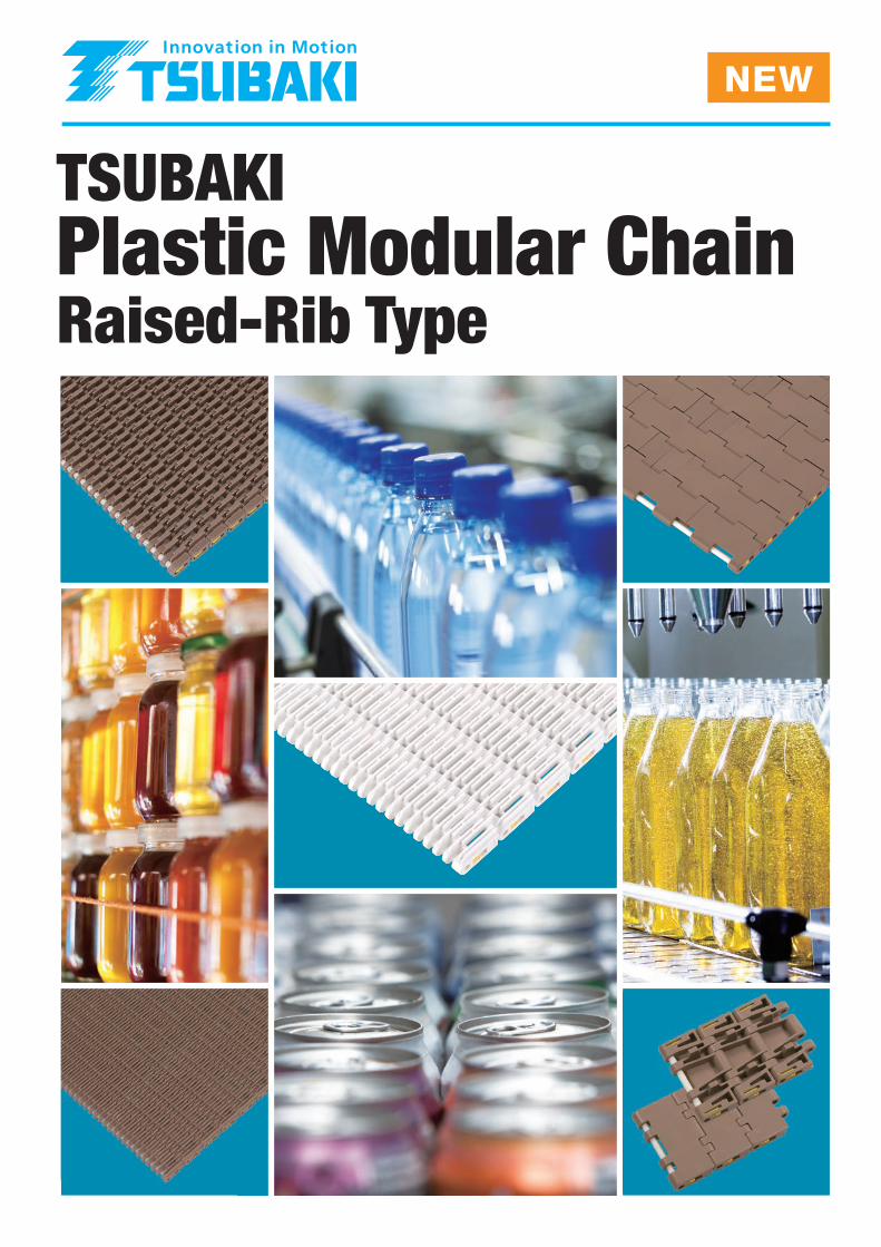
TSUBAKIPlastic Modular ChainRaised-Rib Type
NEW

WT3835-K Chain
WT3835G-M Chain
FeaturesA slide stopper pin retention system allows the modules to be disconnected and reconnected easily using a screwdriver.
SpecificationsChain type: Closed type, straight runningChain pitch: 38.1mmChain width: 152.4mm (min. width); chain width can be expanded in units of 76.2mmChain material: LFB (Low Friction/Wear Resistant), NLF (Low Friction), HTW (High Temperature)
ApplicationsMass handling conveyors
Raised-Rib Type—The Newest Member of the Tsubaki Plastic Modular Chain Line-up
Raised-Rib Type—The Newest Member of the Tsubaki Plastic Modular Chain Line-upRaised-rib Plastic Modular Chain works in combination with transfer plates to
eliminate the gap that occurs at transfer points (see illustration at right).
It prevents conveyed items from becoming entangled or snagged, providing for
smooth conveyance.
Raised-rib Plastic Modular Chain works in combination with transfer plates to
eliminate the gap that occurs at transfer points (see illustration at right).
It prevents conveyed items from becoming entangled or snagged, providing for
smooth conveyance.
New expanded line-up of versatile 38.1mm-pitch Plastic Modular Chain. Now more than ever, Tsubaki offers the Plastic Modular Chain that will meet your needs.
Newly introduced 38.1mm-pitch closed-type Plastic Modular Chain provides even greater versatility. Models are available with float-prevention tabs for use on inclined and vertical vacuum conveyors.
Newly available, highly versatile 38.1mm-pitch Plastic Modular Chain with fixed 82.6mm width and tab guide attachments. Ideal for conveyors such as single filers where adjacent chains are traveling at different speeds.
FeaturesLine-up is based on WT3835-K links having a fixed width (82.6mm). A slide stopper pin retention system allows the modules to be disconnected and reconnected easily using a screwdriver.
SpecificationsChain type: Closed type, straight runningChain pitch: 38.1mmChain width: 82.6mm (fixed width)Chain material: LFB (Low Friction/Wear Resistant), NLF (Low Friction), HTW (High Temperature)
ApplicationsSingle filers
Page 13
Pages 9–10
Closed Type
1
WT5707-K ChainWT1907-K Chain WT3827-K Chain
FeaturesRaised-rib type with highest allowable load. Recommended for conveying large amounts of containers, for example, through water spray baths.
SpecificationsChain type: Raised-rib type, straight runningChain pitch: 57.15mmChain width: 457.2mm (min. width); chain width can be expanded in units of 152.4mmChain material: LFB (Low Friction/Wear Resistant), HTW (High Temperature)
Applications• Accumulation conveyors• Water spray bath equipment
FeaturesRaised-rib type with a small chain pitch. Recommended for conveying small containers and rubber sheeting.
SpecificationsChain type: Raised-rib type, straight runningChain pitch: 19.05mmChain width: 228.6mm (min. width); chain width can be expanded in units of 76.2mmChain material: LFB (Low Friction/Wear Resistant), NLF (Low Friction), HTW (High Temperature)
Applications• Accumulation conveyors• Water spray bath equipment• Rubber sheet conveyance
Applications●●
●
Versatile type of chain that can be used in a wide range of applicationsIdeal in harsh conditions (high speeds, high loads) where chain elongation is accelerated, resulting in short chain replacement cyclesIdeal in high line pressure conditions where conveyed goods may be damaged
Applications●
●
Versatile chain that can be used in a wide range of applicationsIdeal in high line pressure conditions where conveyed goods may be damaged
Applications●●●
Chain for use in warmers and coolers in beverage plantsConveyors for batteriesSlightly inclined conveyors
Low-friction wear-resistant polyacetal chain links
Low-friction polyacetal chain links
Polypropylene chain links
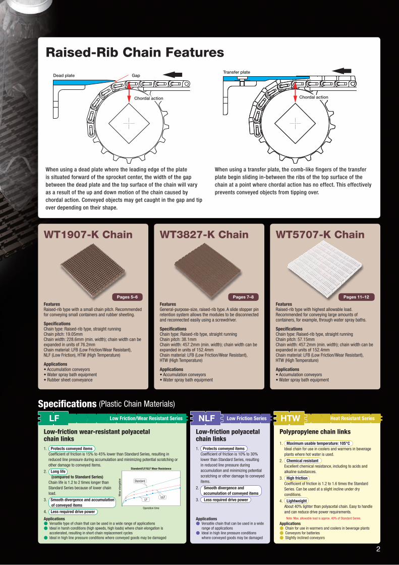
When using a dead plate where the leading edge of the plate is situated forward of the sprocket center, the width of the gap between the dead plate and the top surface of the chain will vary as a result of the up and down motion of the chain caused by chordal action. Conveyed objects may get caught in the gap and tip over depending on their shape.
When using a transfer plate, the comb-like fingers of the transfer plate begin sliding in-between the ribs of the top surface of the chain at a point where chordal action has no effect. This effectively prevents conveyed objects from tipping over.
FeaturesGeneral-purpose-size, raised-rib type. A slide stopper pin retention system allows the modules to be disconnected and reconnected easily using a screwdriver.
SpecificationsChain type: Raised-rib type, straight runningChain pitch: 38.1mmChain width: 457.2mm (min. width); chain width can be expanded in units of 152.4mmChain material: LFB (Low Friction/Wear Resistant), HTW (High Temperature)
Applications• Accumulation conveyors• Water spray bath equipment
Pages 7–8Pages 5–6
Raised-Rib Chain Features
Specifications (Plastic Chain Materials)
Pages 11–12
1. Maximum usable temperature: 105°CIdeal chain for use in coolers and warmers in beverage plants where hot water is used.
2. Chemical resistantExcellent chemical resistance, including to acids and alkaline substances.
3. High frictionCoefficient of friction is 1.2 to 1.6 times the Standard Series. Can be used at a slight incline under dry conditions.
4. LightweightAbout 40% lighter than polyacetal chain. Easy to handle and can reduce drive power requirements.
1. Protects conveyed itemsCoefficient of friction is 10% to 30% lower than Standard Series, resulting in reduced line pressure during accumulation and minimizing potential scratching or other damage to conveyed items.
2. Smooth divergence and accumulation of conveyed items
3. Less required drive power
1. Protects conveyed itemsCoefficient of friction is 15% to 45% lower than Standard Series, resulting in reduced line pressure during accumulation and minimizing potential scratching or other damage to conveyed items.
2. Long life (compared to Standard Series)
Chain life is 1.2 to 2 times longer than Standard Series because of lower chain load.
3. Smooth divergence and accumulation of conveyed items
4. Less required drive power
Standard/LF/ULF Wear Resistance
Standard
LFULF
Operation time
Wea
r elo
ngat
ion
LF NLF HTWLow Friction/Wear Resistant Series Low Friction Series Heat Resistant Series
Note: Max. allowable load is approx. 40% of Standard Series.
Dead plate
Chordal action
GapTransfer plate
Chordal action Chordal actionChordal action
2
Clo
sed
Op
enN
etR
aise
d R
ibP
erfo
rate
d
Type Features Applicable Series
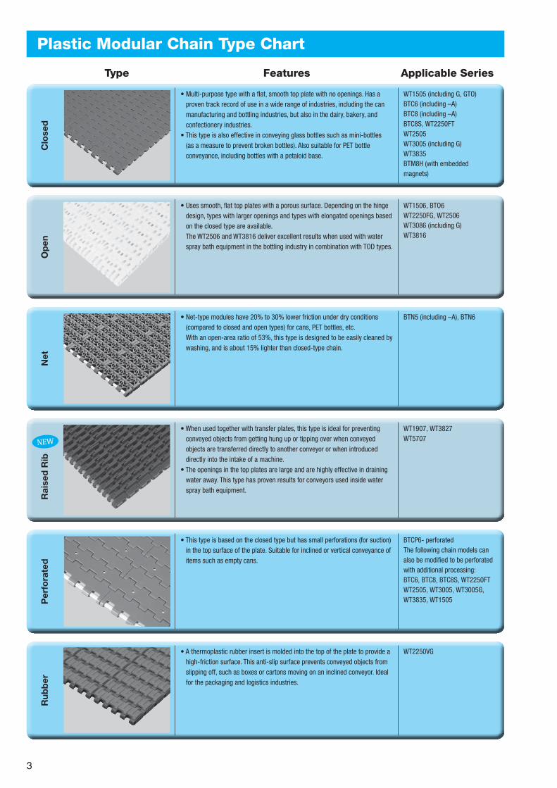
• Multi-purpose type with a flat, smooth top plate with no openings. Has a proven track record of use in a wide range of industries, including the can manufacturing and bottling industries, but also in the dairy, bakery, and confectionery industries.
• This type is also effective in conveying glass bottles such as mini-bottles (as a measure to prevent broken bottles). Also suitable for PET bottle conveyance, including bottles with a petaloid base.
• Uses smooth, flat top plates with a porous surface. Depending on the hinge design, types with larger openings and types with elongated openings based on the closed type are available. The WT2506 and WT3816 deliver excellent results when used with water spray bath equipment in the bottling industry in combination with TOD types.
• Net-type modules have 20% to 30% lower friction under dry conditions (compared to closed and open types) for cans, PET bottles, etc. With an open-area ratio of 53%, this type is designed to be easily cleaned by washing, and is about 15% lighter than closed-type chain.
• When used together with transfer plates, this type is ideal for preventing conveyed objects from getting hung up or tipping over when conveyed objects are transferred directly to another conveyor or when introduced directly into the intake of a machine.
• The openings in the top plates are large and are highly effective in draining water away. This type has proven results for conveyors used inside water spray bath equipment.
• This type is based on the closed type but has small perforations (for suction) in the top surface of the plate. Suitable for inclined or vertical conveyance of items such as empty cans.
WT1505 (including G, GTO)BTC6 (including –A)BTC8 (including –A)BTC8S, WT2250FTWT2505WT3005 (including G)WT3835BTM8H (with embedded magnets)
WT1506, BTO6WT2250FG, WT2506WT3086 (including G)WT3816
BTN5 (including –A), BTN6
WT1907, WT3827WT5707
BTCP6- perforatedThe following chain models can also be modified to be perforated with additional processing:BTC6, BTC8, BTC8S, WT2250FTWT2505, WT3005, WT3005G, WT3835, WT1505
Plastic Modular Chain Type ChartR
ubb
er
• A thermoplastic rubber insert is molded into the top of the plate to provide a high-friction surface. This anti-slip surface prevents conveyed objects from slipping off, such as boxes or cartons moving on an inclined conveyor. Ideal for the packaging and logistics industries.
WT2250VG
NEW
3
Fixe
d W
idth
Wit
h Fl
oat
-P
reve
ntio
n Ta
bs
Wit
h Fl
ight
s
Type Features Applicable Series
• This type is matched to the standard plate width of Top Chain (also available with tab guide attachments). Ideal for use as replacement for Top Chain conveyors and for combiners (alignment conveyors).
• This type is equipped with float-prevention tabs. These attachments prevent the chain from floating up, and keep the chain securely in position in sections of the conveyor that are inclined from the horizontal.
• Flight attachments are mounted on the plates, spaced several links apart, to enable reliable conveyance for inclined conveyors or for conveyors submerged in water baths.
• Flight heights of 25.4mm, 50.8mm, and 76.2mm are available.
BTC4-M, WT1505G-MWT1515G-M, BTO8-MBTC8H-MBTM8H-M (with embedded magnets)WT2505-M, WT2505G-MWT3005G-M, WT3086G-MWT3835G-M
BTC6-T, WT3835-T
WT2250FT (with flights)WT2250FG (with flights)
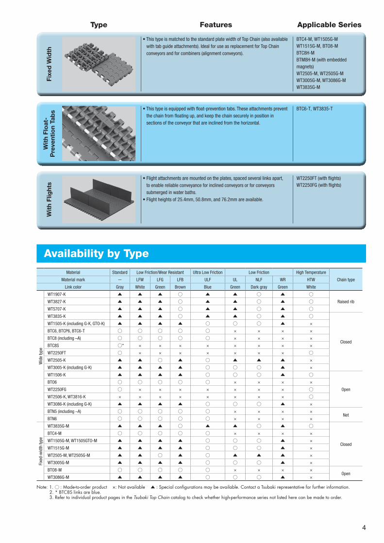
Availability by Type
Material Standard Low Friction/Wear Resistant Ultra Low Friction Low Friction High Temperature
Chain typeMaterial mark - LFW LFG LFB ULF UL NLF WR HTW
Link color Gray White Green Brown Blue Green Dark gray Green White
Wid
e ty
pe
WT1907-K ▲ ▲ ▲ ○ ▲ ▲ ○ ▲ ○Raised ribWT3827-K ▲ ▲ ▲ ○ ▲ ▲ ○ ▲ ○
WT5707-K ▲ ▲ ▲ ○ ▲ ▲ ○ ▲ ○WT3835-K ▲ ▲ ▲ ○ ▲ ▲ ○ ▲ ○
Closed
WT1505-K (including G-K, GTO-K) ▲ ▲ ▲ ▲ ○ ○ ○ ▲ ×
BTC6, BTCP6, BTC6-T ○ ○ ○ ○ ○ × × × ×
BTC8 (including –A) ○ ○ ○ ○ ○ × × × ×
BTC8S ○* × × × × × × × ×
WT2250FT ○ × × × × × × × ○WT2505-K ▲ ▲ ○ ▲ ○ ▲ ▲ ▲ ×
WT3005-K (including G-K) ▲ ▲ ▲ ▲ ○ ○ ○ ▲ ×
WT1506-K ▲ ▲ ▲ ▲ ○ ○ ○ ▲ ○
Open
BTO6 ○ ○ ○ ○ ○ × × × ×
WT2250FG ○ × × × × × × × ○WT2506-K, WT3816-K × × × × × × × × ○WT3086-K (including G-K) ▲ ▲ ▲ ▲ ○ ○ ○ ▲ ×
BTN5 (including –A) ○ ○ ○ ○ ○ × × × ×Net
BTN6 ○ ○ ○ ○ ○ × × × ×
Fixe
d-w
idth
type
WT3835G-M ▲ ▲ ▲ ○ ▲ ▲ ○ ▲ ○
Closed
BTC4-M ○ ○ ○ ○ ○ × × × ×
WT1505G-M, WT1505GTO-M ▲ ▲ ▲ ▲ ○ ○ ○ ▲ ×
WT1515G-M ▲ ▲ ▲ ▲ ○ ○ ○ ▲ ×
WT2505-M, WT2505G-M ▲ ▲ ○ ▲ ○ ▲ ▲ ▲ ×
WT3005G-M ▲ ▲ ▲ ▲ ○ ○ ○ ▲ ×
BTO8-M ○ ○ ○ ○ ○ × × × ×Open
WT3086G-M ▲ ▲ ▲ ▲ ○ ○ ○ ▲ ×
Note: 1. ○ : Made-to-order product ×: Not available ▲ : Special configurations may be available. Contact a Tsubaki representative for further information.2. * BTC8S links are blue.3. Refer to individual product pages in the Tsubaki Top Chain catalog to check whether high-performance series not listed here can be made to order.
4
Note: 1. Values for max. allowable load are at ambient temperature (20°C) and assume that tension acts uniformly over the entire chain width. Values for max. allowable load in the table above are for chain that is one meter (1m) in width. To calculate values for other chain widths, multiply the chain width in question by the max. allowable load for one-meter (1m) wide chain.
2. Operating temperature of (60) is for wet conditions. 3. Made-to-order product. 4. Contact a Tsubaki representative for chain specifications (materials) other than the above. 5. Max. allowable speed: 50 m/min.
Chain (Plastic Pins)
Note: 1. Standard chain width is 76.2mm (3 inches). Custom chain widths and widths greater than 1,524mm are available upon request. 2. Chain width X shown is a nominal width. Actual width range is +0
-0.7% at 20°C operating temperature. Chain width is subject to expansion or contraction with changes in temperature. Expansion/contraction rate is 0.00015/°C based on reference temperature of 20°C.
Chain type Chain pitch Chain type Chain width Chain material
WT 19 07 - K24 - LFB
Model Numbering
Note: Do not leave spaces between letters and symbols. Number denotes width in inches. Multiply the number by 25.4 to convert it into millimeters. Example: 24 x 25.4 = 609.6mm
Features
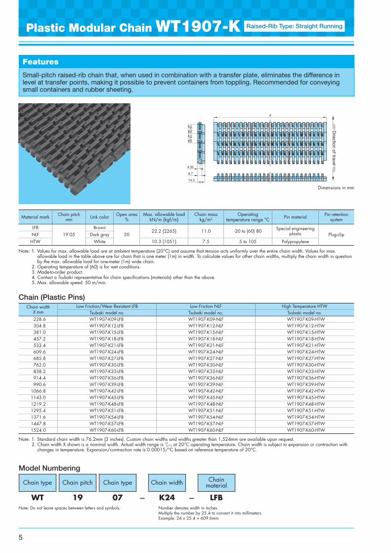
Small-pitch raised-rib chain that, when used in combination with a transfer plate, eliminates the difference in level at transfer points, making it possible to prevent containers from toppling. Recommended for conveying small containers and rubber sheeting.
Plastic Modular Chain WT1907-K Raised-Rib Type: Straight Running
X
19.0519.05
4.35
8.7
14.3
Direction of travel
Dimensions in mm
5
Material mark Chain pitchmm Link color Open area
%Max. allowable load
kN/m {kgf/m}Chain mass
kg/m2Operating
temperature range °C Pin material Pin retention system
LFB19.05
Brown20
22.2 {2265} 11.0 -20 to (60) 80 Special engineering plastic Plug-clipNLF Dark gray
HTW White 10.3 {1051} 7.5 5 to 105 Polypropylene
Chain width X mm
Low Friction/Wear Resistant LFB Low Friction NLF High Temperature HTWTsubaki model no. Tsubaki model no. Tsubaki model no.
228.6 WT1907-K09-LFB WT1907-K09-NLF WT1907-K09-HTW304.8 WT1907-K12-LFB WT1907-K12-NLF WT1907-K12-HTW381.0 WT1907-K15-LFB WT1907-K15-NLF WT1907-K15-HTW457.2 WT1907-K18-LFB WT1907-K18-NLF WT1907-K18-HTW533.4 WT1907-K21-LFB WT1907-K21-NLF WT1907-K21-HTW609.6 WT1907-K24-LFB WT1907-K24-NLF WT1907-K24-HTW685.8 WT1907-K27-LFB WT1907-K27-NLF WT1907-K27-HTW762.0 WT1907-K30-LFB WT1907-K30-NLF WT1907-K30-HTW838.2 WT1907-K33-LFB WT1907-K33-NLF WT1907-K33-HTW914.4 WT1907-K36-LFB WT1907-K36-NLF WT1907-K36-HTW990.6 WT1907-K39-LFB WT1907-K39-NLF WT1907-K39-HTW
1066.8 WT1907-K42-LFB WT1907-K42-NLF WT1907-K42-HTW1143.0 WT1907-K45-LFB WT1907-K45-NLF WT1907-K45-HTW1219.2 WT1907-K48-LFB WT1907-K48-NLF WT1907-K48-HTW1295.4 WT1907-K51-LFB WT1907-K51-NLF WT1907-K51-HTW1371.6 WT1907-K54-LFB WT1907-K54-NLF WT1907-K54-HTW1447.8 WT1907-K57-LFB WT1907-K57-NLF WT1907-K57-HTW1524.0 WT1907-K60-LFB WT1907-K60-NLF WT1907-K60-HTW
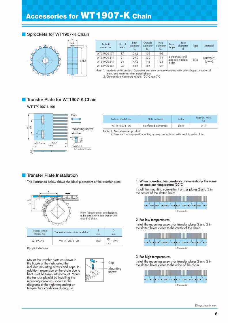
■ Sprockets for WT1907-K Chain
■ Transfer Plate for WT1907-K Chain
Note: 1. Made-to-order product.2. Two each of caps and mounting screws are included with each transfer plate.
Note: 1. Made-to-order product. Sprockets can also be manufactured with other shapes, number of teeth, and materials than noted above.
2. Operating temperature range: –20°C to 60°C
WT-TP1907-L190
Accessories for WT1907-K Chain
Do
Dp
DH
11.9
35
Mounting screw150
82.6
44.5
6.4
Cap
M6(P=1.0)Self-locking threads
15.5
2
φ11.7
50.8 139.7
190.5
Dimensions in mm
6
Tsubaki model no. Plate material Color Approx. mass kg
WT-TP1907-L190 Reinforced polyamide Black 0.17
Tsubakimodel no.
No. of teeth
Pitch diameter
DP
Outside diameter
DO
Hub diameter
DH
Bore shape
Bore diameter
dType Material
WT-S1900-17T 17 104.6 105 90Bore shape and size are made-to-order.
Solid UHMW-PE (green)
WT-S1900-21T 21 129.0 130 114WT-S1900-24T 24 147.3 148 133WT-S1900-25T 25 153.4 154 139
Dp: pitch diameter
Mount the transfer plate as shown in the figure at the right using the included mounting screws and caps. In addition, expansion of the chain due to heat must be taken into account. Mount the transfer plate(s) by installing the mounting screws as shown in the diagrams at the right depending on temperature conditions during use.
■ Transfer Plate InstallationThe illustration below shows the ideal placement of the transfer plate.
Note: Transfer plates are designed to be used only in conjunction with raised-rib chain.
1) When operating temperatures are essentially the same as ambient temperature (20°C)
Install the mounting screws for transfer plates 2 and 3 in the center of the slotted holes.
2) For low temperaturesInstall the mounting screws for transfer plates 2 and 3 in the slotted holes closer to the center of the chain.
3) For high temperaturesInstall the mounting screws for transfer plates 2 and 3 in the slotted holes closer to the edge of the chain.
Cap
Mountingscrew
Tsubaki chain model no. Tsubaki transfer plate model no.
B mm
D mm
WT1907-K WT-TP1907-L190 100Dp 2
+9.9
D
B
0 -0.8
1 12 2 33
Chain center
1 12 2 33
Chain center
1 12 2 33
Chain center
Note: 1. Standard chain width is 152.4mm (6 inches). Custom chain widths and widths greater than 1,524mm are available upon request. 2. Chain width X shown is a nominal width. Actual width range is +0
-0.7% at 20°C operating temperature. Chain width is subject to expansion or contraction with changes in temperature. Expansion/contraction rate is 0.00015/°C based on reference temperature of 20°C.
Note: 1. Values for max. allowable load are at ambient temperature (20°C) and assume that tension acts uniformly over the entire chain width. Values for max. allowable load in the table above are for chain that is one meter (1m) in width. To calculate values for other chain widths, multiply the chain width in question by the max. allowable load for one-meter (1m) wide chain.
2. Operating temperature of (60) is for wet conditions. 3. Made-to-order product. 4. Contact a Tsubaki representative for chain specifications (materials) other than the above. 5. Max. allowable speed: 50 m/min.
Chain (Plastic Pins)
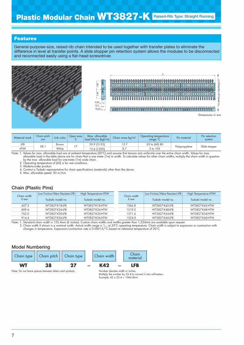
Features
General-purpose-size, raised-rib chain intended to be used together with transfer plates to eliminate the difference in level at transfer points. A slide stopper pin retention system allows the modules to be disconnected and reconnected easily using a flat-head screwdriver.
Chain type Chain pitch Chain type Chain width Chain material
WT 38 27 - K42 - LFB
Model Numbering
Note: Do not leave spaces between letters and symbols. Number denotes width in inches. Multiply the number by 25.4 to convert it into millimeters. Example: 42 x 25.4 = 1066.8mm
Plastic Modular Chain WT3827-K Raised-Rib Type: Straight Running
X
38.1
6.35
12.7
19.05
Direction of travel
38.1
Dimensions in mm
7
Material mark Chain pitchmm Link color Open area
%Max. allowable
load kN/m {kgf/m} Chain mass kg/m2 Operating temperature range °C Pin material Pin retention
system
LFB38.1
Brown17
30.9 {3153} 12.7 -20 to (60) 80Polypropylene Slide stopper
HTW White 15.6 {1592} 8.7 5 to 105
Chain width X mm
Low Friction/Wear Resistant LFB High Temperature HTWChain width
X mm
Low Friction/Wear Resistant LFB High Temperature HTW
Tsubaki model no. Tsubaki model no. Tsubaki model no. Tsubaki model no.
457.2 WT3827-K18-LFB WT3827-K18-HTW 1066.8 WT3827-K42-LFB WT3827-K42-HTW609.6 WT3827-K24-LFB WT3827-K24-HTW 1219.2 WT3827-K48-LFB WT3827-K48-HTW762.0 WT3827-K30-LFB WT3827-K30-HTW 1371.6 WT3827-K54-LFB WT3827-K54-HTW914.4 WT3827-K36-LFB WT3827-K36-HTW 1524.0 WT3827-K60-LFB WT3827-K60-HTW
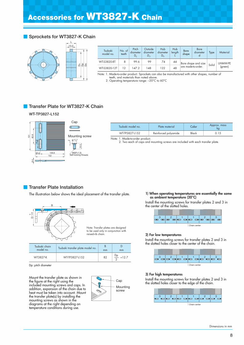
■ Sprockets for WT3827-K Chain
Note: 1. Made-to-order product. Sprockets can also be manufactured with other shapes, number of teeth, and materials than noted above.
2. Operating temperature range: –20°C to 60°C
Note: 1. Made-to-order product.2. Two each of caps and mounting screws are included with each transfer plate.
■ Transfer Plate for WT3827-K Chain
Accessories for WT3827-K Chain
WT-TP3827-L152
L
13.2
Do
Dp
DH
Dimensions in mm
6.4
82.6
151
25.4 126.6152
φ11.72
15.5
M6(P=1.0)Self-locking threads
Cap
Mounting screw
45.8
8
Tsubakimodel no.
No. of teeth
Pitch diameter
DP
Outside diameter
DO
Hub diameter
DH
Hub length
L
Bore shape
Bore diameter
dType Material
WT-S3820-8T 8 99.6 99 74 44 Bore shape and size are made-to-order. Solid UHMW-PE
(green)WT-S3820-12T 12 147.2 148 122 48
Tsubaki model no. Plate material Color Approx. mass kg
WT-TP3827-L152 Reinforced polyamide Black 0.15
Dp: pitch diameter
Mount the transfer plate as shown in the figure at the right using the included mounting screws and caps. In addition, expansion of the chain due to heat must be taken into account. Mount the transfer plate(s) by installing the mounting screws as shown in the diagrams at the right depending on temperature conditions during use.
■ Transfer Plate InstallationThe illustration below shows the ideal placement of the transfer plate. 1) When operating temperatures are essentially the same
as ambient temperature (20°C)Install the mounting screws for transfer plates 2 and 3 in the center of the slotted holes.
2) For low temperaturesInstall the mounting screws for transfer plates 2 and 3 in the slotted holes closer to the center of the chain.
3) For high temperaturesInstall the mounting screws for transfer plates 2 and 3 in the slotted holes closer to the edge of the chain.
Cap
Mountingscrew
Tsubaki chain model no. Tsubaki transfer plate model no.
B mm
D mm
WT3827-K WT-TP3827-L152 82Dp 2
+12.7
D
B
0 -0.8
1 12 2 33
Chain center
1 12 2 33
Chain center
1 12 2 33
Chain center
Note: Transfer plates are designed to be used only in conjunction with raised-rib chain.
Note: 1. Standard chain width is 76.2mm (3 inches). Custom chain widths and widths greater than 1,524mm are available upon request. 2. Chain width X shown is a nominal width. Actual width range is +0
-0.7% at 20°C operating temperature. Chain width is subject to expansion or contraction with changes in temperature. Expansion/contraction rate is 0.00015/°C based on reference temperature of 20°C.
Note: 1. Values for max. allowable load are at ambient temperature (20°C) and assume that tension acts uniformly over the entire chain width. Values for max. allowable load in the table above are for chain that is one meter (1m) in width. To calculate values for other chain widths, multiply the chain width in question by the max. allowable load for one-meter (1m) wide chain.
2. Operating temperature of (60) is for wet conditions. 3. Made-to-order product. 4. Contact a Tsubaki representative for chain specifications (materials) other than the above. 5. Max. allowable speed: 50 m/min.
Chain (Plastic Pins)
Features
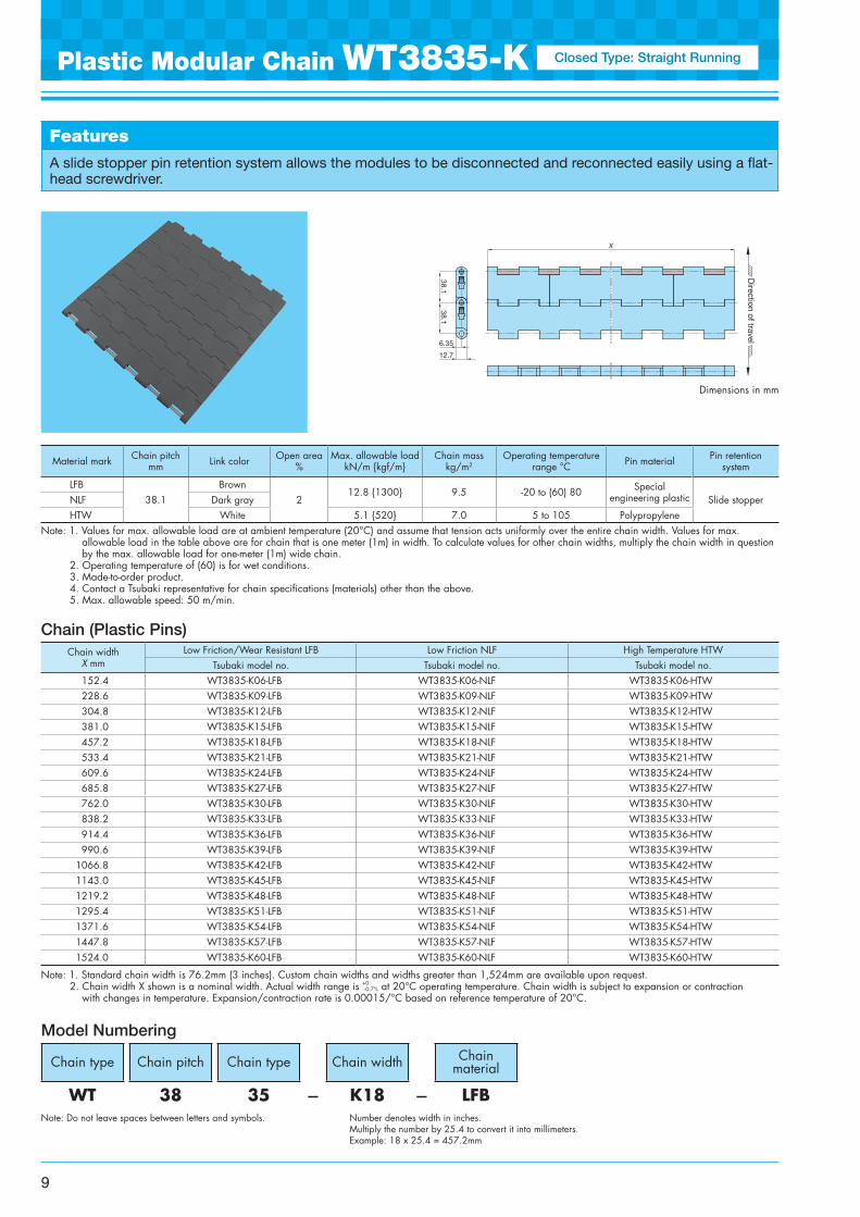
A slide stopper pin retention system allows the modules to be disconnected and reconnected easily using a flat-head screwdriver.
Chain type Chain pitch Chain type Chain width Chain material
WT 38 35 - K18 - LFB
Model Numbering
Note: Do not leave spaces between letters and symbols. Number denotes width in inches. Multiply the number by 25.4 to convert it into millimeters. Example: 18 x 25.4 = 457.2mm
Plastic Modular Chain WT3835-K Closed Type: Straight Running
X
38.1
12.7
6.35
Direction of travel
38.1
Dimensions in mm
9
Chain width X mm
Low Friction/Wear Resistant LFB Low Friction NLF High Temperature HTWTsubaki model no. Tsubaki model no. Tsubaki model no.
152.4 WT3835-K06-LFB WT3835-K06-NLF WT3835-K06-HTW228.6 WT3835-K09-LFB WT3835-K09-NLF WT3835-K09-HTW304.8 WT3835-K12-LFB WT3835-K12-NLF WT3835-K12-HTW381.0 WT3835-K15-LFB WT3835-K15-NLF WT3835-K15-HTW457.2 WT3835-K18-LFB WT3835-K18-NLF WT3835-K18-HTW533.4 WT3835-K21-LFB WT3835-K21-NLF WT3835-K21-HTW609.6 WT3835-K24-LFB WT3835-K24-NLF WT3835-K24-HTW685.8 WT3835-K27-LFB WT3835-K27-NLF WT3835-K27-HTW762.0 WT3835-K30-LFB WT3835-K30-NLF WT3835-K30-HTW838.2 WT3835-K33-LFB WT3835-K33-NLF WT3835-K33-HTW914.4 WT3835-K36-LFB WT3835-K36-NLF WT3835-K36-HTW990.6 WT3835-K39-LFB WT3835-K39-NLF WT3835-K39-HTW
1066.8 WT3835-K42-LFB WT3835-K42-NLF WT3835-K42-HTW1143.0 WT3835-K45-LFB WT3835-K45-NLF WT3835-K45-HTW1219.2 WT3835-K48-LFB WT3835-K48-NLF WT3835-K48-HTW1295.4 WT3835-K51-LFB WT3835-K51-NLF WT3835-K51-HTW1371.6 WT3835-K54-LFB WT3835-K54-NLF WT3835-K54-HTW1447.8 WT3835-K57-LFB WT3835-K57-NLF WT3835-K57-HTW1524.0 WT3835-K60-LFB WT3835-K60-NLF WT3835-K60-HTW
Material mark Chain pitchmm Link color Open area
%Max. allowable load
kN/m {kgf/m}Chain mass
kg/m2Operating temperature
range °C Pin material Pin retention system
LFB38.1
Brown2
12.8 {1300} 9.5 -20 to (60) 80 Special engineering plastic Slide stopperNLF Dark gray
HTW White 5.1 {520} 7.0 5 to 105 Polypropylene
■ Sprockets for WT3835-K/WT3835-T Chain
Note: 1. Made-to-order product. Sprockets can also be manufactured with other shapes, number of teeth, and materials than noted above.
2. Operating temperature range: –20°C to 60°C
Plastic Modular Chain WT3835-T and Sprockets
Note: 1. Standard product. 2. Operating temperature range: –20°C to 80°C 3. Bolt tightening torque: 5.7 N·m {0.58 kgf·m} 4. When assembling the halves of the sprocket, do not
mix the halves with halves from other sprockets. 5. Should not be subjected to extreme changes in
operating temperature.
• Molded split sprocket, reinforced polyamide
DH
Do
Dp
15.945
38.1
φDPφd
H
W
43
16
50
φDO
φDH
457.2
20
26.2
10
1518
.8
31.5
38.138.1
6.35
12.7
Direction of travel
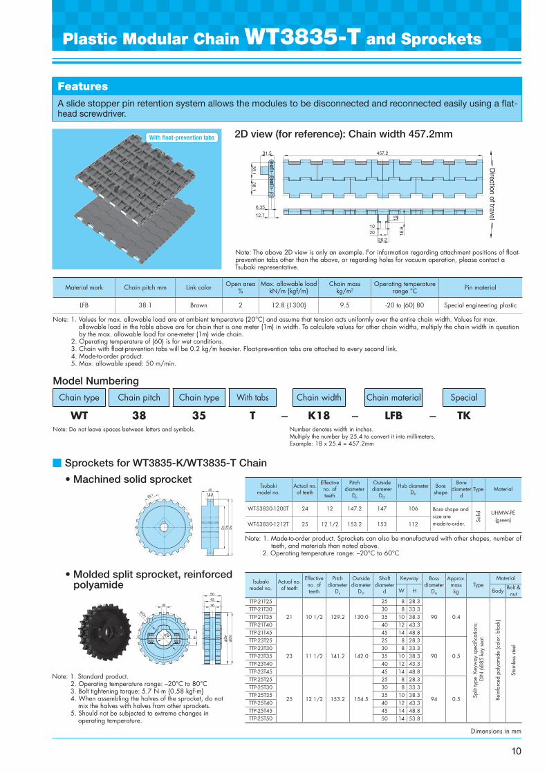
2D view (for reference): Chain width 457.2mm
Note: The above 2D view is only an example. For information regarding attachment positions of float-prevention tabs other than the above, or regarding holes for vacuum operation, please contact a Tsubaki representative.
Features
A slide stopper pin retention system allows the modules to be disconnected and reconnected easily using a flat-head screwdriver.
Material mark Chain pitch mm Link color Open area %
Max. allowable load kN/m {kgf/m}
Chain mass kg/m2
Operating temperature range °C Pin material
LFB 38.1 Brown 2 12.8 {1300} 9.5 -20 to (60) 80 Special engineering plastic
Note: 1. Values for max. allowable load are at ambient temperature (20°C) and assume that tension acts uniformly over the entire chain width. Values for max. allowable load in the table above are for chain that is one meter (1m) in width. To calculate values for other chain widths, multiply the chain width in question by the max. allowable load for one-meter (1m) wide chain.
2. Operating temperature of (60) is for wet conditions. 3. Chain with float-prevention tabs will be 0.2 kg/m heavier. Float-prevention tabs are attached to every second link. 4. Made-to-order product. 5. Max. allowable speed: 50 m/min.
Model Numbering
• Machined solid sprocket
Chain type Chain pitch Chain type With tabs Chain width Chain material Special
WT 38 35 T - K18 - LFB - TKNote: Do not leave spaces between letters and symbols. Number denotes width in inches.
Multiply the number by 25.4 to convert it into millimeters. Example: 18 x 25.4 = 457.2mm
With float-prevention tabs
Dimensions in mm
10
Tsubakimodel no.
Actual no. of teeth
Effective no. of teeth
Pitch diameter
DP
Outside diameter
DO
Hub diameter DH
Bore shape
Bore diameter
dType Material
WT-S3830-1200T 24 12 147.2 147 106 Bore shape and size are made-to-order. So
lid UHMW-PE (green)
WT-S3830-1212T 25 12 1/2 153.2 153 112
Tsubakimodel no.
Actual no. of teeth
Effective no. of teeth
Pitch diameter
DP
Outside diameter
DO
Shaft diameter
d
Keyway Boss diameter
DH
Approx. mass kg
TypeMaterial
W H Body Bolt & nut
TTP-21T25
21 10 1/2 129.2 130.0
25 8 28.3
90 0.4
Split
type
. Key
way
spe
cific
atio
ns:
DIN
688
5 ke
y se
at
Rein
forc
ed p
olya
mid
e (c
olor
: bla
ck)
Stai
nles
s ste
el
TTP-21T30 30 8 33.3TTP-21T35 35 10 38.3TTP-21T40 40 12 43.3TTP-21T45 45 14 48.8TTP-23T25
23 11 1/2 141.2 142.0
25 8 28.3
90 0.5TTP-23T30 30 8 33.3TTP-23T35 35 10 38.3TTP-23T40 40 12 43.3TTP-23T45 45 14 48.8TTP-25T25
25 12 1/2 153.2 154.5
25 8 28.3
94 0.5
TTP-25T30 30 8 33.3TTP-25T35 35 10 38.3TTP-25T40 40 12 43.3TTP-25T45 45 14 48.8TTP-25T50 50 14 53.8
Note: 1. Standard chain width is 152.4mm (6 inches). Custom chain widths and widths greater than 3,048mm are available upon request. 2. Chain width X shown is a nominal width. Actual width range is +0
-0.7% at 20°C operating temperature. Chain width is subject to expansion or contraction with changes in temperature. Expansion/contraction rate is 0.00015/°C based on reference temperature of 20°C.
Note: 1. Values for max. allowable load are at ambient temperature (20°C) and assume that tension acts uniformly over the entire chain width. Values for max. allowable load in the table above are for chain that is one meter (1m) in width. To calculate values for other chain widths, multiply the chain width in question by the max. allowable load for one-meter (1m) wide chain.
2. Operating temperature of (60) is for wet conditions. 3. Made-to-order product. 4. Contact a Tsubaki representative for chain specifications (materials) other than the above. 5. Max. allowable speed: 50 m/min.
Chain (Plastic Pins)
Features
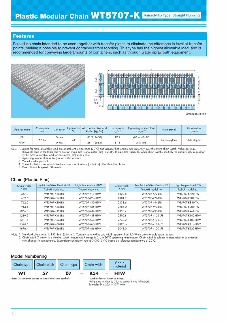
Raised-rib chain intended to be used together with transfer plates to eliminate the difference in level at transfer points, making it possible to prevent containers from toppling. This type has the highest allowable load, and is recommended for conveying large amounts of containers, such as through water spray bath equipment.
Chain type Chain pitch Chain type Chain width Chain material
WT 57 07 - K54 - HTW
Model Numbering
Note: Do not leave spaces between letters and symbols. Number denotes width in inches. Multiply the number by 25.4 to convert it into millimeters. Example: 54 x 25.4 = 1371.6mm
Plastic Modular Chain WT5707-K Raised-Rib Type: Straight Running
Dimensions in mm
57.15
X
9.1
18.2
24.6
Direction of travel
57.15
11
Material mark Chain pitchmm Link color Open area
%Max. allowable load
kN/m {kgf/m}Chain mass
kg/m2Operating temperature
range °C Pin material Pin retention system
LFB57.15
Brown23
43.9 {4480} 17.2 -20 to (60) 80Polypropylene Slide stopper
HTW White 26.1 {2663} 11.3 5 to 105
Chain width X mm
Low Friction/Wear Resistant LFB High Temperature HTW Chain width X mm
Low Friction/Wear Resistant LFB High Temperature HTW
Tsubaki model no. Tsubaki model no. Tsubaki model no. Tsubaki model no.
457.2 WT5707-K18-LFB WT5707-K18-HTW 1828.8 WT5707-K72-LFB WT5707-K72-HTW
609.6 WT5707-K24-LFB WT5707-K24-HTW 1981.2 WT5707-K78-LFB WT5707-K78-HTW
762.0 WT5707-K30-LFB WT5707-K30-HTW 2133.6 WT5707-K84-LFB WT5707-K84-HTW
914.4 WT5707-K36-LFB WT5707-K36-HTW 2286.0 WT5707-K90-LFB WT5707-K90-HTW
1066.8 WT5707-K42-LFB WT5707-K42-HTW 2438.4 WT5707-K96-LFB WT5707-K96-HTW
1219.2 WT5707-K48-LFB WT5707-K48-HTW 2590.8 WT5707-K102-LFB WT5707-K102-HTW
1371.6 WT5707-K54-LFB WT5707-K54-HTW 2743.2 WT5707-K108-LFB WT5707-K108-HTW
1524.0 WT5707-K60-LFB WT5707-K60-HTW 2895.6 WT5707-K114-LFB WT5707-K114-HTW
1676.4 WT5707-K66-LFB WT5707-K66-HTW 3048.0 WT5707-K120-LFB WT5707-K120-HTW
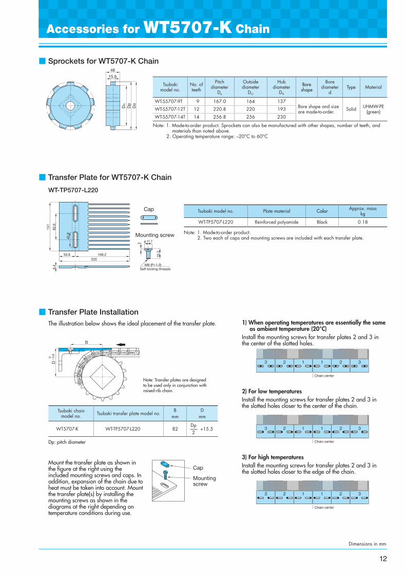
■ Sprockets for WT5707-K Chain
Note: 1. Made-to-order product. Sprockets can also be manufactured with other shapes, number of teeth, and materials than noted above.
2. Operating temperature range: –20°C to 60°C
■ Transfer Plate for WT5707-K Chain
WT-TP5707-L220
Note: 1. Made-to-order product.2. Two each of caps and mounting screws are included with each transfer plate.
Accessories for WT5707-K Chain
48
15.9
Dp
Do
DH
Dimensions in mm
82.6
50.8 169.2220
151
6.4
φ11.72
15.5
M6 (P=1.0)Self-locking threads
Cap
Mounting screw
45.8
12
Tsubaki model no.
No. of teeth
Pitchdiameter
DP
Outside diameter
DO
Hub diameter
DH
Bore shape
Bore diameter
dType Material
WT-S5707-9T 9 167.0 164 137Bore shape and size are made-to-order. Solid UHMW-PE
(green)WT-S5707-12T 12 220.8 220 193
WT-S5707-14T 14 256.8 256 230
Tsubaki model no. Plate material Color Approx. mass kg
WT-TP5707-L220 Reinforced polyamide Black 0.18
Dp: pitch diameter
Mount the transfer plate as shown in the figure at the right using the included mounting screws and caps. In addition, expansion of the chain due to heat must be taken into account. Mount the transfer plate(s) by installing the mounting screws as shown in the diagrams at the right depending on temperature conditions during use.
■ Transfer Plate InstallationThe illustration below shows the ideal placement of the transfer plate.
Note: Transfer plates are designed to be used only in conjunction with raised-rib chain.
1) When operating temperatures are essentially the same as ambient temperature (20°C)
Install the mounting screws for transfer plates 2 and 3 in the center of the slotted holes.
2) For low temperaturesInstall the mounting screws for transfer plates 2 and 3 in the slotted holes closer to the center of the chain.
3) For high temperaturesInstall the mounting screws for transfer plates 2 and 3 in the slotted holes closer to the edge of the chain.
Cap
Mountingscrew
Tsubaki chain model no. Tsubaki transfer plate model no.
B mm
D mm
WT5707-K WT-TP5707-L220 82Dp 2
+15.5
D
B
0 -0.8
1 12 2 33
Chain center
1 12 2 33
Chain center
1 12 2 33
Chain center
Note: 1. Made-to-order product. 2. Operating temperature of (60) is for wet conditions. 3. Contact a Tsubaki representative for chain specifications (materials) other than the above. 4. Use WT-S3830 machined solid sprocket (on page 10). Molded split sprockets cannot be used.
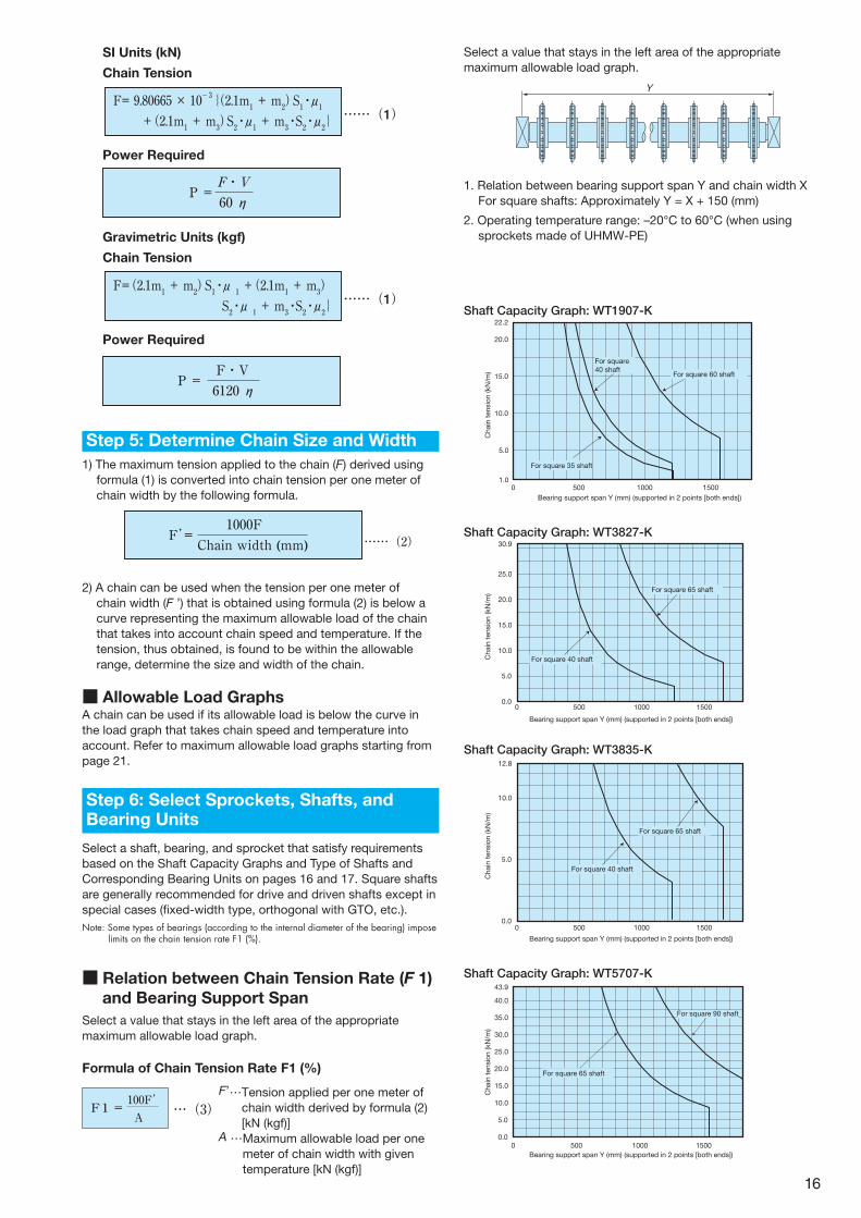
■ Idler Wheel for WT3835G-M Chain
Features
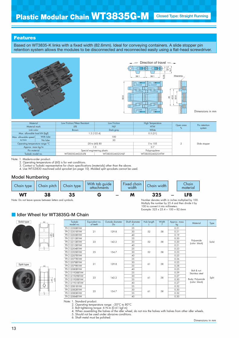
Based on WT3835-K links with a fixed width (82.6mm). Ideal for conveying containers. A slide stopper pin retention system allows the modules to be disconnected and reconnected easily using a flat-head screwdriver.
Chain type Chain pitch Chain type With tab guide attachments
Fixed chain width Chain width Chain
material
WT 38 35 G - M 325 - LFB
Model Numbering
Note: Do not leave spaces between letters and symbols. Number denotes width in inches multiplied by 100. Multiply the number by 25.4 and then divide it by 100 to convert it into millimeters. Example: 325 x 25.4 ÷ 100 = 82.6mm
Plastic Modular Chain WT3835G-M Closed Type: Straight Running
Dimensions in mm
Dimensions in mm
Tsubaki model no.
Equivalent no. of teeth
Outside diameter Do
Shaft diameter d
Hub length L
WidthT
Approx. mass kg Material Type
TP-C12200BT-IW21 129.8
2552 58
0.21
Polyamide (color: black) Solid
TP-C12201BT-IW 30 0.21TP-C12203BT-IW 40 0.19TP-C12212BT-IW
23 142.225
52 580.20
TP-C12213BT-IW 30 0.20TP-C12215BT-IW 40 0.21TP-C12204BT-IW
25 154.725
52 580.23
TP-C12205BT-IW 30 0.23TP-C12207BT-IW 40 0.25TP-C12077BT-IW
21 129.8
25
61 58
0.26
Bolt & nut: Stainless steel
Body: Polyamide (color: black)
Split
TP-C12078BT-IW 30 0.25TP-C12079BT-IW 35 0.28TP-C12080BT-IW 40 0.25TP-C121928BT-IW
23 142.2
25
61 58
0.29TP-C121929BT-IW 30 0.27TP-C121930BT-IW 35 0.30TP-C121931BT-IW 40 0.27TP-C12081BT-IW
25 154.7
25
61 58
0.32TP-C12082BT-IW 30 0.30TP-C12083BT-IW 35 0.32TP-C12084BT-IW 40 0.30
Note: 1. Standard product. 2. Operating temperature range: –20°C to 80°C 3. Bolt tightening torque: 6 N·m {0.61 kgf·m} 4. When assembling the halves of the idler wheel, do not mix the halves with halves from other idler wheels. 5. Should not be used under abrasive conditions. 6. Shaft metal must be polished.
φDo
Tφd
φd
44
L
φd
φd
44
φDo
LT
Solid type
Split type
38.1 38.1
82.6
32.6
42.8
6.35
12.7
19.7
45
Direction of travel
Wearstrip
13
Material Low Friction/Wear Resistant Low Friction High TemperatureOpen area
%Pin retention
systemMaterial mark LFB NLF HTWLink color Brown Dark gray White
Max. allowable load kN {kgf} 1.2 {122.4} 0.5 {51}
2 Slide stopper
Max. allowable speed m/min
With lube 100No lube 50
Operating temperature range °C -20 to (60) 80 5 to 105Approx. mass kg/m 1.0 0.7
Pin material Special engineering plastic PolypropyleneTsubaki model no. WT3835G-M325-LFB WT3835G-M325-NLF WT3835G-M325-HTW
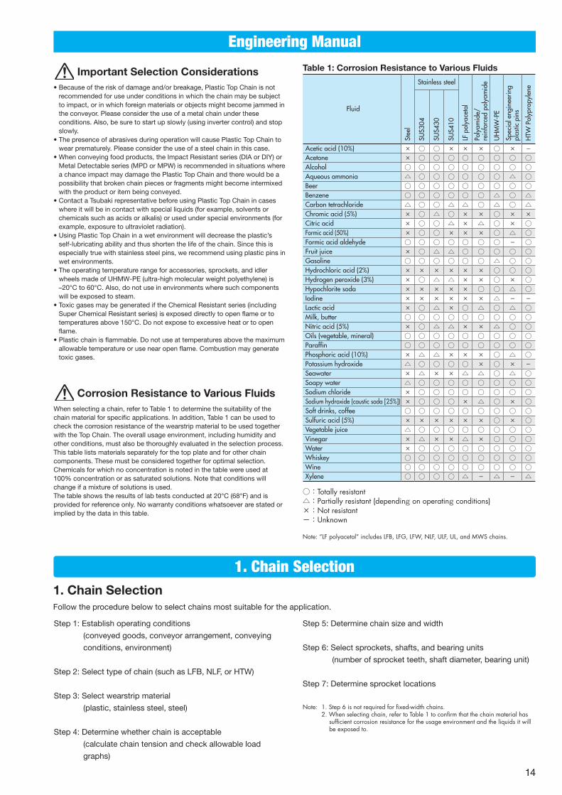
Table 1: Corrosion Resistance to Various Fluids
Fluid
Stee
l
Stainless steel
LF p
olya
ceta
l
Poly
amid
e/re
info
rced
pol
yam
ide
UH
MW
-PE
Spec
ial e
ngin
eerin
g pl
astic
pin
s
HTW
Pol
ypro
pyle
ne
SUS3
04
SUS4
30
SUS4
10
Acetic acid (10%) × ○ ○ × × × ○ × -Acetone × ○ ○ ○ ○ ○ ○ ○ ○Alcohol ○ ○ ○ ○ ○ ○ ○ ○ ○Aqueous ammonia △ ○ ○ ○ ○ ○ ○ △ ○Beer ○ ○ ○ ○ ○ ○ ○ ○ ○Benzene ○ ○ ○ ○ ○ ○ △ ○ △Carbon tetrachloride △ ○ ○ △ △ ○ △ ○ △Chromic acid (5%) × ○ △ ○ × × ○ × ×Citric acid × ○ ○ △ × △ ○ × ○Formic acid (50%) × ○ ○ × × × ○ △ ○Formic acid aldehyde ○ ○ ○ ○ ○ ○ ○ - ○Fruit juice × ○ △ △ ○ ○ ○ ○ ○Gasoline ○ ○ ○ ○ ○ ○ △ ○ ○Hydrochloric acid (2%) × × × × × × ○ ○ ○Hydrogen peroxide (3%) × ○ △ △ × × ○ × ○Hypochlorite soda × × × × × ○ ○ △ ○Iodine × × × × × × △ - -Lactic acid × ○ △ × ○ △ ○ △ ○Milk, butter ○ ○ ○ ○ ○ ○ ○ ○ ○Nitric acid (5%) × ○ △ △ × × △ ○ ○Oils (vegetable, mineral) ○ ○ ○ ○ ○ ○ ○ ○ ○Paraffin ○ ○ ○ ○ ○ ○ ○ ○ ○Phosphoric acid (10%) × △ △ × × × ○ △ ○Potassium hydroxide △ ○ ○ ○ ○ × ○ × -Seawater × △ × × △ △ ○ △ ○Soapy water △ ○ ○ ○ ○ ○ ○ ○ ○Sodium chloride × ○ ○ ○ ○ ○ ○ ○ ○Sodium hydroxide (caustic soda [25%]) × ○ ○ ○ × △ ○ × ○Soft drinks, coffee ○ ○ ○ ○ ○ ○ ○ ○ ○Sulfuric acid (5%) × × × × × × ○ × ○Vegetable juice △ ○ ○ ○ ○ ○ ○ ○ ○Vinegar × △ × × △ × ○ ○ ○Water × ○ ○ ○ ○ ○ ○ ○ ○Whiskey ○ ○ ○ ○ ○ ○ ○ ○ ○Wine ○ ○ ○ ○ ○ ○ ○ ○ ○Xylene ○ ○ ○ ○ △ - △ - △
○:Totally resistant△:Partially resistant (depending on operating conditions)×:Not resistant-:Unknown
Note: “LF polyacetal” includes LFB, LFG, LFW, NLF, ULF, UL, and MWS chains.
Important Selection Considerations• Because of the risk of damage and/or breakage, Plastic Top Chain is not
recommended for use under conditions in which the chain may be subject to impact, or in which foreign materials or objects might become jammed in the conveyor. Please consider the use of a metal chain under these conditions. Also, be sure to start up slowly (using inverter control) and stop slowly.
• The presence of abrasives during operation will cause Plastic Top Chain to wear prematurely. Please consider the use of a steel chain in this case.
• When conveying food products, the Impact Resistant series (DIA or DIY) or Metal Detectable series (MPD or MPW) is recommended in situations where a chance impact may damage the Plastic Top Chain and there would be a possibility that broken chain pieces or fragments might become intermixed with the product or item being conveyed.
• Contact a Tsubaki representative before using Plastic Top Chain in cases where it will be in contact with special liquids (for example, solvents or chemicals such as acids or alkalis) or used under special environments (for example, exposure to ultraviolet radiation).
• Using Plastic Top Chain in a wet environment will decrease the plastic’s self-lubricating ability and thus shorten the life of the chain. Since this is especially true with stainless steel pins, we recommend using plastic pins in wet environments.
• The operating temperature range for accessories, sprockets, and idler wheels made of UHMW-PE (ultra-high molecular weight polyethylene) is –20°C to 60°C. Also, do not use in environments where such components will be exposed to steam.
• Toxic gases may be generated if the Chemical Resistant series (including Super Chemical Resistant series) is exposed directly to open flame or to temperatures above 150°C. Do not expose to excessive heat or to open flame.
• Plastic chain is flammable. Do not use at temperatures above the maximum allowable temperature or use near open flame. Combustion may generate toxic gases.
Corrosion Resistance to Various FluidsWhen selecting a chain, refer to Table 1 to determine the suitability of the chain material for specific applications. In addition, Table 1 can be used to check the corrosion resistance of the wearstrip material to be used together with the Top Chain. The overall usage environment, including humidity and other conditions, must also be thoroughly evaluated in the selection process. This table lists materials separately for the top plate and for other chain components. These must be considered together for optimal selection. Chemicals for which no concentration is noted in the table were used at 100% concentration or as saturated solutions. Note that conditions will change if a mixture of solutions is used. The table shows the results of lab tests conducted at 20°C (68°F) and is provided for reference only. No warranty conditions whatsoever are stated or implied by the data in this table.
1. Chain SelectionFollow the procedure below to select chains most suitable for the application.
Step 1: Establish operating conditions
(conveyed goods, conveyor arrangement, conveying
conditions, environment)
Step 2: Select type of chain (such as LFB, NLF, or HTW)
Step 3: Select wearstrip material
(plastic, stainless steel, steel)
Step 4: Determine whether chain is acceptable
(calculate chain tension and check allowable load
graphs)
Step 5: Determine chain size and width
Step 6: Select sprockets, shafts, and bearing units
(number of sprocket teeth, shaft diameter, bearing unit)
Step 7: Determine sprocket locations
Note: 1. Step 6 is not required for fixed-width chains. 2. When selecting chain, refer to Table 1 to confirm that the chain material has
sufficient corrosion resistance for the usage environment and the liquids it will be exposed to.
14
1. Chain Selection
Engineering Manual
S1 S2
Conveyance Accumulation
Note: Formulas are given for both SI units and gravimetric units. When calculating the chain tension (F), gravimetric weight
units (kgf) have the same value as SI mass units (kg).
F = Chain tension kN {kgf}m1 = Chain mass (kg/m)
How to calculate chain mass: Calculate the chain mass per 1-meter unit of length. When Amm is the chain width being considered, m1 = chain mass (value from catalog [kg/m2]) × A/1000
S1 = Length of conveyance section (m)m2 = Mass of conveyed goods (kg/m)S2 = Length of accumulation section (m)m3 = Mass of accumulated goods (kg/m)μ1 = Coefficient of dynamic friction between chain and
wearstrip μ1 = Coefficient of dynamic friction between conveyed
goods and accumulation section P = Power required (kw)V = Chain speed (m/min)η = Mechanical transmission efficiency for drive unit
Note: For fixed-width chains, follow the chain tension calculation for Plastic Top Chain (see page 9 of the Tsubaki Top Chain Engineering Manual [catalog no. ME12Y2]) or contact a Tsubaki representative.
1) Calculate the tension acting on the chain and required power (general-purpose conveyor)
Note: For special conveyors (pasteurizers, warmers, coolers), see page 38 of the Tsubaki Top Chain Engineering Manual (catalog no. ME12Y2) or contact a Tsubaki representative.
1) Conveyed goods
① Material of conveyed goods
② Mass per conveyed item
③ Shape and dimensions2) Conveyor arrangement
① Conveyor length and width
② Conveyor layout
③ Space limitations3) Other conditions
① Conveying capacity
② Interval/spacing between goods to be conveyed
③ Conveying speed
④ Lubrication
⑤ Goods accumulated or not4) Environment
① Temperature
② Corrosive conditions including the presence of chemicals, water, and high humidity
③ Abrasive conditions including the presence of glass, paint chips, metal powder, sand, etc.
(See Table 1 Corrosion Resistance to Various Fluids on
page 14.)
④ Exposure to ultraviolet radiation
Step 1: Establish Operating Conditions
Step 2: Select Type of ChainDetermine the type of chain to be used (chain type, pitch, and material) based on operating environment (ambient temperature and necessity of corrosion resistance) and application.
Note: 1. See the page for each individual product regarding chain types and the temperature levels and environments for which they are acceptable. 2. See page 14 for corrosion resistance.
• UHMW-PE• White or green
Solidur (P plastic rail)
M plastic rail,SJ-CNO
PMWplastic rail
• Most commonly used wearstrip• Machined or extruded• Recommended for plastic chains used under wet conditions
• Special polyamide• Blue (M plastic rail), gray (SJ-NCO)
• Specifically designed for dry use• Wear resistant• Machined
• Low friction, wear resistant UHMW-PE• White
• Lower friction and more wear resistant than P plastic rail• Machined
FeaturesMaterial, Color
Step 3: Select Wearstrip Material
Note: 1. See the page for each individual product regarding chain types and the temperature levels and environments for which they are acceptable. 2. See page 14 for corrosion resistance.
Note: Operating temperature range Solidur (P plastic rail), PMW plastic rail: –20°C to 60°C M plastic rail, SJ-CNO: –20°C to 80°C
Chain typeWearstrip material
No lube With lubeAbrasives
No Yes No Yes
Plastic modular chain• Straight running
Stainless steel B D A A
Steel A C B B
Solidur (P plastic rail) D × A ×
PMW plastic rail B × A ×
M plastic rail, SJ-CNO A × × ×
A: Most recommended B: Highly recommended C: Recommended D: Acceptable ×: Inappropriate
Note: 1. The coefficients of friction listed above are for room temperature (50°C or less); for high temperatures exceeding 50°C, use 0.35.
2. This friction coefficient data is based on experiments conducted by Tsubaki. Contamination on the chain, the shape of the bottom surface of conveyed goods, and other factors will cause slight differences in friction coefficient values. In particular, because the shape of the bottom surface, the type of paper material, etc., of paper packs and paper-based beverage containers may produce significant differences in friction coefficient values, we recommend that the coefficient of friction be measured for each type of conveyed item. Use the values given in the table above to calculate chain tension.
3. M plastic rails and SJ-NCO are specifically designed for dry conditions. 4. For lubrication with water, the friction coefficient may be significantly larger
than the values given in the table above depending on the type of conveyed item. In addition, adhesion may occur.
Coefficient of Dynamic Friction between Chain and Other Materials(μ1, μ2)
Other material Lubrication LFB, NLF HTWSolidur (P plastic rail), M
plastic railDry, water 0.20 0.30
Soapy water, oil 0.13 0.20PMW plastic rail,
SJ-CNODry, water 0.15 -
Soapy water, oil 0.12 -Steel,
Stainless steelDry, water 0.20 0.32
Soapy water, oil 0.15 0.20
Metallic cansDry, water 0.20 0.35
Soapy water, oil 0.13 0.20
Glass bottlesDry, water 0.14 0.22
Soapy water, oil 0.14 0.10
Plastic containersDry, water 0.17 0.30
Soapy water, oil 0.13 0.20
Paper packagesDry, water 0.29 0.35
Soapy water, oil 0.21 -
Step 4: Calculate Chain Tension
15
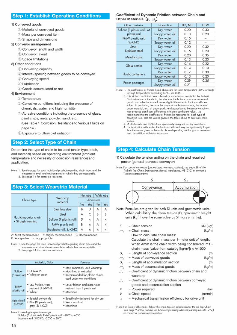
Select a value that stays in the left area of the appropriate maximum allowable load graph.
Y
1. Relation between bearing support span Y and chain width X For square shafts: Approximately Y = X + 150 (mm)
2. Operating temperature range: –20°C to 60°C (when using sprockets made of UHMW-PE)
1.0
20.0
5.0
10.0
22.2
15.0
500 1000 15000
For square 35 shaft
For square40 shaft
For square 60 shaft
Cha
in t
ensi
on (k
N/m
)
Bearing support span Y (mm) (supported in 2 points [both ends])
0.0
5.0
10.0
15.0
20.0
25.0
30.9
For square 40 shaft
For square 65 shaft
500 1000 15000
Cha
in t
ensi
on (k
N/m
)
Bearing support span Y (mm) (supported in 2 points [both ends])
0.0
5.0
10.0
500 1000 15000
12.8
For square 40 shaft
For square 65 shaft
Cha
in t
ensi
on (k
N/m
)
Bearing support span Y (mm) (supported in 2 points [both ends])
0.0
5.0
10.0
15.0
20.0
25.0
30.0
35.0
40.0
43.9
For square 90 shaft
For square 65 shaft
Cha
in t
ensi
on (k
N/m
)
Bearing support span Y (mm) (supported in 2 points [both ends])500 1000 15000
Shaft Capacity Graph: WT1907-K
Shaft Capacity Graph: WT3827-K
Shaft Capacity Graph: WT3835-K
Shaft Capacity Graph: WT5707-K
SI Units (kN)
Chain Tension
F= 9.80665 × 10⁻³{(2.1m1 + m2)S1・μ1
+(2.1m1 + m3)S2・μ1 + m3・S2・μ2 }……(1)
Power Required
P =F・V
60 η
Gravimetric Units (kgf)
Chain Tension
F=(2.1m1 + m2)S1・μ 1 +(2.1m1 + m3)S2・μ 1 + m3・S2・μ2 }
……(1)
Power Required
P = F・V
6120 η
■ Allowable Load GraphsA chain can be used if its allowable load is below the curve in the load graph that takes chain speed and temperature into account. Refer to maximum allowable load graphs starting from page 21.
1) The maximum tension applied to the chain (F) derived using formula (1) is converted into chain tension per one meter of chain width by the following formula.
F’= 1000F
Chain width (mm) ……(2)
2) A chain can be used when the tension per one meter of chain width (F ’) that is obtained using formula (2) is below a curve representing the maximum allowable load of the chain that takes into account chain speed and temperature. If the tension, thus obtained, is found to be within the allowable range, determine the size and width of the chain.
Step 5: Determine Chain Size and Width
Select a shaft, bearing, and sprocket that satisfy requirements based on the Shaft Capacity Graphs and Type of Shafts and Corresponding Bearing Units on pages 16 and 17. Square shafts are generally recommended for drive and driven shafts except in special cases (fixed-width type, orthogonal with GTO, etc.).Note: Some types of bearings (according to the internal diameter of the bearing) impose limits on the chain tension rate F1 (%).
■ Relation between Chain Tension Rate (F 1) and Bearing Support SpanSelect a value that stays in the left area of the appropriate maximum allowable load graph.
Step 6: Select Sprockets, Shafts, and Bearing Units
Formula of Chain Tension Rate F1 (%)
…(3)F’… Tension applied per one meter of
chain width derived by formula (2) [kN (kgf)]
A … Maximum allowable load per one meter of chain width with given temperature [kN (kgf)]
F1 = 100F’A
16
WT-S3830-1200T, WT-S3830-1212T (square 40 bore)
Shafttype
Bearing unit Limitation onchain tension
rate (F1)Bearing
ID Pillow Diamond flange Square flange
SUS304
Square 40polishedsteel bar
φ 25 UCP205 TP-C54205,59205 TP-C50205,55205 Applies only when 1.0 kN or lessUCFL205 UCF205
φ 30 UCP206 UCFL206 TP-C50206,55206 Applies only when 2.5 kN or lessUCF206
φ 35 UCP207 UCFL207 TP-C50207,55207 Applies only when 6.0 kN or lessUCF207
φ 40 UCP208 UCFL208 TP-C50208,55208 Applies only when 12.7 kN or lessUCF208
WT-S3820-8T (square 40 bore)
Shafttype
Bearing unit Limitation onchain tension
rate (F1)Bearing
ID Pillow Diamond flange Square flange
SUS304
Square 40polishedsteel bar
φ 25 UCP205TP-C54205,59205 TP-C50205,55205 Applies only when
1.5 kN or lessUCFL205 UCF205
φ 30 UCP206 UCFL206TP-C50206,55206 Applies only when
4.5 kN or lessUCF206
φ 35 UCP207 UCFL207TP-C50207,55207 Applies only when
13.5 kN or lessUCF207
φ 40 UCP208 UCFL208TP-C50208,55208 Applies only when
30.9 kN or lessUCF208
WT-S3820-12T (square 40 bore)
Shafttype
Bearing unit Limitation onchain tension
rate (F1)Bearing
ID Pillow Diamond flange Square flange
SUS304
Square 40polishedsteel bar
φ 25 UCP205TP-C54205,59205 TP-C50205,55205 Applies only when
1.5 kN or lessUCFL205 UCF205
φ 30 UCP206 UCFL206TP-C50206,55206 Applies only when
1.5 kN or lessUCF206
φ 35 UCP207 UCFL207TP-C50207,55207 Applies only when
6.0 kN or lessUCF207
φ 40 UCP208 UCFL208TP-C50208,55208 Applies only when
15.0 kN or lessUCF208
WT-S3830-1200T, WT-S3830-1212T (square 65 bore)
Shafttype
Bearing unit Limitation onchain tension
rate (F1)Bearing
ID Pillow Diamond flange Square flange
SUS304S45CSS400
Square 65polishedsteel bar
φ 35 UCP207 UCFL207 TP-C50207,55207 Applies only when 2.5 kN or lessUCF207
φ 40 UCP208 UCFL208 TP-C50208,55208 Applies only when 3.5 kN or lessUCF208
φ 45 UCP209 UCFL209 UCF209 Applies only when 5.5 kN or less
φ 50 UCP210 UCFL210 UCF210 Applies only when 7.5 kN or less
φ 55 UCP211 UCFL211 UCF211 Applies only when 12.7 kN or lessφ 60 UCP212 UCFL212 UCF212
WT-S3820-12T (square 65 bore)
Shafttype
Bearing unit Limitation onchain tension
rate (F1)Bearing
ID Pillow Diamond flange Square flange
SUS304S45CSS400
Square 65polishedsteel bar
φ 35 UCP207 UCFL207TP-C50207,55207 Applies only when
1.5 kN or lessUCF207
φ 40 UCP208 UCFL208TP-C50208,55208 Applies only when
3.0 kN or lessUCF208
φ 45 UCP209 UCFL209 UCF209 Applies only when 4.5 kN or less
φ 50 UCP210 UCFL210 UCF210 Applies only when 7.5 kN or less
φ 55 UCP211 UCFL211 UCF211 Applies only when 13.5 kN or less
φ 60 UCP212 UCFL212 UCF212 Applies only when 21.5 kN or less
WT-S1900-21T (square 40 bore)
Shafttype
Bearing unit Limitation onchain tension
rate (F1)Bearing
ID Pillow Diamond flange Square flange
SUS304
Square 40polishedsteel bar
φ 25 UCP205 TP-C54205,59205 TP-C50205,55205 Applies only when 1.0 kN or lessUCFL205 UCF205
φ 30 UCP206 UCFL206TP-C50206,55206 Applies only when
3.0 kN or lessUCF206
φ 35 UCP207 UCFL207TP-C50207,55207 Applies only when
8.5 kN or lessUCF207
φ 40 UCP208 UCFL208TP-C50208,55208 Applies only when
20.0 kN or lessUCF208
WT-S1900-21T (square 60 bore)
Shafttype
Bearing unit Limitation onchain tension
rate (F1)Bearing
ID Pillow Diamond flange Square flange
SUS304
Square 60polishedsteel bar
φ 35 UCP207 UCFL207 TP-C50207,55207 Applies only when 3.0 kN or lessUCF207
φ 40 UCP208 UCFL208 TP-C50208,55208 Applies only when 5.5 kN or lessUCF208
φ 45 UCP209 UCFL209 UCF209 Applies only when 11.0 kN or less
φ 55 UCP210 UCFL210 UCF210 Applies only when 22.3 kN or lessφ 55 UCP211 UCFL211 UCF211
WT-S1900-24T (square 35 bore)
Shafttype
Bearing unit Limitation onchain tension
rate (F1)Bearing
ID Pillow Diamond flange Square flange
SUS304
Square 35polishedsteel bar
φ 25 UCP205TP-C54205,59205 TP-C50205,55205 Applies only when
1.0 kN or lessUCFL205 UCF205
φ 30 UCP206 UCFL206TP-C50206,55206 Applies only when
3.0 kN or lessUCF206
φ 35 UCP207 UCFL207TP-C50207,55207 Applies only when
10.0 kN or lessUCF207
WT-S1900-25T (square 35 bore)
Shafttype
Bearing unit Limitation onchain tension
rate (F1)Bearing
ID Pillow Diamond flange Square flange
SUS304
Square 35polishedsteel bar
φ 25 UCP205TP-C54205,59205 TP-C50205,55205 Applies only when
1.0 kN or lessUCFL205 UCF205
φ 30 UCP206 UCFL206TP-C50206,55206 Applies only when
3.0 kN or lessUCF206
φ 35 UCP207 UCFL207TP-C50207,55207 Applies only when
8.5 kN or lessUCF207
WT-S5707-12T (square 90 bore)
Shafttype
Bearing unit Limitation onchain tension
rate (F1)Bearing
ID Pillow Diamond flange Square flange
SUS304S45CSS400
Square 90polishedsteel bar
φ 30 UCP206 UCFL206TP-C50206,55206
Applies only when 0.4 kN or less
UCF206
φ 35 UCP207 UCFL207TP-C50207,55207UCF207
φ 40 UCP208 UCFL208TP-C50208,55208
Applies only when 2.0 kN or lessUCF208
φ 45 UCP209 UCFL209 UCF209φ 50 UCP210 UCFL210 UCF210 Applies only when
4.0 kN or lessφ 55 UCP211 UCFL211 UCF211
φ 60 UCP212 UCFL212 UCF212 Applies only when 6.5 kN or less
WT-S5707-9T (square 65 bore)
Shafttype
Bearing unit Limitation onchain tension
rate (F1)Bearing
ID Pillow Diamond flange Square flange
SUS304S45CSS400
Square 65polishedsteel bar
φ 30 UCP206 UCFL206TP-C50206,55206 Applies only when
0.4 kN or lessUCF206
φ 35 UCP207 UCFL207TP-C50207,55207
Applies only when 2.0 kN or less
UCF207
φ 40 UCP208 UCFL208TP-C50208,55208UCF208
φ 45 UCP209 UCFL209 UCF209 Applies only when 4.0 kN or less
φ 50 UCP210 UCFL210 UCF210 Applies only when 6.5 kN or less
φ 55 UCP211 UCFL211 UCF211 Applies only when 11.0 kN or less
φ 60 UCP212 UCFL212 UCF212 Applies only when 17.5 kN or less
WT-S5707-14T65S (square 65 bore)
Shafttype
Bearing unit Limitation onchain tension
rate (F1)Bearing
ID Pillow Diamond flange Square flange
SUS304S45CSS400
Square 65polishedsteel bar
φ 30 UCP206 UCFL206TP-C50206,55206
Applies only when 0.4 kN or less
UCF206
φ 35 UCP207 UCFL207TP-C50207,55207UCF207
φ 40 UCP208 UCFL208TP-C50208,55208
Applies only when 2.0 kN or lessUCF208
φ 45 UCP209 UCFL209 UCF209φ 50 UCP210 UCFL210 UCF210 Applies only when
4.0 kN or lessφ 55 UCP211 UCFL211 UCF211
φ 60 UCP212 UCFL212 UCF212 Applies only when 6.5 kN or less
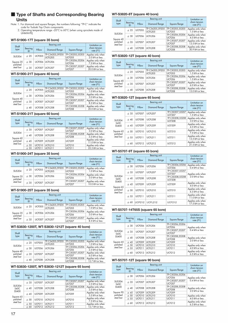
■ Type of Shafts and Corresponding Bearing Units
Note: 1. For diamond and square flanges, the numbers following “TP-C” indicate the code for Tsubaki Top Chain components.
2. Operating temperature range –20°C to 60°C (when using sprockets made of UHMW-PE)
WT-S1900-17T (square 35 bore)
Shafttype
Bearing unit Limitation onchain tension
rate (F1)Bearing
ID Pillow Diamond flange Square flange
SUS304
Square 35polishedsteel bar
φ 25 UCP205 TP-C54205,59205 TP-C50205,55205 Applies only when 2.0 kN or lessUCFL205 UCF205
φ 30 UCP206 UCFL206TP-C50206,55206 Applies only when
7.5 kN or lessUCF206
φ 35 UCP207 UCFL207TP-C50207,55207 Applies only when
20.0 kN or lessUCF207
17
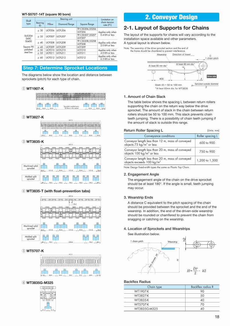
2-1. Layout of Supports for ChainsThe layout of the supports for chains will vary according to the installation space available and other parameters. A typical layout is shown below.
1. Amount of Chain Slack
The table below shows the spacing L between return rollers supporting the chain on the return way below the drive sprocket. The amount of slack in the chain between return rollers should be 50 to 100 mm. This slack prevents chain teeth jumping. There is a possibility of chain teeth jumping if the amount of slack is outside this range.
Return Roller Spacing L
2. Engagement Angle
The engagement angle of the chain on the drive sprocket should be at least 180°. If the angle is small, teeth jumping may occur.
3. Wearstrip Ends
A distance C equivalent to the pitch spacing of the chain should be provided between the sprocket and the end of the wearstrip. In addition, the end of the driven-side wearstrip should be rounded or chamfered to prevent the chain from snagging or catching on the wearstrip.
4. Location of Sprockets and Wearstrips
See illustration below.
Backflex RadiusChain type Backflex radius R
WT1907-K 90WT3827-K 50WT3835-K 40WT5707-K 70WT3835G-M325 40
(Units: mm)
Conveyance conditions Roller spacing L
Conveyor length less than 12 m, mass of conveyed objects 75 kg/m2 or less 600 to 900
Conveyor length less than 20 m, mass of conveyed objects 100 kg/m2 or less 750 to 900
Conveyor length less than 20 m, mass of conveyed objects exceeds 100 kg/m2 1,200 to 1,500
Note: Design fixed-width types the same as Plastic Top Chain.
2. Conveyor Design
②WT3827-K
①WT1907-K
The diagrams below show the location and distance between sprockets (pitch) for each type of chain.
Wearstrip1 chain pitch
H
Pitch
dia
mete
rDP
H= DP - h22
Wearstrip1 chain pitch
H
Pitch
dia
mete
rDP
H= DP - h22
h2
88.9 63.5 88.9 63.5 88.9 31.7531.75
457.2
41.3 41.3
③WT3835-K
⑤WT5707-K
④WT3835-T (with float-prevention tabs)
⑥WT3835G-M325
35.8 80.8 71.6 80.8 71.6 35.880.8
457.2
25.4 50.8 50.8Sprockets installed every 50.8mm in this section 25.450.8 50.8
38.1 76.2 76.2 76.276.2 76.2 38.1
457.2
25.4 101.6 25.450.8 101.6 50.8 101.6
38.1 76.2 228.6 38.176.2
457.2
25.4 101.6 101.6 25.4101.650.8 50.8
26.2
WT-S5707-14T (square 90 bore)
Shafttype
Bearing unit Limitation onchain tension
rate (F1)Bearing
ID Pillow Diamond flange Square flange
SUS304S45CSS400
Square 90polishedsteel bar
φ 30 UCP206 UCFL206TP-C50206,55206
Applies only when 0.4 kN or less
UCF206
φ 35 UCP207 UCFL207TP-C50207,55207UCF207
φ 40 UCP208 UCFL208TP-C50208,55208
Applies only when 2.0 kN or lessUCF208
φ 45 UCP209 UCFL209 UCF209φ 50 UCP210 UCFL210 UCF210 Applies only when
4.0 kN or lessφ 55 UCP211 UCFL211 UCF211
φ 60 UCP212 UCFL212 UCF212 Applies only when 6.5 kN or less
Machined solid sprocket
Machined solid sprocket
Molded split sprocket
Molded split sprocket
Step 7: Determine Sprocket Locations
Note: The wearstrip of the drive sprocket section and the end of the frame should be chamfered to prevent interference.
チェーン1ピッチ
Wearstrip Direction of travel
1 chain pitchC
Slack (δ) = 50 to 100 mm
δ
RAt least 80 mm dia.*
AL
A=2
Sprocket outside diameter
At least 80 mm dia.*
400400Drive side
*At least 60mm dia. for WT3835
18
Single strand Multi-strand
45 45
1
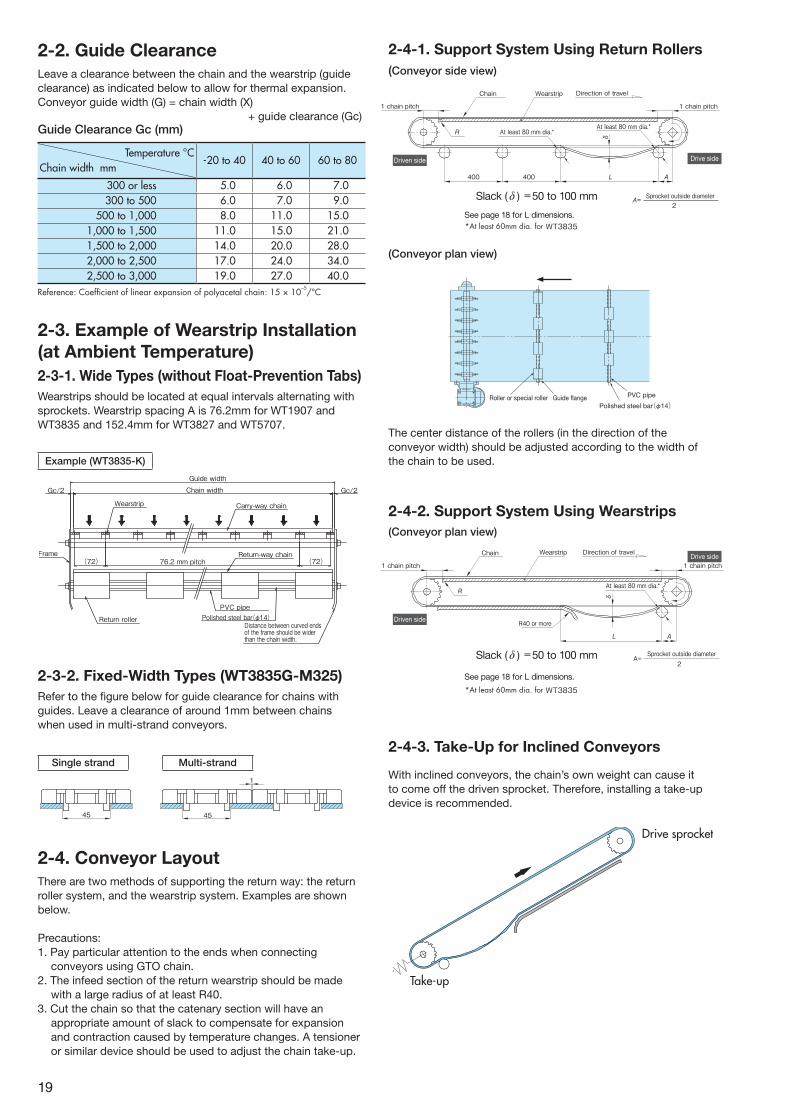
2-2. Guide ClearanceLeave a clearance between the chain and the wearstrip (guide clearance) as indicated below to allow for thermal expansion.Conveyor guide width (G) = chain width (X)
+ guide clearance (Gc)
2-3. Example of Wearstrip Installation (at Ambient Temperature)2-3-1. Wide Types (without Float-Prevention Tabs)Wearstrips should be located at equal intervals alternating with sprockets. Wearstrip spacing A is 76.2mm for WT1907 and WT3835 and 152.4mm for WT3827 and WT5707.
Temperature °CChain width mm
-20 to 40 40 to 60 60 to 80
300 or less 5.0 6.0 7.0300 to 500 6.0 7.0 9.0
500 to 1,000 8.0 11.0 15.01,000 to 1,500 11.0 15.0 21.01,500 to 2,000 14.0 20.0 28.02,000 to 2,500 17.0 24.0 34.02,500 to 3,000 19.0 27.0 40.0
Reference: Coefficient of linear expansion of polyacetal chain: 15 × 10–5/°C
Guide Clearance Gc (mm)
64A
Wearstrip
Guide width
Chain widthGc/2 Gc/2
Return-way chain
Gc/2 Gc/2
76.2 mm pitchFrame
Return roller
PVC pipePolished steel bar(φ14)
Distance between curved ends of the frame should be wider than the chain width.
Gc/2 Gc/2
82
Carry-way chain
(72) (72)
Wearstrip
Guide width
Chain width
Return-way chain76.2 mm pitch
Frame
Return roller
PVC pipePolished steel bar(φ14)
Distance between curved ends of the frame should be wider than the chain width.
Carry-way chain
(72)
レール(全面受け)
ガイド幅
チェーン幅
帰り側チェーンフレーム
特ローラ塩ビ等のパイプ
ミガキ棒鋼フレーム曲げ部先端はチェーン幅の内側に入らないようにします。
搬送用チェーン
2-3-2. Fixed-Width Types (WT3835G-M325)Refer to the figure below for guide clearance for chains with guides. Leave a clearance of around 1mm between chains when used in multi-strand conveyors.
2-4-1. Support System Using Return Rollers(Conveyor side view)
(Conveyor plan view)
The center distance of the rollers (in the direction of the conveyor width) should be adjusted according to the width of the chain to be used.
2-4-2. Support System Using Wearstrips(Conveyor plan view)
Polished steel bar(φ14)Guide �angeRoller or special roller PVC pipe
1 chain pitch
Chain Wearstrip Direction of travel
1 chain pitch
Slack (δ) = 50 to 100 mm
δ
RAt least 80 mm dia.*
AL
A=2
Sprocket outside diameter
At least 80 mm dia.*
400400
1 chain pitch
Chain Wearstrip Direction of travel
1 chain pitch
δ
R
R40 or more
At least 80 mm dia.*
AL
A=2
Sprocket outside diameter
Driven side
Driven side
Drive side
Drive side
Slack (δ) =50 to 100 mm
Slack (δ) =50 to 100 mm
See page 18 for L dimensions.
See page 18 for L dimensions.
2-4. Conveyor LayoutThere are two methods of supporting the return way: the return roller system, and the wearstrip system. Examples are shown below.
Precautions:1. Pay particular attention to the ends when connecting
conveyors using GTO chain. 2. The infeed section of the return wearstrip should be made
with a large radius of at least R40.3. Cut the chain so that the catenary section will have an
appropriate amount of slack to compensate for expansion and contraction caused by temperature changes. A tensioner or similar device should be used to adjust the chain take-up.
Drive sprocket
Take-up
*At least 60mm dia. for WT3835
*At least 60mm dia. for WT3835
2-4-3. Take-Up for Inclined Conveyors
With inclined conveyors, the chain’s own weight can cause it to come off the driven sprocket. Therefore, installing a take-up device is recommended.
Example (WT3835-K)
19
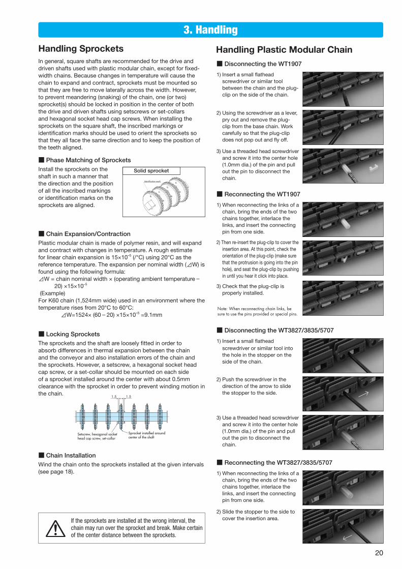
■ Disconnecting the WT1907
1) Insert a small flathead screwdriver or similar tool between the chain and the plug-clip on the side of the chain.
1) Insert a small flathead screwdriver or similar tool into the hole in the stopper on the side of the chain.
1) When reconnecting the links of a chain, bring the ends of the two chains together, interlace the links, and insert the connecting pin from one side.
1) When reconnecting the links of a chain, bring the ends of the two chains together, interlace the links, and insert the connecting pin from one side.
2) Using the screwdriver as a lever, pry out and remove the plug-clip from the base chain. Work carefully so that the plug-clip does not pop out and fly off.
2) Push the screwdriver in the direction of the arrow to slide the stopper to the side.
2) Slide the stopper to the side to cover the insertion area.
2) Then re-insert the plug-clip to cover the insertion area. At this point, check the orientation of the plug-clip (make sure that the protrusion is going into the pin hole), and seat the plug-clip by pushing in until you hear it click into place.
3) Use a threaded head screwdriver and screw it into the center hole (1.0mm dia.) of the pin and pull out the pin to disconnect the chain.
3) Use a threaded head screwdriver and screw it into the center hole (1.0mm dia.) of the pin and pull out the pin to disconnect the chain.
3) Check that the plug-clip is properly installed.
■ Reconnecting the WT1907
Note: When reconnecting chain links, be sure to use the pins provided or special pins.
■ Disconnecting the WT3827/3835/5707
■ Reconnecting the WT3827/3835/5707
3. Handling
■ Chain Expansion/ContractionPlastic modular chain is made of polymer resin, and will expand and contract with changes in temperature. A rough estimate for linear chain expansion is 15×10–5 (/°C) using 20°C as the reference temperature. The expansion per nominal width (⊿W) is found using the following formula:⊿W = chain nominal width × (operating ambient temperature-
20) ×15×10–5
(Example) For K60 chain (1,524mm wide) used in an environment where the temperature rises from 20°C to 60°C: ⊿W=1524× (60-20) ×15×10–5 =9.1mm
In general, square shafts are recommended for the drive and driven shafts used with plastic modular chain, except for fixed-width chains. Because changes in temperature will cause the chain to expand and contract, sprockets must be mounted so that they are free to move laterally across the width. However, to prevent meandering (snaking) of the chain, one (or two) sprocket(s) should be locked in position in the center of both the drive and driven shafts using setscrews or set-collars and hexagonal socket head cap screws. When installing the sprockets on the square shaft, the inscribed markings or identification marks should be used to orient the sprockets so that they all face the same direction and to keep the position of the teeth aligned.
■ Locking SprocketsThe sprockets and the shaft are loosely fitted in order to absorb differences in thermal expansion between the chain and the conveyor and also installation errors of the chain and the sprockets. However, a setscrew, a hexagonal socket head cap screw, or a set-collar should be mounted on each side of a sprocket installed around the center with about 0.5mm clearance with the sprocket in order to prevent winding motion in the chain.
■ Chain InstallationWind the chain onto the sprockets installed at the given intervals (see page 18).
Setscrew, hexagonal socket head cap screw, set-collar
Sprocket installed around center of the shaft
1.5 1.5
Handling Plastic Modular ChainHandling Sprockets
■ Phase Matching of SprocketsInstall the sprockets on the shaft in such a manner that the direction and the position of all the inscribed markings or identification marks on the sprockets are aligned.
Identification mark
If the sprockets are installed at the wrong interval, the chain may run over the sprocket and break. Make certain of the center distance between the sprockets.
Solid sprocket
20
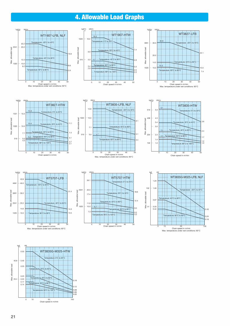
4. Allowable Load Graphs
0 10 50
kN/m
15.9
8.8
5.9
Temperature: –20°C to 40°C
Temperature: 40°C to 60°C
Temperature: 60°C to 80°C
20 30 40
20.0
10.0
22.2
12.3
8.2
Chain speed in m/minMax. temperature under wet conditions: 60°C
Max
. allo
wab
le lo
ad
WT1907-LFB, NLF
2041
1020
kgf/m
0 10 50
kN/m
7.4
2.52.0
Temperature: 5°C to 20°C
Temperature: 20°C to 40°C
Temperature: 40°C to 60°C
20 30 40
10.0
5.0
Temperature: 60°C to 80°C
Temperature: 80°C to 105°C
4.9
3.3
10.3
3.42.9
6.9
4.7
Chain speed in m/min
WT1907-HTW1020
510
kgf/m
Max
. allo
wab
le lo
ad
0 10 50
kN/m
Temperature: –20°C to 40°C
Temperature: 40°C to 60°C
Temperature: 60°C to 80°C
20 30 40
30.0
10.0
20.022.1
10.0
7.4
30.9
14.0
10.3
WT3827-LFB
1020
3061
kgf/m
Chain speed in m/minMax. temperature under wet conditions: 60°C
Max
. allo
wab
le lo
ad
WT3827-HTW
0 10 50
kN/m
11.1
3.73.1
Temperature: 5°C to 20°C
Temperature: 20°C to 40°C
Temperature: 40°C to 60°C
20 30 40
10.0
5.0Temperature: 60°C to 80°C
Temperature: 80°C to 105°C
7.4
5.1
15.6
5.2
4.3
10.4
7.1
15.0
kgf/m
1531
1020
510
Chain speed in m/min
Max
. allo
wab
le lo
ad
0 10 50
kN/m
9.1
5.1
3.4
Temperature: –20°C to 40°C
Temperature: 40°C to 60°C
Temperature: 60°C to 80°C
20 30 40
10.0
5.0
12.8
7.1
4.7
WT3835-LFB, NLF
1020
510
kgf/m
Chain speed in m/minMax. temperature under wet conditions: 60°C
Max
. allo
wab
le lo
ad
0 10 50
kN/m
3.6
1.21.0
Temperature: 5°C to 20°C
Temperature: 20°C to 40°C
Temperature: 40°C to 60°C
20 30 40
5.0
Temperature: 60°C to 80°C
Temperature: 80°C to 105°C
2.4
1.7
5.1
1.7
1.4
3.4
2.3
4.0
3.0
2.0
1.0
WT3835-HTW
kgf/m
Chain speed in m/min
102
204
408
510
Max
. allo
wab
le lo
ad
WT5707-LFB
0 10 50
kN/m
Temperature: –20°C to 40°C
Temperature: 40°C to 60°C
Temperature: 60°C to 80°C
20 30 40
40.0
20.0
30.031.4
14.3
10.5
43.9
14.6
10.0
2041
1020
3061
4081
kgf/m
Chain speed in m/minMax. temperature under wet conditions: 60°C
Max
. allo
wab
le lo
ad
0 10 50
kN/m
18.6
6.25.2
Temperature: 5°C to 20°C
Temperature: 20°C to 40°C
Temperature: 40°C to 60°C
20 30 40
10.0
Temperature: 60°C to 80°C
Temperature: 80°C to 105°C
12.4
8.5
26.1
8.7
7.3
17.4
11.9
20.0
WT5707-HTW
2041
1020
kgf/m
Chain speed in m/min
Max
. allo
wab
le lo
ad
0 100
kN
0.43
0.24
0.16
Temperature: –20°C to 40°C
Temperature: 40°C to 60°C
Temperature: 60°C to 80°C
50
1.00
0.50
1.20
0.67
0.44
15
kgf
WT3835G-M325-LFB, NLF
Chain speed in m/minMax. temperature under wet conditions: 60°C
102
51Max
. allo
wab
le lo
ad
WT3835G-M325-HTW
kN
0.18
0.060.05
Temperature: 5°C to 20°C
Temperature: 20°C to 40°C
Temperature: 40°C to 60°C
0.50
Temperature: 60°C to 80°C
Temperature: 80°C to 105°C
0.12
0.08
0.170.14
0.33
0.23
0.40
0.20
0 1005015Chain speed in m/min
kgf
40.8
20.4Max
. allo
wab
le lo
ad
21
General• Do not use chain or chain accessories for any purpose other than their originally intended use.• Never perform additional work on chain (including machining, grinding, annealing, cleaning with acids or alkalis, electroplating, or welding or cutting with
a torch which will cause heat effects). These processes may cause the chain to break during operation, leading to a risk of severe injury. • When replacing a worn or damaged part, do not replace just the worn or damaged part. Replace all parts with new parts. The chain may break during
operation, leading to a risk of severe injury.• When using chain in a lifting device, set up a safety barrier and do not allow anyone to go under the equipment. Also, when jigs or tools are connected to
the edges of the chain, be sure to adequately lubricate the connecting parts. Detachment of the chain or unexpected chain breakage may lead to severe injury from flying or falling parts.
• Strictly observe the general guidelines listed in Section 1, Chapter 1, 2nd Edition of the Japanese Occupational Safety and Health Regulations as well as rules and regulations concerning occupational safety and health in your region/country. Always install safety equipment (safety covers, etc.) on chain and sprockets. There is a risk of severe injury from conveyed items or the chain as a result of becoming caught in the chain or from unexpected chain breakage.
• Chain and sprockets must be inspected on a regular basis. Damaged parts, or parts that have reached the end of their service life, should be replaced with new parts. There is a risk not only of the chain not functioning properly, but also of severe injury from chain breakage or abnormal operation. Perform the work as instructed in the manual, catalog or other documentation that was provided with the product.
During Installation• Before starting work, turn off the power switch and take measures to prevent it from being turned on accidentally. There is a risk of severe injury from
becoming caught in the chain.• Always wear safety goggles when using hammers while working to connect chains. There is a risk of severe injury from flying metal fragments or splinters. • Secure the chain and parts to prevent them from moving freely. There is a risk of severe injury from chain components moving under their own weight, or
from falling and body parts becoming pinched in the chain.
• Understand the structure and specifications of the chain that you are handling.• Before installing chain, inspect it to make sure no damage occurred during delivery.• Inspect and maintain chain and sprockets at regular intervals.• Chain strength varies by manufacturer. Only Tsubaki products should be used when chain is selected using Tsubaki catalogs.• Start and stop the chain gradually, and do not subject it to sudden impact.• Do not apply initial tension to the chain.• Consult a Tsubaki representative before using the chain in cases where it will be in contact with special liquids or used under special environments.• When disconnecting chains that have engineering plastic pins, do not reuse a pin once removed since it may not engage properly or it may even come loose. • When using chains with engineering plastic pins under wet conditions, make sure that the temperature does not exceed 60°C.• The link material for ULF ultra low friction series contains silicone-based lubricant. Therefore, do not use this chain for printing processes, or in cases where
silicone will have a harmful effect.• The TP-IR18/IR60/RR55 (return rollers), PR520-M (M plastic rail), and SJ-CNO are dry conveyor parts (lube-free, no water adhesion). DIA, MPD, MF, HS, and
KV150 chains are specifically for dry environments. Do not use these on a conveyor under wet conditions (environments where they will come into contact with water, soapy water or other liquids), since this may cause the chain to malfunction. Bearing corner discs are also designed for use in dry environments.
• Using a plastic top chain in a wet environment will decrease the resin’s self-lubricating ability and thus shorten the life of the chain. Since this is especially true with stainless steel pins, we recommend using plastic pins or KV series chain.
• The operating temperature range for accessories, sprockets, and idler wheels made of UHMW-PE (ultra-high molecular weight polyethylene) is –20°C to 60°C. Also, do not use in environments where such components will be exposed to steam.
• Toxic gases may be generated if the Chemical Resistant series (including Super Chemical Resistant) is exposed directly to open flame, or to temperatures above 150°C. Do not expose to excessive heat or to open flame.
• Plastic chain is flammable. Do not use at temperatures above the maximum allowable temperature or use near open flame. Combustion may generate dangerous toxic gases.
1. LIMITED WARRANTYProducts manufactured by Seller: (a) conform to the design and specifications, if any, expressly agreed to in writing by Seller; and (b) are free of defects in workmanship and materials at the time of shipment. The warranties set forth in the preceding sentence are exclusive of all other warranties, express or implied, and extend only to Buyer and to no other person. ALL WARRANTIES OF MERCHANTABILITY OR FITNESS FOR A PARTICULAR PURPOSE ARE HEREBY EXCLUDED.
2. NON-RELIANCEBuyer is not relying upon any advice, representations or warranties (except the warranties expressly set forth above) of Seller, or upon Seller’s skill or judgment regarding the Seller’s products. Buyer is solely responsible for the design and specifications of the products, including without limitation, the determination of suitability for Buyer’s application of the products.
3. CLAIMS(a) Any claim relating to quantity or type shall be made to Seller in
writing within 7 days after receipt of the products; any such claim made thereafter shall be barred.
(b) Any claim under the above-stated Limited Warranty shall be made to Seller in writing within three (3) months after receipt of the products; any such claim made thereafter shall be barred.
(c) Seller’s liability for breach of warranty or otherwise is limited to repair or replacement, at Seller’s option, of non-conforming or defective products. Buyer waives all other remedies, including, but not limited to, all rights to consequential, special or incidental
damages, including, but not limited to, damages resulting from personal injury, death or damage to or loss of use of property.
(d) Repair, alteration, neglect or misuse of the products shall void all applicable warranties.
4. INDEMNIFICATIONBuyer will indemnify, defend and hold Seller harmless from all loss, liability, damage and expense, including attorneys’ fees, arising out of any claim (a) for infringement of any patent, trademark, copyright, misappropriation of trade secrets, unfair competition or similar charge by any products supplied by Seller in accordance with the design or specifications furnished by Buyer, or (b) arising out of or connected with the products or any items into which the products are incorporated, including, but not limited to, any claim for product liability (whether or not based on negligence or strict liability of Seller), breach of warranty, breach of contract or otherwise.
5. ENTIRE AGREEMENTThese terms and conditions constitute the entire agreement between Buyer and Seller and supersede any inconsistent terms and conditions, whether contained in Buyer’s purchase order or otherwise, and whether made heretofore or hereafter. No statement or writing subsequent to the date hereof which purports to modify or add to the terms and conditions hereof shall be binding unless consented to in writing, which makes specific reference hereto, and which has been signed by the party against which enforcement thereof is sought. Seller reserves the right to change these terms and conditions without prior notice.
For Your Safety When Using the ChainWarning
Caution
Warranty
To avoid danger, observe the following rules.
To prevent accidents, observe the following rules.
22
HeadquartersNakanoshima Mitsui Building 3-3-3 Nakanoshima, Kita-ku Osaka 530-0005, JapanPhone : +81-6-6441-0011Facsimile : +81-6-6441-0489Internet:http://tsubakimoto.com/
Top Chain Products Department2-15-16 Takanawa, Minato-kuTokyo 108-0074, JapanPhone : +81-3-3445-8512Facsimile : +81-3-3445-8636Internet:http://tsubaki-yamakyu.co.jp/
Global Market Development Department2-15-16 Takanawa, Minato-kuTokyo 108-0074, JapanPhone : +81-3-3445-8518Facsimile : +81-3-3445-4330
TSUBAKI YAMAKYU CHAIN CO.
Catalog No. ME13Y2 ©2013/7 TSUBAKIMOTO CHAIN CO. Printed in Japan 1,000
U.S. TSUBAKI POWER TRANSMISSION, LLC301 E. Marquardt Drive, Wheeling, IL 60090-6497, U.S.A. Phone : +1-847-459-9500 Facsimile : +1-847-459-9515
TSUBAKI of CANADA LIMITED 1630 Drew Road, Mississauga, Ontario L5S 1J6, Canada Phone : +1-905-676-0400 Facsimile : +1-905-676-0904
TSUBAKI BRASIL EQUIPAMENTOS INDUSTRIAIS LTDA. Rua Pamplona, 1018 - CJ. 73/74, Jardim Paulista CEP 01405-001, São Paulo – S.P. Brazil Phone : +55-11-3253-5656 Facsimile : +55-11-3253-3384
TSUBAKI INDIA POWER TRANSMISSION PTE. LTD.Chandrika Chambers No.4, 3rd Floor, Anthony Street, Royapettah, Chennai-600014, Tamil Nadu, India Phone : +91-44-4231-5251 Facsimile : +91-44-4231-5253
TSUBAKI AUSTRALIA PTY. LTD. Unit E, 95-101 Silverwater Road Silverwater, N.S.W. 2128, Australia Phone : +61-2-9704-2500 Facsimile : +61-2-9704-2550
TSUBAKI AUSTRALIA PTY LIMITED NEW ZEALAND BRANCH 2 Kalmia Street, Ellerslie, Auckland 1051, New Zealand Phone : +64-275-082-726 Facsimile :
PT. TSUBAKI INDONESIA TRADINGWisma 46 - Kota BNI, 24th Floor, Suite 24.15 Jl. Jend. Sudirman, Kav. 1 Jakarta 10220, Indonesia Phone : +62-21-571-4230/1 Facsimile : +62-21-571-4232
TSUBAKI POWER TRANSMISSION (MALAYSIA) SDN. BHD.No. 22, Jalan Astaka U8/84A, Bukit Jelutong Industrial Park,Section U8, 40150 Shah Alam, Selangor, Malaysia Phone : +60-3-7859-8585 Facsimile : +60-3-7859-7575
TAIWAN TSUBAKIMOTO CO. No. 33, Lane 17, Zihciang North Road Gueishan Township, Taoyuan County, Taiwan Phone : +886-33-293827/8/9 Facsimile : +886-33-293065
TSUBAKIMOTO CHAIN TRADING (SHANGHAI) CO., LTD. Room 601, Urban City Centre, 45 Nanchang Road Huangpu District, Shanghai 200020, People’s Republic of China Phone : +86-21-5396-6651/2 Facsimile : +86-21-5396-6628
TSUBAKIMOTO CHAIN CO. KOREA OFFICE#1401, West Wing, Hanshin Intervalley 24, 707-34 Yeoksam 2(i)-dong, Gangnamu-gu, Seoul, Korea Phone : +82-2-2183-0311 Facsimile : +82-2-2183-0314
Global Associated Partners:
TSUBAKIMOTO SINGAPORE PTE. LTD. 25 Gul Lane, Jurong, Singapore 629419 Phone : +65-6861-0422/3/4 Facsimile : +65-6861-7035
TSUBAKIMOTO SINGAPORE PTE. LTD. VIETNAM REPRESENTATIVE OFFICE8F H&H Building, 209 Hoang Van Thu Phu Nhuan District, Ho Chi Minh City, Vietnam Phone : +84-8-3999-0131 or 0132 Facsimile : +84-8-3999-0130
TSUBAKIMOTO (THAILAND) CO., LTD.388 Exchange Tower, 19th Floor, Unit 1902 Sukhumvit Road, Klongtoey, Bangkok 10110, Thailand Phone : +66-2-262-0667 Facsimile : +66-2-262-0670
ASIA and OCEANIA
TSUBAKIMOTO EUROPE B.V. Aventurijn 1200, 3316 LB Dordrecht, The Netherlands Phone : +31-78-6204000 Facsimile : +31-78-6204001
TSUBAKI KABELSCHLEPP (RUSSIA)Prospekt Andropova 18 Building 6 115432 Moscow, Russia Phone : +7-499-4180212Facsimile : +7-499-4180212
TSUBAKIMOTO U.K. LTD. Osier Drive, Sherwood Park, Annesley, Nottingham NG15 0DX U.K. Phone : +44-1623-688-700 Facsimile : +44-1623-688-789
TSUBAKI DEUTSCHLAND GmbH ASTO Park Oberpfaffenhofen, Friedrichshafener Straße 1 D-82205 Gilching, Germany Phone : +49-8105-7307100 Facsimile : +49-8105-7307101
EUROPE
NORTH and SOUTH AMERICA
Note: In accordance with the policy of TSUBAKIMOTO CHAIN CO. to constantly improve its products, the speci�cations in this catalog are subject to change without notice.The logos, brand names, or product names in this catalog are trademarks or registered trademarks of Tsubakimoto Chain Co. in Japan and other countries.
2013年6月1日発行 Ⓒ株式会社 椿本チエイン Bulletin No.13001


