8
NEW TSUBAKI Plastic Top Chain TTUPS-H

NEW
TSUBAKIPlastic Top ChainTTUPS-H
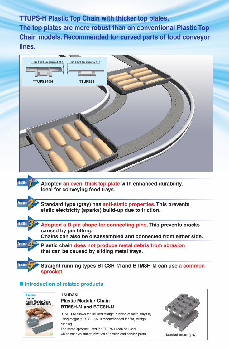
Adopted an even, thick top plate with enhanced durability. Ideal for conveying food trays.
Standard type (gray) has anti-static properties. This prevents static electricity (sparks) build-up due to friction.
Adopted a D-pin shape for connecting pins. This prevents cracks caused by pin fi tting.Chains can also be disassembled and connected from either side.
Plastic chain does not produce metal debris from abrasionthat can be caused by sliding metal trays.
Straight running types BTC8H-M and BTM8H-M can use a common sprocket.
Standard product (gray)
■ Introduction of related products
Tsubaki
Plastic Modular Chain
BTM8H-M and BTC8H-M
BTM8H-M allows for inclined straight running of metal trays by
using magnets. BTC8H-M is recommended for fl at, straight
running.
The same sprocket used for TTUPS-H can be used,
which enables standardization of design and service parts.
TTUPS-H Plastic Top Chain with thicker top plates.
The top plates are more robust than on conventional Plastic Top
Chain models. Recommended for curved parts of food conveyor
lines.
TSUBAKIPlastic Modular ChainBTM8H-M and BTC8H-M
PAT.P
Feature
Feature
Feature
Feature
Feature5
4
3
2
1
Thickness of top plate: 9.8 mm Thickness of top plate: 4.0 mm
TTUP826TTUPS840H

■ Chain (Stainless Steel Pins)
Tsubaki model no.
MarterialMaterial
markLink color
Anti-static effectMax. allowable load
kN{kgf}Approx. mass
kg/m
Operating temperature range
˚C
Max. allowable speed m/min TTUPS-H
With lube No lube
TTUPS840H-GStandard
G Gray Anti-static1.08 {110} 1.8 -20 to 80 100 50
�
TTUPS840H - Blue - �
Note: 1. �: Standard product �: Made-to-order productFor further specifi cation requirements, please contact a Tsubaki representative.
2. Plastic pins are not available.
3. Standard chain length is 120 links.
● Top plate with a thickness of 9.8 mm makes for a more chip-proof chain compared to conventional models.
● D-pin shape has been adopted for the connecting pins, which prevents the occurrence of cracks from the fi tting of pins into the pin holes and enables pin insertion from either side during maintenance.
■ Model Numbering
Note: Do not leave spaces between letters and symbols.
■ Connecting Pin
304 stainless steel D-pin
Model no. TTUP-SUS-JPD
Standard grade polyacetal resin with excellent
mechanical properties is used.
This type has anti-static properties that prevent
the adhesion of dust and wear debris as well as
sparks from static electricity. (Available only in
gray)
G: Standard type (gray)
B: Standard type (blue)
Chain type Chain materialChain typePlate width
Specifi cations (Plastic chain material)
Standard type
General-purpose polyacetal chain links
Plastic Top Chain TTUPS-H
1. Standard type (gray, blue)
2. Anti-static type (gray only)
Direction of travel
Min. back-flex radius = 170 mm
Min. sideflex radius = R450 Wearstrip
Color: Gray (standard product)
Color: Blue (Made-to-order product)
<Sidefl exing>
Features
* Magnets can also be integrated into the chain link. Please contact a Tsubaki representative for further information.

Tsubaki model no. TeethPitch
diameterDP
Outside diameter
DO
Bore shape
Bore diameter
d
Keyway Hub diameter
DH
Approx.mass
kgType
MaterialWT-SW2500
W H Body Bolts and nuts
WT-SW2500-16T25
16 130.2 131.9
Round
25 8 28.3
82
0.26
Split
Reinforced
polyamide
(Black)
Stainless steel
�
WT-SW2500-16T30 30 8 33.3 0.25 �
WT-SW2500-16T35 35 10 38.3 0.24 �
WT-SW2500-16T40 40 12 43.3 0.24 �
WT-SW2500-18T25
18 146.3 148.3
25 8 28.3 0.30 �
WT-SW2500-18T30 30 8 33.3 0.29 �
WT-SW2500-18T35 35 10 38.3 0.28 �
WT-SW2500-18T40 40 12 43.3 0.28 �
WT-SW2500-21T25
21 170.4 172.7
25 8 28.3 0.36 �
WT-SW2500-21T30 30 8 33.3 0.35 �
WT-SW2500-21T35 35 10 38.3 0.34 �
WT-SW2500-21T40 40 12 43.3 0.33 �
Note: 1. �: Standard product �: Made-to-order product
2. Bolt tightening torque: 5.7 N.m
3. When assembling the sprockets, do not mix the pairs.
4. Operating temperature range: -20°C to 80°C.
5. Machined solid sprockets (steel or engineering plastic) can also be fabricated upon request. Contact a Tsubaki representative for further information.
Tsubaki model no.Equivalent no.
of teethOutside diameter
DO
Shaft diameterd
Hub lengthL
WidthT
Approx.masskg
Material Type
TP-C12077BT-IW
15 129.8
25
61 58
0.26
Bolt & nut:
Stainless steel
Body:
Polyamide
(color: black)
Split
TP-C12078BT-IW 30 0.25
TP-C12079BT-IW 35 0.28
TP-C12080BT-IW 40 0.25
TP-C121928BT-IW
16.5 142.2
25
61 58
0.29
TP-C121929BT-IW 30 0.27
TP-C121930BT-IW 35 0.30
TP-C121931BT-IW 40 0.27
TP-C12081BT-IW
18 154.7
25
61 58
0.32
TP-C12082BT-IW 30 0.30
TP-C12083BT-IW 35 0.32
TP-C12084BT-IW 40 0.30
Note: 1. Standard product.
2. Operating temperature range: -20°C to 80°C.
3. Bolt tightening torque: 6 N.m {0.61 kgf.m}
4. When assembling the halves of the idler wheel, do not mix the halves with halves from other idler wheels.
5. Should not be used under abrasive conditions.
6. Shaft metal must be polished.
7. Solid type idler wheels are also available. Contact a Tsubaki representative for further information.
No. Tsubaki model no.Centerradius (mm)
Side Material Color Angle
① PR-TTUPSH-R600WIN30600
Inside Ultra high molecular weight polyethylene
White 30°② PR-TTUPSH-R600WOUT30 Outside
① PR-TTUPSH-R600GIN30600
Inside Ultra high molecular weight polyethylene
Green 30°② PR-TTUPSH-R600GOUT30 Outside
CCC tt
Split sprocket
WT-SW2500-16T WT-SW2500-18T WT-SW2500-21T
Corner rails
Idler wheel
Note: Made-to-order product
■ Model Numbering
Plastic rail
Chain type Color Side
W: White IN: Inside
G: Green OUT: Outside
AngleChain side-flex
radius
Note: Do not leave spaces between letters and symbols.
Base plate(prepared by customer)
A-A cross-section
8.5 mm (for M8)
φd
44
φDo
LT
Split type
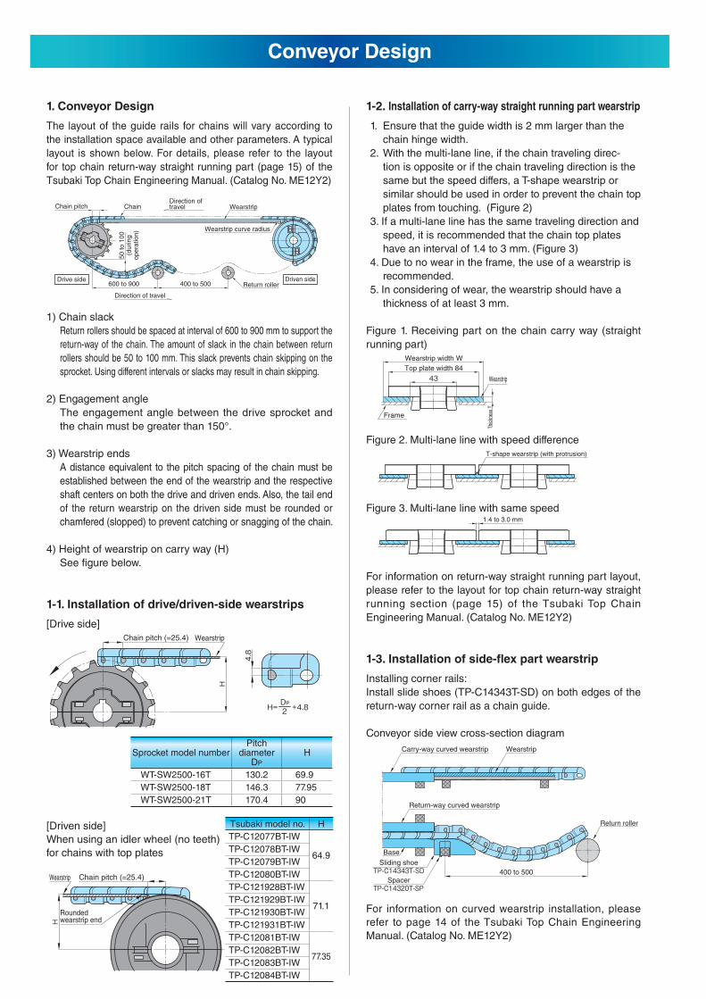
1. Conveyor Design
The layout of the guide rails for chains will vary according to
the installation space available and other parameters. A typical
layout is shown below. For details, please refer to the layout
for top chain return-way straight running part (page 15) of the
Tsubaki Top Chain Engineering Manual. (Catalog No. ME12Y2)
1) Chain slack
Return rollers should be spaced at interval of 600 to 900 mm to support the
return-way of the chain. The amount of slack in the chain between return
rollers should be 50 to 100 mm. This slack prevents chain skipping on the
sprocket. Using different intervals or slacks may result in chain skipping.
2) Engagement angle
The engagement angle between the drive sprocket and
the chain must be greater than 150°.
3) Wearstrip ends
A distance equivalent to the pitch spacing of the chain must be
established between the end of the wearstrip and the respective
shaft centers on both the drive and driven ends. Also, the tail end
of the return wearstrip on the driven side must be rounded or
chamfered (slopped) to prevent catching or snagging of the chain.
4) Height of wearstrip on carry way (H)
See fi gure below.
1-1. Installation of drive/driven-side wearstrips
[Drive side]
[Driven side]
When using an idler wheel (no teeth)
for chains with top plates
1-2. Installation of carry-way straight running part wearstrip
1. Ensure that the guide width is 2 mm larger than the
chain hinge width.
2. With the multi-lane line, if the chain traveling direc-
tion is opposite or if the chain traveling direction is the
same but the speed differs, a T-shape wearstrip or
similar should be used in order to prevent the chain top
plates from touching. (Figure 2)
3. If a multi-lane line has the same traveling direction and
speed, it is recommended that the chain top plates
have an interval of 1.4 to 3 mm. (Figure 3)
4. Due to no wear in the frame, the use of a wearstrip is
recommended.
5. In considering of wear, the wearstrip should have a
thickness of at least 3 mm.
Figure 1. Receiving part on the chain carry way (straight
running part)
Figure 2. Multi-lane line with speed difference
Figure 3. Multi-lane line with same speed
For information on return-way straight running part layout,
please refer to the layout for top chain return-way straight
running section (page 15) of the Tsubaki Top Chain
Engineering Manual. (Catalog No. ME12Y2)
1-3. Installation of side-fl ex part wearstrip
Installing corner rails:
Install slide shoes (TP-C14343T-SD) on both edges of the
return-way corner rail as a chain guide.
Conveyor side view cross-section diagram
For information on curved wearstrip installation, please
refer to page 14 of the Tsubaki Top Chain Engineering
Manual. (Catalog No. ME12Y2)
Conveyor Design
Sprocket model numberPitch
diameterDP
H
WT-SW2500-16T 130.2 69.9
WT-SW2500-18T 146.3 77.95
WT-SW2500-21T 170.4 90
Tsubaki model no. H
TP-C12077BT-IW
64.9TP-C12078BT-IW
TP-C12079BT-IW
TP-C12080BT-IW
TP-C121928BT-IW
71.1TP-C121929BT-IW
TP-C121930BT-IW
TP-C121931BT-IW
TP-C12081BT-IW
77.35TP-C12082BT-IW
TP-C12083BT-IW
TP-C12084BT-IW
Chain pitch (=25.4) Wearstrip
Chain pitch (=25.4)
Rounded wearstrip end
Wearstrip
Wearstrip width W
Frame
Thi
ckne
ss T
Wearstrip
Top plate width 84
1.4 to 3.0 mm
T-shape wearstrip (with protrusion)
Carry-way curved wearstrip
Return-way curved wearstrip
Sliding shoe
Spacer400 to 500
Base
Wearstrip
Return roller
Direction of travel
Direction of travel
Chain pitch
Drive side
50 to 1
00
(during
opera
tion)
Chain Wearstrip
Wearstrip curve radius
Return rollerDriven side
600 to 900 400 to 500
Item Method of Inspection Criteria for Judgment(*)
Chain elonga-tion due to
wear
Measure the length of 10 top plates by means of a measure with the chain slightly stretched to eliminate backlash through the chain links.
GradePercentage of chain
elongation
A 0 ≦ x < +1.2%
B +1.2% ≦ x < +2.6%
C +2.6% ≦ x
Percentage of elongation = (Measured length – Reference length)/Reference length × 100Reference length = chain pitch × 10Example:TTUPS-H chain: Result of measuring 10 links (reference length: 254mm)Percentage of elongation and judg-ment when measured length was 259mm:Percentage of elongation X = (259 – 254) / 254 × 100 ≈ 2.0.From table above, judgment is B.
Wear of top plate
Use a vernier caliper to measure the thickness of the part of the top plate that slides on the wear-strip. Also, verify that there are no bumps, depressions, or other irregularities measuring more than 1 mm in height or depth on the conveyor surface.
GradePlate thickness
9.8 mm
A 8.3-9.8 mm
B 5.9-8.2 mm
C 5.8 mm or thinner
Deformation of top plate
Inspect whether or not there is any place where the chain articu-lation is not proper due to corro-sion. If corrosion should worsen, remove rust and measure the thickness of the link plate by means of a vernier caliper.
Replace the part if deemed that it may affect operation. For scratches on the upper surface of the top plate due to abnormal contact, investigate the wearstrip on the return way to fi nd the causes and repair it as necessary.
Chain and wearstrip cross-section (side-fl ex part)
[Carry way]
[Return way]
3. Chain handling
3-1. Assembly and disassembly of chain
The D-pin type connecting pins allow for disassembly
from any part of the chain.
The pins can be inserted/removed from either side.
3-2. Chain Replacement Standards
A: Can be still used.
B: Still has margin of chain life but necessary to consider replacement.
C: Chain life is already exceeded, needs to be replaced.
(*)
For conveyor design information and information on the calculation of load and selection of accessories and chains that are not listed in this catalog, please refer to the Tsubaki Top Chain catalog and engineering manual.
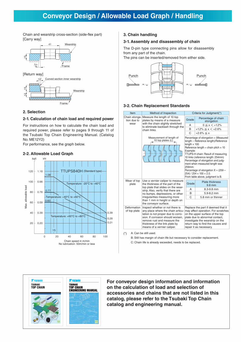
2. Selection
2-1. Calculation of chain load and required power
For instructions on how to calculate the chain load and
required power, please refer to pages 9 through 11 of
the Tsubaki Top Chain Engineering Manual. (Catalog
No. ME12Y2)
For performance, see the graph below.
2-2. Allowable Load Graph
Conveyor Design / Allowable Load Graph / Handling
Chain speed in m/minNo lubrication: 50m/min or less
(Standard type)
Ma
x.
allo
wa
ble
lo
ad
Temperature: -20°C to +40°C
Temperature: +60°C to +80°C
Temperature: +40°C to +60°C
Punch Punch
Wearstrip
Frame
Curved section inner wearstrip
Wearstrip
Frame
Measurement of length of10 top plates (L)
TSUBAKITOP CHAIN
TOP CH
AIN
TSUBAKITOP CHAINENGINEERING MANUAL
TSUBAKITOP CHAINENGINEERING MANUAL
General• Do not use chain or chain accessories for any purpose other than their originally intended use.• Never perform additional work on chain (including machining, grinding, annealing, cleaning with acids or alkalis, electroplating, or welding or cutting with a torch
which will cause heat effects). These processes may cause the chain to break during operation, leading to a risk of severe injury. • When replacing a worn or damaged part, do not replace just the worn or damaged part. Replace all parts with new parts. The chain may break during operation,
leading to a risk of severe injury.• When using chain in a lifting device, set up a safety barrier and do not allow anyone to go under the equipment. Also, when jigs or tools are connected to the edges
of the chain, be sure to adequately lubricate the connecting parts. Detachment of the chain or unexpected chain breakage may lead to severe injury from fl ying or falling parts.
• Strictly observe the general guidelines listed in Section 1, Chapter 1, 2nd Edition of the Japanese Occupational Safety and Health Regulations as well as rules and regulations concerning occupational safety and health in your region/country. Always install safety equipment (safety covers, etc.) on chain and sprockets. There is a risk of severe injury from conveyed items or the chain as a result of becoming caught in the chain or from unexpected chain breakage.
• Chain and sprockets must be inspected on a regular basis. Damaged parts, or parts that have reached the end of their service life, should be replaced with new parts. There is a risk not only of the chain not functioning properly, but also of severe injury from chain breakage or abnormal operation. Perform the work as instructed in the manual, catalog or other documentation that was provided with the product.
During Installation• Before starting work, turn off the power switch and take measures to prevent it from being turned on accidentally. There is a risk of severe injury from becoming
caught in the chain.• Always wear safety goggles when using hammers while working to connect chains. There is a risk of severe injury from fl ying metal fragments or splinters. • Secure the chain and parts to prevent them from moving freely. There is a risk of severe injury from chain components moving under their own weight, or from
falling and body parts becoming pinched in the chain.
• Understand the structure and specifi cations of the chain that you are handling.• Before installing chain, inspect it to make sure no damage occurred during delivery.• Inspect and maintain chain and sprockets at regular intervals.• Chain strength varies by manufacturer. Only Tsubaki products should be used when chain is selected using Tsubaki catalogs.• Start and stop the chain gradually, and do not subject it to sudden impact.• Do not apply initial tension to the chain.• Consult with a Tsubaki representative before using the chain in cases where it will be in contact with special liquids or used under special environments.• When disconnecting chains that have engineering plastic pins, do not reuse a pin once removed since it may not engage properly or it may even come loose. • When using chains with engineering plastic pins under wet conditions, make sure that the temperature does not exceed 60°C.• The link material for ULF ultra low friction series contains silicone-based lubricant. Therefore, do not use this chain for printing processes, or in cases where silicone
will have a harmful effect.• The TP-IR18/IR60/RR55 (return rollers), PR520-M (M plastic rail), and SJ-CNO are dry conveyor parts (lube-free, no water adhesion). DIA, MPD, MF, HS, and KV150
chains are specifi cally for dry environments. Do not use these on a conveyor under wet conditions (environments where they will come into contact with water,soapy water or other liquids), since this may cause the chain to malfunction. Bearing corner discs are also designed for use in dry environments.
• Using a plastic top chain in a wet environment will decrease the resin’s self-lubricating ability and thus shorten the life of the chain. Since this is especially truewith stainless steel pins, we recommend using plastic pins or KV series chain.
• The operating temperature range for accessories, sprockets, and idler wheels made of UHMW-PE (ultra-high molecular weight polyethylene) is –20°C to 60°C. Also, do not use in environments where such components will be exposed to steam.
• Toxic gases may be generated if the Chemical Resistant series (including Super Chemical Resistant) is exposed directly to open fl ame, or to temperatures above150°C. Do not expose to excessive heat or to open fl ame.
• Plastic chain is fl ammable. Do not use at temperatures above the maximum allowable temperature or use near open fl ame. Combustion may generate dangeroustoxic gases.
1. LIMITED WARRANTYProducts manufactured by Seller: (a) conform to the design and specifi cations, if any, expressly agreed to in writing by Seller; and (b) are free of defects in workmanship and materials at the time of shipment. The warranties set forth in the preceding sentence are exclusive of all other warranties, express or implied, and extend only to Buyer and to no other person. ALL WARRANTIES OF MERCHANTABILITY OR FITNESS FOR A PARTICULAR PURPOSE ARE HEREBY EXCLUDED.
2. NON-RELIANCEBuyer is not relying upon any advice, representations or warranties (except the warranties expressly set forth above) of Seller, or upon Seller’s skill or judgment regarding the Seller’s products. Buyer is solely responsible for the design and specifi cations of the products, including without limitation, the determination of suitability for Buyer’s application of the products.
3. CLAIMS(a) Any claim relating to quantity or type shall be made to Seller in writing
within 7 days after receipt of the products; any such claim made thereafter shall be barred.
(b) Any claim under the above-stated Limited Warranty shall be made to Seller in writing within three (3) months after receipt of the products; any such claim made thereafter shall be barred.
(c) Seller’s liability for breach of warranty or otherwise is limited to repair or replacement, at Seller’s option, of non-conforming or defective products. Buyer waives all other remedies, including, but not limited to, all rights to consequential, special or incidental damages, including, but not limited to,
damages resulting from personal injury, death or damage to or loss of use of property.
(d) Repair, alteration, neglect or misuse of the products shall void all applicable warranties.
4. INDEMNIFICATIONBuyer will indemnify, defend and hold Seller harmless from all loss, liability, damage and expense, including attorneys’ fees, arising out of any claim (a) for infringement of any patent, trademark, copyright, misappropriation of trade secrets, unfair competition or similar charge by any products supplied by Seller in accordance with the design or specifi cations furnished by Buyer, or (b) arising out of or connected with the products or any items into which the products are incorporated, including, but not limited to, any claim for product liability (whether or not based on negligence or strict liability of Seller), breach of warranty, breach of contract or otherwise.
5. ENTIRE AGREEMENTThese terms and conditions constitute the entire agreement between Buyer and Seller and supersede any inconsistent terms and conditions, whether contained in Buyer’s purchase order or otherwise, and whether made heretofore or hereafter. No statement or writing subsequent to the date hereof which purports to modify or add to the terms and conditions hereof shall be binding unless consented to in writing, which makes specifi c reference hereto, and which has been signed by the party against which enforcement thereof is sought. Seller reserves the right to change these terms and conditions without prior notice.
For Your Safety When Using the ChainWarning
Caution
Warranty
To avoid danger, observe the following rules.
To prevent accidents, observe the following rules.
HeadquartersNakanoshima Mitsui Building
3-3-3 Nakanoshima, Kita-ku
Osaka, 530-0005, Japan
Phone : +81-6-6441-0011
URL : http://tsubakimoto.com
Chain & Power Transmission Sales1-3 Kannabidai, 1-chome
Kyoutanabe,
Kyoto, 610-0380, Japan
Phone : +81-774-64-5022
Catalog No. KE1401 ©2014/1 TSUBAKIMOTO CHAIN CO. Printed in Japan 1,000
U.S. TSUBAKI POWER TRANSMISSION, LLC301 E. Marquardt Drive, Wheeling, IL 60090, U.S.A.
Phone : +1-847-459-9500
URL : http://www.ustsubaki.com
TSUBAKI of CANADA LIMITED1630 Drew Road, Mississauga, Ontario, L5S 1J6, Canada
Phone : +1-905-676-0400
URL : http://tsubaki.ca
TSUBAKI BRASIL EQUIPAMENTOS INDUSTRIAIS LTDA.R. Pamplona, 1018, CJ. 73/74, Jd. Paulista
CEP 01405-001, São Paulo, S.P.Brazil
Phone : +55-11-3253-5656
URL : http://tsubaki.ind.br
TAIWAN TSUBAKIMOTO CO.No. 33, Lane 17, Zihciang North Road
Gueishan Township Taoyuan County Taiwan R.O.C.
Phone : +886-3-3293827/8/9
URL : http://tsubakimoto.com.tw
TSUBAKIMOTO CHAIN (SHANGHAI) CO. LTD.Room 601, Urban City Centre, 45 Nanchang Road
Huangpu District, Shanghai 2000020, People's Republic of China
Phone :+86-21-5396-6651/2
URL : http://chunben.com
TSUBAKI INDIA POWER TRANSMISSION PTE. LTD.Chandrika Chambers No.4, 3rd Floor, Anthony Street
Royapettah, Chennai, Tamil Nadu 600014, India
Phone :+91-44-4231-5251
URL : http://tsubaki.sg
TSUBAKIMOTO SINGAPORE PTE. LTD.25 Gul Lane, Jurong, Singapore 629419
Phone :+65-6861-0422/3/4
URL : http://tsubaki.sg
TSUBAKIMOTO SINGAPORE PTE. LTD.VIETNAM REPRESENTATIVE OFFICEH&H Building 8F, 209 Hoàng Văn Thụ,
Phú Nhuận District, Hồ Chí Minh City, Vietnam
Phone : +84-8-3999-0131/2
URL : http://tsubaki.sg
PT. TSUBAKI INDONESIA TRADINGWisma 46 - Kota BNI, 24th Floor, Suite 24.15
Jl. Jend. Sudirman, Kav. 1, Jakarta 10220, Indonesia
Phone :+62-21-571-4230/31
URL : http://tsubaki.sg
TSUBAKI POWER TRANSMISSION (MALAYSIA) SDN. BHD.No. 22, Jalan Astaka U8/84A,
Bukit Jelutong Industrial Park
Section U8, 40150 Shah Alam, Selangor, Malaysia
Phone : +60-3-7859-8585
URL : http://tsubaki.sg
TSUBAKI AUSTRALIA PTY. LTD.Unit E, 95-101 Silverwater Road
Silverwater NSW 2128, Australia
Phone : +61-02-9704-2500
URL : http://tsubaki.com.au
TSUBAKIMOTO (THAILAND) CO. LTD.388 Exchange Tower, 19th Floor Unit 1902
Sukhumvit Road, Klongtoey, Bangkok 10110, Thailand
Phone : +66-2-262-0667/8/9
URL : http://tsubaki.co.th
TSUBAKIMOTO CHAIN CO. KOREA OFFICE#1401, West Wing, Hanshin Intervalley 24, 707-34
Yeoksam 2(i)-dong, Gangnam-gu, Seoul, Republic of Korea
Phone : +82-02-2183-0311
URL : http://tsubakimoto.com
NEW ZEALAND BRANCH2 Kalmia Street, Ellerslie, Auckland 1051, New Zealand
Phone : +64-275-082-726
URL : http://tsubaki.com.au
Group companies
ASIA and OCEANIA
TSUBAKIMOTO EUROPE B.V.Aventurijn 1200, 3316 LB Dordrecht, The Netherlands
Phone : +31-78-620-4000
URL : http://tsubaki.eu
OOO "TSUBAKI KABELSCHLEPP"Prospekt Andropova 18, Building 6
115432 Moscow, Russia
Phone : +7-499-418212
URL : http://tsubaki.eu
TSUBAKIMOTO U.K. LTDOsier Drive, Sherwood Park, Annesley, Nottingham
NG15 0DX, United Kingdom
Phone : +44-1623-688-700
URL : http://tsubaki.eu
TSUBAKI DEUTSCHLAND GmbHASTO Park Oberpfaffenhofen, Friedrichshafener Straße 1
D-82205, Gilching, Germany
Phone : +49-8105-7307100
URL : http://tsubaki.eu
EUROPE
NORTH and SOUTH AMERICA
Note: In accordance with the policy of TSUBAKIMOTO CHAIN CO. to constantly improve its products, the specifications in this catalog are subject to change without notice.
The logos, brand names, or product names in this catalog are trademarks or registered trademarks of Tsubakimoto Chain Co. in Japan and other countries.K


