132
Rev. A 5/25/16 Tsunami2 ™ Digital Sound Decoder Diesel Technical Reference Software Release 1.0

Rev. A 5/25/16
Tsunami2™ Digital Sound Decoder
Diesel Technical Reference Software Release 1.0
Notice The information in this document is subject to change without notice. SoundTraxx (Throttle Up! Corp.) shall not be liable for technical or editorial errors or omissions contained herein; nor for incidental or consequential damage resulting from the furnishing, performance or use of this material. This document contains information protected by copyright. No part of this document may be photocopied or reproduced in any form without the prior written consent of Throttle Up! Corp. Product names mentioned herein may be trademarks and/or registered trademarks of their respective companies. SoundTraxx, Econami, Tsunami, Tsunami2, SoundTraxx DCC, Dynamic Digital Exhaust, Auto-Exhaust, Hyperlight, Hyperdrive2, SoundCar, and Intelligent Consisting are trademarks of Throttle Up! Corp.

Contents
Primary CVs ..................................................................................... 6
CV 1: Primary Address .............................................................................................................. 6 CV 2: Vstart ............................................................................................................................... 7 CV 3: Baseline Acceleration Rate ............................................................................................. 8 CV 4: Baseline Deceleration Rate ............................................................................................. 9 CV 5: Vhigh ............................................................................................................................. 10 CV 6: Vmid .............................................................................................................................. 11 CV 7: Manufacturer Version (Read-Only) ............................................................................... 12 CV 8: Manufacturer ID ............................................................................................................. 13 CV 10: EMF Feedback Cutout ................................................................................................ 14 CV 11: Packet Time-Out Value ............................................................................................... 15 CV 12: Alternate Power Source .............................................................................................. 16 CV 13: Analog Mode Function Enable 1 ................................................................................. 17 CV 14: Analog Mode Function Enable 2 ................................................................................. 18 CV 15: CV Unlock Code .......................................................................................................... 19 CV 16: CV Lock ID .................................................................................................................. 20 CVs 17-18: Extended Address ................................................................................................ 21 CV 19: Consist Address .......................................................................................................... 22 CV 21: Consist Function Enable 1 .......................................................................................... 23 CV 22: Consist Function Enable 2 .......................................................................................... 24 CV 23: Consist Acceleration Rate ........................................................................................... 25 CV 24: Consist Deceleration Rate ........................................................................................... 26 CV 25: Speed Table Enable .................................................................................................... 27 CV 29: Configuration Data 1 ................................................................................................... 28 CV 30: Error Information ......................................................................................................... 28 CV 31: CV Index 1 ................................................................................................................... 30 CV 32: CV Index 2 ................................................................................................................... 31 CVs 33-46: Function Status CVs ............................................................................................. 32 CV 33: F0(f) Output Location .................................................................................................. 33 CV 34: F0(r) Output Location .................................................................................................. 34 CV 35: F1 Output Location ...................................................................................................... 35 CV 36: F2 Output Location ...................................................................................................... 36 CV 37: F3 Output Location ...................................................................................................... 37 CV 38: F4 Output Location ...................................................................................................... 38 CV 39: F5 Output Location ...................................................................................................... 39 CV 40: F6 Output Location ...................................................................................................... 40 CV 41: F7 Output Location ...................................................................................................... 41 CV 42: F8 Output Location ...................................................................................................... 42 CV 43: F9 Output Location ...................................................................................................... 43 CV 44: F10 Output Location .................................................................................................... 44 CV 45: F11 Output Location .................................................................................................... 45 CV 46: F12 Output Location .................................................................................................... 46
Lighting Effect CVs ........................................................................ 47
CVs 49-54: Hyperlight Effect Select ........................................................................................ 47 CV 57: Forward Direction Enable ............................................................................................ 51 CV 58: Reverse Direction Enable ............................................................................................ 52 CV 59: Hyperlight Flash Rate .................................................................................................. 53 CV 60: Grade-Crossing Hold Time .......................................................................................... 54 CV 61: Brightness Register 1 .................................................................................................. 55 CV 62: Brightness Register 2 .................................................................................................. 56 CV 63: Dimmer Level .............................................................................................................. 57 CV 64: Master Brightness ....................................................................................................... 58

Speed Table CVs ............................................................................ 59
CV 66: Forward Motor Trim ..................................................................................................... 59 CVs 67-94: Custom Speed Table ............................................................................................ 60 CV 95: Reverse Motor Trim ..................................................................................................... 61
User Information CVs .................................................................... 62
CV 105: User Identifier 1 ......................................................................................................... 62 CV 106: User Identifier 2 ......................................................................................................... 63
Sound Control CVs ........................................................................ 64
CV 112: Sound Configuration 1 ............................................................................................... 64 CV 113: Quiet Mode Time-Out Period .................................................................................... 65 CV 114: Engine Exhaust Control ............................................................................................. 66 CV 116: Dynamic Brake Rate ................................................................................................. 68 CV 117: Independent Brake Rate ........................................................................................... 69 CV 118: Train Brake Rate ....................................................................................................... 70 CV 119: Max Engine Recovery Speed .................................................................................... 71 CV 120: Airhorn Select ............................................................................................................ 72 CV 121: Alternate Airhorn Select ............................................................................................ 73 CV 122: Bell Select ................................................................................................................. 74 CV 123: Prime Mover Select ................................................................................................... 75 CV 124: Air Compressor Select .............................................................................................. 76 CV 126: Coupler Select ........................................................................................................... 77 CV 128: Master Volume .......................................................................................................... 78 CVs 129-160: Primary Mixer Volume Levels ........................................................................... 79 CVs 161-192: Reverb Mixer .................................................................................................... 81 CV 193: Auto-Bell On Set Point .............................................................................................. 83 CV 194: Auto-Bell On Time ..................................................................................................... 84 CV 195: Coach Door Count ..................................................................................................... 85 CV 196: Brake Sensitivity ........................................................................................................ 86 CV 197: Analog Mode Auto-Sound Enable ............................................................................. 87 CV 198: DCC Mode Auto-Sound Enable ................................................................................ 88 CV 200: Poppet Valve Release Rate ...................................................................................... 89 CVs 201-208: Fireman Ed Probability CVs ............................................................................. 90
Advanced Motor Control CVs ........................................................ 91
CV 209: PID Kp Parameter ..................................................................................................... 91 CV 210: PID Ki Parameter ...................................................................................................... 92 CV 211: Low-Speed Compensation ........................................................................................ 93 CV 212: BEMF Feedback Intensity ......................................................................................... 94 CV 213: BEMF Sample Period ................................................................................................ 95 CV 214: BEMF Sample Aperture Time ................................................................................... 96 CV 215: BEMF Reference Voltage .......................................................................................... 97 CV 216: Motor Speed Step Deadband .................................................................................... 98 CV 217: Motor Control Register .............................................................................................. 99 CV 218: Analog Mode Motor Start Voltage ........................................................................... 100 CV 219: Analog Mode Engine Start Voltage ......................................................................... 101 CV 220: Constant Brake Distance ......................................................................................... 102
Audio Control CVs ....................................................................... 103
CV 224: High-Pass Filter Cutoff Frequency .......................................................................... 103 CV 225: Equalizer Control Register ...................................................................................... 104 CVs 226-232: Cut/Boost Controls ......................................................................................... 105 CV 233: Reverb Control Register .......................................................................................... 106 CV 234: Reverb Output Level ............................................................................................... 107 CV 235: Reverb Delay Time .................................................................................................. 108 CV 236: Reverb Feedback Gain Level .................................................................................. 109

Analog Function Enable CVs ....................................................... 110
CV 241: Analog Mode Function Enable 3 ............................................................................. 110 CV 242: Analog Mode Function Enable 4 ............................................................................. 111 CV 243: Analog Mode Function Enable 5 ............................................................................. 112
Consist Function Enable CVs ....................................................... 113
CV 245: Consist Function Enable 3 ...................................................................................... 113 CV 246: Consist Function Enable 4 ...................................................................................... 114 CV 247: Consist Function Enable 5 ...................................................................................... 115
Indexed CV Page 1 ...................................................................... 116
CVs 1.257-1.512: Extended Function Mapping CVs ............................................................. 116 CVs 1.257-1.384: Effect Map Registers ................................................................................ 118 CVs 1.385-1.512: Effect Auxiliary Map Registers ................................................................. 120
Indexed CV Page 2 ...................................................................... 121
CVs 2.289-2.320: Alternate Mixer Volume Levels ................................................................. 121 CVs 2.503-2.512: DDE Control CVs ..................................................................................... 123 CV 2.503: DDE Load Offset .................................................................................................. 123 CV 2.504: DDE Load Slope ................................................................................................... 124 CV 2.507: DDE Prime Mover Low Volume Limit ................................................................... 125 CV 2.508: DDE Prime Mover High Volume Limit .................................................................. 126 CV 2.509: DDE Attack Time Constant .................................................................................. 127 CV 2.510: DDE Release Time Constant ............................................................................... 128 CV 2.511: DDE Throttle Sensitivity ....................................................................................... 129 CV 2.512: DDE Load Sensitivity ............................................................................................ 130
Indexed CV Page 3 ...................................................................... 131
CV 3.257: Clickety-Clack Configuration ................................................................................ 131 CV 3.258: Clickety-Clack Sound Scalar ................................................................................ 132
Primary CVs
Tsunami2 Diesel Technical Reference 6
Primary CVs
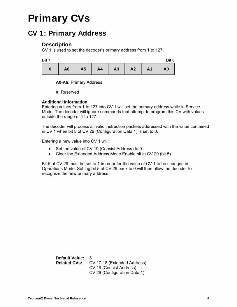
CV 1: Primary Address Description CV 1 is used to set the decoder’s primary address from 1 to 127. Bit 7 Bit 0
0 A6 A5 A4 A3 A2 A1 A0
A0-A6: Primary Address 0: Reserved
Additional Information Entering values from 1 to 127 into CV 1 will set the primary address while in Service Mode. The decoder will ignore commands that attempt to program this CV with values outside the range of 1 to 127. The decoder will process all valid instruction packets addressed with the value contained in CV 1 when bit 5 of CV 29 (Configuration Data 1) is set to 0. Entering a new value into CV 1 will:
Set the value of CV 19 (Consist Address) to 0. Clear the Extended Address Mode Enable bit in CV 29 (bit 5).
Bit 5 of CV 29 must be set to 1 in order for the value of CV 1 to be changed in Operations Mode. Setting bit 5 of CV 29 back to 0 will then allow the decoder to recognize the new primary address.
Default Value: 3 Related CVs: CV 17-18 (Extended Address)
CV 19 (Consist Address) CV 29 (Configuration Data 1)

Primary CVs
Tsunami2 Diesel Technical Reference 7
CV 2: Vstart Description CV 2 is used to set the voltage level applied to the motor at speed-step 1. Bit 7 Bit 0
D7 D6 D5 D4 D3 D2 D1 D0
D0-D7: Motor Start Voltage
Additional Information The motor start voltage is calculated as a fraction of the available supply voltage. Entering a value from 0 to 255 into CV 2 will adjust the starting voltage level. Starting voltage is calculated as:
Starting Voltage = Supply Voltage × CV 2 ÷ 255 When CV 2 is set to a non-zero value, the decoder will offset all points of the speed table as speed increases. CV 2 is used in conjunction with CV 5 (Vhigh) and CV 6 (Vmid) to configure the 3-point speed table. The 3-point speed table is active when bit 4 (STE) of CV 29 is set to 0 and CVs 2, 5, and 6 are set to non-zero values.
Default Value: 0 Related CVs: CV 5 (Vhigh)
CV 6 (Vmid) CV 29 (Configuration Data 1)
Primary CVs
Tsunami2 Diesel Technical Reference 8
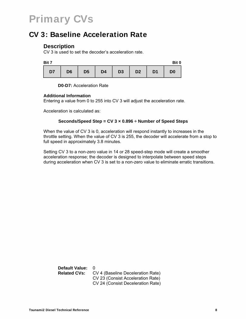
CV 3: Baseline Acceleration Rate Description CV 3 is used to set the decoder’s acceleration rate. Bit 7 Bit 0
D7 D6 D5 D4 D3 D2 D1 D0
D0-D7: Acceleration Rate
Additional Information Entering a value from 0 to 255 into CV 3 will adjust the acceleration rate. Acceleration is calculated as:
Seconds/Speed Step = CV 3 × 0.896 ÷ Number of Speed Steps When the value of CV 3 is 0, acceleration will respond instantly to increases in the throttle setting. When the value of CV 3 is 255, the decoder will accelerate from a stop to full speed in approximately 3.8 minutes. Setting CV 3 to a non-zero value in 14 or 28 speed-step mode will create a smoother acceleration response; the decoder is designed to interpolate between speed steps during acceleration when CV 3 is set to a non-zero value to eliminate erratic transitions.
Default Value: 0 Related CVs: CV 4 (Baseline Deceleration Rate)
CV 23 (Consist Acceleration Rate)CV 24 (Consist Deceleration Rate)

Primary CVs
Tsunami2 Diesel Technical Reference 9
CV 4: Baseline Deceleration Rate Description CV 4 is used to set the decoder’s deceleration rate. Bit 7 Bit 0
D7 D6 D5 D4 D3 D2 D1 D0
D0-D7: Deceleration Rate
Additional Information Entering a value from 0 to 255 into CV 4 will adjust the deceleration rate. Deceleration is calculated as:
Seconds/Speed Step = CV 4 × 0.896 ÷ Number of Speed Steps When the value of CV 4 is 0, deceleration will respond instantly to decreases in the throttle setting. When the value of CV 4 is 255, the decoder will decelerate from full speed to a stop in approximately 3.8 minutes. Setting CV 4 to a non-zero value in 14 or 28 speed-step mode will create a smoother deceleration response; the decoder is designed to interpolate between speed steps during deceleration when CV 4 is set to a non-zero value to eliminate erratic transitions.
Default Value: 0 Related CVs: CV 3 (Baseline Acceleration Rate)
CV 23 (Consist Acceleration Rate)CV 24 (Consist Deceleration Rate)CV 117 (Independent Brake Rate)

Primary CVs
Tsunami2 Diesel Technical Reference 10
CV 5: Vhigh Description CV 5 is used to set the voltage level applied to the motor at maximum speed and is active when the 3-point speed table is enabled. Bit 7 Bit 0
D7 D6 D5 D4 D3 D2 D1 D0
D0-D7: Maximum Voltage Value
Additional Information Maximum voltage is calculated as a fraction of the available supply voltage. Entering a value from 0 to 255 into CV 5 will adjust the maximum speed voltage level. Maximum voltage is calculated as:
Maximum Voltage = Supply Voltage × CV 5 ÷ 255 Values of 0 and 1 will disable the Vhigh speed table setting. A value of 255 will set the Vhigh speed table setting to the maximum available voltage (100%). CV 5 is used in conjunction with CV 2 (Vstart) and CV 6 (Vmid) to configure the 3-point speed table. The 3-point speed table is active when bit 4 (STE) of CV 29 is set to 0 and CVs 2, 5, and 6 are set to non-zero values.
Default Value: 0 Related CVs: CV 2 (Vstart)
CV 6 (Vmid) CV 29 (Configuration Data 1)

Primary CVs
Tsunami2 Diesel Technical Reference 11
CV 6: Vmid Description CV 6 is used to set the voltage level applied to the motor at the middle speed step and is active when the 3-point speed table is enabled. Bit 7 Bit 0
D7 D6 D5 D4 D3 D2 D1 D0
D0-D7: Midpoint Voltage Value
Additional Information Midpoint voltage is calculated as a fraction of the available supply voltage. Entering a value from 0 to 255 into CV 6 will adjust the mid-speed voltage level. Midpoint voltage is calculated as:
Midpoint Voltage = Supply Voltage × CV 6 ÷ 255 Values of 0 and 1 will disable the Vmid speed table setting. A value of 255 will set the Vmid speed table setting to the maximum available voltage (100%). CV 6 is used in conjunction with CV 2 (Vstart) and CV 5 (Vhigh) to configure the 3-point speed table. The 3-point speed table is active when bit 4 (STE) of CV 29 is set to 0 and CVs 2, 5, and 6 are set to non-zero values.
Default Value: 0 Related CVs: CV 2 (Vstart)
CV 5 (Vhigh) CV 29 (Configuration Data 1)

Primary CVs
Tsunami2 Diesel Technical Reference 12
CV 7: Manufacturer Version (Read-Only) Description CV 7 contains the 8-bit software version identifier. CV 7 is read-only and cannot be modified. Bit 7 Bit 0
D7 D6 D5 D4 D3 D2 D1 D0
D0-D7: Version Code
71 = Tsunami2 software version identifier

Primary CVs
Tsunami2 Diesel Technical Reference 13
CV 8: Manufacturer ID Description CV 8 is used to reset CV settings to factory defaults and contains the NMRA-issued Manufacturer ID Code (141) assigned to SoundTraxx/Throttle Up! Entering a value from 8 to 13 into CV 8 will reset the CVs defined below. Bit 7 Bit 0
1 0 0 0 1 1 0 1
Bits 0-7: CV Reset
8 = Full CV reset 9 = Reset CVs 1-128
10 = Reset CVs 129-256 11 = Reset CVs 1.257-1.51212 = Reset CVs 2.257-2.51213 = Reset CVs 3.257-3.512
Manufacturer ID Code: 141

Primary CVs
Tsunami2 Diesel Technical Reference 14
CV 10: EMF Feedback Cutout Description CV 10 is used to gradually reduce back-EMF control as locomotive speed increases. Bit 7 Bit 0
D7 D6 D5 D4 D3 D2 D1 D0
D0-D7: EMF Feedback Cutout
Additional Information The BEMF intensity is defined as the amount of the BEMF signal that is fed back to the motor controller to stabilize the speed of the motor. Reducing the intensity does not regulate the speed of the motor as effectively, but helps consisted locomotives from entering a ‘push/pull’ scenario where one locomotive is doing all the work. Per the equation below, this CV sets the speed step at which the intensity reaches zero. When CV 10 is set to 0, only the value in CV 212 is used.
BEMF Intensity = CV 212 x (1 – (speed step ÷ CV 10)) ÷ 255
Default Value: 0 Related CVs: CV 212 (BEMF Feedback Intensity)
CV 213 (BEMF Sample Period) CV 214 (BEMF Sample Aperture Time)CV 215 (BEMF Reference Voltage)

Primary CVs
Tsunami2 Diesel Technical Reference 15
CV 11: Packet Time-Out Value Description CV 11 is used to set duration in seconds that occurs from the time the decoder receives a valid packet to the time speed-related sound effects and motor processes are deactivated. Bit 7 Bit 0
D7 D6 D5 D4 D3 D2 D1 D0
D0-D7: Packet Time-Out Value
Additional Information Entering a value from 0 to 255 into CV 11 will set the packet time-out period. The time-out period is calculated in seconds as follows:
Time-Out Period = CV 11 × 0.25 A value of 0 disables the time-out period. A value of 255 sets the time-out period to approximately 1 minute. The decoder maintains an internal timer that resets each time the decoder receives a valid packet. In the event no valid packets are received during the time-out period, the decoder will deactivate motor processes and the locomotive will decelerate according to the value of CV 4 (Baseline Deceleration Rate) or CV 24 (Consist Deceleration Rate).
Default Value: 0

Primary CVs
Tsunami2 Diesel Technical Reference 16
CV 12: Alternate Power Source Description CV 12 is used to allow the decoder to operate using an analog power supply when a DCC signal is not available. Bit 3 (APS) of CV 29 (Configuration Data 1) must be set to 1 in order for an alternate power source to be used. Bit 7 Bit 0
0 0 0 0 0 0 0 D0
D0: Alternate Power Source
0 = No alternate power source 1 = Analog power supply
0: Reserved
Default Value: 1 Related CVs: CV 29 (Configuration Data 1)

Primary CVs
Tsunami2 Diesel Technical Reference 17
CV 13: Analog Mode Function Enable 1 Description CV 13 is used to enable F1-F8 function assignments for analog mode operation. Refer to CVs 1.257-1.384 (Effect Map Registers) and/or CVs 33-46 (Function Status CVs) for information regarding function mapping. Bit 7 Bit 0
F8 F7 F6 F5 F4 F3 F2 F1
F1-F8: Analog Mode Function Enable
0 = Function disabled for analog operation 1 = Function enabled for analog operation
Additional Information Setting bits 0-7 to 1 will enable the F1-F8 functions active in CVs 1.257-1.384 and/or CVs 33-46 for analog mode operation. Note: To access Indexed CV Page 1 with CVs 257-512, CV 31 (CV Index 1) must be set to a value of 16 (default) and CV 32 (CV Index 2) must be set to a value of 1 (default).
Default Value: 0 Related CVs: CV 14 (Analog Mode Function Enable 2)
CV 33-46 (Function Status CVs) CV 241-243 (Analog Mode Function Enable 3-5) CV 1.257-1.512 (Extended Function Mapping CVs)
Primary CVs
Tsunami2 Diesel Technical Reference 18
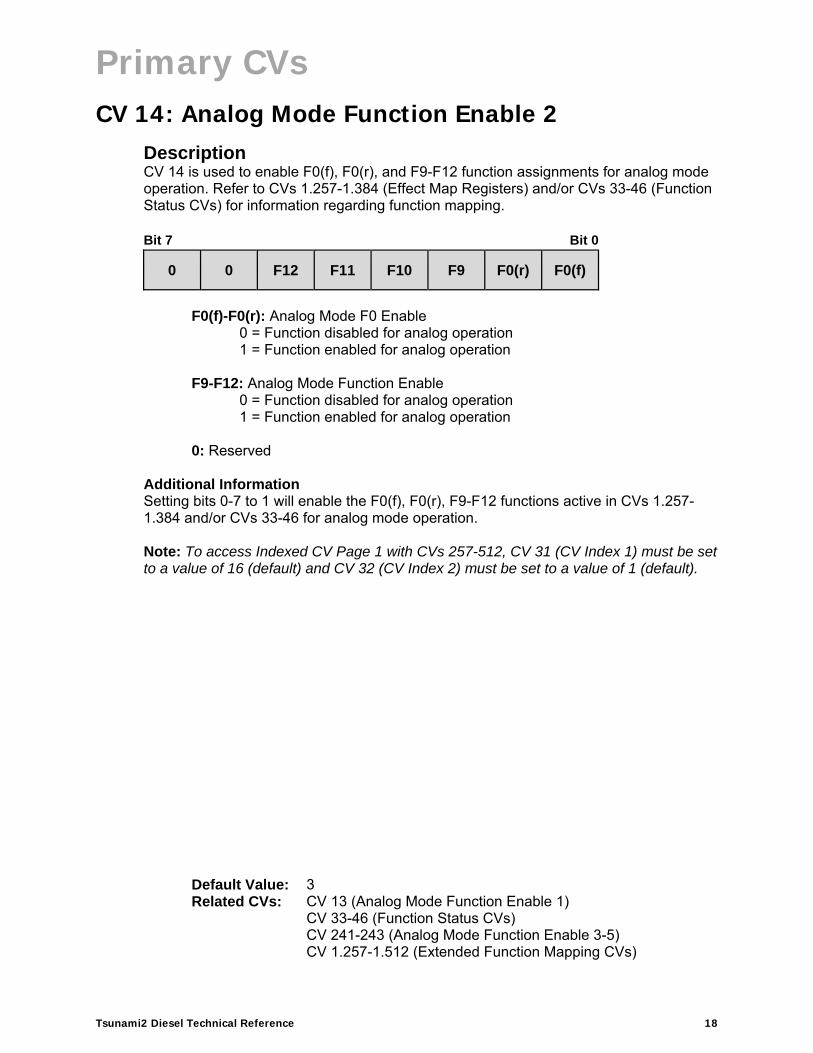
CV 14: Analog Mode Function Enable 2 Description CV 14 is used to enable F0(f), F0(r), and F9-F12 function assignments for analog mode operation. Refer to CVs 1.257-1.384 (Effect Map Registers) and/or CVs 33-46 (Function Status CVs) for information regarding function mapping. Bit 7 Bit 0
0 0 F12 F11 F10 F9 F0(r) F0(f)
F0(f)-F0(r): Analog Mode F0 Enable
0 = Function disabled for analog operation 1 = Function enabled for analog operation
F9-F12: Analog Mode Function Enable
0 = Function disabled for analog operation 1 = Function enabled for analog operation
0: Reserved
Additional Information Setting bits 0-7 to 1 will enable the F0(f), F0(r), F9-F12 functions active in CVs 1.257-1.384 and/or CVs 33-46 for analog mode operation. Note: To access Indexed CV Page 1 with CVs 257-512, CV 31 (CV Index 1) must be set to a value of 16 (default) and CV 32 (CV Index 2) must be set to a value of 1 (default).
Default Value: 3 Related CVs: CV 13 (Analog Mode Function Enable 1)
CV 33-46 (Function Status CVs) CV 241-243 (Analog Mode Function Enable 3-5) CV 1.257-1.512 (Extended Function Mapping CVs)

Primary CVs
Tsunami2 Diesel Technical Reference 19
CV 15: CV Unlock Code Description CV 15 is used for unlocking access to the decoder’s CVs. Bit 7 Bit 0
0 0 0 0 0 D2 D1 D0
D0-D2: CV Unlock Code
0: Reserved
Additional Information Entering a value from 0 to 7 into CV 15 determines the decoder’s lock status. CV 15 can be accessed regardless of the decoder’s lock status. Locked State: If the value of CV 15 is not equal to the value of CV 16 (CV Lock ID), all CVs are locked. Read and write operations will be ignored. Unlocked State: The decoder’s CVs can be accessed only when the value of CV 15 is equal to the value of CV 16. Note: Bit 0 (CV Lock Enable) of CV 30 (Error Information) must be set to 1 in order for the lock feature in CVs 15 and 16 to be used.
Default Value: 0 Related CVs: CV 16 (CV Lock ID)
CV 30 (Error Information)

Primary CVs
Tsunami2 Diesel Technical Reference 20
CV 16: CV Lock ID Description CV 16 is used in conjunction with CV 15 (CV Unlock Code) to determine the decoder’s lock status. CV 16 determines the lock code used to lock the decoder’s CVs. Bit 7 Bit 0
0 0 0 0 0 ID2 ID1 ID0
ID0-ID2: CV Lock Code 0: Reserved
Additional Information Entering a value from 0 to 7 into CV 16 determines the decoder’s lock status. CV 16 can be accessed regardless of the decoder’s lock status. Locked State: If the value of CV 16 is not equal to the value of CV 15 (CV Unlock Code), all CVs are locked and all read and write operations will be ignored. Unlocked State: The decoder’s CVs will only be accessible when the value of CV 15 is equal to the value of CV 16. Note: Bit 0 (CV Lock Enable) of CV 30 (Error Information) must be set to 1 in order for the lock feature in CVs 15 and 16 to be used.
Default Value: 0 Related CVs: CV 15 (CV Unlock Code)
CV 30 (Error Information)
Primary CVs
Tsunami2 Diesel Technical Reference 21
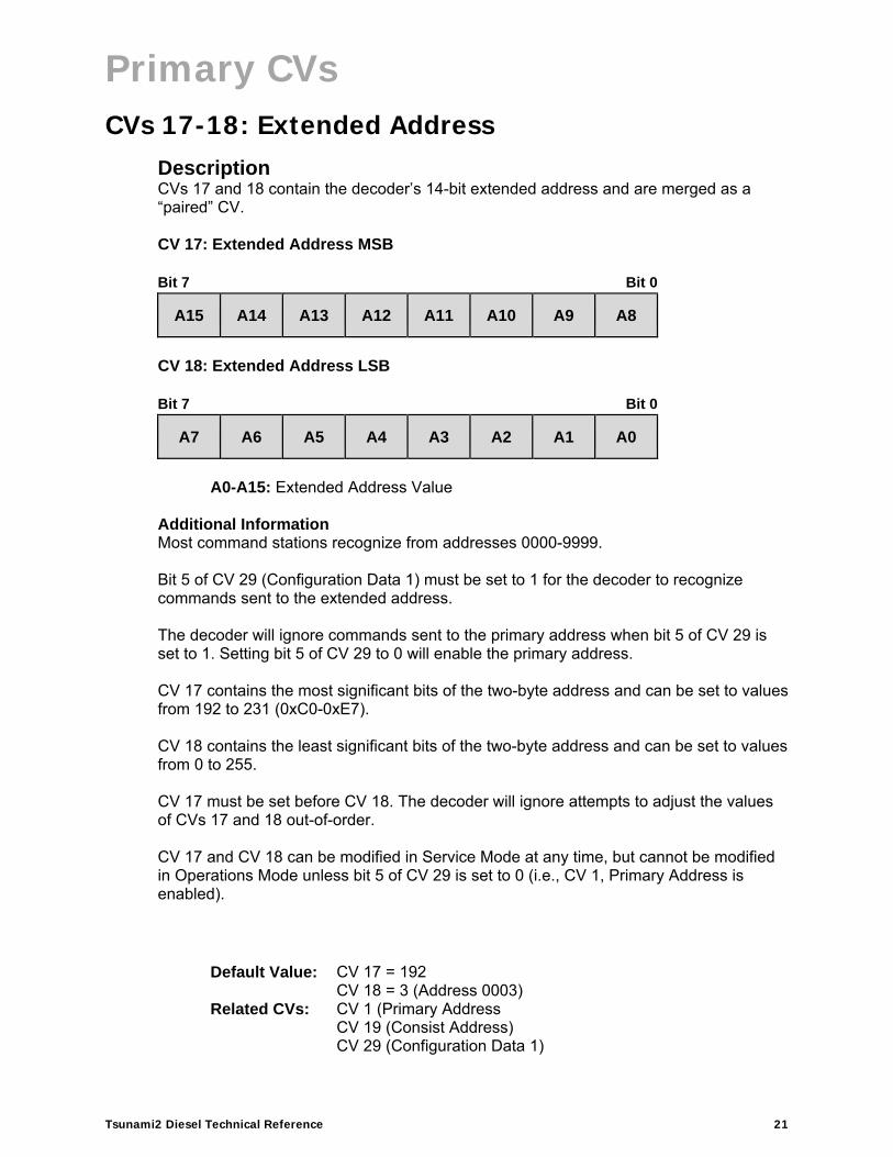
CVs 17-18: Extended Address Description CVs 17 and 18 contain the decoder’s 14-bit extended address and are merged as a “paired” CV. CV 17: Extended Address MSB Bit 7 Bit 0
A15 A14 A13 A12 A11 A10 A9 A8
CV 18: Extended Address LSB Bit 7 Bit 0
A7 A6 A5 A4 A3 A2 A1 A0
A0-A15: Extended Address Value
Additional Information Most command stations recognize from addresses 0000-9999. Bit 5 of CV 29 (Configuration Data 1) must be set to 1 for the decoder to recognize commands sent to the extended address. The decoder will ignore commands sent to the primary address when bit 5 of CV 29 is set to 1. Setting bit 5 of CV 29 to 0 will enable the primary address. CV 17 contains the most significant bits of the two-byte address and can be set to values from 192 to 231 (0xC0-0xE7). CV 18 contains the least significant bits of the two-byte address and can be set to values from 0 to 255. CV 17 must be set before CV 18. The decoder will ignore attempts to adjust the values of CVs 17 and 18 out-of-order. CV 17 and CV 18 can be modified in Service Mode at any time, but cannot be modified in Operations Mode unless bit 5 of CV 29 is set to 0 (i.e., CV 1, Primary Address is enabled).
Default Value: CV 17 = 192 Related CVs:
CV 18 = 3 (Address 0003) CV 1 (Primary Address CV 19 (Consist Address) CV 29 (Configuration Data 1)

Primary CVs
Tsunami2 Diesel Technical Reference 22
CV 19: Consist Address Description CV 19 is used to set the address and direction for advanced consist operation. Bit 7 Bit 0
CDIR A6 A5 A4 A3 A2 A1 A0
A0-A6: Consist Address Value
CDIR: Consist Direction
0 = Normal direction 1 = Inverted direction
Additional Information Bits 0-6 (A0-A6) are used to assign the consist address from 1 to 127. Setting bit 7 (CDIR) to 1 will invert consist direction. Entering a value from 1 to 127 will set the consist address from 1 to 127 for the normal direction. Entering a value from 129 to 255 will set the consist address from 1 to 127 for the inverted direction. Setting CV 19 to 0 or 128 will disable the consist address. When CV 19 is set to a non-zero value, the decoder will ignore throttle commands sent to the decoder’s primary or extended address. The decoder will process valid commands sent to the consist address with the following exceptions:
Long-form CV access instructions will be ignored.
The direction of a speed/direction command or an advanced operation command will be inverted when bit 7 (CDIR) is set to 1.
Default Value: 0 Related CVs: CV 1 (Primary Address)
CVs 17-18 (Extended Address) CVs 21-22 (Consist Function Enable 1-2) CV 23 (Consist Acceleration Rate) CV 24 (Consist Deceleration Rate) CVs 245-247 (Consist Function Enable 3-5)

Primary CVs
Tsunami2 Diesel Technical Reference 23
CV 21: Consist Function Enable 1 Description CV 21 is used to enable F1-F8 function assignments for advanced consist operation. Refer to CVs 1.257-1.384 (Effect Map Registers) and/or CVs 33-46 (Function Status CVs) for more information regarding function mapping. Bit 7 Bit 0
F8 F7 F6 F5 F4 F3 F2 F1
F1-F8: Consist Function Enable
0 = Function disabled for consist operation 1 = Function enabled for consist operation
Additional Information CV 21 is commonly used to differentiate various engines and cars of the same consist. Setting bits 0-7 to 1 will enable the F1-F8 functions active in CVs 1.257-1.384 and/or CVs 33-46 for advanced consist operation.
Note: To access Indexed CV Page 1 with CVs 257-512, CV 31 (CV Index 1) must be set to a value of 16 (default) and CV 32 (CV Index 2) must be set to a value of 1 (default).
Default Value: 0 Related CVs: CV 19 (Consist Function Enable 2)
CVs 33-46 (Function Status CVs) CVs 245-247 (Consist Function Enable 3-5) CVs 1.257-1.512 (Extended Function Mapping CVs)

Primary CVs
Tsunami2 Diesel Technical Reference 24
CV 22: Consist Function Enable 2 Description CV 22 is used to enable F0(f), F0(r), and F9-F12 function assignments for advanced consist operation. Refer to CVs 1.257-1.384 (Effect Map Registers) and/or CVs 33-46 (Function Status CVs) for more information regarding function mapping. Bit 7 Bit 0
0 0 F12 F11 F10 F9 F0(r) F0(f)
F0(f)-F0(r): Consist F0 Enable
0 = Function disabled for consist operation 1 = Function enabled for consist operation
F9-F12: Consist Function Enable
0 = Function disabled for consist operation 1 = Function enabled for consist operation
0: Reserved
Additional information CV 22 is commonly used to differentiate various engines and cars of the same consist. Setting bits 0-7 to 1 will enable the F0(f), F0(r), and F9-F12 functions active in CVs 1.257-1.384 and/or CVs 33-46 for advanced consist operation.
Note: To access Indexed CV Page 1 with CVs 257-512, CV 31 (CV Index 1) must be set to a value of 16 (default) and CV 32 (CV Index 2) must be set to a value of 1 (default).
Default Value: 0 Related CVs: CV 19 (Consist Address)
CV 21 (Consist Function Enable 1) CVs 33-46 (Function Status CVs) CVs 245-247 (Consist Function Enable 3-5) CVs 1.257-1.512 (Extended Function Mapping CVs)

Primary CVs
Tsunami2 Diesel Technical Reference 25
CV 23: Consist Acceleration Rate Description CV 23 is used to set the consist acceleration rate. CV 19 must contain a valid consist address for the consist acceleration rate to be active. Bit 7 Bit 0
SIGN D6 D5 D4 D3 D2 D1 D0
D0-D6: Consist Acceleration Offset SIGN: Sign
0 = Positive value 1 = Negative value
Additional Information The value of CV 23 determines the consist acceleration rate in relation to CV 3 (Baseline Acceleration Rate). When the consist address is active, the consist acceleration rate is added to or subtracted from the decoder’s baseline acceleration rate depending on the sign bit. Entering a value from 1 to 127 into CV 23 will increase the consist acceleration rate from the baseline acceleration rate in CV 3. Entering values from 129 to 255 into CV 23 will decrease the consist acceleration rate from the baseline acceleration rate in CV 3. Values of 0 and 128 will disable the consist acceleration rate and the decoder will use the value in CV 3.
When bit 7 (SIGN) of CV 23 is set to 0, the value added to CV 3 will be positive, where if bit 7 is set to 1, the value added to CV 3 will be negative:
0-127 128-255
0 = 0 128 = 0
1 = 1 129 = -1 . . .
. . .
127 = 127 255 = -127
Acceleration is calculated as:
Seconds/Speed Step = (CV 3 + CV 23) × 0.896 ÷ Number of Speed Steps
Default Value: 0 Related CVs: CV 3 (Baseline Acceleration Rate)
CV 4 (Baseline Deceleration Rate)CV 19 (Consist Address) CV 24 (Consist Deceleration Rate)

Primary CVs
Tsunami2 Diesel Technical Reference 26
CV 24: Consist Deceleration Rate Description CV 24 is used to set the consist deceleration rate. CV 19 must contain a valid consist address for the consist deceleration rate to be active. Bit 7 Bit 0
SIGN D6 D5 D4 D3 D2 D1 D0
D0-D6: Consist Deceleration Offset SIGN: Sign
0 = Positive value 1 = Negative value
Additional Information The value of CV 24 determines the consist deceleration rate in relation to CV 4 (Baseline Deceleration Rate). When the consist address is active, the consist deceleration rate is added to or subtracted from the decoder’s baseline deceleration rate depending on the sign bit. Entering a value from 1 to 127 into CV 24 will increase the consist deceleration rate from the baseline deceleration rate in CV 4. Entering values from 129 to 255 into CV 24 will decrease the consist deceleration rate from the baseline deceleration rate in CV 4. Values of 0 and 128 will disable the consist deceleration rate and the decoder will use the value in CV 3.
When bit 7 (SIGN) of CV 24 is set to 0, the value added to CV 4 will be positive, where if bit 7 is set to 1, the value added to CV 4 will be negative:
0-127 128-255
0 = 0 128 = 0
1 = 1 129 = -1 . . .
. . .
127 = 127 255 = -127
Deceleration is calculated as:
Seconds/Speed Step = (CV 4 + CV 24) × 0.896 ÷ Number of Speed Steps
Default Value: 0 Related CVs: CV 3 (Baseline Acceleration Rate)
CV 4 (Baseline Deceleration Rate)CV 19 (Consist Address) CV 23 (Consist Acceleration Rate)
Primary CVs
Tsunami2 Diesel Technical Reference 27
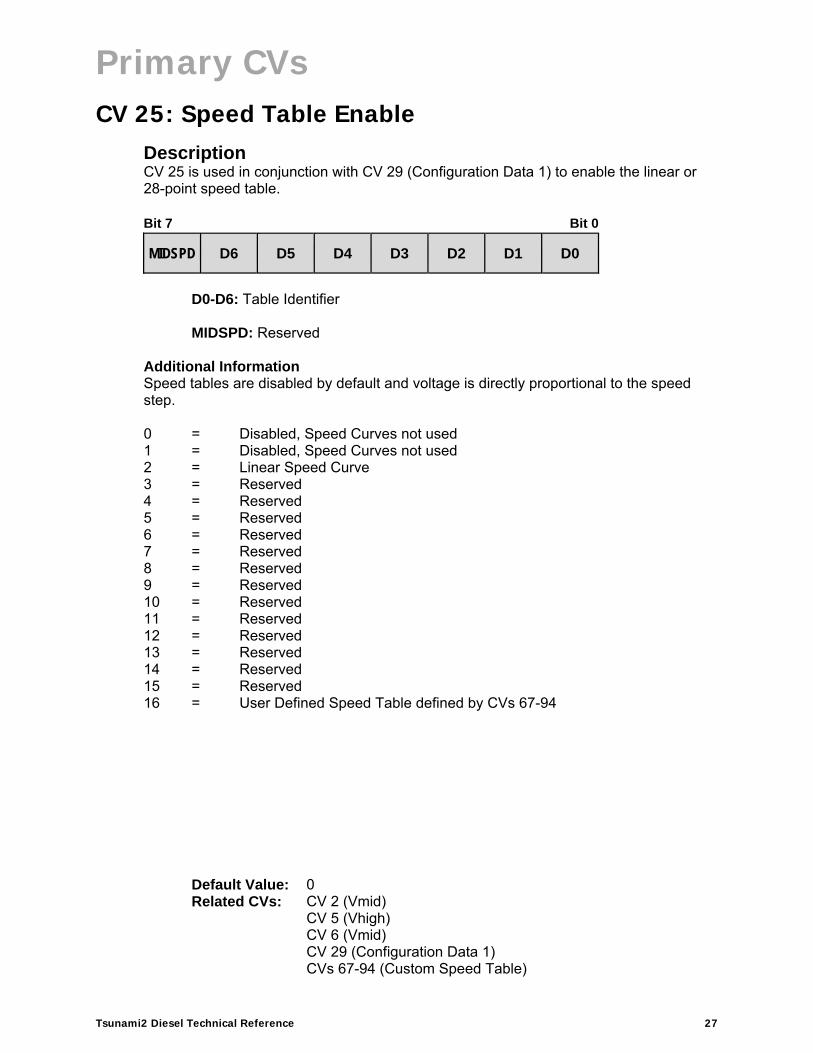
CV 25: Speed Table Enable Description CV 25 is used in conjunction with CV 29 (Configuration Data 1) to enable the linear or 28-point speed table. Bit 7 Bit 0
MIDSPD D6 D5 D4 D3 D2 D1 D0
D0-D6: Table Identifier
MIDSPD: Reserved
Additional Information Speed tables are disabled by default and voltage is directly proportional to the speed step. 0 = Disabled, Speed Curves not used 1 = Disabled, Speed Curves not used 2 = Linear Speed Curve 3 = Reserved 4 = Reserved 5 = Reserved 6 = Reserved 7 = Reserved 8 = Reserved 9 = Reserved 10 = Reserved 11 = Reserved 12 = Reserved 13 = Reserved 14 = Reserved 15 = Reserved 16 = User Defined Speed Table defined by CVs 67-94
Default Value: 0 Related CVs: CV 2 (Vmid)
CV 5 (Vhigh) CV 6 (Vmid) CV 29 (Configuration Data 1) CVs 67-94 (Custom Speed Table)
Primary CVs
Tsunami2 Diesel Technical Reference 28
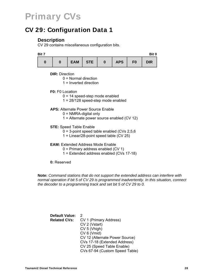
CV 29: Configuration Data 1 Description CV 29 contains miscellaneous configuration bits. Bit 7 Bit 0
0 0 EAM STE 0 APS F0 DIR
DIR: Direction
0 = Normal direction 1 = Inverted direction
F0: F0 Location
0 = 14 speed-step mode enabled 1 = 28/128 speed-step mode enabled
APS: Alternate Power Source Enable
0 = NMRA-digital only 1 = Alternate power source enabled (CV 12)
STE: Speed Table Enable
0 = 3-point speed table enabled (CVs 2,5,6 1 = Linear/28-point speed table (CV 25)
EAM: Extended Address Mode Enable
0 = Primary address enabled (CV 1) 1 = Extended address enabled (CVs 17-18)
0: Reserved
Note: Command stations that do not support the extended address can interfere with normal operation if bit 5 of CV 29 is programmed inadvertently. In this situation, connect the decoder to a programming track and set bit 5 of CV 29 to 0.
Default Value: 2 Related CVs: CV 1 (Primary Address)
CV 2 (Vstart) CV 5 (Vhigh) CV 6 (Vmid) CV 12 (Alternate Power Source) CVs 17-18 (Extended Address) CV 25 (Speed Table Enable) CVs 67-94 (Custom Speed Table)

Primary CVs
Tsunami2 Diesel Technical Reference 29
CV 30: Error Information Description CV 30 is used to allow the decoder’s CVs to be locked and unlocked with CV 15 (CV Unlock Code) and CV 16 (CV Lock ID). Bit 7 Bit 0
0 0 0 0 0 0 0 LCK
LCK: CV Lock/Unlock Enable
0 = CV lock/unlock feature disabled 1 = CV lock/unlock feature enabled (CVs 15-16)
0: Reserved
Default Value: 0 Related CVs: CV 15 (CV Unlock Code)
CV 16 (CV Lock ID)

Primary CVs
Tsunami2 Diesel Technical Reference 30
CV 31: CV Index 1 Description CV 31 and CV 32 (CV Index 2) contain the indexed address used for accessing CVs exceeding CV 256. CV 31 contains the most significant bits of the two-byte address and enables indexed CV operation, as determined by CV 32. Note: Modifying the default value of CV 31 will disable indexed CV operation; CV 31 should never be programmed from its default value. Bit 7 Bit 0
D7 D6 D5 D4 D3 D2 D1 D0
D0-D7: CV Index MSB
16 = Indexed address
Default Value: 16 Related CVs: CV 32 (CV Index 2)

Primary CVs
Tsunami2 Diesel Technical Reference 31
CV 32: CV Index 2 Description CV 32 provides access to CVs exceeding CV 256 and is used to select the active indexed CV page. Tsunami2 supports three indexed CV pages:
1. CVs 1.257-1.512: Indexed CV Page 1 2. CVs 2.257-2.512: Indexed CV Page 2 3. CVs 3.257-3.512: Indexed CV Page 3
The value of CV 32 indicates the active indexed CV page. CVs 257-512 allow access to indexed CVs when an indexed CV page is selected in CV 32. Bit 7 Bit 0
D7 D6 D5 D4 D3 D2 D1 D0
D0-D7: CV Index LSB
1 = Indexed CV Page 12 = Indexed CV Page 23 = Indexed CV Page 3
Additional Information Entering a value of 1 into CV 32 will select Indexed CV Page 1 as the active indexed CV page. Indexed CV Page 1 contains Flex-Map function mapping CVs:
CVs 1.257-1.384: Effect Map Registers CVs 1.385-1.512: Effect Auxiliary Map Registers
Entering a value of 2 into CV 32 will select Indexed CV Page 2 as the active indexed CV page. Indexed CV Page 2 contains alternate mixer channel volume control CVs and Dynamic Digital Exhaust control CVs:
CVs 2.289-2.320: Alternate Mixer Volume Levels CVs 2.503-2.512: DDE Control CVs
Entering a value of 3 into CV 32 will select Indexed CV Page 3 as the active indexed CV page. Indexed CV Page 3 contains clickety-clack CVs:
CV 3.257: Clickety-Clack Rate CV 3.258: Clickety-Clack Sound Scalar
Entering a value of 0 or values from 4 to 255 into CV 32 will disable access to CVs exceeding CV 256. If your system does not allow access to CVs exceeding CV 256, contact the manufacturer for more information.
Default Value: 1 Related CVs: CV 31 (CV Index 1)
CVs 1.257-1.512 (Extended Function Mapping CVs) CVs 2.289-2.320 (Alternate Mixer Volume Levels) CVs 2.503-2.512 (DDE Control CVs) CV 3.257 (Clickety-Clack Rate) CV 3.258 (Clickety-Clack Sound Scalar)

Primary CVs
Tsunami2 Diesel Technical Reference 32
CVs 33-46: Function Status CVs Function Status CVs 33-46 can be used to map a limited range of effects to functions F0-F12 and are included to remain consistent with NMRA Standards for DCC Configuration Variables (S-9.2.2, p.7). Note: CVs 33-46 are set to values of 0 by default, are a secondary method of function mapping for those wishing to use the Legacy Function Mapping associated with the prior generation of Tsunami products, and are not used to determine Tsunami2’s default function assignments. CVs 1.257-1.512 (Flex-Map Function Mapping CVs) provide function assignments for 28 function keys and offer comprehensive function mapping support for all of Tsunami2’s effects in an uncomplicated and versatile format. However, mapping an effect to a function key (F0(f), F0(r), or F1-F12) using CVs 33-46 will override the corresponding function assignment mapped within CVs 1.257-1.384. Note: The use of Legacy Function Mapping and Flex-Map Function Mapping together may produce undesirable results and is not recommended. Effects mapped to CV 33 (F0(f) Output Location) can be activated in the forward direction only and effects mapped to CV 34 (F0(r) Output Location) can be activated in the reverse direction only. This output is bidirectional only when same effect has been mapped to both CVs. The function mapping table provided below indicates the values used for mapping functions to effects. All provided effects cannot be mapped to all F0-F12 functions keys.
Legacy Function Output Map
Fu
nct
ion
Key
CV
HL
Out
put
BL
Out
put
Airh
orn
Bel
l
FX
3 O
utpu
t
FX
4 O
utpu
t
Dyn
amic
Bra
ke
Sho
rt A
irhor
n
Str
aigh
t-to
-8
Gen
eral
Ser
vice
Dim
mer
Mut
e
HE
P M
ode
Ind.
/Tra
in B
rake
Cou
pler
F0(f) 33 1 2 4 8 16 32 64 128
F0(r) 34 1 2 4 8 16 32 64 128
F1 35 1 2 4 8 16 32 64 128
F2 36 1 2 4 8 16 32 64 128
F3 37
1 2 4 8 16 32 64 128
F4 38 1 2 4 8 16 32 64 128
F5 39 1 2 4 8 16 32 64 128
F6 40 1 2 4 8 16 32 64 128
F7 41
1 2 4 8 16 32 64 128
F8 42 1 2 4 8 16 32 64 128
F9 43 1 2 4 8 16 32 64 128
F10 44
1 2 4 8 16 32 64 128
F11 45 1 2 4 8 16 32 64 128
F12 46 1 2 4 8 16 32 64 128

Primary CVs
Tsunami2 Diesel Technical Reference 33
CV 33: F0(f) Output Location Description CV 33 is used to map a given effect to the F0(f) function key. The enabled effect will be activated when the F0(f) function is turned on. Disabled effects will have no relation to the F0(f) function key. Bit 7 Bit 0
SAH DYN FX4 FX3 BEL AH BL HL
HL: Headlight Output
0 = Headlight disabled 1 = Headlight enabled
BL: Backup Light Output
0 = Backup light disabled 1 = Backup light enabled
AH: Airhorn
0 = Airhorn disabled 1 = Airhorn enabled
BEL: Bell
0 = Bell disabled 1 = Bell enabled
FX3: FX3 Output
0 = FX3 disabled 1 = FX3 enabled
FX4: FX4 Output
0 = FX4 disabled 1 = FX4 enabled
DYN: Dynamic Brake
0 = Dynamic brake disabled 1 = Dynamic brake enabled
SAH: Short Airhorn
0 = Short airhorn disabled 1 = Short airhorn enabled
Default Value: 0

Primary CVs
Tsunami2 Diesel Technical Reference 34
CV 34: F0(r) Output Location Description CV 34 is used to map a given effect to the F0(r) function key. The enabled effect will be activated when the F0(r) function is turned on. Disabled effects will have no relation to the F0(r) function key. Bit 7 Bit 0
SAH DYN FX4 FX3 BEL AH BL HL
HL: Headlight Output
0 = Headlight disabled 1 = Headlight enabled
BL: Backup Light Output
0 = Backup light disabled 1 = Backup light enabled
AH: Airhorn
0 = Airhorn disabled 1 = Airhorn enabled
BEL: Bell
0 = Bell disabled 1 = Bell enabled
FX3: FX3 Output
0 = FX3 disabled 1 = FX3 enabled
FX4: FX4 Output
0 = FX4 disabled 1 = FX4 enabled
DYN: Dynamic Brake
0 = Dynamic brake disabled 1 = Dynamic brake enabled
SAH: Short Airhorn
0 = Short airhorn disabled 1 = Short airhorn enabled
Default Value: 0

Primary CVs
Tsunami2 Diesel Technical Reference 35
CV 35: F1 Output Location Description CV 35 is used to map a given effect to the F1 function key. The enabled effect will be activated when the F1 function is turned on. Disabled effects will have no relation to the F1 function key. Bit 7 Bit 0
SAH DYN FX4 FX3 BEL AH BL HL
HL: Headlight Output
0 = Headlight disabled 1 = Headlight enabled
BL: Backup Light Output
0 = Backup light disabled 1 = Backup light enabled
AH: Airhorn
0 = Airhorn disabled 1 = Airhorn enabled
BEL: Bell
0 = Bell disabled 1 = Bell enabled
FX3: FX3 Output
0 = FX3 disabled 1 = FX3 enabled
FX4: FX4 Output
0 = FX4 disabled 1 = FX4 enabled
DYN: Dynamic Brake
0 = Dynamic brake disabled 1 = Dynamic brake enabled
SAH: Short Airhorn
0 = Short airhorn disabled 1 = Short airhorn enabled
Default Value: 0

Primary CVs
Tsunami2 Diesel Technical Reference 36
CV 36: F2 Output Location Description CV 36 is used to map a given effect to the F2 function key. The enabled effect will be activated when the F2 function is turned on. Disabled effects will have no relation to the F2 function key. Bit 7 Bit 0
SAH DYN FX4 FX3 BEL AH BL HL
HL: Headlight Output
0 = Headlight disabled 1 = Headlight enabled
BL: Backup Light Output
0 = Backup light disabled 1 = Backup light enabled
AH: Airhorn
0 = Airhorn disabled 1 = Airhorn enabled
BEL: Bell
0 = Bell disabled 1 = Bell enabled
FX3: FX3 Output
0 = FX3 disabled 1 = FX3 enabled
FX4: FX4 Output
0 = FX4 disabled 1 = FX4 enabled
DYN: Dynamic Brake
0 = Dynamic brake disabled 1 = Dynamic brake enabled
SAH: Short Airhorn
0 = Short airhorn disabled 1 = Short airhorn enabled
Default Value: 0

Primary CVs
Tsunami2 Diesel Technical Reference 37
CV 37: F3 Output Location Description CV 37 is used to map a given effect to the F3 function key. The enabled effect will be activated when the F3 function is turned on. Disabled effects will have no relation to the F3 function key. Bit 7 Bit 0
DIM GS ST8 SAH DYN FX4 FX3 BEL
BEL: Bell
0 = Bell disabled 1 = Bell enabled
FX3: FX3 Output
0 = FX3 disabled 1 = FX3 enabled
FX4: FX4 Output
0 = FX4 disabled 1 = FX4 enabled
DYN: Dynamic Brake
0 = Dynamic brake disabled 1 = Dynamic brake enabled
SAH: Short Airhorn
0 = Short airhorn disabled 1 = Short airhorn enabled
ST8: Straight-to-8 0 = Straight-to-8 disabled 1 = Straight-to-8 enabled
GS: General Service 0 = General Service disabled 1 = General Service enabled
DIM: Dimmer 0 = Dimmer disabled 1 = Dimmer enabled
0: Reserved
Default Value: 0

Primary CVs
Tsunami2 Diesel Technical Reference 38
CV 38: F4 Output Location Description CV 38 is used to map a given effect to the F4 function key. The enabled effect will be activated when the F4 function is turned on. Disabled effects will have no relation to the F4 function key. Bit 7 Bit 0
DIM GS ST8 SAH DYN FX4 FX3 BEL
BEL: Bell
0 = Bell disabled 1 = Bell enabled
FX3: FX3 Output
0 = FX3 disabled 1 = FX3 enabled
FX4: FX4 Output
0 = FX4 disabled 1 = FX4 enabled
DYN: Dynamic Brake
0 = Dynamic brake disabled 1 = Dynamic brake enabled
SAH: Short Airhorn
0 = Short airhorn disabled 1 = Short airhorn enabled
ST8: Straight-to-8 0 = Straight-to-8 disabled 1 = Straight-to-8 enabled
GS: General Service 0 = General Service disabled 1 = General Service enabled
DIM: Dimmer 0 = Dimmer disabled 1 = Dimmer enabled
0: Reserved
Default Value: 0

Primary CVs
Tsunami2 Diesel Technical Reference 39
CV 39: F5 Output Location Description CV 39 is used to map a given effect to the F5 function key. The enabled effect will be activated when the F5 function is turned on. Disabled effects will have no relation to the F5 function key. Bit 7 Bit 0
DIM GS ST8 SAH DYN FX4 FX3 BEL
BEL: Bell
0 = Bell disabled 1 = Bell enabled
FX3: FX3 Output
0 = FX3 disabled 1 = FX3 enabled
FX4: FX4 Output
0 = FX4 disabled 1 = FX4 enabled
DYN: Dynamic Brake
0 = Dynamic brake disabled 1 = Dynamic brake enabled
SAH: Short Airhorn
0 = Short airhorn disabled 1 = Short airhorn enabled
ST8: Straight-to-8
0 = Straight-to-8 disabled 1 = Straight-to-8 enabled
GS: General Service 0 = General Service disabled 1 = General Service enabled
DIM: Dimmer 0 = Dimmer disabled 1 = Dimmer enabled
0: Reserved
Default Value: 0
Primary CVs
Tsunami2 Diesel Technical Reference 40
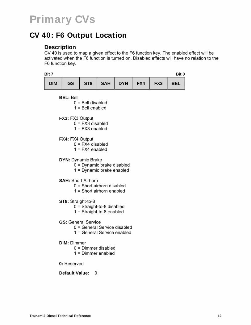
CV 40: F6 Output Location Description CV 40 is used to map a given effect to the F6 function key. The enabled effect will be activated when the F6 function is turned on. Disabled effects will have no relation to the F6 function key. Bit 7 Bit 0
DIM GS ST8 SAH DYN FX4 FX3 BEL
BEL: Bell
0 = Bell disabled 1 = Bell enabled
FX3: FX3 Output
0 = FX3 disabled 1 = FX3 enabled
FX4: FX4 Output
0 = FX4 disabled 1 = FX4 enabled
DYN: Dynamic Brake
0 = Dynamic brake disabled 1 = Dynamic brake enabled
SAH: Short Airhorn
0 = Short airhorn disabled 1 = Short airhorn enabled
ST8: Straight-to-8 0 = Straight-to-8 disabled 1 = Straight-to-8 enabled
GS: General Service 0 = General Service disabled 1 = General Service enabled
DIM: Dimmer 0 = Dimmer disabled 1 = Dimmer enabled
0: Reserved
Default Value: 0

Primary CVs
Tsunami2 Diesel Technical Reference 41
CV 41: F7 Output Location Description CV 41 is used to map a given effect to the F7 function key. The enabled effect will be activated when the F7 function is turned on. Disabled effects will have no relation to the F7 function key. Bit 7 Bit 0
BRK HEP MUT DIM GS ST8 SAH DYN
DYN: Dynamic Brake
0 = Dynamic brake disabled 1 = Dynamic brake enabled
SAH: Short Airhorn
0 = Short airhorn disabled 1 = Short airhorn enabled
ST8: Straight-to-8 0 = Straight-to-8 disabled 1 = Straight-to-8 enabled
GS: General Service 0 = General Service disabled 1 = General Service enabled
DIM: Dimmer
0 = Dimmer disabled 1 = Dimmer enabled
MUT: Mute 0 = Mute disabled 1 = Mute enabled
ST8: Straight-to-8 0 = Straight-to-8 disabled 1 = Straight-to-8 enabled
HEP: HEP Mode (Head-end Power) 0 = HEP Mode disabled 1 = HEP Mode enabled
BRK: Independent/Train Brake 0 = Independent/train brake disabled 1 = Independent/train brake enabled
0: Reserved
Default Value: 0

Primary CVs
Tsunami2 Diesel Technical Reference 42
CV 42: F8 Output Location Description CV 42 is used to map a given effect to the F8 function key. The enabled effect will be activated when the F8 function is turned on. Disabled effects will have no relation to the F8 function key. Bit 7 Bit 0
BRK HEP MUT DIM GS ST8 SAH DYN
DYN: Dynamic Brake
0 = Dynamic brake disabled 1 = Dynamic brake enabled
SAH: Short Airhorn
0 = Short airhorn disabled 1 = Short airhorn enabled
ST8: Straight-to-8 0 = Straight-to-8 disabled 1 = Straight-to-8 enabled
GS: General Service 0 = General Service disabled 1 = General Service enabled
DIM: Dimmer
0 = Dimmer disabled 1 = Dimmer enabled
MUT: Mute 0 = Mute disabled 1 = Mute enabled
HEP: HEP Mode (Head-end Power) 0 = HEP Mode disabled 1 = HEP Mode enabled
BRK: Independent/Train Brake
0 = Independent/train brake disabled 1 = Independent/train brake enabled
0: Reserved
Default Value: 0

Primary CVs
Tsunami2 Diesel Technical Reference 43
CV 43: F9 Output Location Description CV 43 is used to map a given effect to the F9 function key. The enabled effect will be activated when the F9 function is turned on. Disabled effects will have no relation to the F9 function key. Bit 7 Bit 0
BRK HEP MUT DIM GS ST8 SAH DYN
DYN: Dynamic Brake
0 = Dynamic brake disabled 1 = Dynamic brake enabled
SAH: Short Airhorn
0 = Short airhorn disabled 1 = Short airhorn enabled
ST8: Straight-to-8 0 = Straight-to-8 disabled 1 = Straight-to-8 enabled
GS: General Service 0 = General Service disabled 1 = General Service enabled
DIM: Dimmer
0 = Dimmer disabled 1 = Dimmer enabled
MUT: Mute 0 = Mute disabled 1 = Mute enabled
HEP: HEP Mode (Head-end Power) 0 = HEP Mode disabled 1 = HEP Mode enabled
BRK: Independent/Train Brake
0 = Independent/train brake disabled 1 = Independent/train brake enabled
0: Reserved
Default Value: 0

Primary CVs
Tsunami2 Diesel Technical Reference 44
CV 44: F10 Output Location Description CV 44 is used to map a given effect to the F10 function key. The enabled effect will be activated when the F10 function is turned on. Disabled effects will have no relation to the F10 function key. Bit 7 Bit 0
CPL BRK HEP MUT DIM GS ST8 SAH
SAH: Short Airhorn
0 = Short airhorn disabled 1 = Short airhorn enabled
ST8: Straight-to-8 0 = Straight-to-8 disabled 1 = Straight-to-8 enabled
GS: General Service 0 = General Service disabled 1 = General Service enabled
DIM: Dimmer
0 = Dimmer disabled 1 = Dimmer enabled
MUT: Mute 0 = Mute disabled 1 = Mute enabled
HEP: HEP Mode (Head-end Power) 0 = HEP Mode disabled 1 = HEP Mode enabled
BRK: Independent/Train Brake 0 = Independent/train brake disabled 1 = Independent/train brake enabled
CPL: Coupler 0 = Coupler disabled 1 = Coupler enabled
0: Reserved
Default Value: 0

Primary CVs
Tsunami2 Diesel Technical Reference 45
CV 45: F11 Output Location Description CV 45 is used to map a given effect to the F11 function key. The enabled effect will be activated when the F11 function is turned on. Disabled effects will have no relation to the F11 function key. Bit 7 Bit 0
CPL BRK HEP MUT DIM GS ST8 SAH
SAH: Short Airhorn
0 = Short airhorn disabled 1 = Short airhorn enabled
ST8: Straight-to-8 0 = Straight-to-8 disabled 1 = Straight-to-8 enabled
GS: General Service 0 = General Service disabled 1 = General Service enabled
DIM: Dimmer 0 = Dimmer disabled 1 = Dimmer enabled
MUT: Mute 0 = Mute disabled 1 = Mute enabled
HEP: HEP Mode (Head-end Power) 0 = HEP Mode disabled 1 = HEP Mode enabled
BRK: Independent/Train Brake 0 = Independent/train brake disabled 1 = Independent/train brake enabled
CPL: Coupler 0 = Coupler disabled 1 = Coupler enabled
0: Reserved
Default Value: 0

Primary CVs
Tsunami2 Diesel Technical Reference 46
CV 46: F12 Output Location Description CV 46 is used to map a given effect to the F12 function key. The enabled effect will be activated when the F12 function is turned on. Disabled effects will have no relation to the F12 function key. Bit 7 Bit 0
CPL BRK HEP MUT DIM GS ST8 SAH
SAH: Short Airhorn
0 = Short airhorn disabled 1 = Short airhorn enabled
ST8: Straight-to-8 0 = Straight-to-8 disabled 1 = Straight-to-8 enabled
GS: General Service 0 = General Service disabled 1 = General Service enabled
DIM: Dimmer 0 = Dimmer disabled 1 = Dimmer enabled
MUT: Mute 0 = Mute disabled 1 = Mute enabled
HEP: HEP Mode (Head-end Power) 0 = HEP Mode disabled 1 = HEP Mode enabled
BRK: Independent/Train Brake 0 = Independent/train brake disabled 1 = Independent/train brake enabled
CPL: Coupler 0 = Coupler disabled 1 = Coupler enabled
0: Reserved
Default Value: 0

Lighting Effect CVs
Tsunami2 Diesel Technical Reference 47
Lighting Effect CVs
CVs 49-54: Hyperlight Effect Select Description CVs 49-54 are used to configure up to six lighting outputs with Hyperlight lighting effects and other lighting features. Bit definitions for CVs 49-54 are identical.
CV 49: Headlight Configuration (F0(f) by default) CV 50: Backup Light Configuration (F0(r) by default)CV 51: FX3 Configuration (F24 by default) CV 52: FX4 Configuration (F25 by default) CV 53: FX5 Configuration (F26 by default) ** CV 54: FX6 Configuration (F27 by default) **
** Available on select formats
Bit 7 Bit 0
LED XING PHSE EF4 EF3 EF2 EF1 EF0
EF0-EF4: Hyperlight Effect Select
0 1 2 3 4 5 6 7 8 9
10 11 12 13 14 15 16 17 18 19 20 21 22 23 24 25
= On/off output = Dimmable headlight = Mars Light = Pyle-National Gyralite = Oscillating headlight = Single-flash strobe 1 = Double-flash strobe = Western-Cullen D312 Rotary Beacon = Prime Stratolite = Type I ditch light = Type II ditch light = Flashing rear-end device (FRED) = Engine exhaust flicker = Firebox flicker (steam) = Smart firebox flicker (steam) = Dyno-light = Auto-dim forward = Auto-dim reverse = Brake light = On/off – brightness 1 = On/off – brightness 2 = Emergency Gyralite = Electrical arcing (electric) = Ash pan flicker (steam) = Reserved = Single-flash strobe 2
Lighting Effect CVs
Tsunami2 Diesel Technical Reference 48
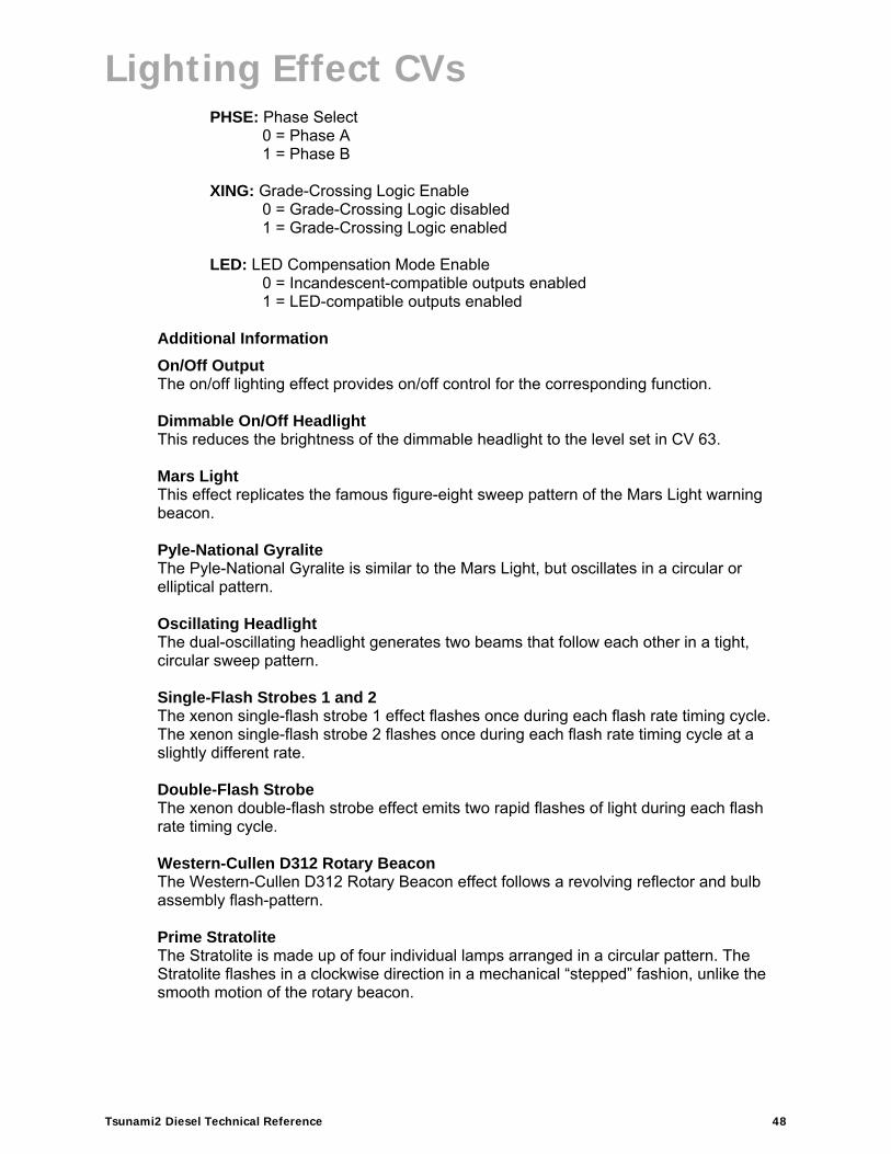
PHSE: Phase Select 0 = Phase A 1 = Phase B
XING: Grade-Crossing Logic Enable 0 = Grade-Crossing Logic disabled 1 = Grade-Crossing Logic enabled
LED: LED Compensation Mode Enable 0 = Incandescent-compatible outputs enabled 1 = LED-compatible outputs enabled
Additional Information
On/Off Output The on/off lighting effect provides on/off control for the corresponding function. Dimmable On/Off Headlight This reduces the brightness of the dimmable headlight to the level set in CV 63.
Mars Light This effect replicates the famous figure-eight sweep pattern of the Mars Light warning beacon. Pyle-National Gyralite The Pyle-National Gyralite is similar to the Mars Light, but oscillates in a circular or elliptical pattern. Oscillating Headlight The dual-oscillating headlight generates two beams that follow each other in a tight, circular sweep pattern. Single-Flash Strobes 1 and 2 The xenon single-flash strobe 1 effect flashes once during each flash rate timing cycle. The xenon single-flash strobe 2 flashes once during each flash rate timing cycle at a slightly different rate. Double-Flash Strobe The xenon double-flash strobe effect emits two rapid flashes of light during each flash rate timing cycle. Western-Cullen D312 Rotary Beacon The Western-Cullen D312 Rotary Beacon effect follows a revolving reflector and bulb assembly flash-pattern. Prime Stratolite The Stratolite is made up of four individual lamps arranged in a circular pattern. The Stratolite flashes in a clockwise direction in a mechanical “stepped” fashion, unlike the smooth motion of the rotary beacon.

Lighting Effect CVs
Tsunami2 Diesel Technical Reference 49
Ditch Lights I and II Ditch lights I and II flash together by default. When Grade-Crossing Logic is enabled, ditch light I assumes a steady “on” state before and after the crossing hold timer countdown. Conversely, ditch light II will remain off before and after the crossing hold timer countdown. To configure alternating ditch lights, set one lighting output to ditch light I or II and enable Grade-Crossing Logic, and then set a second lighting output to the same ditch light and enable Grade-Crossing Logic and phase offset. FRED (Flashing Rear End Device) The FRED effect is a flashing red taillight that indicates the rear of the train. Exhaust Flicker The exhaust flicker effect simulates a light flickering inside the cab. The flicker becomes more rapid and brighter as the locomotive emits higher volumes of exhaust to produce more power. The brightness of the flicker ranges from 0% to 100% in proportion to locomotive speed. Firebox Flicker The firebox flicker effect flickers at random to simulate the fire burning fuel in the firebox.
Dyno-Light This effect for diesel locomotives softly fades the lamp brightness on and off to simulate the heating and cooling of the bulb filament. Auto-Dim Forward and Reverse The auto-dim forward effect will automatically dim lighting outputs to the dimmer level in CV 63 when stopped or in the forward direction, and the auto-dim reverse effect will automatically dim lighting outputs to the dimmer level in CV 63 when stopped or in the reverse direction. Brake Light The brake light effect is dimmed to the brightness setting in CV 63 when active. The brake light brightness level will be automatically set to 100% when you turn on the independent or train brake function (F11 by default). On/Off Brightness 1 and 2 The on/off brightness 1 and 2 effects will set lighting outputs to the brightness levels of CVs 61 and 62, respectively. Emergency Gyralite The emergency Gyralite follows the same sweep pattern as the Gyralite, and will automatically disable all active lighting effects. Electrical Arcing (Electric) The electrical arcing effect flickers on and off to simulate the varying connection between the pantograph and overhead wire.

Lighting Effect CVs
Tsunami2 Diesel Technical Reference 50
Ash Pan Flicker (Steam) The ash pan flicker effect slowly flickers from 25% to 100% brightness to simulate the glowing embers that filter into the ash pan from the firebox.
Phase Offset Add a value of 32 to the value of flashing Hyperlight effects to set the corresponding lighting output to Phase B from Phase A. Flashing effects set to Phase B will flash opposite of flashing effects set to Phase A, i.e., Phase A turns off when Phase B turns on, and Phase A turns on when Phase B turns off. Grade-Crossing Logic Add a value of 64 to enable Grade-Crossing Logic. Turing on the long airhorn function (F2 by default) or the grade-crossing signal function (F9 by default) will start the crossing hold timer countdown and allow lighting effects to assume a flashing state. Flashing Hyperlight effects will return to an on or off state after the countdown ends. Adjust the crossing hold timer countdown from 0 to 15 seconds by entering a value from 0 to 15 into CV 60 (Grade-Crossing Hold Time). LED Compensation Mode The brightness of an incandescent bulb is determined by voltage, whereas an LED’s brightness is determined by current. LED Compensation Mode alters the method of sending current to the LED to balance the LED and incandescent brightness levels. Add a value of 128 to enable LED Compensation Mode for the corresponding lighting output. Note: Enabling LED Compensation Mode will not change the output voltage. Resistors may still be necessary depending on the board format.
Flashing Effect On/Off State Hyperlight Effect On/Off State Mars Light On Gyralite On Oscillating Headlight On Single-Flash Strobe 1 Off Single-Flash Strobe 2 Off Double-Flash Strobe Off D312 Rotary Beacon Off Prime Stratolite Off Ditch Light I On Ditch Light II Off FRED Off
Default Value: CVs 49-54 = 15

Lighting Effect CVs
Tsunami2 Diesel Technical Reference 51
CV 57: Forward Direction Enable Description CV 57 (Forward Direction Enable) and CV 58 (Reverse Direction Enable) are used to determine the directionality of the FX lighting outputs. Use CV 57 to enable a lighting output for the forward direction. Bit 7 Bit 0
0 0 FX6 FX5 FX4 FX3 BL HL
HL: Headlight Forward Enable
0 = Headlight output disabled in forward direction 1 = Headlight output enabled in forward direction
BL: Backup Light Forward Enable 0 = Backup light output disabled in forward direction 1 = Backup light output enabled in forward direction
FX3-FX6: FX3-FX6 Forward Enable 0 = FX output disabled in forward direction 1 = FX output enabled in forward direction
0: Reserved
Additional Information Setting bits 0-5 to 1 will enable the corresponding lighting output for the forward direction. A given lighting output can be made bidirectional by setting corresponding bits of CVs 57 and 58. Refer to indexed CVs 1.257-1.512 (Extended Function Mapping CVs) for information regarding mapping functions to lighting outputs.
Default Value: CV 49 = 1 CV 50 = 1 CVs 51-54 = 0
Related CVs: CVs 57-64 (Lighting Effect CVs)
Default Value: 253 Related CVs: CVs 49-54 (Hyperlight Effect Select)
CV 58 (Reverse Direction Enable) CVs 1.257-1.512 (Extended Function Mapping CVs)
Lighting Effect CVs
Tsunami2 Diesel Technical Reference 52
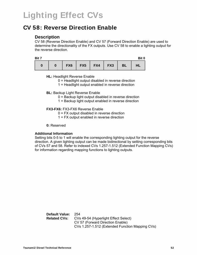
CV 58: Reverse Direction Enable Description CV 58 (Reverse Direction Enable) and CV 57 (Forward Direction Enable) are used to determine the directionality of the FX outputs. Use CV 58 to enable a lighting output for the reverse direction. Bit 7 Bit 0
0 0 FX6 FX5 FX4 FX3 BL HL
HL: Headlight Reverse Enable
0 = Headlight output disabled in reverse direction 1 = Headlight output enabled in reverse direction
BL: Backup Light Reverse Enable 0 = Backup light output disabled in reverse direction 1 = Backup light output enabled in reverse direction
FX3-FX6: FX3-FX6 Reverse Enable 0 = FX output disabled in reverse direction 1 = FX output enabled in reverse direction
0: Reserved
Additional Information Setting bits 0-5 to 1 will enable the corresponding lighting output for the reverse direction. A given lighting output can be made bidirectional by setting corresponding bits of CVs 57 and 58. Refer to indexed CVs 1.257-1.512 (Extended Function Mapping CVs) for information regarding mapping functions to lighting outputs.
Default Value: 254 Related CVs: CVs 49-54 (Hyperlight Effect Select)
CV 57 (Forward Direction Enable) CVs 1.257-1.512 (Extended Function Mapping CVs)
Lighting Effect CVs
Tsunami2 Diesel Technical Reference 53
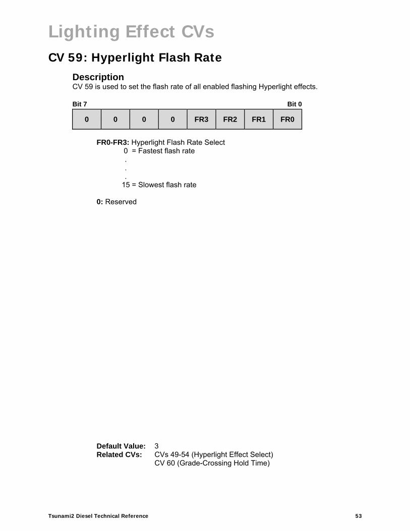
CV 59: Hyperlight Flash Rate Description CV 59 is used to set the flash rate of all enabled flashing Hyperlight effects. Bit 7 Bit 0
0 0 0 0 FR3 FR2 FR1 FR0
FR0-FR3: Hyperlight Flash Rate Select
0 = Fastest flash rate. . .
15 = Slowest flash rate
0: Reserved
Default Value: 3 Related CVs: CVs 49-54 (Hyperlight Effect Select)
CV 60 (Grade-Crossing Hold Time)

Lighting Effect CVs
Tsunami2 Diesel Technical Reference 54
CV 60: Grade-Crossing Hold Time Description CV 60 is used to set the duration of the crossing hold countdown from 0 to 15 seconds. Bit 7 Bit 0
0 0 0 0 HT3 HT2 HT1 HT0
HT0-HT3: Hold Time Select
0 = 0 seconds . . .
15 = 15 seconds
0: Reserved
Additional Information The countdown will occur when the long airhorn function (F2 by default) or grade crossing horn is turned on to activate Grade-Crossing Logic. Setting bit 6 to 1 of CVs 49-54 (Hyperlight Effect Select) will enable Grade-Crossing Logic.
Default Value: 4 Related CVs: CVs 49-54 (Hyperlight Effect Select)
CV 57 (Forward Direction Enable) CV 58 (Reverse Direction Enable) CV 59 (Hyperlight Flash Rate)

Lighting Effect CVs
Tsunami2 Diesel Technical Reference 55
CV 61: Brightness Register 1 Description CV 61 is used to adjust the brightness level of lighting outputs set to the on/off brightness 1 effect. Bit 7 Bit 0
D7 D6 D5 D4 D3 D2 D1 D0
D0-D7: Brightness Level 1
0 = 0% Brightness . . .
255 = 100% Brightness
Default Value: 153 Related CVs: CVs 49-54 (Hyperlight Effect Select)
CV 63 (Dimmer Level)

Lighting Effect CVs
Tsunami2 Diesel Technical Reference 56
CV 62: Brightness Register 2 Description CV 62 is used to adjust the brightness level of lighting outputs set to the on/off brightness 2 effect. Bit 7 Bit 0
D7 D6 D5 D4 D3 D2 D1 D0
D0-D7: Brightness Level 2
0 = 0% Brightness . . .
255 = 100% Brightness
Default Value: 153 Related CVs: CVs 49-54 (Hyperlight Effect Select)
CV 63 (Dimmer Level)
Lighting Effect CVs
Tsunami2 Diesel Technical Reference 57
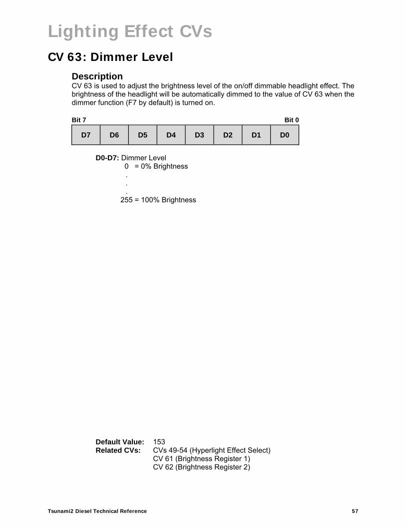
CV 63: Dimmer Level Description CV 63 is used to adjust the brightness level of the on/off dimmable headlight effect. The brightness of the headlight will be automatically dimmed to the value of CV 63 when the dimmer function (F7 by default) is turned on. Bit 7 Bit 0
D7 D6 D5 D4 D3 D2 D1 D0
D0-D7: Dimmer Level
0 = 0% Brightness . . .
255 = 100% Brightness
Default Value: 153 Related CVs: CVs 49-54 (Hyperlight Effect Select)
CV 61 (Brightness Register 1) CV 62 (Brightness Register 2)
Lighting Effect CVs
Tsunami2 Diesel Technical Reference 58
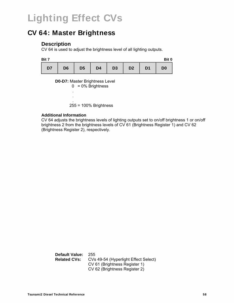
CV 64: Master Brightness Description CV 64 is used to adjust the brightness level of all lighting outputs. Bit 7 Bit 0
D7 D6 D5 D4 D3 D2 D1 D0
D0-D7: Master Brightness Level
0 = 0% Brightness . . .
255 = 100% Brightness Additional Information CV 64 adjusts the brightness levels of lighting outputs set to on/off brightness 1 or on/off brightness 2 from the brightness levels of CV 61 (Brightness Register 1) and CV 62 (Brightness Register 2), respectively.
Default Value: 255 Related CVs: CVs 49-54 (Hyperlight Effect Select)
CV 61 (Brightness Register 1) CV 62 (Brightness Register 2)

Speed Table CVs
Tsunami2 Diesel Technical Reference 59
Speed Table CVs
CV 66: Forward Motor Trim Description CV 66 is used to determine the scaling factor that will increase or decrease the forward drive voltage.
Bit 7 Bit 0
D7 D6 D5 D4 D3 D2 D1 D0
D0-D7: Forward Trim Scalar
0 = Disabled 1 = Voltage × 0.008. . .
127 = Voltage × 0.91 128 = Disabled 129 = Voltage × 1.09
.
.
.
255 = Voltage × 1.91
Additional Information Values from 0 to 255 may be entered into CV 66 to determine the scaling factor for the forward drive voltage. Entering a value of 0 or 128 will disable the forward trim scalar. Entering a value from 1 to 127 will multiply the forward drive voltage by 0.008-0.91. Entering a value from 129 to 255 will multiply the forward drive voltage by 1.09-1.91. Note: Bit 4 (STE) of CV 29 (Configuration Data 1) must be set to 1 to enable the forward trim scaling factor in CV 66. Also, CV 25 cannot be set to either 1 or 0.
Default Value: 128 Related CVs: CV 25 (Speed Table Enable)
CV 29 (Configuration Data 1) CVs 67-94 (Custom Speed Table)CV 95 (Reverse Motor Trim)
Speed Table CVs
Tsunami2 Diesel Technical Reference 60
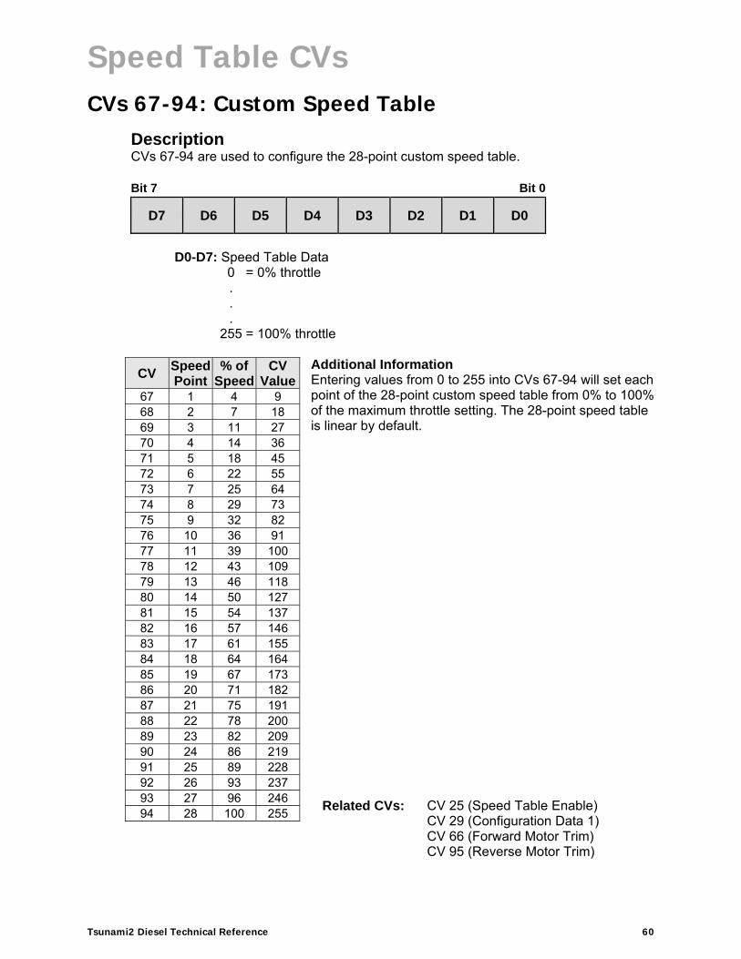
CVs 67-94: Custom Speed Table Description CVs 67-94 are used to configure the 28-point custom speed table. Bit 7 Bit 0
D7 D6 D5 D4 D3 D2 D1 D0
D0-D7: Speed Table Data
0 = 0% throttle . . .
255 = 100% throttle
Additional Information Entering values from 0 to 255 into CVs 67-94 will set each point of the 28-point custom speed table from 0% to 100% of the maximum throttle setting. The 28-point speed table is linear by default.
CV Speed Point
% of Speed
CV Value
67 1 4 9 68 2 7 18 69 3 11 27 70 4 14 36 71 5 18 45 72 6 22 55 73 7 25 64 74 8 29 73 75 9 32 82 76 10 36 91 77 11 39 100 78 12 43 109 79 13 46 118 80 14 50 127 81 15 54 137 82 16 57 146 83 17 61 155 84 18 64 164 85 19 67 173 86 20 71 182 87 21 75 191 88 22 78 200 89 23 82 209 90 24 86 219 91 25 89 228 92 26 93 237 93 27 96 246 94 28 100 255
Related CVs: CV 25 (Speed Table Enable)CV 29 (Configuration Data 1)CV 66 (Forward Motor Trim) CV 95 (Reverse Motor Trim)

Speed Table CVs
Tsunami2 Diesel Technical Reference 61
CV 95: Reverse Motor Trim Description CV 95 is used to determine the scaling factor that will increase or decrease the reverse drive voltage.
Bit 7 Bit 0
D7 D6 D5 D4 D3 D2 D1 D0
D0-D7: Reverse Trim Scalar
0 = Disabled 1 = Voltage ÷ 0.008. . .
127 = Voltage ÷ 0.99 128 = Disabled 129 = Voltage × 1.09
.
.
.
255 = Voltage × 1.99
Additional Information Values from 0 to 255 may be entered into CV 95 to determine the scaling factor for the reverse drive voltage. Entering a value of 0 or 128 will disable the reverse trim scalar. Entering a value from 1 to 127 will decrease the reverse drive voltage by 0.008-0.99. Entering a value from 129 to 255 will increase the reverse drive voltage by 1.09-1.99. Note: Bit 4 (STE) of CV 29 (Configuration Data 1) must be set to 1 to enable the reverse trim scaling factor in CV 95. Also, CV 25 cannot be set to either 1 or 0.
Default Value: 128 Related CVs: CV 25 (Speed Table Enable)
CV 29 (Configuration Data 1) CVs 67-94 (Custom Speed Table)CV 66 (Forward Motor Trim)

User Information CVs
Tsunami2 Diesel Technical Reference 62
User Information CVs
CV 105: User Identifier 1 Description CV 105 indicates the software’s major revision code and provides storage for user-supplied data. This CV has no other effect on decoder operation. Bit 7 Bit 0
D7 D6 D5 D4 D3 D2 D1 D0
D0-D7: User Identifier Data
Additional Information This CV may be programmed with any value from 0 to 255. CV 105 will return to the software’s major revision code when the decoder is reset to factory settings.
Default Value: Varies by software revisionRelated CVs: CV 106 (User Identifier 2)

User Information CVs
Tsunami2 Diesel Technical Reference 63
CV 106: User Identifier 2 Description CV 106 indicates the software’s minor revision code. This CV may be used to provide storage for user-supplied data. This CV has no other effect on decoder operation. Bit 7 Bit 0
D7 D6 D5 D4 D3 D2 D1 D0
D0-D7: User Identifier Data
Additional Information This CV may be programmed with any value from 0 to 255. CV 106 will return to the software’s minor revision code when the decoder is reset to factory settings.
Default Value: Varies by software revisionRelated CVs: CV 105 (User Identifier 1)

Sound Control CVs
Tsunami2 Diesel Technical Reference 64
Sound Control CVs
CV 112: Sound Configuration 1 Description CV 112 is used to enable the low-pressure alarm bell and the emergency stop idle sequence. Bit 7 Bit 0
0 0 0 0 0 0 ABE ESTP
ESTP: Emergency Stop Idle Enable
0 = Emergency stop engine shutdown 1 = Emergency stop engine idle
ABE: Alarm Bell Enable
0 = Low-pressure alarm bell disabled 1 = Low-pressure alarm bell enabled
0: Reserved
Default Value: 3 Related CVs: CVs 112-208 (Sound Control CVs)

Sound Control CVs
Tsunami2 Diesel Technical Reference 65
CV 113: Quiet Mode Time-Out Period Description CV 113 is used to set the quiet mode time-out period. When the throttle is set to zero and all functions are off all sound effects will automatically deactivate after the quiet mode time-out period elapses. Setting CV 113 to a non-zero value will adjust the time-out period and allow sound effects to be reactivated only when the decoder is addressed.
Bit 7 Bit 0
QM7 QM6 QM5 QM4 QM3 QM2 QM1 QM0
QM0-QM7: Quiet Mode Time-Out Period
0 = Disabled 1 = 1 second . . .
255 = 255 seconds
Additional Information Entering a value from 1 to 255 into CV 113 will adjust the quiet mode time-out period from 1 second to 255 seconds. Entering a value of 0 into CV 113 will disable the quiet mode time-out period.
Default Value: 0 Related CVs: CVs 112-208 (Sound Control CVs)

Sound Control CVs
Tsunami2 Diesel Technical Reference 66
CV 114: Engine Exhaust Control Description CV 114 is used to adjust the auto-notching sensitivity level, enable engine interlock, enable auto-start, and select from four dynamic braking modes. Decimal values for bits 0-3 (AN0-AN3) and binary values for bits 4-7 (LOCK, ASTRT, and DB0-DB1) are defined as follows: Bit 7 Bit 0
DB1 DB0 ASTRT LOCK AN3 AN2 AN1 AN0
AN0-AN3: Auto-Notching Sensitivity
0 = Auto-notching disabled1 = 1 speed step/notch . . .
15 = 15 speed steps/notch LOCK: Engine Interlock Enable
0 = Engine interlock disabled 1 = Engine interlock enabled
ASTRT: Auto-Start Enable 0 = Auto-start disabled 1 = Auto-start enabled
DB0-DB1: Dynamic Braking Mode Select
00 = Normal operation (default)01 = Idle speed (notch 1) 10 = Half-speed (notch 4) 11 = Full speed (notch 8)
Additional Information Entering values from 1 to 15 into bits 0-3 (AN0-AN3) will:
Enable auto-notching
Designate the number of speed steps contained within each engine RPM notch
Allow the prime mover to start when the throttle is increased from zero unless bit 0 in CV 112 is set to 1.
Values from 1 to 15 specify the number of speed steps within each engine RPM notch from 1 to 15. For example, when CV 114 is set to 15 and 128 speed-step mode is in use, increasing the throttle from zero to speed-step 91 will heighten the engine RPM from idle (notch 1) to notch 8. Setting bits 0-3 to 0 will disable auto-notching and enable manual notching.

Sound Control CVs
Tsunami2 Diesel Technical Reference 67
Setting bit 4 (LOCK) to 1 will enable engine interlock. When engine interlock is enabled, the prime mover must be started prior to setting the locomotive into motion, and cannot be turned off during movement; locomotive speed must be zero for the prime mover to be started and shut off, respectively. Setting bit 5 (ASTRT) to 1 will enable auto-start. Auto-start allows the prime mover to be started automatically when the decoder receives track power. For DCC operation, the prime mover will not start upon receiving track power when bit 5 is set to 0 and auto-start is disabled. For analog mode (DC) operation, the prime mover will start when the decoder receives track power regardless of bit 5, i.e., auto-start cannot be disabled with CV 114 in analog mode. Bits 6-7 (DB0-DB1) are used to select from four dynamic braking modes. When bits 6-7 are equal to a non-zero value, turning on the dynamic brake function (F4 by default) will set the engine RPM sound effect from its current state to a designated notch setting. Decimal values used for selecting dynamic braking modes are provided below and must be added to the value of CV 114:
0 = Normal: Dynamic brake application only (default) 64 = Idle speed: Dynamic brake sets RPM to notch 1
128 = Half-speed: Dynamic brake sets RPM to notch 4 192 = Full speed: Dynamic brake sets RPM to notch 8
Default Value: 39 Related CVs: CVs 112-208 (Sound Control CVs)
CVs 2.503-2.512 (DDE Control CVs)
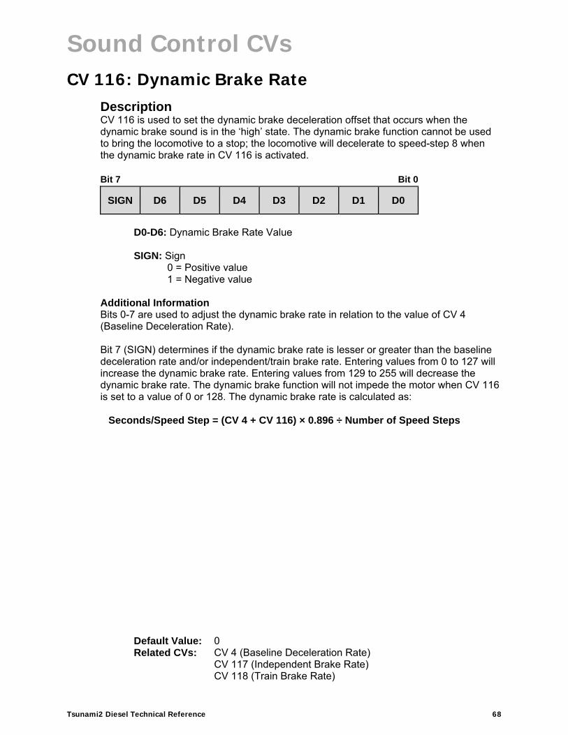
Sound Control CVs
Tsunami2 Diesel Technical Reference 68
CV 116: Dynamic Brake Rate Description CV 116 is used to set the dynamic brake deceleration offset that occurs when the dynamic brake sound is in the ‘high’ state. The dynamic brake function cannot be used to bring the locomotive to a stop; the locomotive will decelerate to speed-step 8 when the dynamic brake rate in CV 116 is activated. Bit 7 Bit 0
SIGN D6 D5 D4 D3 D2 D1 D0
D0-D6: Dynamic Brake Rate Value
SIGN: Sign
0 = Positive value 1 = Negative value
Additional Information Bits 0-7 are used to adjust the dynamic brake rate in relation to the value of CV 4 (Baseline Deceleration Rate). Bit 7 (SIGN) determines if the dynamic brake rate is lesser or greater than the baseline deceleration rate and/or independent/train brake rate. Entering values from 0 to 127 will increase the dynamic brake rate. Entering values from 129 to 255 will decrease the dynamic brake rate. The dynamic brake function will not impede the motor when CV 116 is set to a value of 0 or 128. The dynamic brake rate is calculated as:
Seconds/Speed Step = (CV 4 + CV 116) × 0.896 ÷ Number of Speed Steps
Default Value: 0 Related CVs: CV 4 (Baseline Deceleration Rate)
CV 117 (Independent Brake Rate)CV 118 (Train Brake Rate)

Sound Control CVs
Tsunami2 Diesel Technical Reference 69
CV 117: Independent Brake Rate Description CV 117 configures the motive effect of the independent brake. When the independent brake rate is set to any value other than 0 or 128, the locomotive comes to a stop when the independent brake is on. The independent brake is on when the train brake select function is off and the brake function is on. The rate at which the locomotive decelerates is equal to the combined rate from CVs 4 and 24 plus the independent brake rate value.
Bit 7 Bit 0
SIGN D6 D5 D4 D3 D2 D1 D0
D0-D6: Independent Brake Rate Value
SIGN: Sign
0 = Positive value 1 = Negative value
Additional Information Bits 0-7 are used to adjust the independent brake rate in relation to the value of CV 4. Bit 7 (SIGN) determines if the independent brake rate is lesser or greater than the baseline deceleration rate. Entering values from 0 to 127 will increase the independent brake rate from the baseline deceleration rate. Entering values from 129 to 255 will decrease the independent brake rate from the baseline deceleration rate. The independent brake function will not impede the motor when CV 117 is set to a value of 0 or 128.
Seconds/Speed Step = (CV 4 + CV 117) × 0.896 ÷ Number of Speed Steps
Default Value: 0 Related CVs: CV 4 (Baseline Deceleration Rate)
CV 116 (Dynamic Brake Rate) CV 118 (Train Brake Rate)

Sound Control CVs
Tsunami2 Diesel Technical Reference 70
CV 118: Train Brake Rate Description CV 118 configures the motive effect of the train brake. When the train brake rate is set to any value other than 0 or 128, the locomotive comes to a stop when the train brake is on. The train brake is on when the train brake select function is on and the brake function is on. The rate at which the locomotive decelerates is equal to the combined rate from CVs 4 and 24 plus the independent brake rate value.
Bit 7 Bit 0
SIGN D6 D5 D4 D3 D2 D1 D0
D0-D6: Train Brake Rate Value
SIGN: Sign
0 = Positive value 1 = Negative value
Additional Information Bits 0-7 are used to adjust the train brake rate in relation to the value of CV 4 (Baseline Deceleration Rate). Bit 7 (SIGN) determines if the train brake rate is added or subtracted to the baseline deceleration rate in CV 4. Entering values from 0 to 127 in CV 118 will increase the train brake rate from the baseline deceleration rate in CV 4. Entering values from 129 to 255 into CV 118 will decrease the train brake rate from the baseline deceleration rate in CV 4. The train brake function will not stop the locomotive when CV 118 is set to a value of 0 or 128.
Seconds/Speed Step = (CV 4 + CV 118) × 0.896 ÷ Number of Speed Steps
Default Value: 0 Related CVs: CV 4 (Baseline Deceleration Rate)
CV 117 (Independent Brake Rate)
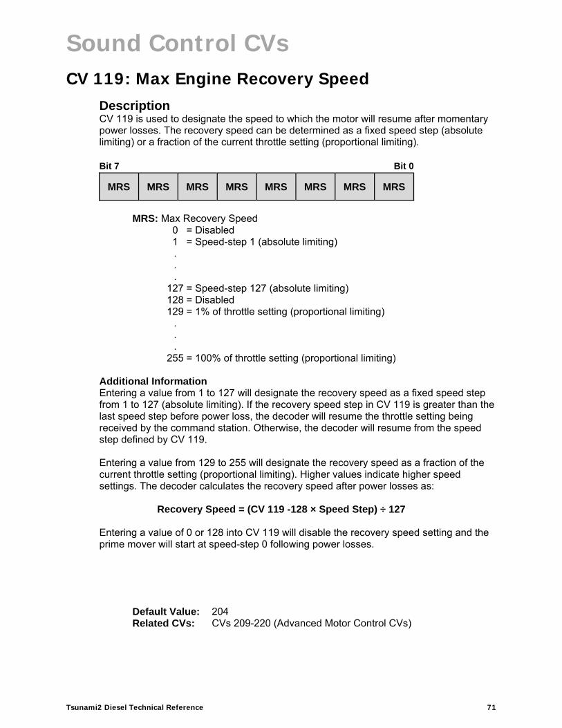
Sound Control CVs
Tsunami2 Diesel Technical Reference 71
CV 119: Max Engine Recovery Speed Description CV 119 is used to designate the speed to which the motor will resume after momentary power losses. The recovery speed can be determined as a fixed speed step (absolute limiting) or a fraction of the current throttle setting (proportional limiting). Bit 7 Bit 0
MRS MRS MRS MRS MRS MRS MRS MRS
MRS: Max Recovery Speed
0 = Disabled 1 = Speed-step 1 (absolute limiting) . . .
127 = Speed-step 127 (absolute limiting) 128 = Disabled 129 = 1% of throttle setting (proportional limiting)
.
.
.
255 = 100% of throttle setting (proportional limiting)
Additional Information Entering a value from 1 to 127 will designate the recovery speed as a fixed speed step from 1 to 127 (absolute limiting). If the recovery speed step in CV 119 is greater than the last speed step before power loss, the decoder will resume the throttle setting being received by the command station. Otherwise, the decoder will resume from the speed step defined by CV 119. Entering a value from 129 to 255 will designate the recovery speed as a fraction of the current throttle setting (proportional limiting). Higher values indicate higher speed settings. The decoder calculates the recovery speed after power losses as:
Recovery Speed = (CV 119 -128 × Speed Step) ÷ 127 Entering a value of 0 or 128 into CV 119 will disable the recovery speed setting and the prime mover will start at speed-step 0 following power losses.
Default Value: 204 Related CVs: CVs 209-220 (Advanced Motor Control CVs)
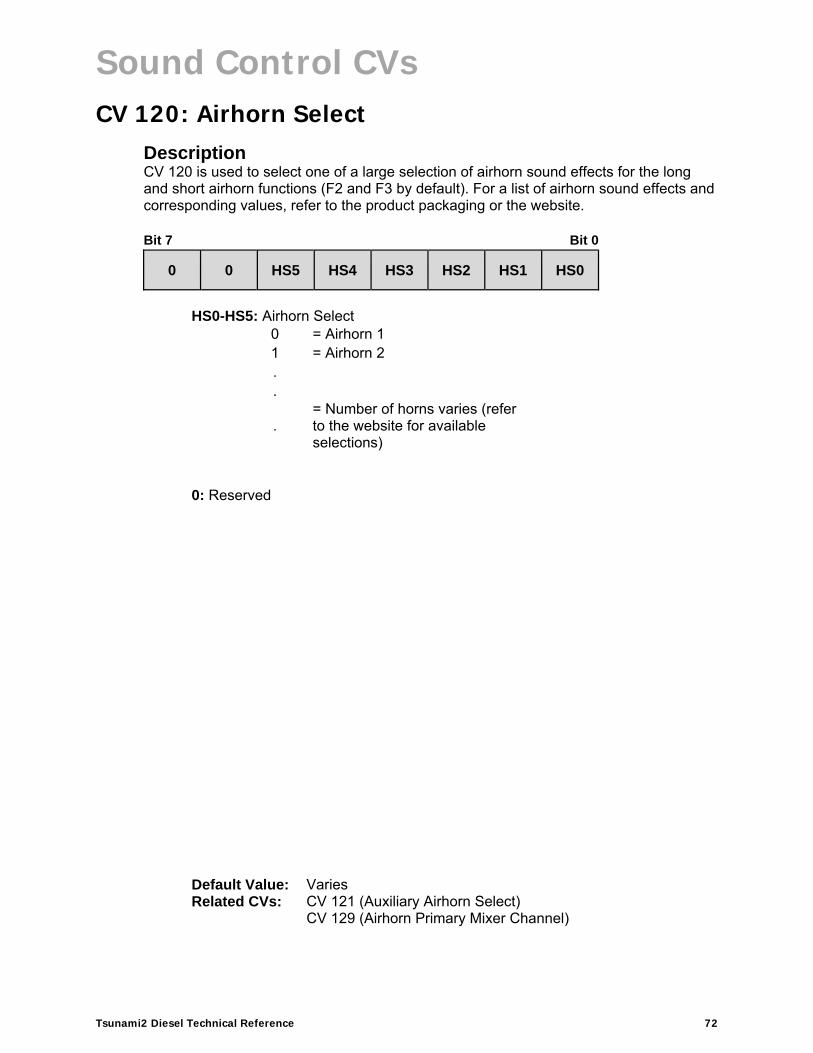
Sound Control CVs
Tsunami2 Diesel Technical Reference 72
CV 120: Airhorn Select Description CV 120 is used to select one of a large selection of airhorn sound effects for the long and short airhorn functions (F2 and F3 by default). For a list of airhorn sound effects and corresponding values, refer to the product packaging or the website. Bit 7 Bit 0
0 0 HS5 HS4 HS3 HS2 HS1 HS0
HS0-HS5: Airhorn Select
0 = Airhorn 1 1 = Airhorn 2 . .
. = Number of horns varies (refer to the website for available selections)
0: Reserved
Default Value: Varies Related CVs: CV 121 (Auxiliary Airhorn Select)
CV 129 (Airhorn Primary Mixer Channel)

Sound Control CVs
Tsunami2 Diesel Technical Reference 73
CV 121: Alternate Airhorn Select Description CV 121 is used for selecting one of a large number of alternate airhorn sound effects. For a list of airhorn sound effects and corresponding values, refer to the product packaging or the website. Bit 7 Bit 0
0 0 AH5 AH4 AH3 AH2 AH1 AH0
AH0-AH5: Alternate Airhorn Select
0 = Alternate airhorn disabled 1 = Replaces Short Airhorn with Alternate airhorn 1 . . .
= Number of horns varies (refer to the website for available selections) 0: Reserved
More Information Bits 0-5 (AH0-AH5) are used to select the alternate airhorn sound effect. When the alternate airhorn is enabled, the short airhorn function is disabled. When the alternate airhorn is enabled and the short airhorn function is turned on, the long airhorn function is used to activate the alternate airhorn sound effect.
Default Value: 0 Related CVs: CV 120 (Airhorn Select)
CV 129 (Airhorn Primary Mixer Channel)

Sound Control CVs
Tsunami2 Diesel Technical Reference 74
CV 122: Bell Select Description CV 122 is used for configuring the bell sound effect and ring-rate, and for enabling the selected bell to ring during the crossing-timer countdown when Grade-Crossing Logic is activated. Refer to CVs 49-54 (Hyperlight Effect Select) for more information regarding Grade-Crossing Logic. The number of available bells and bell types will vary with each decoder version. For a list of bell sound effects and corresponding values, refer to the website. Bit 7 Bit 0
BXING 0 BS5 BS4 BS3 BS2 BS1 BS0
BS0-BS5: Bell Select
BXING: Grade-Crossing Bell Enable
0 = Disabled 1 = Enabled
0: Reserved
Default Value: Varies Related CVs: CVs 49-54 (Hyperlight Effect Select)
CV 60 (Grade-Crossing Hold Time) CV 130 (Bell Primary Mixer Channel)

Sound Control CVs
Tsunami2 Diesel Technical Reference 75
CV 123: Prime Mover Select Description CV 123 is used to select one of up to nine prime mover sound effects (varies by version). Bit 7 Bit 0
0 0 0 0 PM3 PM2 PM1 PM0
PM0-PM3: Prime Mover Select
0 = Prime mover 1 1 = Prime mover 2 2 = Prime mover 3 3 = Prime mover 4 4 = Prime mover 5 5 = Prime mover 6 6 = Prime mover 7 7 = Prime mover 8 8 = Prime mover 9
0: Reserved
Default Value: Varies Related CVs: CV 131 (Prime Mover Primary Mixer Channel)

Sound Control CVs
Tsunami2 Diesel Technical Reference 76
CV 124: Air Compressor Select Description CV 124 is used to select an air compressor sound effect. For a list of air compressors and corresponding values, refer to the website. Bit 7 Bit 0
0 0 0 0 0 0 CS1 CS0
CS0-CS1: Air Compressor Select
0 = Air Compressor 1 1 = Air Compressor 2 2 = Air Compressor 3 3 = Air Compressor 4
0: Reserved
Additional Information The selected air compressor sound effect cycles on and off continuously when the prime mover is on.
Default Value: Varies Related CVs: CV 132 (Air Compressor Primary Mixer Channel)

Sound Control CVs
Tsunami2 Diesel Technical Reference 77
CV 126: Coupler Select Description CV 126 is used to select the coupler sound effect that will be activated by the couple/uncouple functions (F13 by default). Bit 7 Bit 0
CRP 0 0 0 0 0 CPL1 CPL0
CPL0-CPL1: Coupler Select
0 = Medium coupler1 = Heavy coupler 2 = Link-and-pin
CRP: Uncouple Function Polarity
0 = Uncouple when function is turned on 1 = Uncouple when function is turned off
0: Reserved
Additional Information By default, bit 7 (CRP) is set to 1 and the couple and uncouple functions are mapped to F13; turning on F13 will activate the coupling sound effect and turning off F13 will activate the uncoupling sound effect. When bit 7 is set to 0 and the couple and uncouple functions are mapped to the same function key, turning on the function key will activate the coupling sound effect and turning off the function key will have no effect. When bit 7 is set to 0 and the couple and uncouple functions are mapped to separate function keys, turning on the couple function key will activate the coupling sound effect and turning on the uncouple function key will activate the uncoupling sound effect. Turning off the couple and uncouple function keys will have no effect. The link-and-pin coupler does not include the uncouple or glad hand release.
Default Value: 128 Related CVs: CV 137 (Coupler Primary Mixer Channel)

Sound Control CVs
Tsunami2 Diesel Technical Reference 78
CV 128: Master Volume Description CV 128 is used to set the volume level of all sound channels. Bit 7 Bit 0
VOL7 VOL6 VOL5 VOL4 VOL3 VOL2 VOL1 VOL0
VOL0-VOL7: Master Volume
0 = 0% volume . . .
255 = 100% volume
Default Value: 192 Related CVs: CVs 129-160 (Primary Mixer Volume Levels)
CVs 2.289-2.320 (Alternate Mixer Volume Levels)

Sound Control CVs
Tsunami2 Diesel Technical Reference 79
CVs 129-160: Primary Mixer Volume Levels Description CVs 129-160 are used in conjunction with CV 128 (Master Volume) to set the volume level of each sound effect. Bit 7 Bit 0
MIX7 MIX6 MIX5 MIX4 MIX3 MIX2 MIX1 MIX0
MIX0-MIX7: Primary Mixer Channel Volume
0 = 0% of master volume . . .
255 = 100% of master volume Additional Information Setting CVs 129-160 to a value from 0 to 255 will adjust the corresponding sound effect’s volume level from the master volume level in CV 128. For example, if CV 128 is set to 50% volume (CV 128 = 128), setting CV 129 to a value of 128 would adjust the airhorn volume level to 50% of the master volume level, i.e., the airhorn volume would be set to 25% of the maximum volume level.
Mixer channel CVs with corresponding default values are listed on the following page.
Related CVs: CV 128 (Master Volume)

Sound Control CVs
Tsunami2 Diesel Technical Reference 80
CVs 129-160: Primary Mixer Volume Levels
CV Sound Effect Default Value
129 Airhorn 225
130 Bell 85
131 Prime Mover 150
132 Air Compressor 100
133 Dynamic Brake 125
134 Radiator Fans 75
135 Alarm Bell 60
136 Reserved 0
137 Coupler 128
138 Train Brake Apply/Release 128
139 Independent Brake Apply 100
140 Independent Brake Release 70
141 Reserved 0
142 Reserved 0
143 Poppet Valve 60
144 Steam Generator 50
145 Cab Doors 128
146 Reserved 0
147 Relay Clicks 128
148 E-Brake App. 70
149 Glad Hand Release 150
150 All Aboard/Coach Doors 192
151 Reserved 0
152 Reserved 0
153 Clickety-Clack 150
154 Sander Valve 10
155 Fuel Loading 50
156 Air Conditioner 20
157 Wrenches 50
158 Pneumatic Oilers 40
159 Toilet Flush 20
160 Cab Chatter 60
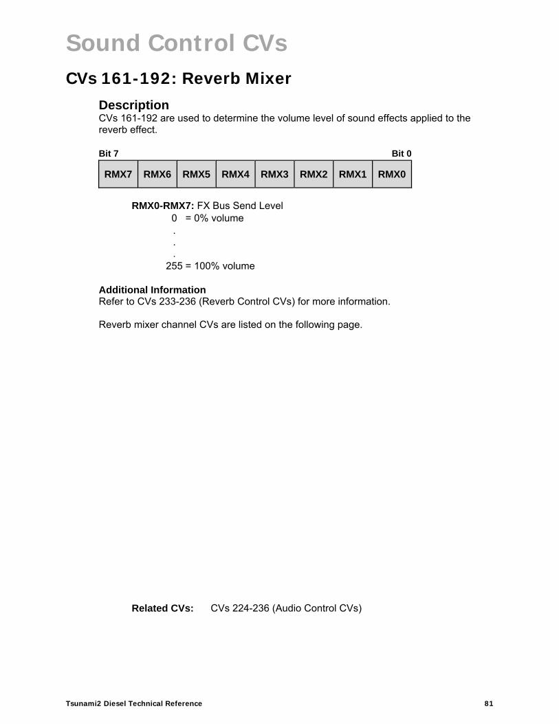
Sound Control CVs
Tsunami2 Diesel Technical Reference 81
CVs 161-192: Reverb Mixer Description CVs 161-192 are used to determine the volume level of sound effects applied to the reverb effect. Bit 7 Bit 0
RMX7 RMX6 RMX5 RMX4 RMX3 RMX2 RMX1 RMX0
RMX0-RMX7: FX Bus Send Level
0 = 0% volume . . .
255 = 100% volume
Additional Information Refer to CVs 233-236 (Reverb Control CVs) for more information. Reverb mixer channel CVs are listed on the following page.
Related CVs: CVs 224-236 (Audio Control CVs)

Sound Control CVs
Tsunami2 Diesel Technical Reference 82
CVs 161-192: Reverb Mixer
CV Sound Effect Default Value 161 Airhorn 96 162 Bell 0 163 Prime Mover 0 164 Air Compressor 0 165 Dynamic Brake 0 166 Radiator Fans 0 167 Alarm Bell 0 168 Reserved 0 169 Coupler 0 170 Train Brake Apply/Release 0 171 Independent Brake Apply 0 172 Independent Brake Release 0 173 Reserved 0 174 Reserved 0 175 Poppet Valve 0 176 Steam Generator 0 177 Cab Doors 0 178 Reserved 0 179 Relay Clicks 0 180 E-Brake App. 0 181 Glad Hand Release 0 182 All Aboard/Coach Doors 0 183 Reserved 0 184 Reserved 0 185 Clickety-Clack 0 186 Sander Valve 0 187 Fuel Loading 0 188 Air Conditioner 0 189 Wrenches 0 190 Pneumatic Oilers 0 191 Toilet Flush 0 192 Cab Chatter 0
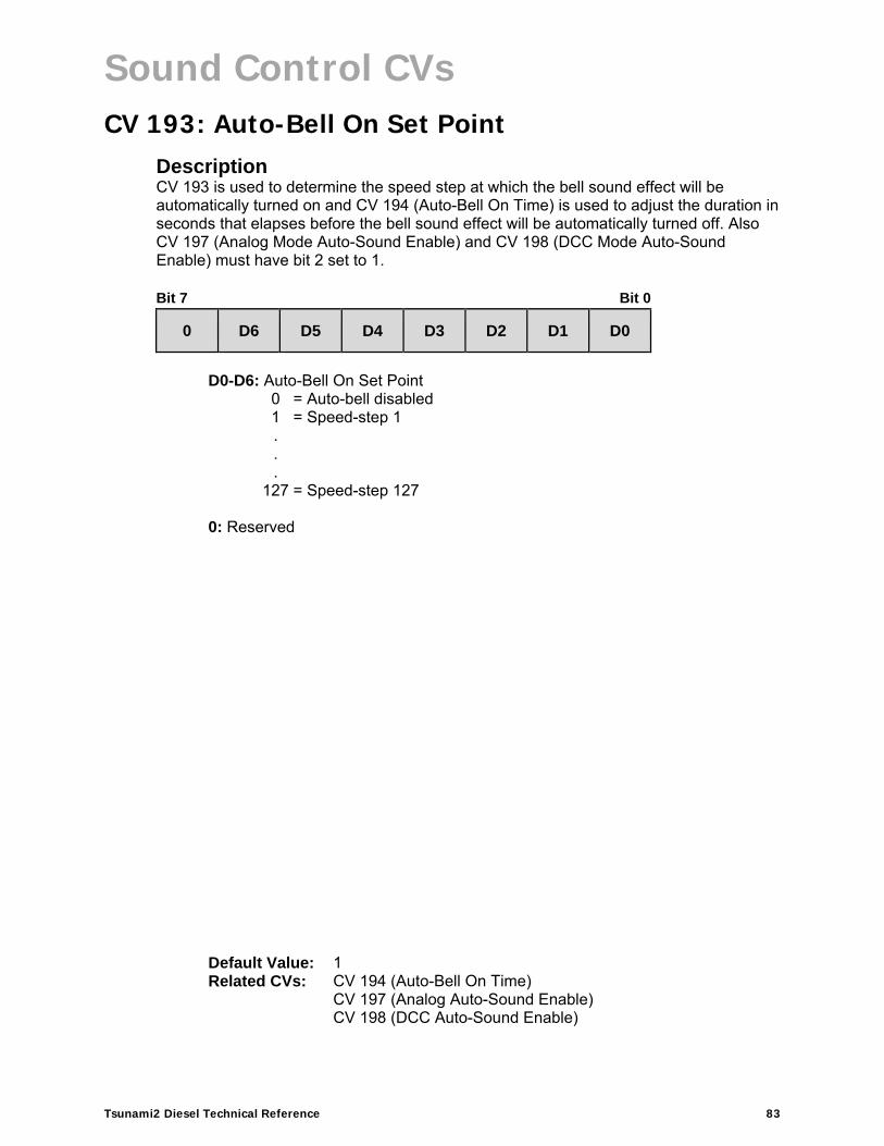
Sound Control CVs
Tsunami2 Diesel Technical Reference 83
CV 193: Auto-Bell On Set Point Description CV 193 is used to determine the speed step at which the bell sound effect will be automatically turned on and CV 194 (Auto-Bell On Time) is used to adjust the duration in seconds that elapses before the bell sound effect will be automatically turned off. Also CV 197 (Analog Mode Auto-Sound Enable) and CV 198 (DCC Mode Auto-Sound Enable) must have bit 2 set to 1. Bit 7 Bit 0
0 D6 D5 D4 D3 D2 D1 D0
D0-D6: Auto-Bell On Set Point
0 = Auto-bell disabled1 = Speed-step 1 . . .
127 = Speed-step 127 0: Reserved
Default Value: 1 Related CVs: CV 194 (Auto-Bell On Time)
CV 197 (Analog Auto-Sound Enable)CV 198 (DCC Auto-Sound Enable)

Sound Control CVs
Tsunami2 Diesel Technical Reference 84
CV 194: Auto-Bell On Time Description CV 194 is used to set the duration in seconds that elapses from the time the bell sound effect is automatically turned on to the time it is turned off. CV 193 (Auto-Bell On Set Point) is used to determine the speed step at which the bell sound effect is turned on. Also CV 197 (Analog Mode Auto-Sound Enable) and CV 198 (DCC Mode Auto-Sound Enable) must have bit 2 set to 1. Bit 7 Bit 0
D7 D6 D5 D4 D3 D2 D1 D0
D0-D7: Auto-Bell On Time
0 = Auto-bell disabled1 = 1 second . . .
255 = 255 seconds
Default Value: 15 Related CVs: CV 193 (Auto-Bell On Set Point)
CV 197 (Analog Mode Auto-Sound Enable) CV 198 (DCC Auto-Sound Enable)

Sound Control CVs
Tsunami2 Diesel Technical Reference 85
CV 195: Coach Door Count Description CV 195 is used to set the maximum number of coach door slams that will occur when the all aboard/coach doors function (F23 by default) is turned on. From the range defined by the value of CV 195, a random number of coach door slams will be issued when the all aboard/coach doors function is turned on. Bit 7 Bit 0
0 0 0 0 CD3 CD2 CD1 CD0
CD0-CD3: Coach Doors
0 = Disabled1 = 1 slam . . .
15 = 15 slams 0: Reserved
Default Value: 5 Related CVs: CV 150 (All Aboard/Coach Doors Primary Mixer Channel)

Sound Control CVs
Tsunami2 Diesel Technical Reference 86
CV 196: Brake Sensitivity Description CV 196 is used to adjust the automatic brake activation point. The value of CV 196 sets the rate of throttle decrease that will activate the brake sound effect. Bit 7 Bit 0
D7 D6 D5 D4 D3 D2 D1 D0
D0-D7: Brake Sensitivity
0 = 0.10 speed steps/second.
.
.
.
255 = 25.5 speed steps/second Additional Information The value of CV 196 indicates the rate of throttle decrease required for the brake sound effect to be automatically activated and is calculated as:
CV Value = Speed Steps/Second ÷ 10
Default Value: 3 Related CVs: CV 4 (Baseline Deceleration Rate)
CV 117 (Independent Brake Rate) CV 139 (Independent Brake Apply Primary Mixer Channel)CV 140 (Train Brake Apply Primary Mixer Channel)

Sound Control CVs
Tsunami2 Diesel Technical Reference 87
CV 197: Analog Mode Auto-Sound Enable Description CV 197 is used to enable automatic sound effects for analog mode operation. Bit 7 Bit 0
0 0 0 0 0 ABK ABL 0
ABL: Auto-Bell Enable
0 = Disabled 1 = Enabled
ABK: Auto-Brake Enable
0 = Disabled 1 = Enabled
0: Reserved
Default Value: 0 Related CVs: CV 12 (Alternate Power Source)
CV 29 (Configuration Data 1)

Sound Control CVs
Tsunami2 Diesel Technical Reference 88
CV 198: DCC Mode Auto-Sound Enable Description CV 198 is used to enable automatic sound effects in DCC mode. Bit 7 Bit 0
0 0 0 0 0 ABK ABL 0
ABL: Auto-Bell Enable
0 = Disabled 1 = Enabled
ABK: Auto-Brake Enable
0 = Disabled 1 = Enabled
0: Reserved
Default Value: 0 Related CVs: CV 12 (Alternate Power Source)
CV 29 (Configuration Data 1)

Sound Control CVs
Tsunami2 Diesel Technical Reference 89
CV 200: Poppet Valve Release Rate Description CV 200 is used to adjust the duration that occurs between each subsequent “pop!” of the automatic poppet valve sound effect. Bit 7 Bit 0
D7 D6 D5 D4 D3 D2 D1 D0
D0-D7: Poppet Valve Release Rate
0 = Poppet valve disabled1 = Fastest release rate . . .
255 = Slowest release rate
Default Value: 25 Related CVs: CV 143 (Poppet Valve Primary Mixer Channel)

Sound Control CVs
Tsunami2 Diesel Technical Reference 90
CVs 201-208: Fireman Ed Probability CVs Description CVs 201-208 are used to determine how frequently each Fireman Ed task will occur during operation. Each Fireman Ed task is contained within an event probability CV:
CV 201: Cab Doors Event Probability CV 202: Fuel Loading Event Probability CV 203: Wrenches Event Probability CV 204: Pneumatic Oilers Event ProbabilityCV 205: Cab Chatter Event Probability CV 206: Toilet Flush Event Probability CV 207: Air Conditioner Event Probability CV 208: Relay Clicks Event Probability
Bit 7 Bit 0
D7 D6 D5 D4 D3 D2 D1 D0
D0-D7: Event Probability
0 = 0% probability . . .
255 = 100% probability Additional Information Entering values from 0 to 255 into CVs 201-208 will adjust the probability for the associated tasks from 0% to 100%. Fireman Ed tasks will occur:
When the throttle has been set to zero for two minutes
When the general service function is turned off for two minutes
10-30 seconds after the previous task has concluded, when throttle remains at zero and general service function is off.
Default Value: CV 201 = 128 CV 202 = 0 CV 203 = 128 CV 204 = 128 CV 205 = 64 CV 206 = 32 CV 207 = 128 CV 208 = 128
Related CVs: CVs 57-64 (Lighting Effect CVs)

Advanced Motor Control CVs
Tsunami2 Diesel Technical Reference 91
Advanced Motor Control CVs
CVs 209-220: Advanced Motor Control Registers Description CVs 209-220 are used to adjust aspects of advanced motor processes and optimize back-EMF control algorithms to complement a given installation.
CV 209: PID Kp Parameter Description CV 209 is used to set the Kp coefficient. Values from 0 to 255 may be entered to specify a gain factor for the proportional coefficient of the PID motor control equation. Bit 7 Bit 0
D7 D6 D5 D4 D3 D2 D1 D0
D0-D7: Kp Coefficient
Default Value: 48 Related CVs: CVs 209-220 (Advanced Motor Control CVs)

Advanced Motor Control CVs
Tsunami2 Diesel Technical Reference 92
CV 210: PID Ki Parameter Description CV 210 is used to set the Ki coefficient. Values from 0 to 255 may be entered to specify a gain factor for the integral coefficient of the PID motor control equation. Bit 7 Bit 0
D7 D6 D5 D4 D3 D2 D1 D0
D0-D7: Ki Coefficient
Default Value: 16 Related CVs: CVs 209-220 (Advanced Motor Control CVs)

Advanced Motor Control CVs
Tsunami2 Diesel Technical Reference 93
CV 211: Low-Speed Compensation Description CV 211 is used to specify the gain value that is applied to the PID motor equation at low speeds to compensate for irregularities that occur during low-speed operation. Values from 0 to 255 may be entered to adjust low-speed motor operation. Bit 7 Bit 0
D7 D6 D5 D4 D3 D2 D1 D0
D0-D7: Gain Value
0 = Disabled 1 = Minimum gain value. . .
255 = Maximum gain value
Additional Information Increasing the gain value will allow the motor to start running at lower speeds. When CV 211 is set to a value of 255, the effect is applied across the first nine speed steps; the gain value has a decreasing effect upon the motor as speed steps increase. The gain value also advances the starting point at which the PWM is applied to the motor when CV 211 is set to high values. This helps compensate for motors that are more difficult to start. In the event that you have an efficient motor that already spins at minimal voltages, it is possible that setting the gain value too high could elevate the locomotive’s minimum speed, and/or cause a stutter at low speeds while the control loop attempts to slow the motor. If you notice this, reduce the value of CV 211. We suggest setting CV 211 to the lowest value that will still improve low-speed operation.
Default Value: 180 Related CVs: CVs 209-220 (Advanced Motor Control CVs)

Advanced Motor Control CVs
Tsunami2 Diesel Technical Reference 94
CV 212: BEMF Feedback Intensity Description CV 212 is used to set the back-EMF motor control intensity. Values from 0 to 255 may be entered to specify the percentage of back-EMF error (n/255) that is fed back from the control loop. Setting CV 212 to a value of 0 will disable load compensation. Bit 7 Bit 0
D7 D6 D5 D4 D3 D2 D1 D0
D0-D7: BEMF Feedback Intensity
Default Value: 255 Related CVs: CV 10 (EMF Feedback Cutoff)
CVs 209-220 (Advanced Motor Control CVs)
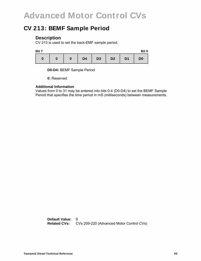
Advanced Motor Control CVs
Tsunami2 Diesel Technical Reference 95
CV 213: BEMF Sample Period Description CV 213 is used to set the back-EMF sample period. Bit 7 Bit 0
0 0 0 D4 D3 D2 D1 D0
D0-D4: BEMF Sample Period 0: Reserved
Additional Information Values from 0 to 31 may be entered into bits 0-4 (D0-D4) to set the BEMF Sample Period that specifies the time period in mS (milliseconds) between measurements.
Default Value: 9 Related CVs: CVs 209-220 (Advanced Motor Control CVs)

Advanced Motor Control CVs
Tsunami2 Diesel Technical Reference 96
CV 214: BEMF Sample Aperture Time Description CV 214 is used to set the back-EMF sample aperture time.
Bit 7 Bit 0
0 0 0 0 D3 D2 D1 D0
D0-D3: BEMF Sample Aperture Time 0: Reserved
Additional Information Values from 0 to 15 may be entered into bits 0-4 (D0-D4) to set the BEMF Sample Aperture Time Period that specifies the time period in mS (milliseconds) that the aperture is open.
Default Value: 6 Related CVs: CVs 209-220 (Advanced Motor Control CVs)
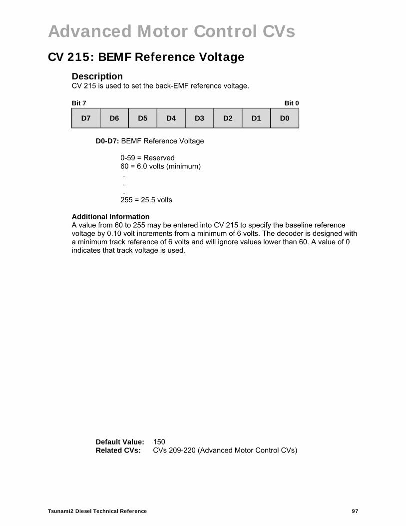
Advanced Motor Control CVs
Tsunami2 Diesel Technical Reference 97
CV 215: BEMF Reference Voltage Description CV 215 is used to set the back-EMF reference voltage. Bit 7 Bit 0
D7 D6 D5 D4 D3 D2 D1 D0
D0-D7: BEMF Reference Voltage
0-59 = Reserved 60 = 6.0 volts (minimum). . .
255 = 25.5 volts Additional Information A value from 60 to 255 may be entered into CV 215 to specify the baseline reference voltage by 0.10 volt increments from a minimum of 6 volts. The decoder is designed with a minimum track reference of 6 volts and will ignore values lower than 60. A value of 0 indicates that track voltage is used.
Default Value: 150 Related CVs: CVs 209-220 (Advanced Motor Control CVs)

Advanced Motor Control CVs
Tsunami2 Diesel Technical Reference 98
CV 216: Motor Speed Step Deadband Description CV 216 is used to determine the speed step at which voltage is first applied to the motor output to put the locomotive into motion. Bit 7 Bit 0
0 D6 D5 D4 D3 D2 D1 D0
D0-D6: Motor Speed Step Deadband
0 = Disabled 1 = Speed-step 1 . . .
127 = Speed-step 127
0: Reserved
Default Value: 0 Related CVs: CVs 209-220 (Advanced Motor Control CVs)

Advanced Motor Control CVs
Tsunami2 Diesel Technical Reference 99
CV 217: Motor Control Register Description CV 217 is used to enable back-EMF control and auto-stop.
Bit 7 Bit 0
0 0 0 0 STP 0 BEMF 0
BEMF: Back-EMF Enable
0 = Back-EMF disabled 1 = Back-EMF enabled
STP: Auto-Stop Enable
0 = Auto-stop disabled 1 = Auto-stop enabled
Additional Information Setting bit 1 (BEMF) to 1 will enable back-EMF motor control. Setting bit 3 (STP) to 1 will enable the auto-stop feature. When auto-stop is enabled, direction commands will bring the motor to a full stop for a duration of 500ms before the decoder changes locomotive direction.
Default Value: 10 Related CVs: CVs 209-220 (Advanced Motor Control CVs)

Advanced Motor Control CVs
Tsunami2 Diesel Technical Reference 100
CV 218: Analog Mode Motor Start Voltage Description CV 218 is sets the track voltage in analog mode at which voltage is first applied to the motor. Bit 7 Bit 0
D7 D6 D5 D4 D3 D2 D1 D0
D0-D7: Analog Mode Motor Start Voltage
Additional Information A value from 0 to 255 may be entered into CV 218 to adjust the analog mode motor start voltage. Starting voltage is calculated as:
Starting Voltage = (CV 218 ÷ 10) + 6V
Entering a value of 0 into CV 218 will set the starting voltage to 6V. Entering a value of 255 into CV 218 will set the starting voltage to the maximum setting. Set CV 218 to the lowest value that still achieves desired results. The motor will not start when the voltage level in CV 218 is set to an excessively high value. Note: Starting the motor at too low a voltage can cause the voltage from the powerpack to sag, resulting in a condition where the decoder loses power when attempting to power the motor.
Default Value: 15 Related CVs: CV 12 (Alternate Power Source)
CV 29 (Configuration Data 1) CVs 209-220 (Advanced Motor Control CVs)

Advanced Motor Control CVs
Tsunami2 Diesel Technical Reference 101
CV 219: Analog Mode Engine Start Voltage Description CV 219 is provided for adjusting the track Voltage in analog mode at which the engine exhaust sound begins. This feature is intended for use only when BEMF (see CV217) is disabled. If using BEMF, ensure CV 219 is set to 0. If BEMF is disabled, increasing the value in this CV will ‘delay’ the start of the engine exhaust sound to a higher track voltage than the track voltage at which the motor is first powered. The actual relation of this CV to the effect is a given as a percentage of the motor voltage output, i.e., if the CV is set to 128 (50% of 256), then the exhaust sound will first begin to play when a 50% voltage is applied to the motor. Bit 7 Bit 0
D7 D6 D5 D4 D3 D2 D1 D0
D0-D7: Analog Mode Engine Start Voltage
Default Value: 15 Related CVs: CV 12 (Alternate Power Source)
CV 29 (Configuration Data 1) CVs 209-220 (Advanced Motor Control CVs)

Advanced Motor Control CVs
Tsunami2 Diesel Technical Reference 102
CV 220: Constant Brake Distance Description CV 220 determines the fixed distance over which the locomotive will decelerate to a stop after setting the throttle to zero. Constant Brake Distance enables the train to be stopped in a set fixed distance regardless of speed. Bit 7 Bit 0
D7 D6 D5 D4 D3 D2 D1 D0
D0-D7: Constant Brake Distance
Additional Information Entering a value from 1 to 255 into CV 220 will adjust the constant brake distance proportionally to the value in CV 220, i.e., if the stopping distance = 1 foot with a value of 64 in CV 220, then a value of 128 would result in a stopping distance of 2 feet.. Entering a value of 0 into CV 220 will disable the constant brake distance feature, as will disabling Back-EMF in CV 217.
Default Value: 0 Related CVs: CV 4, CV 217
CVs 116-118

Audio Control CVs
Tsunami2 Diesel Technical Reference 103
Audio Control CVs
CV 224: High-Pass Filter Cutoff Frequency Description CV 224 is used to adjust the cutoff frequency of the decoder’s high-pass output filter. Bit 7 Bit 0
D7 D6 D5 D4 D3 D2 D1 D0
D0-D7: Cutoff Frequency
0 = High-pass filter disabled1 = 20Hz . . .
255 = 1kHz Additional Information Entering a value from 1 to 255 into CV 224 will adjust the high-pass filter cutoff frequency from 20Hz to 1kHz. A value of 0 will disable the high-pass filter.
Default Value: 20 Related CVs: CVs 224-236 (Audio Control CVs)

Audio Control CVs
Tsunami2 Diesel Technical Reference 104
CV 225: Equalizer Control Register Description CV 225 is used for presetting the cut/boost levels of the 7-band equalizer to accommodate a range of speaker sizes or to allow each band of the equalizer to be adjusted according to CVs 226-232 (Cut/Boost Controls).
Bit 7 Bit 0
0 0 0 0 0 EQ2 EQ1 EQ0
EQ0-EQ2: Equalizer Presets
0 = Flat (disabled) 1 = Micro speaker (smaller than 1”)2 = Small speaker (from 1” to 2”) 3 = Medium speaker (from 2” to 4”)4 = Large speaker (larger than 4”) 5 = Reserved 6 = Reserved 7 = User-adjustable (CVs 226-232)
0: Reserved
Additional Information Setting CV 225 to a value from 1 to 4 will adjust the 7-band equalizer frequency response according to speaker size. Setting CV 225 to a value of 7 allows the cut/boost levels of the 7-band equalizer to be adjusted using CVs 226-232. Setting CV 225 to a value of 0 will disable the equalizer, i.e., all frequency levels will be set to 0dB (flat).
Default Value: 0 Related CVs: CVs 224-236 (Audio Control CVs)
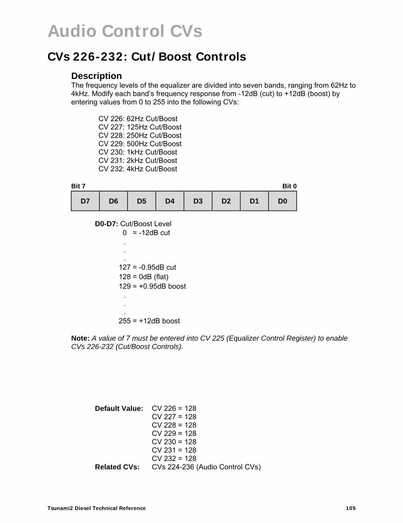
Audio Control CVs
Tsunami2 Diesel Technical Reference 105
CVs 226-232: Cut/Boost Controls Description The frequency levels of the equalizer are divided into seven bands, ranging from 62Hz to 4kHz. Modify each band’s frequency response from -12dB (cut) to +12dB (boost) by entering values from 0 to 255 into the following CVs:
CV 226: 62Hz Cut/Boost CV 227: 125Hz Cut/BoostCV 228: 250Hz Cut/BoostCV 229: 500Hz Cut/BoostCV 230: 1kHz Cut/Boost CV 231: 2kHz Cut/Boost CV 232: 4kHz Cut/Boost
Bit 7 Bit 0
D7 D6 D5 D4 D3 D2 D1 D0
D0-D7: Cut/Boost Level
0 = -12dB cut . . .
127 = -0.95dB cut 128 = 0dB (flat) 129 = +0.95dB boost
.
.
.
255 = +12dB boost
Note: A value of 7 must be entered into CV 225 (Equalizer Control Register) to enable CVs 226-232 (Cut/Boost Controls).
Default Value: CV 226 = 128 CV 227 = 128 CV 228 = 128 CV 229 = 128 CV 230 = 128 CV 231 = 128 CV 232 = 128
Related CVs: CVs 224-236 (Audio Control CVs)

Audio Control CVs
Tsunami2 Diesel Technical Reference 106
CV 233: Reverb Control Register Description CV 233 is used to select from preset reverb settings or select the user-adjustable option, as defined by CVs 234-236 and CVs 161-192 (Reverb Mixer). Bit 7 Bit 0
0 0 0 0 0 RV2 RV1 RV0
RV0-RV2: Reverb Presets
0 = Disabled 1 = Light Reverb 2 = Medium Reverb 3 = Heavy Reverb 4 = Short Echo 5 = Long Echo 6 = Reserved 7 = User-adjustable (CVs 234-236)
Default Value: 1 Related CVs: CVs 161-192 (Reverb Mixer)
CVs 224-236 (Audio Control CVs)

Audio Control CVs
Tsunami2 Diesel Technical Reference 107
CV 234: Reverb Output Level Description CV 234 is used to determine the amount of reverb signal that is mixed back with the original audio signal. Bit 7 Bit 0
D7 D6 D5 D4 D3 D2 D1 D0
D0-D7: Reverb Output Level
0 = 0% . . .
128 = 50% . . .
255 = 100%
Additional Information Entering values from 0 to 100 will adjust the reverb output level from 0% to 100%.
Default Value: 0 Related CVs: CVs 161-192 (Reverb Mixer)
CVs 224-236 (Audio Control CVs)

Audio Control CVs
Tsunami2 Diesel Technical Reference 108
CV 235: Reverb Delay Time Description CV 235 is used to determine the overall reverb delay time from 0 to 255ms. Bit 7 Bit 0
D7 D6 D5 D4 D3 D2 D1 D0
D0-D7: Reverb Delay Time
0 = Minimum delay time. . .
255 = Maximum delay time Additional Information A longer delay time corresponds to a greater distance between the sound source and the reflecting surfaces and will generally result in an increased level of reverb. Reverb delay time is calculated as:
Delay Time = CV 235 × 1ms
Default Value: 0 Related CVs: CVs 161-192 (Reverb Mixer)
CVs 224-236 (Audio Control CVs)

Audio Control CVs
Tsunami2 Diesel Technical Reference 109
CV 236: Reverb Feedback Gain Level Description CV 236 is used to determine the percentage of the reverb output that is mixed back into the input and creates the effect of multiple sound reflections, each diminishing in amplitude over time. Bit 7 Bit 0
D7 D6 D5 D4 D3 D2 D1 D0
D0-D7: Reverb Feedback Gain Level
0 = 0% feedback . . .
64 = 25% feedback (d. . .
255 = 100% feedback Additional Information High feedback settings (greater than a value of 200) should be avoided, as they can create some undesirable effects. Adjust this CV starting with a low initial value and increase in small steps.
Default Value: 0 Related CVs: CVs 161-192 (Reverb Mixer)
CVs 224-236 (Audio Control CVs)
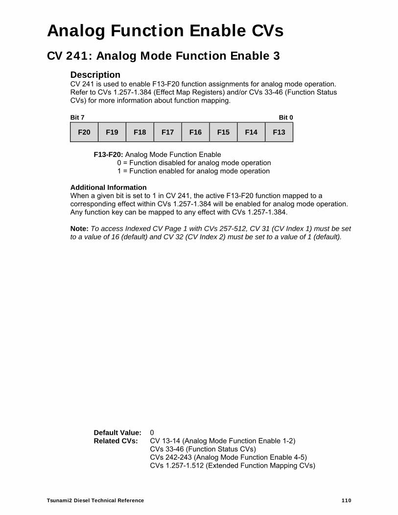
Analog Function Enable CVs
Tsunami2 Diesel Technical Reference 110
Analog Function Enable CVs
CV 241: Analog Mode Function Enable 3 Description CV 241 is used to enable F13-F20 function assignments for analog mode operation. Refer to CVs 1.257-1.384 (Effect Map Registers) and/or CVs 33-46 (Function Status CVs) for more information about function mapping.
Bit 7 Bit 0
F20 F19 F18 F17 F16 F15 F14 F13
F13-F20: Analog Mode Function Enable
0 = Function disabled for analog mode operation 1 = Function enabled for analog mode operation
Additional Information When a given bit is set to 1 in CV 241, the active F13-F20 function mapped to a corresponding effect within CVs 1.257-1.384 will be enabled for analog mode operation. Any function key can be mapped to any effect with CVs 1.257-1.384. Note: To access Indexed CV Page 1 with CVs 257-512, CV 31 (CV Index 1) must be set to a value of 16 (default) and CV 32 (CV Index 2) must be set to a value of 1 (default).
Default Value: 0 Related CVs: CV 13-14 (Analog Mode Function Enable 1-2)
CVs 33-46 (Function Status CVs) CVs 242-243 (Analog Mode Function Enable 4-5) CVs 1.257-1.512 (Extended Function Mapping CVs)

Analog Function Enable CVs
Tsunami2 Diesel Technical Reference 111
CV 242: Analog Mode Function Enable 4 Description CV 242 is used to enable F21-F28 function assignments for analog mode operation. Refer to CVs 1.257-1.384 (Effect Map Registers) and/or CVs 33-46 (Function Status CVs) for more information about function mapping. Bit 7 Bit 0
F28 F27 F26 F25 F24 F23 F22 F21
F21-F28: Analog Mode Function Enable
0 = Function disabled for analog mode operation 1 = Function enabled for analog mode operation
Additional Information When a given bit is set to 1 in CV 242, the active F21-F28 function mapped to a corresponding effect within CVs 1.257-1.384 will be enabled for analog mode operation. Any function key can be mapped to any effect with CVs 1.257-1.384. Note: To access Indexed CV Page 1 with CVs 257-512, CV 31 (CV Index 1) must be set to a value of 16 (default) and CV 32 (CV Index 2) must be set to a value of 1 (default).
Default Value: 0 Related CVs: CV 13-14 (Analog Mode Function Enable 1-2)
CVs 33-46 (Function Status CVs) CVs 241 and 243 (Analog Mode Function Enable 3 and 5)CVs 1.257-1.512 (Extended Function Mapping CVs)

Analog Function Enable CVs
Tsunami2 Diesel Technical Reference 112
CV 243: Analog Mode Function Enable 5 Description CV 243 is used in conjunction with CVs 1.385-1.512 (Effect Auxiliary Map Registers) to enable automatic effects for analog mode operation.
Bit 7 Bit 0
0 0 0 0 REVS FWDS REVD FWDD
FWDD: Forward-Driving
0 = Disabled 1 = Effect active when moving in forward direction
REVD: Reverse-Driving 0 = Disabled 1 = Effect active when moving in reverse direction
FWDS: Forward-Standing 0 = Disabled 1 = Effect active when stopped in forward direction
REVS: Reverse-Standing 0 = Disabled 1 = Effect active when stopped in reverse direction
0: Reserved
Note: To access Indexed CV Page 1 with CVs 257-512, CV 31 (CV Index 1) must be set to a value of 16 (default) and CV 32 (CV Index 2) must be set to a value of 1 (default).
Default Value: 0 Related CVs: CV 13-14 (Analog Mode Function Enable 1-2)
CVs 33-46 (Function Status CVs) CVs 241-242 (Analog Mode Function Enable 3-4) CVs 1.257-1.512 (Extended Function Mapping CVs)

Consist Function Enable CVs
Tsunami2 Diesel Technical Reference 113
Consist Function Enable CVs
CV 245: Consist Function Enable 3 Description CV 245 is used to enable F13-F20 function assignments for advanced consist operation. Refer to CVs 1.257-1.384 (Effect Map Registers) and/or CVs 33-46 (Function Status CVs) for more information about function mapping.
Bit 7 Bit 0
F20 F19 F18 F17 F16 F15 F14 F13
F13-F20: Consist Function Enable
0 = Function disabled for consist operation 1 = Function enabled for consist operation
Additional Information When a given bit is set to 1 in CV 245, the active F13-F20 function mapped to a corresponding effect within CVs 1.257-1.384 will be enabled for consist operation. Any function key can be mapped to any effect with CVs 1.257-1.384. Note: To access Indexed CV Page 1 with CVs 257-512, CV 31 (CV Index 1) must be set to a value of 16 (default) and CV 32 (CV Index 2) must be set to a value of 1 (default).
Default Value: 0 Related CVs: CV 19 (Consist Address)
CVs 21-22 (Consist Function Enable 1-2) CVs 33-46 (Function Status CVs) CVs 246-247 (Consist Function Enable 4-5) CVs 1.257-1.512 (Extended Function Mapping CVs)

Consist Function Enable CVs
Tsunami2 Diesel Technical Reference 114
CV 246: Consist Function Enable 4 Description CV 246 is used to enable F21-F28 function assignments for advanced consist operation. Refer to CVs 1.257-1.384 (Effect Map Registers) and/or CVs 33-46 (Function Status CVs) for more information about function mapping.
Bit 7 Bit 0
F28 F27 F26 F25 F24 F23 F22 F21
F21-F28: Consist Function Enable
0 = Function disabled for consist operation 1 = Function enabled for consist operation
Additional Information When a given bit is set to 1 in CV 246, the active F21-F28 function mapped to a corresponding effect within CVs 1.257-1.384 will be enabled for consist operation. Any function key can be mapped to any effect with CVs 1.257-1.384. Note: To access Indexed CV Page 1 with CVs 257-512, CV 31 (CV Index 1) must be set to a value of 16 (default) and CV 32 (CV Index 2) must be set to a value of 1 (default).
Default Value: 0 Related CVs: CV 19 (Consist Address)
CVs 21-22 (Consist Function Enable 1-2) CVs 33-46 (Function Status CVs) CVs 245 and 247 (Consist Function Enable 3 and 5)CVs 1.257-1.512 (Extended Function Mapping CVs)
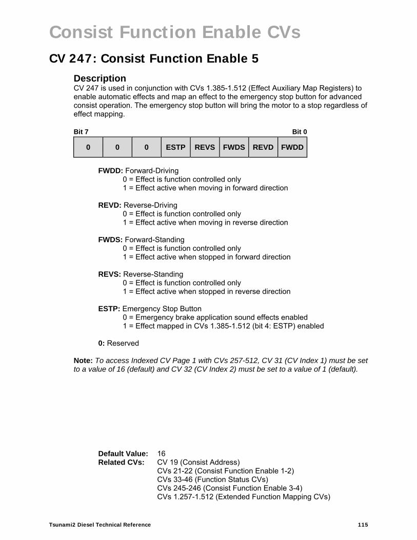
Consist Function Enable CVs
Tsunami2 Diesel Technical Reference 115
CV 247: Consist Function Enable 5 Description CV 247 is used in conjunction with CVs 1.385-1.512 (Effect Auxiliary Map Registers) to enable automatic effects and map an effect to the emergency stop button for advanced consist operation. The emergency stop button will bring the motor to a stop regardless of effect mapping. Bit 7 Bit 0
0 0 0 ESTP REVS FWDS REVD FWDD
FWDD: Forward-Driving
0 = Effect is function controlled only 1 = Effect active when moving in forward direction
REVD: Reverse-Driving 0 = Effect is function controlled only 1 = Effect active when moving in reverse direction
FWDS: Forward-Standing 0 = Effect is function controlled only 1 = Effect active when stopped in forward direction
REVS: Reverse-Standing 0 = Effect is function controlled only 1 = Effect active when stopped in reverse direction
ESTP: Emergency Stop Button 0 = Emergency brake application sound effects enabled 1 = Effect mapped in CVs 1.385-1.512 (bit 4: ESTP) enabled
0: Reserved
Note: To access Indexed CV Page 1 with CVs 257-512, CV 31 (CV Index 1) must be set to a value of 16 (default) and CV 32 (CV Index 2) must be set to a value of 1 (default).
Default Value: 16 Related CVs: CV 19 (Consist Address)
CVs 21-22 (Consist Function Enable 1-2) CVs 33-46 (Function Status CVs) CVs 245-246 (Consist Function Enable 3-4) CVs 1.257-1.512 (Extended Function Mapping CVs)
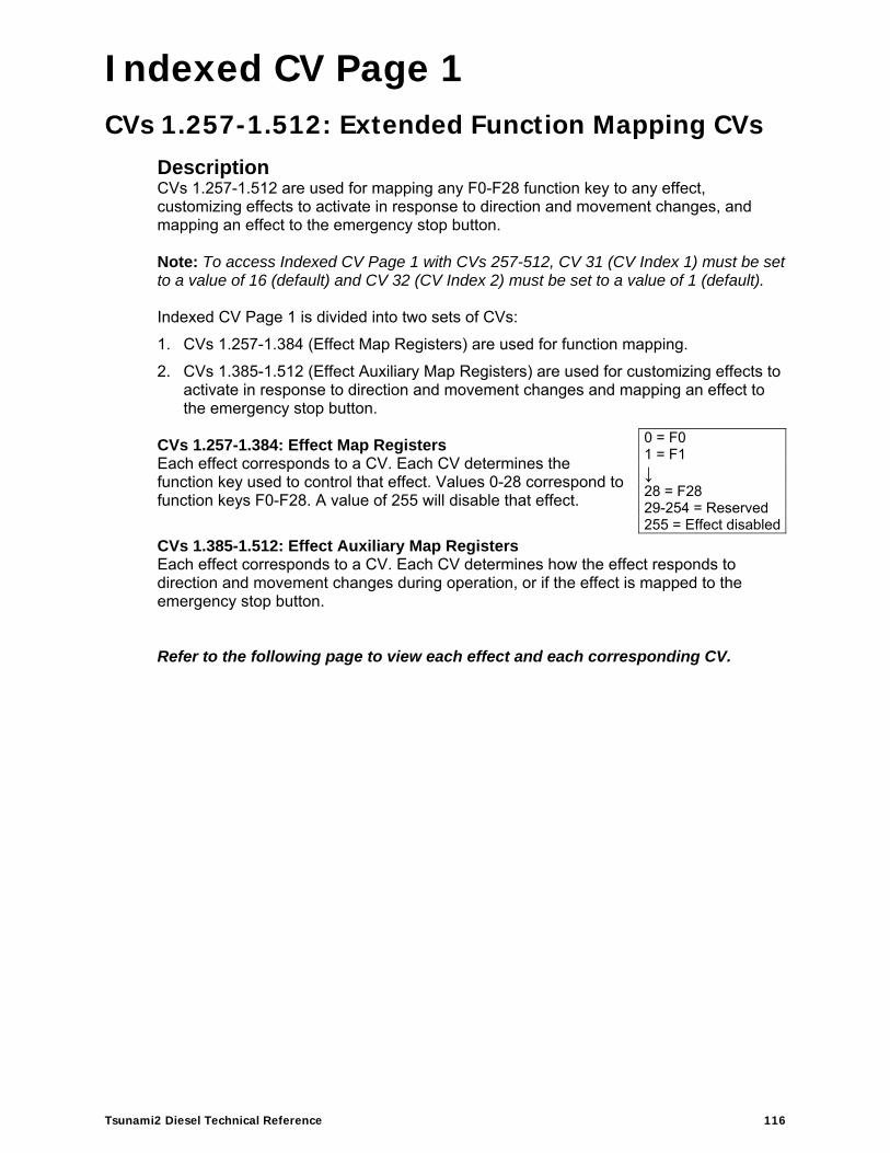
Indexed CV Page 1
Tsunami2 Diesel Technical Reference 116
Indexed CV Page 1
CVs 1.257-1.512: Extended Function Mapping CVs Description CVs 1.257-1.512 are used for mapping any F0-F28 function key to any effect, customizing effects to activate in response to direction and movement changes, and mapping an effect to the emergency stop button. Note: To access Indexed CV Page 1 with CVs 257-512, CV 31 (CV Index 1) must be set to a value of 16 (default) and CV 32 (CV Index 2) must be set to a value of 1 (default). Indexed CV Page 1 is divided into two sets of CVs:
1. CVs 1.257-1.384 (Effect Map Registers) are used for function mapping.
2. CVs 1.385-1.512 (Effect Auxiliary Map Registers) are used for customizing effects to activate in response to direction and movement changes and mapping an effect to the emergency stop button.
CVs 1.257-1.384: Effect Map Registers Each effect corresponds to a CV. Each CV determines the function key used to control that effect. Values 0-28 correspond to function keys F0-F28. A value of 255 will disable that effect.
CVs 1.385-1.512: Effect Auxiliary Map Registers Each effect corresponds to a CV. Each CV determines how the effect responds to direction and movement changes during operation, or if the effect is mapped to the emergency stop button. Refer to the following page to view each effect and each corresponding CV.
0 = F0 1 = F1 ↓ 28 = F28 29-254 = Reserved 255 = Effect disabled

Indexed CV Page 1
Tsunami2 Diesel Technical Reference 117
CVs 1.257-1.512: Extended Function Mapping CVs Effect Map Registers Effect Auxiliary Map Registers
CV 1.257: Headlight CV 1.385: Headlight
CV 1.258: Backup Light CV 1.386: Backup Light
CV 1.259: FX3 Effect CV 1.387: FX3 Effect
CV 1.260: FX4 Effect CV 1.388: FX4 Effect
CV 1.261: FX5 Effect CV 1.389: FX5 Effect
CV 1.262: FX6 Effect CV 1.390: FX6 Effect
CVs 1.263-1.272: Reserved CVs 1.391-1.400: Reserved
CV 1.273: Dimmer CV 1.401: Dimmer
CV 1.274: Mute CV 1.402: Mute
CV 1.275: Independent/Train Brake CV 1.403: Independent/Train Brake
CV 1.276: Half-Speed CV 1.404: Half-Speed
CV 1.277: Momentum Override CV 1.405: Momentum Override
CV 1.278: Grade-Crossing Signal CV 1.406: Grade-Crossing Signal
CV 1.279: Forward Whistle Signal CV 1.407: Forward Whistle Signal
CV 1.280: Reverse Whistle Signal CV 1.408: Reverse Whistle Signal
CV 1.281: Stop Whistle Signal CV 1.409: Stop Whistle Signal
CV 1.282: Reserved CV 1.410: Reserved
CV 1.283: Brake Select CV 1.411: Brake Select
CV 1.284: Alternate Mixer CV 1.412: Alternate Mixer
CV 1.285: RPM+ CV 1.413: RPM+
CV 1.286: RPM- CV 1.414: RPM-
CVs 1.287-1.296: Reserved CVs 1.415-1.424: Reserved
CV 1.297: Airhorn CV 1.425: Airhorn
CV 1.298: Bell CV 1.426: Bell
CV 1.299: Dynamic Brake CV 1.427: Dynamic Brake
CV 1.300: Short Airhorn CV 1.428: Short Airhorn
CV 1.301: Straight-to-Eight CV 1.429: Straight-to-Eight
CV 1.302: General Service CV 1.430: General Service
CV 1.303: HEP Mode CV 1.431: HEP Mode
CV 1.304: Cab Chatter CV 1.432: Cab Chatter
CV 1.305: Couple CV 1.433: Couple
CV 1.306: Uncouple CV 1.434: Uncouple
CV 1.307: Reserved CV 1.435: Reserved
CV 1.308: Handbrake CV 1.436: Handbrake
CV 1.309: Sander Valve CV 1.437: Sander Valve
CV 1.310: Reserved CV 1.438: Reserved
CV 1.311: All Aboard/Coach Doors CV 1.439: All Aboard/Coach Doors
CV 1.312: Steam Generator CV 1.440: Steam Generator
CV 1.313: Fuel Loading CV 1.441: Fuel Loading
CVs 1.314-1.320: Reserved CVs 1.442-1.448: Reserved
CV 1.321: E-Brake App. CV 1.449: E-Brake App.
CVs 1.322-1.384: Reserved CVs 1.450-1.512: Reserved
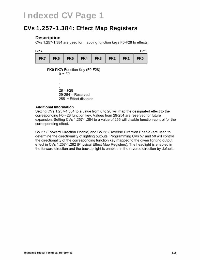
Indexed CV Page 1
Tsunami2 Diesel Technical Reference 118
CVs 1.257-1.384: Effect Map Registers Description CVs 1.257-1.384 are used for mapping function keys F0-F28 to effects. Bit 7 Bit 0
FK7 FK6 FK5 FK4 FK3 FK2 FK1 FK0
FK0-FK7: Function Key (F0-F28)
0 = F0 . . .
28 = F28 29-254 = Reserved 255 = Effect disabled
Additional Information Setting CVs 1.257-1.384 to a value from 0 to 28 will map the designated effect to the corresponding F0-F28 function key. Values from 29-254 are reserved for future expansion. Setting CVs 1.257-1.384 to a value of 255 will disable function-control for the corresponding effect. CV 57 (Forward Direction Enable) and CV 58 (Reverse Direction Enable) are used to determine the directionality of lighting outputs. Programming CVs 57 and 58 will control the directionality of the corresponding function key mapped to the given lighting output effect in CVs 1.257-1.262 (Physical Effect Map Registers). The headlight is enabled in the forward direction and the backup light is enabled in the reverse direction by default.

Indexed CV Page 1
Tsunami2 Diesel Technical Reference 119
Default Function Assignments
F0-F28 Effect CV Value
F0(f) Headlight CV 1.257 0
F0(r) Backup Light CV 1.258 0
F1 Bell CV 1.298 1
F2 Airhorn CV 1.297 2
F3 Short Airhorn CV 1.300 3
F4 Dynamic Brake CV 1.299 4
F5 RPM+ CV 1.285 5
F6 RPM- CV 1.286 6
F7 Dimmer CV 1.273 7
F8 Mute CV 1.274 8
F9 Grade-Crossing Signal CV 1.278 9
F10 Straight-to-Eight CV 1.301 10
F11 Independent/Train Brake CV 1.275 11
F12 Brake Select CV 1.283 12
F13 Couple CV 1.305 13
F13 Uncouple CV 1.306 13
F14 Half-Speed CV 1.276 14
F14 Momentum Override CV 1.277 14
F15 Handbrake CV 1.308 15
F16 HEP Mode CV 1.303 16
F17 Fuel Loading CV 1.313 17
F18 General Service CV 1.302 18
F19 Not Assigned Not Assigned 19
F20 Steam Generator CV 1.312 20
F21 Sander Valve CV 1.309 21
F22 Cab Chatter CV 1.304 22
F23 All Aboard/Coach Doors CV 1.311 23
F24 FX3 Output CV 1.259 24
F25 FX4 Output CV 1.260 25
F26 FX5 Output CV 1.261 26
F27 FX6 Output CV 1.262 27
F28 Not Assigned Not Assigned 28
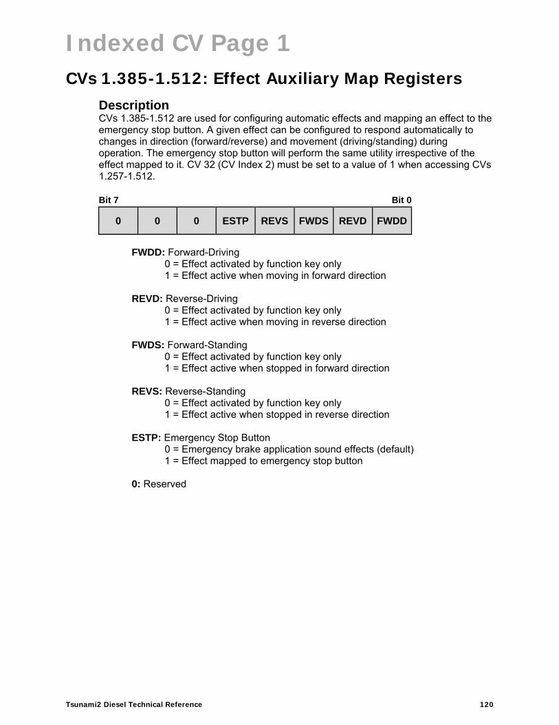
Indexed CV Page 1
Tsunami2 Diesel Technical Reference 120
CVs 1.385-1.512: Effect Auxiliary Map Registers Description CVs 1.385-1.512 are used for configuring automatic effects and mapping an effect to the emergency stop button. A given effect can be configured to respond automatically to changes in direction (forward/reverse) and movement (driving/standing) during operation. The emergency stop button will perform the same utility irrespective of the effect mapped to it. CV 32 (CV Index 2) must be set to a value of 1 when accessing CVs 1.257-1.512. Bit 7 Bit 0
0 0 0 ESTP REVS FWDS REVD FWDD
FWDD: Forward-Driving
0 = Effect activated by function key only 1 = Effect active when moving in forward direction
REVD: Reverse-Driving 0 = Effect activated by function key only 1 = Effect active when moving in reverse direction
FWDS: Forward-Standing 0 = Effect activated by function key only 1 = Effect active when stopped in forward direction
REVS: Reverse-Standing 0 = Effect activated by function key only 1 = Effect active when stopped in reverse direction
ESTP: Emergency Stop Button
0 = Emergency brake application sound effects (default) 1 = Effect mapped to emergency stop button
0: Reserved

Indexed CV Page 2
Tsunami2 Diesel Technical Reference 121
Indexed CV Page 2
CVs 2.289-2.320: Alternate Mixer Volume Levels Description CVs 2.289-2.320 are used to set the alternate volume levels of each sound effect. Turning on the alternate mixer function will set sound effect volume to alternate mixer channel volume levels in place of the primary mixer channel volume levels in CVs 129-160 (Primary Mixer Volume Levels). Note: To access Indexed CV Page 2 with CVs 257-512, CV 31 (CV Index 1) must be set to a value of 16 (default) and CV 32 (CV Index 2) must be set to a value of 2. Bit 7 Bit 0
MIX7 MIX6 MIX5 MIX4 MIX3 MIX2 MIX1 MIX0
MIX0-MIX7: Alternate Mixer Channel Volume
0 = 0% volume . . .
255 = 100% volume
Related CVs: CV 128 (Master Volume) CVs 129-160 (Primary Mixer Volume Levels)

Indexed CV Page 2
Tsunami2 Diesel Technical Reference 122
CVs 2.289-2.320: Alternate Mixer Volume Levels
CV Sound Effect Default Value
2.289 Airhorn 112
2.290 Bell 42
2.291 Prime Mover 75
2.292 Air Compressor 50
2.293 Dynamic Brake 62
2.294 Radiator Fans 37
2.295 Alarm Bell 30
2.296 Reserved 0
2.297 Coupler 64
2.298 Train Brake Apply/Release 64
2.299 Independent Brake Apply 50
2.300 Independent Brake Release 35
2.301 Reserved 0
2.302 Reserved 0
2.303 Poppet Valve 30
2.304 Steam Generator 25
2.305 Cab Doors 64
2.306 Reserved 0
2.307 Relay Clicks 64
2.308 E-Brake App. 35
2.309 Glad Hand Release 75
2.310 All Aboard/Coach Doors 96
2.311 Reserved 0
2.312 Reserved 0
2.313 Clickety-Clack 75
2.314 Sander Valve 5
2.315 Fuel Loading 25
2.316 Air Conditioner 10
2.317 Wrenches 25
2.318 Pneumatic Oilers 20
2.319 Toilet Flush 10
2.320 Cab Chatter 30

Indexed CV Page 2
Tsunami2 Diesel Technical Reference 123
CVs 2.503-2.512: DDE Control CVs Description CVs 2.503-2.512 are used to adjust parameters of the Dynamic Digital Exhaust (DDE) processor. Configuring DDE CVs allows the engine exhaust sound effects to be modified in response to motor load and/or speed during operation. Note: To access Indexed CV Page 2 with CVs 257-512, CV 31 (CV Index 1) must be set to a value of 16 (default) and CV 32 (CV Index 2) must be set to a value of 2.
CV 2.503: DDE Load Offset Description The value of CV 2.503 determines the minimum load required by the motor to move the model. Bit 7 Bit 0
D7 D6 D5 D4 D3 D2 D1 D0
D0-D7: DDE Load Offset
Additional Information Entering values from 1 to 254 into CV 2.503 will set the DDE load offset. Increasing the value in CV2.503 will modify the operation of the DDE processor such that the locomotive will sound like it is under a lighter load. Decreasing the value in CV 2.503 will modify the DDE processor such that the locomotive will sound like it is under a heavier load. Entering a value of 255 into CV 2.503 will tell the DDE processor that the locomotive is currently operating under a ‘no-load’ condition. Use the following steps:
1. Set the throttle to speed-step 1.
2. Ensure the locomotive is running on level track (with no external loads, such as rolling stock), then enter a value of 255 into CV 2.503.
After setting CV 2.503 to 255, the CV will be reprogrammed with a value corresponding to the measured load. CV 2.512 (DDE Load Sensitivity) is set to 0 by default. In order to hear the changes made to CV 2.503, CV 2.512 must be set to a non-zero value (ex., 32).
Default Value: 60 Related CVs: CV 128 (Master Volume)
CVs 129-160 (Primary Mixer Volume Levels)CVs 2.503-2.512 (DDE Control CVs)

Indexed CV Page 2
Tsunami2 Diesel Technical Reference 124
CV 2.504: DDE Load Slope Description The value of CV 2.504 determines the load required to increase the speed of the motor. Bit 7 Bit 0
D7 D6 D5 D4 D3 D2 D1 D0
D0-D7: DDE Load Slope
Additional Information Increasing the value in CV2.504 will modify the operation of the DDE processor such that the locomotive will sound like it is under a lighter load. Decreasing the value in CV 2.504 will modify the DDE processor such that the locomotive will sound like it is under a heavier load. Entering a value of 255 into CV 2.504 will tell the DDE processor that the locomotive is currently operating under a ‘no-load’ condition. Use the following steps:
1. Increase the throttle to a moderate speed for your layout (generally between speed-step 25 and speed-step 40).
2. Ensure the locomotive is running on level track (with no external loads, such as rolling stock), then enter a value of 255 into CV 2.504.
After setting CV 2.504 to 255, the CV will be reprogrammed with a value corresponding to the measured load. CV 2.512 (DDE Load Sensitivity) is set to 0 by default. In order to hear the changes made to CV 2.504, CV 2.512 must be set to a non-zero value (ex., 32).
Default Value: 150 Related CVs: CV 128 (Master Volume)
CVs 129-160 (Primary Mixer Volume Levels)CVs 2.503-2.512 (DDE Control CVs)

Indexed CV Page 2
Tsunami2 Diesel Technical Reference 125
CV 2.507: DDE Prime Mover Low Volume Limit Description CV 2.507 is used to determine the maximum attenuation level of the prime mover sound effect when the motor is operating at light loads. The prime mover low volume limit setting will be added to the corresponding mixer channel setting. Bit 7 Bit 0
D7 D6 D5 D4 D3 D2 D1 D0
D0-D7: DDE Prime Mover Low Volume Limit
0 = 0dB 1 = -0.047dB. . .
255 = -12dB
Default Value: 0 Related CVs: CV 128 (Master Volume)
CVs 129-160 (Primary Mixer Volume Levels)CVs 2.503-2.512 (DDE Control CVs)
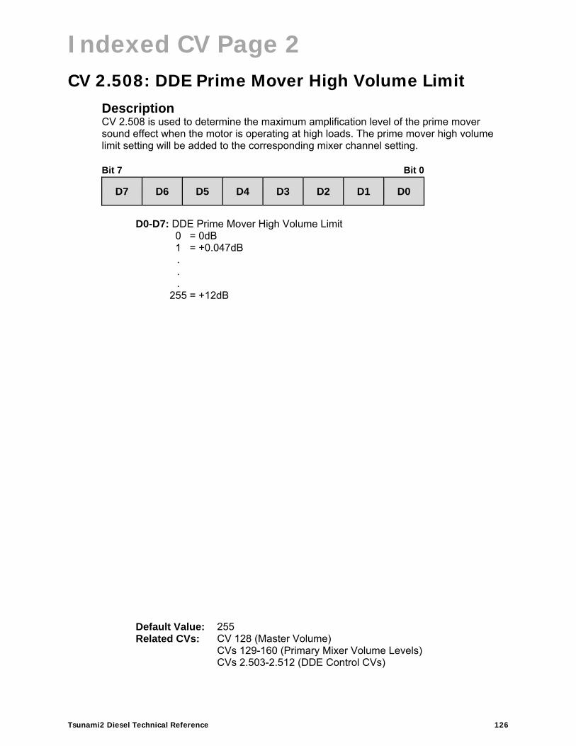
Indexed CV Page 2
Tsunami2 Diesel Technical Reference 126
CV 2.508: DDE Prime Mover High Volume Limit Description CV 2.508 is used to determine the maximum amplification level of the prime mover sound effect when the motor is operating at high loads. The prime mover high volume limit setting will be added to the corresponding mixer channel setting. Bit 7 Bit 0
D7 D6 D5 D4 D3 D2 D1 D0
D0-D7: DDE Prime Mover High Volume Limit
0 = 0dB 1 = +0.047dB. . .
255 = +12dB
Default Value: 255 Related CVs: CV 128 (Master Volume)
CVs 129-160 (Primary Mixer Volume Levels)CVs 2.503-2.512 (DDE Control CVs)
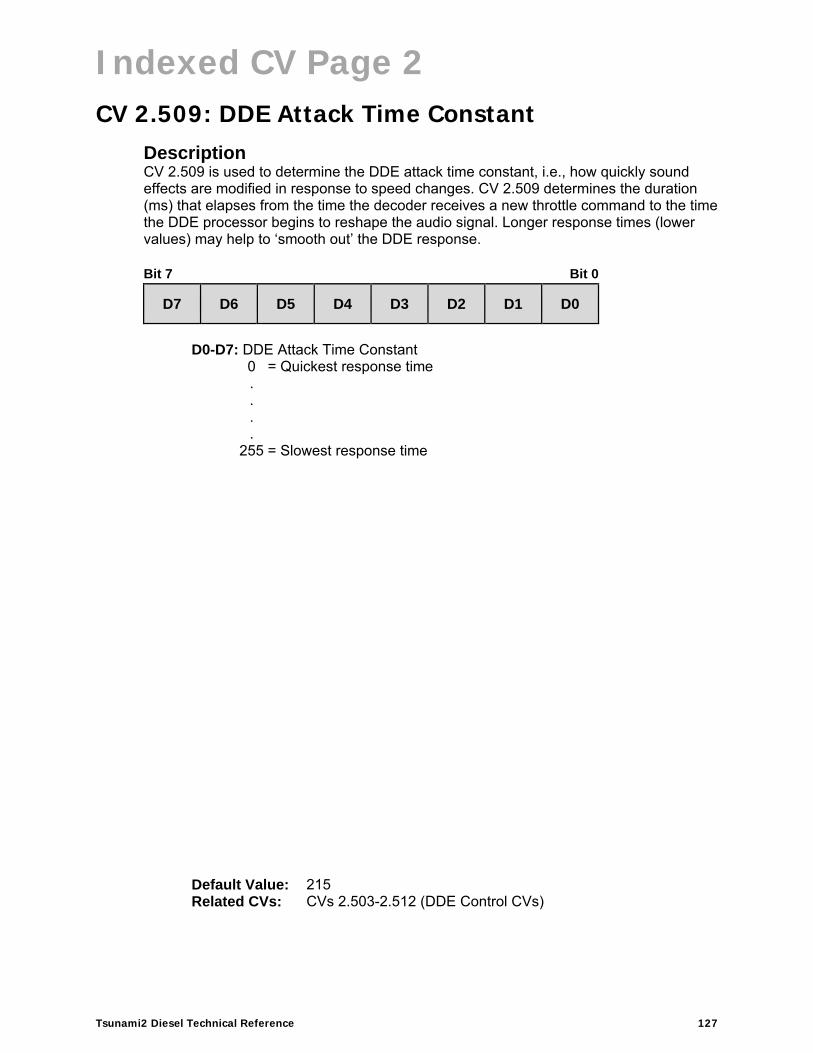
Indexed CV Page 2
Tsunami2 Diesel Technical Reference 127
CV 2.509: DDE Attack Time Constant Description CV 2.509 is used to determine the DDE attack time constant, i.e., how quickly sound effects are modified in response to speed changes. CV 2.509 determines the duration (ms) that elapses from the time the decoder receives a new throttle command to the time the DDE processor begins to reshape the audio signal. Longer response times (lower values) may help to ‘smooth out’ the DDE response. Bit 7 Bit 0
D7 D6 D5 D4 D3 D2 D1 D0
D0-D7: DDE Attack Time Constant
0 = Quickest response time. . . .
255 = Slowest response time
Default Value: 215 Related CVs: CVs 2.503-2.512 (DDE Control CVs)

Indexed CV Page 2
Tsunami2 Diesel Technical Reference 128
CV 2.510: DDE Release Time Constant Description CV 2.510 is used to determine the DDE release time constant, i.e., how quickly sound effects are modified in response to speed changes. CV 2.510 determines the duration (ms) that elapses from the time the DDE processor begins to reshape the audio signal (after receiving a new throttle command) to the time sound effects have been modified accordingly. Longer response times (lower values) may help to ‘smooth out’ the DDE response. Bit 7 Bit 0
D7 D6 D5 D4 D3 D2 D1 D0
D0-D7: DDE Release Time Constant
0 = Quickest response time. . . .
255 = Slowest response time
Default Value: 215 Related CVs: CVs 2.503-2.512 (DDE Control CVs)

Indexed CV Page 2
Tsunami2 Diesel Technical Reference 129
CV 2.511: DDE Throttle Sensitivity Description CV 2.511 is used to adjust the correlation between the throttle setting and speed-related sound effects. When the decoder has momentum programmed, this CV sets how much the load signal is affected by the model accelerating/decelerating. Bit 7 Bit 0
D7 D6 D5 D4 D3 D2 D1 D0
D0-D7: DDE Throttle Sensitivity
0 = Disabled 1 = Minimum sensitivity. . .
255 = Maximum sensitivity Additional Information Setting CV 2.511 to 0 will disable DDE throttle sensing. Setting CV 2.511 to 255 indicates that the cadence and volume of speed-related sound effects will be most sensitive to the throttle setting.
Default Value: 10 Related CVs: CVs 2.503-2.512 (DDE Control CVs)

Indexed CV Page 2
Tsunami2 Diesel Technical Reference 130
CV 2.512: DDE Load Sensitivity Description CV 2.512 is used to adjust the correlation between the throttle setting and motor load sensing. When the decoder has momentum programmed, this CV sets how much the load signal is affected by the model accelerating/decelerating. Bit 7 Bit 0
D7 D6 D5 D4 D3 D2 D1 D0
D0-D7: DDE Load Sensitivity
0 = Disabled 1 = Minimum sensitivity. . .
255 = Maximum sensitivity Additional Information Setting CV 2.512 to 0 will disable DDE load sensing and sound effects will not be modified in response to changes in motor load. Setting CV 2.512 to 255 indicates that the sound and motor responses will be most sensitive to changes in load.
Default Value: 0 Related CVs: CVs 2.503-2.512 (DDE Control CVs)
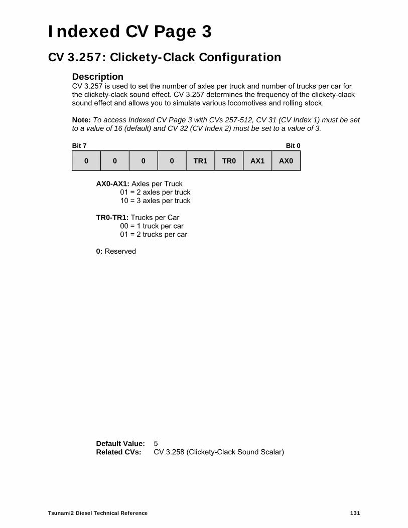
Indexed CV Page 3
Tsunami2 Diesel Technical Reference 131
Indexed CV Page 3
CV 3.257: Clickety-Clack Configuration Description CV 3.257 is used to set the number of axles per truck and number of trucks per car for the clickety-clack sound effect. CV 3.257 determines the frequency of the clickety-clack sound effect and allows you to simulate various locomotives and rolling stock. Note: To access Indexed CV Page 3 with CVs 257-512, CV 31 (CV Index 1) must be set to a value of 16 (default) and CV 32 (CV Index 2) must be set to a value of 3. Bit 7 Bit 0
0 0 0 0 TR1 TR0 AX1 AX0
AX0-AX1: Axles per Truck
01 = 2 axles per truck 10 = 3 axles per truck
TR0-TR1: Trucks per Car
00 = 1 truck per car 01 = 2 trucks per car
0: Reserved
Default Value: 5 Related CVs: CV 3.258 (Clickety-Clack Sound Scalar)

Indexed CV Page 3
Tsunami2 Diesel Technical Reference 132
CV 3.258: Clickety-Clack Sound Scalar Description CV 3.258 is used to set the frequency of the clickety-clack sound effect. The value of CV 3.258 determines the proportion between the speed step and the scale speed (feet per second) used to configure the frequency of the clickety-clack sound effect. Note: To access Indexed CV Page 3 with CVs 257-512, CV 31 (CV Index 1) must be set to a value of 16 (default) and CV 32 (CV Index 2) must be set to a value of 3. Bit 7 Bit 0
SS7 SS6 SS5 SS4 SS3 SS2 SS1 SS0
SS0-SS7: Clickety-Clack Sound Scalar
Additional Information Higher values indicate higher scale speeds and increase the frequency of the clickety-clack sound effect. Entering a value from 1 to 255 into CV 3.258 will adjust the clickety-clack frequency from 0.01ft/s to 2ft/s. Scale speed (ft/s) is calculated as:
Scale Speed (ft/s) = (Speed Step × CV 3.258) ÷ 100 Entering a value of 0 into CV 3.258 will disable the clickety-clack effect.
Default Value: 180 Related CVs: CV 3.257 (Clickety-Clack Rate)


