364
TSX Micro PLCs TSX 3705/3708/3710/3720 Implementation Manual Volume 1 TSX DM 37 xx eng efesotomasyon - telemecanique inverter
efesotomasyon - telemecanique inverter
TSX Micro PLCsTSX 3705/3708/3710/3720Implementation Manual Volume 1TSX DM 37 xx eng

efesotomasyon - telemecanique inverter
2
Related Documentation
efesotomasyon - telemecanique inverter
Related Documentation
At a Glance This manual comprises three volumes. Volume 1,
Processors, Implementation/Diagnostics/Maintenance, Integrated analog, Integrated upcounting, Integrated communication.
Volume 2, Discrete input/output modules, Remote adaptor modules for discrete input/outputs, Process and AS-i supplies.
Volume 3. Analog input/output modules, Counting module, Communication by PCMCIA card.
TSX DM 37 xxE 3

Related Documentation
efesotomasyon - telemecanique inverter
4 TSX DM 37 xxE
efesotomasyon - telemecanique inverter
Table of Contents
About the book . . . . . . . . . . . . . . . . . . . . . . . . . . . . . . . . . . . . . .13
Part I General introduction to a PLC station . . . . . . . . . . . . . . 15At a Glance . . . . . . . . . . . . . . . . . . . . . . . . . . . . . . . . . . . . . . . . . . . . . . . . . . . . . 15
Chapter 1 General introduction to TSX Micro PLCs . . . . . . . . . . . . . . . . .17TSX Micro PLCs . . . . . . . . . . . . . . . . . . . . . . . . . . . . . . . . . . . . . . . . . . . . . . . . . 17
Chapter 2 General introduction to the components of a PLC station. . .19At a Glance . . . . . . . . . . . . . . . . . . . . . . . . . . . . . . . . . . . . . . . . . . . . . . . . . . . . . 19General information about discrete inputs/outputs . . . . . . . . . . . . . . . . . . . . . . . 20Local discrete inputs/outputs in the rack . . . . . . . . . . . . . . . . . . . . . . . . . . . . . . . 21Remote discrete inputs/outputs. . . . . . . . . . . . . . . . . . . . . . . . . . . . . . . . . . . . . . 22Discrete safety inputs/outputs . . . . . . . . . . . . . . . . . . . . . . . . . . . . . . . . . . . . . . . 24Local analog inputs/outputs. . . . . . . . . . . . . . . . . . . . . . . . . . . . . . . . . . . . . . . . . 25Remote analog inputs/outputs. . . . . . . . . . . . . . . . . . . . . . . . . . . . . . . . . . . . . . . 27Counting channel . . . . . . . . . . . . . . . . . . . . . . . . . . . . . . . . . . . . . . . . . . . . . . . . 28Forced PLC ventilation . . . . . . . . . . . . . . . . . . . . . . . . . . . . . . . . . . . . . . . . . . . . 30
Chapter 3 General introduction to communication . . . . . . . . . . . . . . . . . 31At a Glance . . . . . . . . . . . . . . . . . . . . . . . . . . . . . . . . . . . . . . . . . . . . . . . . . . . . . 31Communication . . . . . . . . . . . . . . . . . . . . . . . . . . . . . . . . . . . . . . . . . . . . . . . . . . 32UNI-TELWAY link . . . . . . . . . . . . . . . . . . . . . . . . . . . . . . . . . . . . . . . . . . . . . . . . 33Character mode link by terminal port . . . . . . . . . . . . . . . . . . . . . . . . . . . . . . . . . 34Modbus Connection . . . . . . . . . . . . . . . . . . . . . . . . . . . . . . . . . . . . . . . . . . . . . . 35FIPWAY link . . . . . . . . . . . . . . . . . . . . . . . . . . . . . . . . . . . . . . . . . . . . . . . . . . . . 36FIPIO link. . . . . . . . . . . . . . . . . . . . . . . . . . . . . . . . . . . . . . . . . . . . . . . . . . . . . . . 37Modem link . . . . . . . . . . . . . . . . . . . . . . . . . . . . . . . . . . . . . . . . . . . . . . . . . . . . . 38Modbus Plus Link . . . . . . . . . . . . . . . . . . . . . . . . . . . . . . . . . . . . . . . . . . . . . . . . 39
Chapter 4 Addressing system. . . . . . . . . . . . . . . . . . . . . . . . . . . . . . . . . . .41Channel address settings . . . . . . . . . . . . . . . . . . . . . . . . . . . . . . . . . . . . . . . . . . 41
Part II TSX 37 PLC . . . . . . . . . . . . . . . . . . . . . . . . . . . . . . . . . . . 43At a Glance . . . . . . . . . . . . . . . . . . . . . . . . . . . . . . . . . . . . . . . . . . . . . . . . . . . . . 43
5
efesotomasyon - telemecanique inverter
Chapter 5 TSX 37-05 PLC. . . . . . . . . . . . . . . . . . . . . . . . . . . . . . . . . . . . . . 45At a Glance . . . . . . . . . . . . . . . . . . . . . . . . . . . . . . . . . . . . . . . . . . . . . . . . . . . . . 45Introduction to the TSX 37 05 PLC base . . . . . . . . . . . . . . . . . . . . . . . . . . . . . . . 46TSX 37-05: physical description . . . . . . . . . . . . . . . . . . . . . . . . . . . . . . . . . . . . . 48Characteristics of the TSX 37-05. . . . . . . . . . . . . . . . . . . . . . . . . . . . . . . . . . . . . 49Display panel on TSX 37-05 . . . . . . . . . . . . . . . . . . . . . . . . . . . . . . . . . . . . . . . . 50
Chapter 6 TSX 37-08PLC . . . . . . . . . . . . . . . . . . . . . . . . . . . . . . . . . . . . . . 51At a Glance . . . . . . . . . . . . . . . . . . . . . . . . . . . . . . . . . . . . . . . . . . . . . . . . . . . . . 51Introduction to the TSX 37 -08 PLC base . . . . . . . . . . . . . . . . . . . . . . . . . . . . . . 52TSX 37-08: physical description . . . . . . . . . . . . . . . . . . . . . . . . . . . . . . . . . . . . . 54Characteristics of the TSX 37-08. . . . . . . . . . . . . . . . . . . . . . . . . . . . . . . . . . . . . 55Display panel on TSX 37-08 . . . . . . . . . . . . . . . . . . . . . . . . . . . . . . . . . . . . . . . . 56
Chapter 7 TSX 37-10PLC . . . . . . . . . . . . . . . . . . . . . . . . . . . . . . . . . . . . . . 57At a Glance . . . . . . . . . . . . . . . . . . . . . . . . . . . . . . . . . . . . . . . . . . . . . . . . . . . . . 57Introduction to the TSX 37 -10 PLC base . . . . . . . . . . . . . . . . . . . . . . . . . . . . . . 58TSX 37-10: description . . . . . . . . . . . . . . . . . . . . . . . . . . . . . . . . . . . . . . . . . . . . 60Characteristics of the TSX 37-10. . . . . . . . . . . . . . . . . . . . . . . . . . . . . . . . . . . . . 61TSX 37-10 display block . . . . . . . . . . . . . . . . . . . . . . . . . . . . . . . . . . . . . . . . . . . 62
Chapter 8 TSX 37-21 and TSX 37-22 PLCs . . . . . . . . . . . . . . . . . . . . . . . . 63At a Glance . . . . . . . . . . . . . . . . . . . . . . . . . . . . . . . . . . . . . . . . . . . . . . . . . . . . . 63Introduction to the TSX 37-21 and TSX 37-22 PLC bases . . . . . . . . . . . . . . . . . 64TSX 37-21 and TSX 37-22: description . . . . . . . . . . . . . . . . . . . . . . . . . . . . . . . 66
Characteristics of the TSX 37-21 and the TSX 37-22 . . . . . . . . . . . . . . . . . . . . . 68TSX 37-21 and TSX 37-22 display panel . . . . . . . . . . . . . . . . . . . . . . . . . . . . . . 70
Chapter 9 TSX 37 PLC supplies . . . . . . . . . . . . . . . . . . . . . . . . . . . . . . . . . 71At a Glance . . . . . . . . . . . . . . . . . . . . . . . . . . . . . . . . . . . . . . . . . . . . . . . . . . . . . 71Alternating current supplies . . . . . . . . . . . . . . . . . . . . . . . . . . . . . . . . . . . . . . . . . 72Direct current supply . . . . . . . . . . . . . . . . . . . . . . . . . . . . . . . . . . . . . . . . . . . . . . 73Additional characteristics . . . . . . . . . . . . . . . . . . . . . . . . . . . . . . . . . . . . . . . . . . . 74
Chapter 10 Memories on TSX 37 . . . . . . . . . . . . . . . . . . . . . . . . . . . . . . . . . 75At a Glance . . . . . . . . . . . . . . . . . . . . . . . . . . . . . . . . . . . . . . . . . . . . . . . . . . . . . 75Internal memory . . . . . . . . . . . . . . . . . . . . . . . . . . . . . . . . . . . . . . . . . . . . . . . . . 76PCMCIA memory extension cards on TSX 37-21/22 PLCs. . . . . . . . . . . . . . . . . 77Standard and Backup memory cards. . . . . . . . . . . . . . . . . . . . . . . . . . . . . . . . . . 79Application + file type memory cards . . . . . . . . . . . . . . . . . . . . . . . . . . . . . . . . . . 80
Chapter 11 Mini extention rack . . . . . . . . . . . . . . . . . . . . . . . . . . . . . . . . . . 81Mini extension rack . . . . . . . . . . . . . . . . . . . . . . . . . . . . . . . . . . . . . . . . . . . . . . . 81
Chapter 12 TSX 37 PLC performance . . . . . . . . . . . . . . . . . . . . . . . . . . . . . 85Performances. . . . . . . . . . . . . . . . . . . . . . . . . . . . . . . . . . . . . . . . . . . . . . . . . . . . 85
6
efesotomasyon - telemecanique inverter
Chapter 13 Commissioning standards and conditions . . . . . . . . . . . . . . . 87At a Glance . . . . . . . . . . . . . . . . . . . . . . . . . . . . . . . . . . . . . . . . . . . . . . . . . . . . . 87Standards and certifications . . . . . . . . . . . . . . . . . . . . . . . . . . . . . . . . . . . . . . . . 88Operating conditions and environmental recommendations . . . . . . . . . . . . . . . . 89Protection treatment for TSX 37 Micro PLCs . . . . . . . . . . . . . . . . . . . . . . . . . . . 90
Part III TSX 37 PLC: Mounting. . . . . . . . . . . . . . . . . . . . . . . . . . . 95At a Glance . . . . . . . . . . . . . . . . . . . . . . . . . . . . . . . . . . . . . . . . . . . . . . . . . . . . . 95
Chapter 14 TSX 37 PLC: installation . . . . . . . . . . . . . . . . . . . . . . . . . . . . . .97At a Glance . . . . . . . . . . . . . . . . . . . . . . . . . . . . . . . . . . . . . . . . . . . . . . . . . . . . . 97Rules of installation . . . . . . . . . . . . . . . . . . . . . . . . . . . . . . . . . . . . . . . . . . . . . . . 98Dimensions . . . . . . . . . . . . . . . . . . . . . . . . . . . . . . . . . . . . . . . . . . . . . . . . . . . . 100PLC mounting/fixing . . . . . . . . . . . . . . . . . . . . . . . . . . . . . . . . . . . . . . . . . . . . . 101Mounting the base onto a DIN profile (or rail) . . . . . . . . . . . . . . . . . . . . . . . . . . 102Mounting the PLC onto a board or panel . . . . . . . . . . . . . . . . . . . . . . . . . . . . . 103Procedure for assembling the extension with the base. . . . . . . . . . . . . . . . . . . 104Inserting a module. . . . . . . . . . . . . . . . . . . . . . . . . . . . . . . . . . . . . . . . . . . . . . . 106Removing a module . . . . . . . . . . . . . . . . . . . . . . . . . . . . . . . . . . . . . . . . . . . . . 108Inserting/changing the battery. . . . . . . . . . . . . . . . . . . . . . . . . . . . . . . . . . . . . . 110Mounting/removing the memory card . . . . . . . . . . . . . . . . . . . . . . . . . . . . . . . . 112Changing the battery on the PCMCIA card. . . . . . . . . . . . . . . . . . . . . . . . . . . . 114Screw tightening torque. . . . . . . . . . . . . . . . . . . . . . . . . . . . . . . . . . . . . . . . . . . 116
Chapter 15 TSX 37 PLC: connection . . . . . . . . . . . . . . . . . . . . . . . . . . . . .117At a Glance . . . . . . . . . . . . . . . . . . . . . . . . . . . . . . . . . . . . . . . . . . . . . . . . . . . . 117Ground connection of the PLC . . . . . . . . . . . . . . . . . . . . . . . . . . . . . . . . . . . . . 118Grounding the modules. . . . . . . . . . . . . . . . . . . . . . . . . . . . . . . . . . . . . . . . . . . 119Supply connections . . . . . . . . . . . . . . . . . . . . . . . . . . . . . . . . . . . . . . . . . . . . . . 120Connection rules . . . . . . . . . . . . . . . . . . . . . . . . . . . . . . . . . . . . . . . . . . . . . . . . 121Connecting PLCs supplied with alternating current. . . . . . . . . . . . . . . . . . . . . . 122Connecting several PLCs supplied by TBX SUP 10 or TSX SUP supplies.... . 125Connecting PLCs supplied with direct current. . . . . . . . . . . . . . . . . . . . . . . . . . 126Connecting PLC(s) supplied by a continuous floating network (not grounded). 129Specific provisions for a continuous floating network . . . . . . . . . . . . . . . . . . . . 131Sensor and pre actuator supply control. . . . . . . . . . . . . . . . . . . . . . . . . . . . . . . 132
Chapter 16 Ventilation module . . . . . . . . . . . . . . . . . . . . . . . . . . . . . . . . . . 135At a Glance . . . . . . . . . . . . . . . . . . . . . . . . . . . . . . . . . . . . . . . . . . . . . . . . . . . . 135Ventilation module: general introduction . . . . . . . . . . . . . . . . . . . . . . . . . . . . . . 136Ventilation module: physical presentation . . . . . . . . . . . . . . . . . . . . . . . . . . . . 138
Ventilation module: catalog . . . . . . . . . . . . . . . . . . . . . . . . . . . . . . . . . . . . . . . . 139Ventilation module: dimensions . . . . . . . . . . . . . . . . . . . . . . . . . . . . . . . . . . . . 140
Ventilation module: mounting . . . . . . . . . . . . . . . . . . . . . . . . . . . . . . . . . . . . . . 141Rules for installation of the racks with ventilation modules . . . . . . . . . . . . . . . . 143Ventilation module: connections. . . . . . . . . . . . . . . . . . . . . . . . . . . . . . . . . . . . 144
7
efesotomasyon - telemecanique inverter
Ventilation module: characteristics . . . . . . . . . . . . . . . . . . . . . . . . . . . . . . . . . . 146
Part IV Commissioning/Diagnostics/Maintenance . . . . . . . . . . 147At a Glance . . . . . . . . . . . . . . . . . . . . . . . . . . . . . . . . . . . . . . . . . . . . . . . . . . . . 147
Chapter 17 Display panel . . . . . . . . . . . . . . . . . . . . . . . . . . . . . . . . . . . . . . 149At a Glance . . . . . . . . . . . . . . . . . . . . . . . . . . . . . . . . . . . . . . . . . . . . . . . . . . . . 149Introduction . . . . . . . . . . . . . . . . . . . . . . . . . . . . . . . . . . . . . . . . . . . . . . . . . . . . 150PLC status display . . . . . . . . . . . . . . . . . . . . . . . . . . . . . . . . . . . . . . . . . . . . . . . 152Local input/output status display . . . . . . . . . . . . . . . . . . . . . . . . . . . . . . . . . . . . 15464 channel modules display. . . . . . . . . . . . . . . . . . . . . . . . . . . . . . . . . . . . . . . . 156Sequencing of the displays . . . . . . . . . . . . . . . . . . . . . . . . . . . . . . . . . . . . . . . . 158Display of faulty local inputs/outputs . . . . . . . . . . . . . . . . . . . . . . . . . . . . . . . . . 159Display of remote inputs/outputs on the AS-i bus . . . . . . . . . . . . . . . . . . . . . . . 161Display of the presence of each slave on the AS-i bus (R I/O mode - DIAG) . . 162Display of the status of the input/output bits for each slave (R I/O mode) . . . . . 164Incrementation of the slave number in ascending or descending order . . . . . . 166Specific standard functions . . . . . . . . . . . . . . . . . . . . . . . . . . . . . . . . . . . . . . . . 167Management of the battery LED (BAT) . . . . . . . . . . . . . . . . . . . . . . . . . . . . . . . 168
Chapter 18 Display of language objects . . . . . . . . . . . . . . . . . . . . . . . . . . 169At a Glance . . . . . . . . . . . . . . . . . . . . . . . . . . . . . . . . . . . . . . . . . . . . . . . . . . . . 169WORD mode . . . . . . . . . . . . . . . . . . . . . . . . . . . . . . . . . . . . . . . . . . . . . . . . . . . 170Word of order and status : %SW67 . . . . . . . . . . . . . . . . . . . . . . . . . . . . . . . . . . 171Index word : %SW68 . . . . . . . . . . . . . . . . . . . . . . . . . . . . . . . . . . . . . . . . . . . . . 173Word %SW69 . . . . . . . . . . . . . . . . . . . . . . . . . . . . . . . . . . . . . . . . . . . . . . . . . . 175Example : word display in hexadecimal mode. . . . . . . . . . . . . . . . . . . . . . . . . . 176Example : word display in binary mode . . . . . . . . . . . . . . . . . . . . . . . . . . . . . . . 178Example : display of the internal bit status. . . . . . . . . . . . . . . . . . . . . . . . . . . . . 181Example: Display of remote inputs/outputs on TSX 07 . . . . . . . . . . . . . . . . . . . 183
Chapter 19 Commissioning . . . . . . . . . . . . . . . . . . . . . . . . . . . . . . . . . . . . 185At a Glance . . . . . . . . . . . . . . . . . . . . . . . . . . . . . . . . . . . . . . . . . . . . . . . . . . . . 185First power-up . . . . . . . . . . . . . . . . . . . . . . . . . . . . . . . . . . . . . . . . . . . . . . . . . . 186Description of PLC states . . . . . . . . . . . . . . . . . . . . . . . . . . . . . . . . . . . . . . . . . 188
Chapter 20 Maintenance . . . . . . . . . . . . . . . . . . . . . . . . . . . . . . . . . . . . . . . 191At a Glance . . . . . . . . . . . . . . . . . . . . . . . . . . . . . . . . . . . . . . . . . . . . . . . . . . . . 191Researching the errors from PLC status monitors. . . . . . . . . . . . . . . . . . . . . . . 192Non-blocking faults . . . . . . . . . . . . . . . . . . . . . . . . . . . . . . . . . . . . . . . . . . . . . . 193Blocking faults . . . . . . . . . . . . . . . . . . . . . . . . . . . . . . . . . . . . . . . . . . . . . . . . . . 195Central processing unit (CPU) faults . . . . . . . . . . . . . . . . . . . . . . . . . . . . . . . . . 197Updating the Operating System. . . . . . . . . . . . . . . . . . . . . . . . . . . . . . . . . . . . . 198
Part V Analog incorporated in the bases . . . . . . . . . . . . . . . . . 201At a Glance . . . . . . . . . . . . . . . . . . . . . . . . . . . . . . . . . . . . . . . . . . . . . . . . . . . . 201
8
efesotomasyon - telemecanique inverter
Chapter 21 Overview of the built-in analog interface . . . . . . . . . . . . . . . .203At a Glance . . . . . . . . . . . . . . . . . . . . . . . . . . . . . . . . . . . . . . . . . . . . . . . . . . . . 203General . . . . . . . . . . . . . . . . . . . . . . . . . . . . . . . . . . . . . . . . . . . . . . . . . . . . . . . 204Functions. . . . . . . . . . . . . . . . . . . . . . . . . . . . . . . . . . . . . . . . . . . . . . . . . . . . . . 205Characteristics of the built-in analog inputs. . . . . . . . . . . . . . . . . . . . . . . . . . . . 207Built-in analog output feature . . . . . . . . . . . . . . . . . . . . . . . . . . . . . . . . . . . . . . 208
Chapter 22 Connecting the built in interface. . . . . . . . . . . . . . . . . . . . . . . 209At a Glance . . . . . . . . . . . . . . . . . . . . . . . . . . . . . . . . . . . . . . . . . . . . . . . . . . . . 209Direct connection of the analog interface . . . . . . . . . . . . . . . . . . . . . . . . . . . . . 210Using the TELEFAST pre-wiring system. . . . . . . . . . . . . . . . . . . . . . . . . . . . . . 211Connecting analog inputs with insulated or non-insulated sensors. . . . . . . . . . 213Connecting analog output and external sliders . . . . . . . . . . . . . . . . . . . . . . . . . 214Connecting a variable speed controller . . . . . . . . . . . . . . . . . . . . . . . . . . . . . . . 215Details of wiring the ALTIVAR 16 . . . . . . . . . . . . . . . . . . . . . . . . . . . . . . . . . . . 216ABE-7CPA01 analog TELEFAST internal wiring . . . . . . . . . . . . . . . . . . . . . . . 218
Chapter 23 TSX ACZ 03 adjustment and adaptation module . . . . . . . . .219At a Glance . . . . . . . . . . . . . . . . . . . . . . . . . . . . . . . . . . . . . . . . . . . . . . . . . . . . 219TSX ACZ 03 adjustment and adaptation module: at a glance . . . . . . . . . . . . . 220Module standard functions . . . . . . . . . . . . . . . . . . . . . . . . . . . . . . . . . . . . . . . . 222Module implementation . . . . . . . . . . . . . . . . . . . . . . . . . . . . . . . . . . . . . . . . . . . 224Selecting the function carried out by the module . . . . . . . . . . . . . . . . . . . . . . . 227
Part VI Counting built into bases . . . . . . . . . . . . . . . . . . . . . . . 229At a Glance . . . . . . . . . . . . . . . . . . . . . . . . . . . . . . . . . . . . . . . . . . . . . . . . . . . . 229
Chapter 24 Overview of built-in counting function . . . . . . . . . . . . . . . . . . 231At a Glance . . . . . . . . . . . . . . . . . . . . . . . . . . . . . . . . . . . . . . . . . . . . . . . . . . . . 231500Hz counts on the discrete inputs of TSX 37 bases . . . . . . . . . . . . . . . . . . . 232Built in 10 KHZ counting function on TSX 37 22 bases. . . . . . . . . . . . . . . . . . . 233
Chapter 25 Overview of different counting functions. . . . . . . . . . . . . . . .235At a Glance . . . . . . . . . . . . . . . . . . . . . . . . . . . . . . . . . . . . . . . . . . . . . . . . . . . . 235Down counting function. . . . . . . . . . . . . . . . . . . . . . . . . . . . . . . . . . . . . . . . . . . 236Up counting function . . . . . . . . . . . . . . . . . . . . . . . . . . . . . . . . . . . . . . . . . . . . . 237Up/down counting function . . . . . . . . . . . . . . . . . . . . . . . . . . . . . . . . . . . . . . . . 238
Chapter 26 Counting functions on (500Hz) discrete inputs . . . . . . . . . . . 239At a Glance . . . . . . . . . . . . . . . . . . . . . . . . . . . . . . . . . . . . . . . . . . . . . . . . . . . . 239Introduction . . . . . . . . . . . . . . . . . . . . . . . . . . . . . . . . . . . . . . . . . . . . . . . . . . . . 240Up counting or down counting. . . . . . . . . . . . . . . . . . . . . . . . . . . . . . . . . . . . . . 241Up/down counting . . . . . . . . . . . . . . . . . . . . . . . . . . . . . . . . . . . . . . . . . . . . . . . 243
Chapter 27 Up counting functions built in to (10KHz) TSX 37 22 bases.247At a Glance . . . . . . . . . . . . . . . . . . . . . . . . . . . . . . . . . . . . . . . . . . . . . . . . . . . . 247
9
efesotomasyon - telemecanique inverter
Introduction . . . . . . . . . . . . . . . . . . . . . . . . . . . . . . . . . . . . . . . . . . . . . . . . . . . . 248Up or down counting . . . . . . . . . . . . . . . . . . . . . . . . . . . . . . . . . . . . . . . . . . . . . 249Up/down counting on channels 11 and 12. . . . . . . . . . . . . . . . . . . . . . . . . . . . . 251Up/down counting only on channel 11 (first possibility) . . . . . . . . . . . . . . . . . . . 252Up/down counting only on channel 11 (first possibility) . . . . . . . . . . . . . . . . . . . 254Up/down counting only on channel 11 (third possibility) . . . . . . . . . . . . . . . . . . 255Preset on reference point short cam . . . . . . . . . . . . . . . . . . . . . . . . . . . . . . . . . 257
Chapter 28 Implementing 500Hz up counting on discrete inputs. . . . . . 259At a Glance . . . . . . . . . . . . . . . . . . . . . . . . . . . . . . . . . . . . . . . . . . . . . . . . . . . . 259Basic configuration required . . . . . . . . . . . . . . . . . . . . . . . . . . . . . . . . . . . . . . . 260Types of sensor which can be used on up counting discrete inputs . . . . . . . . . 262Principal for connecting supplies and sensors. . . . . . . . . . . . . . . . . . . . . . . . . . 264Example 1: up counting with inductive detector on the positive logic input . . . . 266Example 2: upcounter with inductive detector on negative logic inputs. . . . . . . 267Example 3: upcounter with incremental encoder with Totem pole outputs . . . . 268Example of sensor and supply cabling with TELEFAST 2 connection base: ABE-7H16R20 . . . . . . . . . . . . . . . . . . . . . . . . . . . . . . . . . . . . . . . . . . . . . . . . . . . . . . 269General implementation rules . . . . . . . . . . . . . . . . . . . . . . . . . . . . . . . . . . . . . . 270
Chapter 29 Implementing 10KHz upcounter onto TSX 37-22 bases. . . . 271At a Glance . . . . . . . . . . . . . . . . . . . . . . . . . . . . . . . . . . . . . . . . . . . . . . . . . . . . 271Basic configuration required . . . . . . . . . . . . . . . . . . . . . . . . . . . . . . . . . . . . . . . 272Type of sensors which can be used on the upcounter inputs . . . . . . . . . . . . . . 273Characteristics . . . . . . . . . . . . . . . . . . . . . . . . . . . . . . . . . . . . . . . . . . . . . . . . . . 274Pin configuration of the 15-pin SUB-D (channels 11 and 12) connectors . . . . . 276Connecting an incremental encoder on channel 11. . . . . . . . . . . . . . . . . . . . . . 279PLC/encoder connection . . . . . . . . . . . . . . . . . . . . . . . . . . . . . . . . . . . . . . . . . . 281Connecting supply and preset sensor . . . . . . . . . . . . . . . . . . . . . . . . . . . . . . . . 284Connecting counting sensors on channel 11 and 12. . . . . . . . . . . . . . . . . . . . . 285Connecting supplies and sensors on channel 11 . . . . . . . . . . . . . . . . . . . . . . . 286Connecting supply and sensors on channel 12 . . . . . . . . . . . . . . . . . . . . . . . . . 287General rules for implementation. . . . . . . . . . . . . . . . . . . . . . . . . . . . . . . . . . . . 288
Chapter 30 Appendices. . . . . . . . . . . . . . . . . . . . . . . . . . . . . . . . . . . . . . . . 291At a Glance . . . . . . . . . . . . . . . . . . . . . . . . . . . . . . . . . . . . . . . . . . . . . . . . . . . . 291TELEFAST 2 :ABE-7CPA01 connection base. . . . . . . . . . . . . . . . . . . . . . . . . . 292Availability of the counting signals on the TELEFAST screw terminal block . . . 294Matching TELEFAST terminal blocks and 15-pin SUB-D connector . . . . . . . . . 296TELEFAST 2 connection base: ABE-7H1•R•• . . . . . . . . . . . . . . . . . . . . . . . . . . 298Example: using the ABE-7H16R2 pre-wire base. . . . . . . . . . . . . . . . . . . . . . . . 299Correspondence between TELEFAST terminal blocks and HE10 connector . . 300Cabling accessories for incremental encoder: TSX TAP S15•• . . . . . . . . . . . . . 301Mounting the TSX TAP S15 05/24. . . . . . . . . . . . . . . . . . . . . . . . . . . . . . . . . . . 303Connecting an encoder with a TSX TAP S15 05 accessory . . . . . . . . . . . . . . . 305Connecting an encoder with a TSX TAP S15 24 accessory . . . . . . . . . . . . . . . 306
10
efesotomasyon - telemecanique inverter
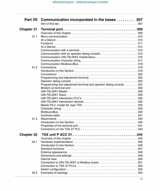
Part VII Communication incorporated in the bases . . . . . . . . . 307Aim of this tab . . . . . . . . . . . . . . . . . . . . . . . . . . . . . . . . . . . . . . . . . . . . . . . . . . 307
Chapter 31 Terminal port. . . . . . . . . . . . . . . . . . . . . . . . . . . . . . . . . . . . . . . 309Overview of this chapter . . . . . . . . . . . . . . . . . . . . . . . . . . . . . . . . . . . . . . . . . . 309
31.1 Micro communication . . . . . . . . . . . . . . . . . . . . . . . . . . . . . . . . . . . . . . . . . . . . 310At a Glance . . . . . . . . . . . . . . . . . . . . . . . . . . . . . . . . . . . . . . . . . . . . . . . . . . . . 310Foreword . . . . . . . . . . . . . . . . . . . . . . . . . . . . . . . . . . . . . . . . . . . . . . . . . . . . . . 311At a Glance . . . . . . . . . . . . . . . . . . . . . . . . . . . . . . . . . . . . . . . . . . . . . . . . . . . . 312Communication with a terminal . . . . . . . . . . . . . . . . . . . . . . . . . . . . . . . . . . . . . 314Communication with an operator dialog console. . . . . . . . . . . . . . . . . . . . . . . . 315Communication UNI-TELWAY master/slave. . . . . . . . . . . . . . . . . . . . . . . . . . . 316Communication character string . . . . . . . . . . . . . . . . . . . . . . . . . . . . . . . . . . . . 317Communication Modbus/JBus. . . . . . . . . . . . . . . . . . . . . . . . . . . . . . . . . . . . . . 318
31.2 Connections . . . . . . . . . . . . . . . . . . . . . . . . . . . . . . . . . . . . . . . . . . . . . . . . . . . 319Introduction to this Section . . . . . . . . . . . . . . . . . . . . . . . . . . . . . . . . . . . . . . . . 319Connections . . . . . . . . . . . . . . . . . . . . . . . . . . . . . . . . . . . . . . . . . . . . . . . . . . . 320Programming and adjustment terminal . . . . . . . . . . . . . . . . . . . . . . . . . . . . . . . 322Operator dialog console . . . . . . . . . . . . . . . . . . . . . . . . . . . . . . . . . . . . . . . . . . 323Programming and adjustment terminal and operator dialog console . . . . . . . . 324Modem on terminal port . . . . . . . . . . . . . . . . . . . . . . . . . . . . . . . . . . . . . . . . . . 326UNI-TELWAY Master . . . . . . . . . . . . . . . . . . . . . . . . . . . . . . . . . . . . . . . . . . . . 328UNI-TELWAY Slave . . . . . . . . . . . . . . . . . . . . . . . . . . . . . . . . . . . . . . . . . . . . . 329UNI-TELWAY intersection PLC’s . . . . . . . . . . . . . . . . . . . . . . . . . . . . . . . . . . . 330UNI-TELWAY intersection devices . . . . . . . . . . . . . . . . . . . . . . . . . . . . . . . . . . 332Master PLC, model 40, type TSX . . . . . . . . . . . . . . . . . . . . . . . . . . . . . . . . . . . 333Character string. . . . . . . . . . . . . . . . . . . . . . . . . . . . . . . . . . . . . . . . . . . . . . . . . 334Modbus/JBus. . . . . . . . . . . . . . . . . . . . . . . . . . . . . . . . . . . . . . . . . . . . . . . . . . . 335Summary table . . . . . . . . . . . . . . . . . . . . . . . . . . . . . . . . . . . . . . . . . . . . . . . . . 337
31.3 Attachments . . . . . . . . . . . . . . . . . . . . . . . . . . . . . . . . . . . . . . . . . . . . . . . . . . . 340Introduction to this Section . . . . . . . . . . . . . . . . . . . . . . . . . . . . . . . . . . . . . . . . 340Properties of the terminal port . . . . . . . . . . . . . . . . . . . . . . . . . . . . . . . . . . . . . . 341Connectors on the TSX 37 PLC . . . . . . . . . . . . . . . . . . . . . . . . . . . . . . . . . . . . 343
Chapter 32 TSX unit P ACC 01 . . . . . . . . . . . . . . . . . . . . . . . . . . . . . . . . . .345Overview of this chapter . . . . . . . . . . . . . . . . . . . . . . . . . . . . . . . . . . . . . . . . . . 345
32.1 Hardware implementation . . . . . . . . . . . . . . . . . . . . . . . . . . . . . . . . . . . . . . . . . 346Introduction to this Section . . . . . . . . . . . . . . . . . . . . . . . . . . . . . . . . . . . . . . . . 346Standard functions . . . . . . . . . . . . . . . . . . . . . . . . . . . . . . . . . . . . . . . . . . . . . . 347External appearance . . . . . . . . . . . . . . . . . . . . . . . . . . . . . . . . . . . . . . . . . . . . . 348Dimensions and settings . . . . . . . . . . . . . . . . . . . . . . . . . . . . . . . . . . . . . . . . . . 349Internal view . . . . . . . . . . . . . . . . . . . . . . . . . . . . . . . . . . . . . . . . . . . . . . . . . . . 350Connection to UNI-TELWAY or Modbus buses . . . . . . . . . . . . . . . . . . . . . . . . 351Connection to TSX 37 PLCs . . . . . . . . . . . . . . . . . . . . . . . . . . . . . . . . . . . . . . . 352Switch configuration . . . . . . . . . . . . . . . . . . . . . . . . . . . . . . . . . . . . . . . . . . . . . 353
32.2 Examples of topology . . . . . . . . . . . . . . . . . . . . . . . . . . . . . . . . . . . . . . . . . . . . 354
11
efesotomasyon - telemecanique inverter
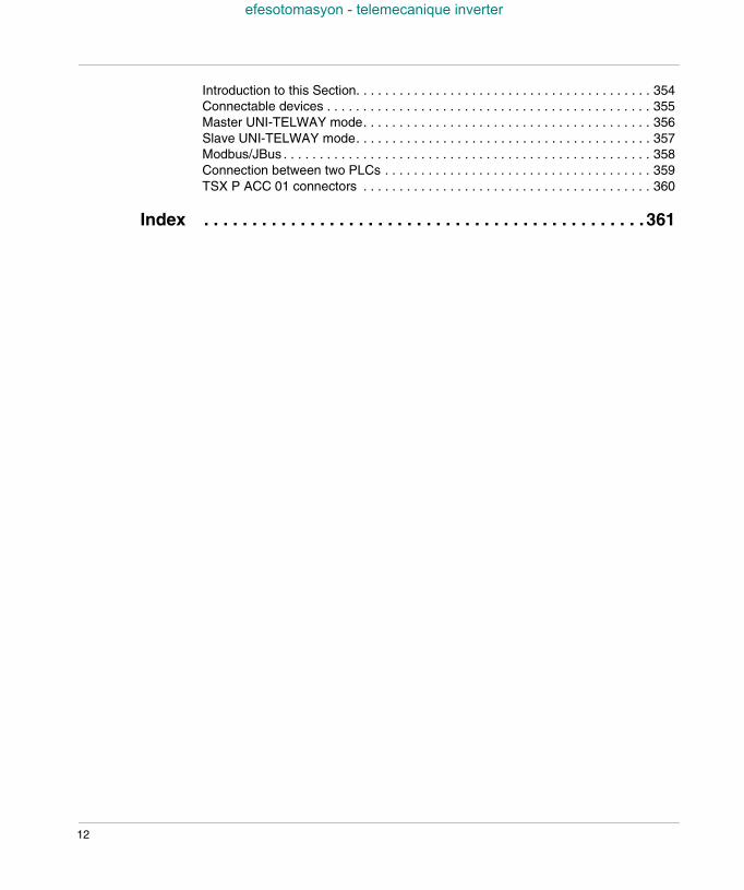
Introduction to this Section. . . . . . . . . . . . . . . . . . . . . . . . . . . . . . . . . . . . . . . . . 354Connectable devices . . . . . . . . . . . . . . . . . . . . . . . . . . . . . . . . . . . . . . . . . . . . . 355Master UNI-TELWAY mode. . . . . . . . . . . . . . . . . . . . . . . . . . . . . . . . . . . . . . . . 356Slave UNI-TELWAY mode. . . . . . . . . . . . . . . . . . . . . . . . . . . . . . . . . . . . . . . . . 357Modbus/JBus . . . . . . . . . . . . . . . . . . . . . . . . . . . . . . . . . . . . . . . . . . . . . . . . . . . 358Connection between two PLCs . . . . . . . . . . . . . . . . . . . . . . . . . . . . . . . . . . . . . 359TSX P ACC 01 connectors . . . . . . . . . . . . . . . . . . . . . . . . . . . . . . . . . . . . . . . . 360
Index . . . . . . . . . . . . . . . . . . . . . . . . . . . . . . . . . . . . . . . . . . . . . . 361
12
efesotomasyon - telemecanique inverter
About the book
At a Glance
Document Scope This manual describes implementation of TSX Micro PLCs.
User Comments We welcome your comments about this document. You can reach us by e-mail [email protected]
TSX DM 37 xxE 13

About the book
efesotomasyon - telemecanique inverter
14 TSX DM 37 xxE
TSX DM 37 xxE
efesotomasyon - telemecanique inverter
I
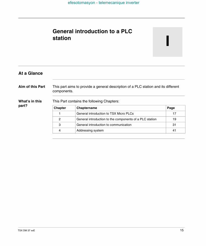
General introduction to a PLCstationAt a Glance
Aim of this Part This part aims to provide a general description of a PLC station and its differentcomponents.
What's in thispart?
This Part contains the following Chapters:
Chapter Chaptername Page
1 General introduction to TSX Micro PLCs 17
2 General introduction to the components of a PLC station 19
3 General introduction to communication 31
4 Addressing system 41
15

General introduction to a PLC station
efesotomasyon - telemecanique inverter
16 TSX DM 37 xxE
TSX DM 37 xxE
efesotomasyon - telemecanique inverter
1
General introduction to TSX MicroPLCsTSX Micro PLCs
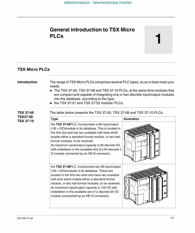
Introduction The range of TSX Micro PLCs comprises several PLC types, so as to best meet yourneeds. The TSX 37-05, TSX 37-08 and TSX 37-10 PLCs, at the same time modules that
are compact and capable of integrating one or two discrete input/output modulesinto the database, according to the type,
the TSX 37-21 and TSX 37-22 modular PLCs.
TSX 37-05TSX37-08TSX 37-10
The table below presents the TSX 37-05, TSX 37-08 and TSX 37-10 PLCs.
Type Illustration
the TSX 37-05PLC, incorporates a 28 input/output(16I +12O)module in its database. This is located inthe first slot and has two available half slots whichenable either a standard format module, or two half-format modules, to be received.Its maximum input/output capacity is 92 discrete I/O,with installation in the available slot of a 64 discrete I/O module connected by an HE10 connector.
the TSX 37-08PLC, incorporates two 28 input/output(16I +12O)modules in its database. These arelocated in the first two slots and have two availablehalf slots which enable either a standard formatmodule, or two half-format modules, to be received.Its maximum input/output capacity is 120 I/O withinstallation in the available slot of a discrete 64 I/Omodule (connected by an HE10 connector).
17
General introduction to TSX Micro PLCs
efesotomasyon - telemecanique inverter
TSX 37-21TSX37-22
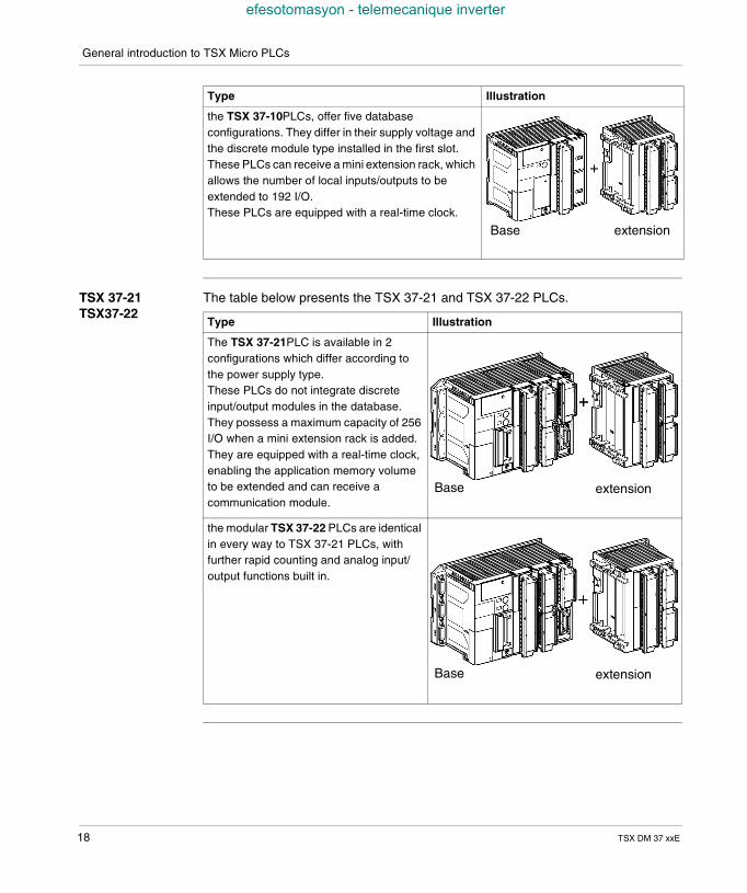
The table below presents the TSX 37-21 and TSX 37-22 PLCs.
the TSX 37-10PLCs, offer five databaseconfigurations. They differ in their supply voltage andthe discrete module type installed in the first slot.These PLCs can receive a mini extension rack, whichallows the number of local inputs/outputs to beextended to 192 I/O.These PLCs are equipped with a real-time clock.
Type Illustration
Base extension
Type Illustration
The TSX 37-21PLC is available in 2configurations which differ according tothe power supply type.These PLCs do not integrate discreteinput/output modules in the database.They possess a maximum capacity of 256I/O when a mini extension rack is added.They are equipped with a real-time clock,enabling the application memory volumeto be extended and can receive acommunication module.
the modular TSX 37-22 PLCs are identicalin every way to TSX 37-21 PLCs, withfurther rapid counting and analog input/output functions built in.
Base extension
Base extension
18 TSX DM 37 xxE
TSX DM 37 xxE
efesotomasyon - telemecanique inverter
2
General introduction to thecomponents of a PLC stationAt a Glance
Aim of thisChapter
This chapter aims to describe the main constituent elements of a TSX 37 PLC.
What's in thisChapter?
This Chapter contains the following Maps:
Topic Page
General information about discrete inputs/outputs 20
Local discrete inputs/outputs in the rack 21
Remote discrete inputs/outputs 22
Discrete safety inputs/outputs 24
Local analog inputs/outputs 25
Remote analog inputs/outputs 27
Counting channel 28
Forced PLC ventilation 30
19
General introduction of the components of a PLC station
efesotomasyon - telemecanique inverter
General information about discrete inputs/outputs
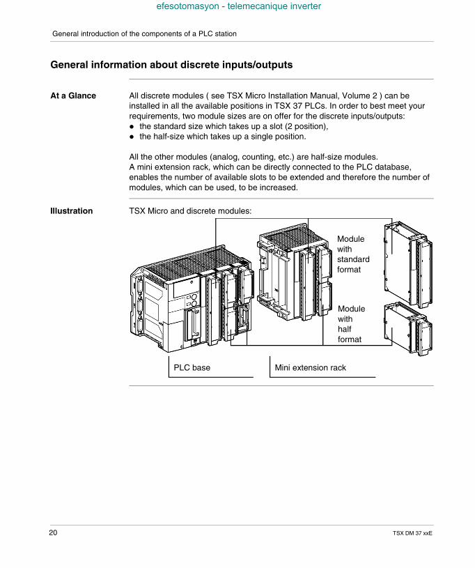
At a Glance All discrete modules ( see TSX Micro Installation Manual, Volume 2 ) can beinstalled in all the available positions in TSX 37 PLCs. In order to best meet yourrequirements, two module sizes are on offer for the discrete inputs/outputs: the standard size which takes up a slot (2 position), the half-size which takes up a single position.
All the other modules (analog, counting, etc.) are half-size modules.A mini extension rack, which can be directly connected to the PLC database,enables the number of available slots to be extended and therefore the number ofmodules, which can be used, to be increased.
Illustration TSX Micro and discrete modules:
PLC base Mini extension rack
Modulewithstandardformat
Modulewithhalfformat
20 TSX DM 37 xxE
General introduction of the components of a PLC station
efesotomasyon - telemecanique inverter
Local discrete inputs/outputs in the rack
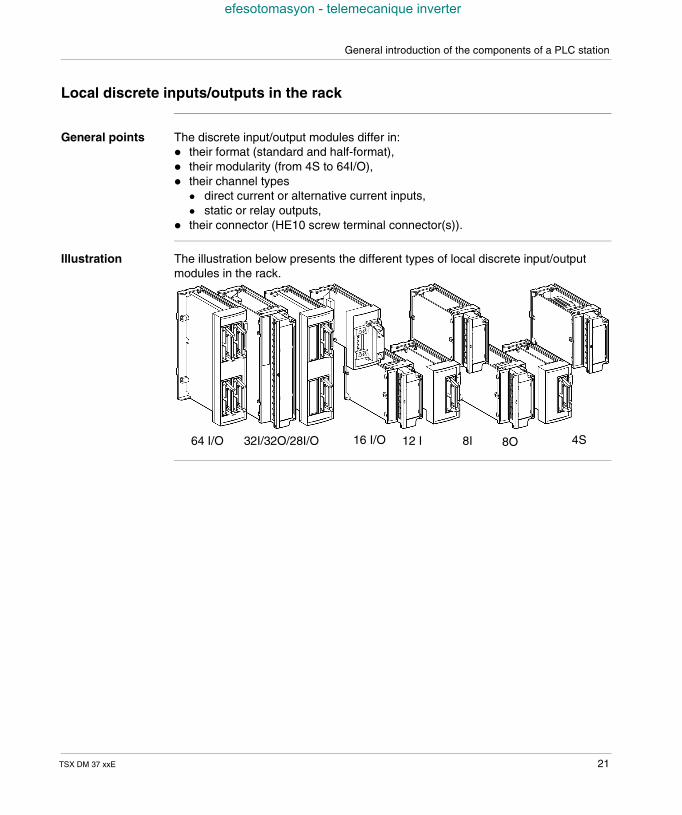
General points The discrete input/output modules differ in: their format (standard and half-format), their modularity (from 4S to 64I/O), their channel types
direct current or alternative current inputs, static or relay outputs,
their connector (HE10 screw terminal connector(s)).
Illustration The illustration below presents the different types of local discrete input/outputmodules in the rack.
64 I/O 32I/32O/28I/O 16 I/O 12 I 8I 8O 4S
TSX DM 37 xxE 21
General introduction of the components of a PLC station
efesotomasyon - telemecanique inverter
Remote discrete inputs/outputs
Introduction The TSX Micro range enables you to use remote discrete inputs/outputs (seeImplementation manual TSX Micro Volume 2)
For this, two modules are proposed: an offset module TSX STZ 10, a bus master module AS-i TSX SAZ 10 (only on TSX 37-10 and TSX 37-21/22).
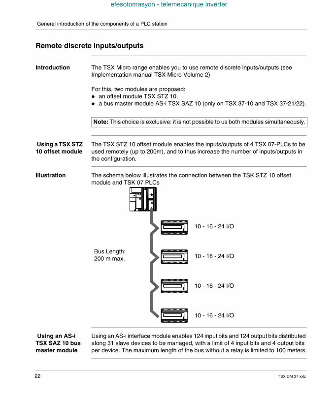
Using a TSX STZ10 offset module
The TSX STZ 10 offset module enables the inputs/outputs of 4 TSX 07-PLCs to beused remotely (up to 200m), and to thus increase the number of inputs/outputs inthe configuration.
Illustration The schema below illustrates the connection between the TSK STZ 10 offsetmodule and TSK 07 PLCs
Using an AS-iTSX SAZ 10 busmaster module
Using an AS-i interface module enables 124 input bits and 124 output bits distributedalong 31 slave devices to be managed, with a limit of 4 input bits and 4 output bitsper device. The maximum length of the bus without a relay is limited to 100 meters.
Note: This choice is exclusive: it is not possible to us both modules simultaneously.
10 - 16 - 24 I/O
10 - 16 - 24 I/O
10 - 16 - 24 I/O
10 - 16 - 24 I/O
Bus Length:200 m max.
22 TSX DM 37 xxE
General introduction of the components of a PLC station
efesotomasyon - telemecanique inverter
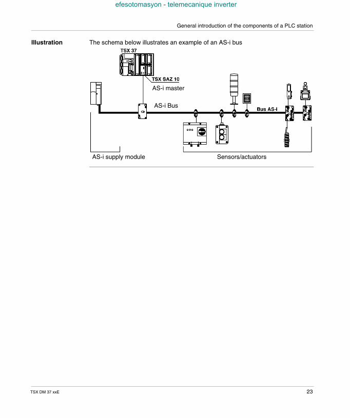
Illustration The schema below illustrates an example of an AS-i bus
Sensors/actuators
AS-i master
AS-i supply module
AS-i Bus
TSX DM 37 xxE 23
General introduction of the components of a PLC station
efesotomasyon - telemecanique inverter
Discrete safety inputs/outputs
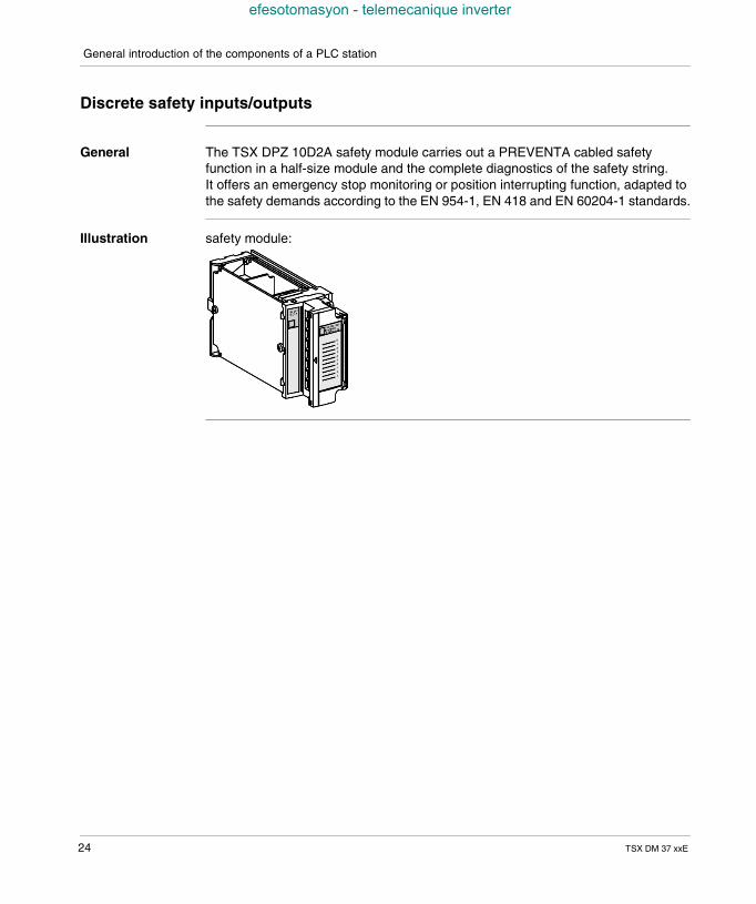
General The TSX DPZ 10D2A safety module carries out a PREVENTA cabled safetyfunction in a half-size module and the complete diagnostics of the safety string.It offers an emergency stop monitoring or position interrupting function, adapted tothe safety demands according to the EN 954-1, EN 418 and EN 60204-1 standards.
Illustration safety module:
24 TSX DM 37 xxE
General introduction of the components of a PLC station
efesotomasyon - telemecanique inverter
Local analog inputs/outputs
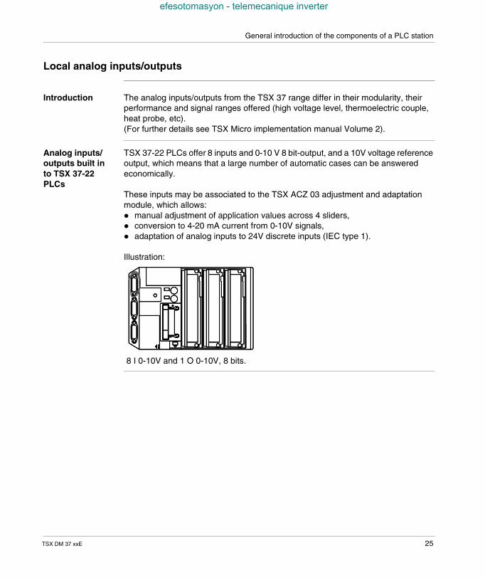
Introduction The analog inputs/outputs from the TSX 37 range differ in their modularity, theirperformance and signal ranges offered (high voltage level, thermoelectric couple,heat probe, etc).(For further details see TSX Micro implementation manual Volume 2).
Analog inputs/outputs built into TSX 37-22PLCs
TSX 37-22 PLCs offer 8 inputs and 0-10 V 8 bit-output, and a 10V voltage referenceoutput, which means that a large number of automatic cases can be answeredeconomically.
These inputs may be associated to the TSX ACZ 03 adjustment and adaptationmodule, which allows: manual adjustment of application values across 4 sliders, conversion to 4-20 mA current from 0-10V signals, adaptation of analog inputs to 24V discrete inputs (IEC type 1).
Illustration:
8 I 0-10V and 1 O 0-10V, 8 bits.
TSX DM 37 xxE 25
General introduction of the components of a PLC station
efesotomasyon - telemecanique inverter
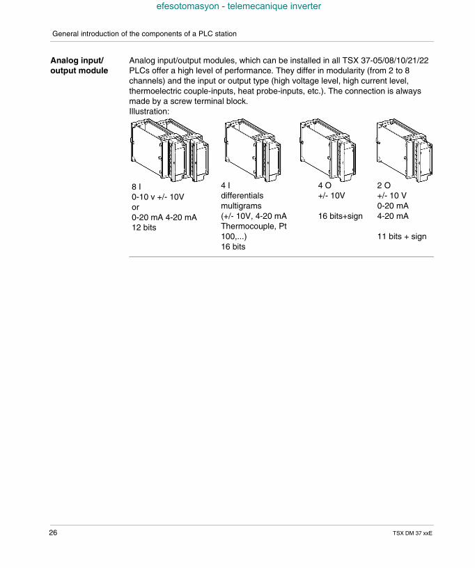
Analog input/output module
Analog input/output modules, which can be installed in all TSX 37-05/08/10/21/22PLCs offer a high level of performance. They differ in modularity (from 2 to 8channels) and the input or output type (high voltage level, high current level,thermoelectric couple-inputs, heat probe-inputs, etc.). The connection is alwaysmade by a screw terminal block.Illustration:
8 I0-10 v +/- 10Vor0-20 mA 4-20 mA12 bits
4 Idifferentialsmultigrams(+/- 10V, 4-20 mAThermocouple, Pt100,...)16 bits
4 O+/- 10V
16 bits+sign
2 O+/- 10 V0-20 mA4-20 mA
11 bits + sign
26 TSX DM 37 xxE
General introduction of the components of a PLC station
efesotomasyon - telemecanique inverter
Remote analog inputs/outputs
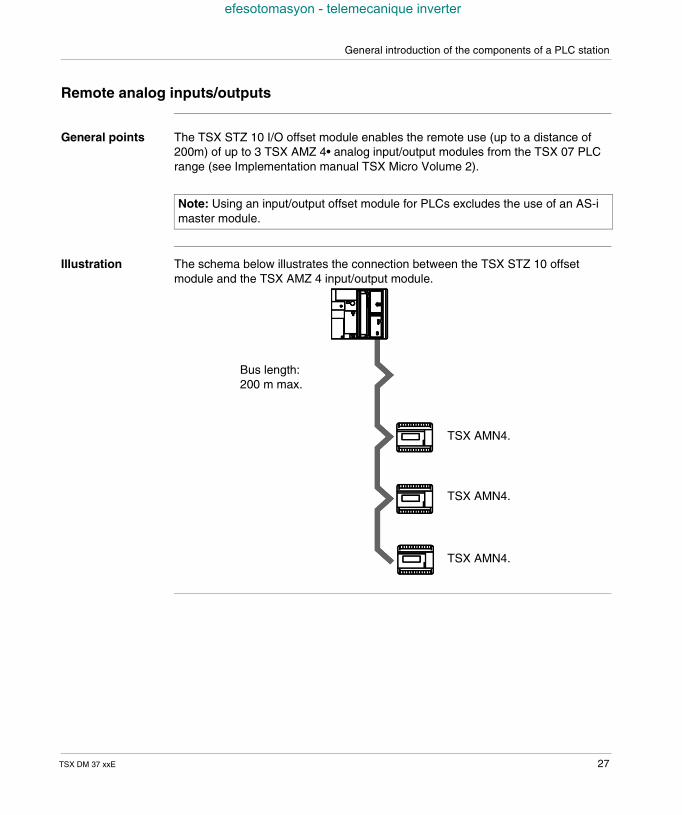
General points The TSX STZ 10 I/O offset module enables the remote use (up to a distance of200m) of up to 3 TSX AMZ 4• analog input/output modules from the TSX 07 PLCrange (see Implementation manual TSX Micro Volume 2).
Illustration The schema below illustrates the connection between the TSX STZ 10 offsetmodule and the TSX AMZ 4 input/output module.
Note: Using an input/output offset module for PLCs excludes the use of an AS-imaster module.
TSX AMN4.
TSX AMN4.
TSX AMN4.
Bus length:200 m max.
TSX DM 37 xxE 27
General introduction of the components of a PLC station
efesotomasyon - telemecanique inverter
Counting channel
Introduction TSX 37 PLCs offer 3 possibilities for counting: via the first four discrete inputs of the first module, by using the counting channels which are built in to TSX 37-22 PLCs, via counting modules, which can be installed in the available positions (TSX CTZ
1A/2A, TSX CTZ 2AA).
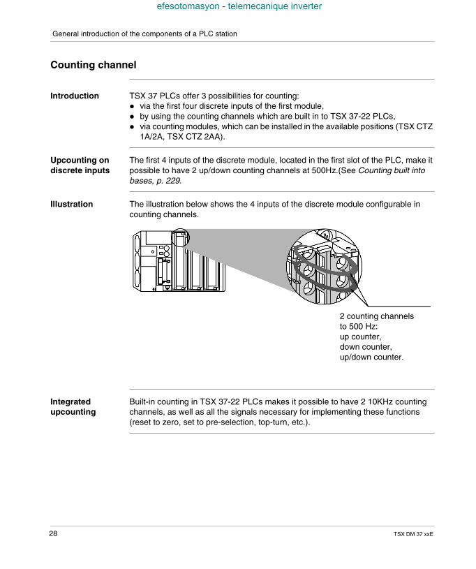
Upcounting ondiscrete inputs
The first 4 inputs of the discrete module, located in the first slot of the PLC, make itpossible to have 2 up/down counting channels at 500Hz.(See Counting built intobases, p. 229.
Illustration The illustration below shows the 4 inputs of the discrete module configurable incounting channels.
Integratedupcounting
Built-in counting in TSX 37-22 PLCs makes it possible to have 2 10KHz countingchannels, as well as all the signals necessary for implementing these functions(reset to zero, set to pre-selection, top-turn, etc.).
2 counting channelsto 500 Hz:up counter,down counter,up/down counter.
28 TSX DM 37 xxE
General introduction of the components of a PLC station
efesotomasyon - telemecanique inverter
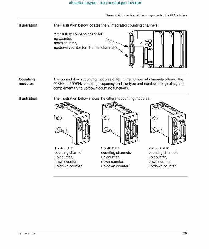
Illustration The illustration below locates the 2 integrated counting channels.
Countingmodules
The up and down counting modules differ in the number of channels offered, the40KHz or 500KHz counting frequency and the type and number of logical signalscomplementary to up/down counting functions.
Illustration The illustration below shows the different counting modules.
2 x 10 KHz counting channels:up counter,down counter,up/down counter (on the first channel).
1 x 40 KHzcounting channelup counter,down counter,up/down counter.
2 x 40 KHzcounting channelsup counter,down counter,up/down counter.
2 x 500 KHzcounting channelsup counter,down counter,up/down counter.
TSX DM 37 xxE 29
General introduction of the components of a PLC station
efesotomasyon - telemecanique inverter
Forced PLC ventilation
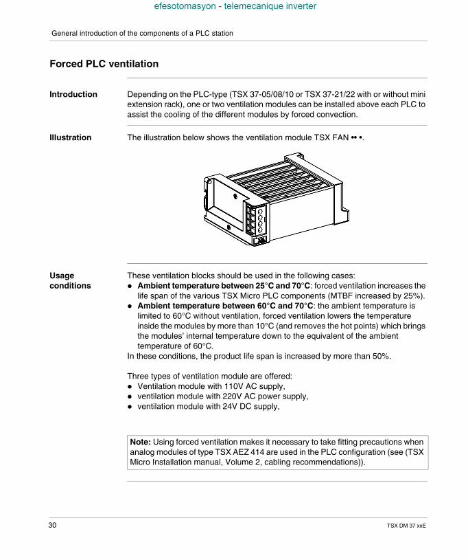
Introduction Depending on the PLC-type (TSX 37-05/08/10 or TSX 37-21/22 with or without miniextension rack), one or two ventilation modules can be installed above each PLC toassist the cooling of the different modules by forced convection.
Illustration The illustration below shows the ventilation module TSX FAN •• •.
Usageconditions
These ventilation blocks should be used in the following cases: Ambient temperature between 25°C and 70°C: forced ventilation increases the
life span of the various TSX Micro PLC components (MTBF increased by 25%). Ambient temperature between 60°C and 70°C: the ambient temperature is
limited to 60°C without ventilation, forced ventilation lowers the temperatureinside the modules by more than 10°C (and removes the hot points) which bringsthe modules’ internal temperature down to the equivalent of the ambienttemperature of 60°C.
In these conditions, the product life span is increased by more than 50%.
Three types of ventilation module are offered: Ventilation module with 110V AC supply, ventilation module with 220V AC power supply, ventilation module with 24V DC supply,
Note: Using forced ventilation makes it necessary to take fitting precautions whenanalog modules of type TSX AEZ 414 are used in the PLC configuration (see (TSXMicro Installation manual, Volume 2, cabling recommendations)).
30 TSX DM 37 xxE
TSX DM 37 xxE
efesotomasyon - telemecanique inverter
3
General introduction tocommunicationAt a Glance
Aim of thisChapter
This chapter aims to provide a general description of communication with TSX MicroPLCs.
What's in thisChapter?
This Chapter contains the following Maps:
Topic Page
Communication 32
UNI-TELWAY link 33
Character mode link by terminal port 34
Modbus Connection 35
FIPWAY link 36
FIPIO link 37
Modem link 38
Modbus Plus Link 39
31
General introduction to communication
efesotomasyon - telemecanique inverter
Communication
General TSX 37 PLCs offer a series of economic multidrop links via the terminal port of allthe PLCs and an additional permanent connection for the operator dialog on TSX37-21/22 PLCs.These connections enable the connection of (one single protocol at a time): a programming terminal and/or an operator dialog device (UNITELWAY master
mode), the PLC to an UNI-TELWAY multidrop link (UNI-TELWAY master or slave mode), the PLC to the Modbus bus, a printer or a terminal in character mode, a modem.
A TSX P ACC 01 enables the PLC to be connected to a UNI-TELWAY link, whenthe distance between the devices is greater than 10 meters. If desired, it makes itpossible to duplicate the terminal port in order to simultaneously connect a consoleand an operator dialog device on a TSX 37 05/08/10 PLC.
TSX 37-21 and TSX 37-22 PLCs are also fitted with a slot which makes it possibleto receive a communication module in PCMCIA format (full-duplex or half-duplex,UNI-TELWAY, JBUS/MODBUS, FIPWAY, FIPIO Agent, Modbus+, modemasynchronous series of links).
32 TSX DM 37 xxE
General introduction to communication
efesotomasyon - telemecanique inverter
UNI-TELWAY link
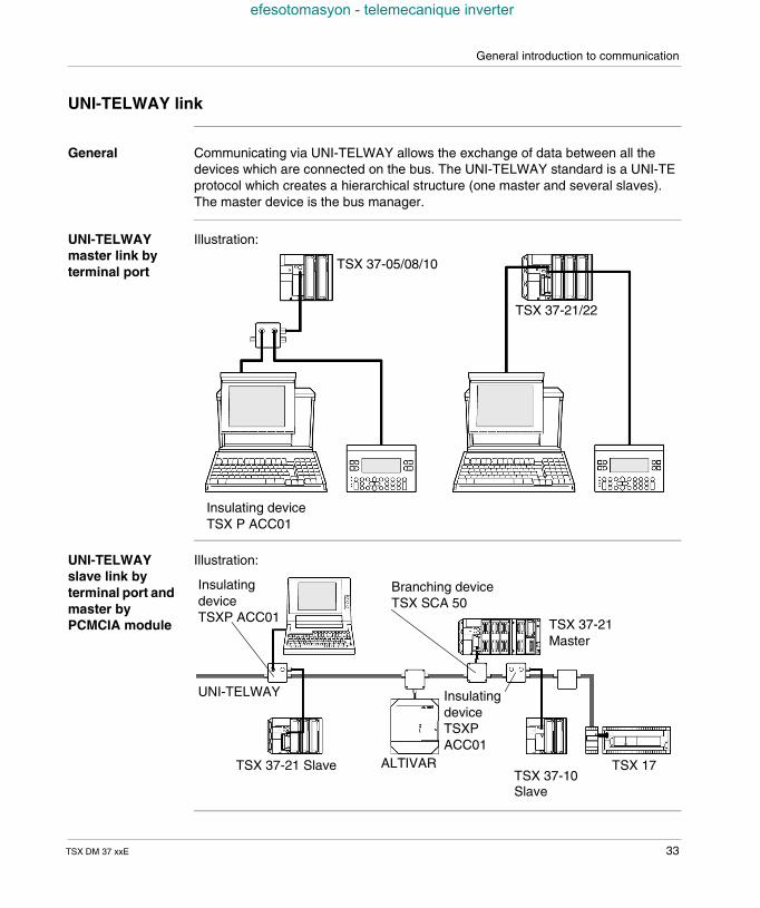
General Communicating via UNI-TELWAY allows the exchange of data between all thedevices which are connected on the bus. The UNI-TELWAY standard is a UNI-TEprotocol which creates a hierarchical structure (one master and several slaves).The master device is the bus manager.
UNI-TELWAYmaster link byterminal port
Illustration:
UNI-TELWAYslave link byterminal port andmaster byPCMCIA module
Illustration:
TSX 37-05/08/10
TSX 37-21/22
Insulating deviceTSX P ACC01
Branching deviceTSX SCA 50
TSX 37-21Master
InsulatingdeviceTSXPACC01
ALTIVARTSX 37-21 Slave TSX 17
UNI-TELWAY
InsulatingdeviceTSXP ACC01
TSX 37-10Slave
TSX DM 37 xxE 33
General introduction to communication
efesotomasyon - telemecanique inverter
Character mode link by terminal port
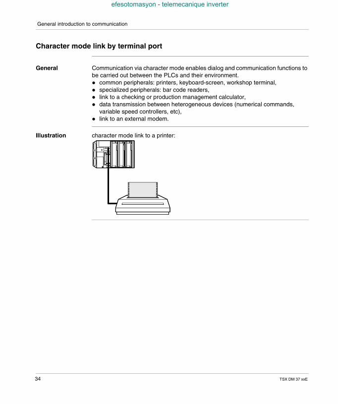
General Communication via character mode enables dialog and communication functions tobe carried out between the PLCs and their environment. common peripherals: printers, keyboard-screen, workshop terminal, specialized peripherals: bar code readers, link to a checking or production management calculator, data transmission between heterogeneous devices (numerical commands,
variable speed controllers, etc), link to an external modem.
Illustration character mode link to a printer:
34 TSX DM 37 xxE
General introduction to communication
efesotomasyon - telemecanique inverter
Modbus Connection
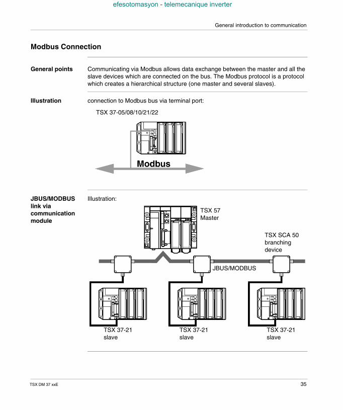
General points Communicating via Modbus allows data exchange between the master and all theslave devices which are connected on the bus. The Modbus protocol is a protocolwhich creates a hierarchical structure (one master and several slaves).
Illustration connection to Modbus bus via terminal port:
JBUS/MODBUSlink viacommunicationmodule
Illustration:
TSX 37-05/08/10/21/22
TSX 57Master
TSX SCA 50branchingdevice
JBUS/MODBUS
TSX 37-21slave
TSX 37-21slave
TSX 37-21slave
TSX DM 37 xxE 35
General introduction to communication
efesotomasyon - telemecanique inverter
FIPWAY link
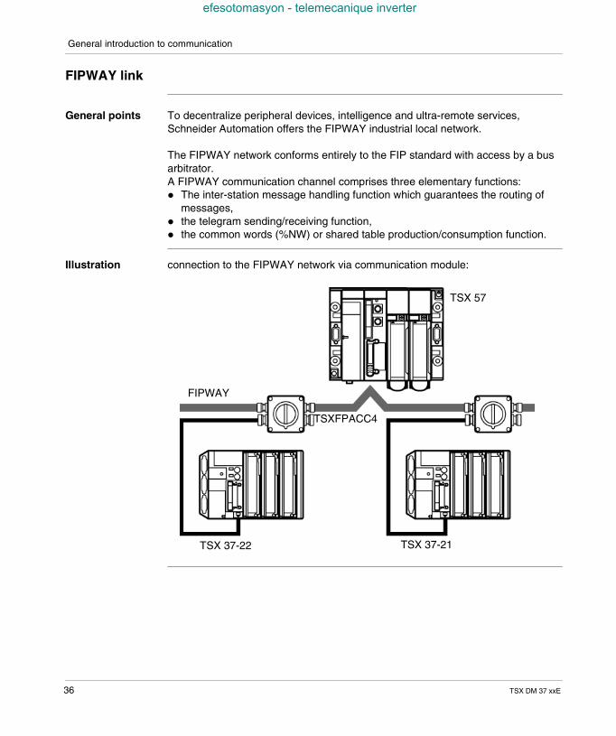
General points To decentralize peripheral devices, intelligence and ultra-remote services,Schneider Automation offers the FIPWAY industrial local network.
The FIPWAY network conforms entirely to the FIP standard with access by a busarbitrator.A FIPWAY communication channel comprises three elementary functions: The inter-station message handling function which guarantees the routing of
messages, the telegram sending/receiving function, the common words (%NW) or shared table production/consumption function.
Illustration connection to the FIPWAY network via communication module:
TSX 57
FIPWAY
TSXFPACC4
TSX 37-22 TSX 37-21
36 TSX DM 37 xxE
General introduction to communication
efesotomasyon - telemecanique inverter
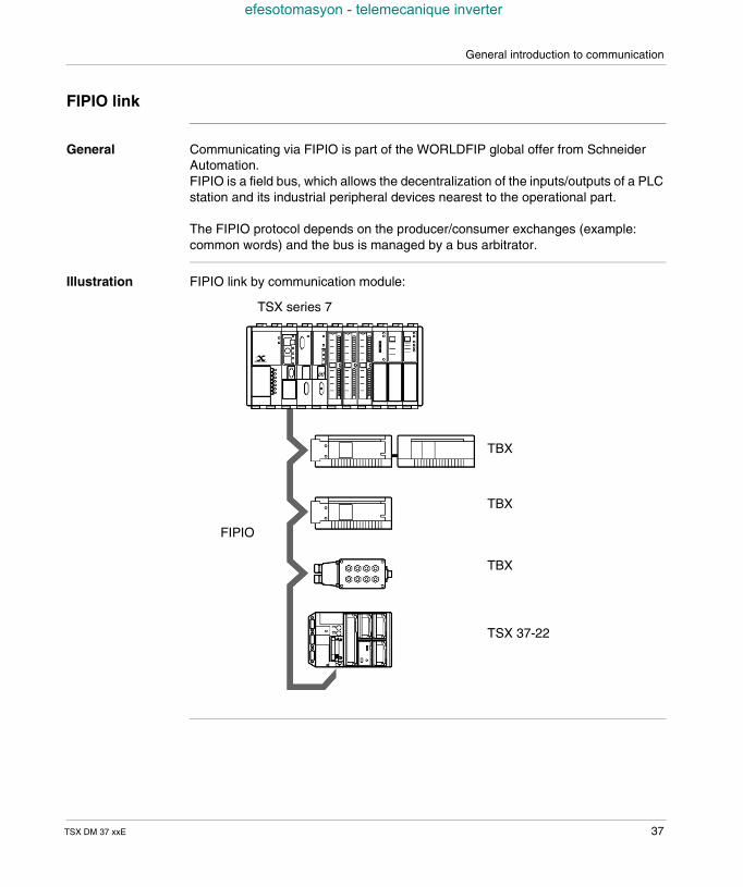
FIPIO link
General Communicating via FIPIO is part of the WORLDFIP global offer from SchneiderAutomation.FIPIO is a field bus, which allows the decentralization of the inputs/outputs of a PLCstation and its industrial peripheral devices nearest to the operational part.
The FIPIO protocol depends on the producer/consumer exchanges (example:common words) and the bus is managed by a bus arbitrator.
Illustration FIPIO link by communication module:
TSX series 7
TBX
TBX
TBX
TSX 37-22
FIPIO
TSX DM 37 xxE 37
General introduction to communication
efesotomasyon - telemecanique inverter
Modem link
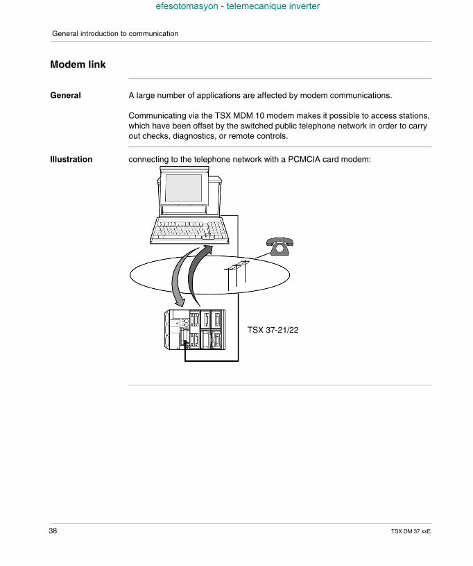
General A large number of applications are affected by modem communications.
Communicating via the TSX MDM 10 modem makes it possible to access stations,which have been offset by the switched public telephone network in order to carryout checks, diagnostics, or remote controls.
Illustration connecting to the telephone network with a PCMCIA card modem:
TSX 37-21/22
38 TSX DM 37 xxE
General introduction to communication
efesotomasyon - telemecanique inverter
Modbus Plus Link
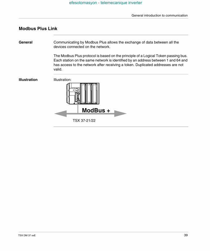
General Communicating by Modbus Plus allows the exchange of data between all thedevices connected on the network.
The Modbus Plus protocol is based on the principle of a Logical Token passing bus.Each station on the same network is identified by an address between 1 and 64 andhas access to the network after receiving a token. Duplicated addresses are notvalid.
Illustration Illustration:
TSX 37-21/22
TSX DM 37 xxE 39

General introduction to communication
efesotomasyon - telemecanique inverter
40 TSX DM 37 xxE
TSX DM 37 xxE
efesotomasyon - telemecanique inverter
4
Addressing systemChannel address settings
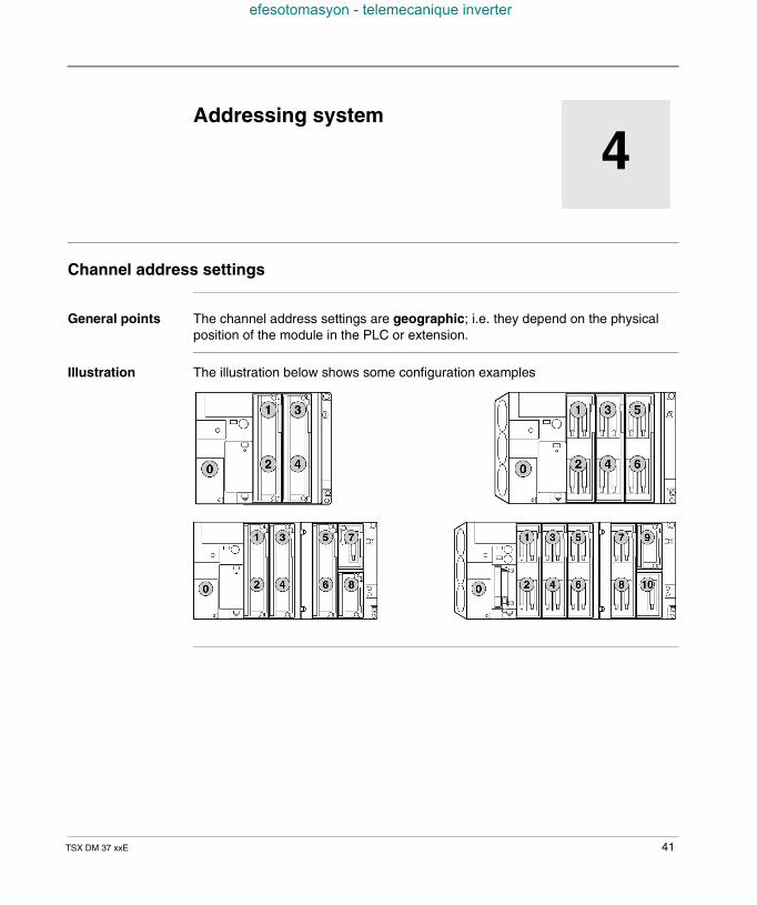
General points The channel address settings are geographic; i.e. they depend on the physicalposition of the module in the PLC or extension.
Illustration The illustration below shows some configuration examples
41
Addressing system
efesotomasyon - telemecanique inverter
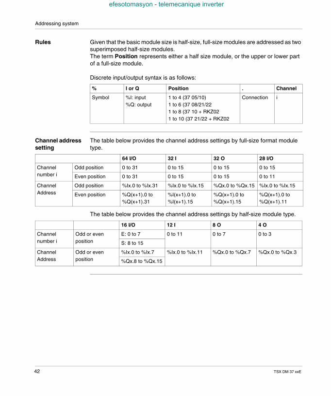
Rules Given that the basic module size is half-size, full-size modules are addressed as twosuperimposed half-size modules.The term Position represents either a half size module, or the upper or lower partof a full-size module.
Discrete input/output syntax is as follows:
Channel addresssetting
The table below provides the channel address settings by full-size format moduletype.
The table below provides the channel address settings by half-size module type.
% I or Q Position . Channel
Symbol %I: input%Q: output
1 to 4 (37 05/10)1 to 6 (37 08/21/221 to 8 (37 10 + RKZ021 to 10 (37 21/22 + RKZ02
Connection i
64 I/O 32 I 32 O 28 I/O
Channelnumber i
Odd position 0 to 31 0 to 15 0 to 15 0 to 15
Even position 0 to 31 0 to 15 0 to 15 0 to 11
ChannelAddress
Odd position %Ix.0 to %Ix.31 %Ix.0 to %Ix.15 %Qx.0 to %Qx.15 %Ix.0 to %Ix.15
Even position %Q(x+1).0 to%Q(x+1).31
%I(x+1).0 to%I(x+1).15
%Q(x+1).0 to%Q(x+1).15
%Q(x+1).0 to%Q(x+1).11
16 I/O 12 I 8 O 4 O
Channelnumber i
Odd or evenposition
E: 0 to 7 0 to 11 0 to 7 0 to 3
S: 8 to 15
ChannelAddress
Odd or evenposition
%Ix.0 to %Ix.7 %Ix.0 to %Ix.11 %Qx.0 to %Qx.7 %Qx.0 to %Qx.3
%Qx.8 to %Qx.15
42 TSX DM 37 xxE
TSX DM 37 xxE
efesotomasyon - telemecanique inverter
II
TSX 37 PLCAt a Glance
Aim of this Part This part is about the TSX 37-05, TSX 37-08, TSX 37-10 and TSX 37- 21/22 PLCs.
What's in thispart?
This Part contains the following Chapters:
Chapter Chaptername Page
5 TSX 37-05 PLC 45
6 TSX 37-08PLC 51
7 TSX 37-10PLC 57
8 TSX 37-21 and TSX 37-22 PLCs 63
9 TSX 37 PLC supplies 71
10 Memories on TSX 37 75
11 Mini extention rack 81
12 TSX 37 PLC performance 85
13 Commissioning standards and conditions 87
43

TSX 37 PLC
efesotomasyon - telemecanique inverter
44 TSX DM 37 xxE
TSX DM 37 xxE
efesotomasyon - telemecanique inverter
5
TSX 37-05 PLCAt a Glance
Aim of thisChapter
This chapter is about the TSX 37-05 PLC, its physical description and its technicalcharacteristics.
What's in thisChapter?
This Chapter contains the following Maps:
Topic Page
Introduction to the TSX 37 05 PLC base 46
TSX 37-05: physical description 48
Characteristics of the TSX 37-05 49
Display panel on TSX 37-05 50
45
TSX 37-05 PLC
efesotomasyon - telemecanique inverter
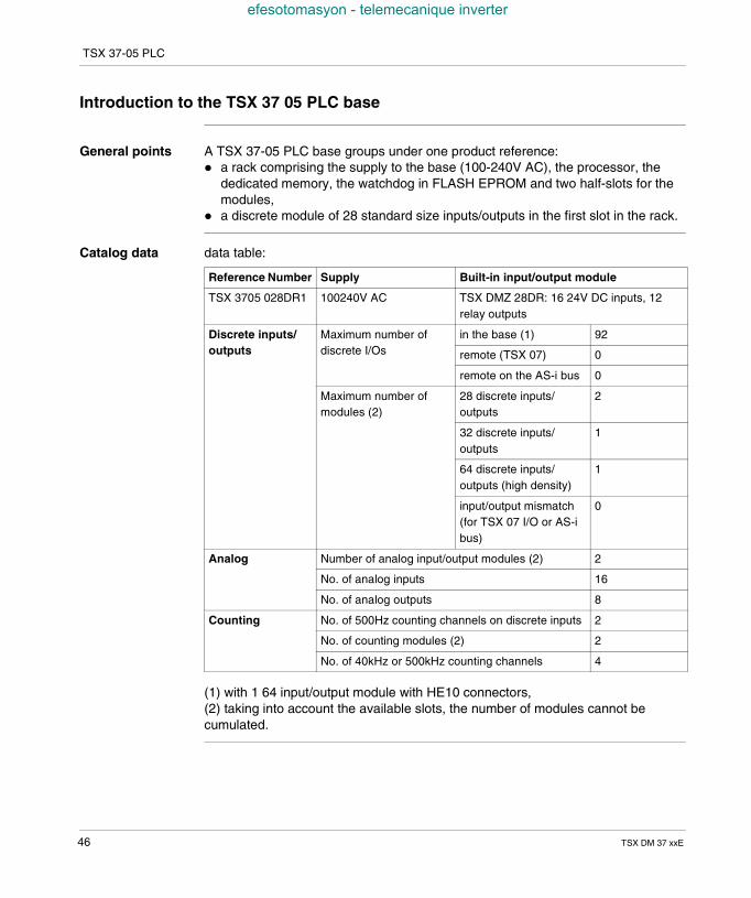
Introduction to the TSX 37 05 PLC base
General points A TSX 37-05 PLC base groups under one product reference: a rack comprising the supply to the base (100-240V AC), the processor, the
dedicated memory, the watchdog in FLASH EPROM and two half-slots for themodules,
a discrete module of 28 standard size inputs/outputs in the first slot in the rack.
Catalog data data table:
(1) with 1 64 input/output module with HE10 connectors,(2) taking into account the available slots, the number of modules cannot becumulated.
Reference Number Supply Built-in input/output module
TSX 3705 028DR1 100240V AC TSX DMZ 28DR: 16 24V DC inputs, 12relay outputs
Discrete inputs/outputs
Maximum number ofdiscrete I/Os
in the base (1) 92
remote (TSX 07) 0
remote on the AS-i bus 0
Maximum number ofmodules (2)
28 discrete inputs/outputs
2
32 discrete inputs/outputs
1
64 discrete inputs/outputs (high density)
1
input/output mismatch(for TSX 07 I/O or AS-ibus)
0
Analog Number of analog input/output modules (2) 2
No. of analog inputs 16
No. of analog outputs 8
Counting No. of 500Hz counting channels on discrete inputs 2
No. of counting modules (2) 2
No. of 40kHz or 500kHz counting channels 4
46 TSX DM 37 xxE

TSX 37-05 PLC
efesotomasyon - telemecanique inverter
RS 485 terminalport
With an 8-point mini-DIN size RS 485 terminal port, it is possible to: connect an FTX type terminal or a compatible PC, a printer, and to connect the PLC to the UNI-TELWAY or Modbus busses. For this, it
proposes, by default, the UNI-TELWAY 96 Baud master communication modeand, by configuration: the UNI-TELWAY slave mode or, ASCII character mode or, the Modbus protocol.
Note: The terminal and PLC can both be connected to the UNI-TELWAY bus usingthe TSX P ACC 01 insulating device. This should be used when the distancebetween the UNI-TELWAY connection equipment is greater than 10 meters (seeTSX unit P ACC 01, p. 345).
TSX DM 37 xxE 47
TSX 37-05 PLC
efesotomasyon - telemecanique inverter
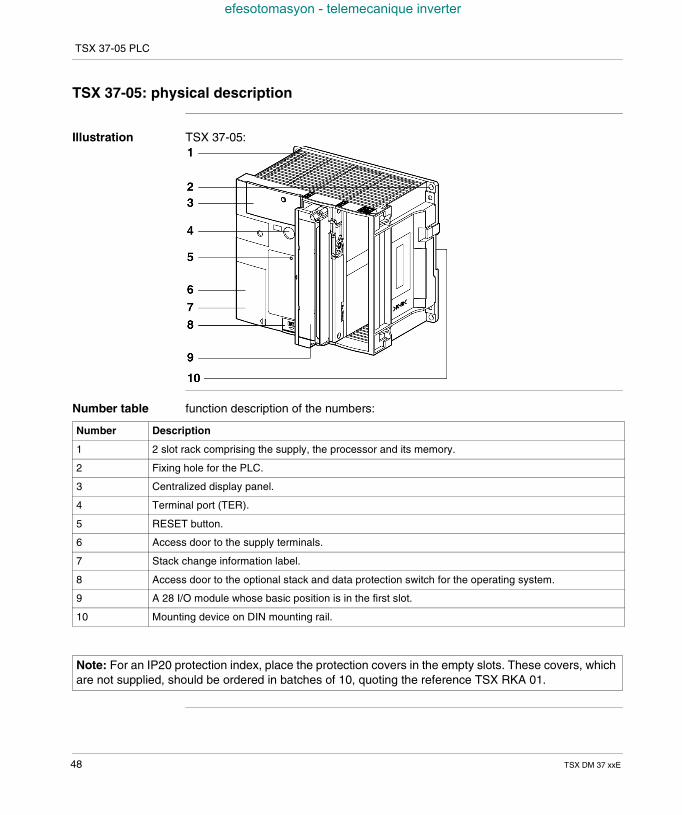
TSX 37-05: physical description
Illustration TSX 37-05:
Number table function description of the numbers:
Number Description
1 2 slot rack comprising the supply, the processor and its memory.
2 Fixing hole for the PLC.
3 Centralized display panel.
4 Terminal port (TER).
5 RESET button.
6 Access door to the supply terminals.
7 Stack change information label.
8 Access door to the optional stack and data protection switch for the operating system.
9 A 28 I/O module whose basic position is in the first slot.
10 Mounting device on DIN mounting rail.
Note: For an IP20 protection index, place the protection covers in the empty slots. These covers, whichare not supplied, should be ordered in batches of 10, quoting the reference TSX RKA 01.
48 TSX DM 37 xxE
TSX 37-05 PLC
efesotomasyon - telemecanique inverter
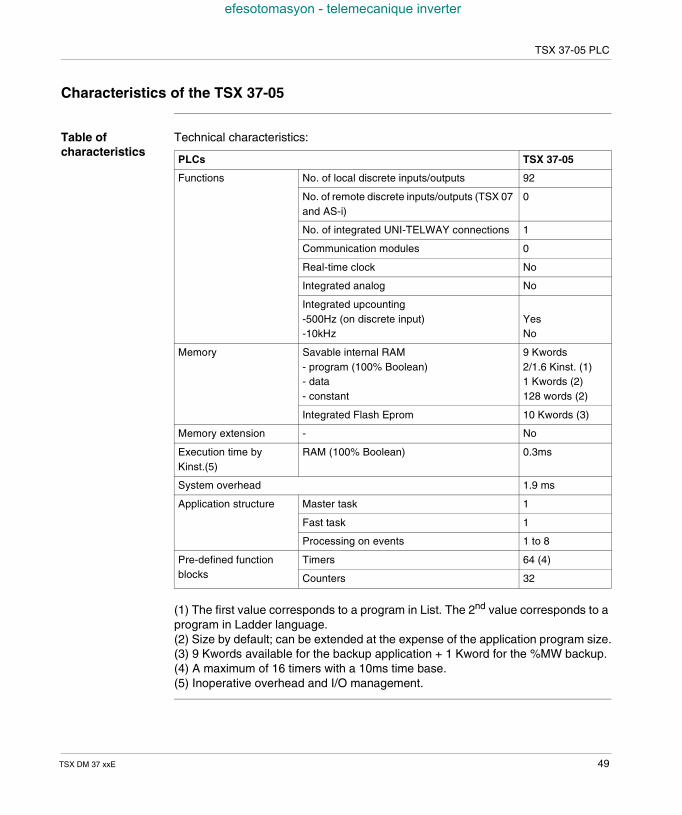
Characteristics of the TSX 37-05
Table ofcharacteristics
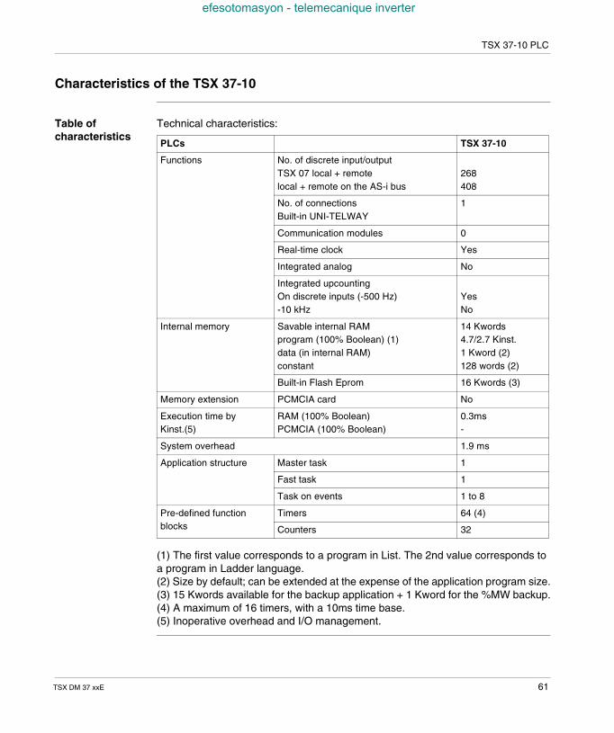
Technical characteristics:
(1) The first value corresponds to a program in List. The 2nd value corresponds to aprogram in Ladder language.(2) Size by default; can be extended at the expense of the application program size.(3) 9 Kwords available for the backup application + 1 Kword for the %MW backup.(4) A maximum of 16 timers with a 10ms time base.(5) Inoperative overhead and I/O management.
PLCs TSX 37-05
Functions No. of local discrete inputs/outputs 92
No. of remote discrete inputs/outputs (TSX 07and AS-i)
0
No. of integrated UNI-TELWAY connections 1
Communication modules 0
Real-time clock No
Integrated analog No
Integrated upcounting-500Hz (on discrete input)-10kHz
YesNo
Memory Savable internal RAM- program (100% Boolean)- data- constant
9 Kwords2/1.6 Kinst. (1)1 Kwords (2)128 words (2)
Integrated Flash Eprom 10 Kwords (3)
Memory extension - No
Execution time byKinst.(5)
RAM (100% Boolean) 0.3ms
System overhead 1.9 ms
Application structure Master task 1
Fast task 1
Processing on events 1 to 8
Pre-defined functionblocks
Timers 64 (4)
Counters 32
TSX DM 37 xxE 49
TSX 37-05 PLC
efesotomasyon - telemecanique inverter
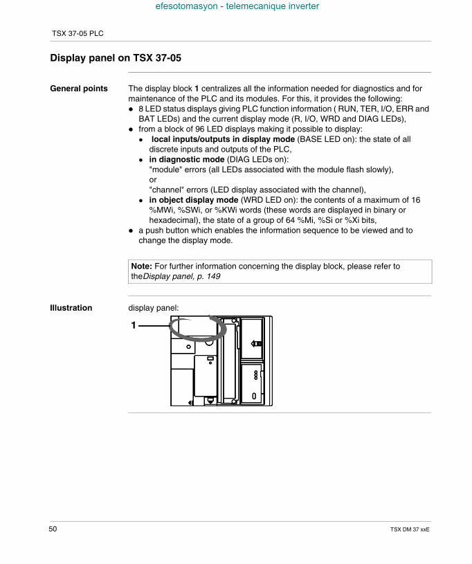
Display panel on TSX 37-05
General points The display block 1 centralizes all the information needed for diagnostics and formaintenance of the PLC and its modules. For this, it provides the following: 8 LED status displays giving PLC function information ( RUN, TER, I/O, ERR and
BAT LEDs) and the current display mode (R, I/O, WRD and DIAG LEDs), from a block of 96 LED displays making it possible to display:
local inputs/outputs in display mode (BASE LED on): the state of alldiscrete inputs and outputs of the PLC,
in diagnostic mode (DIAG LEDs on):"module" errors (all LEDs associated with the module flash slowly),or"channel" errors (LED display associated with the channel),
in object display mode (WRD LED on): the contents of a maximum of 16%MWi, %SWi, or %KWi words (these words are displayed in binary orhexadecimal), the state of a group of 64 %Mi, %Si or %Xi bits,
a push button which enables the information sequence to be viewed and tochange the display mode.
Illustration display panel:
Note: For further information concerning the display block, please refer totheDisplay panel, p. 149
50 TSX DM 37 xxE

TSX DM 37 xxE
efesotomasyon - telemecanique inverter
6
TSX 37-08PLCAt a Glance
Aim of thisChapter
This chapter is about the TSX 37-08 PLC, its physical description and its technicalcharacteristics.
What's in thisChapter?
This Chapter contains the following Maps:
Topic Page
Introduction to the TSX 37 -08 PLC base 52
TSX 37-08: physical description 54
Characteristics of the TSX 37-08 55
Display panel on TSX 37-08 56
51
TSX 37-08 PLC
efesotomasyon - telemecanique inverter
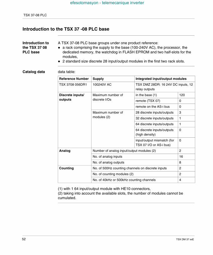
Introduction to the TSX 37 -08 PLC base
Introduction tothe TSX 37 08PLC base
A TSX 37-08 PLC base groups under one product reference: a rack comprising the supply to the base (100-240V AC), the processor, the
dedicated memory, the watchdog in FLASH EPROM and two half-slots for themodules,
2 standard size discrete 28 input/output modules in the first two rack slots.
Catalog data data table:
(1) with 1 64 input/output module with HE10 connectors,(2) taking into account the available slots, the number of modules cannot becumulated.
Reference Number Supply Integrated input/output modules
TSX 3708 056DR1 100240V AC TSX DMZ 28DR: 16 24V DC inputs, 12relay outputs
Discrete inputs/outputs
Maximum number ofdiscrete I/Os
in the base (1) 120
remote (TSX 07) 0
remote on the AS-i bus 0
Maximum number ofmodules (2)
28 discrete inputs/outputs 3
32 discrete inputs/outputs 1
64 discrete inputs/outputs 1
64 discrete inputs/outputs(high density)
0
input/output mismatch (forTSX 07 I/O or AS-i bus)
0
Analog Number of analog input/output modules (2) 2
No. of analog inputs 16
No. of analog outputs 8
Counting No. of 500Hz counting channels on discrete inputs 2
No. of counting modules (2) 2
No. of 40kHz or 500kHz counting channels 4
52 TSX DM 37 xxE
TSX 37-08 PLC
efesotomasyon - telemecanique inverter
RS 485 terminalport
With an 8-point mini-DIN size RS 485 terminal port, it is possible to: connect an FTX type terminal or a compatible PC, a printer, and to connect the PLC to the UNI-TELWAY or Modbus busses. For this, it
proposes, by default, the UNI-TELWAY 96 Baud master communication modeand, by configuration: the UNI-TELWAY slave mode or, ASCII character mode or, the Modbus protocol.
Note: The terminal and PLC can both be connected to the UNI-TELWAY bus usingthe TSX P ACC 01 insulating device. This should be used when the distancebetween the UNI-TELWAY connection equipment is greater than 10 meters (seeTSX unit P ACC 01, p. 345).
TSX DM 37 xxE 53
TSX 37-08 PLC
efesotomasyon - telemecanique inverter
TSX 37-08: physical description
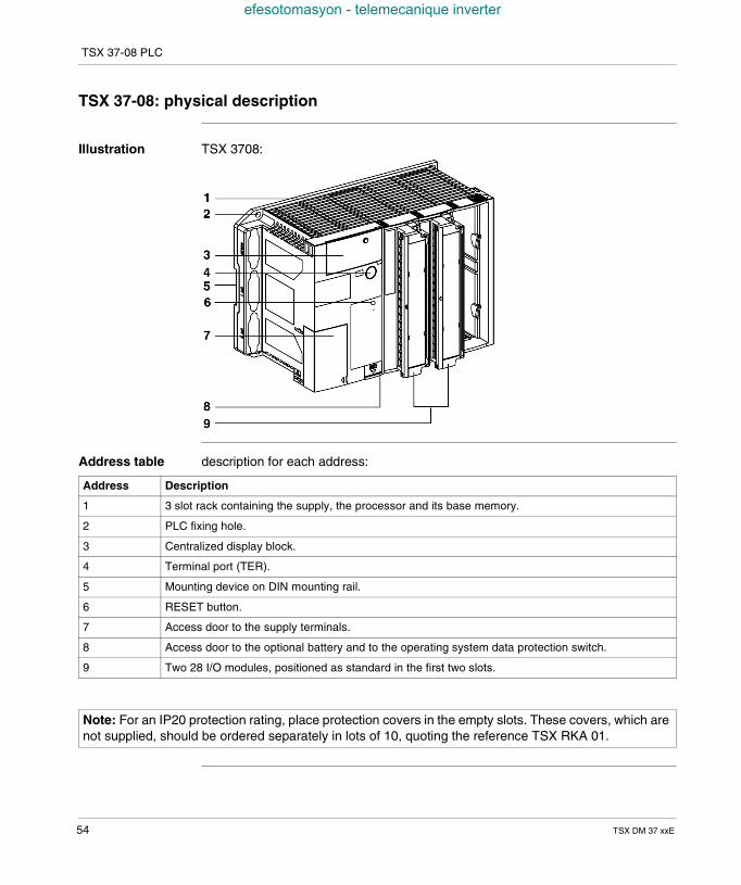
Illustration TSX 3708:
Address table description for each address:
Address Description
1 3 slot rack containing the supply, the processor and its base memory.
2 PLC fixing hole.
3 Centralized display block.
4 Terminal port (TER).
5 Mounting device on DIN mounting rail.
6 RESET button.
7 Access door to the supply terminals.
8 Access door to the optional battery and to the operating system data protection switch.
9 Two 28 I/O modules, positioned as standard in the first two slots.
Note: For an IP20 protection rating, place protection covers in the empty slots. These covers, which arenot supplied, should be ordered separately in lots of 10, quoting the reference TSX RKA 01.
54 TSX DM 37 xxE
TSX 37-08 PLC
efesotomasyon - telemecanique inverter
Characteristics of the TSX 37-08
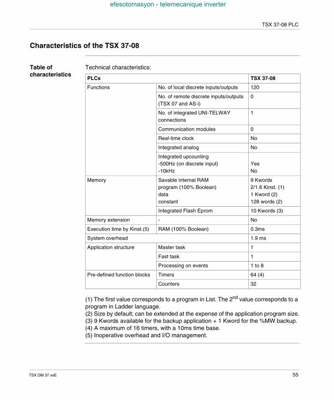
Table ofcharacteristics
Technical characteristics:
(1) The first value corresponds to a program in List. The 2nd value corresponds to aprogram in Ladder language.(2) Size by default; can be extended at the expense of the application program size.(3) 9 Kwords available for the backup application + 1 Kword for the %MW backup.(4) A maximum of 16 timers, with a 10ms time base.(5) Inoperative overhead and I/O management.
PLCs TSX 37-08
Functions No. of local discrete inputs/outputs 120
No. of remote discrete inputs/outputs(TSX 07 and AS-i)
0
No. of integrated UNI-TELWAYconnections
1
Communication modules 0
Real-time clock No
Integrated analog No
Integrated upcounting-500Hz (on discrete input)-10kHz
YesNo
Memory Savable internal RAMprogram (100% Boolean)dataconstant
9 Kwords2/1.6 Kinst. (1)1 Kword (2)128 words (2)
Integrated Flash Eprom 10 Kwords (3)
Memory extension - No
Execution time by Kinst.(5) RAM (100% Boolean) 0.3ms
System overhead 1.9 ms
Application structure Master task 1
Fast task 1
Processing on events 1 to 8
Pre-defined function blocks Timers 64 (4)
Counters 32
TSX DM 37 xxE 55
TSX 37-08 PLC
efesotomasyon - telemecanique inverter
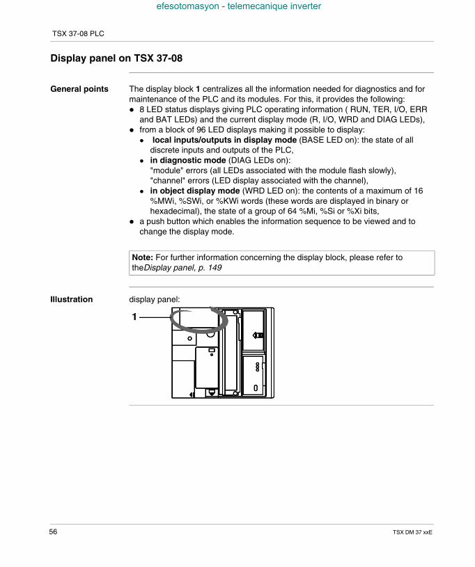
Display panel on TSX 37-08
General points The display block 1 centralizes all the information needed for diagnostics and formaintenance of the PLC and its modules. For this, it provides the following: 8 LED status displays giving PLC operating information ( RUN, TER, I/O, ERR
and BAT LEDs) and the current display mode (R, I/O, WRD and DIAG LEDs), from a block of 96 LED displays making it possible to display:
local inputs/outputs in display mode (BASE LED on): the state of alldiscrete inputs and outputs of the PLC,
in diagnostic mode (DIAG LEDs on):"module" errors (all LEDs associated with the module flash slowly),"channel" errors (LED display associated with the channel),
in object display mode (WRD LED on): the contents of a maximum of 16%MWi, %SWi, or %KWi words (these words are displayed in binary orhexadecimal), the state of a group of 64 %Mi, %Si or %Xi bits,
a push button which enables the information sequence to be viewed and tochange the display mode.
Illustration display panel:
Note: For further information concerning the display block, please refer totheDisplay panel, p. 149
56 TSX DM 37 xxE
TSX DM 37 xxE
efesotomasyon - telemecanique inverter
7
TSX 37-10PLCAt a Glance
Aim of thisChapter
This chapter is about the TSX 37-10 PLC, its physical description and its technicalcharacteristics.
What's in thisChapter?
This Chapter contains the following Maps:
Topic Page
Introduction to the TSX 37 -10 PLC base 58
TSX 37-10: description 60
Characteristics of the TSX 37-10 61
TSX 37-10 display block 62
57
TSX 37-10 PLC
efesotomasyon - telemecanique inverter
Introduction to the TSX 37 -10 PLC base
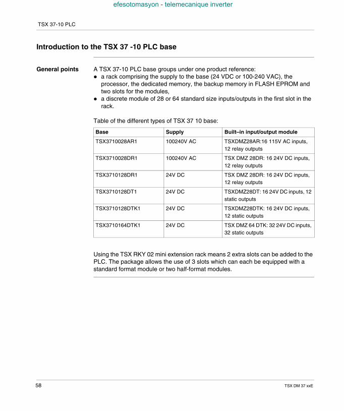
General points A TSX 37-10 PLC base groups under one product reference: a rack comprising the supply to the base (24 VDC or 100-240 VAC), the
processor, the dedicated memory, the backup memory in FLASH EPROM andtwo slots for the modules,
a discrete module of 28 or 64 standard size inputs/outputs in the first slot in therack.
Table of the different types of TSX 37 10 base:
Using the TSX RKY 02 mini extension rack means 2 extra slots can be added to thePLC. The package allows the use of 3 slots which can each be equipped with astandard format module or two half-format modules.
Base Supply Built–in input/output module
TSX3710028AR1 100240V AC TSXDMZ28AR:16 115V AC inputs,12 relay outputs
TSX3710028DR1 100240V AC TSX DMZ 28DR: 16 24V DC inputs,12 relay outputs
TSX3710128DR1 24V DC TSX DMZ 28DR: 16 24V DC inputs,12 relay outputs
TSX3710128DT1 24V DC TSXDMZ28DT: 16 24V DC inputs, 12static outputs
TSX3710128DTK1 24V DC TSXDMZ28DTK: 16 24V DC inputs,12 static outputs
TSX3710164DTK1 24V DC TSX DMZ 64 DTK: 32 24V DC inputs,32 static outputs
58 TSX DM 37 xxE
TSX 37-10 PLC
efesotomasyon - telemecanique inverter
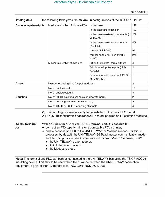
Catalog data the following table gives the maximum configurations of the TSX 37 10 PLCs:
(*) The counting modules are only to be installed in the basic PLC model.A TSX 37-10 configuration can receive 2 analog modules and 2 counting modules.
RS 485 terminalport
With an 8-point mini-DIN size RS 485 terminal port, it is possible to: connect an FTX type terminal or a compatible PC, a printer, and to connect the PLC to the UNI-TELWAY or Modbus busses. For this, it
proposes, by default, the UNI-TELWAY 96 Baud master communication modeand, by configuration (see Communication incorporated in the bases, p. 307: the UNI-TELWAY slave mode or, ASCII character mode or, the Modbus protocol.
Discrete inputs/outputs Maximum number of discrete I/Os in the base 128
in the base and extension 192
in the base + extension + remote (I/O TSX 07)
268
in the base + extension + remote(AS-i bus)
408
remote (4 TSX 07) 96
remote on the AS-i bus (124I +124O)
248
Maximum number of modules 28 or 32 discrete inputs/outputs 4
64 discrete inputs/outputs (highdensity)
2
input/output mismatch (for TSX 07 I/O or AS-i bus)
1
Analog Number of analog input/output modules 2
No. of analog inputs 16
No. of analog outputs 8
Counting No. of 500Hz counting channels on discrete inputs 2
No. of counting modules (in the PLC)(*) 2
No. of 40kHz or 500kHz counting channels 4
Note: The terminal and PLC can both be connected to the UNI-TELWAY bus using the TSX P ACC 01insulating device. This should be used when the distance between the UNI-TELWAY connectionequipment is greater than 10 meters (see TSX unit P ACC 01, p. 345).
TSX DM 37 xxE 59
TSX 37-10 PLC
efesotomasyon - telemecanique inverter
TSX 37-10: description
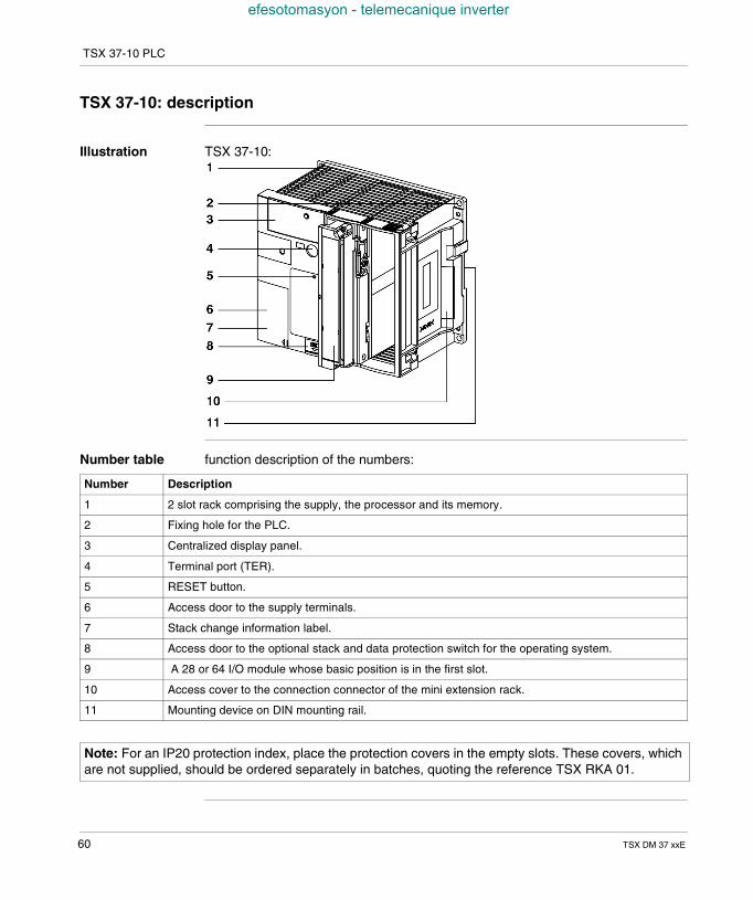
Illustration TSX 37-10:
Number table function description of the numbers:
Number Description
1 2 slot rack comprising the supply, the processor and its memory.
2 Fixing hole for the PLC.
3 Centralized display panel.
4 Terminal port (TER).
5 RESET button.
6 Access door to the supply terminals.
7 Stack change information label.
8 Access door to the optional stack and data protection switch for the operating system.
9 A 28 or 64 I/O module whose basic position is in the first slot.
10 Access cover to the connection connector of the mini extension rack.
11 Mounting device on DIN mounting rail.
Note: For an IP20 protection index, place the protection covers in the empty slots. These covers, whichare not supplied, should be ordered separately in batches, quoting the reference TSX RKA 01.
60 TSX DM 37 xxE
TSX 37-10 PLC
efesotomasyon - telemecanique inverter
Characteristics of the TSX 37-10
Table ofcharacteristics
Technical characteristics:
(1) The first value corresponds to a program in List. The 2nd value corresponds toa program in Ladder language.(2) Size by default; can be extended at the expense of the application program size.(3) 15 Kwords available for the backup application + 1 Kword for the %MW backup.(4) A maximum of 16 timers, with a 10ms time base.(5) Inoperative overhead and I/O management.
PLCs TSX 37-10
Functions No. of discrete input/outputTSX 07 local + remotelocal + remote on the AS-i bus
268408
No. of connectionsBuilt-in UNI-TELWAY
1
Communication modules 0
Real-time clock Yes
Integrated analog No
Integrated upcountingOn discrete inputs (-500 Hz)-10 kHz
YesNo
Internal memory Savable internal RAMprogram (100% Boolean) (1)data (in internal RAM)constant
14 Kwords4.7/2.7 Kinst.1 Kword (2)128 words (2)
Built-in Flash Eprom 16 Kwords (3)
Memory extension PCMCIA card No
Execution time byKinst.(5)
RAM (100% Boolean)PCMCIA (100% Boolean)
0.3ms-
System overhead 1.9 ms
Application structure Master task 1
Fast task 1
Task on events 1 to 8
Pre-defined functionblocks
Timers 64 (4)
Counters 32
TSX DM 37 xxE 61
TSX 37-10 PLC
efesotomasyon - telemecanique inverter
TSX 37-10 display block
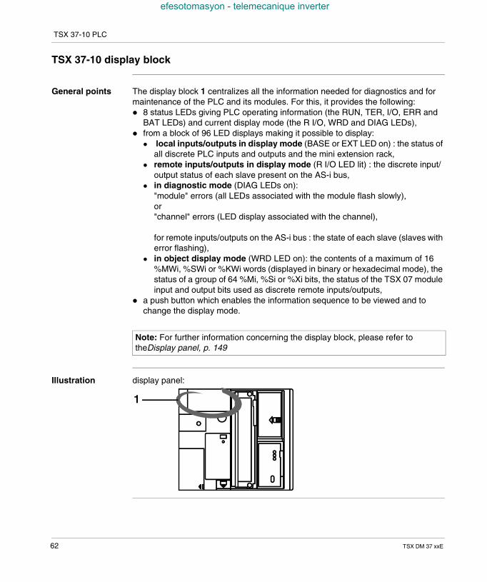
General points The display block 1 centralizes all the information needed for diagnostics and formaintenance of the PLC and its modules. For this, it provides the following: 8 status LEDs giving PLC operating information (the RUN, TER, I/O, ERR and
BAT LEDs) and current display mode (the R I/O, WRD and DIAG LEDs), from a block of 96 LED displays making it possible to display:
local inputs/outputs in display mode (BASE or EXT LED on) : the status ofall discrete PLC inputs and outputs and the mini extension rack,
remote inputs/outputs in display mode (R I/O LED lit) : the discrete input/output status of each slave present on the AS-i bus,
in diagnostic mode (DIAG LEDs on):"module" errors (all LEDs associated with the module flash slowly),or"channel" errors (LED display associated with the channel),
for remote inputs/outputs on the AS-i bus : the state of each slave (slaves witherror flashing),
in object display mode (WRD LED on): the contents of a maximum of 16%MWi, %SWi or %KWi words (displayed in binary or hexadecimal mode), thestatus of a group of 64 %Mi, %Si or %Xi bits, the status of the TSX 07 moduleinput and output bits used as discrete remote inputs/outputs,
a push button which enables the information sequence to be viewed and tochange the display mode.
Illustration display panel:
Note: For further information concerning the display block, please refer totheDisplay panel, p. 149
62 TSX DM 37 xxE
TSX DM 37 xxE
efesotomasyon - telemecanique inverter
8
TSX 37-21 and TSX 37-22 PLCsAt a Glance
Aim of thisChapter
This chapter is about the TSX 37-21 and TSX 37-22 PLCs, their physical descriptionand their technical characteristics.
What's in thisChapter?
This Chapter contains the following Maps:
Topic Page
Introduction to the TSX 37-21 and TSX 37-22 PLC bases 64
TSX 37-21 and TSX 37-22: description 66
Characteristics of the TSX 37-21 and the TSX 37-22 68
TSX 37-21 and TSX 37-22 display panel 70
63
TSX 37-21 and TSX 37-22 PLCs
efesotomasyon - telemecanique inverter
Introduction to the TSX 37-21 and TSX 37-22 PLC bases
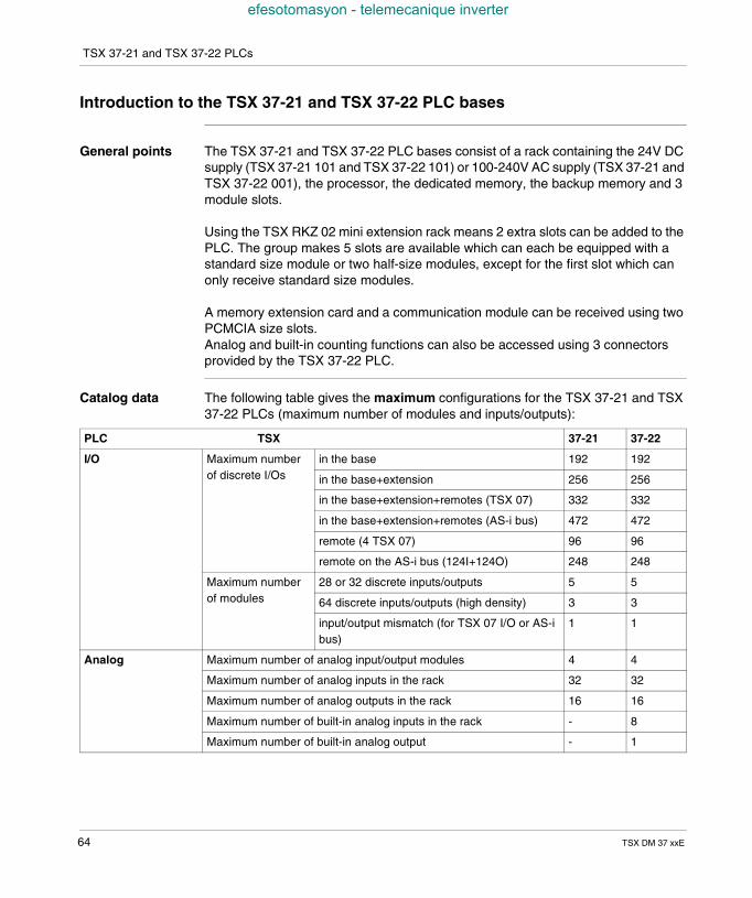
General points The TSX 37-21 and TSX 37-22 PLC bases consist of a rack containing the 24V DCsupply (TSX 37-21 101 and TSX 37-22 101) or 100-240V AC supply (TSX 37-21 andTSX 37-22 001), the processor, the dedicated memory, the backup memory and 3module slots.
Using the TSX RKZ 02 mini extension rack means 2 extra slots can be added to thePLC. The group makes 5 slots are available which can each be equipped with astandard size module or two half-size modules, except for the first slot which canonly receive standard size modules.
A memory extension card and a communication module can be received using twoPCMCIA size slots.Analog and built-in counting functions can also be accessed using 3 connectorsprovided by the TSX 37-22 PLC.
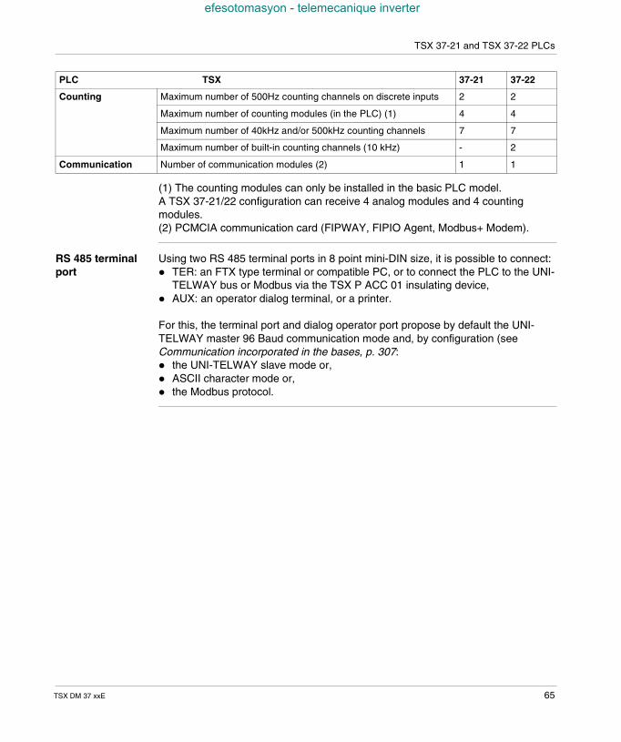
Catalog data The following table gives the maximum configurations for the TSX 37-21 and TSX37-22 PLCs (maximum number of modules and inputs/outputs):
PLC TSX 37-21 37-22
I/O Maximum numberof discrete I/Os
in the base 192 192
in the base+extension 256 256
in the base+extension+remotes (TSX 07) 332 332
in the base+extension+remotes (AS-i bus) 472 472
remote (4 TSX 07) 96 96
remote on the AS-i bus (124I+124O) 248 248
Maximum numberof modules
28 or 32 discrete inputs/outputs 5 5
64 discrete inputs/outputs (high density) 3 3
input/output mismatch (for TSX 07 I/O or AS-ibus)
1 1
Analog Maximum number of analog input/output modules 4 4
Maximum number of analog inputs in the rack 32 32
Maximum number of analog outputs in the rack 16 16
Maximum number of built-in analog inputs in the rack - 8
Maximum number of built-in analog output - 1
64 TSX DM 37 xxE
TSX 37-21 and TSX 37-22 PLCs
efesotomasyon - telemecanique inverter
(1) The counting modules can only be installed in the basic PLC model.A TSX 37-21/22 configuration can receive 4 analog modules and 4 countingmodules.(2) PCMCIA communication card (FIPWAY, FIPIO Agent, Modbus+ Modem).
RS 485 terminalport
Using two RS 485 terminal ports in 8 point mini-DIN size, it is possible to connect: TER: an FTX type terminal or compatible PC, or to connect the PLC to the UNI-
TELWAY bus or Modbus via the TSX P ACC 01 insulating device, AUX: an operator dialog terminal, or a printer.
For this, the terminal port and dialog operator port propose by default the UNI-TELWAY master 96 Baud communication mode and, by configuration (seeCommunication incorporated in the bases, p. 307: the UNI-TELWAY slave mode or, ASCII character mode or, the Modbus protocol.
Counting Maximum number of 500Hz counting channels on discrete inputs 2 2
Maximum number of counting modules (in the PLC) (1) 4 4
Maximum number of 40kHz and/or 500kHz counting channels 7 7
Maximum number of built-in counting channels (10 kHz) - 2
Communication Number of communication modules (2) 1 1
PLC TSX 37-21 37-22
TSX DM 37 xxE 65
TSX 37-21 and TSX 37-22 PLCs
efesotomasyon - telemecanique inverter
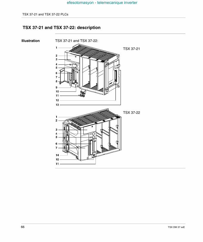
TSX 37-21 and TSX 37-22: description
Illustration TSX 37-21 and TSX 37-22:
TSX 37-21
TSX 37-22
66 TSX DM 37 xxE
TSX 37-21 and TSX 37-22 PLCs
efesotomasyon - telemecanique inverter
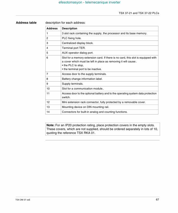
Address table description for each address:
Address Description
1 3 slot rack containing the supply, the processor and its base memory.
2 PLC fixing hole.
3 Centralized display block.
4 Terminal port TER.
5 AUX operator dialog port.
6 Slot for a memory extension card. If there is no card, this slot is equipped witha cover which must be left in place as removing it will cause:.• the PLC to stop,• the terminal port to be inactive.
7 Access door to the supply terminals.
8 Battery change information label.
9 Supply terminals.
10 Slot for a communication module..
11 Access door to the optional battery and to the operating system data protectionswitch.
12 Mini extension rack connector, fully protected by a removable cover.
13 Mounting device on DIN mounting rail.
14 Connectors for built-in analog and counting functions.
Note: For an IP20 protection rating, place protection covers in the empty slots.These covers, which are not supplied, should be ordered separately in lots of 10,quoting the reference TSX RKA 01.
TSX DM 37 xxE 67
TSX 37-21 and TSX 37-22 PLCs
efesotomasyon - telemecanique inverter
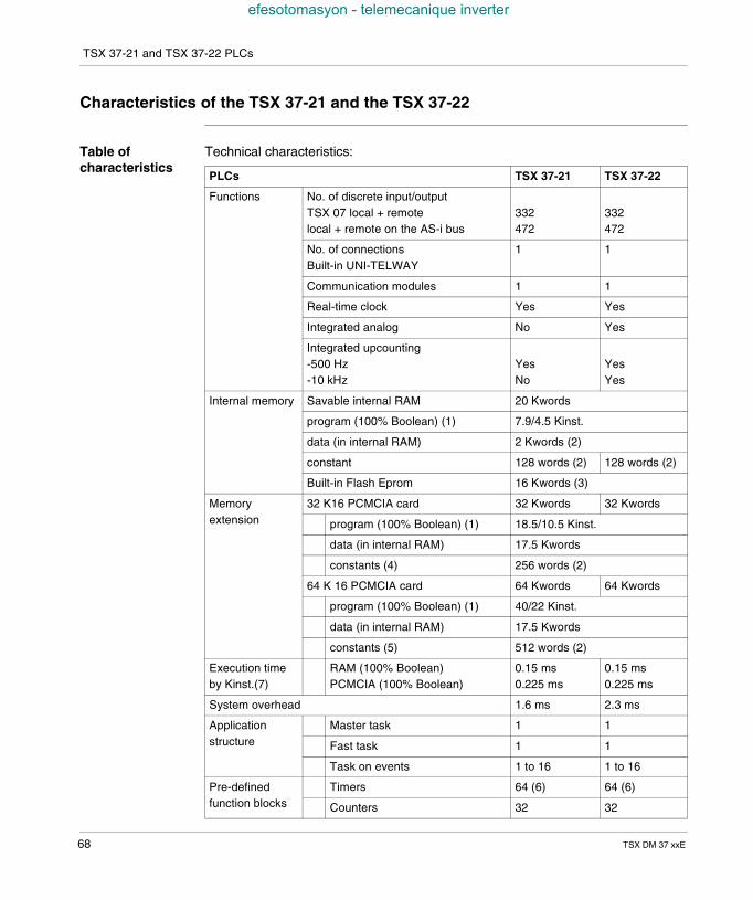
Characteristics of the TSX 37-21 and the TSX 37-22
Table ofcharacteristics
Technical characteristics:
PLCs TSX 37-21 TSX 37-22
Functions No. of discrete input/outputTSX 07 local + remotelocal + remote on the AS-i bus
332472
332472
No. of connectionsBuilt-in UNI-TELWAY
1 1
Communication modules 1 1
Real-time clock Yes Yes
Integrated analog No Yes
Integrated upcounting-500 Hz-10 kHz
YesNo
YesYes
Internal memory Savable internal RAM 20 Kwords
program (100% Boolean) (1) 7.9/4.5 Kinst.
data (in internal RAM) 2 Kwords (2)
constant 128 words (2) 128 words (2)
Built-in Flash Eprom 16 Kwords (3)
Memoryextension
32 K16 PCMCIA card 32 Kwords 32 Kwords
program (100% Boolean) (1) 18.5/10.5 Kinst.
data (in internal RAM) 17.5 Kwords
constants (4) 256 words (2)
64 K 16 PCMCIA card 64 Kwords 64 Kwords
program (100% Boolean) (1) 40/22 Kinst.
data (in internal RAM) 17.5 Kwords
constants (5) 512 words (2)
Execution timeby Kinst.(7)
RAM (100% Boolean)PCMCIA (100% Boolean)
0.15 ms0.225 ms
0.15 ms0.225 ms
System overhead 1.6 ms 2.3 ms
Applicationstructure
Master task 1 1
Fast task 1 1
Task on events 1 to 16 1 to 16
Pre-definedfunction blocks
Timers 64 (6) 64 (6)
Counters 32 32
68 TSX DM 37 xxE
TSX 37-21 and TSX 37-22 PLCs
efesotomasyon - telemecanique inverter
(1) The first value corresponds to a program in List. The 2nd value corresponds toa program in Ladder language.(2) Size by default; can be extended at the expense of the application program size.(3) 15 Kwords available for the backup application + 1 Kword for the %MW backup.(4) Can be extended to 24.5 Kwords.(5) Can be extended to 32 Kwords.(6) A maximum of 16 timers, with a 10ms time base.(7) Inoperative overhead and I/O management.
TSX DM 37 xxE 69
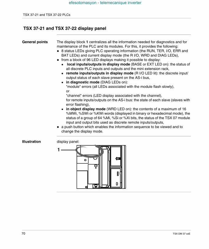
TSX 37-21 and TSX 37-22 PLCs
efesotomasyon - telemecanique inverter
TSX 37-21 and TSX 37-22 display panel
General points The display block 1 centralizes all the information needed for diagnostics and formaintenance of the PLC and its modules. For this, it provides the following: 8 status LEDs giving PLC operating information (the RUN, TER, I/O, ERR and
BAT LEDs) and current display mode (the R I/O, WRD and DIAG LEDs), from a block of 96 LED displays making it possible to display:
local inputs/outputs in display mode (BASE or EXT LED on): the status ofall discrete PLC inputs and outputs and the mini extension rack,
remote inputs/outputs in display mode (R I/O LED lit): the discrete input/output status of each slave present on the AS-i bus,
in diagnostic mode (DIAG LEDs on):"module" errors (all LEDs associated with the module flash slowly),or"channel" errors (LED display associated with the channel),for remote inputs/outputs on the AS-i bus: the state of each slave (slaves witherror flashing),
in object display mode (WRD LED on): the contents of a maximum of 16%MWi, %SWi or %KWi words (displayed in binary or hexadecimal mode), thestatus of a group of 64 %Mi, %Si or %Xi bits, the status of the TSX 07 moduleinput and output bits used as discrete remote inputs/outputs,
a push button which enables the information sequence to be viewed and tochange the display mode.
Illustration display panel:
70 TSX DM 37 xxE
TSX DM 37 xxE
efesotomasyon - telemecanique inverter
9
TSX 37 PLC suppliesAt a Glance
Aim of thisChapter
This chapter is about the TSX 37 PLC base supplies.
What's in thisChapter?
This Chapter contains the following Maps:
Topic Page
Alternating current supplies 72
Direct current supply 73
Additional characteristics 74
71
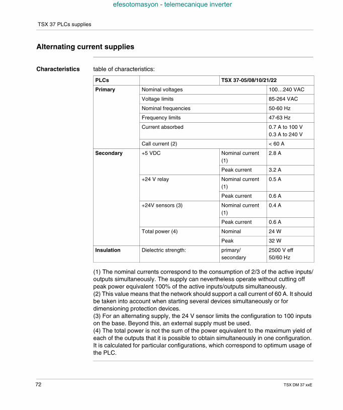
TSX 37 PLCs supplies
efesotomasyon - telemecanique inverter
Alternating current supplies
Characteristics table of characteristics:
(1) The nominal currents correspond to the consumption of 2/3 of the active inputs/outputs simultaneously. The supply can nevertheless operate without cutting offpeak power equivalent 100% of the active inputs/outputs simultaneously.(2) This value means that the network should support a call current of 60 A. It shouldbe taken into account when starting several devices simultaneously or fordimensioning protection devices.(3) For an alternating supply, the 24 V sensor limits the configuration to 100 inputson the base. Beyond this, an external supply must be used.(4) The total power is not the sum of the power equivalent to the maximum yield ofeach of the outputs that it is possible to obtain simultaneously in one configuration.It is calculated for particular configurations, which correspond to optimum usage ofthe PLC.
PLCs TSX 37-05/08/10/21/22
Primary Nominal voltages 100…240 VAC
Voltage limits 85-264 VAC
Nominal frequencies 50-60 Hz
Frequency limits 47-63 Hz
Current absorbed 0.7 A to 100 V0.3 A to 240 V
Call current (2) < 60 A
Secondary +5 VDC Nominal current(1)
2.8 A
Peak current 3.2 A
+24 V relay Nominal current(1)
0.5 A
Peak current 0.6 A
+24V sensors (3) Nominal current(1)
0.4 A
Peak current 0.6 A
Total power (4) Nominal 24 W
Peak 32 W
Insulation Dielectric strength: primary/secondary
2500 V eff50/60 Hz
72 TSX DM 37 xxE
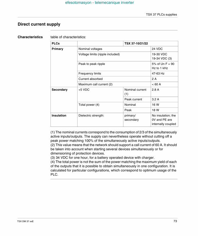
TSX 37 PLCs supplies
efesotomasyon - telemecanique inverter
Direct current supply
Characteristics table of characteristics:
(1) The nominal currents correspond to the consumption of 2/3 of the simultaneouslyactive inputs/outputs. The supply can nevertheless operate without cutting off apeak power matching 100% of the simultaneously active inputs/outputs.(2) This value means that the network should support a call current of 60 A. It shouldbe taken into account when starting several devices simultaneously or fordimensioning of protection devices.(3) 34 VDC for one hour, for a battery operated device with charger.(4) The total power is not the sum of the power matching the maximum yield of eachof the outputs that it is possible to obtain simultaneously in one configuration. It iscalculated for particular configurations, which correspond to optimum usage of thePLC.
PLCs TSX 37-10/21/22
Primary Nominal voltages 24 VDC
Voltage limits (ripple included) 19-30 VDC19-34 VDC (3)
Peak to peak ripple 5% of Un F = 90Hz to 1 kHz
Frequency limits 47-63 Hz
Current absorbed 2 A
Maximum call current (2) < 60 A
Secondary +5 VDC Nominal current(1)
2.8 A
Peak current 3.2 A
Total power (4) Nominal 16 W
Peak 18 W
Insulation Dielectric strength: primary/secondary
No insulation; the0V and PE areinternally coupled
TSX DM 37 xxE 73
TSX 37 PLCs supplies
efesotomasyon - telemecanique inverter
Additional characteristics
Supplyprotection
The supply provided by the TSX 37-05/08, TSX 37-10, TSX 37-21 and TSX 37-22PLCs are all protected against overloading and short circuits.A short circuit or overload on the 24 V sensor does not have any effect on the othervoltages. The 24 V sensor reappears when the error disappears.
Service signals During operation, a signal is generated when the PLC supply voltage exceeds thelimits (Power Fail).
Programmingterminal supply
The +5 VDC voltage, delivered by PLC to the terminal port, does not allow auto-supply of a programming terminal, but a pocket terminal with a very low powerconsumption (<200 mA).
74 TSX DM 37 xxE
TSX DM 37 xxE
efesotomasyon - telemecanique inverter
10
Memories on TSX 37At a Glance
Aim of thischapter
This chapter describes the memory on TSX 37.
What's in thisChapter?
This Chapter contains the following Maps:
Topic Page
Internal memory 76
PCMCIA memory extension cards on TSX 37-21/22 PLCs 77
Standard and Backup memory cards 79
Application + file type memory cards 80
75
Memories on TSX 37
efesotomasyon - telemecanique inverter
Internal memory
General points The internal memory store of the TSX 37-05/08/10/21/22 PLCs is composed of twoseparate stores : An internal RAM memory (1), which is used by the application program and which
has a capacity of : 9 Kwords for a TSX 37-05/08 PLC 14 Kwords for a TSX 37-10 PLC 20 Kwords for a TSX 37-21/22 PLC.
Furthermore, in the case of a TSX 37-21/22 PLC, the application memory can beextended with a 32 or 64 Kword PCMCIA memory card, of the RAM or FLASHEPROM type.
A FLASH EPROM memory of: 10 Kwords on the TSX 37-05/08 PLCs, 16 Kwords on the TSX 37-10/21/22 PLCs, which is a backup memory.
This memory is a backup memory:- of the application program (only 15 Kwords can be used as a backup for theapplication program on the TSX 37- 21/22 PLCs),- of the %MW internal words with a maximum of 1000 internal words (storereserved for 1 Kword).
(1) The internal RAM memory is backed up by an optional 3.6V battery with anautonomy of 2 years (see Inserting/changing the battery, p. 110).
Note: In some cases, (configuration error, application change), it may be useful tototally erase the contents of the internal RAM or FLASH EPROM of the PLC. Forthis, carry out the PLC power-up keeping the DIAG button pressed during therunning of the autotests (a minimum of 10 seconds).
76 TSX DM 37 xxE
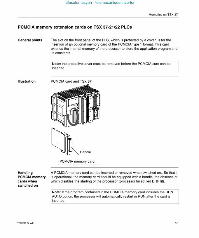
Memories on TSX 37
efesotomasyon - telemecanique inverter
PCMCIA memory extension cards on TSX 37-21/22 PLCs
General points The slot on the front panel of the PLC, which is protected by a cover, is for theinsertion of an optional memory card of the PCMCIA type 1 format. This cardextends the internal memory of the processor to store the application program andits constants.
Illustration PCMCIA card and TSX 37:
HandlingPCMCIA memorycards whenswitched on
A PCMCIA memory card can be inserted or removed when switched on.. So that itis operational, the memory card should be equipped with a handle, the absence ofwhich disables the starting of the processor (processor failed, led ERR lit).
Note: the protective cover must be removed before the PCMCIA card can beinserted.
Handle
PCMCIA memory card
Note: If the program contained in the PCMCIA memory card includes the RUNAUTO option, the processor will automatically restart in RUN after the card isinserted.
TSX DM 37 xxE 77
Memories on TSX 37
efesotomasyon - telemecanique inverter
Protection of theapplication
PMCIA cards are equipped with a lockout system which forbids write access(loading of a new program)This protection comes in addition to the software protection (see PL7 online help)which forbids read access to the program.
78 TSX DM 37 xxE
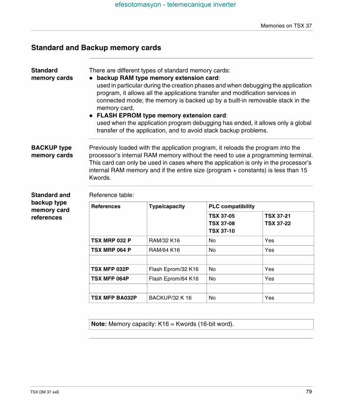
Memories on TSX 37
efesotomasyon - telemecanique inverter
Standard and Backup memory cards
Standardmemory cards
There are different types of standard memory cards: backup RAM type memory extension card:
used in particular during the creation phases and when debugging the applicationprogram, it allows all the applications transfer and modification services inconnected mode; the memory is backed up by a built-in removable stack in thememory card,
FLASH EPROM type memory extension card:used when the application program debugging has ended, it allows only a globaltransfer of the application, and to avoid stack backup problems.
BACKUP typememory cards
Previously loaded with the application program, it reloads the program into theprocessor’s internal RAM memory without the need to use a programming terminal.This card can only be used in cases where the application is only in the processor’sinternal RAM memory and if the entire size (program + constants) is less than 15Kwords.
Standard andbackup typememory cardreferences
Reference table:
References Type/capacity PLC compatibility
TSX 37-05TSX 37-08TSX 37-10
TSX 37-21TSX 37-22
TSX MRP 032 P RAM/32 K16 No Yes
TSX MRP 064 P RAM/64 K16 No Yes
TSX MFP 032P Flash Eprom/32 K16 No Yes
TSX MFP 064P Flash Eprom/64 K16 No Yes
TSX MFP BA032P BACKUP/32 K 16 No Yes
Note: Memory capacity: K16 = Kwords (16-bit word).
TSX DM 37 xxE 79
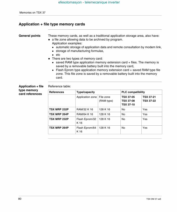
Memories on TSX 37
efesotomasyon - telemecanique inverter
Application + file type memory cards
General points These memory cards, as well as a traditional application storage area, also have: a file zone allowing data to be archived by program.
Application examples: automatic storage of application data and remote consultation by modem link, storage of manufacturing formulas, etc
There are two types of memory card: saved RAM type application memory extension card + files. The memory is
saved by a removable battery built into the memory card, Flash Eprom type application memory extension card + saved RAM type file
zone. This file zone is saved by a removable battery built into the memorycard.
Application + filetype memorycard references
Reference table:
References Type/capacity PLC compatibility
Application zone File zone(RAM type)
TSX 37-05TSX 37-08TSX 37-10
TSX 37-21TSX 37-22
TSX MRP 232P RAM/32 K 16 128 K 16 No Yes
TSX MRP 264P RAM/64 K 16 128 K 16 No Yes
TSX MRP 232P Flash Eprom/32K 16
128 K 16 No Yes
TSX MRP 264P Flash Eprom/64K 16
128 K 16 No Yes
80 TSX DM 37 xxE
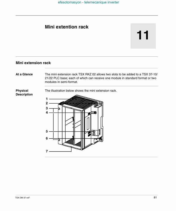
TSX DM 37 xxF
efesotomasyon - telemecanique inverter
11
Mini extention rackMini extension rack
At a Glance The mini extension rack TSX RKZ 02 allows two slots to be added to a TSX 37-10/21/22 PLC base; each of which can receive one module in standard format or twomodules in semi-format.
PhysicalDescription
The illustration below shows the mini extension rack.
81
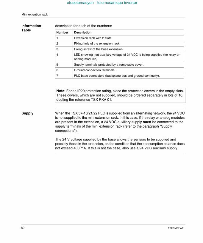
Mini extention rack
efesotomasyon - telemecanique inverter
InformationTable
description for each of the numbers:
Supply When the TSX 37-10/21/22 PLC is supplied from an alternating network, the 24 VDCis not supplied to the mini extension rack. In this case, if the relay or analog modulesare present in the extension, a 24 VDC auxiliary supply must be connected to thesupply terminals of the mini extension rack (refer to the paragraph "Supplyconnections").
The 24 V voltage supplied by the base allows the sensors to be supplied andpossibly those in the extension, on the condition that the consumption balance doesnot exceed 400 mA. If this is not the case, also use a 24 VDC auxiliary supply.
Number Description
1 Extension rack with 2 slots.
2 Fixing hole of the extension rack.
3 Fixing screw of the base extension.
4 LED showing that auxiliary voltage of 24 VDC is being supplied (for relay oranalog modules).
5 Supply terminals protected by a removable cover.
6 Ground connection terminals.
7 PLC base connectors (backplane bus and ground continuity).
Note: For an IP20 protection rating, place the protection covers in the empty slots.These covers, which are not supplied, should be ordered separately in lots of 10,quoting the reference TSX RKA 01.
82 TSXDM37xxF
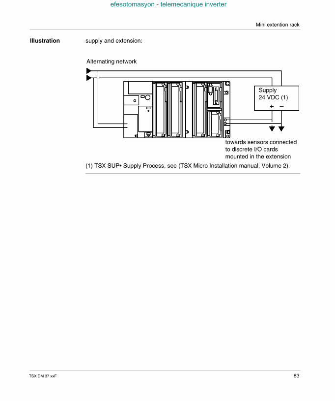
Mini extention rack
efesotomasyon - telemecanique inverter
Illustration supply and extension:
(1) TSX SUP• Supply Process, see (TSX Micro Installation manual, Volume 2).
Alternating network
Supply24 VDC (1)
towards sensors connectedto discrete I/O cardsmounted in the extension
TSX DM 37 xxF 83

Mini extention rack
efesotomasyon - telemecanique inverter
84 TSXDM37xxF
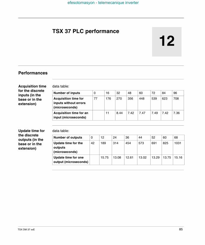
TSX DM 37 xxE
efesotomasyon - telemecanique inverter
12
TSX 37 PLC performancePerformances
Acquisition timefor the discreteinputs (in thebase or in theextension)
data table:
Update time forthe discreteoutputs (in thebase or in theextension)
data table:
Number of inputs 0 16 32 48 60 72 84 96
Acquisition time forinputs without errors(microseconds)
77 176 270 356 448 539 623 708
Acquisition time for aninput (microseconds)
11 8.44 7.42 7.47 7.49 7.42 7.36
Number of outputs 0 12 24 36 44 52 60 68
Update time for theoutputs(microseconds)
42 189 314 454 573 691 825 1031
Update time for oneoutput (microseconds)
15.75 13.08 12.61 13.02 13.29 13.75 15.16
85
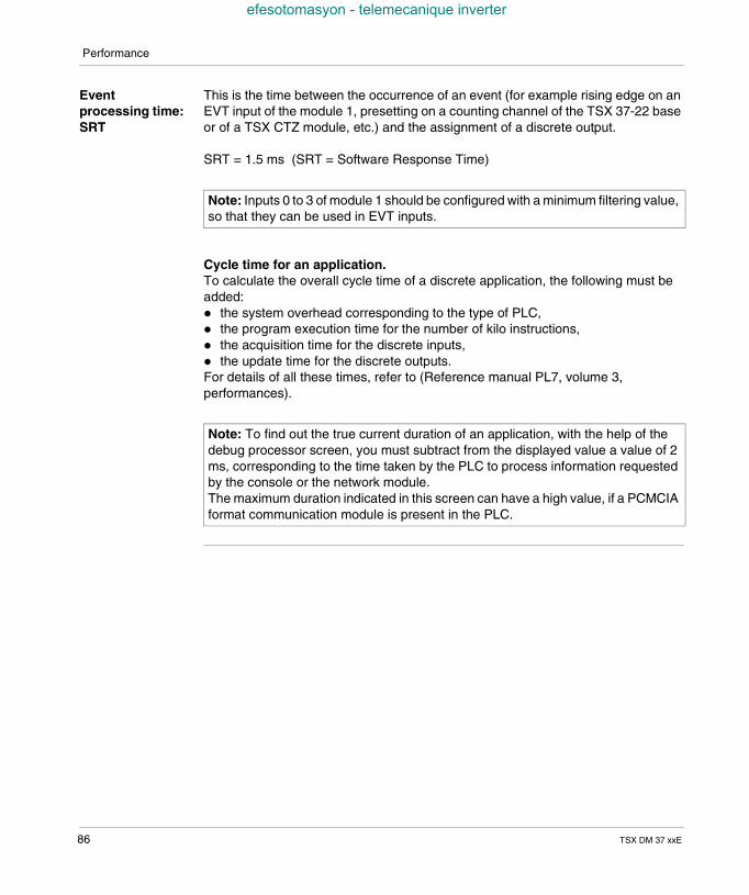
Performance
efesotomasyon - telemecanique inverter
Eventprocessing time:SRT
This is the time between the occurrence of an event (for example rising edge on anEVT input of the module 1, presetting on a counting channel of the TSX 37-22 baseor of a TSX CTZ module, etc.) and the assignment of a discrete output.
SRT = 1.5 ms (SRT = Software Response Time)
Cycle time for an application.To calculate the overall cycle time of a discrete application, the following must beadded: the system overhead corresponding to the type of PLC, the program execution time for the number of kilo instructions, the acquisition time for the discrete inputs, the update time for the discrete outputs.For details of all these times, refer to (Reference manual PL7, volume 3,performances).
Note: Inputs 0 to 3 of module 1 should be configured with a minimum filtering value,so that they can be used in EVT inputs.
Note: To find out the true current duration of an application, with the help of thedebug processor screen, you must subtract from the displayed value a value of 2ms, corresponding to the time taken by the PLC to process information requestedby the console or the network module.The maximum duration indicated in this screen can have a high value, if a PCMCIAformat communication module is present in the PLC.
86 TSX DM 37 xxE
TSX DM 37 xxE
efesotomasyon - telemecanique inverter
13
Commissioning standards andconditionsAt a Glance
Aim of thisChapter
This chapter is about the TSX Micro PLCs commissioning standards and conditions.
What's in thisChapter?
This Chapter contains the following Maps:
Topic Page
Standards and certifications 88
Operating conditions and environmental recommendations 89
Protection treatment for TSX 37 Micro PLCs 90
87
Commissioning standards and conditions
efesotomasyon - telemecanique inverter
Standards and certifications
General points The TSX 37 PLCs were designed to comply with the main national and internationalstandards for industrial process control electronic equipment: programmable PLCs: specific requirements: functional characteristics, immunity,
strength, safety, etc.IEC 61131-2, CSA 22.2 No.142, UL 508,
merchant navy requirements of the major international bodies:ABS, BV, DNV, GL, LROS, RINA, RRS, CCS, etc.
compliance with European Directives:Low Voltage: 73/23/EEC amendment 93/68/EECElectromagnetic Compatibility: 89/336/EEC amendments 92/31/EEC and 93/68/EEC,
electric qualities and self-extinguishability of insulating materials:UL 746C, UL 94, etc.
hazardous locations Cl1 Div2 CSA 22.2 No.213:"THIS EQUIPMENT IS SUITABLE FOR USE IN CLASS I, DIVISION 2,GROUPS A, B, C AND D ON NON-HAZARDOUS LOCATIONS ONLY".WARNING: "EXPLOSION HAZARD - DO NOT DISCONNECT WHILE CIRCUITIS LIVE UNLESS AREA IS KNOWN TO BE NON-HAZARDOUS"
88 TSX DM 37 xxE
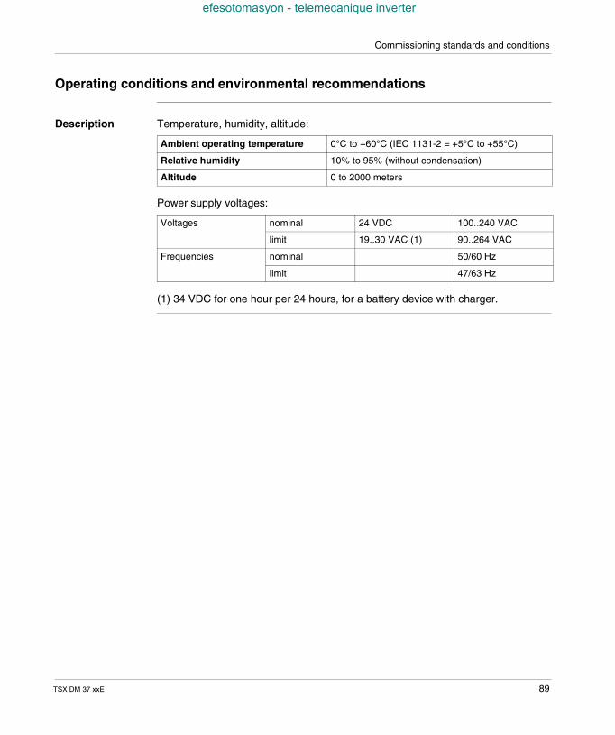
Commissioning standards and conditions
efesotomasyon - telemecanique inverter
Operating conditions and environmental recommendations
Description Temperature, humidity, altitude:
Power supply voltages:
(1) 34 VDC for one hour per 24 hours, for a battery device with charger.
Ambient operating temperature 0°C to +60°C (IEC 1131-2 = +5°C to +55°C)
Relative humidity 10% to 95% (without condensation)
Altitude 0 to 2000 meters
Voltages nominal 24 VDC 100..240 VAC
limit 19..30 VAC (1) 90..264 VAC
Frequencies nominal 50/60 Hz
limit 47/63 Hz
TSX DM 37 xxE 89
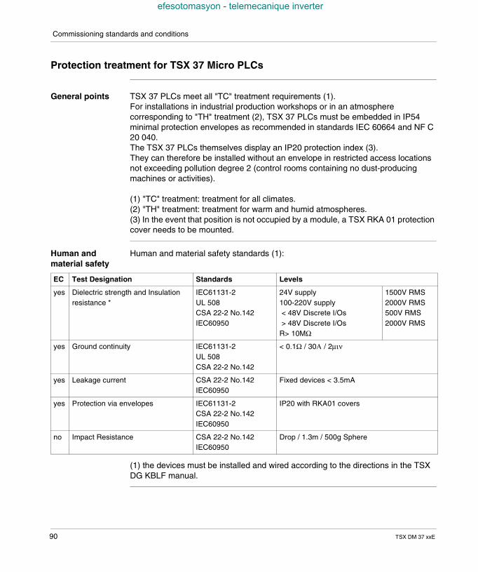
Commissioning standards and conditions
efesotomasyon - telemecanique inverter
Protection treatment for TSX 37 Micro PLCs
General points TSX 37 PLCs meet all "TC" treatment requirements (1).For installations in industrial production workshops or in an atmospherecorresponding to "TH" treatment (2), TSX 37 PLCs must be embedded in IP54minimal protection envelopes as recommended in standards IEC 60664 and NF C20 040.The TSX 37 PLCs themselves display an IP20 protection index (3).They can therefore be installed without an envelope in restricted access locationsnot exceeding pollution degree 2 (control rooms containing no dust-producingmachines or activities).
(1) "TC" treatment: treatment for all climates.(2) "TH" treatment: treatment for warm and humid atmospheres.(3) In the event that position is not occupied by a module, a TSX RKA 01 protectioncover needs to be mounted.
Human andmaterial safety
Human and material safety standards (1):
(1) the devices must be installed and wired according to the directions in the TSXDG KBLF manual.
EC Test Designation Standards Levels
yes Dielectric strength and Insulationresistance *
IEC61131-2UL 508CSA 22-2 No.142IEC60950
24V supply100-220V supply< 48V Discrete I/Os> 48V Discrete I/Os
R> 10MΩ
1500V RMS2000V RMS500V RMS2000V RMS
yes Ground continuity IEC61131-2UL 508CSA 22-2 No.142
< 0.1Ω / 30Α / 2µιν
yes Leakage current CSA 22-2 No.142IEC60950
Fixed devices < 3.5mA
yes Protection via envelopes IEC61131-2CSA 22-2 No.142IEC60950
IP20 with RKA01 covers
no Impact Resistance CSA 22-2 No.142IEC60950
Drop / 1.3m / 500g Sphere
90 TSX DM 37 xxE
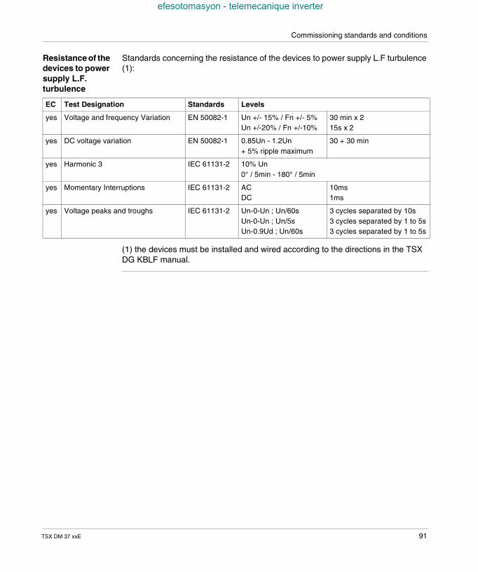
Commissioning standards and conditions
efesotomasyon - telemecanique inverter
Resistance of thedevices to powersupply L.F.turbulence
Standards concerning the resistance of the devices to power supply L.F turbulence(1):
(1) the devices must be installed and wired according to the directions in the TSXDG KBLF manual.
EC Test Designation Standards Levels
yes Voltage and frequency Variation EN 50082-1 Un +/- 15% / Fn +/- 5%Un +/-20% / Fn +/-10%
30 min x 215s x 2
yes DC voltage variation EN 50082-1 0.85Un - 1.2Un+ 5% ripple maximum
30 + 30 min
yes Harmonic 3 IEC 61131-2 10% Un0° / 5min - 180° / 5min
yes Momentary Interruptions IEC 61131-2 ACDC
10ms1ms
yes Voltage peaks and troughs IEC 61131-2 Un-0-Un ; Un/60sUn-0-Un ; Un/5sUn-0.9Ud ; Un/60s
3 cycles separated by 10s3 cycles separated by 1 to 5s3 cycles separated by 1 to 5s
TSX DM 37 xxE 91
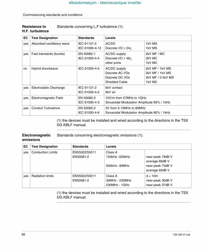
Commissioning standards and conditions
efesotomasyon - telemecanique inverter
Resistance toH.F. turbulence
Standards concerning L.F turbulence (1):
(1) the devices must be installed and wired according to the directions in the TSXDG KBLF manual.
Electromagneticemissions
Standards concerning electromagnetic emissions (1):
(1) the devices must be installed and wired according to the directions in the TSXDG KBLF manual.
EC Test Designation Standards Levels
yes Absorbed oscillatory wave IEC 61131-2IEC 61000-4-12
AC/DCDiscrete I/O ≥ 24ς
1kV MS1kV MS
yes Fast transients (bursts) EN 50082-1IEC 61000-4-4
AC/DC supplyDiscrete I/O > 48ςother ports
2kV MF / MC2kV MC1kV MC
no Hybrid shockwave IEC 61000-4-5 AC/DC supplyDiscrete AC I/OsDiscrete DC I/OsShielded Cable
2kV MF / 1kV MS2kV MF / 1kV MS2kV MF / 0.5kV MS1kV MC
yes Electrostatic Discharge IEC 61131-2IEC 61000-4-2
6kV contact8kV air
yes Electromagnetic Field EN 50082-2IEC 61000-4-3
10V/m from 27MHz to 1GHzSinusoidal Modulation Amplitude 80% / 1kHz
yes Conduit Turbulence EN 50082-2IEC 61000-4-6
3V from 0.15MHz to 80MHzSinusoidal Modulation Amplitude 80% / 1kHz
EC Test Designation Standards Levels
yes Conduction Limits EN55022/55011EN50081-2
Class A150kHz -500kHz
500kHz -30MHz
near-peak 79dB Vaverage 66dB Vnear-peak 73dB Vaverage 60dB V
yes Radiation limits EN55022/55011EN50081-2
Class A30MHz - 230MHz230MHz - 1GHz
d = 10mnear-peak 30dB Vnear-peak 37dB V
92 TSX DM 37 xxE
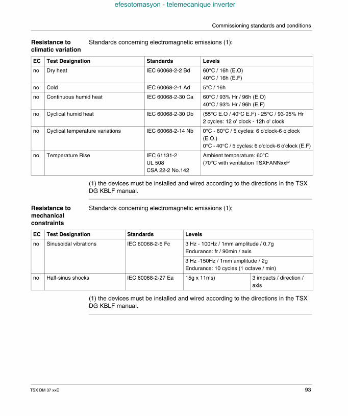
Commissioning standards and conditions
efesotomasyon - telemecanique inverter
Resistance toclimatic variation
Standards concerning electromagnetic emissions (1):
(1) the devices must be installed and wired according to the directions in the TSXDG KBLF manual.
Resistance tomechanicalconstraints
Standards concerning electromagnetic emissions (1):
(1) the devices must be installed and wired according to the directions in the TSXDG KBLF manual.
EC Test Designation Standards Levels
no Dry heat IEC 60068-2-2 Bd 60°C / 16h (E.O)40°C / 16h (E.F)
no Cold IEC 60068-2-1 Ad 5°C / 16h
no Continuous humid heat IEC 60068-2-30 Ca 60°C / 93% Hr / 96h (E.O)40°C / 93% Hr / 96h (E.F)
no Cyclical humid heat IEC 60068-2-30 Db (55°C E.O / 40°C E.F) - 25°C / 93-95% Hr2 cycles: 12 o' clock - 12h o' clock
no Cyclical temperature variations IEC 60068-2-14 Nb 0°C - 60°C / 5 cycles: 6 o'clock-6 o'clock(E.O.)0°C - 40°C / 5 cycles: 6 o'clock-6 o'clock (E.F)
no Temperature Rise IEC 61131-2UL 508CSA 22-2 No.142
Ambient temperature: 60°C(70°C with ventilation TSXFANNxxP
EC Test Designation Standards Levels
no Sinusoidal vibrations IEC 60068-2-6 Fc 3 Hz - 100Hz / 1mm amplitude / 0.7gEndurance: fr / 90min / axis
3 Hz -150Hz / 1mm amplitude / 2gEndurance: 10 cycles (1 octave / min)
no Half-sinus shocks IEC 60068-2-27 Ea 15g x 11ms) 3 impacts / direction /axis
TSX DM 37 xxE 93
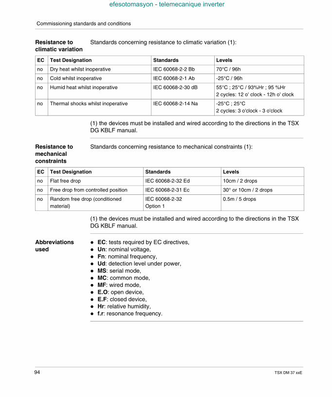
Commissioning standards and conditions
efesotomasyon - telemecanique inverter
Resistance toclimatic variation
Standards concerning resistance to climatic variation (1):
(1) the devices must be installed and wired according to the directions in the TSXDG KBLF manual.
Resistance tomechanicalconstraints
Standards concerning resistance to mechanical constraints (1):
(1) the devices must be installed and wired according to the directions in the TSXDG KBLF manual.
Abbreviationsused
EC: tests required by EC directives, Un: nominal voltage, Fn: nominal frequency, Ud: detection level under power, MS: serial mode, MC: common mode, MF: wired mode, E.O: open device, E.F: closed device, Hr: relative humidity, f.r: resonance frequency.
EC Test Designation Standards Levels
no Dry heat whilst inoperative IEC 60068-2-2 Bb 70°C / 96h
no Cold whilst inoperative IEC 60068-2-1 Ab -25°C / 96h
no Humid heat whilst inoperative IEC 60068-2-30 dB 55°C ; 25°C / 93%Hr ; 95 %Hr2 cycles: 12 o' clock - 12h o' clock
no Thermal shocks whilst inoperative IEC 60068-2-14 Na -25°C ; 25°C2 cycles: 3 o'clock - 3 o'clock
EC Test Designation Standards Levels
no Flat free drop IEC 60068-2-32 Ed 10cm / 2 drops
no Free drop from controlled position IEC 60068-2-31 Ec 30° or 10cm / 2 drops
no Random free drop (conditionedmaterial)
IEC 60068-2-32Option 1
0.5m / 5 drops
94 TSX DM 37 xxE
TSX DM 37 xxE
efesotomasyon - telemecanique inverter
III
TSX 37 PLC: MountingAt a Glance
Aim of this Part This part describes the installation and connection of the TSX 37 PLCs.
What's in thispart?
This Part contains the following Chapters:
Chapter Chaptername Page
14 TSX 37 PLC: installation 97
15 TSX 37 PLC: connection 117
16 Ventilation module 135
95

TSX 37 processor: Mounting
efesotomasyon - telemecanique inverter
96 TSX DM 37 xxE
TSX DM 37 xxE
efesotomasyon - telemecanique inverter
14
TSX 37 PLC: installationAt a Glance
Aim of thisChapter
This chapter describes the installation of the TSX 37 PLCs, their container and thedifferent modules.
What's in thisChapter?
This Chapter contains the following Maps:
Topic Page
Rules of installation 98
Dimensions 100
PLC mounting/fixing 101
Mounting the base onto a DIN profile (or rail) 102
Mounting the PLC onto a board or panel 103
Procedure for assembling the extension with the base 104
Inserting a module 106
Removing a module 108
Inserting/changing the battery 110
Mounting/removing the memory card 112
Changing the battery on the PCMCIA card 114
Screw tightening torque 116
97
Installation
efesotomasyon - telemecanique inverter
Rules of installation
PLCarrangement
Certain rules must be respected for installing containers and inserting modulesduring the mounting of the TSX 37 PLCs: The PLCs should be air-cooled by natural convection. To facilitate their
ventilation, they should be installed vertically with the ventilation louvers on thetop. Only the horizontal position is therefore authorized.
If several PLCs are installed in the same rack, it is recommended that thefollowing provisions be respected: leave a space of at least 150 mm between two overlapped PLCs, to allow a
passage for the wiring ducts and to facilitate air circulation, it is advised to install heat generating devices (transformers, supply modules,
power switches, etc) above the PLCs, leave a space of at least 100mm at each side of a PLC (with or without
extension) to allow a passage for the wiring and to facilitate air circulation, if the internal RAM memory is backed up by a battery (optional), it will be
necessary to provide sufficient space (>= 50 mm) between the PLC and theduct, in order to allow the hatch to be opened and access to the battery.
98 TSX DM 37 xxE
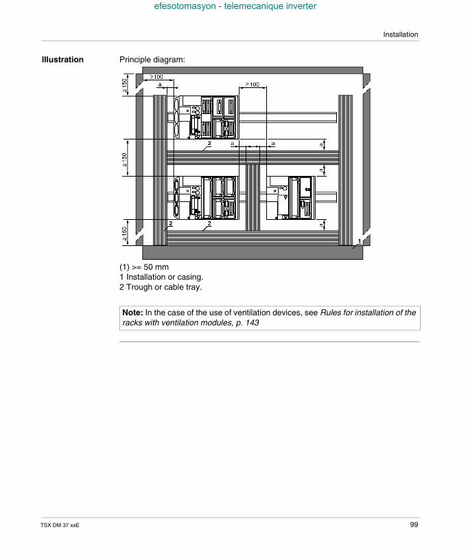
Installation
efesotomasyon - telemecanique inverter
Illustration Principle diagram:
(1) >= 50 mm1 Installation or casing.2 Trough or cable tray.
Note: In the case of the use of ventilation devices, see Rules for installation of theracks with ventilation modules, p. 143
TSX DM 37 xxE 99
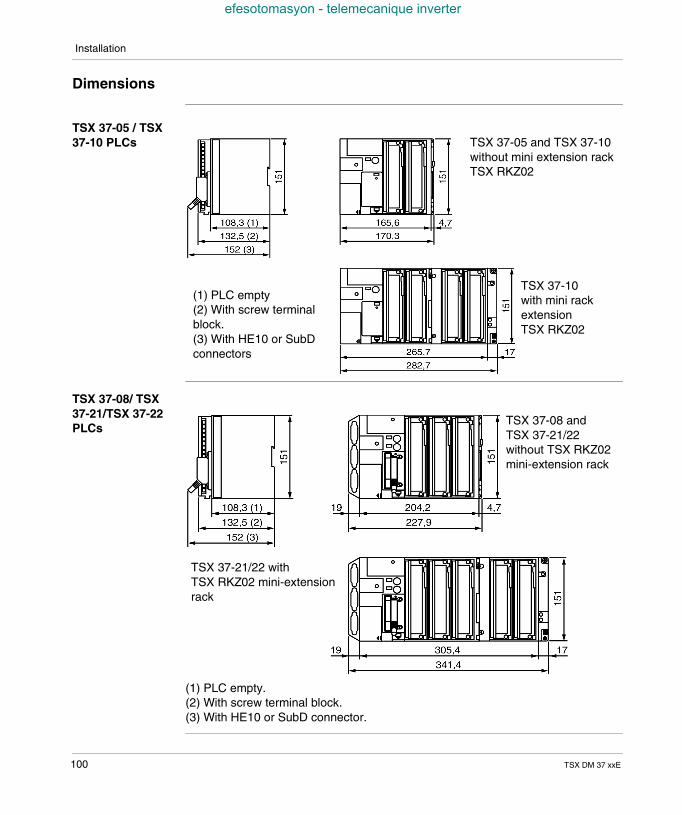
Installation
efesotomasyon - telemecanique inverter
Dimensions
TSX 37-05 / TSX37-10 PLCs
TSX 37-08/ TSX37-21/TSX 37-22PLCs
(1) PLC empty.(2) With screw terminal block.(3) With HE10 or SubD connector.
TSX 37-05 and TSX 37-10without mini extension rackTSX RKZ02
(1) PLC empty(2) With screw terminalblock.(3) With HE10 or SubDconnectors
TSX 37-10with mini rackextensionTSX RKZ02
TSX 37-08 andTSX 37-21/22without TSX RKZ02mini-extension rack
TSX 37-21/22 withTSX RKZ02 mini-extensionrack
100 TSX DM 37 xxE
Installation
efesotomasyon - telemecanique inverter
PLC mounting/fixing
General The TSX 37 PLCs, with or without mini extension rack can be mounted on a DINprofile, a Telequick board or on a panel: the process of fixing onto a DIN profile requires no accessories, the process of fixing onto a Telequick board or on a panel is performed by 4
screws with a diameter of M4 for the base and 2 screws with a diameter of M4 forthe mini extension rack, these 6 screws are not supplied. If mounting is difficult,from a mechanical point of view, it is preferable to fix the PLC onto a board orpanel.
The installation rules (See Rules of installation, p. 98) are to be respected, whateverthe type of mounting.
TSX DM 37 xxE 101
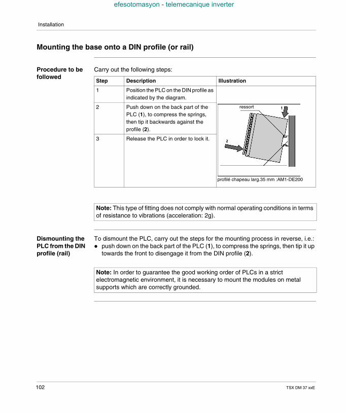
Installation
efesotomasyon - telemecanique inverter
Mounting the base onto a DIN profile (or rail)
Procedure to befollowed
Carry out the following steps:
Dismounting thePLC from the DINprofile (rail)
To dismount the PLC, carry out the steps for the mounting process in reverse, i.e.: push down on the back part of the PLC (1), to compress the springs, then tip it up
towards the front to disengage it from the DIN profile (2).
Step Description Illustration
1 Position the PLC on the DIN profile asindicated by the diagram.
2 Push down on the back part of thePLC (1), to compress the springs,then tip it backwards against theprofile (2).
3 Release the PLC in order to lock it.
Note: This type of fitting does not comply with normal operating conditions in termsof resistance to vibrations (acceleration: 2g).
ressort
profilé chapeau larg.35 mm :AM1-DE200
Note: In order to guarantee the good working order of PLCs in a strictelectromagnetic environment, it is necessary to mount the modules on metalsupports which are correctly grounded.
102 TSX DM 37 xxE
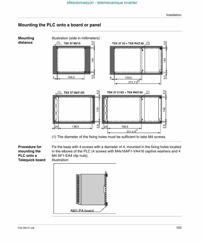
Installation
efesotomasyon - telemecanique inverter
Mounting the PLC onto a board or panel
Mountingdistance
Illustration (side in millimeters) :
(1) The diameter of the fixing holes must be sufficient to take M4 screws.
Procedure formounting thePLC onto aTelequick board
Fix the base with 4 screws with a diameter of 4, mounted in the fixing holes locatedin the elbows of the PLC (4 screws with M4x16AF1-VA416 captive washers and 4M4 AF1-EA4 clip nuts).Illustration:
AM1-PA board
TSX DM 37 xxE 103
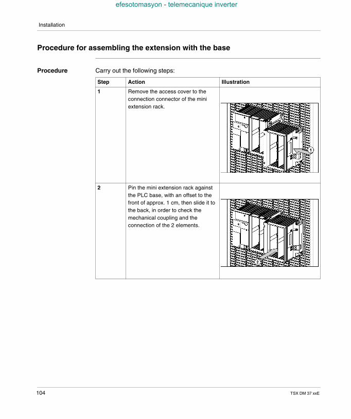
Installation
efesotomasyon - telemecanique inverter
Procedure for assembling the extension with the base
Procedure Carry out the following steps:
Step Action Illustration
1 Remove the access cover to theconnection connector of the miniextension rack.
2 Pin the mini extension rack againstthe PLC base, with an offset to thefront of approx. 1 cm, then slide it tothe back, in order to check themechanical coupling and theconnection of the 2 elements.
104 TSX DM 37 xxE
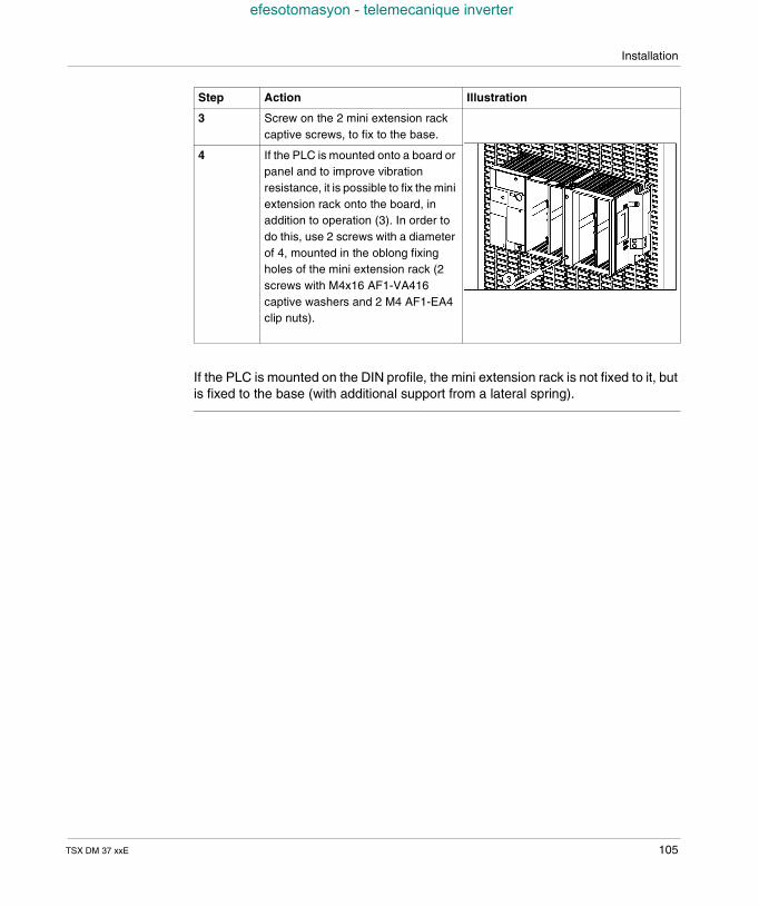
Installation
efesotomasyon - telemecanique inverter
If the PLC is mounted on the DIN profile, the mini extension rack is not fixed to it, butis fixed to the base (with additional support from a lateral spring).
3 Screw on the 2 mini extension rackcaptive screws, to fix to the base.
4 If the PLC is mounted onto a board orpanel and to improve vibrationresistance, it is possible to fix the miniextension rack onto the board, inaddition to operation (3). In order todo this, use 2 screws with a diameterof 4, mounted in the oblong fixingholes of the mini extension rack (2screws with M4x16 AF1-VA416captive washers and 2 M4 AF1-EA4clip nuts).
Step Action Illustration
TSX DM 37 xxE 105
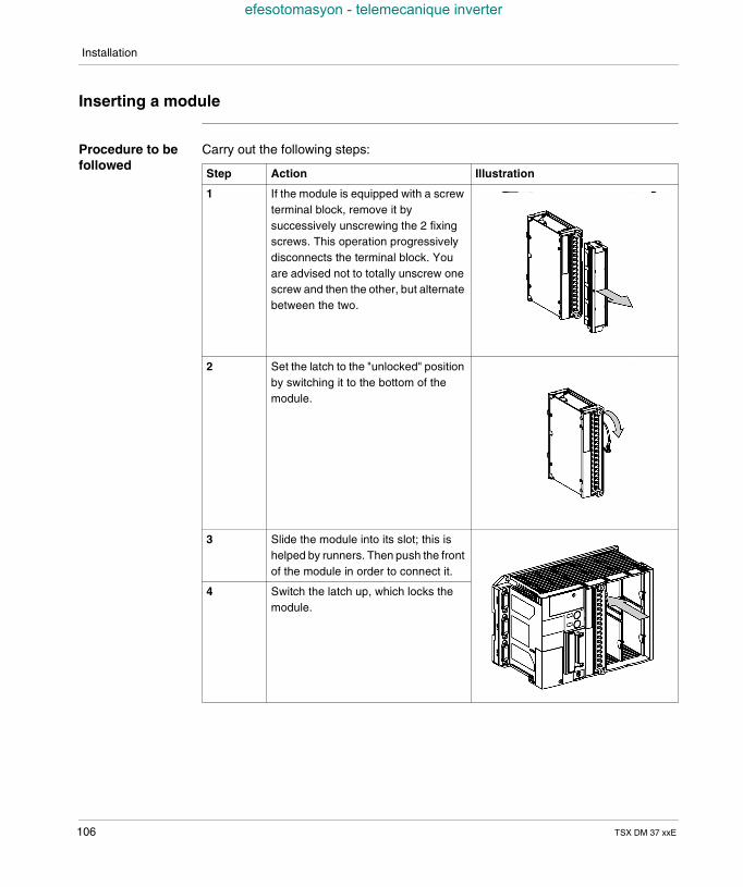
Installation
efesotomasyon - telemecanique inverter
Inserting a module
Procedure to befollowed
Carry out the following steps:
Step Action Illustration
1 If the module is equipped with a screwterminal block, remove it bysuccessively unscrewing the 2 fixingscrews. This operation progressivelydisconnects the terminal block. Youare advised not to totally unscrew onescrew and then the other, but alternatebetween the two.
2 Set the latch to the "unlocked" positionby switching it to the bottom of themodule.
3 Slide the module into its slot; this ishelped by runners. Then push the frontof the module in order to connect it.
4 Switch the latch up, which locks themodule.
106 TSX DM 37 xxE
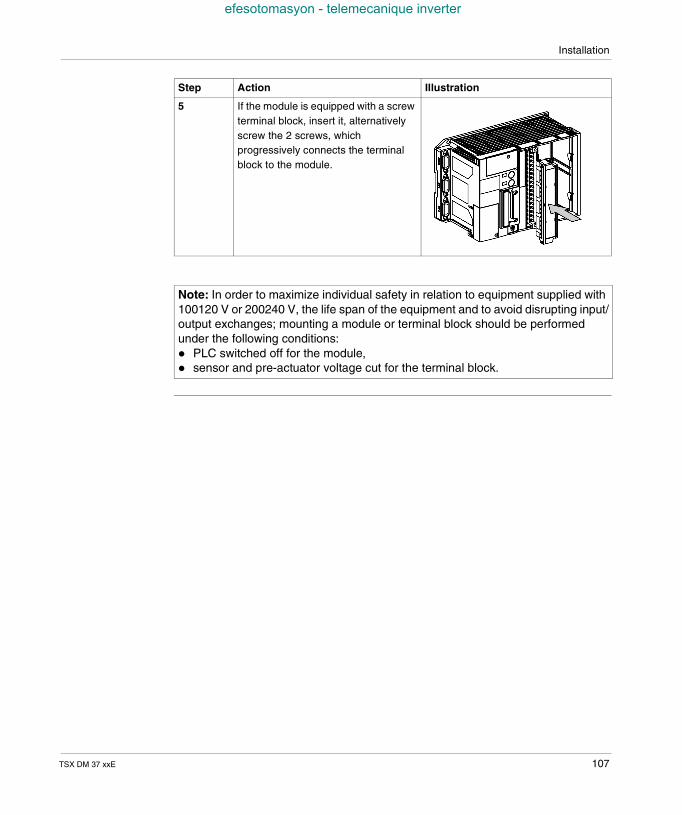
Installation
efesotomasyon - telemecanique inverter
5 If the module is equipped with a screwterminal block, insert it, alternativelyscrew the 2 screws, whichprogressively connects the terminalblock to the module.
Note: In order to maximize individual safety in relation to equipment supplied with100120 V or 200240 V, the life span of the equipment and to avoid disrupting input/output exchanges; mounting a module or terminal block should be performedunder the following conditions: PLC switched off for the module, sensor and pre-actuator voltage cut for the terminal block.
Step Action Illustration
TSX DM 37 xxE 107
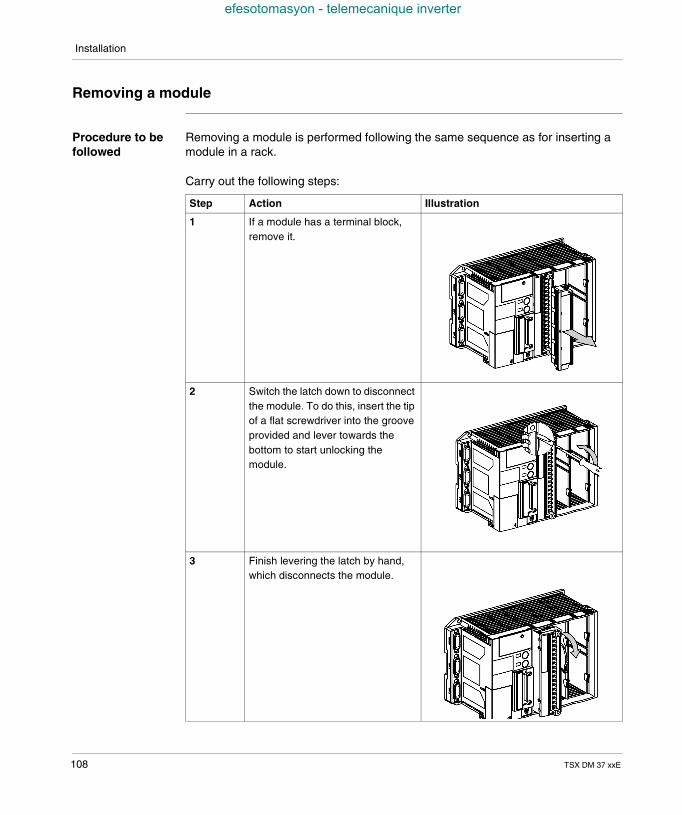
Installation
efesotomasyon - telemecanique inverter
Removing a module
Procedure to befollowed
Removing a module is performed following the same sequence as for inserting amodule in a rack.
Carry out the following steps:
Step Action Illustration
1 If a module has a terminal block,remove it.
2 Switch the latch down to disconnectthe module. To do this, insert the tipof a flat screwdriver into the grooveprovided and lever towards thebottom to start unlocking themodule.
3 Finish levering the latch by hand,which disconnects the module.
108 TSX DM 37 xxE
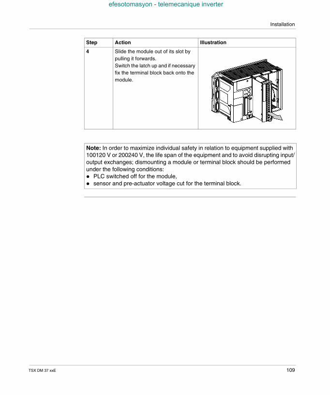
Installation
efesotomasyon - telemecanique inverter
4 Slide the module out of its slot bypulling it forwards.Switch the latch up and if necessaryfix the terminal block back onto themodule.
Note: In order to maximize individual safety in relation to equipment supplied with100120 V or 200240 V, the life span of the equipment and to avoid disrupting input/output exchanges; dismounting a module or terminal block should be performedunder the following conditions: PLC switched off for the module, sensor and pre-actuator voltage cut for the terminal block.
Step Action Illustration
TSX DM 37 xxE 109
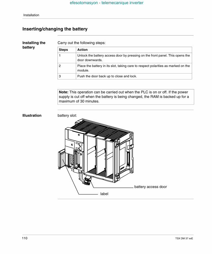
Installation
efesotomasyon - telemecanique inverter
Inserting/changing the battery
Installing thebattery
Carry out the following steps:
Illustration battery slot:
Steps Action
1 Unlock the battery access door by pressing on the front panel. This opens thedoor downwards.
2 Place the battery in its slot, taking care to respect polarities as marked on themodule.
3 Push the door back up to close and lock.
Note: This operation can be carried out when the PLC is on or off. If the powersupply is cut off when the battery is being changed, the RAM is backed up for amaximum of 30 minutes.
battery access door
label
110 TSX DM 37 xxE
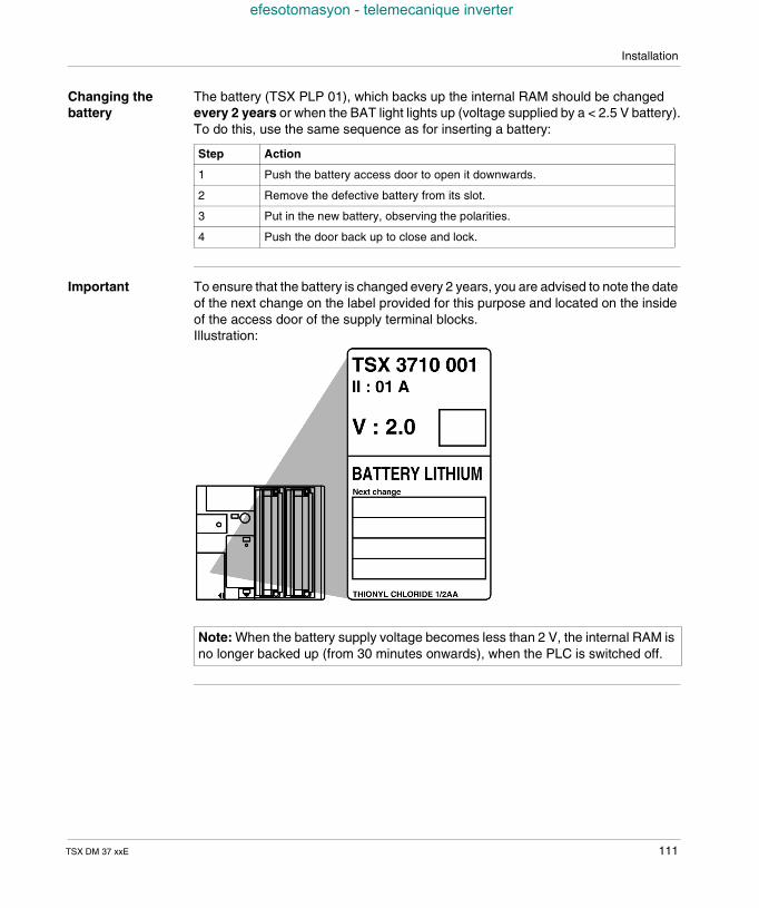
Installation
efesotomasyon - telemecanique inverter
Changing thebattery
The battery (TSX PLP 01), which backs up the internal RAM should be changedevery 2 years or when the BAT light lights up (voltage supplied by a < 2.5 V battery).To do this, use the same sequence as for inserting a battery:
Important To ensure that the battery is changed every 2 years, you are advised to note the dateof the next change on the label provided for this purpose and located on the insideof the access door of the supply terminal blocks.Illustration:
Step Action
1 Push the battery access door to open it downwards.
2 Remove the defective battery from its slot.
3 Put in the new battery, observing the polarities.
4 Push the door back up to close and lock.
Note: When the battery supply voltage becomes less than 2 V, the internal RAM isno longer backed up (from 30 minutes onwards), when the PLC is switched off.
TSX DM 37 xxE 111
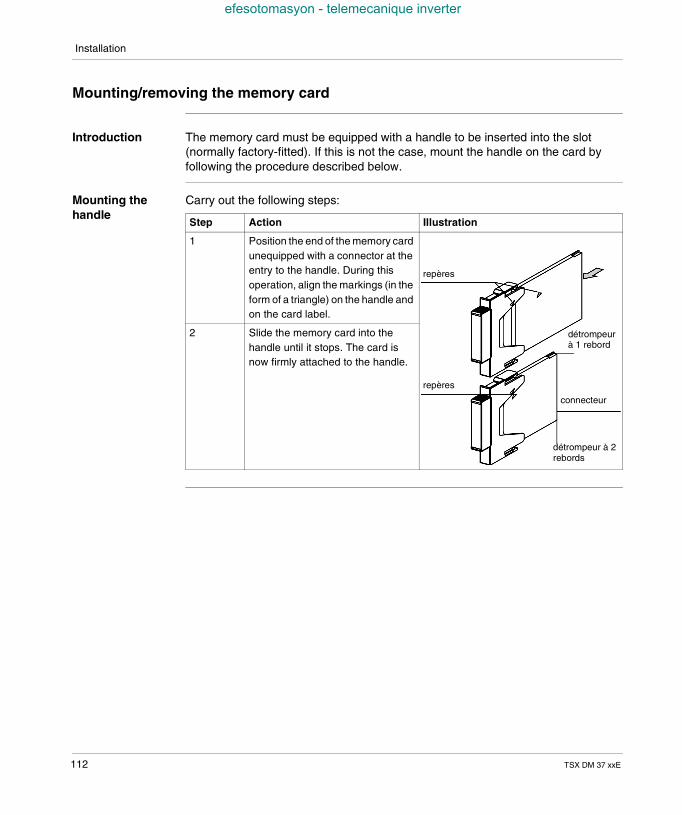
Installation
efesotomasyon - telemecanique inverter
Mounting/removing the memory card
Introduction The memory card must be equipped with a handle to be inserted into the slot(normally factory-fitted). If this is not the case, mount the handle on the card byfollowing the procedure described below.
Mounting thehandle
Carry out the following steps:
Step Action Illustration
1 Position the end of the memory cardunequipped with a connector at theentry to the handle. During thisoperation, align the markings (in theform of a triangle) on the handle andon the card label.
2 Slide the memory card into thehandle until it stops. The card isnow firmly attached to the handle.
repères
détrompeurà 1 rebord
connecteur
repères
détrompeur à 2rebords
112 TSX DM 37 xxE
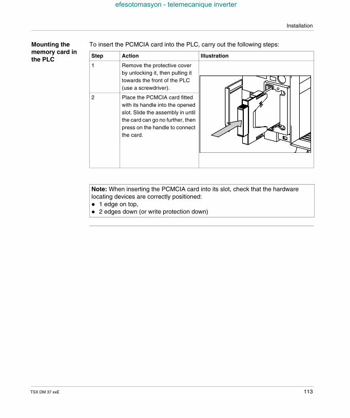
Installation
efesotomasyon - telemecanique inverter
Mounting thememory card inthe PLC
To insert the PCMCIA card into the PLC, carry out the following steps:
Step Action Illustration
1 Remove the protective coverby unlocking it, then pulling ittowards the front of the PLC(use a screwdriver).
2 Place the PCMCIA card fittedwith its handle into the openedslot. Slide the assembly in untilthe card can go no further, thenpress on the handle to connectthe card.
Note: When inserting the PCMCIA card into its slot, check that the hardwarelocating devices are correctly positioned: 1 edge on top, 2 edges down (or write protection down)
TSX DM 37 xxE 113
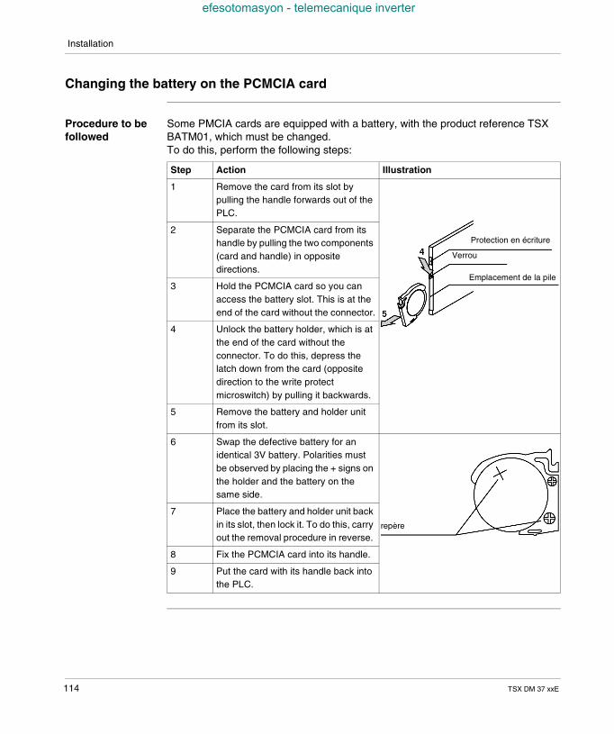
Installation
efesotomasyon - telemecanique inverter
Changing the battery on the PCMCIA card
Procedure to befollowed
Some PMCIA cards are equipped with a battery, with the product reference TSXBATM01, which must be changed.To do this, perform the following steps:
Step Action Illustration
1 Remove the card from its slot bypulling the handle forwards out of thePLC.
2 Separate the PCMCIA card from itshandle by pulling the two components(card and handle) in oppositedirections.
3 Hold the PCMCIA card so you canaccess the battery slot. This is at theend of the card without the connector.
4 Unlock the battery holder, which is atthe end of the card without theconnector. To do this, depress thelatch down from the card (oppositedirection to the write protectmicroswitch) by pulling it backwards.
5 Remove the battery and holder unitfrom its slot.
6 Swap the defective battery for anidentical 3V battery. Polarities mustbe observed by placing the + signs onthe holder and the battery on thesame side.
7 Place the battery and holder unit backin its slot, then lock it. To do this, carryout the removal procedure in reverse.
8 Fix the PCMCIA card into its handle.
9 Put the card with its handle back intothe PLC.
Protection en écriture
Verrou
Emplacement de la pile
repère
114 TSX DM 37 xxE
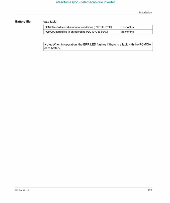
Installation
efesotomasyon - telemecanique inverter
Battery life data table:
PCMCIA card stored in normal conditions (-20°C to 70°C) 12 months
PCMCIA card fitted in an operating PLC (0°C to 60°C) 36 months
Note: When in operation, the ERR LED flashes if there is a fault with the PCMCIAcard battery.
TSX DM 37 xxE 115
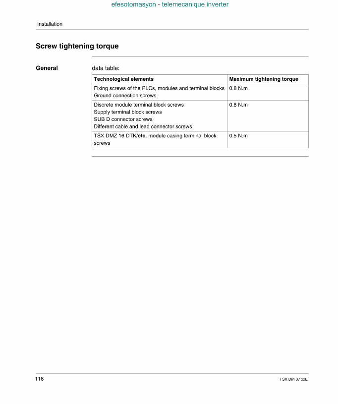
Installation
efesotomasyon - telemecanique inverter
Screw tightening torque
General data table:
Technological elements Maximum tightening torque
Fixing screws of the PLCs, modules and terminal blocksGround connection screws
0.8 N.m
Discrete module terminal block screwsSupply terminal block screwsSUB D connector screwsDifferent cable and lead connector screws
0.8 N.m
TSX DMZ 16 DTK/etc. module casing terminal blockscrews
0.5 N.m
116 TSX DM 37 xxE
TSX DM 37 xxE
efesotomasyon - telemecanique inverter
15
TSX 37 PLC: connectionAt a Glance
Aim of thisChapter
This Chapter deals with the connection of TSX 37 PLCs.
What's in thisChapter?
This Chapter contains the following Maps:
Topic Page
Ground connection of the PLC 118
Grounding the modules 119
Supply connections 120
Connection rules 121
Connecting PLCs supplied with alternating current 122
Connecting several PLCs supplied by TBX SUP 10 or TSX SUP supplies.... 125
Connecting PLCs supplied with direct current 126
Connecting PLC(s) supplied by a continuous floating network (not grounded) 129
Specific provisions for a continuous floating network 131
Sensor and pre actuator supply control 132
117
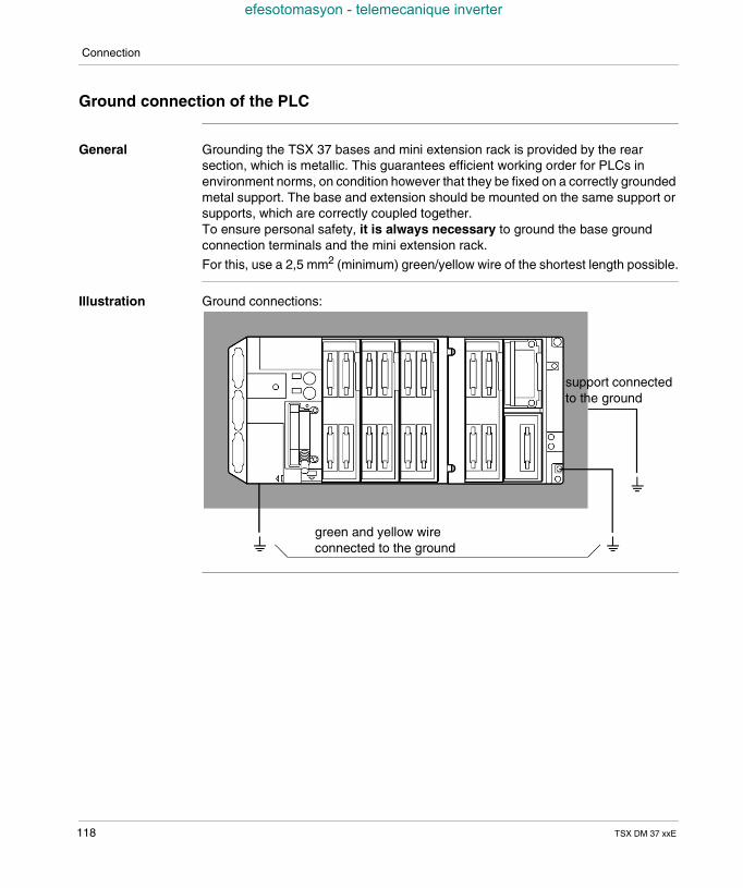
Connection
efesotomasyon - telemecanique inverter
Ground connection of the PLC
General Grounding the TSX 37 bases and mini extension rack is provided by the rearsection, which is metallic. This guarantees efficient working order for PLCs inenvironment norms, on condition however that they be fixed on a correctly groundedmetal support. The base and extension should be mounted on the same support orsupports, which are correctly coupled together.To ensure personal safety, it is always necessary to ground the base groundconnection terminals and the mini extension rack.
For this, use a 2,5 mm2 (minimum) green/yellow wire of the shortest length possible.
Illustration Ground connections:
green and yellow wireconnected to the ground
support connectedto the ground
118 TSX DM 37 xxE
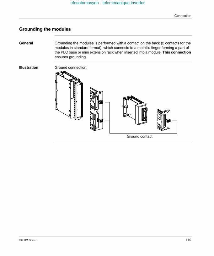
Connection
efesotomasyon - telemecanique inverter
Grounding the modules
General Grounding the modules is performed with a contact on the back (2 contacts for themodules in standard format), which connects to a metallic finger forming a part ofthe PLC base or mini extension rack when inserted into a module. This connectionensures grounding.
Illustration Ground connection:
Ground contact
TSX DM 37 xxE 119
Connection
efesotomasyon - telemecanique inverter
Supply connections
Introduction The TSX 37 range offers two possibilities for the supply of PLCs: alternating current, and direct current.
The PLC issupplied withalternatingcurrent
the base delivers the 24 VDC (24 VR) voltage necessary to supply the coils of itsintegrated relay modules,
however, the mini extension rack must be supplied with 24 VDC in the followingcases: analog modules are positioned in the extension, relay modules are positioned in the extension, The 24 VDC supply tolerance
must be +/- 10% max. If this voltage disappears or there is a reduction of morethan 10%, good working order of the relay modules is no longer ensured. Noerror indication is given to the application program. If detection of this error isdesired, you are advised, for example, to use a dividing bridge inline with ananalog input of the base configuration.
The PLC issupplied withdirect current (24VDC notinsulated)
The base delivers the 24 VDC (24 VR) voltage necessary to supply the coils ofthe relay/analog modules that are integrated in the base and/or the miniextension rack.The TSX 37 PLCs and modules can continuously function in a voltage rangebetween 19 and 30 VDC (and up to 34 VDC for 1 hour for a battery operateddevice with charger).However, if relay modules are fitted to the PLC (base or extension), the 24 VDCsupply should have a maximum tolerance of +/- 10%.
A TSX SUP supply can be used to provide the 24 VDC voltage (refer to wiringdiagrams on the following pages).
Note: When the PLC is supplied with alternating current, it is strictly forbidden touse the 24 V sensor voltage, provided by the base, to supply the mini extensionrack with 24 VDC (24 VR).
120 TSX DM 37 xxE
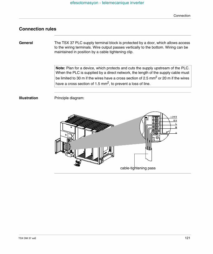
Connection
efesotomasyon - telemecanique inverter
Connection rules
General The TSX 37 PLC supply terminal block is protected by a door, which allows accessto the wiring terminals. Wire output passes vertically to the bottom. Wiring can bemaintained in position by a cable tightening clip.
Illustration Principle diagram:
Note: Plan for a device, which protects and cuts the supply upstream of the PLC.When the PLC is supplied by a direct network, the length of the supply cable must
be limited to 30 m if the wires have a cross section of 2.5 mm2 or 20 m if the wires
have a cross section of 1.5 mm2, to prevent a loss of line.
cable-tightening pass
TSX DM 37 xxE 121
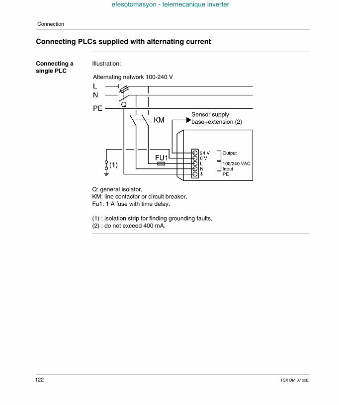
Connection
efesotomasyon - telemecanique inverter
Connecting PLCs supplied with alternating current
Connecting asingle PLC
Illustration:
Q: general isolator,KM: line contactor or circuit breaker,Fu1: 1 A fuse with time delay.
(1) : isolation strip for finding grounding faults,(2) : do not exceed 400 mA.
Alternating network 100-240 V
Sensor supplybase+extension (2)
122 TSX DM 37 xxE
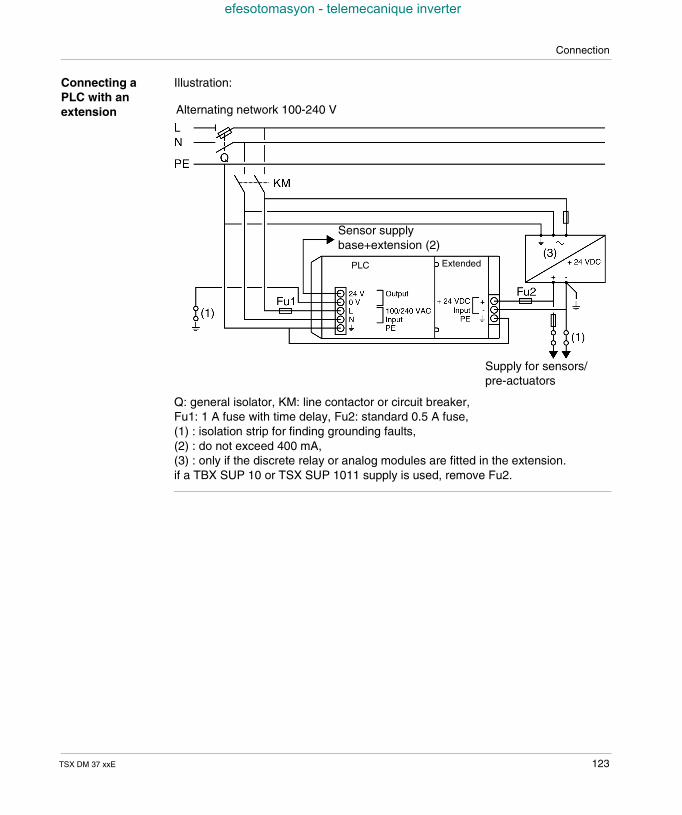
Connection
efesotomasyon - telemecanique inverter
Connecting aPLC with anextension
Illustration:
Q: general isolator, KM: line contactor or circuit breaker,Fu1: 1 A fuse with time delay, Fu2: standard 0.5 A fuse,(1) : isolation strip for finding grounding faults,(2) : do not exceed 400 mA,(3) : only if the discrete relay or analog modules are fitted in the extension.if a TBX SUP 10 or TSX SUP 1011 supply is used, remove Fu2.
Alternating network 100-240 V
Sensor supplybase+extension (2)
Supply for sensors/pre-actuators
PLC Extended
TSX DM 37 xxE 123
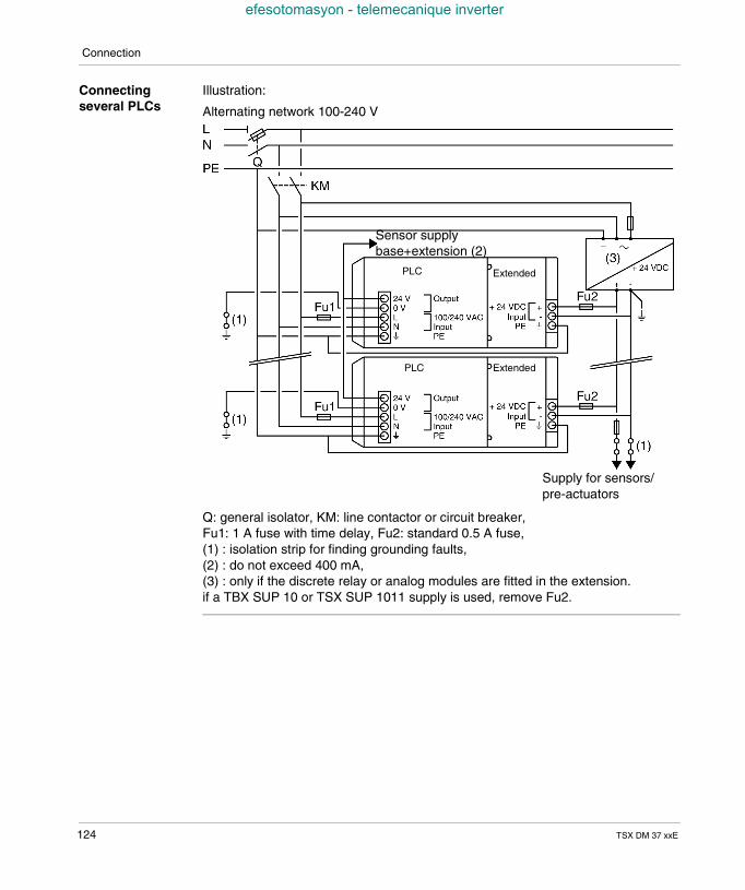
Connection
efesotomasyon - telemecanique inverter
Connectingseveral PLCs
Illustration:
Q: general isolator, KM: line contactor or circuit breaker,Fu1: 1 A fuse with time delay, Fu2: standard 0.5 A fuse,(1) : isolation strip for finding grounding faults,(2) : do not exceed 400 mA,(3) : only if the discrete relay or analog modules are fitted in the extension.if a TBX SUP 10 or TSX SUP 1011 supply is used, remove Fu2.
Alternating network 100-240 V
Sensor supplybase+extension (2)
PLC
PLC
Extended
Extended
Supply for sensors/pre-actuators
124 TSX DM 37 xxE
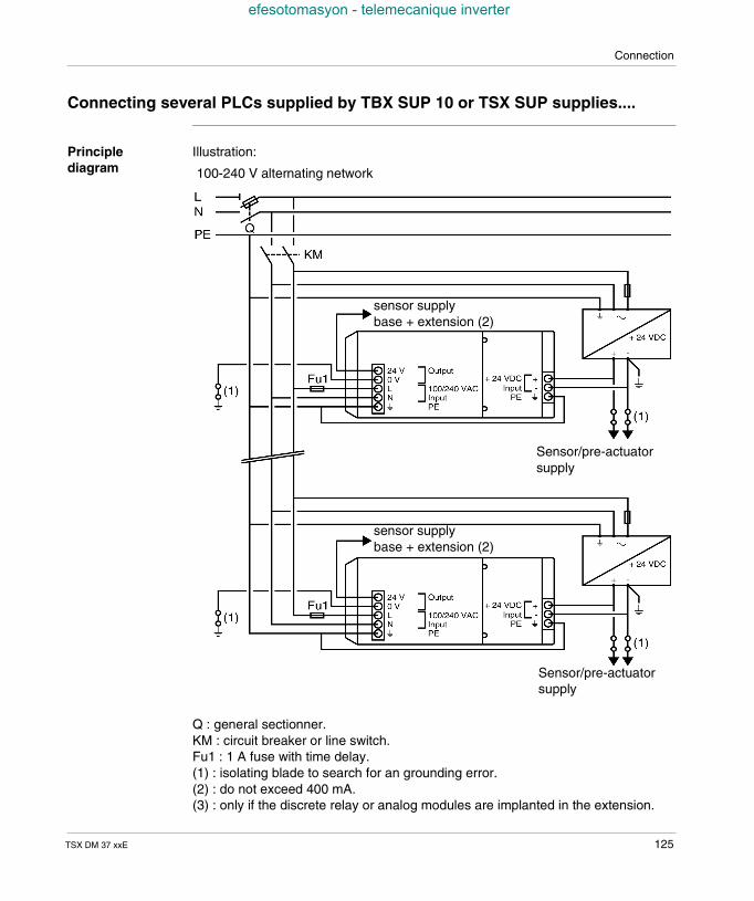
Connection
efesotomasyon - telemecanique inverter
Connecting several PLCs supplied by TBX SUP 10 or TSX SUP supplies....
Principlediagram
Illustration:
Q : general sectionner.KM : circuit breaker or line switch.Fu1 : 1 A fuse with time delay.(1) : isolating blade to search for an grounding error.(2) : do not exceed 400 mA.(3) : only if the discrete relay or analog modules are implanted in the extension.
100-240 V alternating network
sensor supplybase + extension (2)
sensor supplybase + extension (2)
Sensor/pre-actuatorsupply
Sensor/pre-actuatorsupply
TSX DM 37 xxE 125
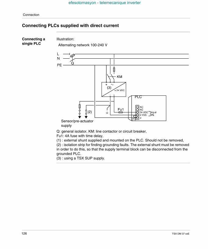
Connection
efesotomasyon - telemecanique inverter
Connecting PLCs supplied with direct current
Connecting asingle PLC
Illustration:
Q: general isolator, KM: line contactor or circuit breaker,Fu1: 4A fuse with time delay,(1) : external shunt supplied and mounted on the PLC. Should not be removed,(2) : isolation strip for finding grounding faults. The external shunt must be removedin order to do this, so that the supply terminal block can be disconnected from thegrounded PLC.(3) : using a TSX SUP supply.
Sensor/pre-actuatorsupply
PLC
Alternating network 100-240 V
126 TSX DM 37 xxE
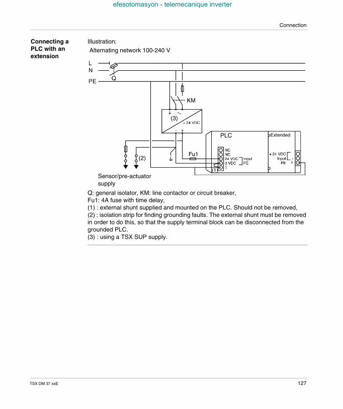
Connection
efesotomasyon - telemecanique inverter
Connecting aPLC with anextension
Illustration:
Q: general isolator, KM: line contactor or circuit breaker,Fu1: 4A fuse with time delay,(1) : external shunt supplied and mounted on the PLC. Should not be removed,(2) : isolation strip for finding grounding faults. The external shunt must be removedin order to do this, so that the supply terminal block can be disconnected from thegrounded PLC.(3) : using a TSX SUP supply.
Alternating network 100-240 V
PLC Extended
Sensor/pre-actuatorsupply
TSX DM 37 xxE 127
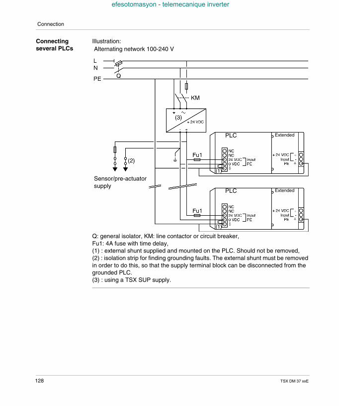
Connection
efesotomasyon - telemecanique inverter
Connectingseveral PLCs
Illustration:
Q: general isolator, KM: line contactor or circuit breaker,Fu1: 4A fuse with time delay,(1) : external shunt supplied and mounted on the PLC. Should not be removed,(2) : isolation strip for finding grounding faults. The external shunt must be removedin order to do this, so that the supply terminal block can be disconnected from thegrounded PLC.(3) : using a TSX SUP supply.
Alternating network 100-240 V
Sensor/pre-actuatorsupply
PLC Extended
PLC Extended
128 TSX DM 37 xxE
Connection
efesotomasyon - telemecanique inverter
Connecting PLC(s) supplied by a continuous floating network (not grounded)
General The TSX 37 PLCs with a 24 VDC network supply do not have primary/secondaryinsulation and the internal 0V is coupled with the mechanical ground connection ofthe PLC. This results in the 0V of the 24VDC network being coupled with the samemechanical ground connection and the particular provisions to be taken for thespecific applications and in particular Applications in a marine environment,which use a "floating" mount.
The only correct way of connecting a TSX 37 (1) PLC to this type of "floating"network is to place an insulated continuous converter (24 VDC/24 VDC) near eachPLC, and use an insulation controller upstream of the converter(s). With this type ofmounting, the first insulation error (i.e. a wire leading one of the floating networkpolarities to the ground connection) is detected by the insulation controller and doesnot produce any error affecting the automatic operation.(1) TSX 37 10 PLC: TSX 3710 128DR1/128DT1/128DTK1/164DTK1TSX 3721/22 PLC: TSX 3721 1../ TSX 3722 1..
TSX DM 37 xxE 129
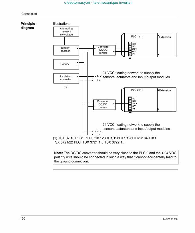
Connection
efesotomasyon - telemecanique inverter
Principlediagram
Illustration:
(1) TSX 37 10 PLC: TSX 3710 128DR1/128DT1/128DTK1/164DTK1TSX 3721/22 PLC: TSX 3721 1../ TSX 3722 1..
Note: The DC/DC converter should be very close to the PLC 2 and the + 24 VDCpolarity wire should be connected in such a way that it cannot accidentally lead tothe ground connection.
Alternatingnetwork
low voltage
Batterycharger
Battery
Insulationcontroller
ConverterDC/DCremote
ConverterDC/DCremote
24 VCC floating network to supply thesensors, actuators and input/output modules
PLC 1 (1) Extension
PLC 2 (1) Extension
24 VCC floating network to supply thesensors, actuators and input/output modules
130 TSX DM 37 xxE
Connection
efesotomasyon - telemecanique inverter
Specific provisions for a continuous floating network
Discrete inputs/outputs
The Discrete inputs/outputs are insulated, the sensor, actuator and discrete input/output module supply should come directly from the floating 24 VDC network.
Counting inputs,built in to theTSX 37 22 1.. PLCbases.
These inputs are insulated; the supply and that of the input’s related sensors shouldcome from the floating 24 VDC network.
Analog inputs/outputs, built into the TSX 37 221.. PLC bases.
These inputs/outputs are not insulated (0V grounded), and should not be usedwith this type or mounting.
In cases where analog inputs/outputs are required, only use analog input/outputmodules (TSX AEZetc./ASZetc.), which are insulated. The sensor supply related toanalog inputs should come from the floating 24 VDC network, with the outputsdelivering a voltage and a current insulated from the ground connection.
Module withrelay outputs
If the modules with relay outputs are built into the PLC, the DC/DC converter shoulddeliver a voltage of 24 VDC +/- 10%.
PLC with a miniextension rack
If the PLC has a mini extension rack, the mini extension rack is not supplied with 24VDC.
Communicationbetween PLCs
Communication links between PLCs: No specific provision. communication via terminal port: insulation is performed by the TSX P ACC01
unit, communication via PCMCIA card: the PCMCIA communication card ensures
insulation.
TSX DM 37 xxE 131
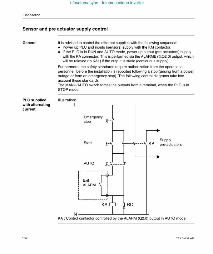
Connection
efesotomasyon - telemecanique inverter
Sensor and pre actuator supply control
General It is advised to control the different supplies with the following sequence: Power up PLC and inputs (sensors) supply with the KM contactor. If the PLC is in RUN and AUTO mode, power up output (pre-actuators) supply
with the KA connector. This is performed via the ALARME (%Q2.0) output, whichwill be relayed (to KA1) if the output is static (continuous supply).
Furthermore, the safety standards require authorization from the operationspersonnel, before the installation is rebooted following a stop (arising from a poweroutage or from an emergency stop). The following control diagrams take intoaccount these standards.The MANU/AUTO switch forces the outputs from a terminal, when the PLC is inSTOP mode.
PLC suppliedwith alternatingcurrent
Illustration:
KA : Control contactor controlled by the ALARM (Q2.0) output in AUTO mode.
Emergencystop
Start
AUTO
ExitALARM
Supplypre-actuators
132 TSX DM 37 xxE
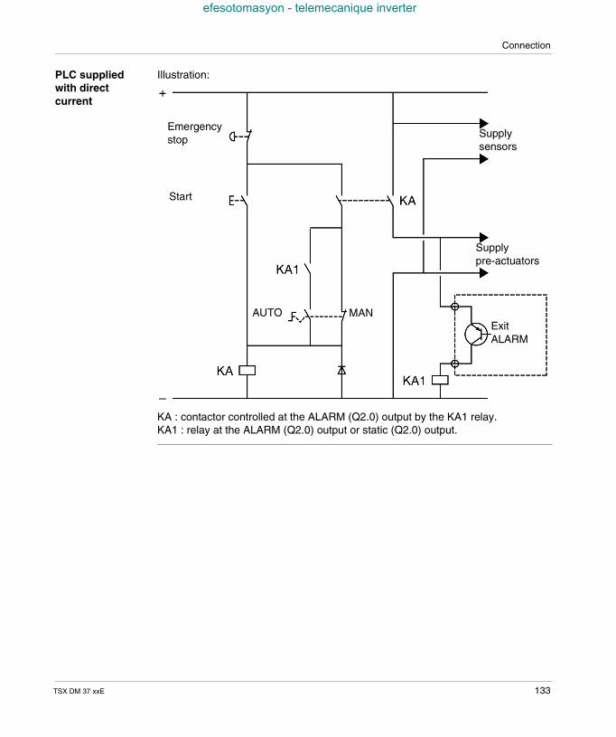
Connection
efesotomasyon - telemecanique inverter
PLC suppliedwith directcurrent
Illustration:
KA : contactor controlled at the ALARM (Q2.0) output by the KA1 relay.KA1 : relay at the ALARM (Q2.0) output or static (Q2.0) output.
Emergencystop
Start
Supplypre-actuators
Supplysensors
ExitALARM
MANAUTO
TSX DM 37 xxE 133

Connection
efesotomasyon - telemecanique inverter
134 TSX DM 37 xxE
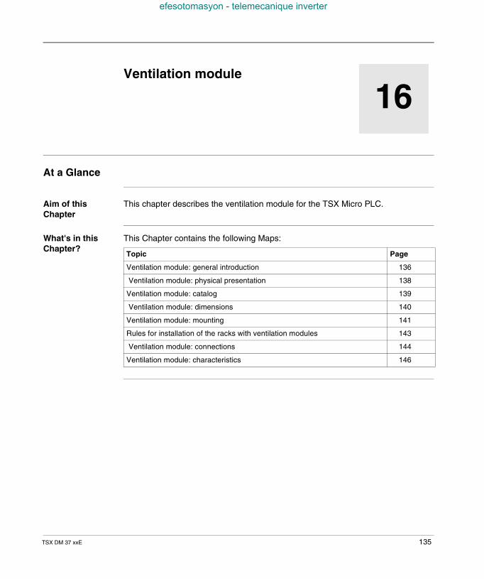
TSX DM 37 xxE
efesotomasyon - telemecanique inverter
16
Ventilation moduleAt a Glance
Aim of thisChapter
This chapter describes the ventilation module for the TSX Micro PLC.
What's in thisChapter?
This Chapter contains the following Maps:
Topic Page
Ventilation module: general introduction 136
Ventilation module: physical presentation 138
Ventilation module: catalog 139
Ventilation module: dimensions 140
Ventilation module: mounting 141
Rules for installation of the racks with ventilation modules 143
Ventilation module: connections 144
Ventilation module: characteristics 146
135
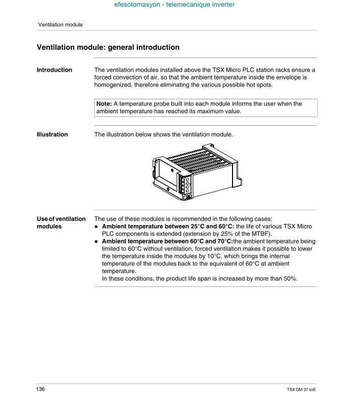
Ventilation module
efesotomasyon - telemecanique inverter
Ventilation module: general introduction
Introduction The ventilation modules installed above the TSX Micro PLC station racks ensure aforced convection of air, so that the ambient temperature inside the envelope ishomogenized, therefore eliminating the various possible hot spots.
Illustration The illustration below shows the ventilation module.
Useof ventilationmodules
The use of these modules is recommended in the following cases: Ambient temperature between 25°C and 60°C: the life of various TSX Micro
PLC components is extended (extension by 25% of the MTBF). Ambient temperature between 60°C and 70°C:the ambient temperature being
limited to 60°C without ventilation, forced ventilation makes it possible to lowerthe temperature inside the modules by 10°C, which brings the internaltemperature of the modules back to the equivalent of 60°C at ambienttemperature.In these conditions, the product life span is increased by more than 50%.
Note: A temperature probe built into each module informs the user when theambient temperature has reached its maximum value.
136 TSX DM 37 xxE
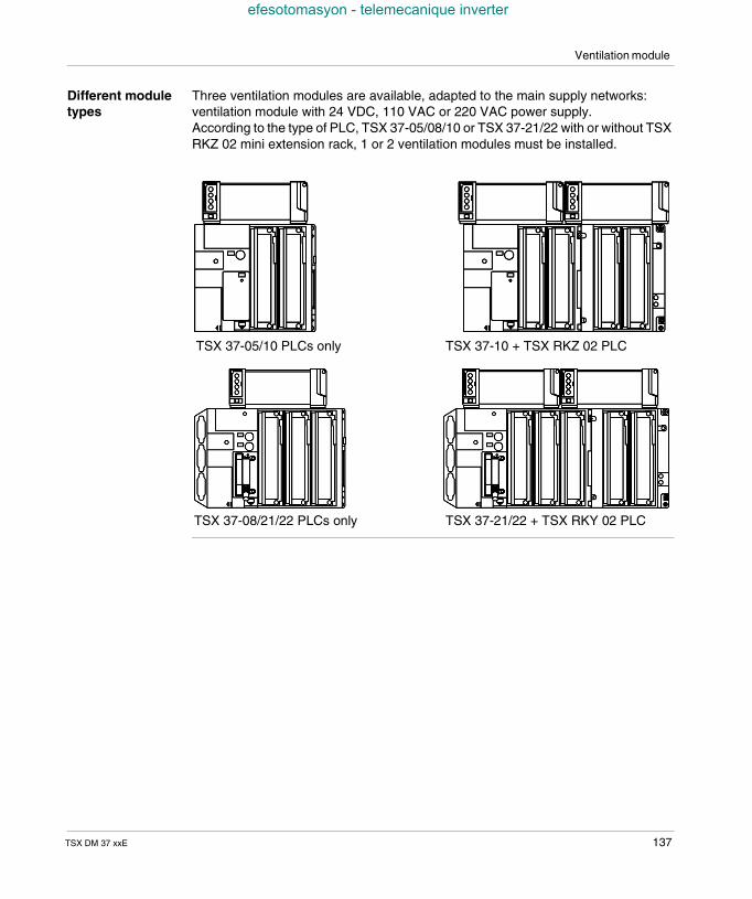
Ventilation module
efesotomasyon - telemecanique inverter
Different moduletypes
Three ventilation modules are available, adapted to the main supply networks:ventilation module with 24 VDC, 110 VAC or 220 VAC power supply.According to the type of PLC, TSX 37-05/08/10 or TSX 37-21/22 with or without TSXRKZ 02 mini extension rack, 1 or 2 ventilation modules must be installed.
TSX 37-05/10 PLCs only TSX 37-10 + TSX RKZ 02 PLC
TSX 37-08/21/22 PLCs only TSX 37-21/22 + TSX RKY 02 PLC
TSX DM 37 xxE 137
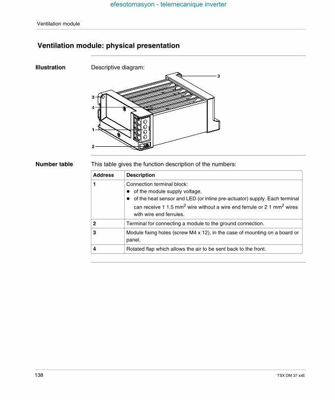
Ventilation module
efesotomasyon - telemecanique inverter
Ventilation module: physical presentation
Illustration Descriptive diagram:
Number table This table gives the function description of the numbers:
Address Description
1 Connection terminal block: of the module supply voltage, of the heat sensor and LED (or inline pre-actuator) supply. Each terminal
can receive 1 1.5 mm2 wire without a wire end ferrule or 2 1 mm2 wireswith wire end ferrules.
2 Terminal for connecting a module to the ground connection.
3 Module fixing holes (screw M4 x 12), in the case of mounting on a board orpanel.
4 Rotated flap which allows the air to be sent back to the front.
138 TSX DM 37 xxE
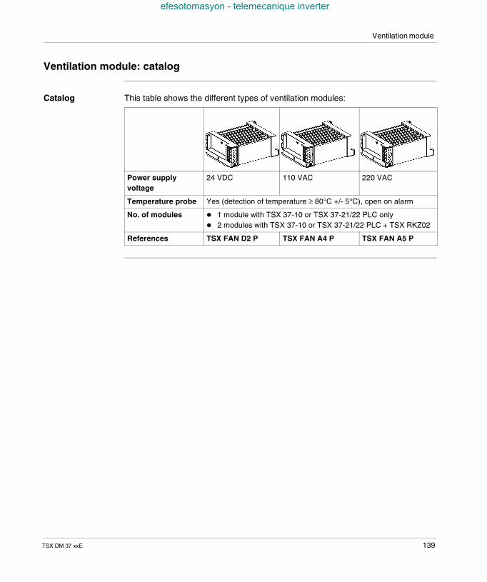
Ventilation module
efesotomasyon - telemecanique inverter
Ventilation module: catalog
Catalog This table shows the different types of ventilation modules:
Power supplyvoltage
24 VDC 110 VAC 220 VAC
Temperature probe Yes (detection of temperature ≥ 80°C +/- 5°C), open on alarm
No. of modules 1 module with TSX 37-10 or TSX 37-21/22 PLC only 2 modules with TSX 37-10 or TSX 37-21/22 PLC + TSX RKZ02
References TSX FAN D2 P TSX FAN A4 P TSX FAN A5 P
TSX DM 37 xxE 139
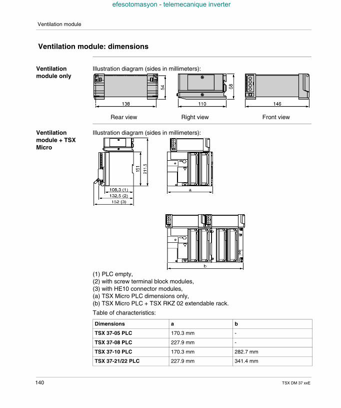
Ventilation module
efesotomasyon - telemecanique inverter
Ventilation module: dimensions
Ventilationmodule only
Illustration diagram (sides in millimeters):
Ventilationmodule + TSXMicro
Illustration diagram (sides in millimeters):
(1) PLC empty,(2) with screw terminal block modules,(3) with HE10 connector modules,(a) TSX Micro PLC dimensions only,(b) TSX Micro PLC + TSX RKZ 02 extendable rack.
Table of characteristics:
Rear view Right view Front view
Dimensions a b
TSX 37-05 PLC 170.3 mm -
TSX 37-08 PLC 227.9 mm -
TSX 37-10 PLC 170.3 mm 282.7 mm
TSX 37-21/22 PLC 227.9 mm 341.4 mm
140 TSX DM 37 xxE
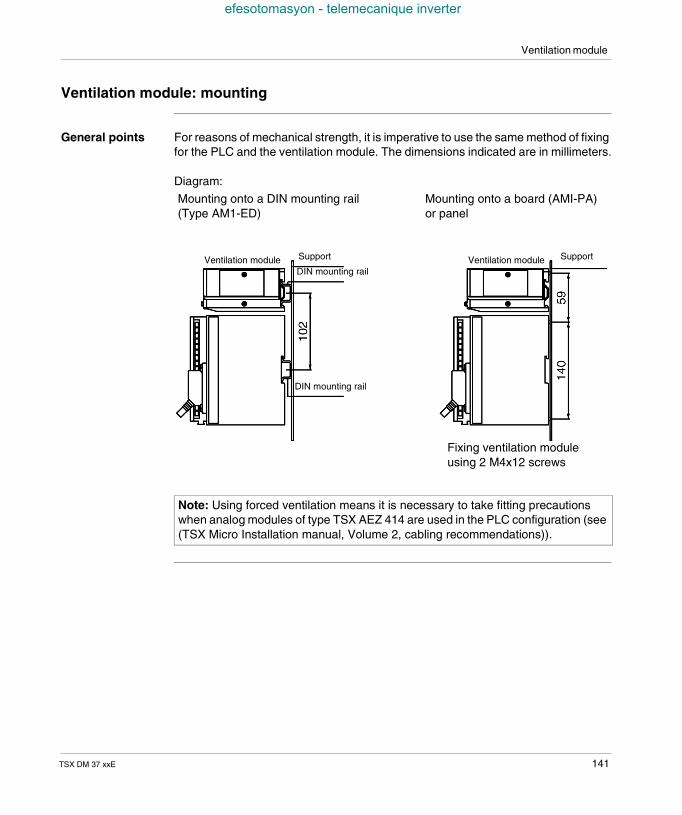
Ventilation module
efesotomasyon - telemecanique inverter
Ventilation module: mounting
General points For reasons of mechanical strength, it is imperative to use the same method of fixingfor the PLC and the ventilation module. The dimensions indicated are in millimeters.
Diagram:
Note: Using forced ventilation means it is necessary to take fitting precautionswhen analog modules of type TSX AEZ 414 are used in the PLC configuration (see(TSX Micro Installation manual, Volume 2, cabling recommendations)).
Mounting onto a DIN mounting rail(Type AM1-ED)
Ventilation module Ventilation moduleSupport Support
DIN mounting rail
DIN mounting rail
Fixing ventilation moduleusing 2 M4x12 screws
Mounting onto a board (AMI-PA)or panel
TSX DM 37 xxE 141
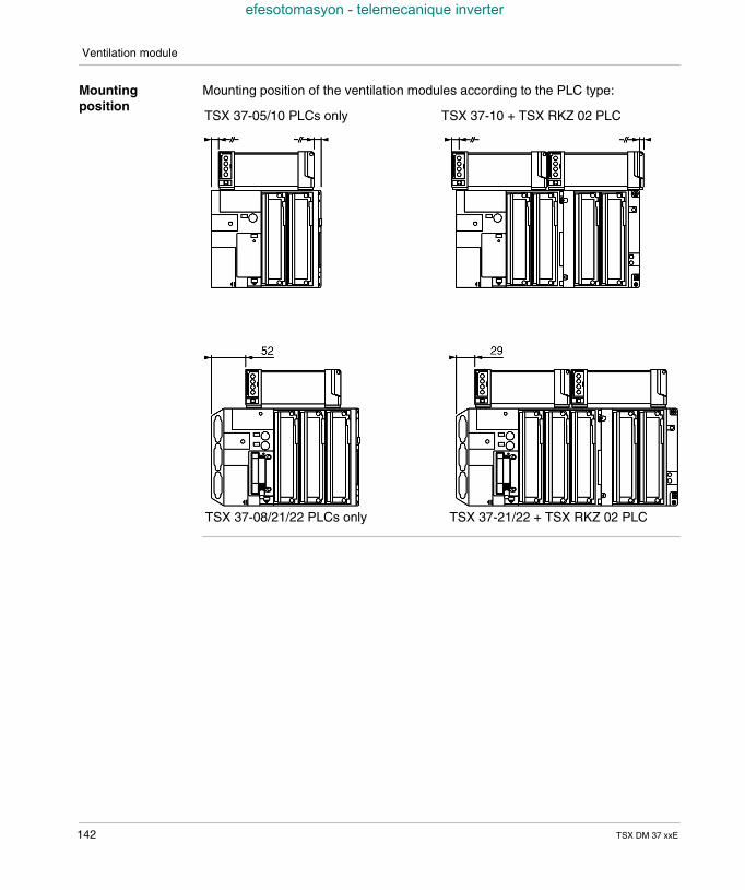
Ventilation module
efesotomasyon - telemecanique inverter
Mountingposition
Mounting position of the ventilation modules according to the PLC type:
TSX 37-05/10 PLCs only TSX 37-10 + TSX RKZ 02 PLC
TSX 37-08/21/22 PLCs only TSX 37-21/22 + TSX RKZ 02 PLC
142 TSX DM 37 xxE
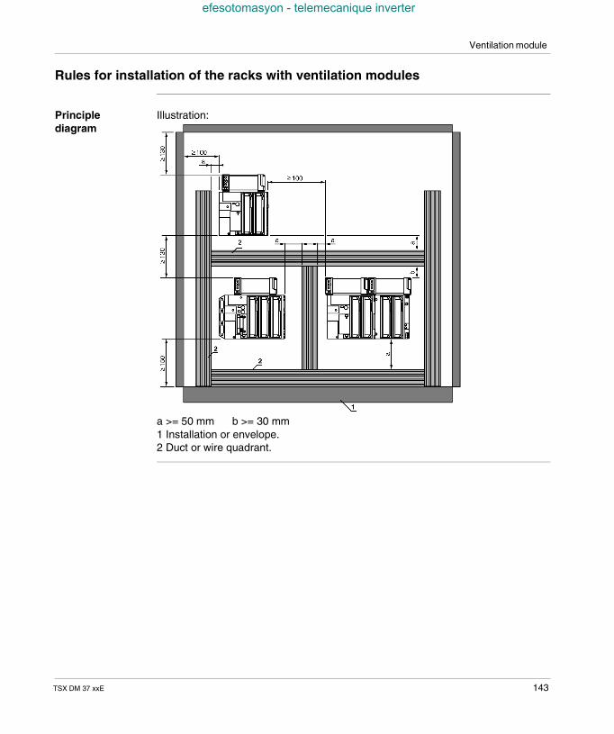
Ventilation module
efesotomasyon - telemecanique inverter
Rules for installation of the racks with ventilation modules
Principlediagram
Illustration:
a >= 50 mm b >= 30 mm1 Installation or envelope.2 Duct or wire quadrant.
TSX DM 37 xxE 143
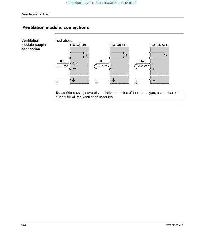
Ventilation module
efesotomasyon - telemecanique inverter
Ventilation module: connections
Ventilationmodule supplyconnection
Illustration:
Note: When using several ventilation modules of the same type, use a sharedsupply for all the ventilation modules.
144 TSX DM 37 xxE
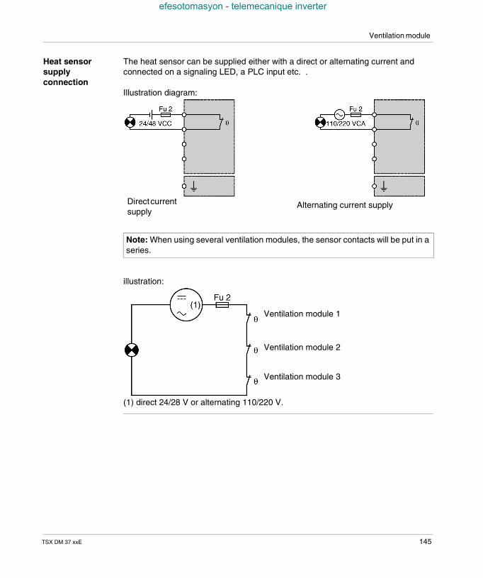
Ventilation module
efesotomasyon - telemecanique inverter
Heat sensorsupplyconnection
The heat sensor can be supplied either with a direct or alternating current andconnected on a signaling LED, a PLC input etc. .
Illustration diagram:
illustration:
(1) direct 24/28 V or alternating 110/220 V.
Note: When using several ventilation modules, the sensor contacts will be put in aseries.
Alternating current supplyDirectcurrentsupply
Ventilation module 1
Ventilation module 2
Ventilation module 3
TSX DM 37 xxE 145
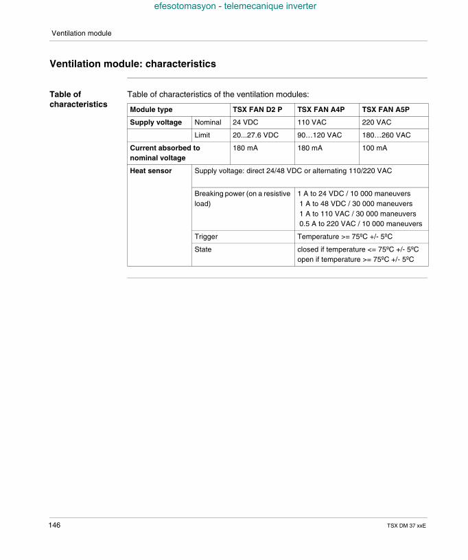
Ventilation module
efesotomasyon - telemecanique inverter
Ventilation module: characteristics
Table ofcharacteristics
Table of characteristics of the ventilation modules:
Module type TSX FAN D2 P TSX FAN A4P TSX FAN A5P
Supply voltage Nominal 24 VDC 110 VAC 220 VAC
Limit 20...27.6 VDC 90…120 VAC 180…260 VAC
Current absorbed tonominal voltage
180 mA 180 mA 100 mA
Heat sensor Supply voltage: direct 24/48 VDC or alternating 110/220 VAC
Breaking power (on a resistiveload)
1 A to 24 VDC / 10 000 maneuvers1 A to 48 VDC / 30 000 maneuvers1 A to 110 VAC / 30 000 maneuvers0.5 A to 220 VAC / 10 000 maneuvers
Trigger Temperature >= 75ºC +/- 5ºC
State closed if temperature <= 75ºC +/- 5ºCopen if temperature >= 75ºC +/- 5ºC
146 TSX DM 37 xxE
TSX DM 37 xxE
efesotomasyon - telemecanique inverter
IV
Commissioning/Diagnostics/MaintenanceAt a Glance
Aim of this Part This part deals with commissioning, diagnostics and maintenance.
What's in thispart?
This Part contains the following Chapters:
Chapter Chaptername Page
17 Display panel 149
18 Display of language objects 169
19 Commissioning 185
20 Maintenance 191
147

Commissioning/Diagnostics/Maintenance
efesotomasyon - telemecanique inverter
148 TSX DM 37 xxE
TSX DM 37 xxE
efesotomasyon - telemecanique inverter
17
Display panelAt a Glance
Aim of thisChapter
This chapter deals with the display panel for the TSX Micro PLCs.
What's in thisChapter?
This Chapter contains the following Maps:
Topic Page
Introduction 150
PLC status display 152
Local input/output status display 154
64 channel modules display 156
Sequencing of the displays 158
Display of faulty local inputs/outputs 159
Display of remote inputs/outputs on the AS-i bus 161
Display of the presence of each slave on the AS-i bus (R I/O mode - DIAG) 162
Display of the status of the input/output bits for each slave (R I/O mode) 164
Incrementation of the slave number in ascending or descending order 166
Specific standard functions 167
Management of the battery LED (BAT) 168
149
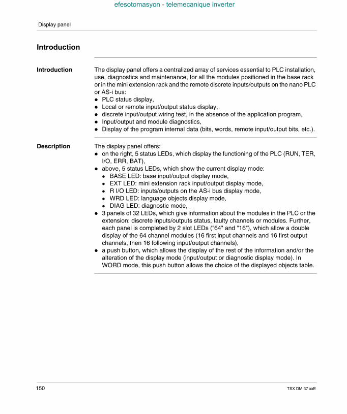
Display panel
efesotomasyon - telemecanique inverter
Introduction
Introduction The display panel offers a centralized array of services essential to PLC installation,use, diagnostics and maintenance, for all the modules positioned in the base rackor in the mini extension rack and the remote discrete inputs/outputs on the nano PLCor AS-i bus: PLC status display, Local or remote input/output status display, discrete input/output wiring test, in the absence of the application program, Input/output and module diagnostics, Display of the program internal data (bits, words, remote input/output bits, etc.).
Description The display panel offers: on the right, 5 status LEDs, which display the functioning of the PLC (RUN, TER,
I/O, ERR, BAT), above, 5 status LEDs, which show the current display mode:
BASE LED: base input/output display mode, EXT LED: mini extension rack input/output display mode, R I/O LED: inputs/outputs on the AS-i bus display mode, WRD LED: language objects display mode, DIAG LED: diagnostic mode,
3 panels of 32 LEDs, which give information about the modules in the PLC or theextension: discrete inputs/outputs status, faulty channels or modules. Further,each panel is completed by 2 slot LEDs ("64" and "16"), which allow a doubledisplay of the 64 channel modules (16 first input channels and 16 first outputchannels, then 16 following input/output channels),
a push button, which allows the display of the rest of the information and/or thealteration of the display mode (input/output or diagnostic display mode). InWORD mode, this push button allows the choice of the displayed objects table.
150 TSX DM 37 xxE
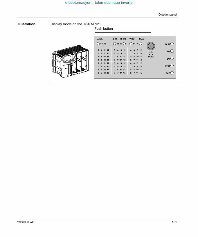
Display panel
efesotomasyon - telemecanique inverter
Illustration Display mode on the TSX Micro:Push button
TSX DM 37 xxE 151
Display panel
efesotomasyon - telemecanique inverter
PLC status display
Introduction The display uses the 5 LEDs RUN, TER, I/O, ERR and BAT, which by means of theirstatus (LED off, blinking or on) provide information on the operating mode of thePLC:
Description this table describes the PLC status for each of the LEDs:
DisplayLED
Status
RUN this LED (green) is lit to indicate that the PLC is in RUN mode, and flashes toindicate that it is in STOP mode. This LED is off when there is no validapplication in the PLC or when there is a fault.
TER this LED (yellow) is lit to show that information is being exchanged by theterminal link. Traffic via the terminal port may appear to make this LED flash.
I/O this LED (red) is lit to show a fault relating to the inputs/outputs: supply fault or at least one channel tripped, module missing, not configured or out of service.For more information on the errors shown by the I/O LED (faulty channel ormodule), the push button must be depressed for more than one second to goto diagnostics mode (See Display of remote inputs/outputs on the AS-i bus,p. 161).
ERR this LED (red) is lit to show a PLC "CPU fault": This LED flashes when there isno valid application in the PLC or if there is a "blocking fault (See Researchingthe errors from PLC status monitors., p. 192)" in the application program.
BAT this LED (red) is lit to show that the battery is defective or missing (optional).This battery, which is used to back up the RAM, must be changed inaccordance with the proper procedure (see Inserting/changing the battery,p. 110).
If the %S66 bit system is at 1, the lighting of this LED is inhibited.
152 TSX DM 37 xxE
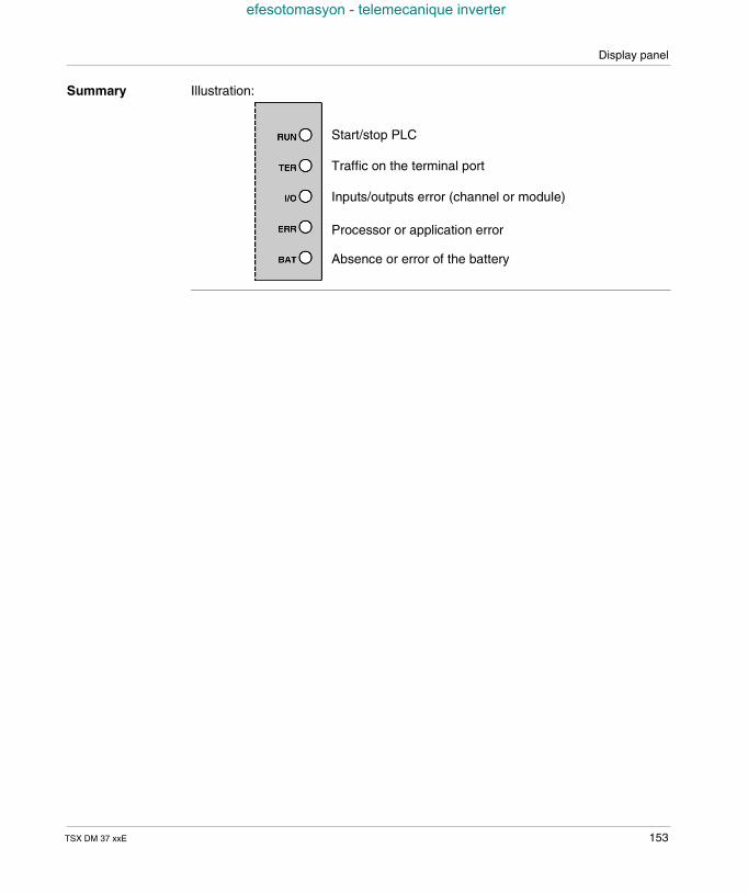
Display panel
efesotomasyon - telemecanique inverter
Summary Illustration:
Start/stop PLC
Traffic on the terminal port
Inputs/outputs error (channel or module)
Processor or application error
Absence or error of the battery
TSX DM 37 xxE 153
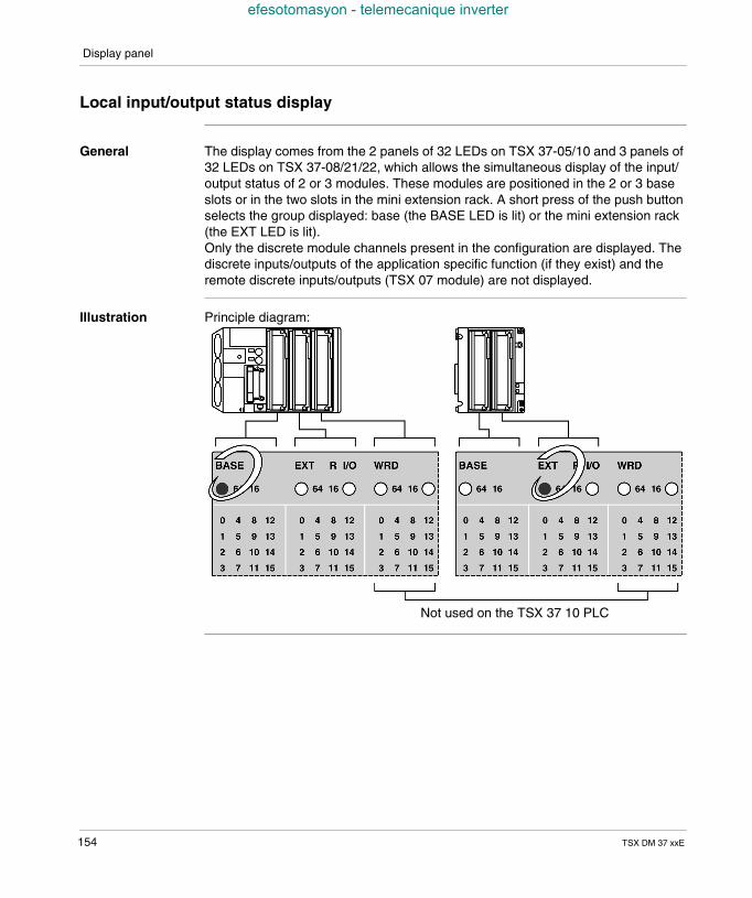
Display panel
efesotomasyon - telemecanique inverter
Local input/output status display
General The display comes from the 2 panels of 32 LEDs on TSX 37-05/10 and 3 panels of32 LEDs on TSX 37-08/21/22, which allows the simultaneous display of the input/output status of 2 or 3 modules. These modules are positioned in the 2 or 3 baseslots or in the two slots in the mini extension rack. A short press of the push buttonselects the group displayed: base (the BASE LED is lit) or the mini extension rack(the EXT LED is lit).Only the discrete module channels present in the configuration are displayed. Thediscrete inputs/outputs of the application specific function (if they exist) and theremote discrete inputs/outputs (TSX 07 module) are not displayed.
Illustration Principle diagram:
Not used on the TSX 37 10 PLC
154 TSX DM 37 xxE
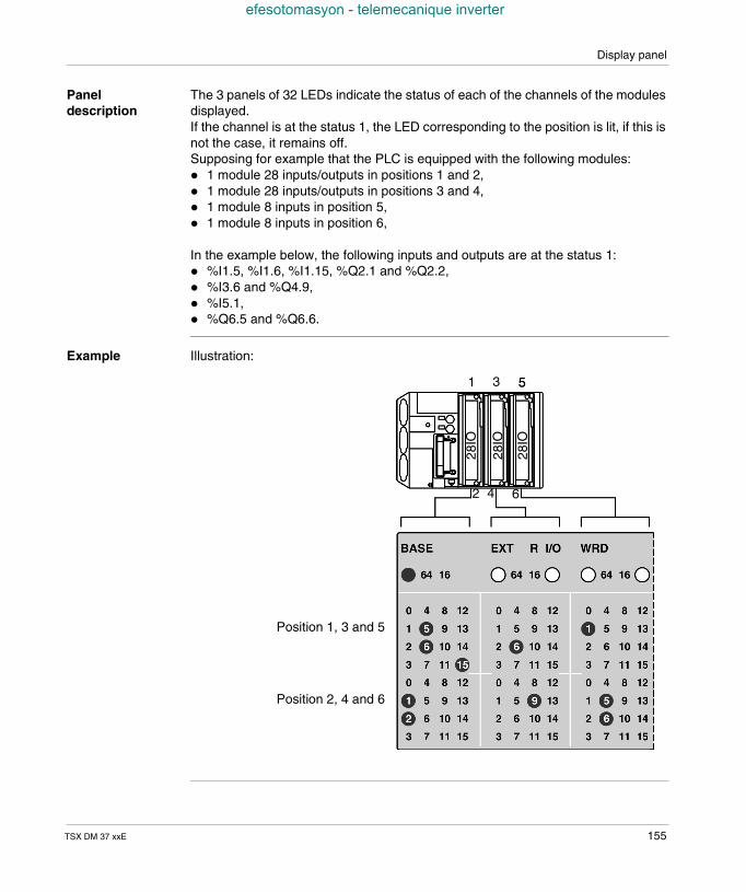
Display panel
efesotomasyon - telemecanique inverter
Paneldescription
The 3 panels of 32 LEDs indicate the status of each of the channels of the modulesdisplayed.If the channel is at the status 1, the LED corresponding to the position is lit, if this isnot the case, it remains off.Supposing for example that the PLC is equipped with the following modules: 1 module 28 inputs/outputs in positions 1 and 2, 1 module 28 inputs/outputs in positions 3 and 4, 1 module 8 inputs in position 5, 1 module 8 inputs in position 6,
In the example below, the following inputs and outputs are at the status 1: %I1.5, %I1.6, %I1.15, %Q2.1 and %Q2.2, %I3.6 and %Q4.9, %I5.1, %Q6.5 and %Q6.6.
Example Illustration:
28IO
28IO
28IO
Position 1, 3 and 5
Position 2, 4 and 6
1 3 5
2 4 6
5
TSX DM 37 xxE 155
Display panel
efesotomasyon - telemecanique inverter
64 channel modules display
General The 64 channel modules, which cannot be displayed together are shown by slotlevel (the "64" LED is lit). A short press on the push button displays either the first16 inputs and the first 16 outputs (only the "64" LED is lit), or the following 16 inputsand the following 16 outputs (the "64" and "16" LEDs are lit).
156 TSX DM 37 xxE
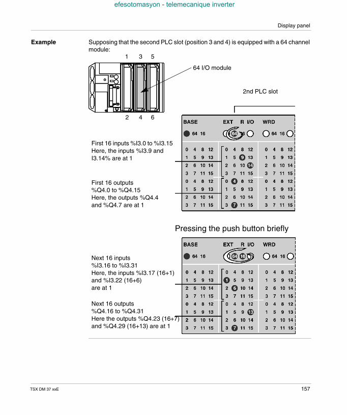
Display panel
efesotomasyon - telemecanique inverter
Example Supposing that the second PLC slot (position 3 and 4) is equipped with a 64 channelmodule:
1 3 5
2 4 6
64 I/O module
2nd PLC slot
First 16 inputs %I3.0 to %I3.15Here, the inputs %I3.9 andI3.14% are at 1
First 16 outputs%Q4.0 to %Q4.15Here, the outputs %Q4.4and %Q4.7 are at 1
Next 16 inputs%I3.16 to %I3.31Here, the inputs %I3.17 (16+1)and %I3.22 (16+6)are at 1
Next 16 outputs%Q4.16 to %Q4.31Here the outputs %Q4.23 (16+7)and %Q4.29 (16+13) are at 1
Pressing the push button briefly
TSX DM 37 xxE 157
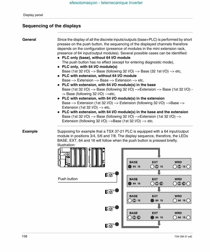
Display panel
efesotomasyon - telemecanique inverter
Sequencing of the displays
General Since the display of all the discrete inputs/outputs (base+PLC) is performed by shortpresses on the push button, the sequencing of the displayed channels thereforedepends on the configuration (presence of modules in the mini extension rack,presence of 64 input/output modules). Several possible cases can be identified: PLC only (base), without 64 I/O module
The push button has no effect (except for entering diagnostic mode), PLC only, with 64 I/O module(s)
Base (1st 32 I/O) --> Base (following 32 I/O) --> Base (32 1st I/O) --> etc, PLC with extension, without 64 I/O module
Base --> Extension --> Base --> Extension --> etc, PLC with extension, with 64 I/O module(s) in the base
Base (1st 32 I/O) --> Base (following 32 I/O) -->Extension --> Base (1st 32 I/O) --> Base (following 32 I/O) -->etc,
PLC with extension, with 64 I/O module(s) in the extensionBase --> Extension (1st 32 I/O) --> Extension (following 32 I/O) -->Base -->Extension (1st 32 I/O) --> etc,
PLC with extension, with 64 I/O module(s) in the base and the extensionBase (1st 32 I/O) --> Base (following 32 I/O) -->Extension (1st 32 I/O) -->Extension (following 32 I/O) -->Base (1st 32 I/O) --> etc.
Example Supposing for example that a TSX 37-21 PLC is equipped with a 64 input/outputmodule in positions 3/4, 5/6 and 7/8. The display sequence, therefore, the LEDsBASE, EXT, 64 and 16 will follow when the push button is pressed briefly.Illustration:
Push button
158 TSX DM 37 xxE
Display panel
efesotomasyon - telemecanique inverter
Display of faulty local inputs/outputs
General The faults are displayed in diagnostic mode, accessed by a long press on the pushbutton (more than 1 second). The DIAG LED, which signals this mode, is thereforelit.
Principle The faulty inputs/outputs and/or modules are displayed by 3 panels of 32 LEDs: if an input or output is faulty (defective power supply, output tripped, etc.), the
associated LED flashes rapidly, if a module is faulty (absent module, module not configured properly, module out
of service, etc.), all the corresponding LEDs flash slowly: 16 LEDs for a half-size module (top or bottom of a display panel), 32 LEDs for a standard size module with 28 inputs/outputs (entire display zone
of the module), 64 LEDs for a standard size module with 64 inputs/outputs (entire display zone
of the module with the 64 only or 64 and 16 LEDs).
All the input/output faults are displayed by short presses on the push button, with thesame sequences as with the input/output status display mode. A long press of thepush button returns to the input/output status display.
Note: Contrary to the input/output status display mode, which is only accessible forthe discrete modules, the diagnostic mode displays the faulty channels associatedwith the analog and counting modules. For example, if a PLC contains a TSX CTZ2A module in position 3, a fault with the counting channel 0 is signaled by a rapidblinking of LED 0 on the upper part of the corresponding zone.
TSX DM 37 xxE 159
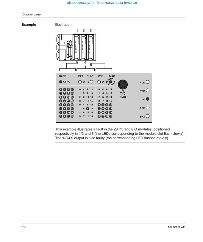
Display panel
efesotomasyon - telemecanique inverter
Example Illustration:
This example illustrates a fault in the 28 I/O and 8 O modules, positionedrespectively in 1/2 and 6 (the LEDs corresponding to the module slot flash slowly).The %Q4.9 output is also faulty (the corresponding LED flashes rapidly).
1 3 5
2 46
28ES
28ES
28ES
160 TSX DM 37 xxE
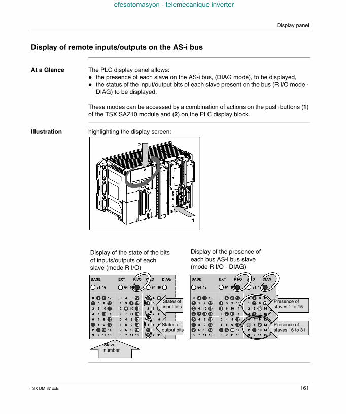
Display panel
efesotomasyon - telemecanique inverter
Display of remote inputs/outputs on the AS-i bus
At a Glance The PLC display panel allows: the presence of each slave on the AS-i bus, (DIAG mode), to be displayed, the status of the input/output bits of each slave present on the bus (R I/O mode -
DIAG) to be displayed.
These modes can be accessed by a combination of actions on the push buttons (1)of the TSX SAZ10 module and (2) on the PLC display block.
Illustration highlighting the display screen:
Display of the state of the bitsof inputs/outputs of eachslave (mode R I/O)
Display of the presence ofeach bus AS-i bus slave(mode R I/O - DIAG)
Slavenumber
States ofinput bits
States ofoutput bits
Presence ofslaves 1 to 15
Presence ofslaves 16 to 31
TSX DM 37 xxE 161
Display panel
efesotomasyon - telemecanique inverter
Display of the presence of each slave on the AS-i bus (R I/O mode - DIAG)
Introduction This mode makes it possible to display: the slaves which have been installed and detected (LEDs permanently on), slaves which have not been installed or detected (LEDs off), slaves which have been installed but not detected or not installed but detected
(LEDs on and blinking).
Procedure foraccess
Carry out the following steps:
Step Action
1 Initial status of display block:local input/output display mode (Base or EXT LEDs on).
2 A short press on the push button (1), of the TSX SAZ module allows the switchto R I/O mode.
3 A long press on the push button (2) on the PLC display block allows the switchto diagnostics mode.The image of the AS-i network is then displayed on the right-hand block, witheach LED representing an address of an AS-i bus slave. All of the ALEDsrepresent the addresses of the slaves 0 to 15, all the B LEDs represent theaddresses 16 to 31 (add + 16 to the figure displayed to get the exact addressof the slave).
4 To return to the initial status: A long press on the push button (2) on the display block (to exit the AS-i
bus diagnostics mode), A short presson the push button (1) on the TSX SAZ module (to return to
local input/output display mode).
162 TSX DM 37 xxE
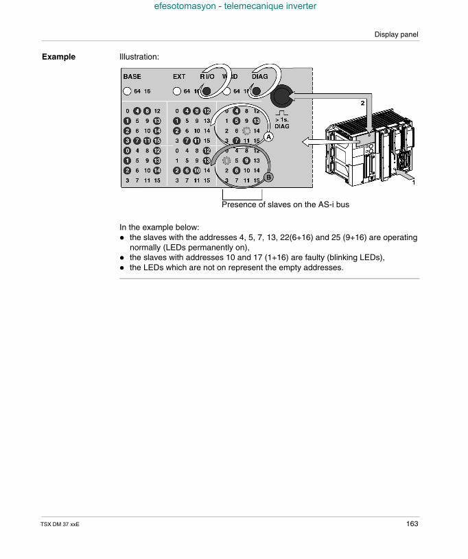
Display panel
efesotomasyon - telemecanique inverter
Example Illustration:
In the example below: the slaves with the addresses 4, 5, 7, 13, 22(6+16) and 25 (9+16) are operating
normally (LEDs permanently on), the slaves with addresses 10 and 17 (1+16) are faulty (blinking LEDs), the LEDs which are not on represent the empty addresses.
Presence of slaves on the AS-i bus
TSX DM 37 xxE 163
Display panel
efesotomasyon - telemecanique inverter
Display of the status of the input/output bits for each slave (R I/O mode)
Introduction The PLC display panel enables the status of the input/output bits of each slave onthe bus to be displayed.
Procedure foraccess
Carry out the following steps:
Step Action
1 Initial status of display panel:local input/output display mode (Base or EXT LEDs on).
2 A short press on the push button (1) on the TSX SAZ 10 module switches toR I/O mode with display: of an address of a slave (1 to 31) on the two panels on the left-hand side
(numerical display), of the status of the input/output bits relating to the slave displayed, on the
panel on the right-hand side (LED on = bit set to 1, LED off = bit set to 0 orno inputs / outputs). The LEDs (0 to 3) at the top show the status of the inputbits of the slave (maximum of 4 input bits per slave); the LEDs (0 to 3) at thebottom show the status of the output bits of the slave (maximum of 4 outputbits per slave),
of the direction of movement in all the slaves, shown by three LEDs beinglit (see Incrementation of the slave number in ascending or descendingorder, p. 166): if LEDs 8,13 and 10 are on, movement in the group of slavestakes place in ascending order; if LEDs 12, 9 and 14 are on, movementtakes place in descending order.
3 Pressing briefly several times in succession on the push button (2) of thecentralized display makes it possible to change the number of the slave inascending order (1 -> 31) or descending order (31 -> 1) depending on thedirection of movement.Changing direction (ascending or descending) is achieved by a long press onthe push button (1) on the TSX SAZ 10 module.
4 Returning to the initial status of the display panel is achieved by a short presson the push button (1) on the TSX SAZ 10 module.
164 TSX DM 37 xxE
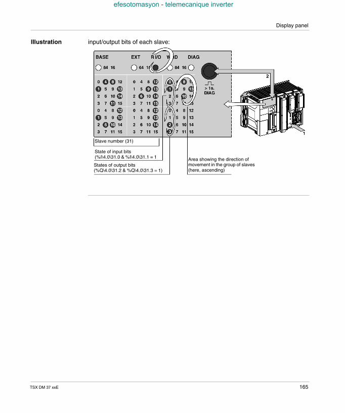
Display panel
efesotomasyon - telemecanique inverter
Illustration input/output bits of each slave:
Slave number (31)
State of input bits(%I\4.0\31.0 & %I\4.0\31.1 = 1
States of output bits(%Q\4.0\31.2 & %Q\4.0\31.3 = 1)
Area showing the direction ofmovement in the group of slaves(here, ascending)
TSX DM 37 xxE 165
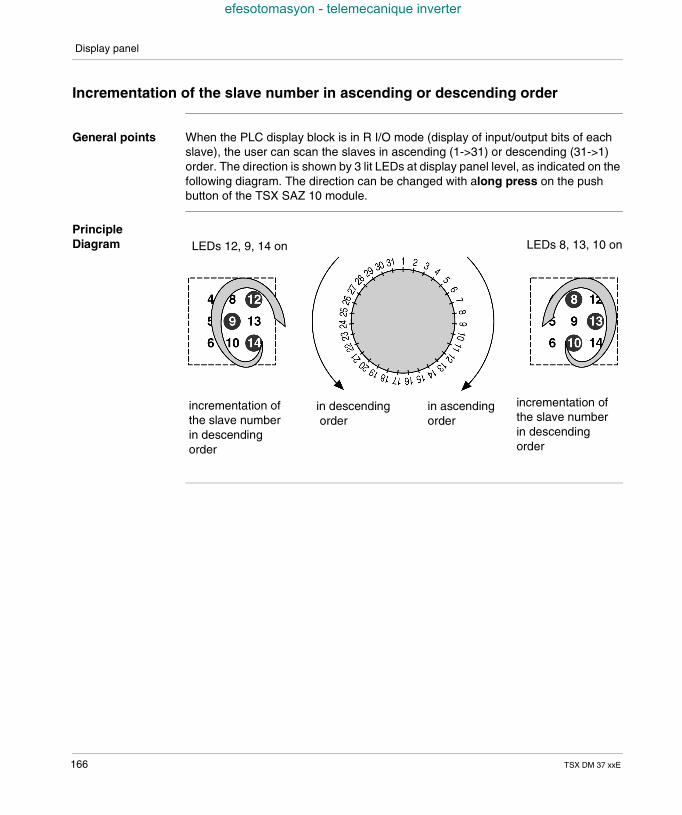
Display panel
efesotomasyon - telemecanique inverter
Incrementation of the slave number in ascending or descending order
General points When the PLC display block is in R I/O mode (display of input/output bits of eachslave), the user can scan the slaves in ascending (1->31) or descending (31->1)order. The direction is shown by 3 lit LEDs at display panel level, as indicated on thefollowing diagram. The direction can be changed with along press on the pushbutton of the TSX SAZ 10 module.
PrincipleDiagram
incrementation ofthe slave numberin descendingorder
incrementation ofthe slave numberin descendingorder
in descendingorder
in ascendingorder
LEDs 12, 9, 14 on LEDs 8, 13, 10 on
166 TSX DM 37 xxE
Display panel
efesotomasyon - telemecanique inverter
Specific standard functions
At a Glance Each TSX 37 PLC and TSX SAZ 10 module features a push button on their frontpanels, enabling the operating mode of the central display unit to be changed. Thediscrete inputs can be used to carry out the same function as these push buttons.By default, any changes to the operating mode of the display block are made by thepush buttons.
Offset pushbutton of thedisplay block
To replace the push button of the central unit with a discrete input, simply: initialize the contents of the %SW99 word by program or by setting at the address
of the required input, validate the function of this input by setting the system bit %S99 to 1, thus
rendering the push button inactive.
The system word %SW99 indicates the geographic address of the discrete inputassigned in place of the push button.By default, the word %SW99 contains the address corresponding to input %I1.10(input 10 of the module located in position 1) as the dedicated input for this function.It is however possible to modify the assignment of the dedicated input for thisfunction by program (see(Reference manual PL7, volume 2, system words)).
Offset pushbutton of themodule AS-i TSXSTZ 10
To replace the push button of the AS-i module with a discrete input, simply: initialize the contents of the %SW98 word by program or by setting at the address
of the required input, validate the function of this input by setting the system bit %S98 to 1, thus
rendering the push button inactive.
The system word %SW98 indicates the geographic address of the discrete inputassigned in place of the push button.By default, the word %SW98 contains the address corresponding to input %I1.11(input 11 of the module located in position 1) as the dedicated input for this function.It is however possible to modify the assignment of the dedicated input for thisfunction by program (see(Reference manual PL7, volume 2, system words)).
TSX DM 37 xxE 167
Display panel
efesotomasyon - telemecanique inverter
Management of the battery LED (BAT)
Principle The switching on of the BAT status LED, which indicates the absence of or an errorin the backup battery, may be inhibited per program or by an adjustment, by settingthe system bit %S66 to 1.The table below describes the different statuses of the %S66 bit.
Bit No. Description
%S66 = 0: BAT LED is on when the back-up battery is absent or faulty.
= 1: BAT LED off.
168 TSX DM 37 xxE
TSX DM 37 xxE
efesotomasyon - telemecanique inverter
18
Display of language objectsAt a Glance
Aim of thisChapter
This chapter deals with the display of language objects.
What's in thisChapter?
This Chapter contains the following Maps:
Topic Page
WORD mode 170
Word of order and status : %SW67 171
Index word : %SW68 173
Word %SW69 175
Example : word display in hexadecimal mode 176
Example : word display in binary mode 178
Example : display of the internal bit status 181
Example: Display of remote inputs/outputs on TSX 07 183
169

Display of language objects
efesotomasyon - telemecanique inverter
WORD mode
General The Display of language objects comes from the 3 panels of 32 LEDs, which allowthe display of the value of 256 bits or 16 words max., when the WORD mode isactivated. The display of the words can be binary, which allows 4 consecutive wordsor hexadecimal alphanumerics to be displayed. In this case, one single word isdisplayed with most/least significant alternation.It is possible to display the %M, %Si or %Xi bits, the %MWi, %SWi or %KWi wordsand the remote discrete inputs/outputs delivered by TSX 07 PLCs.
Principle The WORD mode is activated by setting the %S69 bit system to 1, which is signaledby the WRD LED being lit. In this mode, the push button will scroll the valuedisplayed (most/least significant in the hexadecimal base) or the values displayed(4 words then 4 following words etc. in the binary base).
The installation of the display is performed by the 3 system words %SW67, %SW68and %SW69, which define respectively : the order information and the mode status (type of objects displayed, display
base etc.), the current index of the displayed objects (64 bit group number or word order in
the table defined by the maximum index and the word %SW69) and the maximumindex (number of words in the word table),
the number of the first word in the word table.
Illustration Principle diagram:
Error
Most significant display Least significant display
Direction of movement
Binary/hexadecimal
Reserved Type of object
maximum index Current index
Number of first object
170 TSX DM 37 xxE
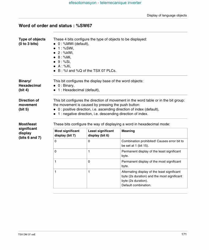
Display of language objects
efesotomasyon - telemecanique inverter
Word of order and status : %SW67
Type of objects(0 to 3 bits)
These 4 bits configure the type of objects to be displayed: 0 : %MWi (default), 1 : %SWi, 2 : %kWi, 8 : %Mi, 9 : %Si, A : %Xi, B : %I and %Q of the TSX 07 PLCs.
Binary/Hexadecimal(bit 4)
This bit configures the display base of the word objects: 0 : Binary, 1 : Hexadecimal (default),
Direction ofmovement(bit 5)
This bit configures the direction of movement in the word table or in the bit group:the movement is caused by pressing the push button: 0 : positive direction, i.e. ascending direction of index (default), 1 : negative direction, i.e. descending direction of index.
Most/leastsignificantdisplay(bits 6 and 7)
These bits configure the way of displaying a word in hexadecimal mode:
Most significantdisplay (bit 7)
Least significantdisplay (bit 6)
Meaning
0 0 Combination prohibited! Causes error bit tobe set at 1 (bit 15).
0 1 Permanent display of the least significantbyte.
1 0 Permanent display of the most significantbyte.
1 1 Alternating display of the least significantbyte (2s duration) and the most significantbyte (2s duration).Default combination.
TSX DM 37 xxE 171
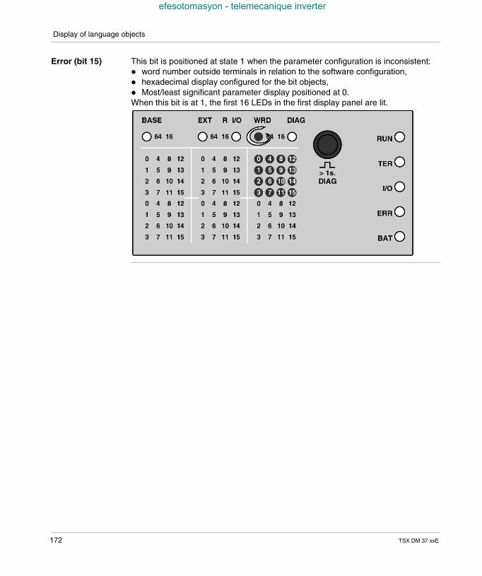
Display of language objects
efesotomasyon - telemecanique inverter
Error (bit 15) This bit is positioned at state 1 when the parameter configuration is inconsistent: word number outside terminals in relation to the software configuration, hexadecimal display configured for the bit objects, Most/least significant parameter display positioned at 0.When this bit is at 1, the first 16 LEDs in the first display panel are lit.
172 TSX DM 37 xxE
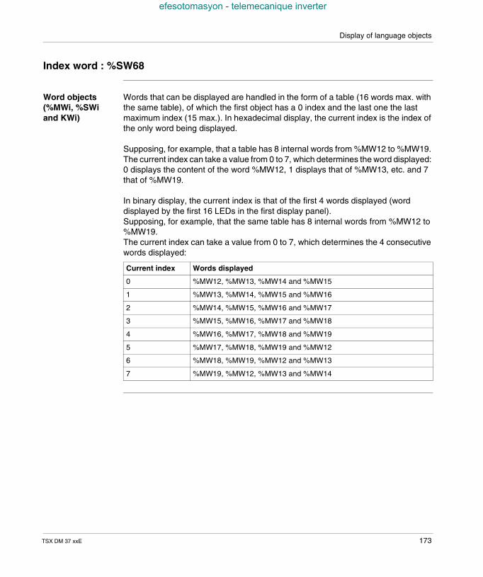
Display of language objects
efesotomasyon - telemecanique inverter
Index word : %SW68
Word objects(%MWi, %SWiand KWi)
Words that can be displayed are handled in the form of a table (16 words max. withthe same table), of which the first object has a 0 index and the last one the lastmaximum index (15 max.). In hexadecimal display, the current index is the index ofthe only word being displayed.
Supposing, for example, that a table has 8 internal words from %MW12 to %MW19.The current index can take a value from 0 to 7, which determines the word displayed:0 displays the content of the word %MW12, 1 displays that of %MW13, etc. and 7that of %MW19.
In binary display, the current index is that of the first 4 words displayed (worddisplayed by the first 16 LEDs in the first display panel).Supposing, for example, that the same table has 8 internal words from %MW12 to%MW19.The current index can take a value from 0 to 7, which determines the 4 consecutivewords displayed:
Current index Words displayed
0 %MW12, %MW13, %MW14 and %MW15
1 %MW13, %MW14, %MW15 and %MW16
2 %MW14, %MW15, %MW16 and %MW17
3 %MW15, %MW16, %MW17 and %MW18
4 %MW16, %MW17, %MW18 and %MW19
5 %MW17, %MW18, %MW19 and %MW12
6 %MW18, %MW19, %MW12 and %MW13
7 %MW19, %MW12, %MW13 and %MW14
TSX DM 37 xxE 173
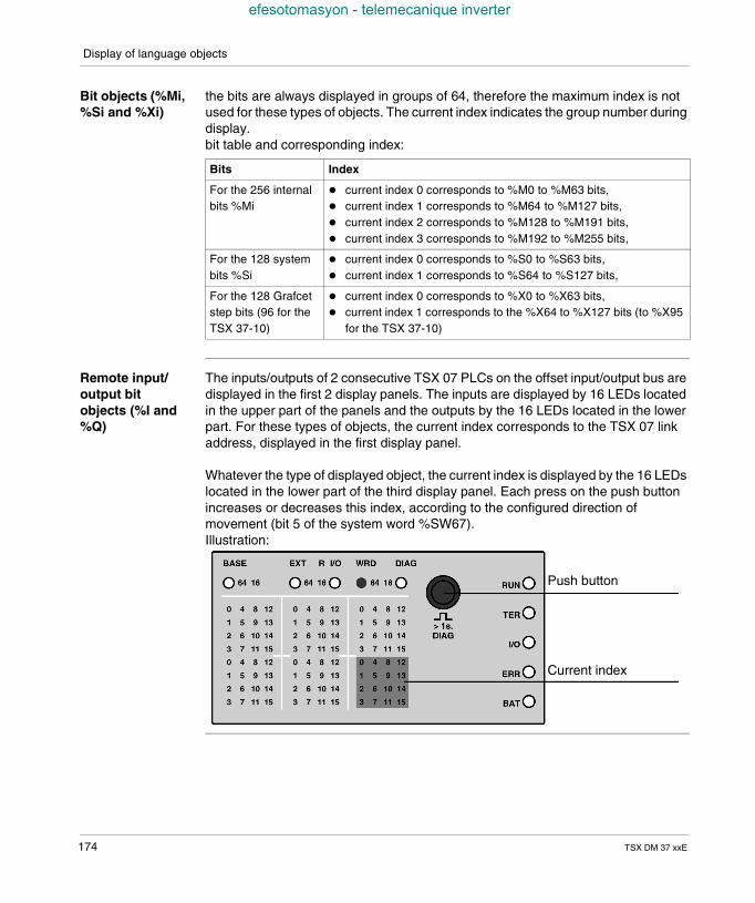
Display of language objects
efesotomasyon - telemecanique inverter
Bit objects (%Mi,%Si and %Xi)
the bits are always displayed in groups of 64, therefore the maximum index is notused for these types of objects. The current index indicates the group number duringdisplay.bit table and corresponding index:
Remote input/output bitobjects (%I and%Q)
The inputs/outputs of 2 consecutive TSX 07 PLCs on the offset input/output bus aredisplayed in the first 2 display panels. The inputs are displayed by 16 LEDs locatedin the upper part of the panels and the outputs by the 16 LEDs located in the lowerpart. For these types of objects, the current index corresponds to the TSX 07 linkaddress, displayed in the first display panel.
Whatever the type of displayed object, the current index is displayed by the 16 LEDslocated in the lower part of the third display panel. Each press on the push buttonincreases or decreases this index, according to the configured direction ofmovement (bit 5 of the system word %SW67).Illustration:
Bits Index
For the 256 internalbits %Mi
current index 0 corresponds to %M0 to %M63 bits, current index 1 corresponds to %M64 to %M127 bits, current index 2 corresponds to %M128 to %M191 bits, current index 3 corresponds to %M192 to %M255 bits,
For the 128 systembits %Si
current index 0 corresponds to %S0 to %S63 bits, current index 1 corresponds to %S64 to %S127 bits,
For the 128 Grafcetstep bits (96 for theTSX 37-10)
current index 0 corresponds to %X0 to %X63 bits, current index 1 corresponds to the %X64 to %X127 bits (to %X95
for the TSX 37-10)
Push button
Current index
174 TSX DM 37 xxE
Display of language objects
efesotomasyon - telemecanique inverter
Word %SW69
General points Contains the number of the first word of the table, i.e. the number of the first word tobe displayed. Remember that a maximum of 16 words can be displayed, with 4words displayed simultaneously in binary mode and one single word displayed inhexadecimal mode. To facilitate identification of the word(s) currently beingdisplayed, you are advised to choose a first word, whose address is 0 or a multipleof 10.The first word currently being displayed is defined by the current index (see Indexword : %SW68, p. 173).The word %SW69 is not used with bit objects.
Value of thesystem words%SW67 to%SW69 uponactivating WORDmode
following a prior mode deactivation (setting %S69 bit to 0)Deactivation of WORD mode does not alter the content of the 3 system words.Upon reactivation (setting %S69 to 1), the system words %SW67 to %SW69revert to their value at the time of the last mode deactivation. You are howeveradvised to reinitialize the current index each time you enter the mode, in order toavoid uncertainty caused by an accidental press on the push button.
after a warm startThe 3 system words revert to their value at the time of the power failure.
after a cold startThe 3 system words are initialized to the following values: %SW67 = H’xxD0’ -> display of the internal words %MW in hexadecimal
mode, alternating between the most and least significant. Movement in thetable is performed via incrementation,
%SW68 = H’0F00’ -> display of the index word 0 and movement to index word15, by pressing the push button,
%SW69 = H’0000’ -> the first word in the table has the number 0 (%MW0).by default and without any special programming, it is possible to display the contentof the internal words %MW0 to %MW15.
TSX DM 37 xxE 175
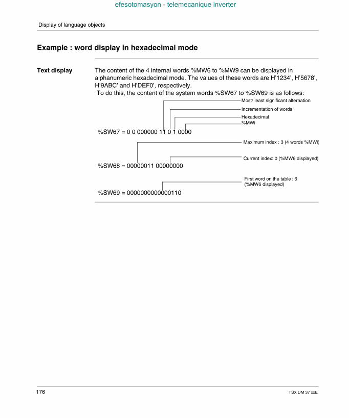
Display of language objects
efesotomasyon - telemecanique inverter
Example : word display in hexadecimal mode
Text display The content of the 4 internal words %MW6 to %MW9 can be displayed inalphanumeric hexadecimal mode. The values of these words are H’1234’, H’5678’,H’9ABC’ and H’DEF0’, respectively.To do this, the content of the system words %SW67 to %SW69 is as follows:
%SW67 = 0 0 000000 11 0 1 0000
Most/ least significant alternation
Incrementation of words
Hexadecimal%MWi
%SW68 = 00000011 00000000
Maximum index : 3 (4 words %MWi)
Current index: 0 (%MW6 displayed)
%SW69 = 0000000000000110
First word on the table : 6(%MW6 displayed)
176 TSX DM 37 xxE
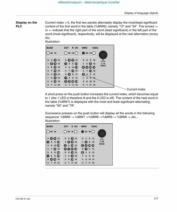
Display of language objects
efesotomasyon - telemecanique inverter
Display on thePLC
Current index = 0, the first two panels alternately display the most/least significantcontent of the first word in the table (%MW6); namely "12" and "34". The arrows ->or <- indicate that the right part of the word (least significant) or the left part of theword (most significant), respectively, will be displayed at the next alternation (every2s).Illustration:
A short press on the push button increases the current index, which becomes equalto 1 (the 1 LED is therefore lit and the 0 LED is off). The content of the next word inthe table (%MW7) is displayed with the most and least significant alternating,namely "56" and "78".
Successive presses on the push button will display all the words in the followingsequence: %MW6 -> %MW7 ->%MW8 ->%MW9 -> %MW6 -> etc...Illustration:
Current index
TSX DM 37 xxE 177
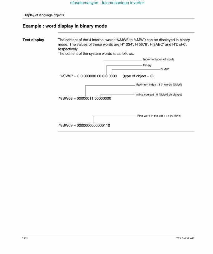
Display of language objects
efesotomasyon - telemecanique inverter
Example : word display in binary mode
Text display The content of the 4 internal words %MW6 to %MW9 can be displayed in binarymode. The values of these words are H’1234’, H’5678’, H’9ABC’ and H’DEF0’,respectively.The content of the system words is as follows:
%SW67 = 0 0 000000 00 0 0 0000
Incrementation of words
Binary%MWi
(type of object = 0)
%SW68 = 00000011 00000000
Maximum index : 3 (4 words %MWi)
Indice courant : 0 %MW6 displayed)
%SW69 = 0000000000000110
First word in the table : 6 (%MW6)
178 TSX DM 37 xxE
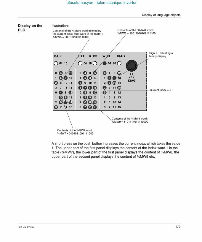
Display of language objects
efesotomasyon - telemecanique inverter
Display on thePLC
Illustration:
A short press on the push button increases the current index, which takes the value1. The upper part of the first panel displays the content of the index word 1 in thetable (%MW7), the lower part of the first panel displays the content of %MW8, theupper part of the second panel displays the content of %MW9 etc.
Contents of the %MW6 word defined bythe current index (first word in the table) :%MW6 = 0001001000110100
Contents of the %MW8 word :%MW8 = 10011010101111100
Sign X, indicating abinary display
Current index = 0
Contents of the %MW9 word :%MW9 = 1101111011110000
Contents of the %MW7 word :%MW7 = 0101011001111000
TSX DM 37 xxE 179
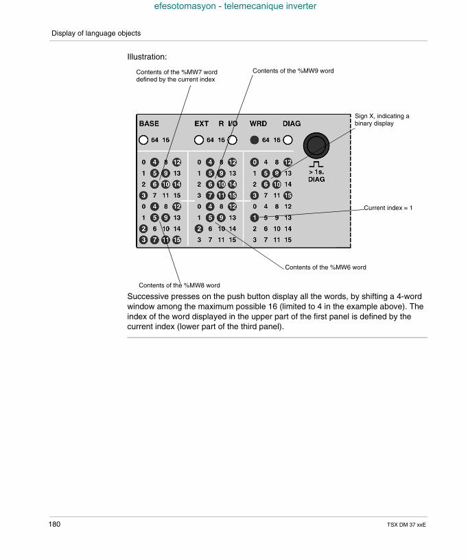
Display of language objects
efesotomasyon - telemecanique inverter
Illustration:
Successive presses on the push button display all the words, by shifting a 4-wordwindow among the maximum possible 16 (limited to 4 in the example above). Theindex of the word displayed in the upper part of the first panel is defined by thecurrent index (lower part of the third panel).
Contents of the %MW7 worddefined by the current index
Contents of the %MW9 word
Sign X, indicating abinary display
Current index = 1
Contents of the %MW6 word
Contents of the %MW8 word
180 TSX DM 37 xxE
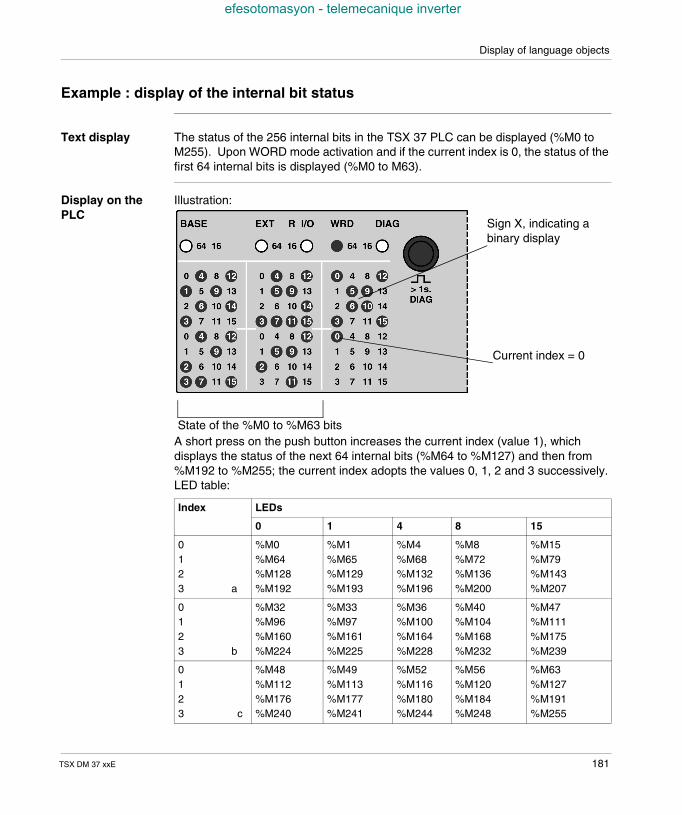
Display of language objects
efesotomasyon - telemecanique inverter
Example : display of the internal bit status
Text display The status of the 256 internal bits in the TSX 37 PLC can be displayed (%M0 toM255). Upon WORD mode activation and if the current index is 0, the status of thefirst 64 internal bits is displayed (%M0 to M63).
Display on thePLC
Illustration:
A short press on the push button increases the current index (value 1), whichdisplays the status of the next 64 internal bits (%M64 to %M127) and then from%M192 to %M255; the current index adopts the values 0, 1, 2 and 3 successively.LED table:
Index LEDs
0 1 4 8 15
0123 a
%M0%M64%M128%M192
%M1%M65%M129%M193
%M4%M68%M132%M196
%M8%M72%M136%M200
%M15%M79%M143%M207
0123 b
%M32%M96%M160%M224
%M33%M97%M161%M225
%M36%M100%M164%M228
%M40%M104%M168%M232
%M47%M111%M175%M239
0123 c
%M48%M112%M176%M240
%M49%M113%M177%M241
%M52%M116%M180%M244
%M56%M120%M184%M248
%M63%M127%M191%M255
Sign X, indicating abinary display
Current index = 0
State of the %M0 to %M63 bits
TSX DM 37 xxE 181
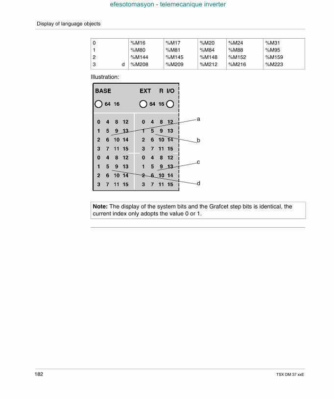
Display of language objects
efesotomasyon - telemecanique inverter
Illustration:
0123 d
%M16%M80%M144%M208
%M17%M81%M145%M209
%M20%M84%M148%M212
%M24%M88%M152%M216
%M31%M95%M159%M223
Note: The display of the system bits and the Grafcet step bits is identical, thecurrent index only adopts the value 0 or 1.
a
b
c
d
182 TSX DM 37 xxE
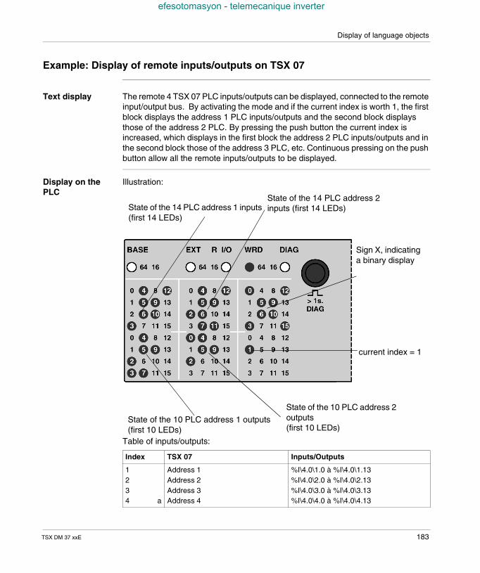
Display of language objects
efesotomasyon - telemecanique inverter
Example: Display of remote inputs/outputs on TSX 07
Text display The remote 4 TSX 07 PLC inputs/outputs can be displayed, connected to the remoteinput/output bus. By activating the mode and if the current index is worth 1, the firstblock displays the address 1 PLC inputs/outputs and the second block displaysthose of the address 2 PLC. By pressing the push button the current index isincreased, which displays in the first block the address 2 PLC inputs/outputs and inthe second block those of the address 3 PLC, etc. Continuous pressing on the pushbutton allow all the remote inputs/outputs to be displayed.
Display on thePLC
Illustration:
Table of inputs/outputs:
Index TSX 07 Inputs/Outputs
1234 a
Address 1Address 2Address 3Address 4
%I\4.0\1.0 à %I\4.0\1.13%I\4.0\2.0 à %I\4.0\2.13%I\4.0\3.0 à %I\4.0\3.13%I\4.0\4.0 à %I\4.0\4.13
State of the 14 PLC address 1 inputs(first 14 LEDs)
State of the 14 PLC address 2inputs (first 14 LEDs)
Sign X, indicatinga binary display
current index = 1
State of the 10 PLC address 1 outputs(first 10 LEDs)
State of the 10 PLC address 2outputs(first 10 LEDs)
TSX DM 37 xxE 183
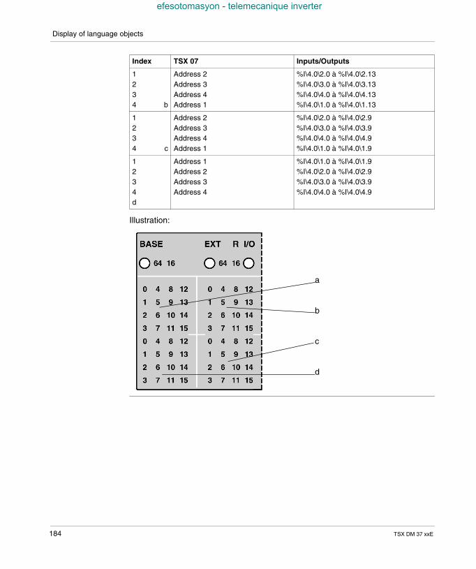
Display of language objects
efesotomasyon - telemecanique inverter
Illustration:
1234 b
Address 2Address 3Address 4Address 1
%I\4.0\2.0 à %I\4.0\2.13%I\4.0\3.0 à %I\4.0\3.13%I\4.0\4.0 à %I\4.0\4.13%I\4.0\1.0 à %I\4.0\1.13
1234 c
Address 2Address 3Address 4Address 1
%I\4.0\2.0 à %I\4.0\2.9%I\4.0\3.0 à %I\4.0\3.9%I\4.0\4.0 à %I\4.0\4.9%I\4.0\1.0 à %I\4.0\1.9
1234d
Address 1Address 2Address 3Address 4
%I\4.0\1.0 à %I\4.0\1.9%I\4.0\2.0 à %I\4.0\2.9%I\4.0\3.0 à %I\4.0\3.9%I\4.0\4.0 à %I\4.0\4.9
Index TSX 07 Inputs/Outputs
a
b
c
d
184 TSX DM 37 xxE
TSX DM 37 xxE
efesotomasyon - telemecanique inverter
19
CommissioningAt a Glance
Aim of thisChapter
This chapter is about the commissioning of the TSX 37 PLCs.
What's in thisChapter?
This Chapter contains the following Maps:
Topic Page
First power-up 186
Description of PLC states 188
185
Commissioning
efesotomasyon - telemecanique inverter
First power-up
Principle When switched on, the PLC carries out its self-tests then places itself on hold for anapplication transfer. The different states of the PLC are signaled at the level of thedisplay block by the RUN, ERR, I/O LEDs. .
186 TSX DM 37 xxE
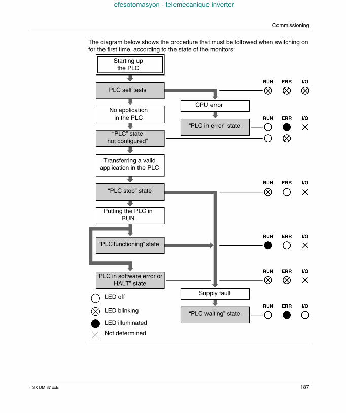
Commissioning
efesotomasyon - telemecanique inverter
The diagram below shows the procedure that must be followed when switching onfor the first time, according to the state of the monitors:
Starting upthe PLC
PLC self tests
No applicationin the PLC
“PLC” statenot configured”
Transferring a validapplication in the PLC
“PLC stop” state
Putting the PLC inRUN
“PLC functioning” state
“PLC in software error orHALT” state
CPU error
“PLC in error” state
Supply fault
“PLC waiting” state
LED off
LED blinking
LED illuminated
Not determined
TSX DM 37 xxE 187
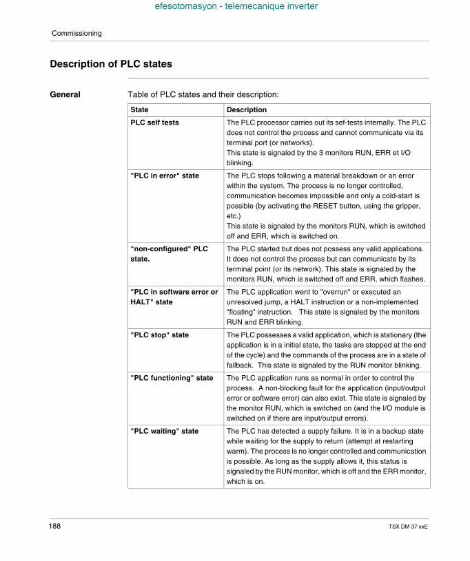
Commissioning
efesotomasyon - telemecanique inverter
Description of PLC states
General Table of PLC states and their description:
State Description
PLC self tests The PLC processor carries out its sef-tests internally. The PLCdoes not control the process and cannot communicate via itsterminal port (or networks).This state is signaled by the 3 monitors RUN, ERR et I/Oblinking.
"PLC in error" state The PLC stops following a material breakdown or an errorwithin the system. The process is no longer controlled,communication becomes impossible and only a cold-start ispossible (by activating the RESET button, using the gripper,etc.)This state is signaled by the monitors RUN, which is switchedoff and ERR, which is switched on.
"non-configured" PLCstate.
The PLC started but does not possess any valid applications.It does not control the process but can communicate by itsterminal point (or its network). This state is signaled by themonitors RUN, which is switched off and ERR, which flashes.
"PLC in software error orHALT" state
The PLC application went to "overrun" or executed anunresolved jump, a HALT instruction or a non-implemented"floating" instruction. This state is signaled by the monitorsRUN and ERR blinking.
"PLC stop" state The PLC possesses a valid application, which is stationary (theapplication is in a initial state, the tasks are stopped at the endof the cycle) and the commands of the process are in a state offallback. This state is signaled by the RUN monitor blinking.
"PLC functioning" state The PLC application runs as normal in order to control theprocess. A non-blocking fault for the application (input/outputerror or software error) can also exist. This state is signaled bythe monitor RUN, which is switched on (and the I/O module isswitched on if there are input/output errors).
"PLC waiting" state The PLC has detected a supply failure. It is in a backup statewhile waiting for the supply to return (attempt at restartingwarm). The process is no longer controlled and communicationis possible. As long as the supply allows it, this status issignaled by the RUN monitor, which is off and the ERR monitor,which is on.
188 TSX DM 37 xxE
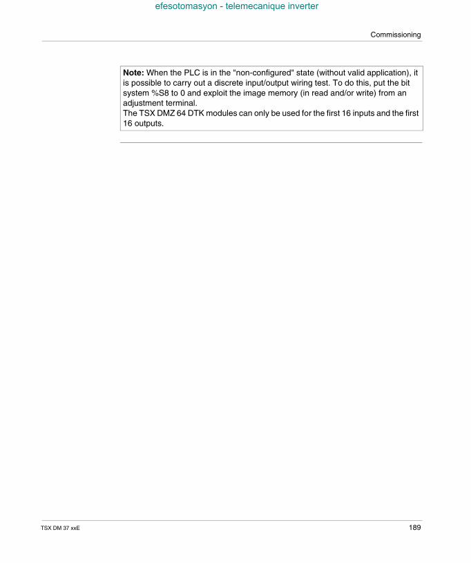
Commissioning
efesotomasyon - telemecanique inverter
Note: When the PLC is in the "non-configured" state (without valid application), itis possible to carry out a discrete input/output wiring test. To do this, put the bitsystem %S8 to 0 and exploit the image memory (in read and/or write) from anadjustment terminal.The TSX DMZ 64 DTK modules can only be used for the first 16 inputs and the first16 outputs.
TSX DM 37 xxE 189

Commissioning
efesotomasyon - telemecanique inverter
190 TSX DM 37 xxE
TSX DM 37 xxE
efesotomasyon - telemecanique inverter
20
MaintenanceAt a Glance
Aim of thisChapter
This chapter is about researching and analyzing the errors.
What's in thisChapter?
This Chapter contains the following Maps:
Topic Page
Researching the errors from PLC status monitors. 192
Non-blocking faults 193
Blocking faults 195
Central processing unit (CPU) faults 197
Updating the Operating System 198
191
Maintenance
efesotomasyon - telemecanique inverter
Researching the errors from PLC status monitors.
General The status monitors in the display block inform the user on the operating mode ofthe PLC but also on its possible faults. The errors detected by the PLC concern: the PLC component circuits and/or its modules: internal errors, the process controlled by the PLC or the process wiring: external errors, the operating of the application carried out by the PLC: internal or external errors.
Errors are detected at start-up (self-tests) or during operation; as is the case with themajority of hardware errors, during the exchanges with the modules or during theexecution of an instruction program. With certain "serious" errors, the PLC must berestarted; others are the responsibility of the user who decides on the course ofaction according to the desired application level.
There are three types of error: non-blocking errors, blocking errors and central unit errors.
192 TSX DM 37 xxE
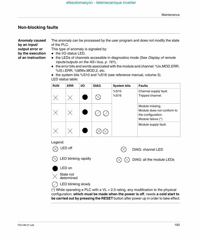
Maintenance
efesotomasyon - telemecanique inverter
Non-blocking faults
Anomaly causedby an input/output error orby the executionof an instruction
The anomaly can be processed by the user program and does not modify the stateof the PLC.This type of anomaly is signaled by: the I/O status LED, the LEDs of channels accessible in diagnostics mode (See Display of remote
inputs/outputs on the AS-i bus, p. 161), the error bits and words associated with the module and channel: %Ix.MOD.ERR,
%IX.i.ERR, %MWx.MOD.2, etc. the system bits %S10 and %S16 (see reference manual, volume 3).LED status table:
Legend:
(*) While operating a PLC with a VL < 2.0 rating, any modification to the physicalconfiguration, which must be made when the power is off, needs a cold start tobe carried out by pressing the RESET button after power up in order to take effect.
RUN ERR I/O DIAG System bits Faults
%S10%S16
Channel supply fault.Tripped channel.
Module missing.Module does not conform tothe configuration.Module failure (*)
Module supply fault.
LED off
LED blinking rapidly
LED blinking slowly
LED on
State notdetermined
DIAG: channel LED
DIAG: all the module LEDs
TSX DM 37 xxE 193
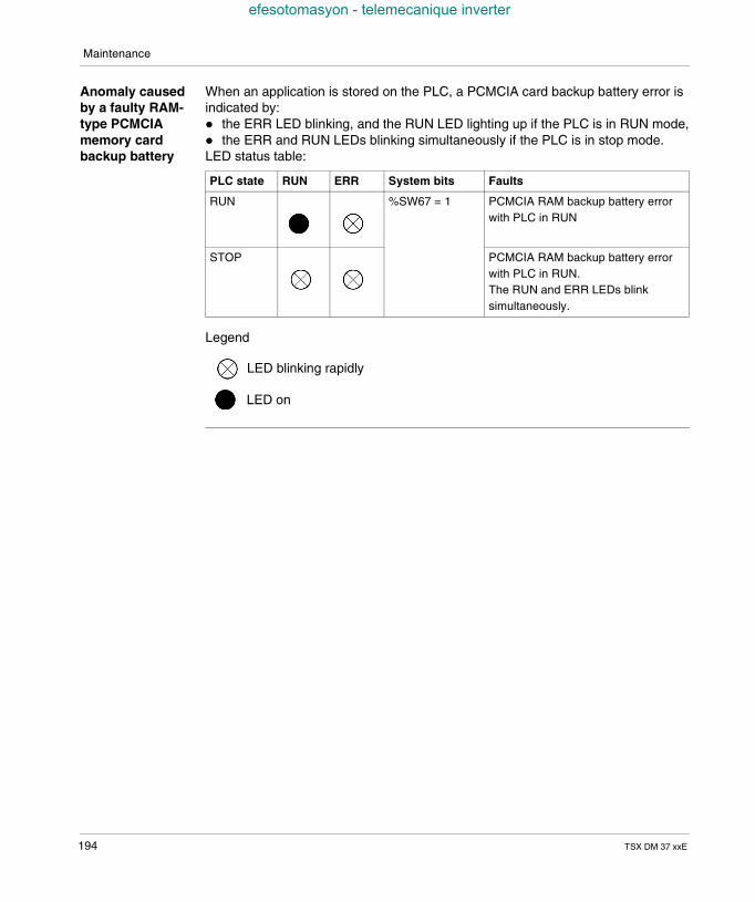
Maintenance
efesotomasyon - telemecanique inverter
Anomaly causedby a faulty RAM-type PCMCIAmemory cardbackup battery
When an application is stored on the PLC, a PCMCIA card backup battery error isindicated by: the ERR LED blinking, and the RUN LED lighting up if the PLC is in RUN mode, the ERR and RUN LEDs blinking simultaneously if the PLC is in stop mode.LED status table:
Legend
PLC state RUN ERR System bits Faults
RUN %SW67 = 1 PCMCIA RAM backup battery errorwith PLC in RUN
STOP PCMCIA RAM backup battery errorwith PLC in RUN.The RUN and ERR LEDs blinksimultaneously.
LED blinking rapidly
LED on
194 TSX DM 37 xxE
Maintenance
efesotomasyon - telemecanique inverter
Blocking faults
General points These faults, caused by the application program, make it impossible to continueexecution but do not lead to a system fault. If such a fault occurs, the applicationstops immediately (all tasks on the current instruction are stopped). There are twopossibilities for restarting the application: with INIT or by setting the %S0 bit to 1. The application is thus in a preliminary
state: the data have their initial values, the tasks are stopped at the end of thecycle, the view of the inputs is refreshed and the outputs are placed into a fallbackposition,
by STOP, which brings the tasks to the end of the cycle without reinitializing thedata, then by RUN, which makes a restart possible.
TSX DM 37 xxE 195
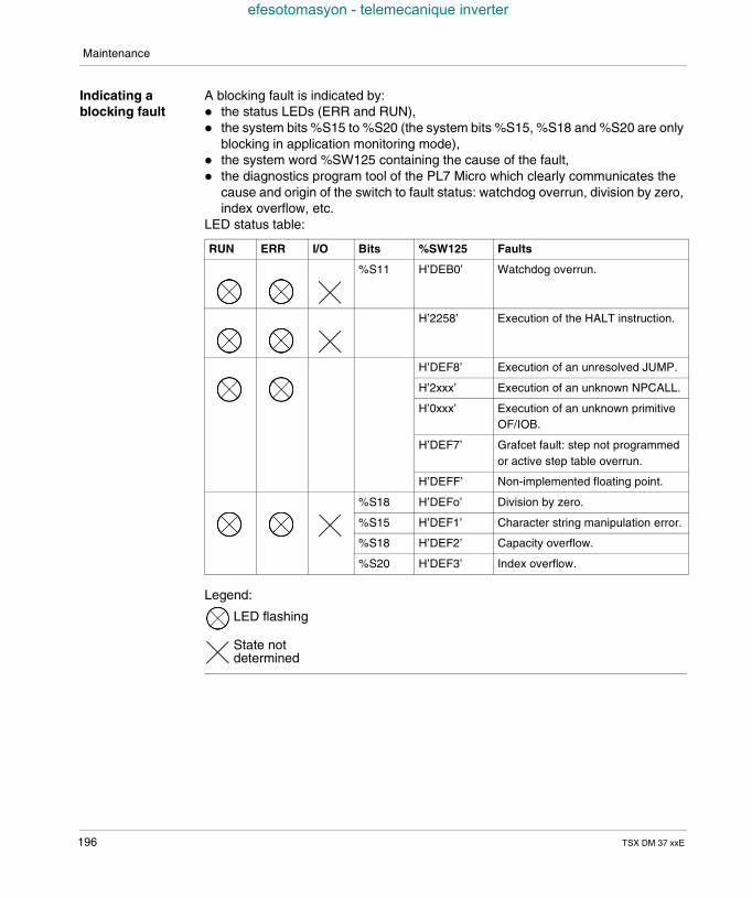
Maintenance
efesotomasyon - telemecanique inverter
Indicating ablocking fault
A blocking fault is indicated by: the status LEDs (ERR and RUN), the system bits %S15 to %S20 (the system bits %S15, %S18 and %S20 are only
blocking in application monitoring mode), the system word %SW125 containing the cause of the fault, the diagnostics program tool of the PL7 Micro which clearly communicates the
cause and origin of the switch to fault status: watchdog overrun, division by zero,index overflow, etc.
LED status table:
Legend:
RUN ERR I/O Bits %SW125 Faults
%S11 H’DEB0’ Watchdog overrun.
H’2258’ Execution of the HALT instruction.
H’DEF8’ Execution of an unresolved JUMP.
H’2xxx’ Execution of an unknown NPCALL.
H’0xxx’ Execution of an unknown primitiveOF/IOB.
H’DEF7’ Grafcet fault: step not programmedor active step table overrun.
H’DEFF’ Non-implemented floating point.
%S18 H’DEFo’ Division by zero.
%S15 H’DEF1’ Character string manipulation error.
%S18 H’DEF2’ Capacity overflow.
%S20 H’DEF3’ Index overflow.
LED flashing
State notdetermined
196 TSX DM 37 xxE
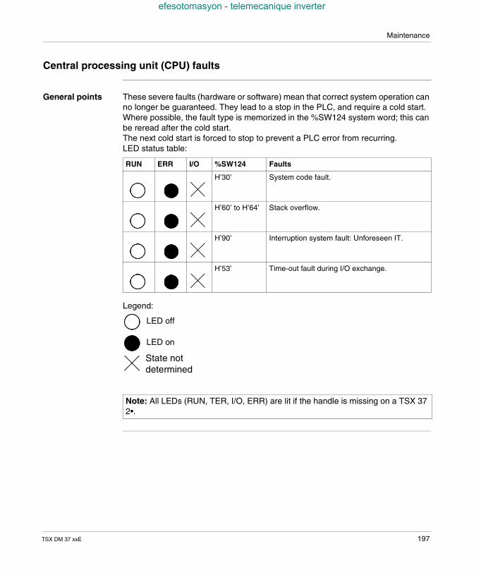
Maintenance
efesotomasyon - telemecanique inverter
Central processing unit (CPU) faults
General points These severe faults (hardware or software) mean that correct system operation canno longer be guaranteed. They lead to a stop in the PLC, and require a cold start.Where possible, the fault type is memorized in the %SW124 system word; this canbe reread after the cold start.The next cold start is forced to stop to prevent a PLC error from recurring.LED status table:
Legend:
RUN ERR I/O %SW124 Faults
H’30’ System code fault.
H’60’ to H’64’ Stack overflow.
H’90’ Interruption system fault: Unforeseen IT.
H’53’ Time-out fault during I/O exchange.
Note: All LEDs (RUN, TER, I/O, ERR) are lit if the handle is missing on a TSX 372•.
LED off
LED on
State notdetermined
TSX DM 37 xxE 197
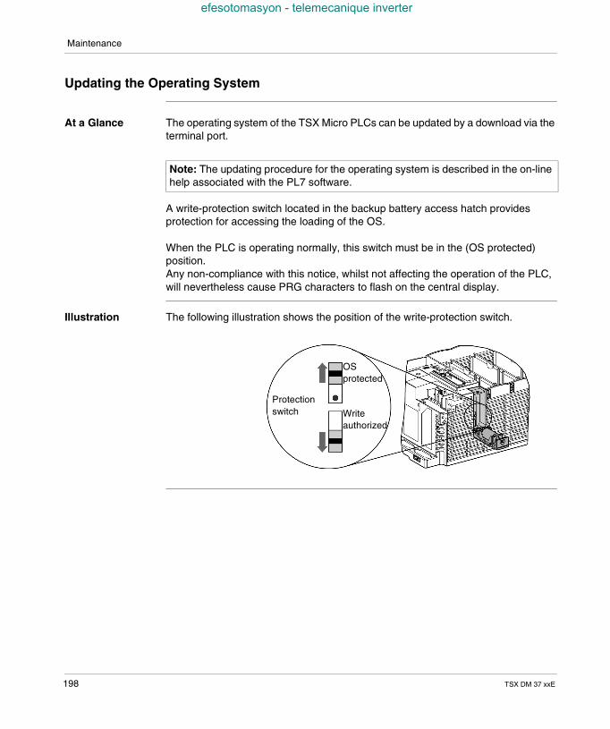
Maintenance
efesotomasyon - telemecanique inverter
Updating the Operating System
At a Glance The operating system of the TSX Micro PLCs can be updated by a download via theterminal port.
A write-protection switch located in the backup battery access hatch providesprotection for accessing the loading of the OS.
When the PLC is operating normally, this switch must be in the (OS protected)position.Any non-compliance with this notice, whilst not affecting the operation of the PLC,will nevertheless cause PRG characters to flash on the central display.
Illustration The following illustration shows the position of the write-protection switch.
Note: The updating procedure for the operating system is described in the on-linehelp associated with the PL7 software.
OSprotected
Protectionswitch Write
authorized
198 TSX DM 37 xxE
Maintenance
efesotomasyon - telemecanique inverter
Updating the OS The tool OS LOADER, provided with PL7, acts as a guide for the user during theupdate phase, indicating in particular that: the write-protection switch must be in the write authorized position in order to be
able to begin downloading the OS, the write-protection switch must be in the OS protected position once the OS has
finished downloading.
Note: If the OS is updated with the tool OS-LOADER V1.5, you must be sure to putthe protection switch in the "write authorized" position before starting the download,as this version of the tool does not guide the user through the entire update phase.Likewise, once loading is complete, the switch must be put in the "OS protected"position.
TSX DM 37 xxE 199

Maintenance
efesotomasyon - telemecanique inverter
200 TSX DM 37 xxE
TSX DM 37 xxE
efesotomasyon - telemecanique inverter
V
Analog incorporated in the basesAt a Glance
Aim of this tab This tab deals with the analog interface which is built into the TSX PLC
What's in thispart?
This Part contains the following Chapters:
Chapter Chaptername Page
21 Overview of the built-in analog interface 203
22 Connecting the built in interface 209
23 TSX ACZ 03 adjustment and adaptation module 219
201

Analog incorporated in the bases
efesotomasyon - telemecanique inverter
202 TSX DM 37 xxE
TSX DM 37 xxE
efesotomasyon - telemecanique inverter
21
Overview of the built-in analoginterfaceAt a Glance
Aim of thischapter
This chapter describes the analog interface built-in to the TSX PLC.
What's in thisChapter?
This Chapter contains the following Maps:
Topic Page
General 204
Functions 205
Characteristics of the built-in analog inputs 207
Built-in analog output feature 208
203
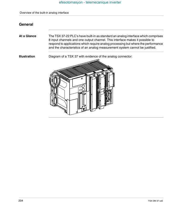
Overview of the built-in analog interface
efesotomasyon - telemecanique inverter
General
At a Glance The TSX 37-22 PLC’s have built-in as standard an analog interface which comprises8 input channels and one output channel. This interface makes it possible torespond to applications which require analog processing but where the performanceand the characteristics of an analog measurement system cannot be justified.
Illustration Diagram of a TSX 37 with evidence of the analog connector:
204 TSX DM 37 xxE
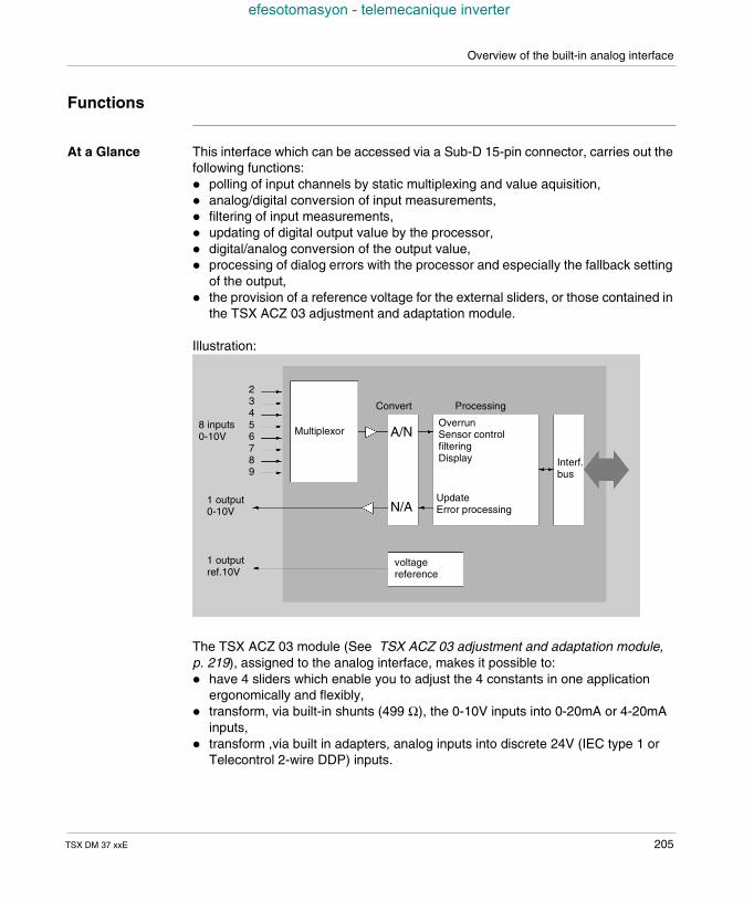
Overview of the built-in analog interface
efesotomasyon - telemecanique inverter
Functions
At a Glance This interface which can be accessed via a Sub-D 15-pin connector, carries out thefollowing functions: polling of input channels by static multiplexing and value aquisition, analog/digital conversion of input measurements, filtering of input measurements, updating of digital output value by the processor, digital/analog conversion of the output value, processing of dialog errors with the processor and especially the fallback setting
of the output, the provision of a reference voltage for the external sliders, or those contained in
the TSX ACZ 03 adjustment and adaptation module.
Illustration:
The TSX ACZ 03 module (See TSX ACZ 03 adjustment and adaptation module,p. 219), assigned to the analog interface, makes it possible to: have 4 sliders which enable you to adjust the 4 constants in one application
ergonomically and flexibly, transform, via built-in shunts (499 Ω), the 0-10V inputs into 0-20mA or 4-20mA
inputs, transform ,via built in adapters, analog inputs into discrete 24V (IEC type 1 or
Telecontrol 2-wire DDP) inputs.
23456789
Multiplexor A/N
N/A
Convert Processing
OverrunSensor controlfilteringDisplay
UpdateError processing
Interf.bus
8 inputs0-10V
1 output0-10V
voltagereference
1 outputref.10V
TSX DM 37 xxE 205
Overview of the built-in analog interface
efesotomasyon - telemecanique inverter
Using the TELEFAST pre-cabling system (ABE-7CPA01) (See Using theTELEFAST pre-wiring system, p. 211), whether or not it is assigned to the TSX ACZ03 module, makes input/output connection easier by providing screw terminalblocks. It also makes connecting PLC discrete inputs/outputs easier if the analogoutput is used to control a variable controller.
206 TSX DM 37 xxE
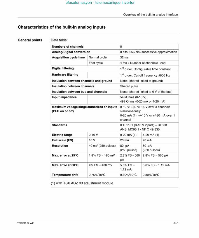
Overview of the built-in analog interface
efesotomasyon - telemecanique inverter
Characteristics of the built-in analog inputs
General points Data table:
(1) with TSX ACZ 03 adjustment module.
Numbers of channels 8
Analog/Digital conversion 8 bits (256 pin) successive approximation
Acquisition cycle time Normal cycle 32 ms
Fast cycle 4 ms x Number of channels used
Digital filtering 1st order. Configurable time constant
Hardware filtering 1st order. Cut-off frequency #600 Hz
Insulation between channels and ground None (shared linked to ground)
Insulation between channels Shared pulse
Insulation between bus and channels None (shared linked to 0 V of the bus)
Input impedance 54 kOhms (0-10 V)499 Ohms (0-20 mA or 4-20 mA)
Maximum voltage surge authorized on inputs(PLC on or off)
0-10 V: +30 V/-15 V over 3 channelssimultaneously0-20 mA (1): +/-15 V or +/-30 mA over 1channel
Standards IEC 1131 (0-10 V inputs) – UL508ANSI MC96.1 - NF C 42-330
Electric range 0-10 V 0-20 mA (1) 4-20 mA (1)
Full scale (FS) 10 V 20 mA 20 mA
Resolution 40 mV (250 pulses) 80 µA(250 pulses)
80 µA(250 pulses)
Max. error at 25°C 1.8% FS = 180 mV 2.8% FS = 560µA
2.8% FS = 560 µA
Max. error at 60°C 4% FS = 400 mV 5.6% FS =1.12 mA
5.6% FS = 1.12 mA
Temperature drift 0.75%/10°C 0.80%/10°C 0.80%/10°C
TSX DM 37 xxE 207
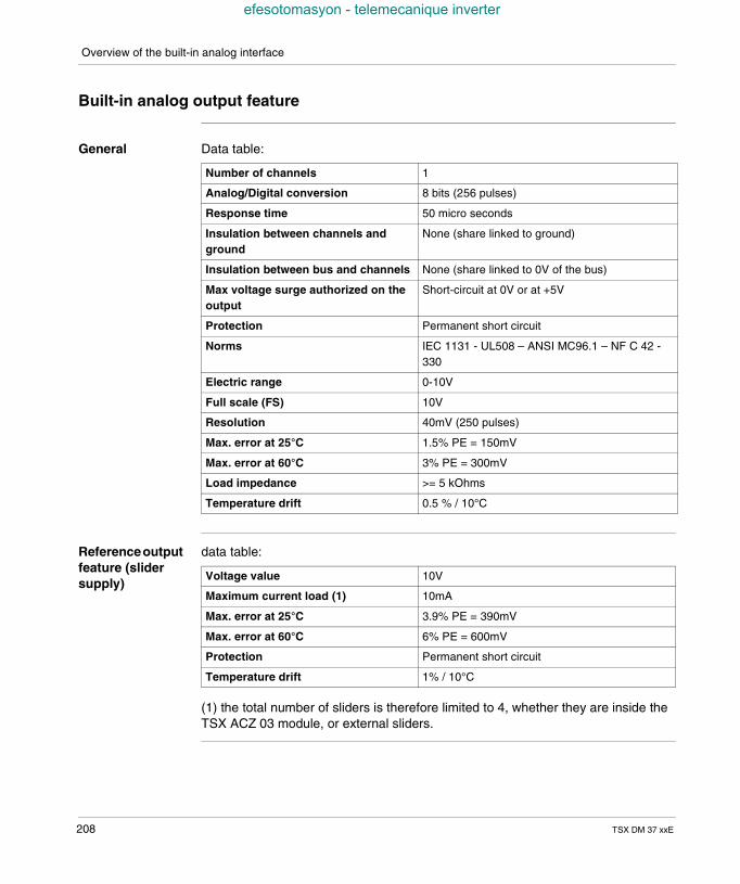
Overview of the built-in analog interface
efesotomasyon - telemecanique inverter
Built-in analog output feature
General Data table:
Referenceoutputfeature (slidersupply)
data table:
(1) the total number of sliders is therefore limited to 4, whether they are inside theTSX ACZ 03 module, or external sliders.
Number of channels 1
Analog/Digital conversion 8 bits (256 pulses)
Response time 50 micro seconds
Insulation between channels andground
None (share linked to ground)
Insulation between bus and channels None (share linked to 0V of the bus)
Max voltage surge authorized on theoutput
Short-circuit at 0V or at +5V
Protection Permanent short circuit
Norms IEC 1131 - UL508 – ANSI MC96.1 – NF C 42 -330
Electric range 0-10V
Full scale (FS) 10V
Resolution 40mV (250 pulses)
Max. error at 25°C 1.5% PE = 150mV
Max. error at 60°C 3% PE = 300mV
Load impedance >= 5 kOhms
Temperature drift 0.5 % / 10°C
Voltage value 10V
Maximum current load (1) 10mA
Max. error at 25°C 3.9% PE = 390mV
Max. error at 60°C 6% PE = 600mV
Protection Permanent short circuit
Temperature drift 1% / 10°C
208 TSX DM 37 xxE
TSX DM 37 xxE
efesotomasyon - telemecanique inverter
22
Connecting the built in interfaceAt a Glance
Aim of thischapter
This chapter deals with connecting the built in analog interface.
What's in thisChapter?
This Chapter contains the following Maps:
Topic Page
Direct connection of the analog interface 210
Using the TELEFAST pre-wiring system 211
Connecting analog inputs with insulated or non-insulated sensors 213
Connecting analog output and external sliders 214
Connecting a variable speed controller 215
Details of wiring the ALTIVAR 16 216
ABE-7CPA01 analog TELEFAST internal wiring 218
209
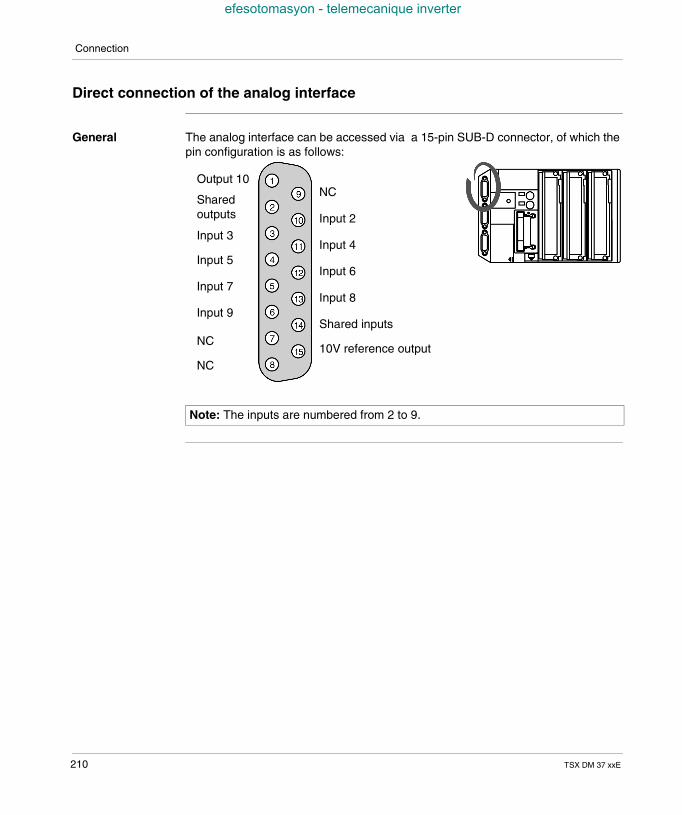
Connection
efesotomasyon - telemecanique inverter
Direct connection of the analog interface
General The analog interface can be accessed via a 15-pin SUB-D connector, of which thepin configuration is as follows:
Note: The inputs are numbered from 2 to 9.
NC
Input 2
Input 4
Input 6
Input 8
Shared inputs
10V reference output
Output 10
Sharedoutputs
Input 3
Input 5
Input 7
Input 9
NC
NC
210 TSX DM 37 xxE
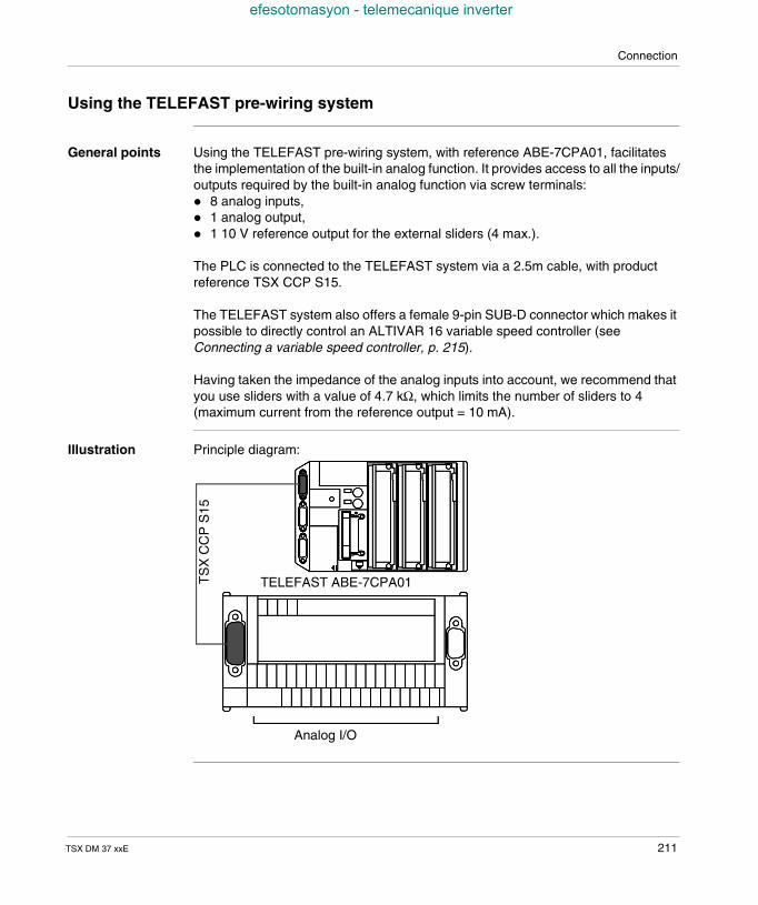
Connection
efesotomasyon - telemecanique inverter
Using the TELEFAST pre-wiring system
General points Using the TELEFAST pre-wiring system, with reference ABE-7CPA01, facilitatesthe implementation of the built-in analog function. It provides access to all the inputs/outputs required by the built-in analog function via screw terminals: 8 analog inputs, 1 analog output, 1 10 V reference output for the external sliders (4 max.).
The PLC is connected to the TELEFAST system via a 2.5m cable, with productreference TSX CCP S15.
The TELEFAST system also offers a female 9-pin SUB-D connector which makes itpossible to directly control an ALTIVAR 16 variable speed controller (seeConnecting a variable speed controller, p. 215).
Having taken the impedance of the analog inputs into account, we recommend thatyou use sliders with a value of 4.7 kΩ, which limits the number of sliders to 4(maximum current from the reference output = 10 mA).
Illustration Principle diagram:
TELEFAST ABE-7CPA01TS
XC
CP
S15
Analog I/O
TSX DM 37 xxE 211
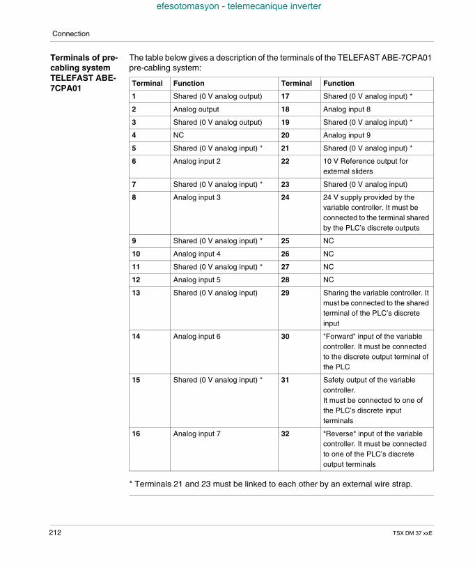
Connection
efesotomasyon - telemecanique inverter
Terminals of pre-cabling systemTELEFAST ABE-7CPA01
The table below gives a description of the terminals of the TELEFAST ABE-7CPA01pre-cabling system:
* Terminals 21 and 23 must be linked to each other by an external wire strap.
Terminal Function Terminal Function
1 Shared (0 V analog output) 17 Shared (0 V analog input) *
2 Analog output 18 Analog input 8
3 Shared (0 V analog output) 19 Shared (0 V analog input) *
4 NC 20 Analog input 9
5 Shared (0 V analog input) * 21 Shared (0 V analog input) *
6 Analog input 2 22 10 V Reference output forexternal sliders
7 Shared (0 V analog input) * 23 Shared (0 V analog input)
8 Analog input 3 24 24 V supply provided by thevariable controller. It must beconnected to the terminal sharedby the PLC’s discrete outputs
9 Shared (0 V analog input) * 25 NC
10 Analog input 4 26 NC
11 Shared (0 V analog input) * 27 NC
12 Analog input 5 28 NC
13 Shared (0 V analog input) 29 Sharing the variable controller. Itmust be connected to the sharedterminal of the PLC’s discreteinput
14 Analog input 6 30 "Forward" input of the variablecontroller. It must be connectedto the discrete output terminal ofthe PLC
15 Shared (0 V analog input) * 31 Safety output of the variablecontroller.It must be connected to one ofthe PLC’s discrete inputterminals
16 Analog input 7 32 "Reverse" input of the variablecontroller. It must be connectedto one of the PLC’s discreteoutput terminals
212 TSX DM 37 xxE
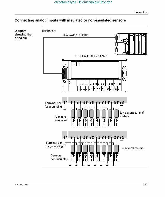
Connection
efesotomasyon - telemecanique inverter
Connecting analog inputs with insulated or non-insulated sensors
Diagramshowing theprinciple
Illustration:
TELEFAST ABE-7CPA01
Terminal barfor grounding
Sensorsinsulated
Terminal barfor grounding
Sensorsnon-insulated
L = several meters
L = several tens ofmeters
TSX CCP 515 cable
TSX DM 37 xxE 213
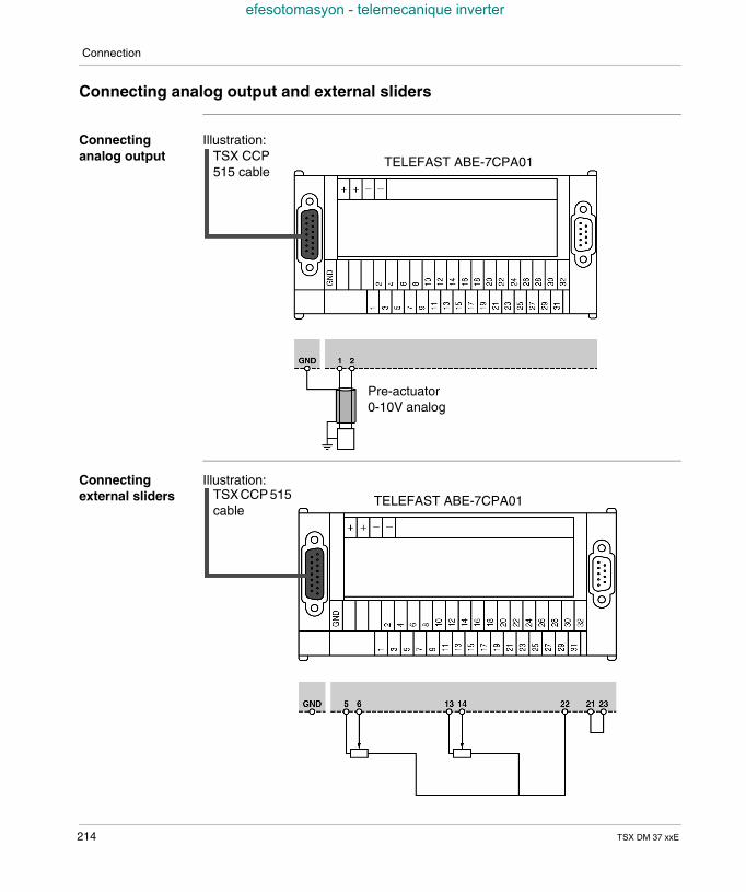
Connection
efesotomasyon - telemecanique inverter
Connecting analog output and external sliders
Connectinganalog output
Illustration:
Connectingexternal sliders
Illustration:
TELEFAST ABE-7CPA01
Pre-actuator0-10V analog
TSX CCP515 cable
TSXCCP 515cable
TELEFAST ABE-7CPA01
214 TSX DM 37 xxE
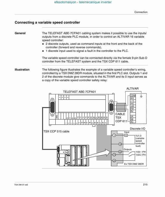
Connection
efesotomasyon - telemecanique inverter
Connecting a variable speed controller
General The TELEFAST ABE-7CPA01 cabling system makes it possible to use the inputs/outputs from a discrete PLC module, in order to control an ALTIVAR 16 variablespeed controller: 2 discrete outputs, used as command inputs at the front and the back of the
controller (forward and reverse commands), 1 discrete input used to signal a fault in the controller to the PLC.
The variable speed controller can be connected directly via the female 9-pin Sub-Dcontroller from the TELEFAST system and the TSX CDP 611 cable.
Illustration The following figure illustrates the example of a variable speed controller’s wiring,controlled by a TSX DMZ 28DR module, situated in the first PLC slot. Outputs 1 and2 of the discrete module give commands to the ALTIVAR and its 0 input serves asa copy of the variable speed controller safety relay:
TELEFAST ABE-7CPA01ALTIVAR
CABLETSXCDP 611
Discrete I/O
%I1.0(variablespeedcontrollerfault)
Input
Ex TSX DMZ 28DR
Outputs
TSX CCP 515 cable
TSX DM 37 xxE 215
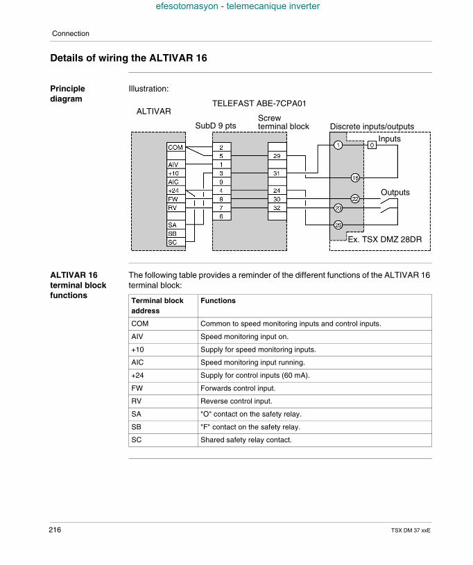
Connection
efesotomasyon - telemecanique inverter
Details of wiring the ALTIVAR 16
Principlediagram
Illustration:
ALTIVAR 16terminal blockfunctions
The following table provides a reminder of the different functions of the ALTIVAR 16terminal block:
ALTIVARTELEFAST ABE-7CPA01
Discrete inputs/outputs
Ex. TSX DMZ 28DR
SubD 9 ptsScrewterminal block
Inputs
Outputs
Terminal blockaddress
Functions
COM Common to speed monitoring inputs and control inputs.
AIV Speed monitoring input on.
+10 Supply for speed monitoring inputs.
AIC Speed monitoring input running.
+24 Supply for control inputs (60 mA).
FW Forwards control input.
RV Reverse control input.
SA "O" contact on the safety relay.
SB "F" contact on the safety relay.
SC Shared safety relay contact.
216 TSX DM 37 xxE
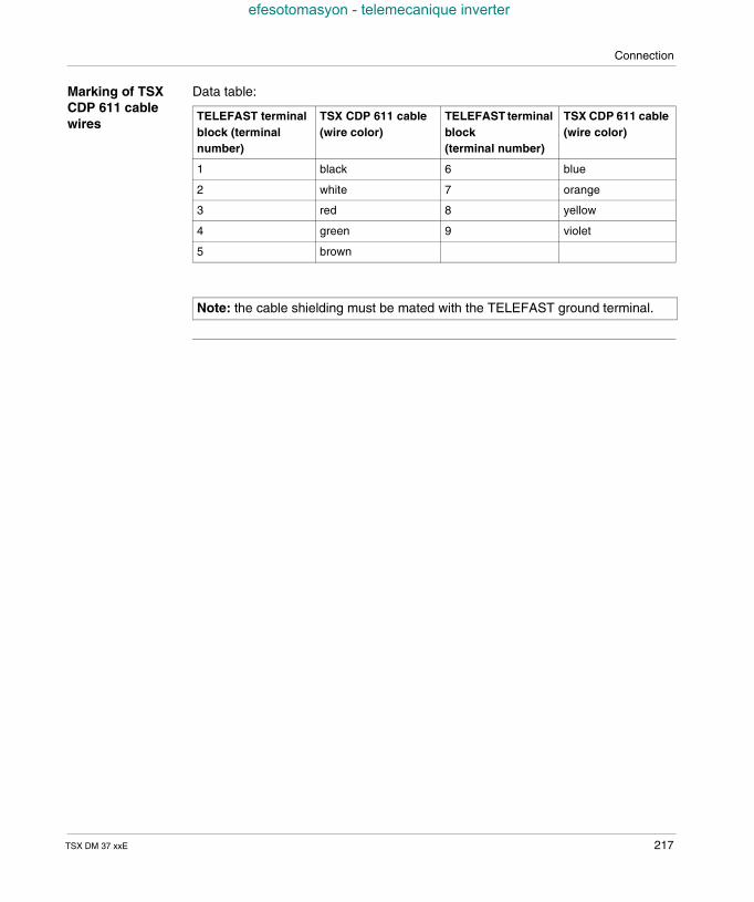
Connection
efesotomasyon - telemecanique inverter
Marking of TSXCDP 611 cablewires
Data table:
TELEFAST terminalblock (terminalnumber)
TSX CDP 611 cable(wire color)
TELEFAST terminalblock(terminal number)
TSX CDP 611 cable(wire color)
1 black 6 blue
2 white 7 orange
3 red 8 yellow
4 green 9 violet
5 brown
Note: the cable shielding must be mated with the TELEFAST ground terminal.
TSX DM 37 xxE 217
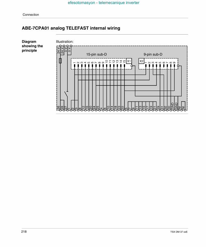
Connection
efesotomasyon - telemecanique inverter
ABE-7CPA01 analog TELEFAST internal wiring
Diagramshowing theprinciple
Illustration:
15-pin sub-D 9-pin sub-D
218 TSX DM 37 xxE
TSX DM 37 xxE
efesotomasyon - telemecanique inverter
23
TSX ACZ 03 adjustment andadaptation module
At a Glance
Aim of thischapter
This chapter deals with the TSX ACZ 03 module and its implementation.
What's in thisChapter?
This Chapter contains the following Maps:
Topic Page
TSX ACZ 03 adjustment and adaptation module: at a glance 220
Module standard functions 222
Module implementation 224
Selecting the function carried out by the module 227
219
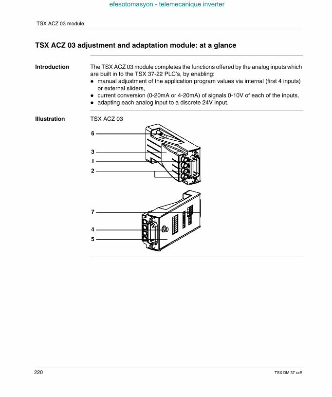
TSX ACZ 03 module
efesotomasyon - telemecanique inverter
TSX ACZ 03 adjustment and adaptation module: at a glance
Introduction The TSX ACZ 03 module completes the functions offered by the analog inputs whichare built in to the TSX 37-22 PLC’s, by enabling: manual adjustment of the application program values via internal (first 4 inputs)
or external sliders, current conversion (0-20mA or 4-20mA) of signals 0-10V of each of the inputs, adapting each analog input to a discrete 24V input.
Illustration TSX ACZ 03
220 TSX DM 37 xxE
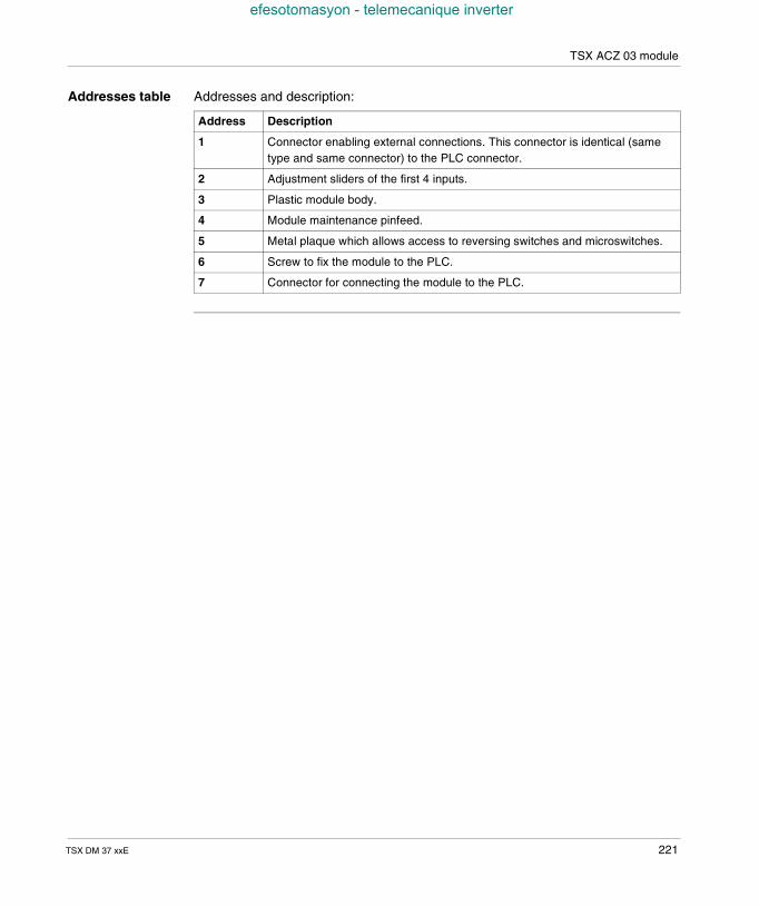
TSX ACZ 03 module
efesotomasyon - telemecanique inverter
Addresses table Addresses and description:
Address Description
1 Connector enabling external connections. This connector is identical (sametype and same connector) to the PLC connector.
2 Adjustment sliders of the first 4 inputs.
3 Plastic module body.
4 Module maintenance pinfeed.
5 Metal plaque which allows access to reversing switches and microswitches.
6 Screw to fix the module to the PLC.
7 Connector for connecting the module to the PLC.
TSX DM 37 xxE 221
TSX ACZ 03 module
efesotomasyon - telemecanique inverter
Module standard functions
Introduction For each of these inputs, the standard functions offered by the TSX ACZ 03 moduleare as follows:
1 Transfer ofanalog input tothe moduleconnector
The 0-10V analog inputs (See Characteristics of the built-in analog inputs, p. 207),the output and the reference voltage, available on the PLC connector, aretransferred to the connector on the front of the TSX ACZ 03 module, with the sameconnector (see Direct connection of the analog interface, p. 210).
2 Input signaladjustments
The input signal (setpoint, threshold, timer, etc.) is chosen by using an internal sliderfor the first 4 inputs, and an external one for the other inputs (transfer of unusedchannels onto the upper connector).A reference output (See Reference output feature (slider supply), p. 208) is suppliedby the PLC to supply the internal sliders (for a maximum of 4 inputs).
3 Conversion ofthe input in the 0-20 mA or 4-20 mArange.
A powered channel is chosen (See Characteristics of the built-in analog inputs,p. 207) by positioning a microswitch on the module, after adaptation has beencarried out by joining on a 499 Ω 1% resistor.A current range is chosen from the 2 possible options (0-20 mA or 4-20 mA) whenthe software is configured.
222 TSX DM 37 xxE
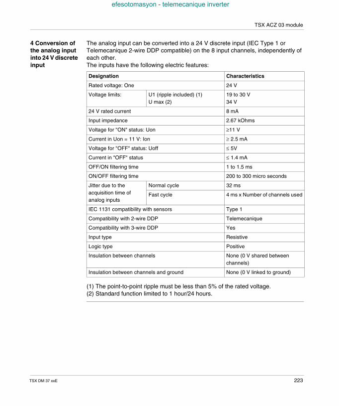
TSX ACZ 03 module
efesotomasyon - telemecanique inverter
4 Conversion ofthe analog inputinto 24 V discreteinput
The analog input can be converted into a 24 V discrete input (IEC Type 1 orTelemecanique 2-wire DDP compatible) on the 8 input channels, independently ofeach other.The inputs have the following electric features:
(1) The point-to-point ripple must be less than 5% of the rated voltage.(2) Standard function limited to 1 hour/24 hours.
Designation Characteristics
Rated voltage: One 24 V
Voltage limits: U1 (ripple included) (1)U max (2)
19 to 30 V34 V
24 V rated current 8 mA
Input impedance 2.67 kOhms
Voltage for "ON" status: Uon ≥11 V
Current in Uon = 11 V: Ion ≥ 2.5 mA
Voltage for "OFF" status: Uoff ≤ 5V
Current in "OFF" status ≤ 1.4 mA
OFF/ON filtering time 1 to 1.5 ms
ON/OFF filtering time 200 to 300 micro seconds
Jitter due to theacquisition time ofanalog inputs
Normal cycle 32 ms
Fast cycle 4 ms x Number of channels used
IEC 1131 compatibility with sensors Type 1
Compatibility with 2-wire DDP Telemecanique
Compatibility with 3-wire DDP Yes
Input type Resistive
Logic type Positive
Insulation between channels None (0 V shared betweenchannels)
Insulation between channels and ground None (0 V linked to ground)
TSX DM 37 xxE 223
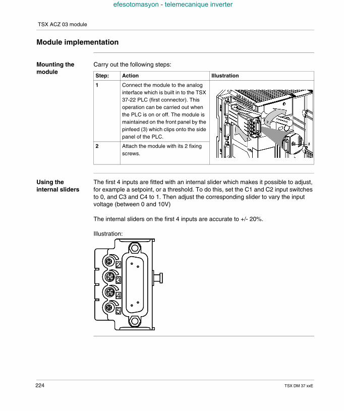
TSX ACZ 03 module
efesotomasyon - telemecanique inverter
Module implementation
Mounting themodule
Carry out the following steps:
Using theinternal sliders
The first 4 inputs are fitted with an internal slider which makes it possible to adjust,for example a setpoint, or a threshold. To do this, set the C1 and C2 input switchesto 0, and C3 and C4 to 1. Then adjust the corresponding slider to vary the inputvoltage (between 0 and 10V)
The internal sliders on the first 4 inputs are accurate to +/- 20%.
Illustration:
Step: Action Illustration
1 Connect the module to the analoginterface which is built in to the TSX37-22 PLC (first connector). Thisoperation can be carried out whenthe PLC is on or off. The module ismaintained on the front panel by thepinfeed (3) which clips onto the sidepanel of the PLC.
2 Attach the module with its 2 fixingscrews.
224 TSX DM 37 xxE
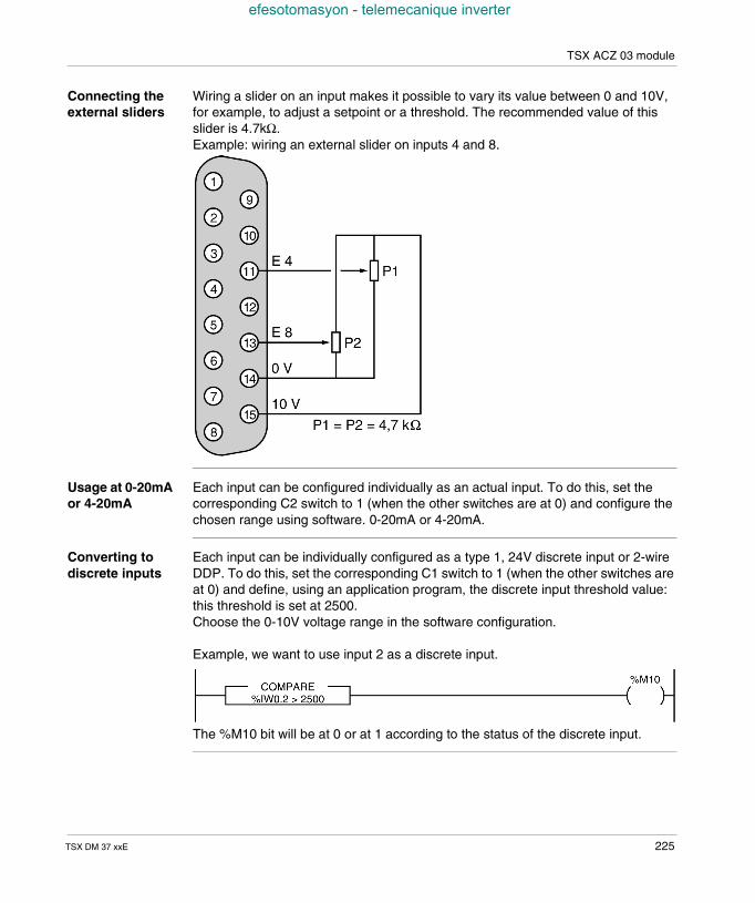
TSX ACZ 03 module
efesotomasyon - telemecanique inverter
Connecting theexternal sliders
Wiring a slider on an input makes it possible to vary its value between 0 and 10V,for example, to adjust a setpoint or a threshold. The recommended value of thisslider is 4.7kΩ.Example: wiring an external slider on inputs 4 and 8.
Usage at 0-20mAor 4-20mA
Each input can be configured individually as an actual input. To do this, set thecorresponding C2 switch to 1 (when the other switches are at 0) and configure thechosen range using software. 0-20mA or 4-20mA.
Converting todiscrete inputs
Each input can be individually configured as a type 1, 24V discrete input or 2-wireDDP. To do this, set the corresponding C1 switch to 1 (when the other switches areat 0) and define, using an application program, the discrete input threshold value:this threshold is set at 2500.Choose the 0-10V voltage range in the software configuration.
Example, we want to use input 2 as a discrete input.
The %M10 bit will be at 0 or at 1 according to the status of the discrete input.
TSX DM 37 xxE 225
TSX ACZ 03 module
efesotomasyon - telemecanique inverter
Connecting theexternal sensorsand pre-actuators
It is carried out via the 15-pin Sub-D connector available on the module, of which thepin configuration is identical to that of the analog interface connector which is builtin to the PLC.
226 TSX DM 37 xxE
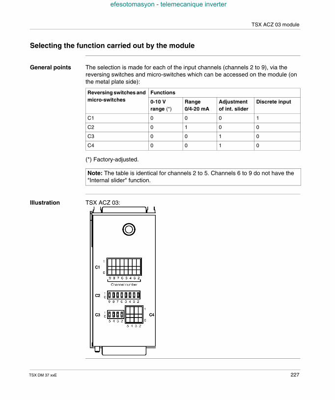
TSX ACZ 03 module
efesotomasyon - telemecanique inverter
Selecting the function carried out by the module
General points The selection is made for each of the input channels (channels 2 to 9), via thereversing switches and micro-switches which can be accessed on the module (onthe metal plate side):
(*) Factory-adjusted.
Illustration TSX ACZ 03:
Reversing switches andmicro-switches
Functions
0-10 Vrange (*)
Range0/4-20 mA
Adjustmentof int. slider
Discrete input
C1 0 0 0 1
C2 0 1 0 0
C3 0 0 1 0
C4 0 0 1 0
Note: The table is identical for channels 2 to 5. Channels 6 to 9 do not have the"Internal slider" function.
TSX DM 37 xxE 227

TSX ACZ 03 module
efesotomasyon - telemecanique inverter
228 TSX DM 37 xxE
TSX DM 37 xxE
efesotomasyon - telemecanique inverter
VI
Counting built into basesAt a Glance
Aim of this tab This tab deals with the built-in counting function on TSX Micro.
What's in thispart?
This Part contains the following Chapters:
Chapter Chaptername Page
24 Overview of built-in counting function 231
25 Overview of different counting functions 235
26 Counting functions on (500Hz) discrete inputs 239
27 Up counting functions built in to (10KHz) TSX 37 22 bases 247
28 Implementing 500Hz up counting on discrete inputs 259
29 Implementing 10KHz upcounter onto TSX 37-22 bases 271
30 Appendices 291
229

Counting built into bases
efesotomasyon - telemecanique inverter
230 TSX DM 37 xxE
TSX DM 37 xxE
efesotomasyon - telemecanique inverter
24
Overview of built-in countingfunctionAt a Glance
Aim of thischapter
This chapter describes the built-in counting function on the TSX Micro.
What's in thisChapter?
This Chapter contains the following Maps:
Topic Page
500Hz counts on the discrete inputs of TSX 37 bases 232
Built in 10 KHZ counting function on TSX 37 22 bases 233
231
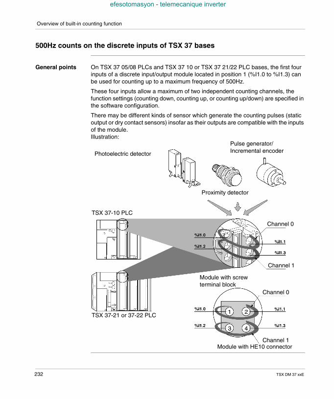
Overview of built-in counting function
efesotomasyon - telemecanique inverter
500Hz counts on the discrete inputs of TSX 37 bases
General points On TSX 37 05/08 PLCs and TSX 37 10 or TSX 37 21/22 PLC bases, the first fourinputs of a discrete input/output module located in position 1 (%I1.0 to %I1.3) canbe used for counting up to a maximum frequency of 500Hz.
These four inputs allow a maximum of two independent counting channels, thefunction settings (counting down, counting up, or counting up/down) are specified inthe software configuration.
There may be different kinds of sensor which generate the counting pulses (staticoutput or dry contact sensors) insofar as their outputs are compatible with the inputsof the module.Illustration:
TSX 37-10 PLC
TSX 37-21 or 37-22 PLC
Module with HE10 connector
Module with screwterminal block
Photoelectric detector
Proximity detector
Pulse generator/Incremental encoder
Channel 0
Channel 0
Channel 1
Channel 1
232 TSX DM 37 xxE
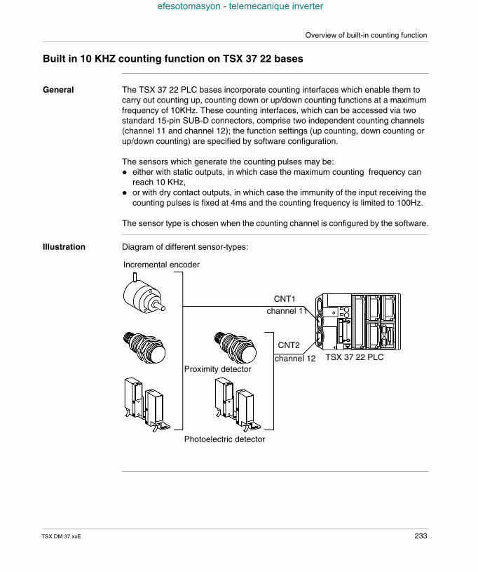
Overview of built-in counting function
efesotomasyon - telemecanique inverter
Built in 10 KHZ counting function on TSX 37 22 bases
General The TSX 37 22 PLC bases incorporate counting interfaces which enable them tocarry out counting up, counting down or up/down counting functions at a maximumfrequency of 10KHz. These counting interfaces, which can be accessed via twostandard 15-pin SUB-D connectors, comprise two independent counting channels(channel 11 and channel 12); the function settings (up counting, down counting orup/down counting) are specified by software configuration.
The sensors which generate the counting pulses may be: either with static outputs, in which case the maximum counting frequency can
reach 10 KHz, or with dry contact outputs, in which case the immunity of the input receiving the
counting pulses is fixed at 4ms and the counting frequency is limited to 100Hz.
The sensor type is chosen when the counting channel is configured by the software.
Illustration Diagram of different sensor-types:
Incremental encoder
CNT1channel 11
CNT2
channel 12Proximity detector
Photoelectric detector
TSX 37 22 PLC
TSX DM 37 xxE 233

Overview of built-in counting function
efesotomasyon - telemecanique inverter
234 TSX DM 37 xxE
TSX DM 37 xxE
efesotomasyon - telemecanique inverter
25
Overview of different countingfunctionsAt a Glance
Aim of thischapter
This chapter describes the different counting functions: counting down function, counting up function, up/down counting function.
What's in thisChapter?
This Chapter contains the following Maps:
Topic Page
Down counting function 236
Up counting function 237
Up/down counting function 238
235
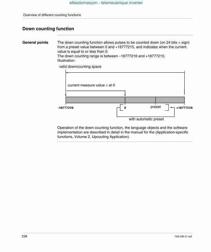
Overview of different counting functions
efesotomasyon - telemecanique inverter
Down counting function
General points The down counting function allows pulses to be counted down (on 24 bits + sign)from a preset value between 0 and +16777215, and indicates when the currentvalue is equal to or less than 0.The down counting range is between –16777216 and +16777215.Illustration:
Operation of the down counting function, the language objects and the softwareimplementation are described in detail in the manual for the (Application-specificfunctions, Volume 2, Upcouting Application).
valid downcounting space
current measure value ≤ at 0
preset
with automatic preset
236 TSX DM 37 xxE
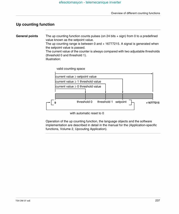
Overview of different counting functions
efesotomasyon - telemecanique inverter
Up counting function
General points The up counting function counts pulses (on 24 bits + sign) from 0 to a predefinedvalue known as the setpoint value.The up counting range is between 0 and + 16777215. A signal is generated whenthe setpoint value is passed.The current value of the counter is always compared with two adjustable thresholds(threshold 0 and threshold 1).Illustration:
Operation of the up counting function, the language objects and the softwareimplementation are described in detail in the manual for the (Application-specificfunctions, Volume 2, Upcouting Application).
valid counting space
current value ≥ setpoint value
current value ≥ 1 threshold value
current value ≥ 0 threshold value
threshold 0 threshold 1 setpoint
with automatic reset to 0
TSX DM 37 xxE 237
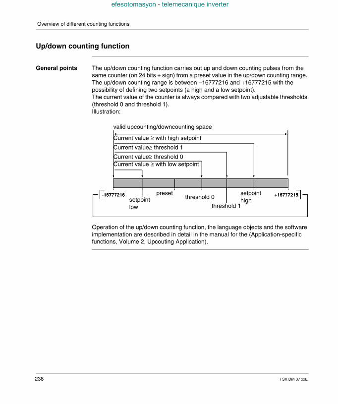
Overview of different counting functions
efesotomasyon - telemecanique inverter
Up/down counting function
General points The up/down counting function carries out up and down counting pulses from thesame counter (on 24 bits + sign) from a preset value in the up/down counting range.The up/down counting range is between –16777216 and +16777215 with thepossibility of defining two setpoints (a high and a low setpoint).The current value of the counter is always compared with two adjustable thresholds(threshold 0 and threshold 1).Illustration:
Operation of the up/down counting function, the language objects and the softwareimplementation are described in detail in the manual for the (Application-specificfunctions, Volume 2, Upcouting Application).
valid upcounting/downcounting space
Current value ≥ with high setpoint
Current value≥ threshold 1
Current value≥ threshold 0Current value ≥ with low setpoint
setpointlow
presetthreshold 0
threshold 1
setpointhigh
238 TSX DM 37 xxE
TSX DM 37 xxE
efesotomasyon - telemecanique inverter
26
Counting functions on (500Hz)discrete inputsAt a Glance
Aim of thischapter
This chapter describes the counting functions on (500Hz) discrete inputs.
What's in thisChapter?
This Chapter contains the following Maps:
Topic Page
Introduction 240
Up counting or down counting 241
Up/down counting 243
239
Counting functions on (500Hz) discrete inputs
efesotomasyon - telemecanique inverter
Introduction
General The four discrete inputs (%I1.0 to %I1.3) of the module located in position 1 allow 2independent up counting, down counting or up/down counting (channel 0 andchannel 1) channels to be made with a maximum frequency of 500Hz.
240 TSX DM 37 xxE
Counting functions on (500Hz) discrete inputs
efesotomasyon - telemecanique inverter
Up counting or down counting
General points The up or down counting pulses are received on the inputIA (%I1.0 for channel 0and %I1.2 for channel 1).
The inputIPres (%I1.1 for channel 0 and %I1.3 for channel 1) can be used: either for setting the preset value of the current value for a down counting
function, or for setting the current value to 0 for an up counting function.
Note:symbol used in PL7-Micro screens for IPres input: IPres if it is a down counting function, IReset if it is an up counting function.
Setting to 0 (up counting) or setting the preset value (down counting) can be carriedout according to one of the methods described below: when the status of the IPres input is changed (rising or falling edge, choice made
in configuration) and when this is validated in the software, automatically as soon as:
the setpoint value has been reached in up counting, the value 0 has been reached in down counting.
(choice made during configuration) via software.
TSX DM 37 xxE 241
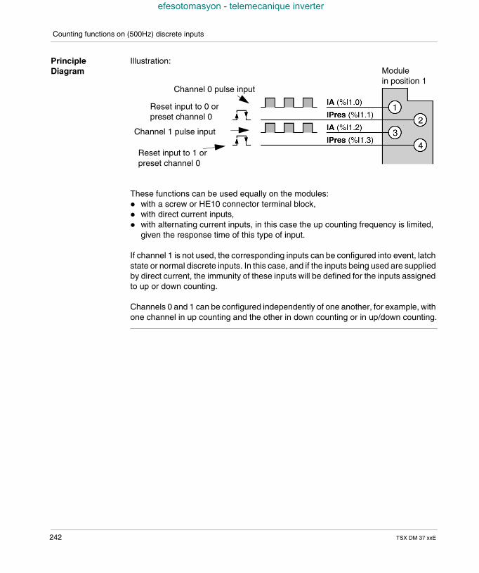
Counting functions on (500Hz) discrete inputs
efesotomasyon - telemecanique inverter
PrincipleDiagram
Illustration:
These functions can be used equally on the modules: with a screw or HE10 connector terminal block, with direct current inputs, with alternating current inputs, in this case the up counting frequency is limited,
given the response time of this type of input.
If channel 1 is not used, the corresponding inputs can be configured into event, latchstate or normal discrete inputs. In this case, and if the inputs being used are suppliedby direct current, the immunity of these inputs will be defined for the inputs assignedto up or down counting.
Channels 0 and 1 can be configured independently of one another, for example, withone channel in up counting and the other in down counting or in up/down counting.
Reset input to 0 orpreset channel 0
Channel 1 pulse input
Modulein position 1
Reset input to 1 orpreset channel 0
Channel 0 pulse input
242 TSX DM 37 xxE
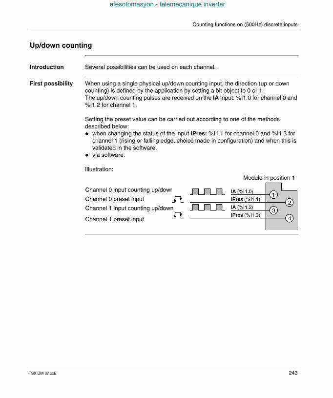
Counting functions on (500Hz) discrete inputs
efesotomasyon - telemecanique inverter
Up/down counting
Introduction Several possibilities can be used on each channel.
First possibility When using a single physical up/down counting input, the direction (up or downcounting) is defined by the application by setting a bit object to 0 or 1.The up/down counting pulses are received on the IA input: %I1.0 for channel 0 and%I1.2 for channel 1.
Setting the preset value can be carried out according to one of the methodsdescribed below: when changing the status of the input IPres: %I1.1 for channel 0 and %I1.3 for
channel 1 (rising or falling edge, choice made in configuration) and when this isvalidated in the software,
via software.
Illustration:
Channel 0 preset input
Module in position 1
Channel 0 input counting up/down
Channel 1 preset input
Channel 1 input counting up/down
TSX DM 37 xxE 243
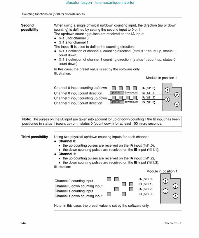
Counting functions on (500Hz) discrete inputs
efesotomasyon - telemecanique inverter
Secondpossibility
When using a single physical up/down counting input, the direction (up or downcounting) is defined by setting the second input to 0 or 1.The up/down counting pulses are received on the IA input: %I1.0 for channel 0, %I1.2 for channel 1.The input IB is used to define the counting direction: %I1.1 definition of channel 0 counting direction: (status 1: count up, status 0:
count down), %I1.3 definition of channel 1 counting direction: (status 1: count up, status 0:
count down).
In this case, the preset value is set by the software only.Illustration:
Third possibility Using two physical up/down counting inputs for each channel: Channel 0:
the up counting pulses are received on the IA input (%I1.0), the down counting pulses are received on the IB input (%I1.1),
Channel 1: the up counting pulses are received on the IA input (%I1.2), the down counting pulses are received on the IB input (%I1.3),
Illustration:
Note: in this case, the preset value is set by the software only.
Channel 0 input counting up/down
Channel 0 input count directionChannel 1 input counting up/downChannel 1 input count direction
Module in position 1
upcount
upcount
downcount
downcount
Note: The pulses on the IA input are taken into account for up or down counting if the IB input has beenpositioned in status 1 (count up) or in status 0 (count down) for at least 100 micro seconds.
Channel 0 counting input
Channel 0 down counting inputChannel 1 counting inputChannel 1 down counting input
Module in position 1
244 TSX DM 37 xxE
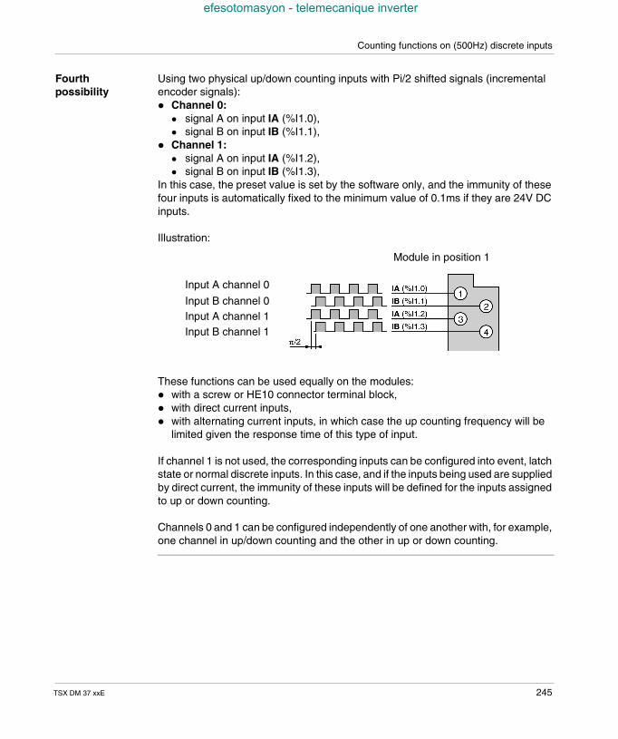
Counting functions on (500Hz) discrete inputs
efesotomasyon - telemecanique inverter
Fourthpossibility
Using two physical up/down counting inputs with Pi/2 shifted signals (incrementalencoder signals): Channel 0:
signal A on input IA (%I1.0), signal B on input IB (%I1.1),
Channel 1: signal A on input IA (%I1.2), signal B on input IB (%I1.3),
In this case, the preset value is set by the software only, and the immunity of thesefour inputs is automatically fixed to the minimum value of 0.1ms if they are 24V DCinputs.
Illustration:
These functions can be used equally on the modules: with a screw or HE10 connector terminal block, with direct current inputs, with alternating current inputs, in which case the up counting frequency will be
limited given the response time of this type of input.
If channel 1 is not used, the corresponding inputs can be configured into event, latchstate or normal discrete inputs. In this case, and if the inputs being used are suppliedby direct current, the immunity of these inputs will be defined for the inputs assignedto up or down counting.
Channels 0 and 1 can be configured independently of one another with, for example,one channel in up/down counting and the other in up or down counting.
Module in position 1
Input A channel 0
Input B channel 0Input A channel 1Input B channel 1
TSX DM 37 xxE 245

Counting functions on (500Hz) discrete inputs
efesotomasyon - telemecanique inverter
246 TSX DM 37 xxE
TSX DM 37 xxE
efesotomasyon - telemecanique inverter
27
Up counting functions built in to(10KHz) TSX 37 22 basesAt a Glance
Aim of thischapter
This chapter deals with the up counting functions which are built in to the (10KHz)TSX 37 22 bases.
What's in thisChapter?
This Chapter contains the following Maps:
Topic Page
Introduction 248
Up or down counting 249
Up/down counting on channels 11 and 12 251
Up/down counting only on channel 11 (first possibility) 252
Up/down counting only on channel 11 (first possibility) 254
Up/down counting only on channel 11 (third possibility) 255
Preset on reference point short cam 257
247
Up counting functions built in to (10KHz) TSX 37 22 bases
efesotomasyon - telemecanique inverter
Introduction
General points The count interfaces of the TSX 37 22 bases can be used to create 2 upcountchannels, 2 downcount channels or independent upcount/downcount channels(channel 11 and channel 12 located in position 0).Each count channel can receive 5 VCC/RS 422 or 24 VCC signals at a maximumfrequency of 10 kHz.Preset inputs can only received 24 VCC signals.
248 TSX DM 37 xxE
Up counting functions built in to (10KHz) TSX 37 22 bases
efesotomasyon - telemecanique inverter
Up or down counting
General points The up or down counting pulses are received on the IA input.Setting to 0 (up counting) or setting the preset value (down counting) can be carriedout according to one of the methods described below: when the status of the input IPres11 is changed for channel 11 (rising or falling
edge, choice made in configuration) and when this is validated in the software, when the status of the IPres12 is changed for channel 12 (rising or falling edge,
choice made in configuration) and when this is validated in the software, automatically as soon as the preset value (up counting) or the value 0 (down
counting) has been reached, this choice being made in configuration, via software.
Note: symbols used in PL7 screens IPres if it is a down counting function, IReset if it is an up counting function.
TSX DM 37 xxE 249
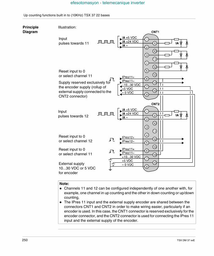
Up counting functions built in to (10KHz) TSX 37 22 bases
efesotomasyon - telemecanique inverter
PrincipleDiagram
Illustration:
Note: Channels 11 and 12 can be configured independently of one another with, for
example, one channel in up counting and the other in down counting or up/downcounting,
The IPres 11 input and the external supply encoder are shared between theconnectors CNT1 and CNT2 in order to make wiring easier, particularly if anencoder is used. In this case, the CNT1 connector is reserved exclusively for theencoder connector, and the CNT2 connector is used for connecting the IPres 11input and the external supply of the encoder.
Inputpulses towards 11
Reset input to 0or select channel 11
Supply reserved exclusively forthe encoder supply (rollup ofexternal supply connected to theCNT2 connector)
Inputpulses towards 12
Reset input to 0or select channel 12
Reset input to 0or select channel 11
External supply10...30 VDC or 5 VDCfor encoder
250 TSX DM 37 xxE
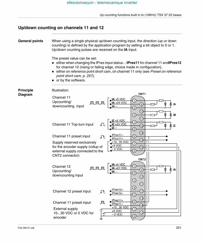
Up counting functions built in to (10KHz) TSX 37 22 bases
efesotomasyon - telemecanique inverter
Up/down counting on channels 11 and 12
General points When using a single physical up/down counting input, the direction (up or downcounting) is defined by the application program by setting a bit object to 0 or 1.Up/down counting pulses are received on the IA input.
The preset value can be set: either when changing the IPres input status..: IPres11 for channel 11 andIPres12
for channel 12 (rising or falling edge, choice made in configuration), either on reference point short cam, on channel 11 only (see Preset on reference
point short cam, p. 257), or by the software.
PrincipleDiagram
Illustration:
Channel 11Upcounting/downcounting input
Channel 11 Top-turn input
Channel 11 preset input
Supply reserved exclusivelyfor the encoder supply (rollup ofexternal supply connected to theCNT2 connector)
Channel 12Upcounting/downcounting input
Channel 12 preset input
External supply10...30 VDC or 5 VDC forencoder
Channel 11 preset input
TSX DM 37 xxE 251
Up counting functions built in to (10KHz) TSX 37 22 bases
efesotomasyon - telemecanique inverter
Up/down counting only on channel 11 (first possibility)
General points When using a single physical up/down counting input, the direction (up or downcounting) is defined by setting the second input to 0 or 1. the up/down counting pulses are received on the IA input, the direction (up or down counting) is defined by positioning of the IB input to
status 1 or 0 (status 1: up count, status 0: down count).
The preset value can be set: either when the status of the IPres11 input is changed (rising or falling edge,
choice made in configuration), or on short cam reference point, or by the software.
252 TSX DM 37 xxE
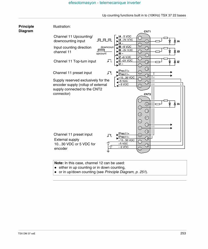
Up counting functions built in to (10KHz) TSX 37 22 bases
efesotomasyon - telemecanique inverter
PrincipleDiagram
Illustration:
Note: In this case, channel 12 can be used: either in up counting or in down counting, or in up/down counting (see Principle Diagram, p. 251).
Channel 11 Upcounting/downcounting input
Input counting directionchannel 11 upcount
downcoun
Channel 11 Top-turn input
Channel 11 preset input
Supply reserved exclusively for theencoder supply (rollup of externalsupply connected to the CNT2connector)
Channel 11 preset inputExternal supply10...30 VDC or 5 VDC forencoder
TSX DM 37 xxE 253
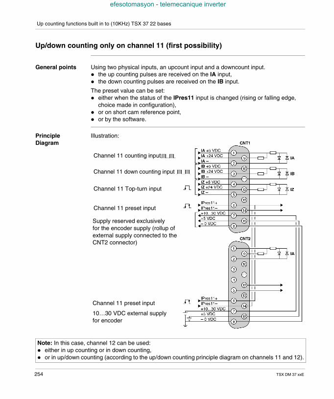
Up counting functions built in to (10KHz) TSX 37 22 bases
efesotomasyon - telemecanique inverter
Up/down counting only on channel 11 (first possibility)
General points Using two physical inputs, an upcount input and a downcount input. the up counting pulses are received on the IA input, the down counting pulses are received on the IB input.
The preset value can be set: either when the status of the IPres11 input is changed (rising or falling edge,
choice made in configuration), or on short cam reference point, or by the software.
PrincipleDiagram
Illustration:
Channel 11 counting input
Channel 11 down counting input
Channel 11 Top-turn input
Channel 11 preset input
Supply reserved exclusivelyfor the encoder supply (rollup ofexternal supply connected to theCNT2 connector)
Channel 11 preset input
10…30 VDC external supplyfor encoder
Note: In this case, channel 12 can be used: either in up counting or in down counting, or in up/down counting (according to the up/down counting principle diagram on channels 11 and 12).
254 TSX DM 37 xxE
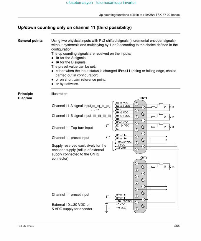
Up counting functions built in to (10KHz) TSX 37 22 bases
efesotomasyon - telemecanique inverter
Up/down counting only on channel 11 (third possibility)
General points Using two physical inputs with Pi/2 shifted signals (incremental encoder signals)without hysteresis and multiplying by 1 or 2 according to the choice defined in theconfiguration.The up counting signals are received on the inputs: IA for the A signals, IA for the B signals.The preset value can be set: either when the input status is changed IPres11 (rising or falling edge, choice
carried out in configuration), or on short cam reference point, or by software.
PrincipleDiagram
Illustration:
Channel 11 A signal input
Channel 11 B signal input
Channel 11 Top-turn input
Channel 11 preset input
Supply reserved exclusively for theencoder supply (rollup of externalsupply connected to the CNT2connector)
Channel 11 preset input
External 10…30 VDC or5 VDC supply for encoder
TSX DM 37 xxE 255
Up counting functions built in to (10KHz) TSX 37 22 bases
efesotomasyon - telemecanique inverter
Note: In this case, channel 12 can be used: either in up counting or in down counting, or in up/down counting (according to the up/down counting principle diagram on channels 11 and 12).
256 TSX DM 37 xxE
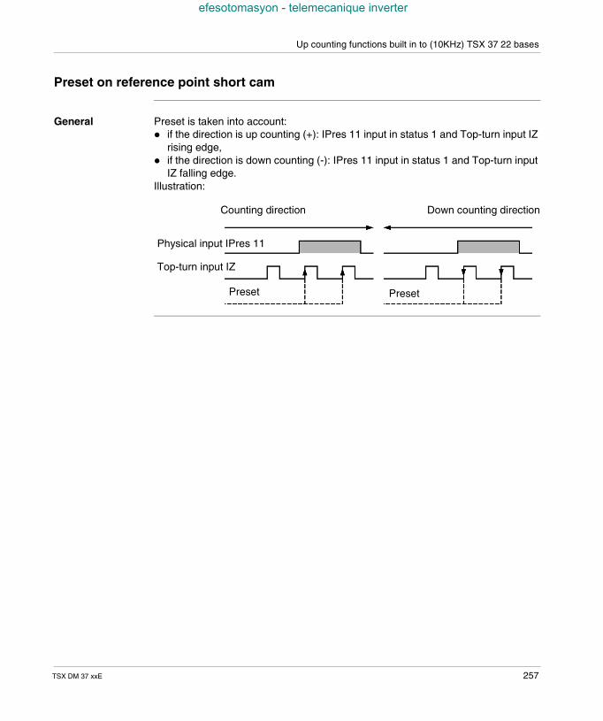
Up counting functions built in to (10KHz) TSX 37 22 bases
efesotomasyon - telemecanique inverter
Preset on reference point short cam
General Preset is taken into account: if the direction is up counting (+): IPres 11 input in status 1 and Top-turn input IZ
rising edge, if the direction is down counting (-): IPres 11 input in status 1 and Top-turn input
IZ falling edge.Illustration:
Counting direction Down counting direction
Preset Preset
Physical input IPres 11
Top-turn input IZ
TSX DM 37 xxE 257

Up counting functions built in to (10KHz) TSX 37 22 bases
efesotomasyon - telemecanique inverter
258 TSX DM 37 xxE
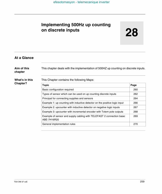
TSX DM 37 xxE
efesotomasyon - telemecanique inverter
28
Implementing 500Hz up countingon discrete inputsAt a Glance
Aim of thischapter
This chapter deals with the implementation of 500HZ up counting on discrete inputs.
What's in thisChapter?
This Chapter contains the following Maps:
Topic Page
Basic configuration required 260
Types of sensor which can be used on up counting discrete inputs 262
Principal for connecting supplies and sensors 264
Example 1: up counting with inductive detector on the positive logic input 266
Example 2: upcounter with inductive detector on negative logic inputs 267
Example 3: upcounter with incremental encoder with Totem pole outputs 268
Example of sensor and supply cabling with TELEFAST 2 connection base:ABE-7H16R20
269
General implementation rules 270
259
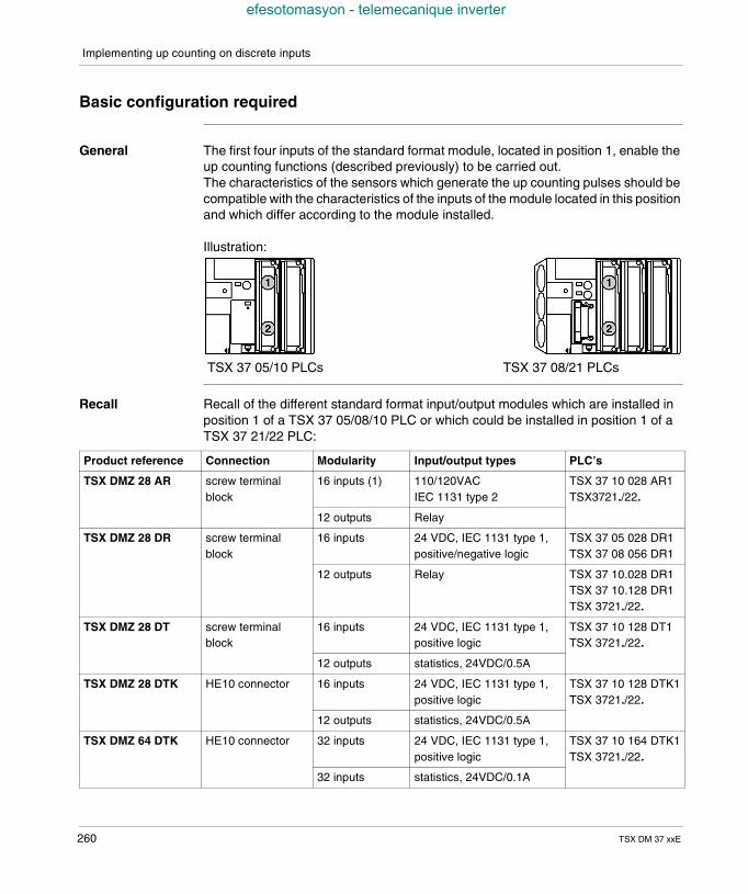
Implementing up counting on discrete inputs
efesotomasyon - telemecanique inverter
Basic configuration required
General The first four inputs of the standard format module, located in position 1, enable theup counting functions (described previously) to be carried out.The characteristics of the sensors which generate the up counting pulses should becompatible with the characteristics of the inputs of the module located in this positionand which differ according to the module installed.
Illustration:
Recall Recall of the different standard format input/output modules which are installed inposition 1 of a TSX 37 05/08/10 PLC or which could be installed in position 1 of aTSX 37 21/22 PLC:
TSX 37 05/10 PLCs TSX 37 08/21 PLCs
Product reference Connection Modularity Input/output types PLC’s
TSX DMZ 28 AR screw terminalblock
16 inputs (1) 110/120VACIEC 1131 type 2
TSX 37 10 028 AR1TSX3721./22.
12 outputs Relay
TSX DMZ 28 DR screw terminalblock
16 inputs 24 VDC, IEC 1131 type 1,positive/negative logic
TSX 37 05 028 DR1TSX 37 08 056 DR1
12 outputs Relay TSX 37 10.028 DR1TSX 37 10.128 DR1TSX 3721./22.
TSX DMZ 28 DT screw terminalblock
16 inputs 24 VDC, IEC 1131 type 1,positive logic
TSX 37 10 128 DT1TSX 3721./22.
12 outputs statistics, 24VDC/0.5A
TSX DMZ 28 DTK HE10 connector 16 inputs 24 VDC, IEC 1131 type 1,positive logic
TSX 37 10 128 DTK1TSX 3721./22.
12 outputs statistics, 24VDC/0.5A
TSX DMZ 64 DTK HE10 connector 32 inputs 24 VDC, IEC 1131 type 1,positive logic
TSX 37 10 164 DTK1TSX 3721./22.
32 inputs statistics, 24VDC/0.1A
260 TSX DM 37 xxE
Implementing up counting on discrete inputs
efesotomasyon - telemecanique inverter
(1) up counting functions possible on these inputs with: voltage-adapted sensors, by limiting the frequency, taking the response time of the sensors into account.
TSX DEZ 32D2 screw terminalblock
32 inputs 24 VDC, IEC 1131 type 2,positive logic
TSX3721./22.
Product reference Connection Modularity Input/output types PLC’s
TSX DM 37 xxE 261
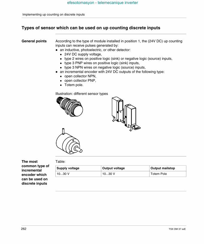
Implementing up counting on discrete inputs
efesotomasyon - telemecanique inverter
Types of sensor which can be used on up counting discrete inputs
General points According to the type of module installed in position 1, the (24V DC) up countinginputs can receive pulses generated by: an inductive, photoelectric, or other detector:
24V DC supply voltage, type 2 wires on positive logic (sink) or negative logic (source) inputs, type 3 PNP wires on positive logic (sink) inputs, type 3 NPN wires on negative logic (source) inputs,
an incremental encoder with 24V DC outputs of the following type: open collector NPN, open collector PNP, Totem pole.
Illustration: different sensor types
The mostcommon type ofincrementalencoder whichcan be used ondiscrete inputs
Table:
Supply voltage Output voltage Output mailstop
10...30 V 10...30 V Totem Pole
262 TSX DM 37 xxE

Implementing up counting on discrete inputs
efesotomasyon - telemecanique inverter
Compatibilityrecall betweenthe sensors andinputs ofdifferentmodules
Table:
For sensor/input compatibility, see (TSX Micro Installation manual, Volume 2).
Modules TSX DMZ 28DR TSX DMZ 28DT/DTKTSX DMZ 64DTK
3 wire PNP sensor type Yes (sink configured inputs) Yes
3 wire NPN sensor type Yes (source configured inputs) No
2 wire sensor type Yes (sink or source configuredinputs)
Yes
Incremental encoder withTotem pole output
Yes (sink configured inputs) Yes
TSX DM 37 xxE 263
Implementing up counting on discrete inputs
efesotomasyon - telemecanique inverter
Principal for connecting supplies and sensors
Modules withscrew terminalblock connection
The supplies and sensors are to be connected directly onto the module’s screwterminal block.
264 TSX DM 37 xxE
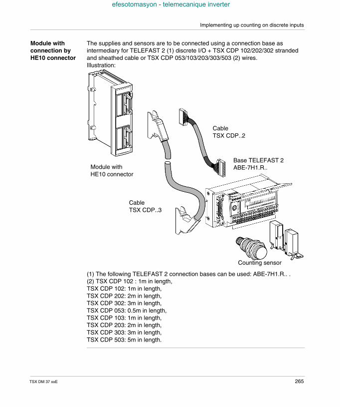
Implementing up counting on discrete inputs
efesotomasyon - telemecanique inverter
Module withconnection byHE10 connector
The supplies and sensors are to be connected using a connection base asintermediary for TELEFAST 2 (1) discrete I/O + TSX CDP 102/202/302 strandedand sheathed cable or TSX CDP 053/103/203/303/503 (2) wires.Illustration:
(1) The following TELEFAST 2 connection bases can be used: ABE-7H1.R.. .(2) TSX CDP 102 : 1m in length,TSX CDP 102: 1m in length,TSX CDP 202: 2m in length,TSX CDP 302: 3m in length,TSX CDP 053: 0.5m in length,TSX CDP 103: 1m in length,TSX CDP 203: 2m in length,TSX CDP 303: 3m in length,TSX CDP 503: 5m in length.
CableTSX CDP..2
Base TELEFAST 2ABE-7H1.R..
Counting sensor
Module withHE10 connector
CableTSX CDP..3
TSX DM 37 xxE 265
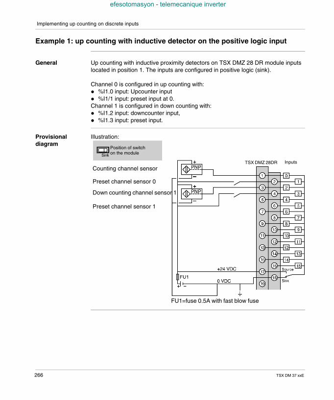
Implementing up counting on discrete inputs
efesotomasyon - telemecanique inverter
Example 1: up counting with inductive detector on the positive logic input
General Up counting with inductive proximity detectors on TSX DMZ 28 DR module inputslocated in position 1. The inputs are configured in positive logic (sink).
Channel 0 is configured in up counting with: %I1.0 input: Upcounter input %I1/1 input: preset input at 0.Channel 1 is configured in down counting with: %I1.2 input: downcounter input, %I1.3 input: preset input.
Provisionaldiagram
Illustration:
Position of switchon the module
TSX DMZ 28DR Inputs
Counting channel sensor
Preset channel sensor 0
Down counting channel sensor 1
Preset channel sensor 1
FU1=fuse 0.5A with fast blow fuse
266 TSX DM 37 xxE
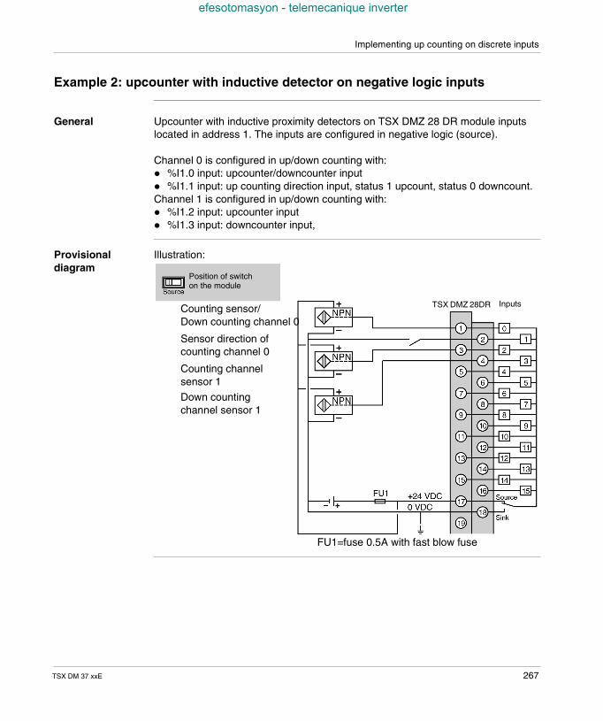
Implementing up counting on discrete inputs
efesotomasyon - telemecanique inverter
Example 2: upcounter with inductive detector on negative logic inputs
General Upcounter with inductive proximity detectors on TSX DMZ 28 DR module inputslocated in address 1. The inputs are configured in negative logic (source).
Channel 0 is configured in up/down counting with: %I1.0 input: upcounter/downcounter input %I1.1 input: up counting direction input, status 1 upcount, status 0 downcount.Channel 1 is configured in up/down counting with: %I1.2 input: upcounter input %I1.3 input: downcounter input,
Provisionaldiagram
Illustration:
Position of switchon the module
Counting sensor/Down counting channel 0
Sensor direction ofcounting channel 0
Counting channelsensor 1
Down countingchannel sensor 1
TSX DMZ 28DR Inputs
FU1=fuse 0.5A with fast blow fuse
TSX DM 37 xxE 267
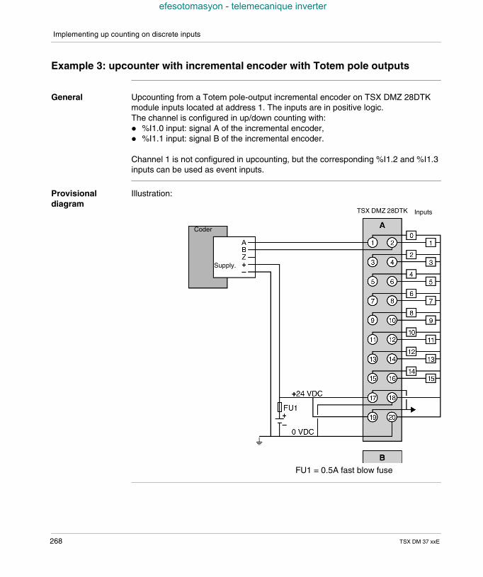
Implementing up counting on discrete inputs
efesotomasyon - telemecanique inverter
Example 3: upcounter with incremental encoder with Totem pole outputs
General Upcounting from a Totem pole-output incremental encoder on TSX DMZ 28DTKmodule inputs located at address 1. The inputs are in positive logic.The channel is configured in up/down counting with: %I1.0 input: signal A of the incremental encoder, %I1.1 input: signal B of the incremental encoder.
Channel 1 is not configured in upcounting, but the corresponding %I1.2 and %I1.3inputs can be used as event inputs.
Provisionaldiagram
Illustration:
TSX DMZ 28DTK Inputs
Coder
Supply.
FU1 = 0.5A fast blow fuse
268 TSX DM 37 xxE
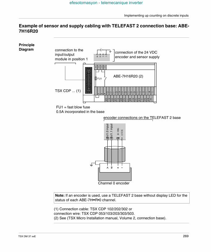
Implementing up counting on discrete inputs
efesotomasyon - telemecanique inverter
Example of sensor and supply cabling with TELEFAST 2 connection base: ABE-7H16R20
PrincipleDiagram
(1) Connection cable: TSX CDP 102/202/302 orconnection wire: TSX CDP 053/103/203/303/503.(2) See (TSX Micro Installation manual, Volume 2, connection base).
Note: If an encoder is used, use a TELEFAST 2 base without display LED for thestatus of each ABE-7H••R•0 channel.
connection of the 24 VDCencoder and sensor supply
connection to theinput/outputmodule in position 1
ABE-7H16R20 (2)
encoder connections on the TELEFAST 2 base
%I1
.0in
put
%I1
.1in
put
TSX CDP ... (1)
FU1 = fast blow fuse0.5A incorporated in the base
Channel 0 encoder
TSX DM 37 xxE 269
Implementing up counting on discrete inputs
efesotomasyon - telemecanique inverter
General implementation rules
General points The general implementation rules are identical to those of the discrete inputs/outputs (TSX Micro Installation manual, Volume 2).The general software implementation rules and the language objects associatedwith the different counting functions are developed in the Manuals TLX DS 57 PL7••E tome 2.
Note: When the inputs of a discrete module are used in upcounting and/ordowncounting mode, outside incremental encoder interface configuration, it isimperative that the filtering on these inputs be suppressed for the 500Hzupcounter.When there is a warm restart, the current value of the upcounter is reset to 0.
270 TSX DM 37 xxE
TSX DM 37 xxE
efesotomasyon - telemecanique inverter
29
Implementing 10KHz upcounteronto TSX 37-22 basesAt a Glance
Aim of thischapter
This chapter deals with the implementation of the 10KHz upcounter onto TSX 37-22bases.
What's in thisChapter?
This Chapter contains the following Maps:
Topic Page
Basic configuration required 272
Type of sensors which can be used on the upcounter inputs 273
Characteristics 274
Pin configuration of the 15-pin SUB-D (channels 11 and 12) connectors 276
Connecting an incremental encoder on channel 11 279
PLC/encoder connection 281
Connecting supply and preset sensor 284
Connecting counting sensors on channel 11 and 12 285
Connecting supplies and sensors on channel 11 286
Connecting supply and sensors on channel 12 287
General rules for implementation 288
271
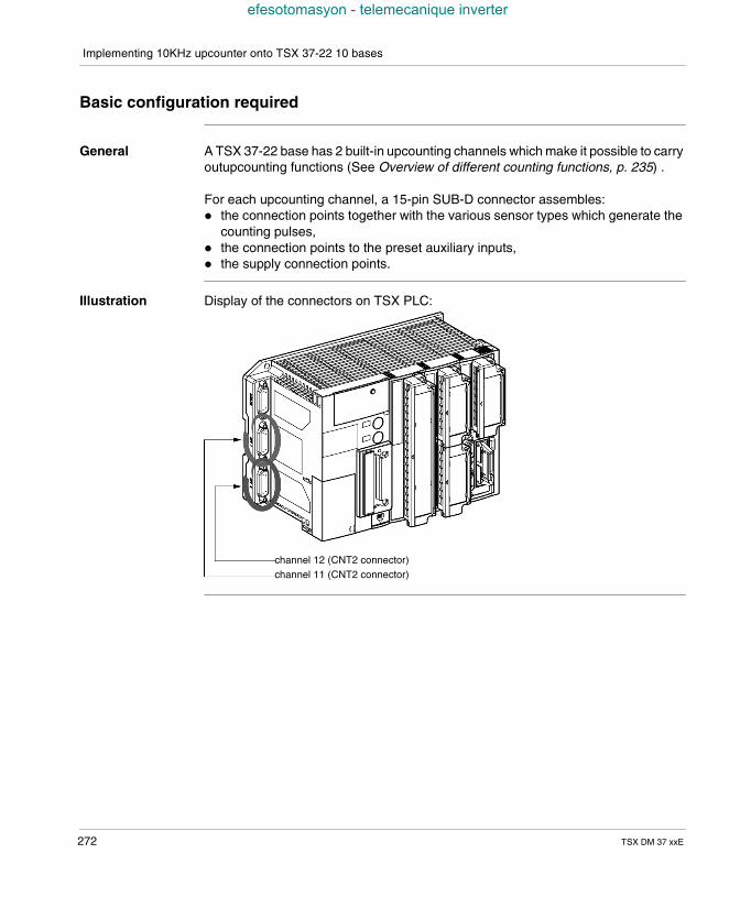
Implementing 10KHz upcounter onto TSX 37-22 10 bases
efesotomasyon - telemecanique inverter
Basic configuration required
General A TSX 37-22 base has 2 built-in upcounting channels which make it possible to carryoutupcounting functions (See Overview of different counting functions, p. 235) .
For each upcounting channel, a 15-pin SUB-D connector assembles: the connection points together with the various sensor types which generate the
counting pulses, the connection points to the preset auxiliary inputs, the supply connection points.
Illustration Display of the connectors on TSX PLC:
channel 12 (CNT2 connector)channel 11 (CNT2 connector)
272 TSX DM 37 xxE
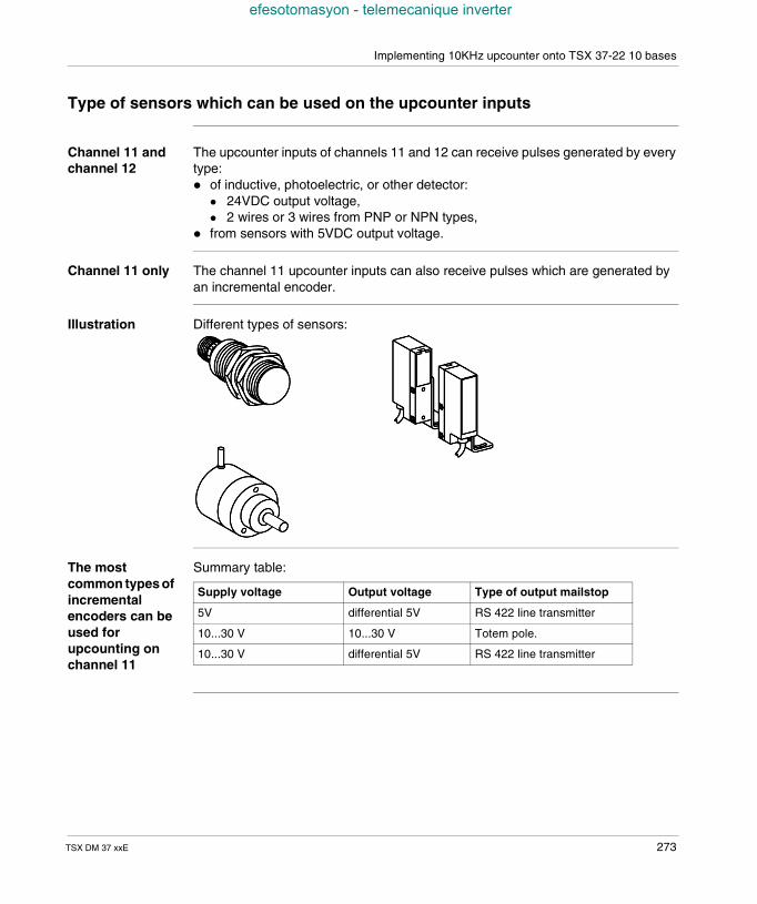
Implementing 10KHz upcounter onto TSX 37-22 10 bases
efesotomasyon - telemecanique inverter
Type of sensors which can be used on the upcounter inputs
Channel 11 andchannel 12
The upcounter inputs of channels 11 and 12 can receive pulses generated by everytype: of inductive, photoelectric, or other detector:
24VDC output voltage, 2 wires or 3 wires from PNP or NPN types,
from sensors with 5VDC output voltage.
Channel 11 only The channel 11 upcounter inputs can also receive pulses which are generated byan incremental encoder.
Illustration Different types of sensors:
The mostcommon types ofincrementalencoders can beused forupcounting onchannel 11
Summary table:
Supply voltage Output voltage Type of output mailstop
5V differential 5V RS 422 line transmitter
10...30 V 10...30 V Totem pole.
10...30 V differential 5V RS 422 line transmitter
TSX DM 37 xxE 273
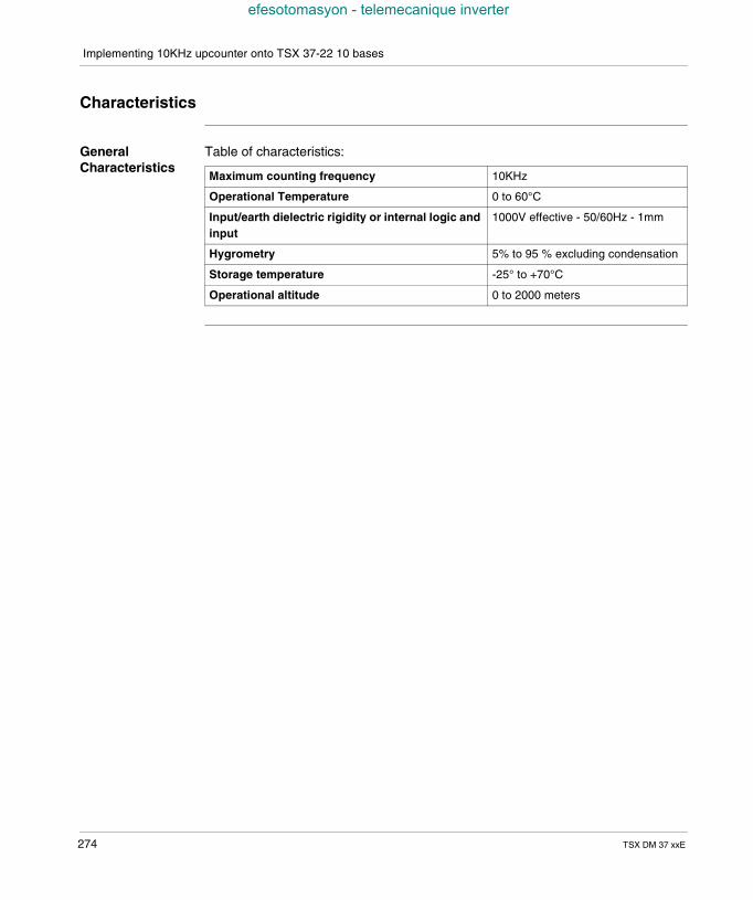
Implementing 10KHz upcounter onto TSX 37-22 10 bases
efesotomasyon - telemecanique inverter
Characteristics
GeneralCharacteristics
Table of characteristics:
Maximum counting frequency 10KHz
Operational Temperature 0 to 60°C
Input/earth dielectric rigidity or internal logic andinput
1000V effective - 50/60Hz - 1mm
Hygrometry 5% to 95 % excluding condensation
Storage temperature -25° to +70°C
Operational altitude 0 to 2000 meters
274 TSX DM 37 xxE
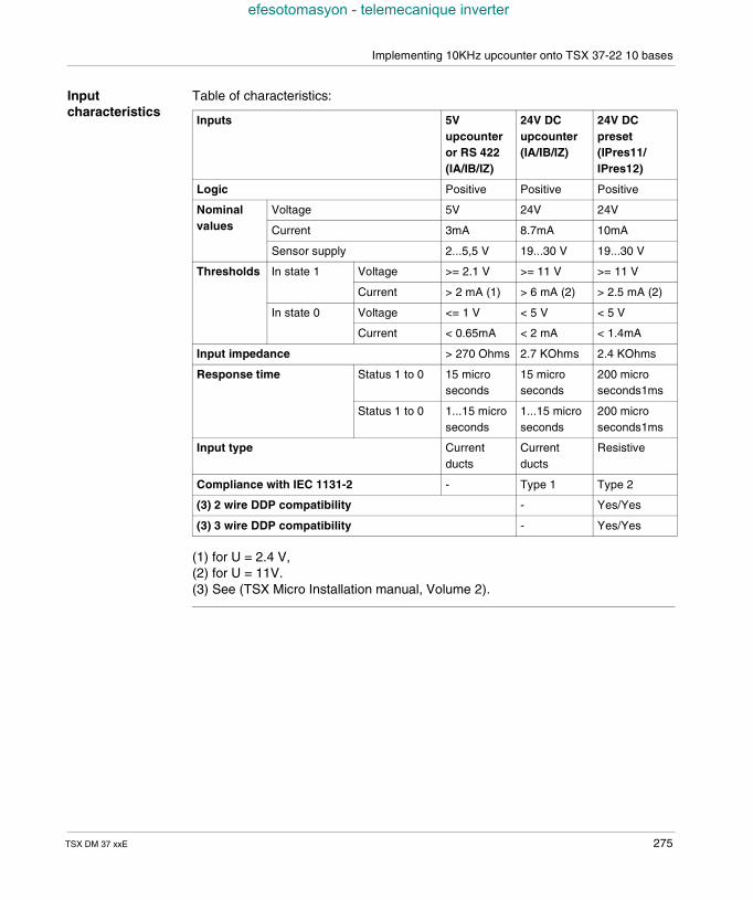
Implementing 10KHz upcounter onto TSX 37-22 10 bases
efesotomasyon - telemecanique inverter
Inputcharacteristics
Table of characteristics:
(1) for U = 2.4 V,(2) for U = 11V.(3) See (TSX Micro Installation manual, Volume 2).
Inputs 5Vupcounteror RS 422(IA/IB/IZ)
24V DCupcounter(IA/IB/IZ)
24V DCpreset(IPres11/IPres12)
Logic Positive Positive Positive
Nominalvalues
Voltage 5V 24V 24V
Current 3mA 8.7mA 10mA
Sensor supply 2...5,5 V 19...30 V 19...30 V
Thresholds In state 1 Voltage >= 2.1 V >= 11 V >= 11 V
Current > 2 mA (1) > 6 mA (2) > 2.5 mA (2)
In state 0 Voltage <= 1 V < 5 V < 5 V
Current < 0.65mA < 2 mA < 1.4mA
Input impedance > 270 Ohms 2.7 KOhms 2.4 KOhms
Response time Status 1 to 0 15 microseconds
15 microseconds
200 microseconds1ms
Status 1 to 0 1...15 microseconds
1...15 microseconds
200 microseconds1ms
Input type Currentducts
Currentducts
Resistive
Compliance with IEC 1131-2 - Type 1 Type 2
(3) 2 wire DDP compatibility - Yes/Yes
(3) 3 wire DDP compatibility - Yes/Yes
TSX DM 37 xxE 275
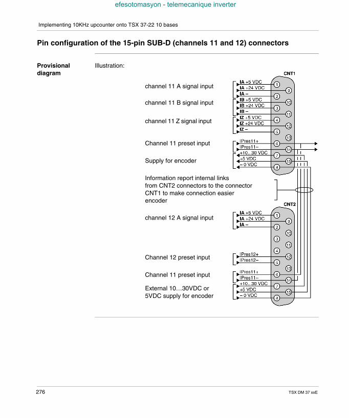
Implementing 10KHz upcounter onto TSX 37-22 10 bases
efesotomasyon - telemecanique inverter
Pin configuration of the 15-pin SUB-D (channels 11 and 12) connectors
Provisionaldiagram
Illustration:
channel 11 A signal input
channel 11 B signal input
channel 11 Z signal input
Channel 11 preset input
Supply for encoder
Information report internal linksfrom CNT2 connectors to the connectorCNT1 to make connection easierencoder
channel 12 A signal input
Channel 12 preset input
Channel 11 preset input
External 10…30VDC or5VDC supply for encoder
276 TSX DM 37 xxE
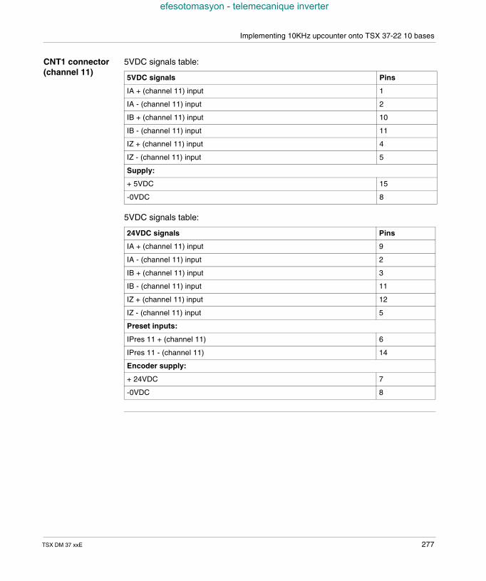
Implementing 10KHz upcounter onto TSX 37-22 10 bases
efesotomasyon - telemecanique inverter
CNT1 connector(channel 11)
5VDC signals table:
5VDC signals table:
5VDC signals Pins
IA + (channel 11) input 1
IA - (channel 11) input 2
IB + (channel 11) input 10
IB - (channel 11) input 11
IZ + (channel 11) input 4
IZ - (channel 11) input 5
Supply:
+ 5VDC 15
-0VDC 8
24VDC signals Pins
IA + (channel 11) input 9
IA - (channel 11) input 2
IB + (channel 11) input 3
IB - (channel 11) input 11
IZ + (channel 11) input 12
IZ - (channel 11) input 5
Preset inputs:
IPres 11 + (channel 11) 6
IPres 11 - (channel 11) 14
Encoder supply:
+ 24VDC 7
-0VDC 8
TSX DM 37 xxE 277
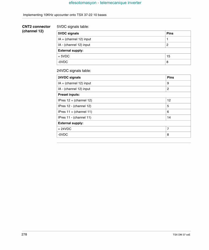
Implementing 10KHz upcounter onto TSX 37-22 10 bases
efesotomasyon - telemecanique inverter
CNT2 connector(channel 12)
5VDC signals table:
24VDC signals table:
5VDC signals Pins
IA + (channel 12) input 1
IA - (channel 12) input 2
External supply:
+ 5VDC 15
-0VDC 8
24VDC signals Pins
IA + (channel 12) input 9
IA - (channel 12) input 2
Preset inputs:
IPres 12 + (channel 12) 12
IPres 12 - (channel 12) 5
IPres 11 + (channel 11) 6
IPres 11 - (channel 11) 14
External supply:
+ 24VDC 7
-0VDC 8
278 TSX DM 37 xxE
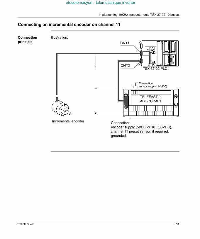
Implementing 10KHz upcounter onto TSX 37-22 10 bases
efesotomasyon - telemecanique inverter
Connecting an incremental encoder on channel 11
Connectionprinciple
Illustration:
CNT1
CNT2TSX 37-22 PLC
Connection:sensor supply (24VDC)
Incremental encoder Connections:encoder supply (5VDC or 10…30VDC),channel 11 preset sensor, if required,grounded.
TELEFAST 2ABE-7CPA01
TSX DM 37 xxE 279
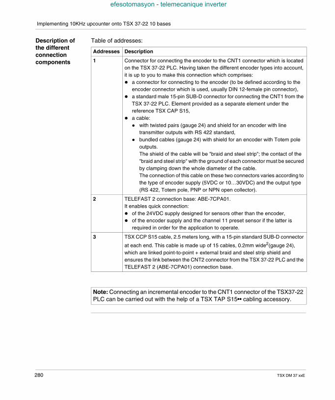
Implementing 10KHz upcounter onto TSX 37-22 10 bases
efesotomasyon - telemecanique inverter
Description ofthe differentconnectioncomponents
Table of addresses:
Addresses Description
1 Connector for connecting the encoder to the CNT1 connector which is locatedon the TSX 37-22 PLC. Having taken the different encoder types into account,it is up to you to make this connection which comprises: a connector for connecting to the encoder (to be defined according to the
encoder connector which is used, usually DIN 12-female pin connector), a standard male 15-pin SUB-D connector for connecting the CNT1 from the
TSX 37-22 PLC. Element provided as a separate element under thereference TSX CAP S15,
a cable: with twisted pairs (gauge 24) and shield for an encoder with line
transmitter outputs with RS 422 standard, bundled cables (gauge 24) with shield for an encoder with Totem pole
outputs.The shield of the cable will be "braid and steel strip"; the contact of the"braid and steel strip" with the ground of each connector must be securedby clamping down the whole diameter of the cable.The connection of this cable on these two connectors varies according tothe type of encoder supply (5VDC or 10…30VDC) and the output type(RS 422, Totem pole, PNP or NPN open collector).
2 TELEFAST 2 connection base: ABE-7CPA01.It enables quick connection: of the 24VDC supply designed for sensors other than the encoder, of the encoder supply and the channel 11 preset sensor if the latter is
required in order for the application to operate.
3 TSX CCP S15 cable, 2.5 meters long, with a 15-pin standard SUB-D connector
at each end. This cable is made up of 15 cables, 0.2mm wide2(gauge 24),which are linked point-to-point + external braid and steel strip shield andensures the link between the CNT2 connector from the TSX 37-22 PLC and theTELEFAST 2 (ABE-7CPA01) connection base.
Note: Connecting an incremental encoder to the CNT1 connector of the TSX37-22PLC can be carried out with the help of a TSX TAP S15•• cabling accessory.
280 TSX DM 37 xxE
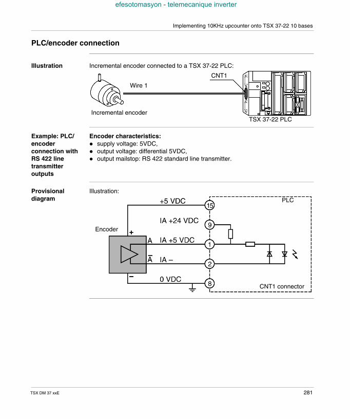
Implementing 10KHz upcounter onto TSX 37-22 10 bases
efesotomasyon - telemecanique inverter
PLC/encoder connection
Illustration Incremental encoder connected to a TSX 37-22 PLC:
Example: PLC/encoderconnection withRS 422 linetransmitteroutputs
Encoder characteristics: supply voltage: 5VDC, output voltage: differential 5VDC, output mailstop: RS 422 standard line transmitter.
Provisionaldiagram
Illustration:
CNT1
TSX 37-22 PLC
Wire 1
Incremental encoder
CNT1 connector
PLC
Encoder
TSX DM 37 xxE 281
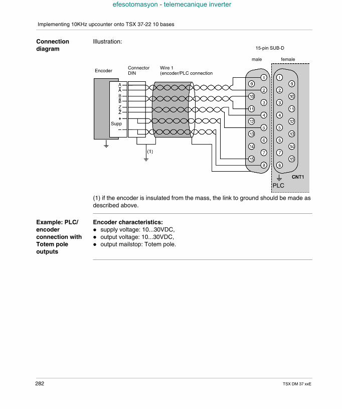
Implementing 10KHz upcounter onto TSX 37-22 10 bases
efesotomasyon - telemecanique inverter
Connectiondiagram
Illustration:
(1) if the encoder is insulated from the mass, the link to ground should be made asdescribed above.
Example: PLC/encoderconnection withTotem poleoutputs
Encoder characteristics: supply voltage: 10...30VDC, output voltage: 10...30VDC, output mailstop: Totem pole.
EncoderConnectorDIN
Wire 1(encoder/PLC connection
15-pin SUB-D
male female
PLC
Supp
282 TSX DM 37 xxE
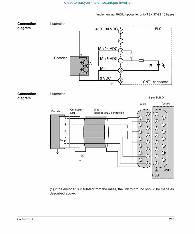
Implementing 10KHz upcounter onto TSX 37-22 10 bases
efesotomasyon - telemecanique inverter
Connectiondiagram
Illustration:
Connectiondiagram
Illustration:
(1) if the encoder is insulated from the mass, the link to ground should be made asdescribed above.
CNT1 connector
PLC
Encoder
EncoderConnectorDIN
Wire 1(encoder/PLC connection
15-pin SUB-D
male female
PLC
Supp
TSX DM 37 xxE 283
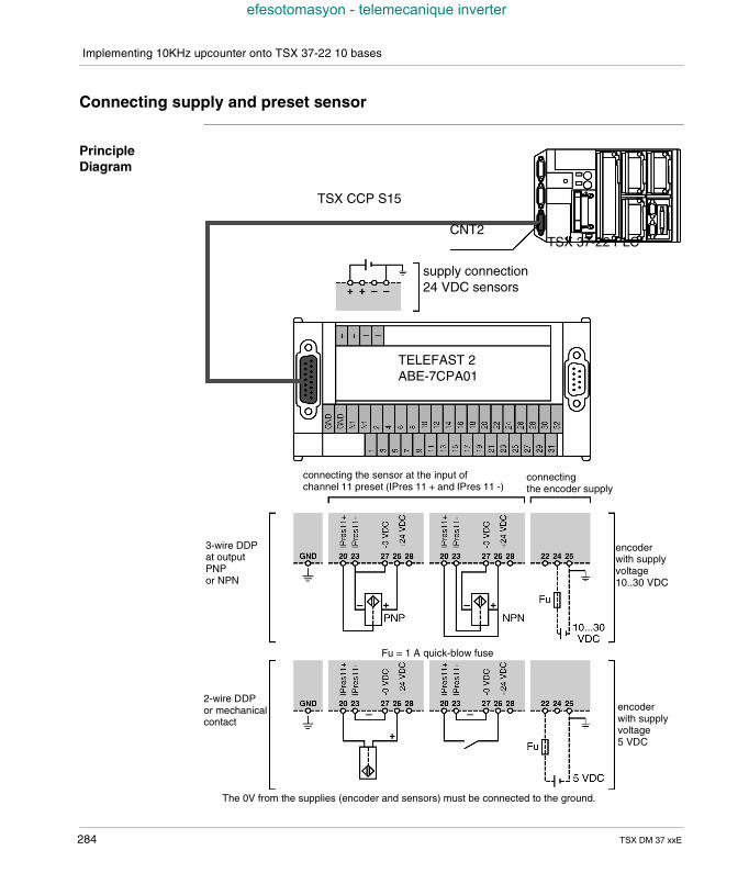
Implementing 10KHz upcounter onto TSX 37-22 10 bases
efesotomasyon - telemecanique inverter
Connecting supply and preset sensor
PrincipleDiagram
TSX CCP S15
CNT2TSX 37-22 PLC
supply connection24 VDC sensors
TELEFAST 2ABE-7CPA01
connecting the sensor at the input ofchannel 11 preset (IPres 11 + and IPres 11 -)
connectingthe encoder supply
3-wire DDPat outputPNPor NPN
2-wire DDPor mechanicalcontact
Fu = 1 A quick-blow fuse
encoderwith supplyvoltage10..30 VDC
encoderwith supplyvoltage5 VDC
The 0V from the supplies (encoder and sensors) must be connected to the ground.
284 TSX DM 37 xxE
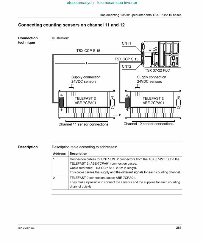
Implementing 10KHz upcounter onto TSX 37-22 10 bases
efesotomasyon - telemecanique inverter
Connecting counting sensors on channel 11 and 12
Connectiontechnique
Illustration:
Description Description table according to addresses:
TSX CCP S 15
CNT1
CNT2
TSX CCP S 15
TSX 37-22 PLC
Supply connection24VDC sensors
Supply connection24VDC sensors
TELEFAST 2ABE-7CPA01
TELEFAST 2ABE-7CPA01
Channel 11 sensor connections Channel 12 sensor connections
Address Description
1 Connection cables for CNT1/CNT2 connectors from the TSX 37-22 PLC to theTELEFAST 2 (ABE-7CPA01) connection bases.Cable reference: TSX CCP S15, 2.5m in length.This cable carries the supply and the different signals for each counting channel.
2 TELEFAST 2 connection bases: ABE-7CPA01.They make it possible to connect the sensors and the supplies for each countingchannel quickly.
TSX DM 37 xxE 285
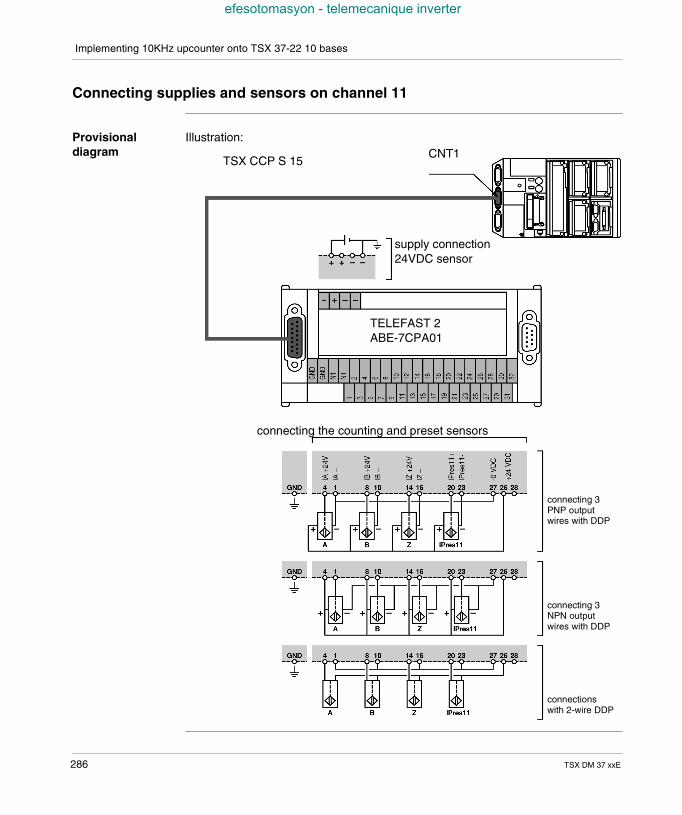
Implementing 10KHz upcounter onto TSX 37-22 10 bases
efesotomasyon - telemecanique inverter
Connecting supplies and sensors on channel 11
Provisionaldiagram
Illustration:CNT1
TSX CCP S 15
supply connection24VDC sensor
TELEFAST 2ABE-7CPA01
connecting the counting and preset sensors
connecting 3PNP outputwires with DDP
connecting 3NPN outputwires with DDP
connectionswith 2-wire DDP
286 TSX DM 37 xxE
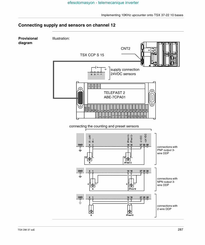
Implementing 10KHz upcounter onto TSX 37-22 10 bases
efesotomasyon - telemecanique inverter
Connecting supply and sensors on channel 12
Provisionaldiagram
Illustration:
TSX CCP S 15
CNT2
supply connection24VDC sensors
TELEFAST 2ABE-7CPA01
connecting the counting and preset sensors
connections withPNP output 3-wire DDP
connections withNPN output 3-wire DDP
connections with2-wire DDP
TSX DM 37 xxE 287
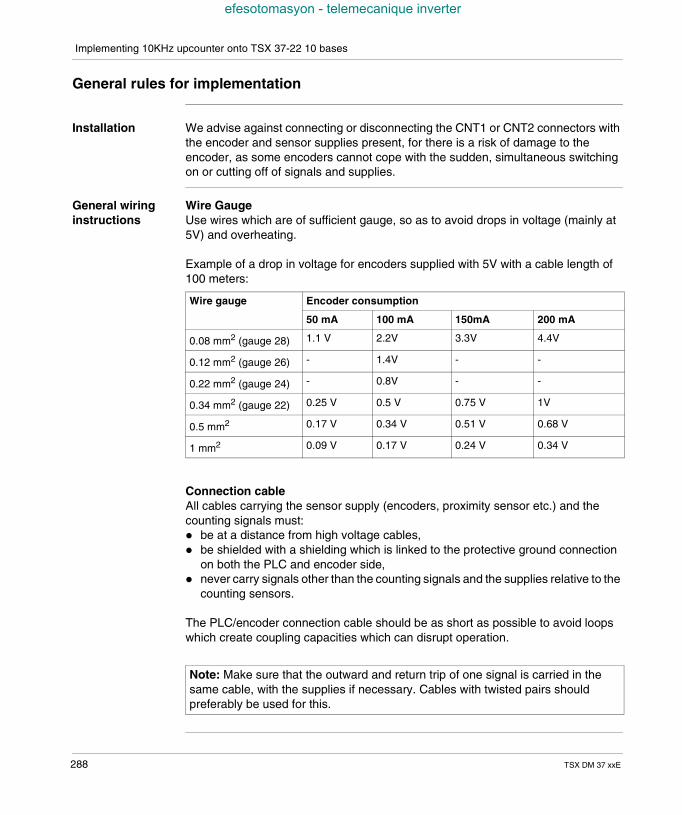
Implementing 10KHz upcounter onto TSX 37-22 10 bases
efesotomasyon - telemecanique inverter
General rules for implementation
Installation We advise against connecting or disconnecting the CNT1 or CNT2 connectors withthe encoder and sensor supplies present, for there is a risk of damage to theencoder, as some encoders cannot cope with the sudden, simultaneous switchingon or cutting off of signals and supplies.
General wiringinstructions
Wire GaugeUse wires which are of sufficient gauge, so as to avoid drops in voltage (mainly at5V) and overheating.
Example of a drop in voltage for encoders supplied with 5V with a cable length of100 meters:
Connection cableAll cables carrying the sensor supply (encoders, proximity sensor etc.) and thecounting signals must: be at a distance from high voltage cables, be shielded with a shielding which is linked to the protective ground connection
on both the PLC and encoder side, never carry signals other than the counting signals and the supplies relative to the
counting sensors.
The PLC/encoder connection cable should be as short as possible to avoid loopswhich create coupling capacities which can disrupt operation.
Wire gauge Encoder consumption
50 mA 100 mA 150mA 200 mA
0.08 mm2 (gauge 28) 1.1 V 2.2V 3.3V 4.4V
0.12 mm2 (gauge 26) - 1.4V - -
0.22 mm2 (gauge 24) - 0.8V - -
0.34 mm2 (gauge 22) 0.25 V 0.5 V 0.75 V 1V
0.5 mm2 0.17 V 0.34 V 0.51 V 0.68 V
1 mm2 0.09 V 0.17 V 0.24 V 0.34 V
Note: Make sure that the outward and return trip of one signal is carried in thesame cable, with the supplies if necessary. Cables with twisted pairs shouldpreferably be used for this.
288 TSX DM 37 xxE
Implementing 10KHz upcounter onto TSX 37-22 10 bases
efesotomasyon - telemecanique inverter
Encoder andauxiliary sensorsupply
Encoder supplyThis must: be reserved exclusively for supplying the encoder, to cut off parasitic pulses
which could disrupt the encoders which contain sensitive electronics, be placed as near as possible to the TELEFAST 2 base to reduce drops in
voltage and couplings with other cables, be protected against short-circuits and overloading by fast-blow fuses, ensure a good autonomy of the power supply in order to avoid micro-power
outages.
Auxiliary sensor supplySee (TSX Micro Installation manual, Volume 2, precautions of use).
SoftwareImplementation
The software implementation and the language objects associated with the differentcounting functions are developed in the Manuals TLX DS 57 PL7 ••E tome 2.
Note: The polarity – 0V DC of encoder and auxiliary sensor supplies must begrounded as close to the supplies as possible.The shielding of the cables carrying the voltages should be grounded.
Note: When the inputs of a discrete module are used in upcounting and/ordowncounting mode, outside incremental encoder interface configuration, it isimperative that the filtering on these inputs be suppressed for the 10KHzupcounter.When there is a warm restart, the current value of the upcounter is reset to 0.
TSX DM 37 xxE 289

Implementing 10KHz upcounter onto TSX 37-22 10 bases
efesotomasyon - telemecanique inverter
290 TSX DM 37 xxE
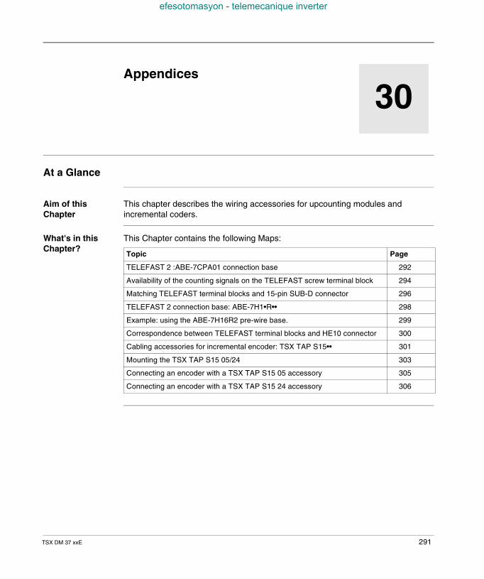
TSX DM 37 xxE
efesotomasyon - telemecanique inverter
30
AppendicesAt a Glance
Aim of thisChapter
This chapter describes the wiring accessories for upcounting modules andincremental coders.
What's in thisChapter?
This Chapter contains the following Maps:
Topic Page
TELEFAST 2 :ABE-7CPA01 connection base 292
Availability of the counting signals on the TELEFAST screw terminal block 294
Matching TELEFAST terminal blocks and 15-pin SUB-D connector 296
TELEFAST 2 connection base: ABE-7H1•R•• 298
Example: using the ABE-7H16R2 pre-wire base. 299
Correspondence between TELEFAST terminal blocks and HE10 connector 300
Cabling accessories for incremental encoder: TSX TAP S15•• 301
Mounting the TSX TAP S15 05/24 303
Connecting an encoder with a TSX TAP S15 05 accessory 305
Connecting an encoder with a TSX TAP S15 24 accessory 306
291
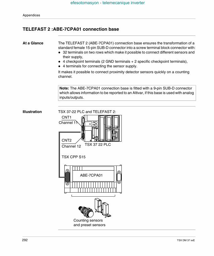
Appendices
efesotomasyon - telemecanique inverter
TELEFAST 2 :ABE-7CPA01 connection base
At a Glance The TELEFAST 2 (ABE-7CPA01) connection base ensures the transformation of astandard female 15-pin SUB-D connector into a screw terminal block connector with: 32 terminals on two rows which make it possible to connect different sensors and
their supply, 4 checkpoint terminals (2 GND terminals + 2 specific checkpoint terminals), 4 terminals for connecting the sensor supply.
It makes it possible to connect proximity detector sensors quickly on a countingchannel.
Illustration TSX 37-22 PLC and TELEFAST 2:
Note: The ABE-7CPA01 connection base is fitted with a 9-pin SUB-D connectorwhich allows information to be reported to an Altivar, if this base is used with analoginputs/outputs.
TSX 37 22 PLC
CNT1Channel 11
CNT2
Channel 12
TSX CPP S15
ABE-7CPA01
Counting sensorsand preset sensors
292 TSX DM 37 xxE
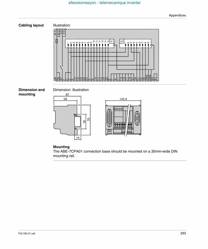
Appendices
efesotomasyon - telemecanique inverter
Cabling layout Illustration:
Dimension andmounting
Dimension: illustration
MountingThe ABE-7CPA01 connection base should be mounted on a 35mm-wide DINmounting rail.
TSX DM 37 xxE 293
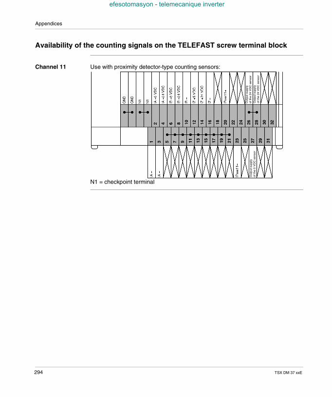
Appendices
efesotomasyon - telemecanique inverter
Availability of the counting signals on the TELEFAST screw terminal block
Channel 11 Use with proximity detector-type counting sensors:
N1 = checkpoint terminal
Out
puts
uppl
yof
the
24V
DC
sens
or
Out
puts
uppl
yof
the
24V
DC
sens
or
Out
puts
uppl
yof
the
0V
DC
sens
or
294 TSX DM 37 xxE
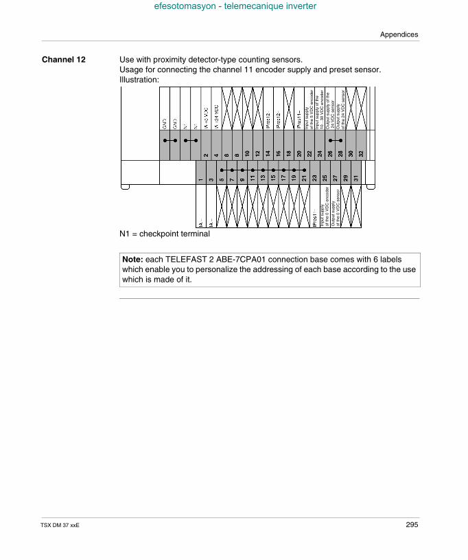
Appendices
efesotomasyon - telemecanique inverter
Channel 12 Use with proximity detector-type counting sensors.Usage for connecting the channel 11 encoder supply and preset sensor.Illustration:
N1 = checkpoint terminal
Note: each TELEFAST 2 ABE-7CPA01 connection base comes with 6 labelswhich enable you to personalize the addressing of each base according to the usewhich is made of it.
Inpu
tsup
ply
ofth
e5
VD
Cen
code
rIn
puts
uppl
yof
the
10…
30V
DC
enco
der
Out
puts
uppl
yof
the
24V
DC
sens
orO
utpu
tsup
ply
ofth
e24
VD
Cse
nsor
Inpu
tsup
ply
ofth
e0
VD
Cen
code
r
Out
puts
uppl
yof
the
0V
DC
sens
or
TSX DM 37 xxE 295
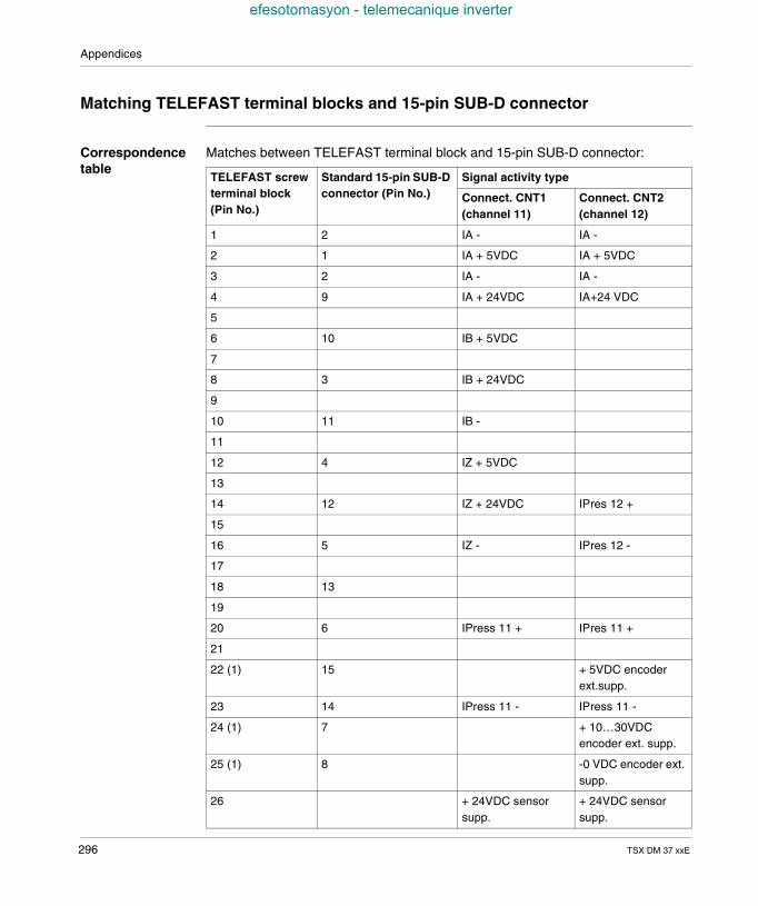
Appendices
efesotomasyon - telemecanique inverter
Matching TELEFAST terminal blocks and 15-pin SUB-D connector
Correspondencetable
Matches between TELEFAST terminal block and 15-pin SUB-D connector:
TELEFAST screwterminal block(Pin No.)
Standard 15-pin SUB-Dconnector (Pin No.)
Signal activity type
Connect. CNT1(channel 11)
Connect. CNT2(channel 12)
1 2 IA - IA -
2 1 IA + 5VDC IA + 5VDC
3 2 IA - IA -
4 9 IA + 24VDC IA+24 VDC
5
6 10 IB + 5VDC
7
8 3 IB + 24VDC
9
10 11 IB -
11
12 4 IZ + 5VDC
13
14 12 IZ + 24VDC IPres 12 +
15
16 5 IZ - IPres 12 -
17
18 13
19
20 6 IPress 11 + IPres 11 +
21
22 (1) 15 + 5VDC encoderext.supp.
23 14 IPress 11 - IPress 11 -
24 (1) 7 + 10…30VDCencoder ext. supp.
25 (1) 8 -0 VDC encoder ext.supp.
26 + 24VDC sensorsupp.
+ 24VDC sensorsupp.
296 TSX DM 37 xxE
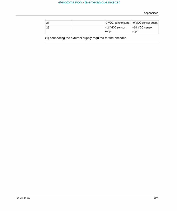
Appendices
efesotomasyon - telemecanique inverter
(1) connecting the external supply required for the encoder.
27 -0 VDC sensor supp. -0 VDC sensor supp.
28 + 24VDC sensorsupp.
+24 VDC sensorsupp.
TSX DM 37 xxE 297
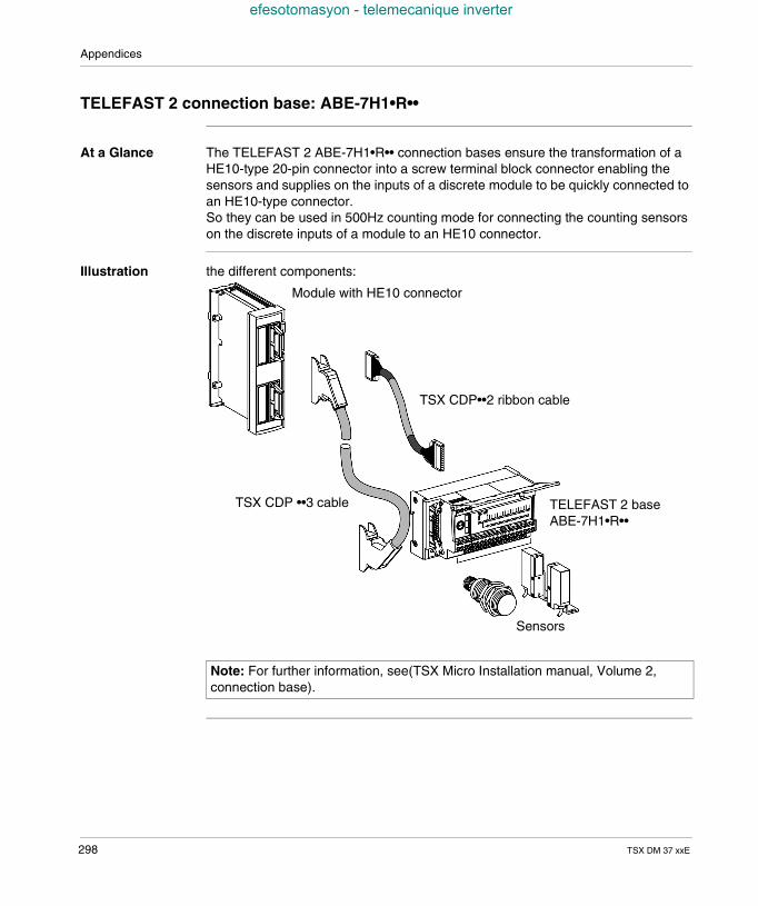
Appendices
efesotomasyon - telemecanique inverter
TELEFAST 2 connection base: ABE-7H1•R••
At a Glance The TELEFAST 2 ABE-7H1•R•• connection bases ensure the transformation of aHE10-type 20-pin connector into a screw terminal block connector enabling thesensors and supplies on the inputs of a discrete module to be quickly connected toan HE10-type connector.So they can be used in 500Hz counting mode for connecting the counting sensorson the discrete inputs of a module to an HE10 connector.
Illustration the different components:
Note: For further information, see(TSX Micro Installation manual, Volume 2,connection base).
Module with HE10 connector
TSX CDP ••3 cable
TSX CDP••2 ribbon cable
TELEFAST 2 baseABE-7H1•R••
Sensors
298 TSX DM 37 xxE
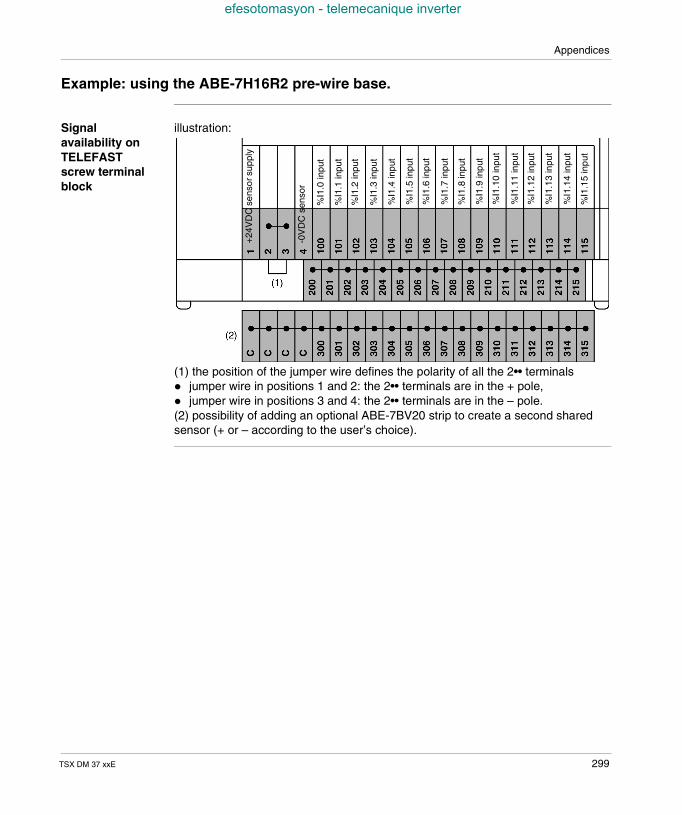
Appendices
efesotomasyon - telemecanique inverter
Example: using the ABE-7H16R2 pre-wire base.
Signalavailability onTELEFASTscrew terminalblock
illustration:
(1) the position of the jumper wire defines the polarity of all the 2•• terminals jumper wire in positions 1 and 2: the 2•• terminals are in the + pole, jumper wire in positions 3 and 4: the 2•• terminals are in the – pole.(2) possibility of adding an optional ABE-7BV20 strip to create a second sharedsensor (+ or – according to the user’s choice).
+24
VD
Cse
nsor
supp
ly
-0V
DC
sens
or
%I1
.0in
put
%I1
.15
inpu
t
%I1
.1in
put
%I1
.2in
put
%I1
.3in
put
%I1
.4in
put
%I1
.5in
put
%I1
.6in
put
%I1
.7in
put
%I1
.8in
put
%I1
.9in
put
%I1
.10
inpu
t
%I1
.11
inpu
t
%I1
.14
inpu
t
%I1
.13
inpu
t
%I1
.12
inpu
t
TSX DM 37 xxE 299
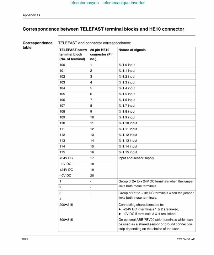
Appendices
efesotomasyon - telemecanique inverter
Correspondence between TELEFAST terminal blocks and HE10 connector
Correspondencetable
TELEFAST and connector correspondence:
TELEFAST screwterminal block(No. of terminal)
20-pin HE10connector (Pinno.)
Nature of signals
100 1 %I1.0 input
101 2 %I1.1 input
102 3 %I1.2 input
103 4 %I1.3 input
104 5 %I1.4 input
105 6 %I1.5 input
106 7 %I1.6 input
107 8 %I1.7 input
108 9 %I1.8 input
109 10 %I1.9 input
110 11 %I1.10 input
111 12 %I1.11 input
112 13 %I1.12 input
113 14 %I1.13 input
114 15 %I1.14 input
115 16 %I1.15 input
+24V DC 17 Input and sensor supply.
- 0V DC 18
+24V DC 19
- 0V DC 20
1 - Group of 2•• to + 24V DC terminals when the jumperlinks both these terminals.2 -
3 - Group of 2•• to + 0V DC terminals when the jumperlinks both these terminals.4 -
200••215 - Connecting shared sensors to: +24V DC if terminals 1 & 2 are linked, -0V DC if terminals 3 & 4 are linked.
300••315 - On optional ABE-7BV20 strip: terminals which canbe used as a shared sensor or ground connectionstrip depending on the choice of the user.
300 TSX DM 37 xxE
Appendices
efesotomasyon - telemecanique inverter
Cabling accessories for incremental encoder: TSX TAP S15••
At a Glance The TSX TAP 15•• cabling accessories are connecting devices for an incrementalencoder with Totem pole (or push-pull) outputs : TSX TAP S15 05: cabling accessory for an incremental encoder with a 5VDC
supply, TSX TAP S15 24: cabling accessory for an incremental encoder with a 24VDC
supply (or 10…30VDC).
The TSX TAP S15 05/24 have 2 connectors: a female 12-pin DIN connector which allows the encoder cable to be screwed in
a clockwise direction (the ring fastener is on the encoder cable), a standard 15-pin SUB-D connector which allows (using a standard TSX CCP
S15 cable) the TSX 3722 PLC base to be connected to the SUB-D (addressCNT1) connector.
Detailsconcerning theconnectors
The number of these connector pins can be addressed in two different ways. Themajority of the encoders have a built in 12-pin DIN base, addressing is carried outin an anti-clockwise direction. The TSX TAP S15 has a female 12-pin DIN baseaddressed in an anti-clockwise direction. All the user cords must be fitted withcoupling ports addressed in a clockwise direction, which makes the pin numberscorrespond one by one when cabling.
Note: These products, TSX TAP S15 05/24, can be fixed onto a Din rail, using aset square which is supplied with the product, or they can be fixed across thecabinet with a gasket which is supplied with the product.
TSX DM 37 xxE 301
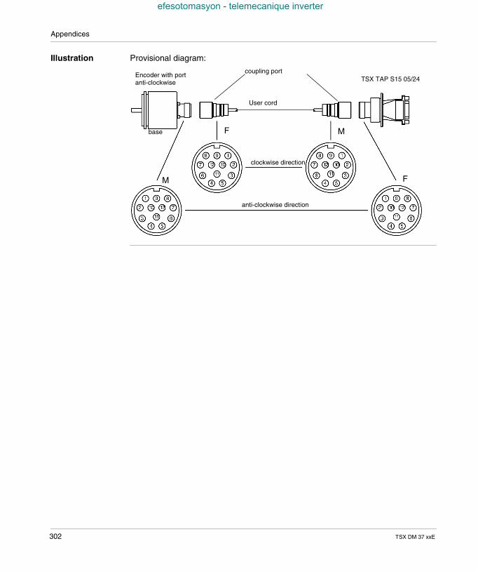
Appendices
efesotomasyon - telemecanique inverter
Illustration Provisional diagram:
clockwise direction
anti-clockwise direction
M
F M
F
Encoder with portanti-clockwise
base
User cord
TSX TAP S15 05/24coupling port
302 TSX DM 37 xxE
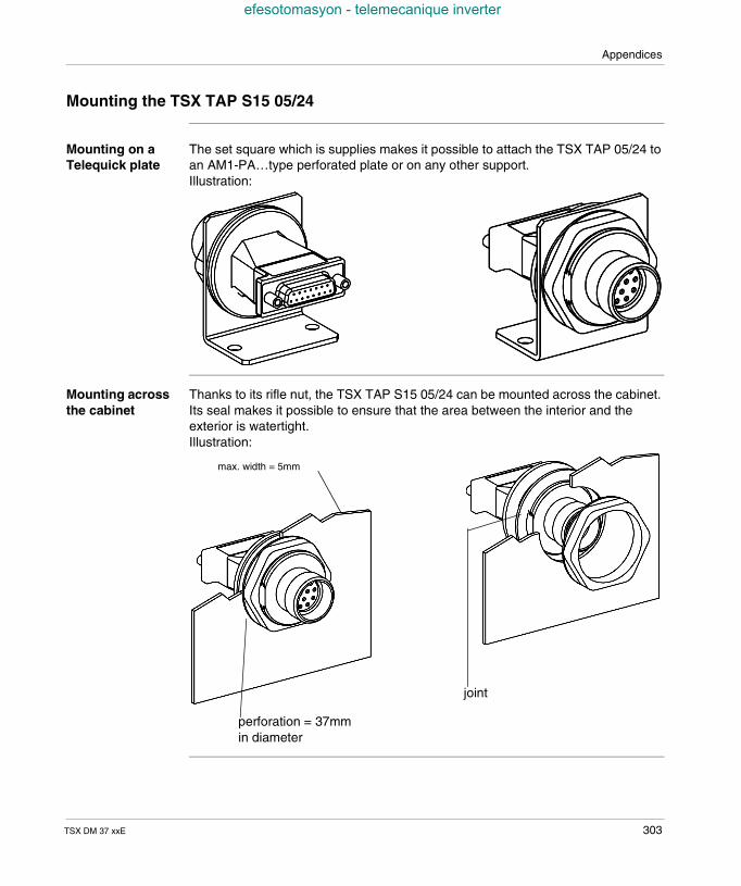
Appendices
efesotomasyon - telemecanique inverter
Mounting the TSX TAP S15 05/24
Mounting on aTelequick plate
The set square which is supplies makes it possible to attach the TSX TAP 05/24 toan AM1-PA…type perforated plate or on any other support.Illustration:
Mounting acrossthe cabinet
Thanks to its rifle nut, the TSX TAP S15 05/24 can be mounted across the cabinet.Its seal makes it possible to ensure that the area between the interior and theexterior is watertight.Illustration:
max. width = 5mm
perforation = 37mmin diameter
joint
TSX DM 37 xxE 303
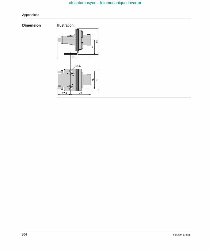
Appendices
efesotomasyon - telemecanique inverter
Dimension Illustration:
304 TSX DM 37 xxE
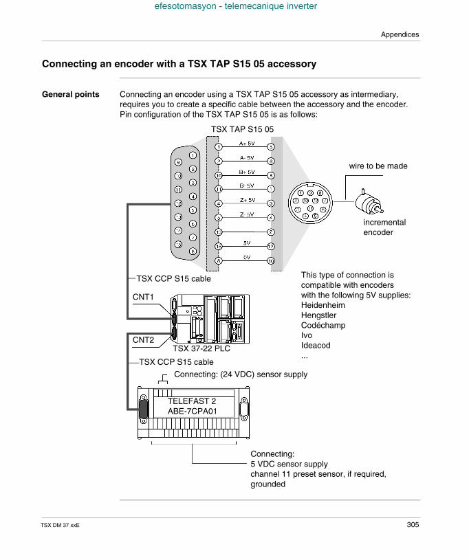
Appendices
efesotomasyon - telemecanique inverter
Connecting an encoder with a TSX TAP S15 05 accessory
General points Connecting an encoder using a TSX TAP S15 05 accessory as intermediary,requires you to create a specific cable between the accessory and the encoder.Pin configuration of the TSX TAP S15 05 is as follows:
TSX CCP S15 cable
CNT1
CNT2TSX 37-22 PLC
wire to be made
incrementalencoder
TSX CCP S15 cable
Connecting: (24 VDC) sensor supply
TELEFAST 2ABE-7CPA01
Connecting:5 VDC sensor supplychannel 11 preset sensor, if required,grounded
This type of connection iscompatible with encoderswith the following 5V supplies:HeidenheimHengstlerCodéchampIvoIdeacod...
TSX TAP S15 05
TSX DM 37 xxE 305
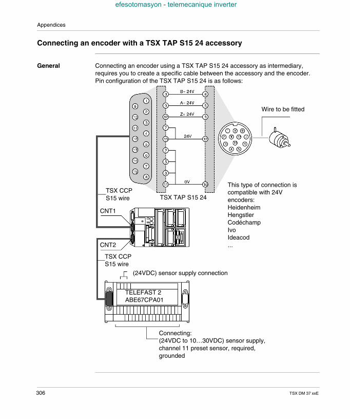
Appendices
efesotomasyon - telemecanique inverter
Connecting an encoder with a TSX TAP S15 24 accessory
General Connecting an encoder using a TSX TAP S15 24 accessory as intermediary,requires you to create a specific cable between the accessory and the encoder.Pin configuration of the TSX TAP S15 24 is as follows:
Wire to be fitted
TSX TAP S15 24TSX CCPS15 wire
CNT1
CNT2
TSX CCPS15 wire
(24VDC) sensor supply connection
Connecting:(24VDC to 10…30VDC) sensor supply,channel 11 preset sensor, required,grounded
TELEFAST 2ABE67CPA01
This type of connection iscompatible with 24Vencoders:HeidenheimHengstlerCodéchampIvoIdeacod...
306 TSX DM 37 xxE
TSX DM 37 xxE
efesotomasyon - telemecanique inverter
VII
Communication incorporated inthe basesAim of this tab
Aim of this tab This tab deals with the means of communication incorporated into Micro PLCs
What's in thispart?
This Part contains the following Chapters:
Chapter Chaptername Page
31 Terminal port 309
32 TSX unit P ACC 01 345
307

Communication incorporated in the bases
efesotomasyon - telemecanique inverter
308 TSX DM 37 xxE
TSX DM 37 xxE
efesotomasyon - telemecanique inverter
31
Terminal portOverview of this chapter
Aim of thischapter
This chapter deals with the terminal ports assigned to Micro PLC’s.
What's in thisChapter?
This Chapter contains the following Sections:
Section Topic Page
31.1 Micro communication 310
31.2 Connections 319
31.3 Attachments 340
309
Terminal port
efesotomasyon - telemecanique inverter
31.1 Micro communication
At a Glance
Subject of thissection
This section provides an overview of the different communication protocols availablefrom the terminal port.
What's in thisSection?
This Section contains the following Maps:
Topic Page
Foreword 311
At a Glance 312
Communication with a terminal 314
Communication with an operator dialog console 315
Communication UNI-TELWAY master/slave 316
Communication character string 317
Communication Modbus/JBus 318
310 TSX DM 37 xxE
Terminal port
efesotomasyon - telemecanique inverter
Foreword
General points As the terminal port refers to the UNI-TELWAY master, UNI-TELWAY slave,Modbus and character string communication modes, it is necessary to consult thefollowing documents for the implementation (hardware and software) of thesedifferent modes of communication. TSX DG UTW F : UNI-TELWAY Communication Bus (User guide), TSX DR NET F : X-WAY communication (Reference manual), TSX DS COM PL7 ••F : Micro/Premium PLC communication (implementation
manual).
TSX DM 37 xxE 311
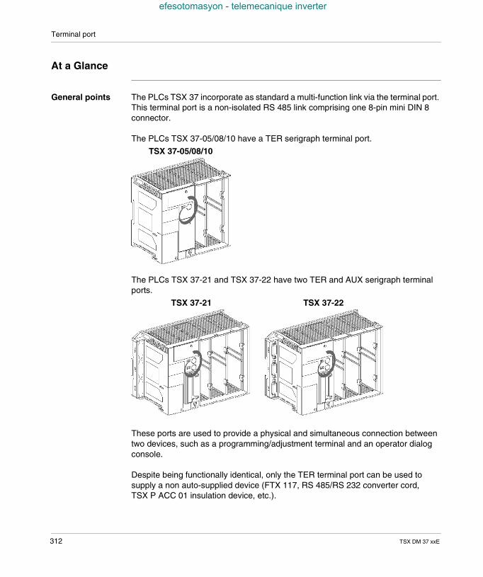
Terminal port
efesotomasyon - telemecanique inverter
At a Glance
General points The PLCs TSX 37 incorporate as standard a multi-function link via the terminal port.This terminal port is a non-isolated RS 485 link comprising one 8-pin mini DIN 8connector.
The PLCs TSX 37-05/08/10 have a TER serigraph terminal port.
The PLCs TSX 37-21 and TSX 37-22 have two TER and AUX serigraph terminalports.
These ports are used to provide a physical and simultaneous connection betweentwo devices, such as a programming/adjustment terminal and an operator dialogconsole.
Despite being functionally identical, only the TER terminal port can be used tosupply a non auto-supplied device (FTX 117, RS 485/RS 232 converter cord,TSX P ACC 01 insulation device, etc.).
TSX 37-05/08/10
TSX 37-21 TSX 37-22
312 TSX DM 37 xxE
Terminal port
efesotomasyon - telemecanique inverter
The terminal port operates by default in UNI-TELWAY master mode. The switch toUNI-TELWAY slave mode, Modbus/JBus mode or character mode is performed onset-up.
Note: The communication mode (UNI-TELWAY master, UNI-TELWAY slave,Modbus/Jbus or character mode) is identical on the two TER and AUX connectors.
TSX DM 37 xxE 313
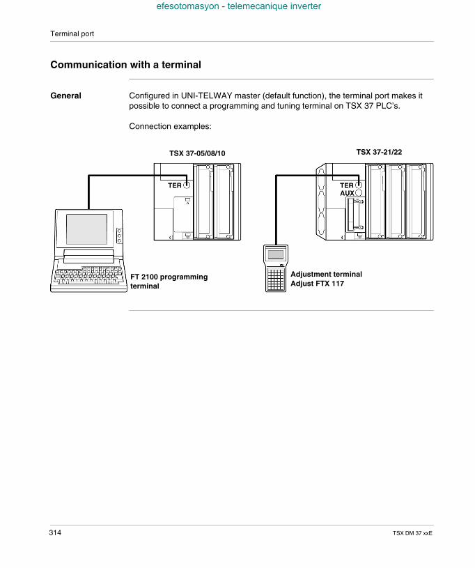
Terminal port
efesotomasyon - telemecanique inverter
Communication with a terminal
General Configured in UNI-TELWAY master (default function), the terminal port makes itpossible to connect a programming and tuning terminal on TSX 37 PLC’s.
Connection examples:
FT 2100 programmingterminal
Adjustment terminalAdjust FTX 117
TSX 37-05/08/10 TSX 37-21/22
314 TSX DM 37 xxE
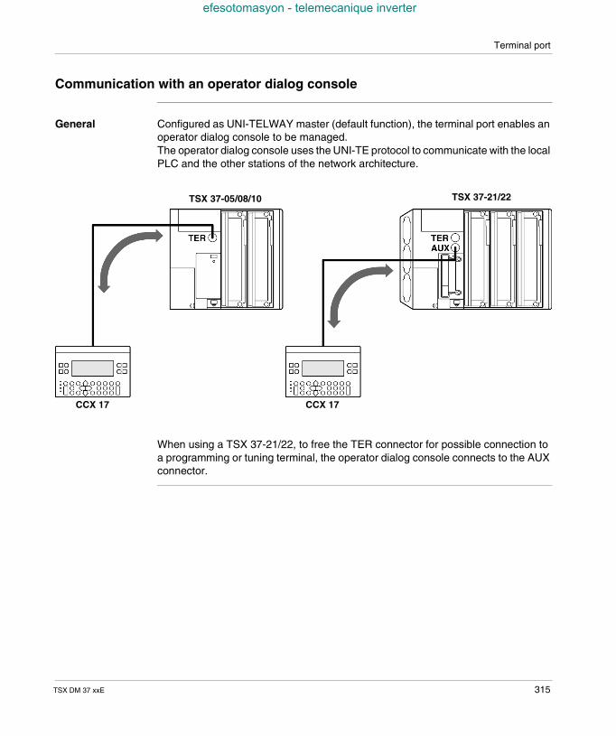
Terminal port
efesotomasyon - telemecanique inverter
Communication with an operator dialog console
General Configured as UNI-TELWAY master (default function), the terminal port enables anoperator dialog console to be managed.The operator dialog console uses the UNI-TE protocol to communicate with the localPLC and the other stations of the network architecture.
When using a TSX 37-21/22, to free the TER connector for possible connection toa programming or tuning terminal, the operator dialog console connects to the AUXconnector.
CCX 17CCX 17
TSX 37-05/08/10 TSX 37-21/22
TSX DM 37 xxE 315
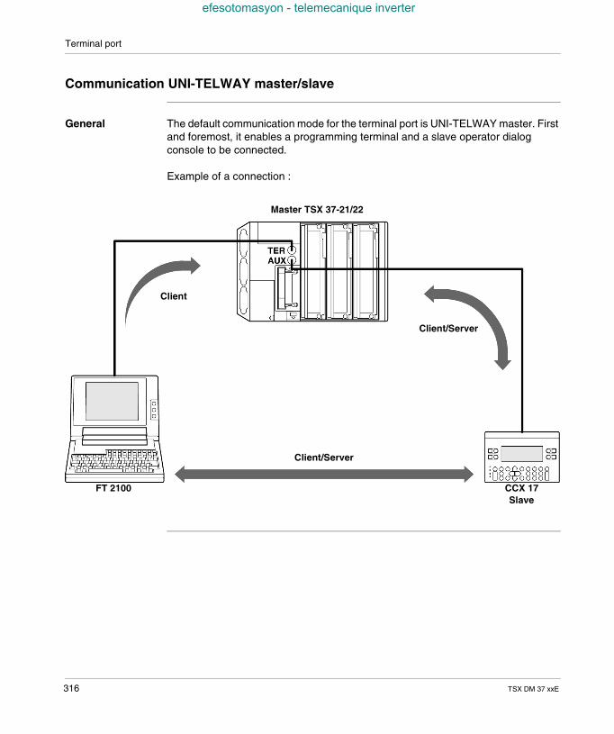
Terminal port
efesotomasyon - telemecanique inverter
Communication UNI-TELWAY master/slave
General The default communication mode for the terminal port is UNI-TELWAY master. Firstand foremost, it enables a programming terminal and a slave operator dialogconsole to be connected.
Example of a connection :
FT 2100 CCX 17Slave
Master TSX 37-21/22
Client/Server
Client/Server
Client
316 TSX DM 37 xxE
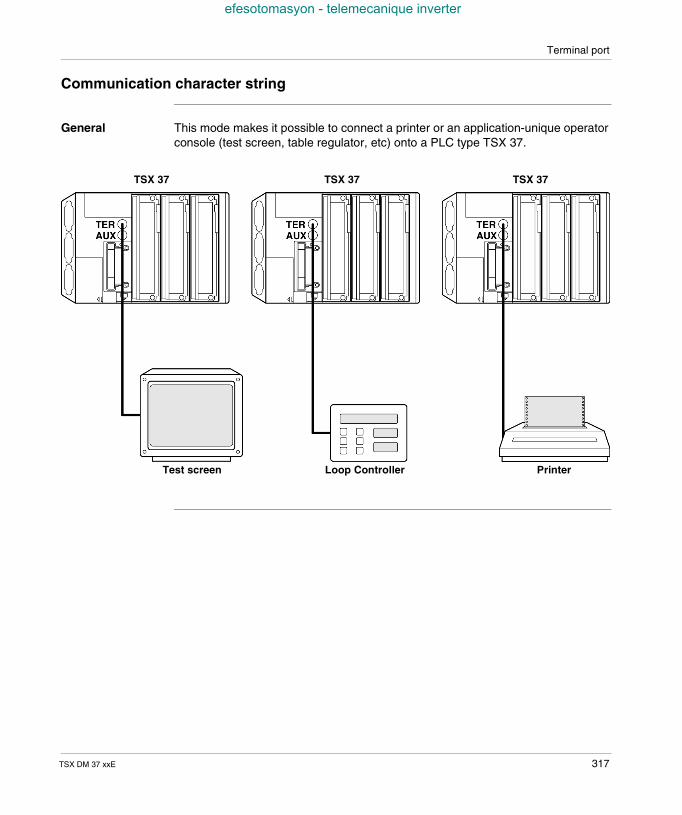
Terminal port
efesotomasyon - telemecanique inverter
Communication character string
General This mode makes it possible to connect a printer or an application-unique operatorconsole (test screen, table regulator, etc) onto a PLC type TSX 37.
Test screen Loop Controller
TSX 37
Printer
TSX 37 TSX 37
TSX DM 37 xxE 317
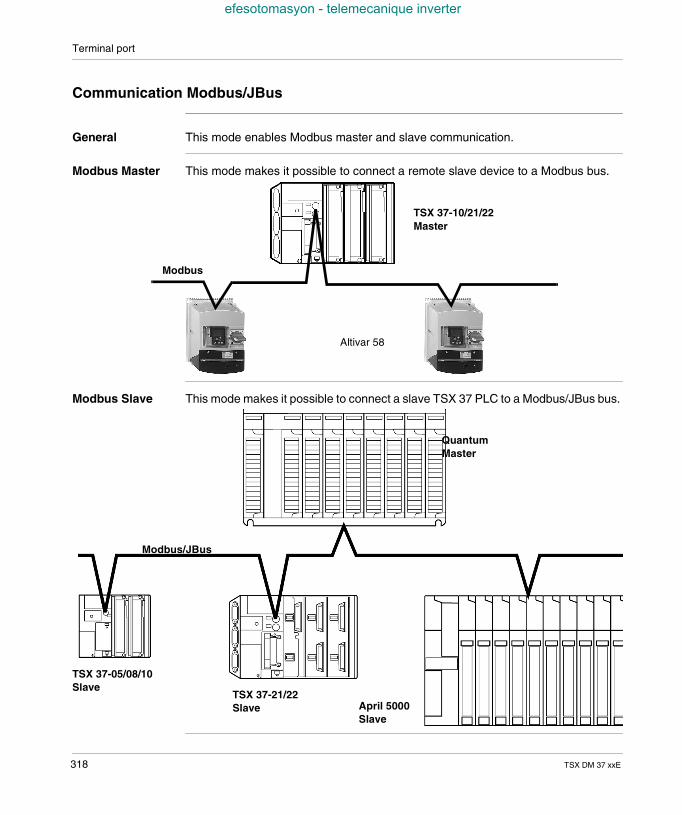
Terminal port
efesotomasyon - telemecanique inverter
Communication Modbus/JBus
General This mode enables Modbus master and slave communication.
Modbus Master This mode makes it possible to connect a remote slave device to a Modbus bus.
Modbus Slave This mode makes it possible to connect a slave TSX 37 PLC to a Modbus/JBus bus.
TSX 37-10/21/22Master
Modbus
Altivar 58
TSX 37-21/22Slave
TSX 37-05/08/10Slave
April 5000Slave
QuantumMaster
Modbus/JBus
318 TSX DM 37 xxE
Terminal port
efesotomasyon - telemecanique inverter
31.2 Connections
Introduction to this Section
Aim of thisSection
This Section describes the different connection possibilities for Micro PLC terminalports.
What's in thisSection?
This Section contains the following Maps:
Topic Page
Connections 320
Programming and adjustment terminal 322
Operator dialog console 323
Programming and adjustment terminal and operator dialog console 324
Modem on terminal port 326
UNI-TELWAY Master 328
UNI-TELWAY Slave 329
UNI-TELWAY intersection PLC’s 330
UNI-TELWAY intersection devices 332
Master PLC, model 40, type TSX 333
Character string 334
Modbus/JBus 335
Summary table 337
TSX DM 37 xxE 319
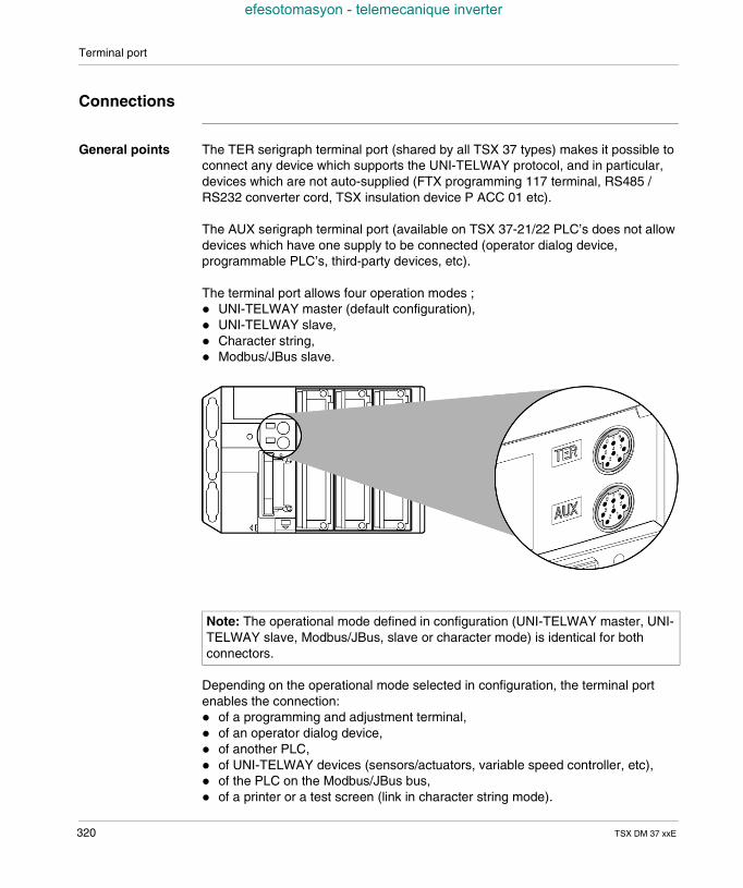
Terminal port
efesotomasyon - telemecanique inverter
Connections
General points The TER serigraph terminal port (shared by all TSX 37 types) makes it possible toconnect any device which supports the UNI-TELWAY protocol, and in particular,devices which are not auto-supplied (FTX programming 117 terminal, RS485 /RS232 converter cord, TSX insulation device P ACC 01 etc).
The AUX serigraph terminal port (available on TSX 37-21/22 PLC’s does not allowdevices which have one supply to be connected (operator dialog device,programmable PLC’s, third-party devices, etc).
The terminal port allows four operation modes ; UNI-TELWAY master (default configuration), UNI-TELWAY slave, Character string, Modbus/JBus slave.
Depending on the operational mode selected in configuration, the terminal portenables the connection: of a programming and adjustment terminal, of an operator dialog device, of another PLC, of UNI-TELWAY devices (sensors/actuators, variable speed controller, etc), of the PLC on the Modbus/JBus bus, of a printer or a test screen (link in character string mode).
Note: The operational mode defined in configuration (UNI-TELWAY master, UNI-TELWAY slave, Modbus/JBus, slave or character mode) is identical for bothconnectors.
320 TSX DM 37 xxE
Terminal port
efesotomasyon - telemecanique inverter
Using an insulation device, reference TSX P ACC 01, doubles the terminal port,which makes it possible to simultaneously connect a programming terminal and aoperator dialog device on a TSX 37-05/08/10 PLC.This device is also required: to connect a PLC type TSX 37 onto :
a UNI-TELWAY link when the distance between the devices is greater than 10meters,
a Modbus/JBus bus, to set a TSX 37 to slave mode. This device is described in the following chapter.
Note: When connecting a TSX 37 PLC slave onto a UNI-TELWAY bus or Modbus/JBus, it is essential to use a TSX P ACC 01.
TSX DM 37 xxE 321
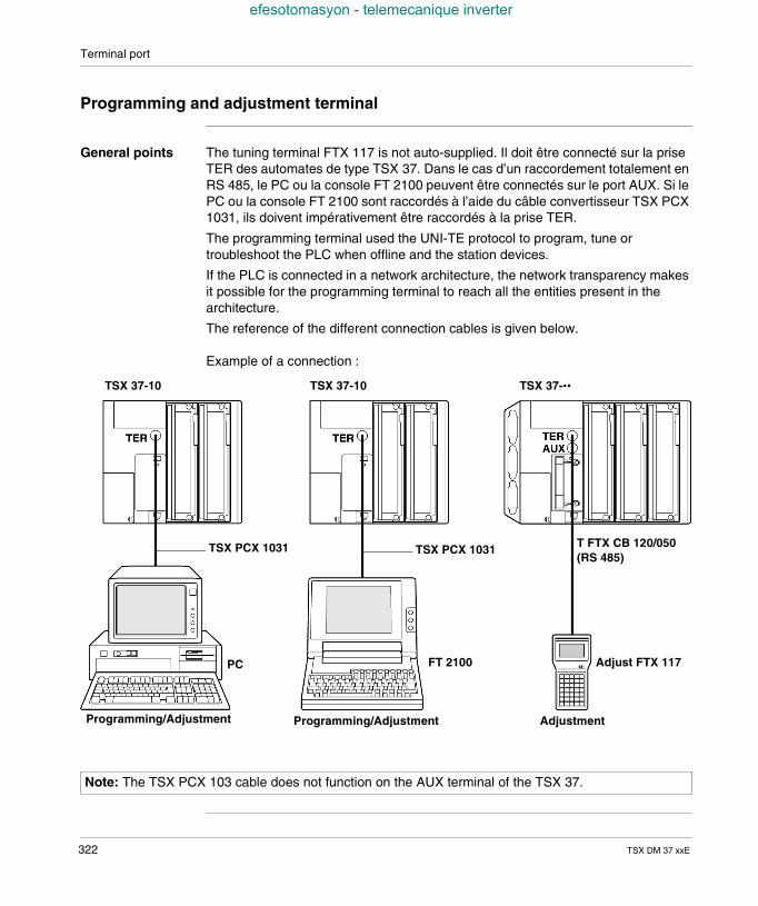
Terminal port
efesotomasyon - telemecanique inverter
Programming and adjustment terminal
General points The tuning terminal FTX 117 is not auto-supplied. Il doit être connecté sur la priseTER des automates de type TSX 37. Dans le cas d’un raccordement totalement enRS 485, le PC ou la console FT 2100 peuvent être connectés sur le port AUX. Si lePC ou la console FT 2100 sont raccordés à l’aide du câble convertisseur TSX PCX1031, ils doivent impérativement être raccordés à la prise TER.
The programming terminal used the UNI-TE protocol to program, tune ortroubleshoot the PLC when offline and the station devices.
If the PLC is connected in a network architecture, the network transparency makesit possible for the programming terminal to reach all the entities present in thearchitecture.
The reference of the different connection cables is given below.
Example of a connection :
Programming/Adjustment
TSX 37-10 TSX 37-10 TSX 37-••
AdjustmentProgramming/Adjustment
TSX PCX 1031
PC FT 2100 Adjust FTX 117
TSX PCX 1031 T FTX CB 120/050(RS 485)
Note: The TSX PCX 103 cable does not function on the AUX terminal of the TSX 37.
322 TSX DM 37 xxE
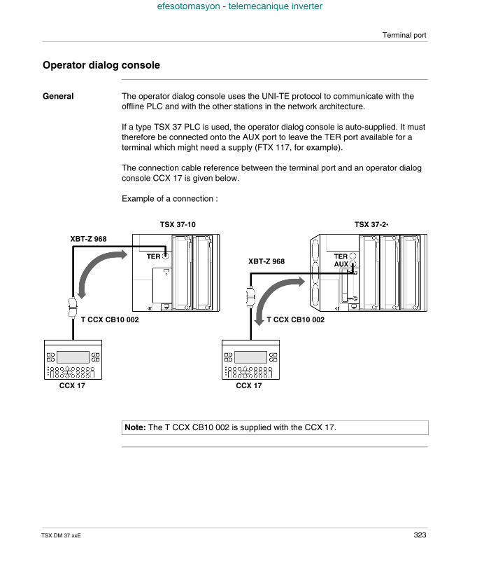
Terminal port
efesotomasyon - telemecanique inverter
Operator dialog console
General The operator dialog console uses the UNI-TE protocol to communicate with theoffline PLC and with the other stations in the network architecture.
If a type TSX 37 PLC is used, the operator dialog console is auto-supplied. It musttherefore be connected onto the AUX port to leave the TER port available for aterminal which might need a supply (FTX 117, for example).
The connection cable reference between the terminal port and an operator dialogconsole CCX 17 is given below.
Example of a connection :
CCX 17
TSX 37-10 TSX 37-2•
T CCX CB10 002
XBT-Z 968
CCX 17
T CCX CB10 002
XBT-Z 968
Note: The T CCX CB10 002 is supplied with the CCX 17.
TSX DM 37 xxE 323
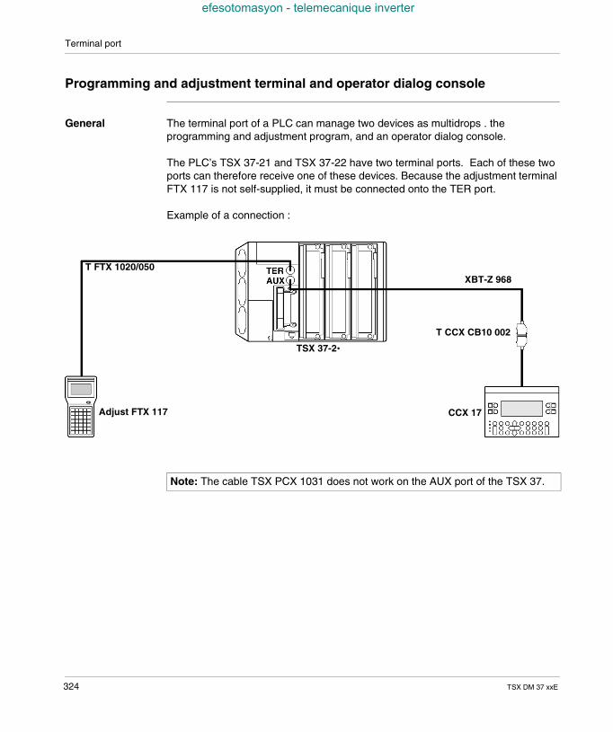
Terminal port
efesotomasyon - telemecanique inverter
Programming and adjustment terminal and operator dialog console
General The terminal port of a PLC can manage two devices as multidrops . theprogramming and adjustment program, and an operator dialog console.
The PLC’s TSX 37-21 and TSX 37-22 have two terminal ports. Each of these twoports can therefore receive one of these devices. Because the adjustment terminalFTX 117 is not self-supplied, it must be connected onto the TER port.
Example of a connection :
TSX 37-2•
Adjust FTX 117
XBT-Z 968
CCX 17
T CCX CB10 002
T FTX 1020/050
Note: The cable TSX PCX 1031 does not work on the AUX port of the TSX 37.
324 TSX DM 37 xxE
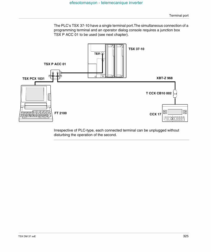
Terminal port
efesotomasyon - telemecanique inverter
The PLC’s TSX 37-10 have a single terminal port.The simultaneous connection of aprogramming terminal and an operator dialog console requires a junction boxTSX P ACC 01 to be used (see next chapter).
Irrespective of PLC-type, each connected terminal can be unplugged withoutdisturbing the operation of the second.
TSX 37-10
FT 2100
XBT-Z 968
CCX 17
T CCX CB10 002
TSX PCX 1031
TSX P ACC 01
TSX DM 37 xxE 325
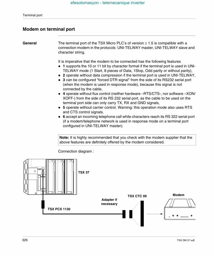
Terminal port
efesotomasyon - telemecanique inverter
Modem on terminal port
General The terminal port of the TSX Micro PLC’s of version ≥ 1.5 is compatible with aconnection modem in the protocols UNI-TELWAY master, UNI-TELWAY slave andcharacter string.
It is imperative that the modem to be connected has the following features 1 supports the 10 or 11 bit by character format if the terminal port is used in UNI-
TELWAY mode (1 Start, 8 pieces of Data, 1Stop, Odd parity or without parity), 2 operate without data compression if the terminal port is used in UNI-TELWAY, 3 can be configured "forced DTR signal" from the side of its RS232 serial port
(when the modem is used in response mode), because this signal is notconnected by the cable,
4 operate without flux control (neither hardware –RTS/CTS-, nor software –XON/XOFF-) from the side of its RS 232 serial port, as the cable to be used on theterminal port side can only carry TX, RX and GND signals,
5 operate without carrier control. Warning: this operation mode also uses RTSand CTS control signals,
6 accept an incoming telephone call while characters reach its RS 322 serial port(if a modem/telephone network is used in response mode on a terminal portconfigured in UNI-TELWAY master).
Connection diagram :
Note: It is highly recommended that you check with the modem supplier that theabove features are definitely offered by the modem considered.
ModemTSX CTC 09
TSX PCX 1130
Adapter ifnecessary
TSX 37
326 TSX DM 37 xxE
Terminal port
efesotomasyon - telemecanique inverter
Example 1 : for a terminal port in UNI-TELWAY mode, connected to a modem/telephone network in response mode, the port must have the above characteristics1 to 6.
Example 2 : for a terminal port in character string mode connected to a modem viaan application-specific line, the port must have the above characteristics from 3 to 5.
Configuration ofthe terminal portin UNI-TELWAYmode
The waiting delay must be between 100 and 250 ms.In master mode, the number of slaves configured must correspond to the realnumber of slaves present on the bus.In slave mode, the number of addresses must correspond to those used.
The TSX Micro PLC’s terminal port is configured from the PL7 Micro or PL7 Juniorsoftware.For further details, please refer to the communication manual TLX DS COM PL7.
TSX DM 37 xxE 327
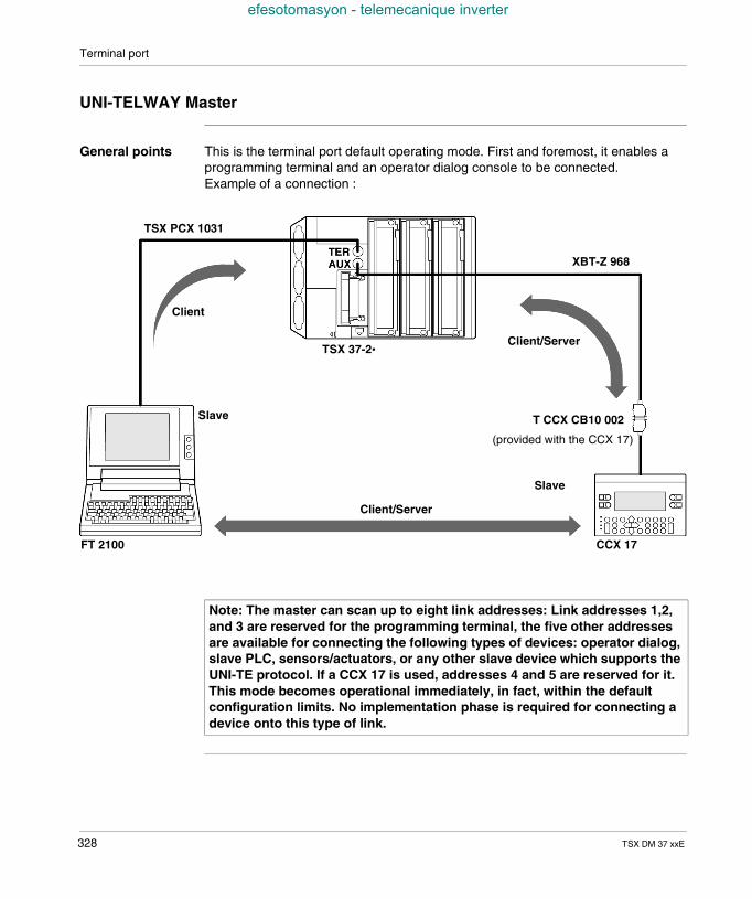
Terminal port
efesotomasyon - telemecanique inverter
UNI-TELWAY Master
General points This is the terminal port default operating mode. First and foremost, it enables aprogramming terminal and an operator dialog console to be connected.Example of a connection :
TSX 37-2•
FT 2100
XBT-Z 968
CCX 17
T CCX CB10 002
TSX PCX 1031
Client/Server
Client/Server
Client
(provided with the CCX 17)
Slave
Slave
Note: The master can scan up to eight link addresses: Link addresses 1,2,and 3 are reserved for the programming terminal, the five other addressesare available for connecting the following types of devices: operator dialog,slave PLC, sensors/actuators, or any other slave device which supports theUNI-TE protocol. If a CCX 17 is used, addresses 4 and 5 are reserved for it.This mode becomes operational immediately, in fact, within the defaultconfiguration limits. No implementation phase is required for connecting adevice onto this type of link.
328 TSX DM 37 xxE
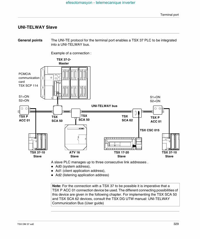
Terminal port
efesotomasyon - telemecanique inverter
UNI-TELWAY Slave
General points The UNI-TE protocol for the terminal port enables a TSX 37 PLC to be integratedinto a UNI-TELWAY bus.
Example of a connection :
A slave PLC manages up to three consecutive link addresses . Ad0 (system address), Ad1 (client application address), Ad2 (listening application address)
TSX 37-2•Master
TSX 37-10Slave
TSXSCA 62
UNI-TELWAY bus
ATV 16Slave
TSX 17-20Slave
TSX 37-10Slave
TSX PACC 01
S1=ONS2=ON
TSXSCA 50
TSXSCA 50
S1=ONS2=ON
TSX PACC 01
TSX CSC 015
PCMCIAcommunicationcardTSX SCP 114
Note: For the connection with a TSX 37 to be possible it is imperative that aTSX P ACC 01 connection device be used. The different connecting possibilities ofthis device are given in the following chapter. For implementing the TSX SCA 50and TSX SCA 62 devices, consult the TSX DG UTW manual: UNI-TELWAYCommunication Bus (User guide)
TSX DM 37 xxE 329
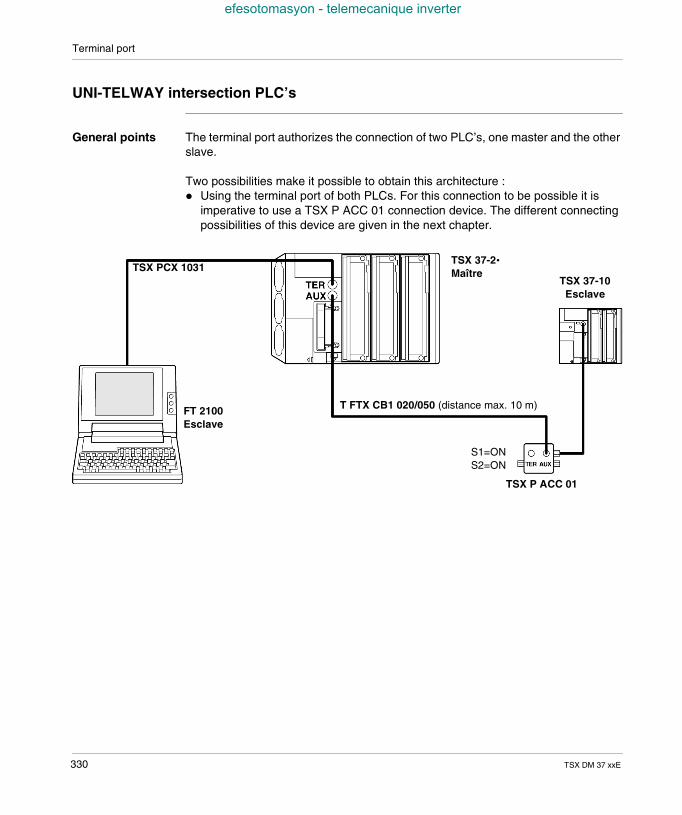
Terminal port
efesotomasyon - telemecanique inverter
UNI-TELWAY intersection PLC’s
General points The terminal port authorizes the connection of two PLC’s, one master and the otherslave.
Two possibilities make it possible to obtain this architecture : Using the terminal port of both PLCs. For this connection to be possible it is
imperative to use a TSX P ACC 01 connection device. The different connectingpossibilities of this device are given in the next chapter.
TSX 37-2•Maître
FT 2100Esclave
TSX P ACC 01
T FTX CB1 020/050 (distance max. 10 m)
TSX 37-10Esclave
S1=ONS2=ON
TSX PCX 1031
330 TSX DM 37 xxE
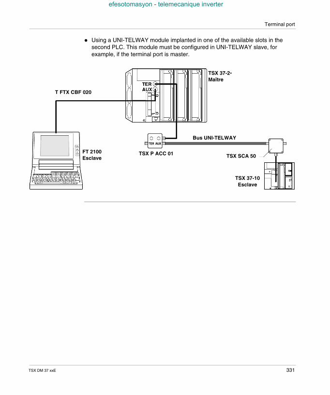
Terminal port
efesotomasyon - telemecanique inverter
Using a UNI-TELWAY module implanted in one of the available slots in thesecond PLC. This module must be configured in UNI-TELWAY slave, forexample, if the terminal port is master.
TSX 37-2•Maître
FT 2100Esclave TSX SCA 50
TSX 37-10Esclave
T FTX CBF 020
Bus UNI-TELWAY
TSX P ACC 01
TSX DM 37 xxE 331
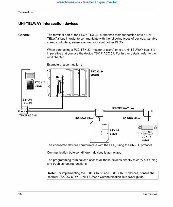
Terminal port
efesotomasyon - telemecanique inverter
UNI-TELWAY intersection devices
General The terminal port of the PLC’s TSX 37, authorizes their connection onto a UNI-TELWAY bus in order to communicate with the following types of devices: variablespeed controllers, sensors/actuators, or with other PLC’s.
When connecting a PLC TSX 37 (master or slave) onto a UNI-TELWAY bus, it isimperative that you use the device TSX P ACC 01. For further details, refer to thenext chapter.
Example of a connection :
The connected devices communicate with the PLC, using the UNI-TE protocol.
Communication between different devices is authorized.
The programming terminal can access all these devices directly to carry out tuningand troubleshooting functions.
TSX 37-2•Master
FTX 117Slave
CCX 17Slave
TSX SCA 50
UNI-TELWAY bus
S1=ONS2=ON
TSX P ACC 01TSX SCA 62
ATV 16Slave
Note: For implementing the TSX SCA 50 and TSX SCA 62 devices, consult themanual TSX DG UTW : UNI-TELWAY Communication Bus (User guide)
332 TSX DM 37 xxE
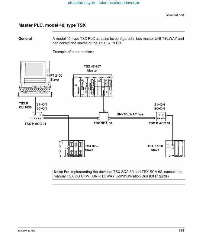
Terminal port
efesotomasyon - telemecanique inverter
Master PLC, model 40, type TSX
General A model 40, type TSX PLC can also be configured in bus master UNI-TELWAY andcan control the slaves of the TSX 37 PLC’s.
Example of a connection :
TSX 37-••Slave
FT 2100Slave
TSX 37-10Slave
TSX SCA 50
UNI-TELWAY bus
S1=ONS0=ON
TSX P ACC 01
TSX 47-107Master
TSX P ACC 01
S1=ONS0=ON
TSX PCU 1030
Note: For implementing the devices: TSX SCA 50 and TSX SCA 62, consult themanual TSX DG UTW : UNI-TELWAY Communication Bus (User guide)
TSX DM 37 xxE 333
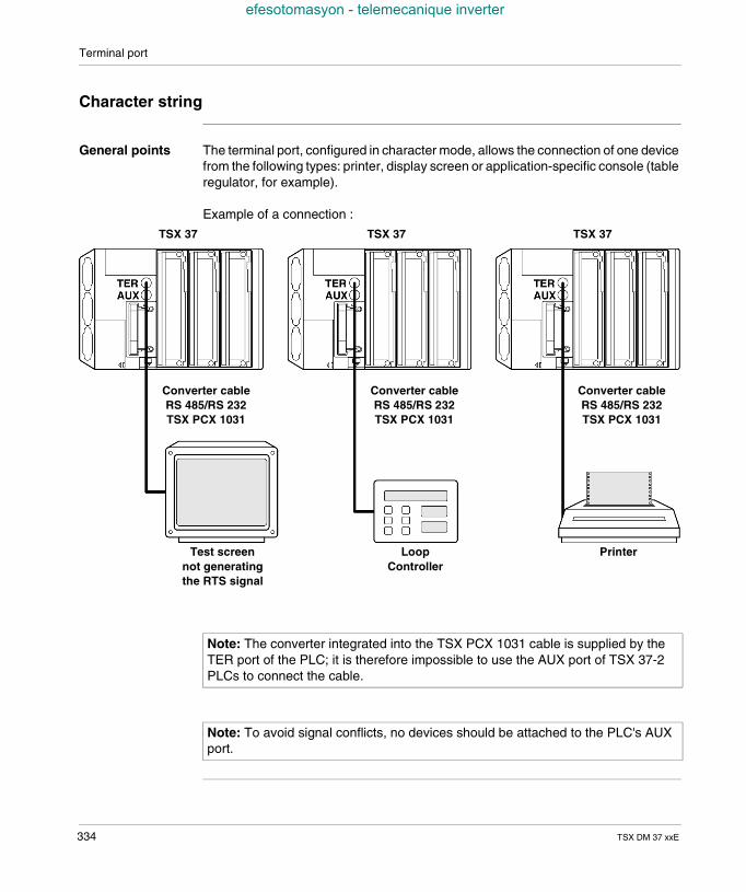
Terminal port
efesotomasyon - telemecanique inverter
Character string
General points The terminal port, configured in character mode, allows the connection of one devicefrom the following types: printer, display screen or application-specific console (tableregulator, for example).
Example of a connection :
Test screennot generatingthe RTS signal
LoopController
TSX 37
Printer
TSX 37 TSX 37
Converter cableRS 485/RS 232TSX PCX 1031
Converter cableRS 485/RS 232TSX PCX 1031
Converter cableRS 485/RS 232TSX PCX 1031
Note: The converter integrated into the TSX PCX 1031 cable is supplied by theTER port of the PLC; it is therefore impossible to use the AUX port of TSX 37-2PLCs to connect the cable.
Note: To avoid signal conflicts, no devices should be attached to the PLC's AUXport.
334 TSX DM 37 xxE
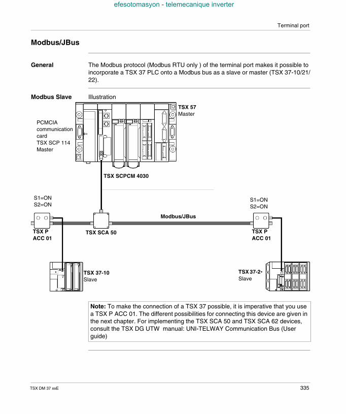
Terminal port
efesotomasyon - telemecanique inverter
Modbus/JBus
General The Modbus protocol (Modbus RTU only ) of the terminal port makes it possible toincorporate a TSX 37 PLC onto a Modbus bus as a slave or master (TSX 37-10/21/22).
Modbus Slave Illustration
TSX 37-2•Slave
PCMCIAcommunicationcardTSX SCP 114Master
TSX 37-10Slave
TSX SCA 50
Modbus/JBus
S1=ONS2=ON
TSX PACC 01
TSX 57Master
TSX PACC 01
S1=ONS2=ON
TSX SCPCM 4030
Note: To make the connection of a TSX 37 possible, it is imperative that you usea TSX P ACC 01. The different possibilities for connecting this device are given inthe next chapter. For implementing the TSX SCA 50 and TSX SCA 62 devices,consult the TSX DG UTW manual: UNI-TELWAY Communication Bus (Userguide)
TSX DM 37 xxE 335
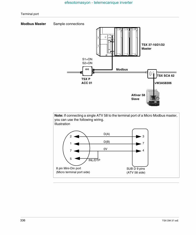
Terminal port
efesotomasyon - telemecanique inverter
Modbus Master Sample connections
Note: If connecting a single ATV 58 to the terminal port of a Micro Modbus master,you can use the following wiring.Illustration
TSX 37-10/21/22Master
Modbus
TSX PACC 01
TSX SCA 62
Altivar 58Slave
S1=ONS2=ON
vW3A58306
3
7
4
2
1
7
5
D(A)
D(B)
0V
INL/DTP
8 pin Mini-Din port(Micro terminal port side)
SUB D 9 pins(ATV 58 side)
336 TSX DM 37 xxE
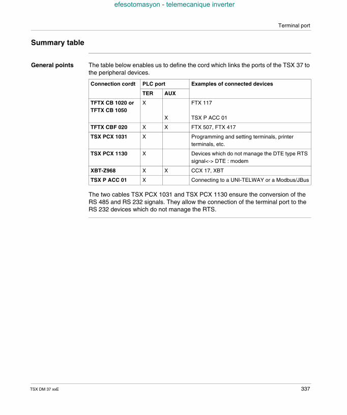
Terminal port
efesotomasyon - telemecanique inverter
Summary table
General points The table below enables us to define the cord which links the ports of the TSX 37 tothe peripheral devices.
The two cables TSX PCX 1031 and TSX PCX 1130 ensure the conversion of theRS 485 and RS 232 signals. They allow the connection of the terminal port to theRS 232 devices which do not manage the RTS.
Connection cordt PLC port Examples of connected devices
TER AUX
TFTX CB 1020 orTFTX CB 1050
X
X
FTX 117
TSX P ACC 01
TFTX CBF 020 X X FTX 507, FTX 417
TSX PCX 1031 X Programming and setting terminals, printerterminals, etc.
TSX PCX 1130 X Devices which do not manage the DTE type RTSsignal<-> DTE : modem
XBT-Z968 X X CCX 17, XBT
TSX P ACC 01 X Connecting to a UNI-TELWAY or a Modbus/JBus
TSX DM 37 xxE 337

Terminal port
efesotomasyon - telemecanique inverter
TSX PCX 1031cable
This multi-function cable enables the PLC to communicate with different devices ofthe RS232 series.The different functions of the series mode are defined according to the position ofthe coil turret accessible via the converter unit.The table below introduces the different functions.
Position ofcoil turret
Function Status ofsignal/DPT
Management of RTSsignal
0 TER MULTI - Connection in point to pointor multi-point mode. UNI-telway masterPLC communication (replace the cablereference TSX PCU 1030 (1)
1 Yes
1 OTHER MULTI - Connection in multi-pointmode. Other types of connection (replacethe cable reference TSX PCD 1030).
0 Yes
2 TER DIRECT - Connection in point to pointmode. Uni-telway master PLCcommunication defined by the PLCconfiguration (replaces the cablereferences TSX PCX 1030 (2) and TSXPCU 1030
1 No
3 OTHER DIRECT - Connection in point topoint mode. Other types of communicationdefined by the PLC configuration (replacesthe cable reference TSX PCX 1030 (3)).
0 No
Legend
(1) Replaces also the cable reference TSX PCU 1031 in multi-point mode.In this case you must update the Uni-telway driver. Depending on youroperating system, the version to use is: Windows 2000/98/ME/XP ≥ V1.0 IE01 Windows NT4 ≥ V1.4 IE9 Windows 95 ≥ V7.8 IE18
(2) Switch in master position
(3) Switch in slave position
338 TSX DM 37 xxE
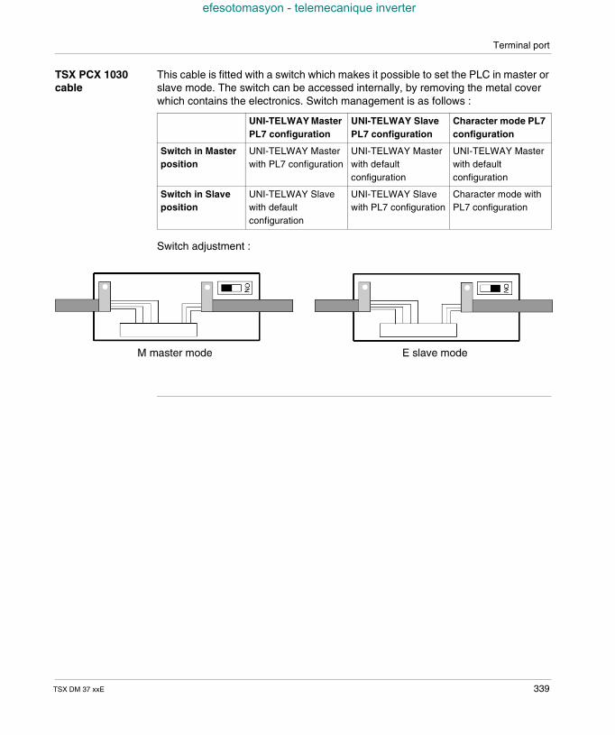
Terminal port
efesotomasyon - telemecanique inverter
TSX PCX 1030cable
This cable is fitted with a switch which makes it possible to set the PLC in master orslave mode. The switch can be accessed internally, by removing the metal coverwhich contains the electronics. Switch management is as follows :
Switch adjustment :
UNI-TELWAY MasterPL7 configuration
UNI-TELWAY SlavePL7 configuration
Character mode PL7configuration
Switch in Masterposition
UNI-TELWAY Masterwith PL7 configuration
UNI-TELWAY Masterwith defaultconfiguration
UNI-TELWAY Masterwith defaultconfiguration
Switch in Slaveposition
UNI-TELWAY Slavewith defaultconfiguration
UNI-TELWAY Slavewith PL7 configuration
Character mode withPL7 configuration
M master mode E slave mode
TSX DM 37 xxE 339
Terminal port
efesotomasyon - telemecanique inverter
31.3 Attachments
Introduction to this Section
Aim of thisSection
This Section describes the features of the terminal port.
What's in thisSection?
This Section contains the following Maps:
Topic Page
Properties of the terminal port 341
Connectors on the TSX 37 PLC 343
340 TSX DM 37 xxE
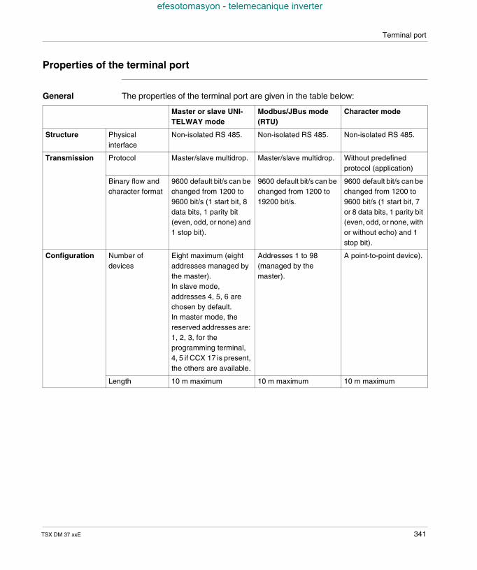
Terminal port
efesotomasyon - telemecanique inverter
Properties of the terminal port
General The properties of the terminal port are given in the table below:
Master or slave UNI-TELWAY mode
Modbus/JBus mode(RTU)
Character mode
Structure Physicalinterface
Non-isolated RS 485. Non-isolated RS 485. Non-isolated RS 485.
Transmission Protocol Master/slave multidrop. Master/slave multidrop. Without predefinedprotocol (application)
Binary flow andcharacter format
9600 default bit/s can bechanged from 1200 to9600 bit/s (1 start bit, 8data bits, 1 parity bit(even, odd, or none) and1 stop bit).
9600 default bit/s can bechanged from 1200 to19200 bit/s.
9600 default bit/s can bechanged from 1200 to9600 bit/s (1 start bit, 7or 8 data bits, 1 parity bit(even, odd, or none, withor without echo) and 1stop bit).
Configuration Number ofdevices
Eight maximum (eightaddresses managed bythe master).In slave mode,addresses 4, 5, 6 arechosen by default.In master mode, thereserved addresses are:1, 2, 3, for theprogramming terminal,4, 5 if CCX 17 is present,the others are available.
Addresses 1 to 98(managed by themaster).
A point-to-point device).
Length 10 m maximum 10 m maximum 10 m maximum
TSX DM 37 xxE 341
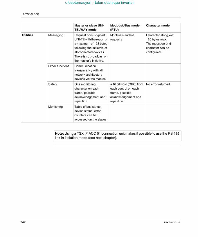
Terminal port
efesotomasyon - telemecanique inverter
Utilities Messaging Request point-to-pointUNI-TE with the report ofa maximum of 128 bytesfollowing the initiative ofall connected devices.There is no broadcast onthe master’s initiative.
Modbus standardrequests
Character string with120 bytes max.The message-endcharacter can beconfigured.
Other functions Communicationtransparency with allnetwork architecturedevices via the master.
Safety One monitoringcharacter on eachframe, possibleacknowledgement andrepetition.
a 16 bit word (CRC) fromeach control on eachframe, possibleacknowledgement andrepetition.
No error returned.
Monitoring Table of bus status,device status, errorcounters can beaccessed on the slaves.
Master or slave UNI-TELWAY mode
Modbus/JBus mode(RTU)
Character mode
Note: Using a TSX P ACC 01 connection unit makes it possible to use the RS 485link in isolation mode (see next chapter).
342 TSX DM 37 xxE
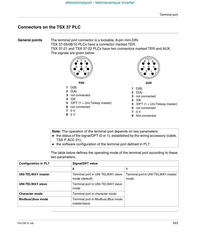
Terminal port
efesotomasyon - telemecanique inverter
Connectors on the TSX 37 PLC
General points The terminal port connector is a lockable, 8-pin mini-DIN.TSX 37-05/08/10 PLCs have a connector marked TER.TSX 37-21 and TSX 37-22 PLCs have two connectors marked TER and AUX.The signals are given below:
The table below defines the operating mode of the terminal port according to thesetwo parameters.
Note: The operation of the terminal port depends on two parameters: the status of the signal/DPT (0 or 1), established by the wiring accessory (cable,
TSX P ACC 01), the software configuration of the terminal port defined in PL7.
1 D(B)2 D(A)3 not connected4 /DE5 /DPT (1 = Uni-Telway master)6 not connected7 0 V8 5 V
1 D(B)2 D(A)3 not connected4 /DE5 /DPT (1 = Uni-Telway master)6 not connected7 0 V8 Not connected
Configuration in PL7 Signal/DPT value
0 1
UNI-TELWAY master Terminal port in UNI-TELWAY slavemode (default)
Terminal port in UNI-TELWAY mastermode
UNI-TELWAY slave Terminal port in UNI-TELWAY slavemode
Character mode Terminal port in character mode
Modbus/Jbus mode Terminal port in Modbus/JBus modemaster/slave
TSX DM 37 xxE 343

Terminal port
efesotomasyon - telemecanique inverter
344 TSX DM 37 xxE
TSX DM 37 xxE
efesotomasyon - telemecanique inverter
32
TSX unit P ACC 01Overview of this chapter
Aim of thischapter
This chapter deals with the TSX unit P ACC 01.
What's in thisChapter?
This Chapter contains the following Sections:
Section Topic Page
32.1 Hardware implementation 346
32.2 Examples of topology 354
345
TSX unit P ACC 01
efesotomasyon - telemecanique inverter
32.1 Hardware implementation
Introduction to this Section
Aim of thisSection
This Section describes in a general, then more detailed way, the unitTSX P ACC 01.
What's in thisSection?
This Section contains the following Maps:
Topic Page
Standard functions 347
External appearance 348
Dimensions and settings 349
Internal view 350
Connection to UNI-TELWAY or Modbus buses 351
Connection to TSX 37 PLCs 352
Switch configuration 353
346 TSX DM 37 xxE
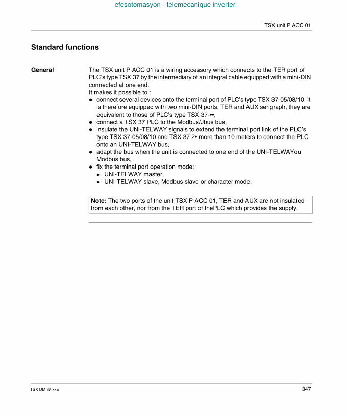
TSX unit P ACC 01
efesotomasyon - telemecanique inverter
Standard functions
General The TSX unit P ACC 01 is a wiring accessory which connects to the TER port ofPLC’s type TSX 37 by the intermediary of an integral cable equipped with a mini-DINconnected at one end.It makes it possible to : connect several devices onto the terminal port of PLC’s type TSX 37-05/08/10. It
is therefore equipped with two mini-DIN ports, TER and AUX serigraph, they areequivalent to those of PLC’s type TSX 37-••,
connect a TSX 37 PLC to the Modbus/Jbus bus, insulate the UNI-TELWAY signals to extend the terminal port link of the PLC’s
type TSX 37-05/08/10 and TSX 37 2• more than 10 meters to connect the PLConto an UNI-TELWAY bus,
adapt the bus when the unit is connected to one end of the UNI-TELWAYouModbus bus,
fix the terminal port operation mode: UNI-TELWAY master, UNI-TELWAY slave, Modbus slave or character mode.
Note: The two ports of the unit TSX P ACC 01, TER and AUX are not insulatedfrom each other, nor from the TER port of thePLC which provides the supply.
TSX DM 37 xxE 347
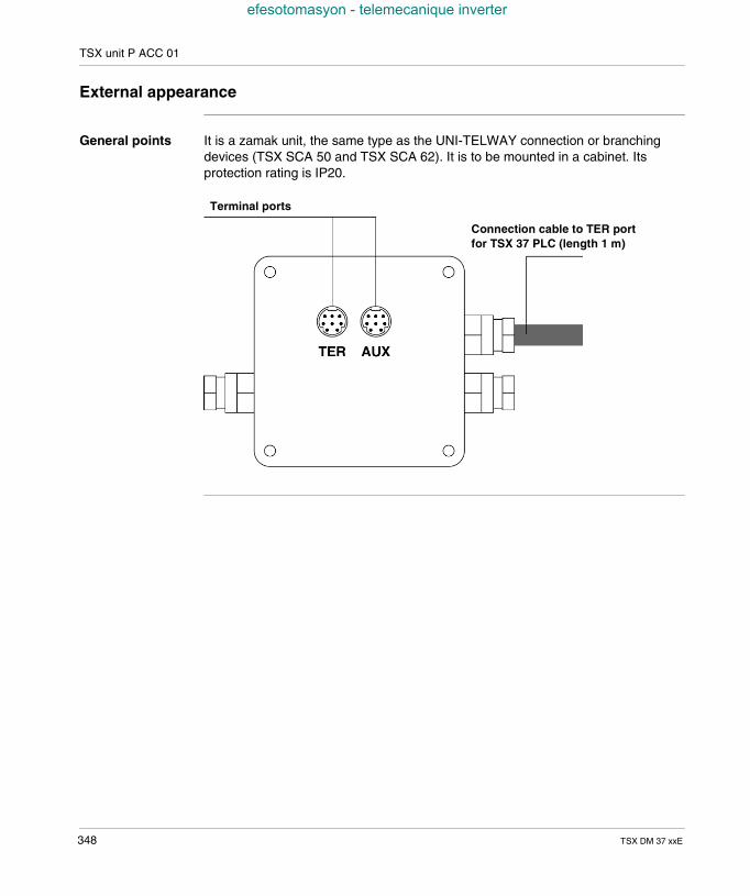
TSX unit P ACC 01
efesotomasyon - telemecanique inverter
External appearance
General points It is a zamak unit, the same type as the UNI-TELWAY connection or branchingdevices (TSX SCA 50 and TSX SCA 62). It is to be mounted in a cabinet. Itsprotection rating is IP20.
Terminal ports
Connection cable to TER portfor TSX 37 PLC (length 1 m)
348 TSX DM 37 xxE
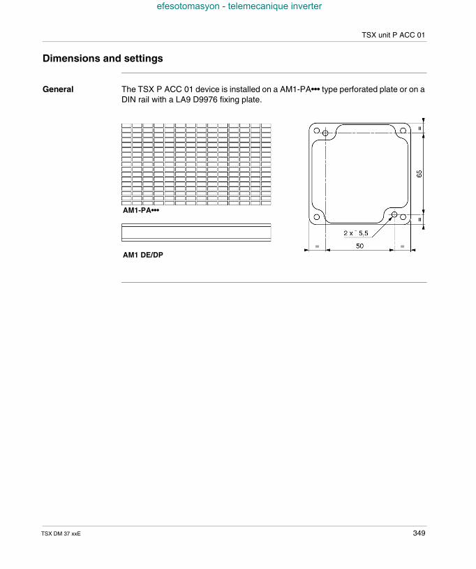
TSX unit P ACC 01
efesotomasyon - telemecanique inverter
Dimensions and settings
General The TSX P ACC 01 device is installed on a AM1-PA••• type perforated plate or on aDIN rail with a LA9 D9976 fixing plate.
AM1-PA•••
AM1 DE/DP
TSX DM 37 xxE 349
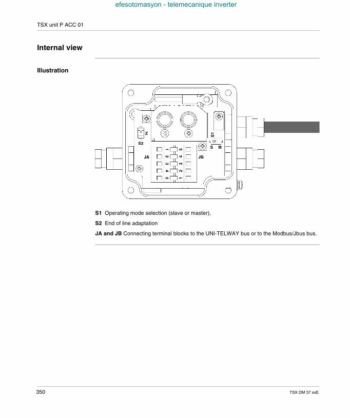
TSX unit P ACC 01
efesotomasyon - telemecanique inverter
Internal view
Illustration
S1 Operating mode selection (slave or master),
S2 End of line adaptation
JA and JB Connecting terminal blocks to the UNI-TELWAY bus or to the Modbus/Jbus bus.
350 TSX DM 37 xxE
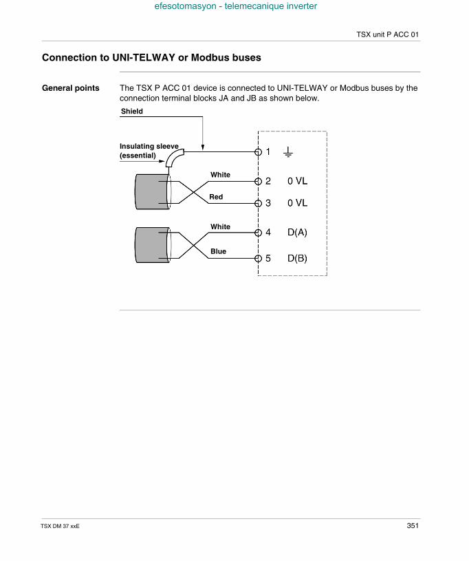
TSX unit P ACC 01
efesotomasyon - telemecanique inverter
Connection to UNI-TELWAY or Modbus buses
General points The TSX P ACC 01 device is connected to UNI-TELWAY or Modbus buses by theconnection terminal blocks JA and JB as shown below.
Shield
White
Red
Blue
White
Insulating sleeve(essential)
TSX DM 37 xxE 351
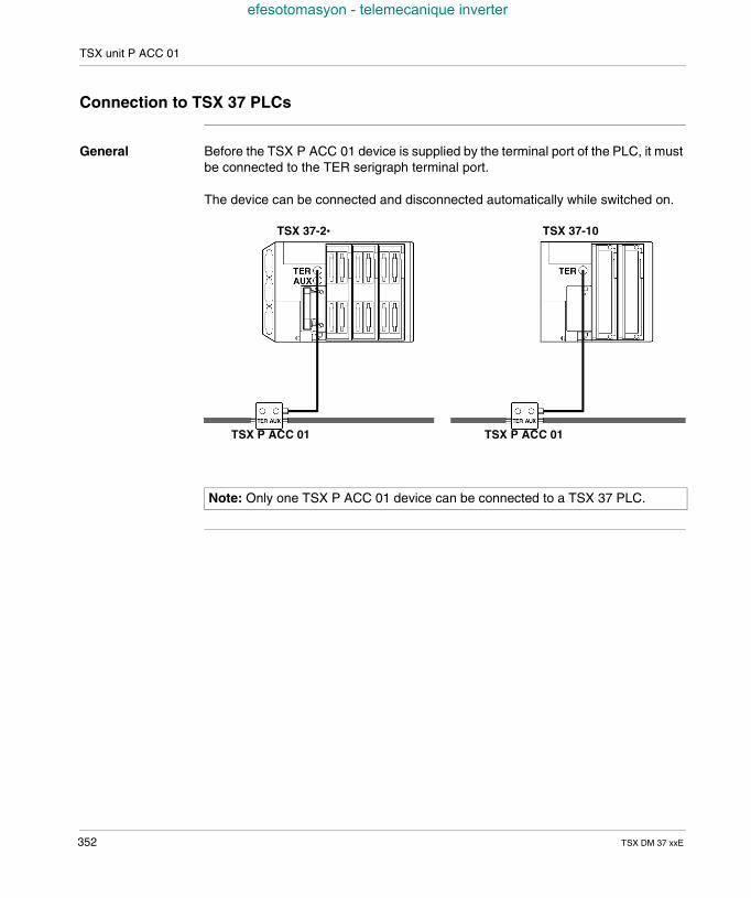
TSX unit P ACC 01
efesotomasyon - telemecanique inverter
Connection to TSX 37 PLCs
General Before the TSX P ACC 01 device is supplied by the terminal port of the PLC, it mustbe connected to the TER serigraph terminal port.
The device can be connected and disconnected automatically while switched on.
Note: Only one TSX P ACC 01 device can be connected to a TSX 37 PLC.
TSX P ACC 01 TSX P ACC 01
TSX 37-10TSX 37-2•
352 TSX DM 37 xxE
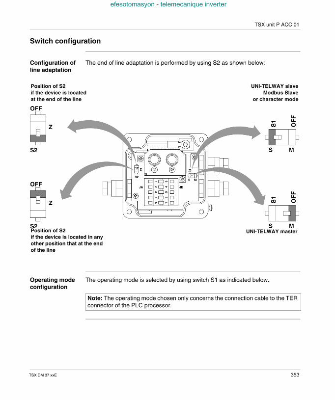
TSX unit P ACC 01
efesotomasyon - telemecanique inverter
Switch configuration
Configuration ofline adaptation
The end of line adaptation is performed by using S2 as shown below:
Operating modeconfiguration
The operating mode is selected by using switch S1 as indicated below.
Position of S2if the device is locatedat the end of the line
Position of S2if the device is located in anyother position that at the endof the line
UNI-TELWAY slaveModbus Slave
or character mode
UNI-TELWAY master
Note: The operating mode chosen only concerns the connection cable to the TERconnector of the PLC processor.
TSX DM 37 xxE 353
TSX unit P ACC 01
efesotomasyon - telemecanique inverter
32.2 Examples of topology
Introduction to this Section
Aim of thisSection
This Section contains different examples of topology.
What's in thisSection?
This Section contains the following Maps:
Topic Page
Connectable devices 355
Master UNI-TELWAY mode 356
Slave UNI-TELWAY mode 357
Modbus/JBus 358
Connection between two PLCs 359
TSX P ACC 01 connectors 360
354 TSX DM 37 xxE
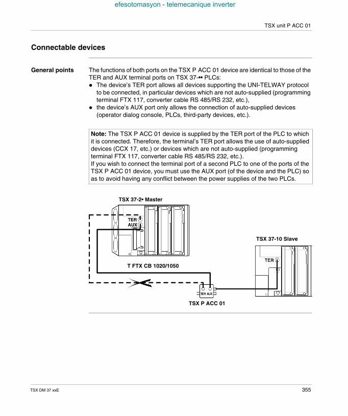
TSX unit P ACC 01
efesotomasyon - telemecanique inverter
Connectable devices
General points The functions of both ports on the TSX P ACC 01 device are identical to those of theTER and AUX terminal ports on TSX 37-•• PLCs: The device’s TER port allows all devices supporting the UNI-TELWAY protocol
to be connected, in particular devices which are not auto-supplied (programmingterminal FTX 117, converter cable RS 485/RS 232, etc.),
the device’s AUX port only allows the connection of auto-supplied devices(operator dialog console, PLCs, third-party devices, etc.).
Note: The TSX P ACC 01 device is supplied by the TER port of the PLC to whichit is connected. Therefore, the terminal’s TER port allows the use of auto-supplieddevices (CCX 17, etc.) or devices which are not auto-supplied (programmingterminal FTX 117, converter cable RS 485/RS 232, etc.).If you wish to connect the terminal port of a second PLC to one of the ports of theTSX P ACC 01 device, you must use the AUX port (of the device and the PLC) soas to avoid having any conflict between the power supplies of the two PLCs.
TSX P ACC 01
TSX 37-2• Master
TSX 37-10 Slave
T FTX CB 1020/1050
TSX DM 37 xxE 355
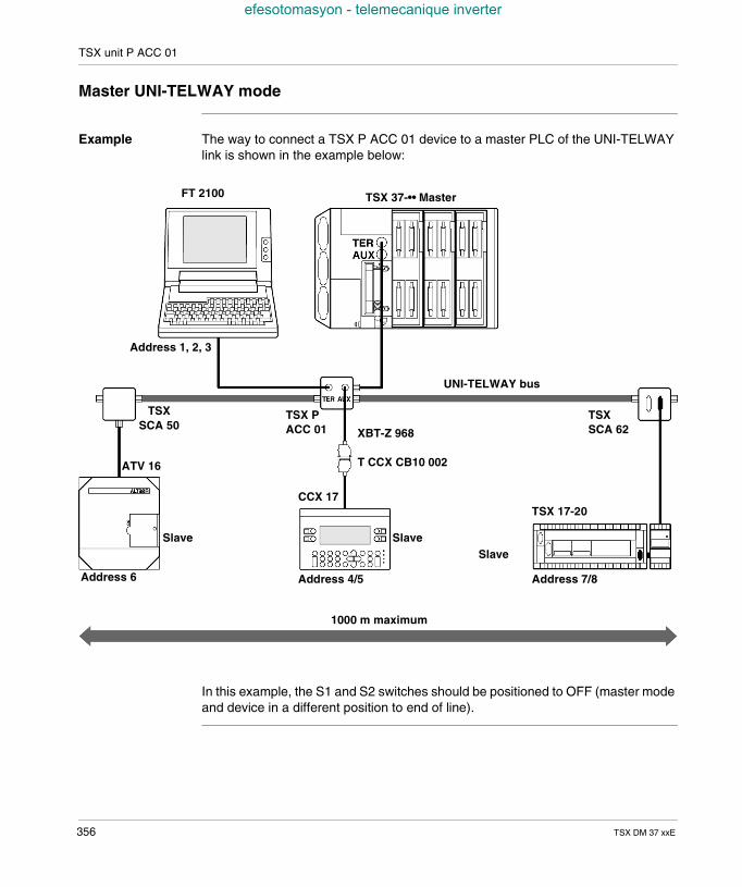
TSX unit P ACC 01
efesotomasyon - telemecanique inverter
Master UNI-TELWAY mode
Example The way to connect a TSX P ACC 01 device to a master PLC of the UNI-TELWAYlink is shown in the example below:
In this example, the S1 and S2 switches should be positioned to OFF (master modeand device in a different position to end of line).
TSX 37-•• Master
TSX 17-20
XBT-Z 968
T CCX CB10 002
TSXSCA 62
UNI-TELWAY bus
Address 6
TSX PACC 01
TSXSCA 50
FT 2100
ATV 16
Address 4/5 Address 7/8
Address 1, 2, 3
1000 m maximum
SlaveSlave
Slave
CCX 17
356 TSX DM 37 xxE
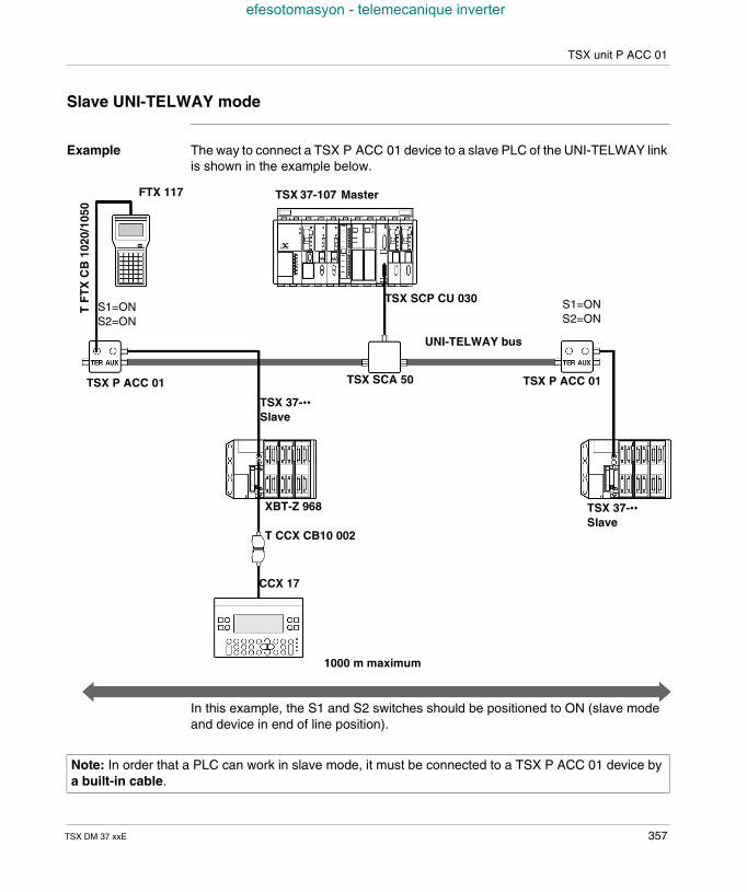
TSX unit P ACC 01
efesotomasyon - telemecanique inverter
Slave UNI-TELWAY mode
Example The way to connect a TSX P ACC 01 device to a slave PLC of the UNI-TELWAY linkis shown in the example below.
In this example, the S1 and S2 switches should be positioned to ON (slave modeand device in end of line position).
TSX 37-••Slave
UNI-TELWAY bus
TSX P ACC 01 TSX SCA 50
FTX 117
XBT-Z 968
T CCX CB10 002
CCX 17
1000 m maximum
TSX P ACC 01
TSX 37-••Slave
S1=ONS2=ON
S1=ONS2=ON
TF
TX
CB
1020
/105
0
TSX SCP CU 030
TSX 37-107 Master
Note: In order that a PLC can work in slave mode, it must be connected to a TSX P ACC 01 device bya built-in cable.
TSX DM 37 xxE 357
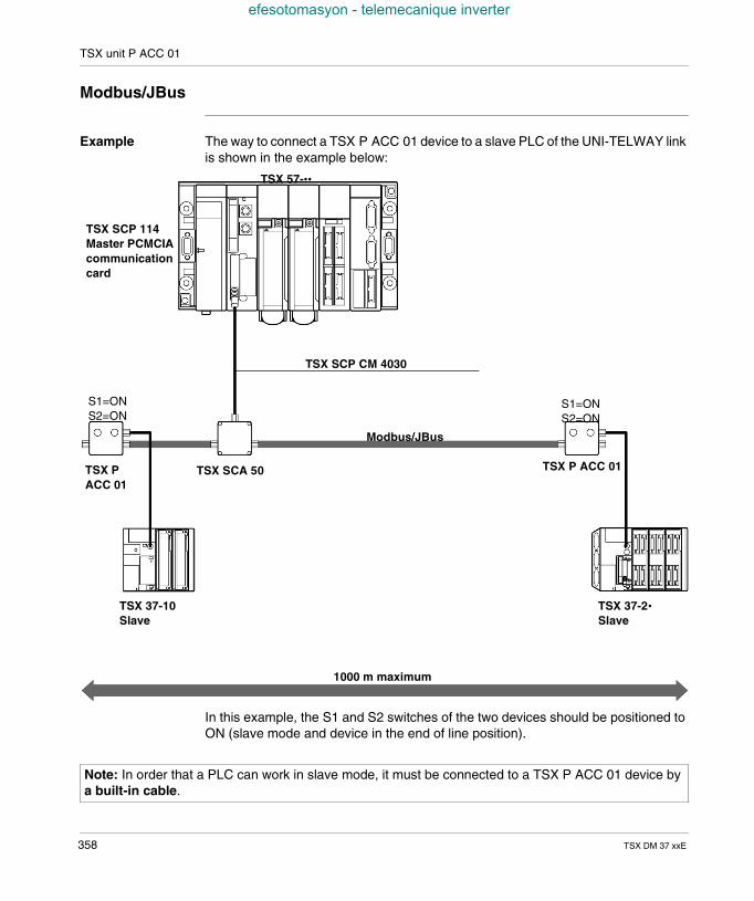
TSX unit P ACC 01
efesotomasyon - telemecanique inverter
Modbus/JBus
Example The way to connect a TSX P ACC 01 device to a slave PLC of the UNI-TELWAY linkis shown in the example below:
In this example, the S1 and S2 switches of the two devices should be positioned toON (slave mode and device in the end of line position).
TSX 37-10Slave
Modbus/JBus
TSX PACC 01
TSX SCA 50
1000 m maximum
TSX P ACC 01
TSX 37-2•Slave
S1=ONS2=ON
S1=ONS2=ON
TSX SCP CM 4030
TSX 57-••
TSX SCP 114Master PCMCIAcommunicationcard
Note: In order that a PLC can work in slave mode, it must be connected to a TSX P ACC 01 device bya built-in cable.
358 TSX DM 37 xxE
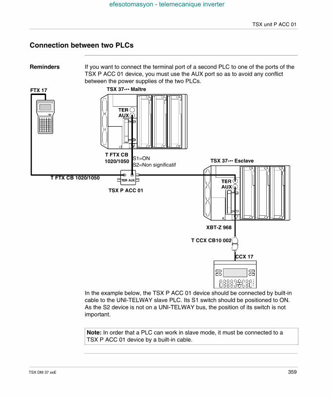
TSX unit P ACC 01
efesotomasyon - telemecanique inverter
Connection between two PLCs
Reminders If you want to connect the terminal port of a second PLC to one of the ports of theTSX P ACC 01 device, you must use the AUX port so as to avoid any conflictbetween the power supplies of the two PLCs.
In the example below, the TSX P ACC 01 device should be connected by built-incable to the UNI-TELWAY slave PLC. Its S1 switch should be positioned to ON.As the S2 device is not on a UNI-TELWAY bus, the position of its switch is notimportant.
TSX 37-•• MaîtreFTX 17
TSX P ACC 01
CCX 17
S1=ONS2=Non significatif
T FTX CB 1020/1050
TSX 37-•• EsclaveT FTX CB1020/1050
XBT-Z 968
T CCX CB10 002
Note: In order that a PLC can work in slave mode, it must be connected to aTSX P ACC 01 device by a built-in cable.
TSX DM 37 xxE 359
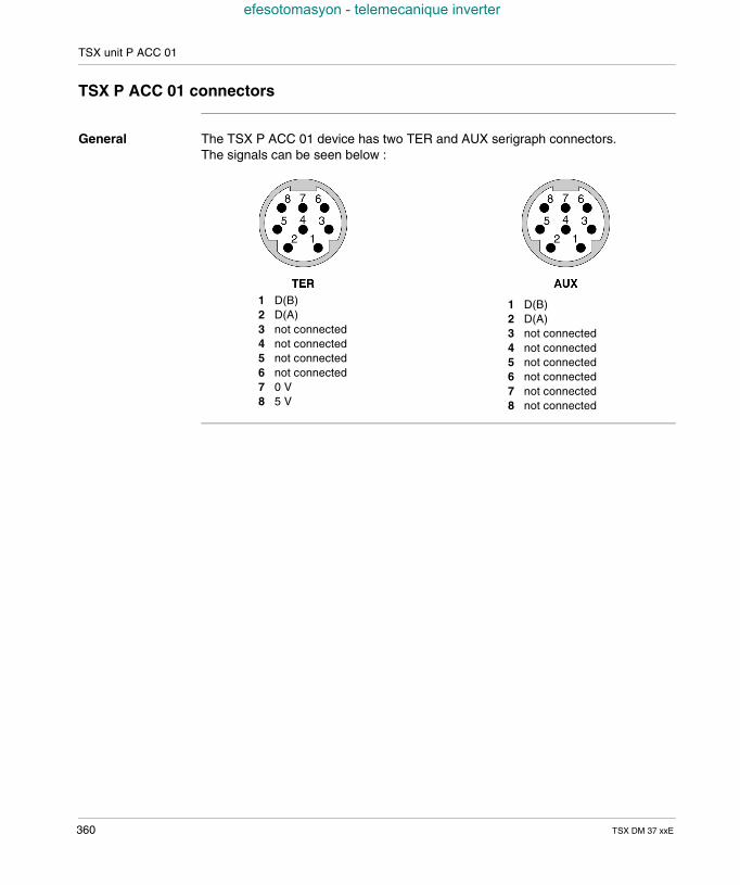
TSX unit P ACC 01
efesotomasyon - telemecanique inverter
TSX P ACC 01 connectors
General The TSX P ACC 01 device has two TER and AUX serigraph connectors.The signals can be seen below :
1 D(B)2 D(A)3 not connected4 not connected5 not connected6 not connected7 0 V8 5 V
1 D(B)2 D(A)3 not connected4 not connected5 not connected6 not connected7 not connected8 not connected
360 TSX DM 37 xxE
CBAIndex
efesotomasyon - telemecanique inverter
Numerics10 kHz up/down counting on channel 11,252, 254, 25510 kHz up/down counting on channels 11and 12, 25110KHz up or down counting, 249500Hz counts on discrete inputs, 232
AAlternating current supply, 72Analog input features, 207Analog inputs/outputs
local, 25remote, 27
Analog output feature, 208
BBlocking faults, 195Built in 10KHz counting function, 233Built in analog connection with insulated ornon-insulated sensors, 213Built in communication
connections, 320Built-in analog
functions, 205Built-in analog connection with TELEFAST,211
TSX DM 37 xxF
CChanging the battery on the PCMCIA card,114Changing the battery on the TSX 37, 110Channel address settings, 41Character mode, 34Character string, 334Communication, 32
character string, 317Modbus/JBus, 318UNI-TELWAY master/slave, 316with a terminal, 314with an operator dialog console, 315
Connecting an encoder with a TSX TAP S1505 accessory, 305Connecting an encoder with a TSX TAP S1524 accessory, 306Connecting an incremental encoder onchannel 11, 279Connecting analog output and externalsliders, 214Connecting counting sensors (DDP) onchannel 11 and 12, 285Connecting PLCs supplied with alternatingcurrent, 122Connecting PLCs supplied with directcurrent, 126Connecting several supplied PLCs, 125Connecting supplies and sensors on channel11, 286Connecting supply and preset sensor, 284Connecting supply and sensors on channel
361
Index
efesotomasyon - telemecanique inverter
12, 287Connecting variable speed controller, 215Connection rules, 121Connection to UNI-TELWAY or Modbusbuses, 351Connectors on the TSX 37 PLC, 343Continuous floating network, 129, 131Counting channel, 28Counting signals on the TELEFAST screwterminal block, 294CPU Faults, 197
DDimensions of the TSX 37 PLC, 100Direct connection of the analog interface,210Direct current supply, 73Discrete inputs/outputs
remote, 22safety, 24
Display64 channel modules, 156faulty inputs/outputs, 159input/output bits of each slave, 164inputs/outputs on the AS-i bus, 161internal bit status, 181introduction, 150local inputs/outputs, 154PLC status, 152presence of the slaves on the AS-i bus,162remote inputs/outputs on the TSX 07,183sequencing, 158
Display in binary mode, 178Display in hexadecimal mode, 176Down counting function, general, 236
EExtension assembly, 104
FFIPIO, 37
362
FIPWAY, 36
GGround connection
of the PLC, 118grounding
the modules, 119
IImplementing 10KHZ upcounter
basic configuration, 272Implementing 10kHz upcounter
characteristics, 274general rules for implementation, 288type of sensors which can be used, 273
Implementing up counter on discrete inputGeneral implementation rules, 270
Implementing up counting in discrete inputtypes of sensor which can be used, 262
Implementing up counting on discrete inputbasic configuration, 260
Implementing up counting on discrete inputsprinciple for connecting supplies andsensors, 264
Incrementation of the slave number, 166Inserting a module, 106Internal memory, 76
LLocal discrete inputs/outputs
in the rack, 21
MMaster PLC, model 40, type TSX, 333Matching TELEFAST terminal blocks/15-pinSUB-D connector, 296Matching TELEFAST/HE10 connector, 300Memory cards
application + files, 80Standard and Backup, 79
Mini extension rack, 81
TSXDM37xxF
Index
efesotomasyon - telemecanique inverter
Modbus, 35Modbus Plus, 39Modbus/JBus, 335Modem link, 38Modem on terminal port, 326Mounting onto a DIN profile, 102Mounting the PLC onto a board or panel, 103Mounting the TSX TAP S15 05/24, 303Mounting/removing the memory card, 112
NNon-blocking faults, 193
OOffset switch
AS-i module, 167Display block, 167
Operator dialog console, 323Overview of micro communication, 310
PPCMCIA memory extension cards, 77Performances, 85Pin configuration of the 15-pin SUB-D(channels 11 and 12) connectors, 276PLC mounting/fixing, 101PLC/encoder connection, 281Preset on reference point short cam, 257Programming and adjustment terminal, 322Programming and adjustment terminal andoperator dialog console, 324Properties of the terminal port, 341Protection treatment for TSX Micro PLCs, 90
RRemoving a module, 108Researching the errors, 192Rules of installation, 98
TSX DM 37 xxF
SScrew tightening torque, 116Standards, 88Supply connections, 120Supply control, 132
TTELEFAST 2
ABE-7CPA01 connection base, 292TELEFAST 2 connection base, 298TELEFAST internal wiring, 218TSX 37-05
characteristics, 49display, 50introduction, 46physical description, 48
TSX 37-08characteristics, 55display, 56introduction, 52physical description, 54
TSX 37-10characteristics, 61description, 60display, 62introduction, 58
TSX 37-21/22characteristics, 68description, 66display, 70introduction, 64
TSX ACZ 03 moduleat a glance, 220
TSX ACZ modulefunction selection, 227implementation, 224standard functions, 222
TSX Micro PLCs, 17
363
Index
efesotomasyon - telemecanique inverter
TSX P ACC 01connectable devices, 355connection between two PLCs, 359connection to TSX 37 PLCs, 352connectors, 360dimensions and settings, 349external appearance, 348internal view, 350master UNI-TELWAY mode, 356Modbus/JBus, 358slave UNI-TELWAY mode, 357standard functions, 347switch configuration, 353
TSX TAP S15••, 301
UUNI-TELWAY, 33UNI-TELWAY intersection devices, 332UNI-TELWAY intersection PLC’s, 330UNI-TELWAY Master, 328UNI-TELWAY Slave, 329Up counting function, general, 237Up or down counting on 500 Hz discreteinputs, 241Up/down counting function general, 238Up/down counting on 500Hz discrete inputs,243
VVentilation module
catalog, 139characteristics, 146connections, 144dimensions, 140introduction, 136mounting, 141physical introduction, 138rules for installation, 143
WWiring the ALTIVAR 16, 216Word %SW67, 171Word %SW68, 173
364
Word %SW69, 175WORD mode, 170
TSXDM37xxF


