TT500 Wiring Loom Fitting Guide Skill level: Thank you for purchasing our TT500 wiring kit. The kit is intended as a simple to fit electrical system that will provide a good supply for road legal lights that you can ride at night by! We take the guess work out of the wiring and provide an electrical system well proven to work. However it should be noted that adding lighting to a vehicle that originally came with none is going to require engineering skill from the person doing the work. If you get stuck, we recommend using lights intended for the XT500 as they well suit the TT and are readily available. Note the lights work on AC so standard filament bulbs are the only sort that can be used. The person doing the work is responsible for ensuring that modifications do not impede other controls or the safe operation of the motorcycle, also that work is carried out to your country’s regulations for vehicle lighting & electrical systems. Using the XT500 as a reference for where and how to mount parts & cable routing guides is recommended. 1. Start at the front of the bike. The front end of the loom has multiple wires (the rear has only 3). It can be placed between the font mudguard and the lower steering yolk (triple clamp). The horn can be mounted here too. 2. Run the loom rearwards down the spine of the frame. Ensure it does not foul the steering or other cables. Keep the loom well away from any exhaust parts.
Transcript
�
TT500 Wiring Loom Fitting Guide
Skill level: �
Thank you for purchasing our TT500 wiring kit. The kit is intended as a simple to fit electrical system that will provide a good supply for road legal lights that you can ride at night by! We take the guess work out of the wiring and provide an electrical system well proven to work. However it should be noted that adding lighting to a vehicle that originally came with none is going to require engineering skill from the person doing the work. If you get stuck, we recommend using lights intended for the XT500 as they well suit the TT and are readily available. Note the lights work on AC so standard filament bulbs are the only sort that can be used. The person doing the work is responsible for ensuring that modifications do not impede other controls or the safe operation of the motorcycle, also that work is carried out to your country’s regulations for vehicle lighting & electrical systems. Using the XT500 as a reference for where and how to mount parts & cable routing guides is recommended.
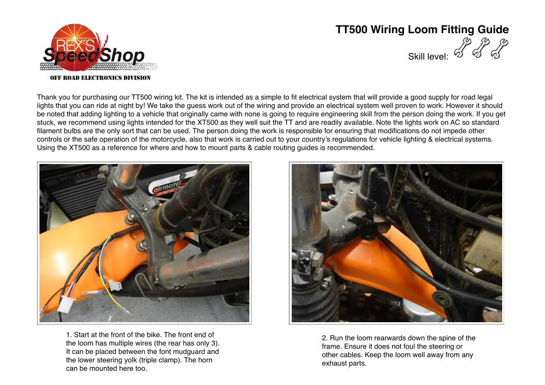
1. Start at the front of the bike. The front end of the loom has multiple wires (the rear has only 3). It can be placed between the font mudguard and the lower steering yolk (triple clamp). The horn can be mounted here too.
2. Run the loom rearwards down the spine of the frame. Ensure it does not foul the steering or other cables. Keep the loom well away from any exhaust parts.
�
TT500 Wiring Loom Fitting Guide
Skill level: �
3. Ensure the loom runs on the inside of the frame at this point as shown.
4. And carry on to the rear lamp position over the rear mudguard, keeping it away from the exhaust.
7. Fit the regulator. The rear air filter mounting is suitable point. This must be bolted. 8. Cable tie the condenser to the wiring loom.
Also run the rear brake light wires under the air filter to the rear brake.
5. Earth the wiring loom and fit the engine earth jumper at the HT coil mounting
6. Fit the earth jumper to the engine at the rocker box, the other end goes to the HT earth.
TT500 Wiring Loom Fitting Guide
Skill level: �
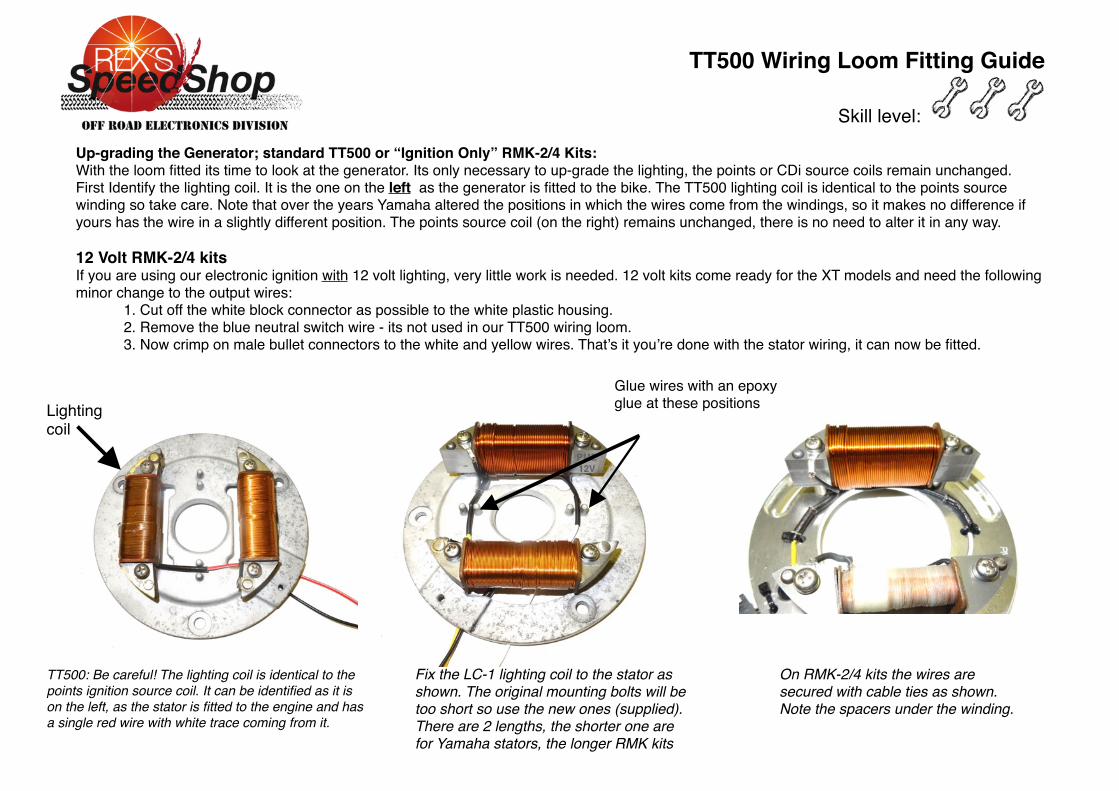
Up-grading the Generator; standard TT500 or “Ignition Only” RMK-2/4 Kits:With the loom fitted its time to look at the generator. Its only necessary to up-grade the lighting, the points or CDi source coils remain unchanged.First Identify the lighting coil. It is the one on the left as the generator is fitted to the bike. The TT500 lighting coil is identical to the points source winding so take care. Note that over the years Yamaha altered the positions in which the wires come from the windings, so it makes no difference if yours has the wire in a slightly different position. The points source coil (on the right) remains unchanged, there is no need to alter it in any way.
12 Volt RMK-2/4 kitsIf you are using our electronic ignition with 12 volt lighting, very little work is needed. 12 volt kits come ready for the XT models and need the following minor change to the output wires:
1. Cut off the white block connector as possible to the white plastic housing. 2. Remove the blue neutral switch wire - its not used in our TT500 wiring loom.3. Now crimp on male bullet connectors to the white and yellow wires. That’s it you’re done with the stator wiring, it can now be fitted.
TT500: Be careful! The lighting coil is identical to the points ignition source coil. It can be identified as it is on the left, as the stator is fitted to the engine and has a single red wire with white trace coming from it.
Lighting coil
Glue wires with an epoxy glue at these positions
On RMK-2/4 kits the wires are secured with cable ties as shown. Note the spacers under the winding.
Fix the LC-1 lighting coil to the stator as shown. The original mounting bolts will be too short so use the new ones (supplied). There are 2 lengths, the shorter one are for Yamaha stators, the longer RMK kits
TT500 Wiring Loom Fitting Guide
Skill level: �
Final Actions
Fit the handle bar switch to the left hand side. Note it is intended for 7/8” bars. If you have fatter ones you’ll need to engineer a solution.
Run the cable under the bars and through the yokes (triple clamps) to enter the head lamp. Secure to the bars with the cable ties (supplied)
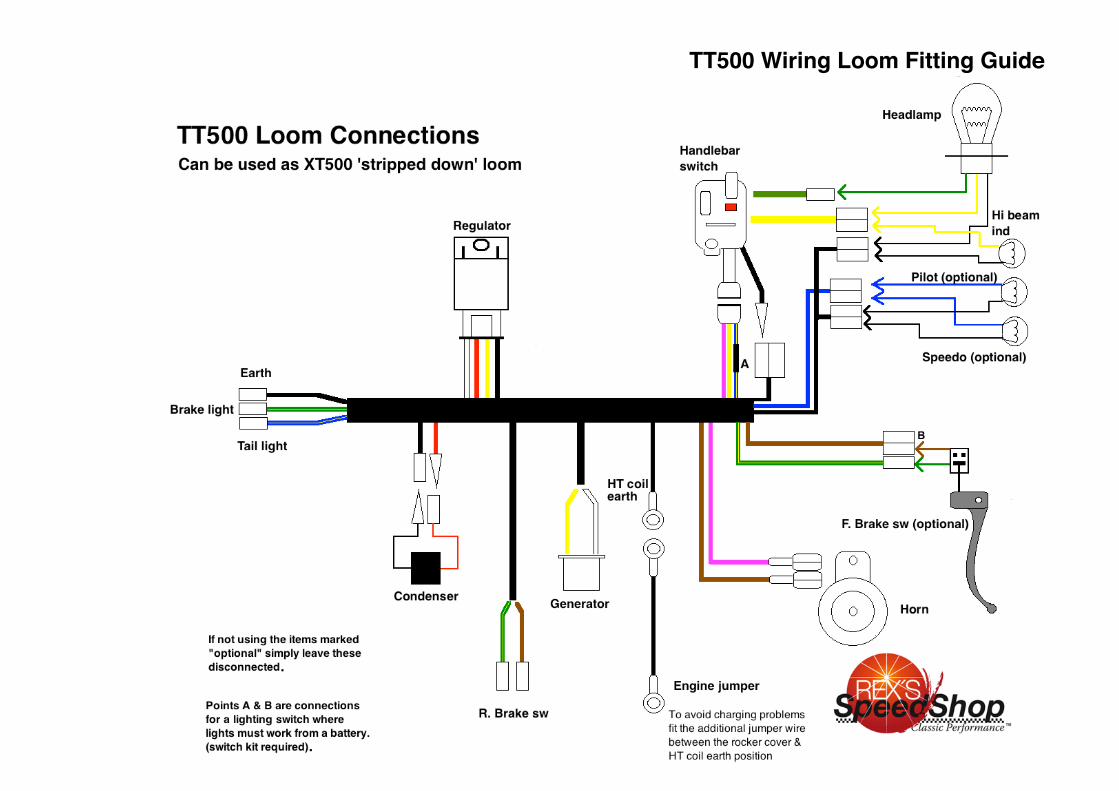
The switch has a dedicated block connector plus single bullet connectors. The yellow wire is high beam, the green low beam.
You should now be in a position to start fitting lamps and a horn.
Items that you don’t want to use, for example a front brake light switch can simply be left un connected. We have designed the loom so it is safe to do this.
Switch loom routing guide:
Once you have fitted all the lamps and accessories you want, double check your connections.
Check the chargingWith the condenser connected measure the voltage. This will be DC and should be between 13.8 and 15 volts.
You must always have the condenser in circuit, or a battery. The regulator/rectifier will be damaged if it not connected or even disconnected for a split second with the engine running.
Because there is so little being used and with no battery to charge the system does charge slightly higher than you’d expect on a road bike.
Fitting a battery.The system is designed to run with no battery, however you may use a sealed AGM type battery, either a motobatt MB3U or our small battery (P/N DT12V-Batt). Batteries do not like engine vibration so you must construct a vibration isolated mount. We supply a wiring kit (P/N WL44) to connect a battery to the new loom.
Connecting an H4 Euro headlamp socket to Yamaha loom (Double sockets must be replaced with single male bullets)