Sergei Slussarenko,1,∗ Anatoli Murauski,2 Tao Du,2
Vladimir Chigrinov,2 Lorenzo Marrucci,1,3 and Enrico Santamato1
1Dipartimento di Scienze Fisiche, Universita di Napoli “Federico II”, ComplessoUniversitario di Monte S. Angelo, 80126 Napoli, Italy
2Hong Kong University of Science and Technology, Clear Water Bay, Kowloon, Hong Kong3CNR-SPIN, Complesso Universitario di Monte S. Angelo, I-80126 Napoli, Italy
Abstract: Using a photoalignment technique with a sulphonic azo-dyeas the surfactant aligning material, we fabricated electrically tunable liquidcrystal q-plates with topological charge 0.5, 1.5 and 3 for generating opticalvortex beams with definite orbital angular momentum (OAM) 1,3 and 6per photon (in units of h), respectively. We carried out several tests onour q-plates, including OAM tomography, finding excellent performances.These devices can have useful applications in general and quantum optics.
References and links1. L. Allen, M. W. Beijersbergen, R. J. C. Spreeuw, and J. P. Woerdman, “Orbital angular momentum of light and
the transformation of Laguerre-Gaussian laser modes,” Phys. Rev. A 45, 8185–8189 (1992).2. S. Franke-Arnold, L. Allen, and M. J. Padgett, “Advances in optical angular momentum,” Laser Photon. Rev. 2,
299–313 (2008).3. A. Jesacher, S. Furhapter, S. Bernet, and M. Ritsch-Marte, “Shadow effects in spiral phase contrast microscopy,”
Phys. Rev. Lett. 94, 233902 (2005).4. G. Gibson, J. Courtial, M. J. Padgett, M. Vasnetsov, V. Pasko, S. M. Barnett, and S. Franke-Arnold, “Free-space
information transfer using light beams carrying orbital angular momentum,” Opt. Express 12, 5448–5456 (2004).5. A. Mair, A. Vaziri, G. Welhs, and A. Zeilinger, “Entanglement of the angular momentum states of photons,”
Nature 412, 313–315 (2001).6. J. T. Barreiro, N. K. Langford, N. A. Peters, and P. G. Kwiat, “Generation of hyperentangled photon pairs,” Phys.
Rev. Lett. 95, 260501 (2005).7. G. Molina-Terriza, J. P. Torres, and L. Torner, “Twisted photons,” Nat. Phys. 3, 305–310 (2007).8. L. Aolita and S. P. Walborn, “Quantum communication without alignment using multiple-qubit single-photon
states,” Phys. Rev. Lett. 98, 100501 (2007).9. M. W. Beijersbergen, R. P. C. Coerwinkel, M. Kristensen, and J. P. Woerdman, “Helical-wavefront laser beams
produced with a spiral phaseplate,” Opt. Commun. 112, 321–327 (1994).10. M. W. Beijersbergen, L. Allen, H. van der Veen, and J. P. Woerdman, “Astigmatic laser mode converters and
transfer of orbital angular momentum,” Opt. Commun. 96, 123–132 (1993).11. V. Y. Bazheov, M. S. Soskin, and M. V. Vasnetsov, “Screw dislocations in light wavefronts,” J. Mod. Opt. 39,
985–990 (1992).12. Y. Igasaki, F. Li, N. Yoshida, H. Toyoda, T. Inoue, N. Mukohzaka, Y. Kobayashi, and T. Hara, “High efficiency
electrically-addressable phase-only spatial light modulator,” Opt. Rev. 6, 339–344 (1999).13. L. Marrucci, C. Manzo, and D. Paparo, “Optical spin-to-orbital angular momentum conversion in inhomogeneous
anisotropic media,” Phys. Rev. Lett. 96, 163905 (2006).14. L. Marrucci, C. Manzo, and D. Paparo, “Pancharatnam-Berry phase optical elements for wavefront shaping in
the visible domain: switchable helical modes generation,” Appl. Phys. Lett. 88, 221102 (2006).15. E. Karimi, B. Piccirillo, E. Nagali, L. Marrucci, and E. Santamato, “Efficient generation and sorting of orbital
angular momentum eigenmodes of light by thermally tuned q-plates,” Appl. Phys. Lett. 94, 231124 (2009).
#136999 - $15.00 USD Received 22 Oct 2010; revised 10 Dec 2010; accepted 13 Dec 2010; published 16 Feb 2011(C) 2011 OSA 28 February 2011 / Vol. 19, No. 5 / OPTICS EXPRESS 4085
16. B. Piccirillo, V. DAmbrosio, S. Slussarenko, L. Marrucci, and E. Santamato, “Photon spin-to-orbital angularmomentum conversion via an electrically tunable q-plate,” Appl. Phys. Lett. arXiv:1010.4473 (in press).
17. E. Karimi, S. Slussarenko, B. Piccirillo, L. Marrucci, and E. Santamato, “Polarization-controlled evolution oflight transverse modes and associated pancharatnam geometric phase in orbital angular momentum,” Phys.Rev. A 81, 053813 (2010).
18. E. Nagali, L. Sansoni, F. Sciarrino, F. De Martini, L. Marrucci, B. Piccirillo, E. Karimi, and E. Santamato,“Optimal quantum cloning of orbital angular momentum photon qubits through hong-ou-mandel coalescence,”Nat. Photon. 3, 720–723 (2009).
19. S. Nersisyan, N. Tabiryan, D. M. Steeves, and B. R. Kimball, “Fabrication of liquid crystal polymer axial wave-plates for uv-ir wavelengths,” Opt. Express 17, 11926–11934 (2009).
20. P. G. de Gennes, The Physics of Liquid Crystals (Oxford University Press, Oxford, 1974).21. The strong anchoring at both the sample walls prevents the decay of the otherwise unstable disclination lines
with integer q.22. V. G. Chigrinov, V. M. Kozenkov, and H.-S. Kwok, Photoalignment of Liquid Crystalline Materials: Physics and
Applications (Wiley Publishing, 2008).23. D. F. V. James, P. G. Kwiat, W. J. Munro, and A. G. White, “Measurement of qubits,” Phys. Rev. A 64, 052312
(2001).24. The fidelity of the measured state |ψ〉 with respect to the expected state |ψ0〉 is usually defined as 〈ψ|ψ0〉2.25. B. Jack, J. Leach, H. Ritsch, S. M. Barnett, M. J. Padgett, and S. Franke-Arnold, “Precise quantum tomography
of photon pairs with entangled orbital angular momentum,” N. J. Phys. 11, 103024 (2009).26. E. Nagali, F. Sciarrino, F. De Martini, L. Marrucci, B. Piccirillo, E. Karimi, and E. Santamato, “Quantum infor-
mation transfer from spin to orbital angular momentum of photons,” Phys. Rev. Lett. 103, 013601 (2009).
1. Introduction
A light beam has two “rotational” degrees of freedom: spin angular momentum (SAM) andorbital angular momentum (OAM). The first is associated to the polarization of the transverseelectric field and may take the values s = ±h per photon, that correspond to circular left andright polarization, respectively. OAM is associated to the phase structure of the complex electricfield and paraxial beams with a helical phase front defined by the factor of exp(i�ϕ) carry adefinite amount of OAM per photon equal to �h, where � can take any integer value [1, 2].In last years, beams carrying OAM have received an increased attention in classical [3, 4] andquantum optics [5–8]. Till now, few methods of OAM-carrying beam generation were proposed,namely spiral phase plates [9], astigmatic lens converters [1, 10] and computer generated forkholograms (CGH) [11] in conjunction with spatial light modulators (SLMs) [5, 12]. All thesemethods have in terms of efficiency, working speed and stability or have specific requirementsfor the input light state.
Recently, a novel device based on liquid crystal (LC) technology, able to generate and ma-nipulate the OAM was introduced [13, 14]. This device, called “q-plate” (QP) is essentially abirefringent wave plate with inhomogeneous patterned distribution of the local optical axis inthe transverse plane. The pattern of the optical axis distribution is defined by a semi-integertopological charge “q”. When a circularly polarized light beam traverses the QP, a ±2q amountof OAM (in units of h) is transferred into the beam, with the sign determined by the input po-larization helicity. The efficiency of this conversion is given by the optical retardation δ of theQP, that can be controlled by temperature [15] or electrical field, as made in this work [16]. QPscan be very efficient, fast and stable, although they are less flexible than SLMs as they addressonly a OAM two-dimensional subspace.
Till now, only q = 1 QPs were realized with LCs. Such device has already found a num-ber of applications in various fields of optics [17, 18]. Polymer based QPs were manufacturedelsewhere [19], but such QPs, being solid and non-tunable, are suitable for single wavelength,require accurate control of thickness during manufacturing and cannot be used in applicationswhere the conversion efficiency must be changed or switched. In this paper we report the re-alization of LC-based δ -tunable QPs with arbitrary topological charge by a photoalignmenttechnology and demonstrate examples of QPs with q = 0.5,1.5 and 3.
#136999 - $15.00 USD Received 22 Oct 2010; revised 10 Dec 2010; accepted 13 Dec 2010; published 16 Feb 2011(C) 2011 OSA 28 February 2011 / Vol. 19, No. 5 / OPTICS EXPRESS 4086
2. Q-plate structure and fabrication
In the QP, the LC film is enclosed between glass walls perpendicular to the z-axis. Theorientation of the local optical axis of the QP is given by the LC molecular director distributionnnn(rrr) = (sinθ cosα,sinθ sinα,cosθ), with θ = θ(rrr),α = α(rrr) being the polar angles. Thewalls of the QPs are coated for parallel strong anchoring (θ = π/2) and the the surfacealignment profile is made so to have α(x,y) = α(ϕ) = qϕ + α0 in the LC bulk, whereϕ = arctan(y/x) is the transverse azimuthal coordinate, α0 is a real number, and q is an integeror half integer number. The surface texture induced by this distribution is known in the physicsof LC as a Schlieren structure with an isolated point defect (or “noyau”) of topological chargeq at the wall center [20]. The “noyaux” in the two walls of the cell are carefully alignedalong the z axis during the cell manufacturing, so that a disclination line of same charge q isgenerated in the bulk (from here the name q-plate of the device). As it is well known fromthe elastic theory of LC, the equivalence between nnn and −nnn implies that the charge q is eitherinteger or half-integer [21].
The traditional way to manufacture a cell with planar alignment of liquid crystal is to rubthe inner sides of the glass walls, previously coated with thin layer of polyimide, with velvetfabric. The rubbing direction defines the anisotropy of the surface that, in turn, orient the LCmolecules perpendicular (or parallel, depending on the LC type) to the rubbing direction. Theq = 1 QPs can be manufactured in this way, by rubbing the cell walls with a rotating piece offabric [13, 15]. Other patterns, with q �= 1 cannot be made by this method. In this work, weemployed a photoalignment technique. The scheme of our setup is shown in Fig. 1. The LCcell was made from two glass substrates, spin-coated with 1% solution of sulphonic azo-dyeSD1 (Dainippon Ink and Chemicals) in dimethylformamide (DMF) for 30 s at 3000 rpm. Theglass windows were coated with conducting Indium-Tin-Oxide (ITO) to apply and externalelectrical field to the LC film. After the evaporation of the solvent, by soft-baking at 120 ◦Cfor 5 min, the glasses were assembled together and 6 μm dielectric spacers were used to definethe cell gap. A mercury lamp of 180 mW/cm2 power density was used as the collimated lightsource. The light beam was polarized by a linear wiregrid polarizer and made to pass throughan angular mask of 10◦ angular aperture. After the mask, a cylindrical lens was used to focusand converge the selected sector on the cell. The SD1 surfactant provides planar alignment forthe LC in the direction perpendicular to the writing light polarization, with anchoring energycomparable with the polyimide rubbing based alignment [22]. Both polarizer and sample wereattached to rotating mounts controlled by PC through step-motors. The rotation step of thesample was set to 2◦. An exposure time of 2 hours and one complete turn of the sample wasenough to provide high quality alignment of the LC film in all our QPs. Such values, togetherwith the angular aperture of the mask, resulted from a compromise between having enoughlight passing through the mask and having a small enough image of the mask on the cell toobtain an acceptable smoothly varying local surface alignment. To make QPs with very large
#136999 - $15.00 USD Received 22 Oct 2010; revised 10 Dec 2010; accepted 13 Dec 2010; published 16 Feb 2011(C) 2011 OSA 28 February 2011 / Vol. 19, No. 5 / OPTICS EXPRESS 4087
q value smaller mask angular aperture would be necessary. By adjusting the ratio between theangular speeds of the two motors, different topological charges were impressed on the cellwalls. It can be easily shown that the induced topological charge is given by q = 1± ωp
ωs, where
ωp and ωs are the angular speeds of the polarizer and sample, respectively, and the ”+” and”−” signs correspond to opposite and same rotation direction of the two mounts, respectively.After the exposure, the samples were filled with the LC (MLC 6080 mixture from Merck) andsealed by epoxy glue. Heating the sample above the LC clearing point and subsequent slowcooling helped to remove occasional LC alignment defects. Topological charges q = 0.5,1.5,3,as shown in Fig. 2(a-c), were realized with the procedure described above. However any semi-integer charge can be realized, in principle, with this technique.
Fig. 2. (Color online) (a-c) Examples of the LC patterns with different topological chargesand photos of the corresponding samples under crossed polarizers. (d-f) CCD pictures ofthe intensity beam profiles generated by the QPs shown in (a-c) when they are tuned. Theinput beam polarization was circularly polarized (top) or linearly polarized (middle). Therespective interference patterns with a plane wave are also shown (bottom).
3. Optical characterization
When a beam traverses a QP with topological charge q and phase retardation δ , a fraction sin2 δ2
of the photons in the beam have their SAM reversed and change their OAM by an amount ±2q.More precisely, the photons flipping their spin from −1 to +1 (−1 to +1) change their OAMof −2q (+2q). The remaining photon fraction cos2 δ
2 remain in their initial SAM and OAMstate. [13,14] When the phase retardation of the QP is tuned to half-wave (δ = π) all the inputphotons will be converted. In the particular case of charge q = 1, the total SAM+OAM lightangular momentum remains unchanged in passing through the QP, so that the change of thephoton SAM is transferred into a corresponding opposite change of the photon OAM, yieldinga spin-to-OAM conversion (STOC) [13]. For a single photon, a similar action takes place ontwo wave-function components, with amplitudes sin δ
2 and cos δ2 respectively.
The preliminary test on our QPs was just to observe the intensity pattern generated by theQP for a circularly or linearly polarized TEM00 incident beam. The observed intensity patternsare shown in Fig. 2(d-f, top and middle row). In the case of the circular polarization of theincident beam the we found the typical doughnut profile of vortex beam, while for the linearinput polarization the intensity pattern shows a number 4q of bright radial lobes, as foreseenfrom theory. To better demonstrate the capability of our QPs to generate optical vortices ameasurement of the helical phase front is desirable. Such measurement was done by insertingthe QP into one arm of a Mach-Zehnder interferometer and by registering the interferencepattern with a reference wave. The interference patterns, in the case of a plane reference wave
#136999 - $15.00 USD Received 22 Oct 2010; revised 10 Dec 2010; accepted 13 Dec 2010; published 16 Feb 2011(C) 2011 OSA 28 February 2011 / Vol. 19, No. 5 / OPTICS EXPRESS 4088
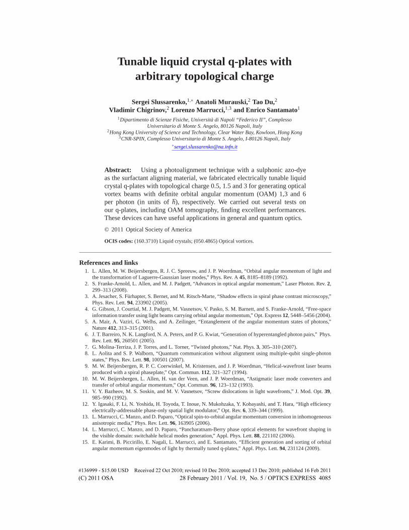
at small angle, have a typical “fork”-like structure [11], in which interference fringes have adisclination, where the optical vortex is located. The disclination order (i.e. the splitting of theinterference line into a higher number of lines) corresponds to the OAM value of the beam, asshown in Fig. 2(d-f, bottom row). We tested also the STOC efficiency of our QPs, defined as theratio between the STOC converted power and the total power in the output. This measurementwas done by registering the power fraction of the light transmitted by the QP having polarizationorthogonal to that of the incident beam. The QP conversion efficiency was changed by changingthe QP retardation δ by applying an external voltage. To avoid electro-chemical effects, weapplied a 2 kHz square-shaped voltage. The measurements were done at 543.5 nm and 633 nmlight wavelengths. The results for the q = 0.5 QP are shown in Fig. 3(a). We obtained a STOCefficiency of up to 99% for all fabricated QPs. Due to unavoidable reflection, diffusion, andabsorption losses in the QP, the overall STOC efficiency defined as the ratio between the STOCconverted power in the output and the total incident power was found about 86% for all ourQPs. These losses, however, could be easily avoided by adding an antireflection coating.
Fig. 3. (Color online) (a) – fraction of the output power converted by STOC in the QP as afunction of the applied voltage. Red line - 633 nm input beam wavelength, green line - 534.5nm input beam wavelength. (b) – time behavior of the QP upon sending two consecutive ACpulses that correspond to the minimum and maximum conversion efficiency. The intensitypatterns in the insets show the on-off switching of the vortex beam with � = 1. The datarefer to the QP with q = 0.5.
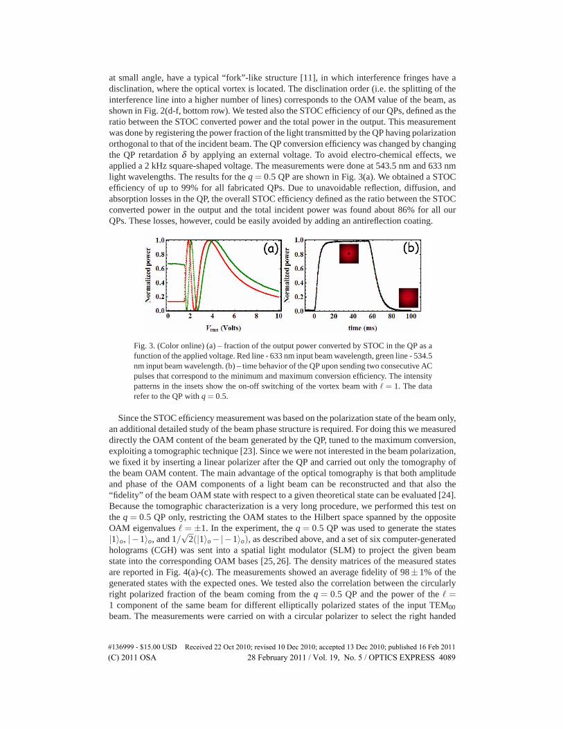
Since the STOC efficiency measurement was based on the polarization state of the beam only,an additional detailed study of the beam phase structure is required. For doing this we measureddirectly the OAM content of the beam generated by the QP, tuned to the maximum conversion,exploiting a tomographic technique [23]. Since we were not interested in the beam polarization,we fixed it by inserting a linear polarizer after the QP and carried out only the tomography ofthe beam OAM content. The main advantage of the optical tomography is that both amplitudeand phase of the OAM components of a light beam can be reconstructed and that also the“fidelity” of the beam OAM state with respect to a given theoretical state can be evaluated [24].Because the tomographic characterization is a very long procedure, we performed this test onthe q = 0.5 QP only, restricting the OAM states to the Hilbert space spanned by the oppositeOAM eigenvalues � = ±1. In the experiment, the q = 0.5 QP was used to generate the states|1〉o, |−1〉o, and 1/
√2(|1〉o−|−1〉o), as described above, and a set of six computer-generated
holograms (CGH) was sent into a spatial light modulator (SLM) to project the given beamstate into the corresponding OAM bases [25, 26]. The density matrices of the measured statesare reported in Fig. 4(a)-(c). The measurements showed an average fidelity of 98± 1% of thegenerated states with the expected ones. We tested also the correlation between the circularlyright polarized fraction of the beam coming from the q = 0.5 QP and the power of the � =1 component of the same beam for different elliptically polarized states of the input TEM00
beam. The measurements were carried on with a circular polarizer to select the right handed
#136999 - $15.00 USD Received 22 Oct 2010; revised 10 Dec 2010; accepted 13 Dec 2010; published 16 Feb 2011(C) 2011 OSA 28 February 2011 / Vol. 19, No. 5 / OPTICS EXPRESS 4089
Fig. 4. (Color online) (a)-(c) – the real components of the density matrices of the OAMstates, reconstructed via quantum tomography process for the |1〉o, |− 1〉o and 1√
2(|1〉o −
|−1〉o) states respectively. (d) - fraction of the �= 1 beam intensity as the function of thefraction of the right polarized output beam, for different elliptically polarized inputs. Thedata refer to the QP with q = 0.5
polarization and a suitable fork hologram to select the � = 1 OAM component. The resultsare shown in Fig. 4(d). We found a standard deviation of σ = 0.02 from perfect one-to-onecorrelation between the circular right polarization state of photons and their OAM value �= 1.As the final test, we measured the switching speed of the QP with q = 0.5 between the lastminimum conversion point where the output beam has �= 0 and the last maximum conversionpoint where the output beam has � = 1. These points are located at 2.4 and 3.7 Volts rms inFig. 3, respectively (for 633 nm). The switching times were found to be around 25-30 ms, asshown in Fig. 3(b). The intensity profiles in the insets show the on-off switching of the vortexbeam with �= 1.
4. Conclusions
In conclusion, using a photoalignment technique we realized several nematic liquid crystal QPswith the topological charge q different from q = 1, including fractionary half-integer charges.The optical phase retardation of our QPs can be tuned by external electric field, that allows tosimplify the manufacturing procedure, removing particular requirements for the cell gap andreach high conversion efficiencies (up to 99%) for different wavelengths of the input light inreal time. Our method is siutable for manufacturing tunable q-plates with arbitrary charge q.
Acknowledgments
Financial support from grants HKUST CERG 612208, CERG 612310, CERG 612409 and fromthe Seventh Framework Programme of the European Commission, under FET-Open grant num-ber: 255914, “PHORBITECH”, is gratefully acknowledged.
#136999 - $15.00 USD Received 22 Oct 2010; revised 10 Dec 2010; accepted 13 Dec 2010; published 16 Feb 2011(C) 2011 OSA 28 February 2011 / Vol. 19, No. 5 / OPTICS EXPRESS 4090