Abstract: An elastomer-based tunable liquid-filled microlens array integrated on top of a microfluidic network is fabricated using soft lithographic techniques. The simultaneous control of the focal length of all the microlenses composing the elastomeric array is accomplished by pneumatically regulating the pressure of the microfluidic network. A focal length tuning range of hundreds of microns to several millimeters is achieved. Such an array can be used potentially in dynamic imaging systems and adaptive optics.
References and links 1. M. H. Wu, G. M. Whitesides, “Fabrication of Diffractive and Micro-optical Elements Using Microlens
Projection Lithography,” Adv. Mater. 14, 1502 (2002). 2. O. Matoba, E. Tajahuerce, B. Javidi, “Three-dimensional object recognition based on multiple perspectives
imaging with microlens arrays,” LEOS 2001. 14th Annual Meeting of the IEEE Lasers and Electro-Optics Society. Part vol.2, pp.495-6, 2001, Piscataway, NJ, USA.
3. H. Hamam, “A two-way optical interconnection network using a single mode fiber array,” Opt. Commun. 150, 270 (1998).
4. J.C. Roulet , R. Volkel, HP Herzig, E Verpoorte, NF de Rooij, R Dandliker, ”Fabrication of multilayer systems combining microfluidic and microoptical elements for fluorescence detection,” J. Microelectromech. S. 10 (4), 482-491 (2001).
5. L. G. Commander, S. E. Day, and D. R. Selviah, “Variable focal length microlenses,” Opt. Commun. 177, 157 (2000).
6. S. Kwon, and L. P. Lee, “Focal length control by microfabricated planar electrodes-based liquid lens (µPELL),” 11th International conference on solid-state sensors and actuators: Transducers’01, Munich, Germany, June 10-14, 2001.
7. T. Krupenkin, S. Yang, and P. Mach, “Tunable liquid microlens,” Appl. Phys. Lett. 82, 316 (2003). 8. N. Sugiura and S. Morita, “Variable-focus liquid-filled optical lens,” Appl. Opt. 32, 4181, (1993). 9. D. Zhang,V.Lien,Y. Berdichevsky, J. Choi, Y.H. Lo, “Fluidic adaptive lens with high focal length
tunability,” Appl. Phys. Lett. 82 (19), 3171-3172 (2003). 10. J. Cooper MC Donald, George M. Whitesides, “Poly(dimethylsiloxane) as a Material for Fabricating
Fabrication in Polydimethylsiloxane (PDMS) Elastomer,” J. Microelectromech. S. 9 (1), 76-81 (2000). 12. ABCR 1994/1995. Research Chemical and Metals. 13. C. Luo, J. Garra, T.W. Schneider, R. White, J. Currie, M. Paranjape, “Determining local residual stress of
polydimethylsiloxane using ink dots, and stiffening polydimethylsiloxane using SU-8 particles,” J. Micromech. Microeng. 12 (5), 677-681 (2002).
1. Introduction
Single microlens and microlens arrays have been developed in the past for applications in photolithography [1], imaging [2], optical communications [3], and more recently, for lab-on-a-chip systems [4] as the multiplex focusing components. Dynamically tunable lenses have also been reported as an initial effort to extend the current capabilities and applications of such microlenses. These tunable lenses eliminate the need for mechanical optical alignment or
(C) 2003 OSA 22 September 2003 / Vol. 11, No. 19 / OPTICS EXPRESS 2370#2784 - $15.00 US Received July 22, 2003; Revised September 02, 2003
scanning. Liquid crystal immersed microlenses [5], and variable focal length liquid lenses controlled by electrowetting [6,7] have been proposed to fulfill these needs. The liquid crystal microlenses suffer from aberrations due to non-uniformities in the electric field. On the other hand, the operation of electrowetting-based microlenses requires high driving voltages and is accompanied by liquid evaporation.
An alternative approach was proposed by Sugiura et al. and Zhang et al. [8,9]. They fabricated centimeter-scale pneumatically activated liquid-filled optical lenses with high focal length tunability. The performance of these lenses is strongly influenced by the weight of the liquid. The weight of the liquid induces non-symmetrical deformation of the lens surface when the lens is placed on a non–horizontal plane. Moreover the proposed fabrication process makes it difficult to create arrays of lenses that are necessary in various muliplexed optical systems.
In this work, we report an integrated tunable liquid-filled microlens array on a microfluidic network to simultaneously control the focal length of multiple microlenses. The microfluidic network does not interfere with the microlens array and thus does not alter the shape of each deformed lens. The focal length of each lens is dynamically adjusted by pneumatically controlling the pressure within the microlfuidic network. A focal length tuning range of hundreds of microns to several millimeters is achieved.
2. Liquid-filled microlens array
The microlens array consists of 200 micron in diameter and 100-micron thick circular chambers covered with a 40-micron thick flexible membrane made of polydimethyl-siloxane (PDMS) elastomer [10]. A microfluidic network is integrated on the bottom of the array to deliver and pressurize the liquid into the circular chambers (Fig. 1). The chambers are pre-filled with any liquid whose index of refraction is equal or higher than that of PDMS (nPDMS=1.41) in order for a positive plano-convex lens array to be formed. A pneumatic pump having a pressure regulator is used to inflate the PDMS membrane. The focal length of all the microlenses is simultaneously adjusted at the desired value by simply regulating the pressure.
Fig. 1. Optical micrograph of the microlens array. Upon pressurizing the elastomeric liquid filled chamber, the membrane deforms forming a plano-convex lens array.
The fabrication process of the array is illustrated in Fig. 2. A 13 micron thick layer of SU-
8 is patterned on a silicon wafer to form the mold for the microfluidic network. A second 100 micron thick layer of SU-8 is patterned on top of the first layer to create the circular chambers. The two SU-8 layers are photolithographically aligned using a stepper with sub-micron misalignment error. The PDMS prepolymer mixture is spin cast over the mold at 600 rpm for 1 minute resulting in a total thickness of approximately 140 microns. The thickness of the PDMS membrane (140–100=40 microns) was optically measured by inspecting the cross
PDMS membrane
1. The lens array is filled with liquid
2. The array is pressurized to form the lenses
PDMS LIQUID GLASS
Circular chamber
400 µm Microfluidic Channels
Microlenses
(C) 2003 OSA 22 September 2003 / Vol. 11, No. 19 / OPTICS EXPRESS 2371#2784 - $15.00 US Received July 22, 2003; Revised September 02, 2003
section of diced chips under a light microscope. A 10% variation of the PDMS thickness across the wafer was observed. The PDMS mixture is subsequently cured on a hot plate for 15 minutes at 150 0C. The cured PDMS is peeled off from the mold, treated with oxygen plasma at 30 Watts for 30 seconds and then irreversibly bonded to a glass substrate [11]. Since the PDMS layer contains both the microfluidic network and the circular chambers, no alignment is required during the bonding process. Openings are created in the PDMS for the fluidic inlets and outlets using a blade. Plastic capillary tubes are finally attached on the openings of the PDMS using a high strength epoxy to avoid any leakage (JB Kwik from JB Weld, the bonding strength is around 5500 KPa for steel according to the manufacturer).
Fig. 2. The fabrication process for integrating microfluidics on bottom of the microlens array (the dotted lines represent a microchannel that connects the two chambers but is not on the same plane as the above cross-sectional view).
The two-layer fabrication process was developed in order to decouple the microlenses
from the microfluidic network and thus minimize the distortion of the circular shape of the lenses.
Due to the excellent optical properties of PDMS (Fig. 3), the proposed microlens array can be used from near ultra violet to near infrared applications.
100 200 300 400 500 600 700 800 900
Wavelength (nm)
50
60
70
80
90
100
Tra
nsm
issi
on (
%)
Fig. 3. Spectral transmission range of PDMS elastomer (the spectrum was obtained from 1 mm thick PDMS sample using an Ocean Optics SD2000 spectrometer).
(C) 2003 OSA 22 September 2003 / Vol. 11, No. 19 / OPTICS EXPRESS 2372#2784 - $15.00 US Received July 22, 2003; Revised September 02, 2003
300 µm
230 µm
3. Lens profile and membrane deformation
The dependence of the membrane deformation on the applied pressure was experimentally monitored using a white-light interferometer (Wyko NT3300). Figure 4 shows a typical two-dimensional profile of a pressurized microlens. The lens was pre-coated with a thin gold layer in order to obtain a clear interferometric image. The microfluidic channel that runs beneath has negligible effect on the shape of the lens since no distortion is observed. All measurements were made on an air-filled microlens array.
Fig. 4. Optical interferometric image of a single PDMS microlens at 20 KPa.
The maximum displacement of the membrane –corresponding to the center of the microlens- versus applied pressure is depicted in Fig. 5. A finite element analysis software (ANSYS) was also used to simulate the mechanical deformation of the membrane under uniform pressure. The thickness and Young’s modulus of the PDMS membrane were assumed to be 40 microns and 3 MPa [12] respectively and the Poisson ratio equal to 0.49. Simulated values agree with measured values throughout the full range of applied pressures.
0 20 40 60 80
Pressure (KPa)
0
4
8
12
De
flect
ion
(m
icro
ns)
Measured
Simulation
Fig. 5. Maximum membrane deflection versus pressure. The maximum deflection is normalized to the initial zero-pressure deflection.
(C) 2003 OSA 22 September 2003 / Vol. 11, No. 19 / OPTICS EXPRESS 2373#2784 - $15.00 US Received July 22, 2003; Revised September 02, 2003
Measurements taken at zero applied pressure indicate an initial curvature of the PDMS membrane. At zero pressure, the center point of the lens is displaced 1.57 microns higher than the flat region outside the lens, resulting in a lens with an initial positive curvature of 9 mm. The residual stress created during PDMS polymerization is suspected to have caused the observed initial curvature [13]. The maximum membrane displacement mentioned above (figure 4) was normalized to the zero-pressure displacement (1.57 microns) in order to compare the predicted with the experimental results.
Finite element simulations were performed to visualize the cross sectional view of a single deformed membrane (Fig. 6). Simulations of a 3x3 lens array were also carried out but are not presented since no cross talk between adjacent lenses was observed.
Fig. 6. Cross section view of the PDMS membrane pressurized at 20 KPa (the scale represents vertical displacement in microns). The finite element simulation reveals two radii of curvature.
It is clear that there is a difference between the maximum deflection of the outer (top)
surface of the membrane and the inner (bottom) one. The inner surface of the membrane deflects more than the outer one resulting in a smaller radius of curvature. The inner radius of curvature can be estimated by drawing a circle that passes through the center point and the two edges of the inner surface. Figure 7 illustrates the outer and inner radius of curvature as those measured and calculated from the interferometric lens profile and the ANSYS simulations respectively.
0 20 40 60 80
Pressure (KPa)
0
2
4
6
8
10
Ra
diu
s o
f C
urv
atu
re (
mm
)
Outer Radius (Measured)
Inner Radius (Simulated)
Fig. 7. Outer and inner radius of curvature versus applied pressure.
0 0.44 0.87 1.31 1.74 2.18 2.62 3.05 3.49 3.92
Rinner Router
Maximum deflection of the bottom membrane surface
Maximum deflection of the top membrane surface
(C) 2003 OSA 22 September 2003 / Vol. 11, No. 19 / OPTICS EXPRESS 2374#2784 - $15.00 US Received July 22, 2003; Revised September 02, 2003
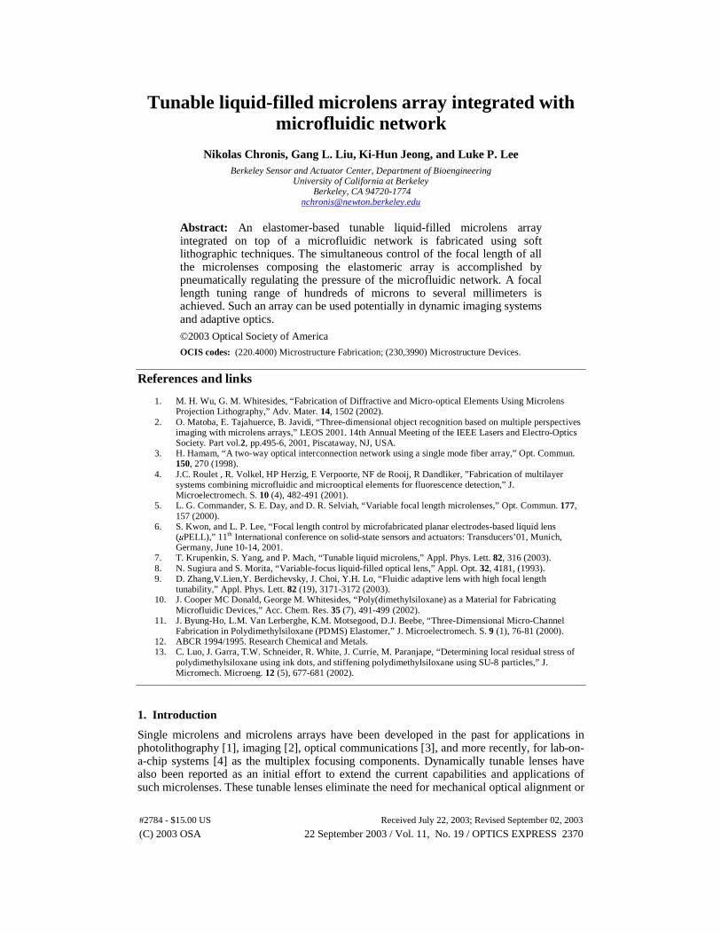
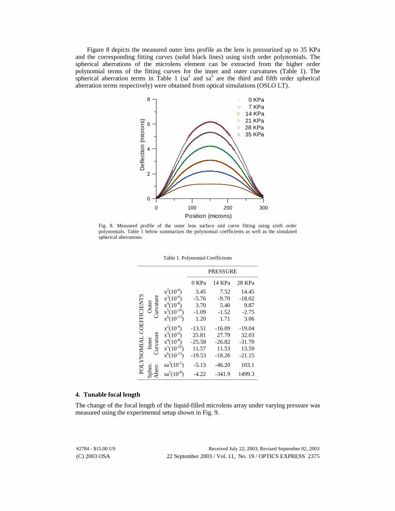
Figure 8 depicts the measured outer lens profile as the lens is pressurized up to 35 KPa and the corresponding fitting curves (solid black lines) using sixth order polynomials. The spherical aberrations of the microlens element can be extracted from the higher order polynomial terms of the fitting curves for the inner and outer curvatures (Table 1). The spherical aberration terms in Table 1 (sa3 and sa5 are the third and fifth order spherical aberration terms respectively) were obtained from optical simulations (OSLO LT).
0 100 200 300
Position (microns)
0
2
4
6
8
De
flect
ion
(m
icro
ns)
7 KPa0 KPa
14 KPa21 KPa28 KPa35 KPa
Fig. 8. Measured profile of the outer lens surface and curve fitting using sixth order polynomials. Table 1 below summarizes the polynomial coefficients as well as the simulated spherical aberrations.
The change of the focal length of the liquid-filled microlens array under varying pressure was measured using the experimental setup shown in Fig. 9.
(C) 2003 OSA 22 September 2003 / Vol. 11, No. 19 / OPTICS EXPRESS 2375#2784 - $15.00 US Received July 22, 2003; Revised September 02, 2003
Focal Plane
Pneumatic Pump
Laser Beam
Microscope Objective
Microlens Array
CCD Camera
XYZ Micromanipulator
Fig. 9. The experimental setup for measuring the focal length of the variable-focus microlens. A 2 mm in diameter collimated laser beam with a peak wavelength of 532 nm impinges
perpendicular to the microlens array. Upon pressurizing the liquid-filled chamber, the membrane deforms, focusing the collimated light. The microlens array sits on a digital controlled XYZ micromanipulator. The focal spot image is visualized with a CCD camera by adjusting the vertical distance between the microlens and the microscope objective. A pneumatic pump is used to control the pressure in the microfluidic chambers.
The focal length was measured from the bottom (inner) surface of the undeformed PDMS membrane. The bottom surface of the membrane corresponds to the zero reference point of the micromanipulator. When the membrane deforms under pressure, the focal plane is decreased. By vertically adjusting the micromanipulator, the focal plane of the microlens array is brought into focus, and the corresponding distance is recorded. The positioning precision of the XYZ micromanipulator is less than 0.2 microns. Therefore the accuracy of the measurement is limited by one’s ability to visually identify the smaller and more intense focused spot while observing it real time through the CCD camera.
Two sets of focal length measurements were made on the microlens array using microscope immersion oil (index of refraction n=1.51) and UV curable polymer (Norland 63, n=1.56) as a filling liquid. A typical example of the focal length and the corresponding f-number (focal ratio) versus applied pressure is shown in Fig. 10.
0 10 20 30 40
Pressure (KPa)
0
2000
4000
6000
8000
10000
Foc
al L
engt
h (m
icro
ns)
Oil
SimulationNorland 63
0
10
20
30
40
50
F-n
um
be
r
Fig. 10. Focal length versus pressure for an oil and UV curable polymer-filled microlens.
In both cases for zero pressure the focal length had a finite value, verifying the initial
radius of curvature measured using the optical interferometer. Unexpectedly, the oil-filled
(C) 2003 OSA 22 September 2003 / Vol. 11, No. 19 / OPTICS EXPRESS 2376#2784 - $15.00 US Received July 22, 2003; Revised September 02, 2003
20 KPa 10 KPa 0 KPa Microlens
microlenses had much shorter focal lengths than the Norland 63-filled ones for the same applied pressure. The main reason for this effect was probably due to the swelling of the PDMS membrane when exposed to oil. Such an assumption is justified by the measured small focal length at zero pressure. Focal length measurements of Norland 63-filled lenses on the other hand were in good agreement with the simulation results, indicating minimum liquid permeability of the UV curable polymer to PDMS. A minimum value of f-number equal to 3.3 is obtained for an oil-filled lens at 35 KPa. Lower f-numbers can be obtained with thinner membranes, since they are more compliant. Simulations were performed using OSLO LT, where both the inner and outer curvature of the membrane were obtained as previously described (Fig. 7). The refractive index of Norland 63 was assumed to be 1.56.
Although oil and Norland 63-filled microlens have different initial focal length, the percentage change of the focal length from the initial value versus pressure is almost identical (Fig. 11). By varying the pressure from 0 KPa to 35 KPa, the focal length changes by more than 70% in both cases. The error bars correspond to four sets of measurements and are mainly due to the uncertainty in determining the exact focal point as well as due to the nonuniformity of the membrane thickness during PDMS spinning.
0 10 20 30 40
Pressure (KPa)
0
20
40
60
80
Fo
cal L
en
gth
Ch
an
ge
(%
)
Oil
Norland 63
Fig. 11. Percentage focal length change versus pressure for an oil-filled and UV curable polymer-filled (Norland 63) microlens.
The ability to dynamically tune the microlens array is illustrated in Fig. 12. We placed a
sample containing gold lines of different widths beneath our microlens array and intentionally defocus the image. When no pressure is applied, the image through a single microlens is blurry and no patterns can be observed. When the microlens is pressurized, 4 microns and 3 microns line patterns can be distinguished at 10 KPa and 20 KPa respectively.
Fig. 12. Variable focusing of the oil-filled microlens array by changing the pressure. A sharp focused spot is obtained when the focal plane comes in focus.
(C) 2003 OSA 22 September 2003 / Vol. 11, No. 19 / OPTICS EXPRESS 2377#2784 - $15.00 US Received July 22, 2003; Revised September 02, 2003
5. Conclusions
An elastomer-based tunable liquid-filled microlens array is fabricated using soft lithographic techniques. The focal length of all the microlenses composing array is pneumatically controlled through a microfluidic network that evenly pressurizes each microlens. A focal length tuning range of hundreds of microns to several millimeters is achieved. The developed microlens array can be used potentially in various dynamic imaging systems and adaptive optics applications. Alternatively, if a UV curable polymer is implemented as a filling liquid, a solid microlens array with the desired focal length can be obtained upon exposure to UV light. Such an array can be used in optical communications, compound photonic devices as well as in lab-on-a-chip systems.
Acknowledgments
This work is supported by the DARPA Bio-Optic Synthetic Systems (BOSS) program.
(C) 2003 OSA 22 September 2003 / Vol. 11, No. 19 / OPTICS EXPRESS 2378#2784 - $15.00 US Received July 22, 2003; Revised September 02, 2003