IT/P2-4 1 Tungsten and Beryllium Armour Development for the JET ITER-like Wall Project H. Maier 1), T. Hirai 2), M. Rubel 3), R. Neu 1), Ph. Mertens 2), H. Greuner 1), Ch. Hopf 1), G. F. Matthews 4), O. Neubauer 2), G. Piazza 5), E. Gauthier 6), J. Likonen 7), R. Mitteau 6), G. Maddaluno 8), B. Riccardi 8), V. Philipps 2), C. Ruset 9), C. Lungu 9), I. Uytdenhouwen 10) and JET EFDA contributors 1 1) Max-Planck-Institut für Plasmaphysik, Euratom Association, Garching, Germany 2) Forschungszentrum Jülich, Euratom Association, Jülich, Germany 3) Royal Institute of Technology, Association Euratom-VR, Stockholm, Sweden 4) Association Euratom-UKAEA, Culham Science Centre, Abingdon, UK 5) EFDA-Close Support Unit, Culham Science Centre, Abingdon, UK 6) Association Euratom-CEA, Cadarache, DSM/DRFC, Saint Paul Lez Durance, France 7) Association Euratom-TEKES, VTT Processes, Finland 8) Association Euratom-ENEA, Frascati, Italy 9) National Institute for Laser, Plasma and Radiation Physics, Association Euratom-MEdC, Bucharest, Romania 10) SCK-CEN, The Belgian Nuclear Research Centre, Euratom Association, Mol, Belgium / Ghent University, B-9000 Ghent, Belgium e-mail contact of main author: [email protected]Abstract. The operational behaviour and the interplay of the ITER plasma facing material choice has never been investigated in a tokamak experiment. This motivated the ITER-like Wall Project at JET in which the present main chamber CFC tiles will be exchanged with Be tiles and in parallel a fully tungsten-clad divertor will be prepared. Among the scientific objectives of the ITER-like Wall project are general questions of plasma operation with a low melting Be wall, compatibility of all envisaged ITER scenarios with a W divertor, tritium retention and removal and mixed materials effects, erosion behaviour and lifetime investigations. Three R&D programs were initiated: Be coatings on inconel as well as Be erosion markers are developed for the first wall of the main chamber. This work is done by the Romanian Euratom association under the coordination of the Swedish Royal Institute of Technology. Forschungszentrum Jülich, Germany, developed a conceptual design for a bulk W horizontal target plate, based on an assembly of tungsten lamellae. For all other divertor parts five Euratom Fusion Associations performed R&D to provide the technology to coat the 2-directional CFC material used at JET with thin tungsten coatings. High heat flux screening and cyclic loading tests carried out on the Be coatings on Inconel showed excellent performance, above the required power and energy density. For the bulk W, a design was developed to minimise electromagnetic forces. The design consists of stacks of W lamellae of 6 mm width that are insulated in toroidal direction. High heat flux tests of a test module were performed on the electron beam facility JUDITH at Forschungszentrum Jülich at an absorbed power density up to 9 MW/m² for more than 150 pulses and finally with increasing power loads leading to surface temperatures in excess of 3000°C. No macroscopic failure occurred during the test while SEM showed the development of microcracks on the loaded surface. The W coated CFC tiles were subjected to heat loads with power densities ranging up to 23.5 MW/m². In a second step, a selection of coatings was exposed to cyclic heat loading for 200 pulses at 10.5 MW/m². All coatings developed cracks perpendicular to the CFC fibres due to the stronger contraction of the coating upon cool-down after the heat pulses. 1. Introduction The operational behaviour and the interplay of the ITER plasma facing material choice (beryllium in the main chamber, tungsten in the baffle areas and CFC carbon at the vertical targets) has never been investigated in a tokamak experiment. This motivated the ITER-like 1 See the Appendix of M. L.Watkins et al., Fusion Energy 2006 (Proc. 21st Int. Conf. Chengdu, 2006) IAEA, (2006)
Transcript
IT/P2-4
1
Tungsten and Beryllium Armour Development for the JET ITER-like Wall Project
H. Maier 1), T. Hirai 2), M. Rubel 3), R. Neu 1), Ph. Mertens 2), H. Greuner 1), Ch. Hopf 1), G. F. Matthews 4), O. Neubauer 2), G. Piazza 5), E. Gauthier 6), J. Likonen 7), R. Mitteau 6), G. Maddaluno 8), B. Riccardi 8), V. Philipps 2), C. Ruset 9), C. Lungu 9), I. Uytdenhouwen 10) and JET EFDA contributors1 1) Max-Planck-Institut für Plasmaphysik, Euratom Association, Garching, Germany 2) Forschungszentrum Jülich, Euratom Association, Jülich, Germany 3) Royal Institute of Technology, Association Euratom-VR, Stockholm, Sweden 4) Association Euratom-UKAEA, Culham Science Centre, Abingdon, UK 5) EFDA-Close Support Unit, Culham Science Centre, Abingdon, UK 6) Association Euratom-CEA, Cadarache, DSM/DRFC, Saint Paul Lez Durance, France 7) Association Euratom-TEKES, VTT Processes, Finland 8) Association Euratom-ENEA, Frascati, Italy 9) National Institute for Laser, Plasma and Radiation Physics, Association Euratom-MEdC,
Bucharest, Romania 10) SCK-CEN, The Belgian Nuclear Research Centre, Euratom Association, Mol, Belgium / Ghent University, B-9000 Ghent, Belgium e-mail contact of main author: [email protected] Abstract. The operational behaviour and the interplay of the ITER plasma facing material choice has never been investigated in a tokamak experiment. This motivated the ITER-like Wall Project at JET in which the present main chamber CFC tiles will be exchanged with Be tiles and in parallel a fully tungsten-clad divertor will be prepared. Among the scientific objectives of the ITER-like Wall project are general questions of plasma operation with a low melting Be wall, compatibility of all envisaged ITER scenarios with a W divertor, tritium retention and removal and mixed materials effects, erosion behaviour and lifetime investigations. Three R&D programs were initiated: Be coatings on inconel as well as Be erosion markers are developed for the first wall of the main chamber. This work is done by the Romanian Euratom association under the coordination of the Swedish Royal Institute of Technology. Forschungszentrum Jülich, Germany, developed a conceptual design for a bulk W horizontal target plate, based on an assembly of tungsten lamellae. For all other divertor parts five Euratom Fusion Associations performed R&D to provide the technology to coat the 2-directional CFC material used at JET with thin tungsten coatings. High heat flux screening and cyclic loading tests carried out on the Be coatings on Inconel showed excellent performance, above the required power and energy density. For the bulk W, a design was developed to minimise electromagnetic forces. The design consists of stacks of W lamellae of 6 mm width that are insulated in toroidal direction. High heat flux tests of a test module were performed on the electron beam facility JUDITH at Forschungszentrum Jülich at an absorbed power density up to 9 MW/m² for more than 150 pulses and finally with increasing power loads leading to surface temperatures in excess of 3000°C. No macroscopic failure occurred during the test while SEM showed the development of microcracks on the loaded surface. The W coated CFC tiles were subjected to heat loads with power densities ranging up to 23.5 MW/m². In a second step, a selection of coatings was exposed to cyclic heat loading for 200 pulses at 10.5 MW/m². All coatings developed cracks perpendicular to the CFC fibres due to the stronger contraction of the coating upon cool-down after the heat pulses.
1. Introduction
The operational behaviour and the interplay of the ITER plasma facing material choice (beryllium in the main chamber, tungsten in the baffle areas and CFC carbon at the vertical targets) has never been investigated in a tokamak experiment. This motivated the ITER-like 1 See the Appendix of M. L.Watkins et al., Fusion Energy 2006 (Proc. 21st Int. Conf. Chengdu, 2006) IAEA, (2006)
Wall Project at JET [1, 2] in which the present main chamber CFC tiles will be fully exchanged with beryllium tiles (about 4000 different tiles) and in parallel a fully tungsten-clad divertor will be prepared. To apply the coatings, a second batch of divertor CFC tiles will be procured, so JET will have the choice to operate with tungsten and CFC in the divertor or with a full tungsten divertor which is the present first option to start with. A large part of the divertor surface will be equipped with an economically viable coating of tungsten on the present JET CFC material. Among the scientific objectives of the ITER-like Wall project are general questions of plasma operation with a low melting beryllium wall, compatibility of all envisaged ITER scenarios with a tungsten divertor, tritium retention and removal and mixed materials effects, erosion behaviour and lifetime investigations. The intended physics programme includes operation at high stored energy (>20 MJ) at high Ip and Bt, with the possibility of large ELMs. Since this may exceed the technical limit for tungsten coatings, a bulk tungsten target is developed for the horizontal target row of the divertor that will experience the highest power loads in ITER-like high triangularity configurations. In parallel, this solution will allow to study important ITER relevant materials aspects of e.g. tungsten thermal fatigue during repetitive ELM loading, melt layer behaviour, interaction of beryllium with tungsten and material migration in tungsten gaps. The main chamber poloidal limiters will be manufactured from bulk beryllium. For the recessed surfaces in between these limiters beryllium coatings on Inconel steel panels will be applied. To qualify solutions for beryllium coatings, tungsten coatings, and bulk tungsten three R&D tasks were set up [3, 4]: Be coatings on inconel steel are developed by the Romanian Euratom Association under the coordination of the Swedish Royal Institute of Technology. This also includes the development of diagnostic tiles to determine the gross beryllium erosion. This task is presented in section 2. For the tungsten divertor, two R&D programs were initiated: Forschungszentrum Jülich, Germany, developed a conceptual design for a bulk tungsten horizontal target plate, based on an assembly of tungsten lamellae. This is presented in section 3. For all other divertor parts, five Euratom Fusion Associations performed R&D to provide the technology to coat the 2-directional CFC material used at JET with thin tungsten coatings. The resulting tungsten coated CFC tiles underwent a programme of tests at Max-Planck-Institut für Plasmaphysik, Garching, Germany. Results from this test programme are presented in section 4.
2. R&D on Beryllium Coatings and Marker Tiles
The material for the main chamber wall is Be: bulk limiters and Be coatings on inconel tiles of the inner wall and upper dump plate cladding. Activities related to the development of coatings are in two areas: (a) protective layers on Inconel tiles to ensure reduced influx of impurities by full coverage of the wall with low-Z material; (b) marker films on bulk Be limiters for the assessment of erosion rates in the main chamber of JET.
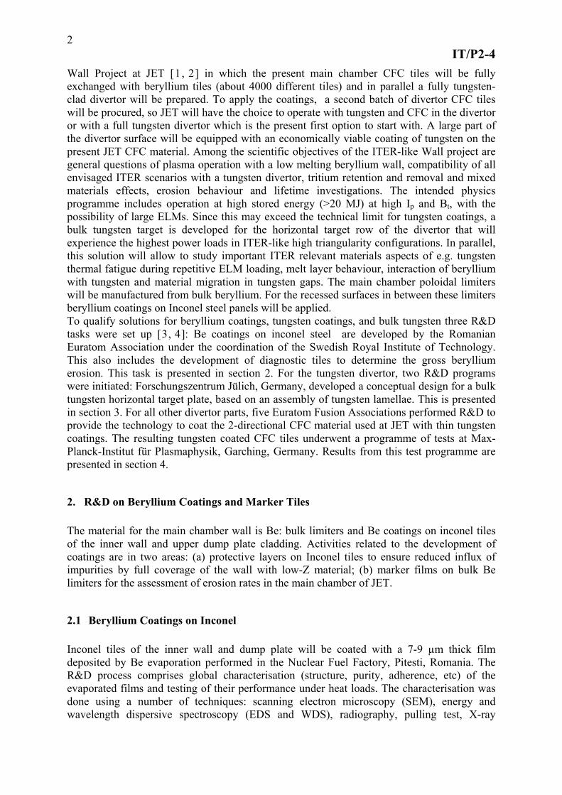
2.1 Beryllium Coatings on Inconel Inconel tiles of the inner wall and dump plate will be coated with a 7-9 µm thick film deposited by Be evaporation performed in the Nuclear Fuel Factory, Pitesti, Romania. The R&D process comprises global characterisation (structure, purity, adherence, etc) of the evaporated films and testing of their performance under heat loads. The characterisation was done using a number of techniques: scanning electron microscopy (SEM), energy and wavelength dispersive spectroscopy (EDS and WDS), radiography, pulling test, X-ray
IT/P2-4
3
5 µm
Fig. 1. Details of surface structure of the evaporated Be layer deposited on cast Inconel.
photoelectron spectroscopy (XPS), atomic force microscopy (AFM) and ion beam analysis (IBA) methods such as nuclear reaction analysis (Nuclear Reaction Analysis with a 2.5 MeV 3He+ beam) and Rutherford backscattering spectroscopy (RBS) using a 2.5 MeV 4He+ beam. Fig. 1 shows the surface structure of an evaporated Be film on cast Inconel. As determined with IBA and EDS, the coating is of high purity and the presence of oxygen (not exceeding 3%) is detected in a thin outermost layer. The film also well adheres to the substrate and no exfoliation has been observed during the long-term storage (8 months) in air. The tests carried out in the electron beam facility JUDITH [5] aimed at the assessment of material performance under heat loads. Two modes of operation were applied: (a) screening test to determine the power and energy density limits, i.e. conditions leading to melting and/or exfoliation; (b) power cycling at the energy level typically deposited onto the cladding during a regular operation of JET: 0.5 MW m-2 in 10 s corresponding to 5 MJ m-2. A graph in Fig. 2 presents an overview of the HHF screening tests carried out in the power density range from 0.4 MW/m2 to 3.0 MW/m2 in pulses lasting up to 11 s (energy density range: 4.4 – 20.0 MJ/m2) [6]. The change of surface temperature is plotted against the energy density deposited on Be-coated inconel coupons of different thickness (d): 3.3 to 4.5 mm. The temperature rise is lower – as expected - for thicker targets. The main result is that layers
Extrapolation: ~11 s HHF pulse on Be/Inconel (3.5 mm)
1200
Tem
pera
ture
[o C]
0
200
400
600
800
1000
0 10 20 30 40
delta T, 3.3 ~ 3.6 mmdelta T, >4.0 mm
~ 11 s pulses, d = 3.3 ~ 3.6 mm
6.2 s pulse, d = 4 mm
~ 11 s pulses, d > 4.0 mm
6.2 s, delta T
Energy density [MJ/m2] Fig. 2. The change of the surface temperature following HHF pulses during the screening test of Be-coated Inconel.
IT/P2-4
4
survive without melting and exfoliation energy loads of up to 20 MJ/m2, i.e. approximately two times greater than required for the regular operation of JET. In the cyclic test 50 consecutive HHF pulses lasting 10 s each were performed at the power level of 1.0 MW/m2 corresponding to the total energy density of 10 MJ/m2. The test has not introduced any noticeable changes in the layer structure. This completed the qualification procedure of the layers leading to the conclusion that the evaporation process can be used for coating of large areas of the JET vessel inner wall.
2.2 Marker Layers for Beryllium Smart Tiles The assessment of beryllium erosion from PFC in the main chamber is crucial for ITER and, therefore, it is an important goal of the ITER-like Wall Project. For that purpose marker tiles will be used. Details regarding the application and experience with marker tiles during previous campaigns at JET can be found elsewhere [7,8]. For the ITER-like wall phase several solid Be limiters will be coated with a high-Z metal interlayer (2-3 µm) and a 7-9 µm Be film. This would allow erosion measurement up to this depth. For assessing erosion greater than that the tiles will have precise notches 10 µm and 20 µm deep. The Be marker layer must be adherent to the substrate and compact to resemble bulk Be in order to make the measurements conclusive. Thermionic Vacuum Arc (TVA) technique based on the electron-induced evaporation [9] has been selected for this purpose. The deposition process has been optimised and a composition of the interlayer has been decided after carrying out tests with nickel, tungsten and rhenium. Nickel, which was the primary choice from the beginning, has been selected because of close values of linear thermal expansion coefficients at room temperature for Ni (13x10-6 K-1) and Be (16x10-6 K-1). The coefficients for other candidates are significantly lower (4.5x10⁻⁶ K-1 for W and 6.6x10⁻⁶ K-1 for Re) thus creating a risk of layer flaking under heat loads. A number of test coupons (2x2x3 cm) have been produced. The adherence of the film has been better than 1.77 MPa as inferred from the pulling test. Characterisation with several surface sensitive techniques is under way. The marker layer performance under power loads will be carried out in JUDITH to complete the process of material qualification. In parallel, erosion behaviour of coatings (both markers and films deposited on cast Inconel) by high fluxes of deuterium plasma will be studied in PISCES-B, a beryllium-compatible simulator of plasma-wall interactions [10].
3. Bulk Tungsten for the Horizontal Target
3.1 Tungsten Lamellae Divertor Tile Design
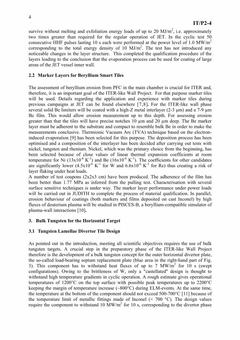
As pointed out in the introduction, meeting all scientific objectives requires the use of bulk tungsten targets. A crucial step in the preparatory phase of the ITER-like Wall Project therefore is the development of a bulk tungsten concept for the outer horizontal divertor plate, the so-called load-bearing septum replacement plate (blue area in the right-hand part of Fig. 3). This component has to withstand heat fluxes of up to 7 MW/m2 for 10 s (swept configurations). Owing to the brittleness of W, only a "castellated" design is thought to withstand high temperature gradients in cyclic operation. A rough estimate gives operational temperatures of 1200°C on the top surface with possible peak temperatures up to 2200°C keeping the margin of temperature increase (~800°C) during ELM-events. At the same time, the temperature at the bottom of the component should not exceed 500-700°C [11] because of the temperature limit of metallic fittings made of Inconel (< 700 °C). The design values require the component to withstand 10 MW/m2 for 10 s, corresponding to the divertor phase
IT/P2-4
5
Fig. 3. Left: Bulk W lamellae concept (only one half shown with W lamellae in place): Right: Cross-section of the JET divertor showing the locations of bulk (blue) and coated solutions (red).
of a tokamak pulse. Two solutions have been considered: (i) an assembly of W lamellae and (ii) a design with W blocks brazed to a CFC tile (a back-up solution). The lamellae-type tile has been developed with high priority and only this concept will be further discussed here. A discussion of the brazed back-up solution can be found in [12]. In parallel, electron beam welding of W/TZM has been studied at CEA Cadarache and FZJ Jülich as an alternative lamellae concept with W plasma facing surface and TZM body. The lamellar design consists of stacks of W lamellae (four of them per tile and two tiles per module), mounted onto a supporting structure, called "wedge". This component had to be designed completely from scratch because the previous supporting structure could not cope with high electromagnetic forces expected when such a fully metallic tile is exposed to both a high toroidal magnetic field (4 T at the centre of the machine) and high poloidal magnetic field variations (up to 100 T/s) and halo current (~20 kA/module) during disruptions. The developed wedge is shown in the left-hand part of Fig. 4 (only one half is shown with the W lamellae in place). The whole concept has been determined by electromagnetic considerations: (i) to minimize eddy currents by cutting conducting loops as far as possible, and (ii) to provide a well-defined path for halo currents: down to the JET base plate. The first objective has led to the sandwiched lamellar design as well as to deep cuts between wedge wings in toroidal direction, as shown in Fig.3; adequate electrical insulation is ensured by ceramic coatings on the spacers between lamellae and on the supporting wedge wing under the lamellae feet. The second condition is fulfilled by direct connection of the tiles to the base plate through the four feet per tile. Mechanical pre-loading of the long bolts that assemble the lamellae is required because of the difference in the thermal expansion of W plus TZM (chosen for the spacers between W-lamellae) as compared to the tie rods. The vertical electromagnetic force is high, estimated to be more than 4 kN per tile (~1.3 kN per stack) [11, 13,14]. To specify preferable W grades for the lamellae, mechanical properties and re-crystallization resistance of various grades have been examined in SCK-CEN, Mol. As a result, sintered and rolled grades were recommended.
3.2 High Heat Flux Testing of Bulk Tungsten Tiles
High-heat flux (HHF) tests were performed in JUDITH, on the test tile shown in Figure 4. No macroscopic damage was observed up to 156 MJ/m2 (7.8 MW/m2 for 20 s) in W components. This is well above the requirement. In the tests of material durability (failure test) 9 MW/m2 was applied for 15 s leading to surface temperatures above 2500°C. Micro-cracks were observed at the loaded surface. The impact of micro-cracks on the performance seemed to be
IT/P2-4
6
Fig. 4. Bulk tungsten test tile for high heat flux tests in the Judith facility
negligible for this degree of cyclic thermal loading, 7~8 MW/m2 for 10 s up to ~150 cycles, since no significant temperature increase was observed [12]. The lamellae concept was also exposed to a fusion plasma in the TEXTOR tokamak at FZ Jülich to confirm both the design feasibility and the options in lamellae size, gap width, shaping of the top surface, and electrical insulation schemes. The deposited power was above the critical threshold onto the test tile in a tokamak discharge and part of the tile melted under this supercritical power loading. Due to the melting, the tungsten lamellae top surface was tapered in a round shape. However, no other damage was observed. The electrical insulator between the lamellae, an Al2O3 coating, kept sufficient resistivity after the exposure. It proved that 1 mm groove in the design concept was large enough to prevent the bridging of two adjacent lamellae under those operation conditions.
4. Tests of Tungsten Coatings on CFC
With the development of tungsten coatings on CFC, the main problem to overcome is the anisotropy and mismatch of the thermal expansion coefficient of CFC with respect to tungsten, see [15]. Preliminary tests already showed that CFC is not as suitable for tungsten coatings as fine grain graphite [16]. To minimize the risk of this task, a variety of coating methods and a selection of coating thicknesses were employed. Using physical vapour (PVD) and chemical vapour deposition (CVD) coatings with thicknesses of 4 and 10 micrometers were deposited; by CVD and vacuum plasma spraying (VPS) coatings with a thickness of 200 micrometers were produced. In total, 14 different types of samples were investigated. The intrinsic stress state of the coatings was investigated by X-ray diffraction, yielding in general stress levels characteristic for the deposition method, e.g. all PVD coatings display intrinsic compressive stresses at levels of several hundred MPa. High heat flux testing of the coatings was performed in the hydrogen beam facility GLADIS [17, 18] in two steps: In a first screening, the samples were subjected to heat loads with power densities ranging from 6 MW/m² to 23.5 MW/m² with surface temperatures exceeding 2000°C. Here all tested coatings developed cracks perpendicular to the fibres due to the stronger contraction of the coating upon cool-down after the heat pulses. This must be considered as a fundamental property of the CFC/tungsten combination which serves to relax stress arising from the thermal expansion mismatch.
IT/P2-4
7
Fig. 5. Photograph of two tiles (height 80mm) during heat loading in GLADIS. The bright horizontal features are fibre planes perpendicular to the surface. The bright vertical feautures on the right-hand tile are developing tensile cracks. The power density is centered in the middle of the tiles.
In addition, some more failures on various length scales occurred. In a second step, a selection of coatings was exposed to cyclic heat loading for 200 pulses at 10.5 MW/m² for 5 s corresponding to surface temperatures of about 1600°C. After the pulses, a distinct sub-mm-scale delamination pattern was observed on most thin coatings due to fatigue. Only the coatings which were deposited by combined magnetron sputtering and ion implantation (CMSII) and were equipped with a Mo interlayer, did not develop this phenomenon. During cyclic loading, some of the 200 micrometer coatings failed by delamination followed by melting. In a last step, a “final” selection of coatings were exposed to ELM-like loading conditions (0.35 GW/m²) for 1000 pulses in JUDITH. Here also the CMSII coatings experienced the above mentioned fatigue phenomenon. Thicker coatings (200µm) showed better resistance against ELM load damage. A metallographic examination of the 200 µm coatings after cyclic loading in GLADIS revealed, however, that also for these thick coatings a local delamination of the coating from the substrate can be observed. This occurs repeatedly at those locations of the substrate surface, where the carbon fibres run parallel to the surface – exactly as it was observed for the thin coatings (see above). The absence of the buckling failure here is attributed to the higher stiffness of the thicker coatings.
5. Summary
Beryllium coatings (7-9 µm) on cast Inconel were tested under heat flux and showed excellent performance, above the required power and energy density. As a result of this successful R&D process, large inconel tiles will be coated with beryllium for the JET inner wall and dump plates. Beryllium marker tiles for the assessment of erosion in the main chamber wall have been developed. The ongoing programme comprises characterisation and testing of the markers under heat fluxes and deuterium plasma impact. An inertially cooled bulk tungsten tile design was developed to be used for the Load Bearing Septum Replacement Plate, i.e. the outer horizontal divertor target in JET. To avoid excessive electromagnetic forces, the design is based on tungsten lamellae. A reduced size test tile showed a high performance fulfilling the requirements. Due to the successful outcome of the
IT/P2-4
8
bulk tungsten tile R&D the design was accepted for inclusion in the procurement phase of the project. The major fraction of the power-loaded first wall surface will be equipped with tungsten coatings on carbon fibre composites. To identify a viable industrial-scale solution for this, a number of different coating types and thicknesses were investigated – mostly by high heat flux tests. 200 micron vacuum plasma-sprayed coatings were chosen for the divertor. PVD coatings of 10 micron thickness produced by combined magnetron and ion implantation in combination with a molybdenum interlayer will be employed in some main chamber locations. References 1 J. Pamela, et al., “An ITER-like Wall for JET”, presented at 17th international conference on plasma surface interaction in controlled fusion devices, Hefei China, 22-26 May 2006. Submitted to J. Nucl. Mater. 2 G. F. Matthews et al., “ITER-like Wall Project Overview”, presented at the 11th International Workshop on Plasma-Facing Materials and Components for Fusion Applications, 2006. Submitted to Physica Scripta 3 G. Piazza et al., “The ITER-like Wall Project”, presented at ICFRM-12, Santa Barbara, December 2006. To be published in J. Nucl. Mater. 4 T. Hirai et al., „R&D on full tungsten divertor and beryllium wall for JET ITER-like wall project“, presented at SOFT 2006. Submitted to Fus. Eng. Des. 5 R. Duwe, W. Kühnlein, M. Münstermann, Proc. SOFT 1994, Fusion Technology (1995) 335. 6 T. Hirai et al., “Characterisation and Heat Flux testing of Beryllium Coatings on Inconel”, presented at the 11th International Workshop on Plasma-Facing Materials and Components for Fusion Applications, 2006. Submitted to Physica Scripta 7 M. Rubel, et al., J. Nucl. Mater.329-333 (2004) 795-799. 8 J.P. Coad et al., Nucl. Fusion 46 (2006) 350-366. 9 C.P. Lungu et al., Surf. Coat. Technol. 200 (2005) 399-405. 10 K. Schmid, M.J. Baldwin, R.P. Doerner, J. Nucl. Mater. 337-339 (2005) 862-866. 11 Ph. Mertens et al. , “Conceptual design for a bulk tungsten divertor tile in JET”, presented at SOFT 2006. Submitted to Fus. Eng Des. 12 T. Hirai et al., “Development and testing of a bulk tungsten tile for the JET divertor”, presented at the 11th International Workshop on Plasma-Facing Materials and Components for Fusion Applications, 2006. Submitted to Physica Scripta 13 A. Borovkov et al., “3-D finite element coupled field analysis of the JET LB-SRP divertor element”, presented at SOFT 2006. Submitted to Fus. Eng Des. 14 S. Sadakov et al., “Design optimisation of a solid tungsten divertor plate for JET resulting from pure electromagnetic consideration”, presented at SOFT 2006. Submitted to Fus. Eng Des. 15 H. Maier et al., “Tungsten Coatings for the JET ITER-like Wall Project”, presented at 17th international conference on plasma surface interaction in controlled fusion devices, Hefei China, 22-26 May 2006. Submitted to J. Nucl. Mater. 16 H. Maier, Mat. Sci. Forum 475-479 (2005) 1377 and references therein 17 H. Greuner et al., Fus. Eng. Des. 75(9) (2005) 333 18 H. Greuner et al., “High Heat Flux Facility GLADIS – Operational Chracteristics and Results of W7-X Pre-Series Target Tests presented at ICFRM-12, Santa Barbara, December 2006. Submitted to J. Nucl. Mater.