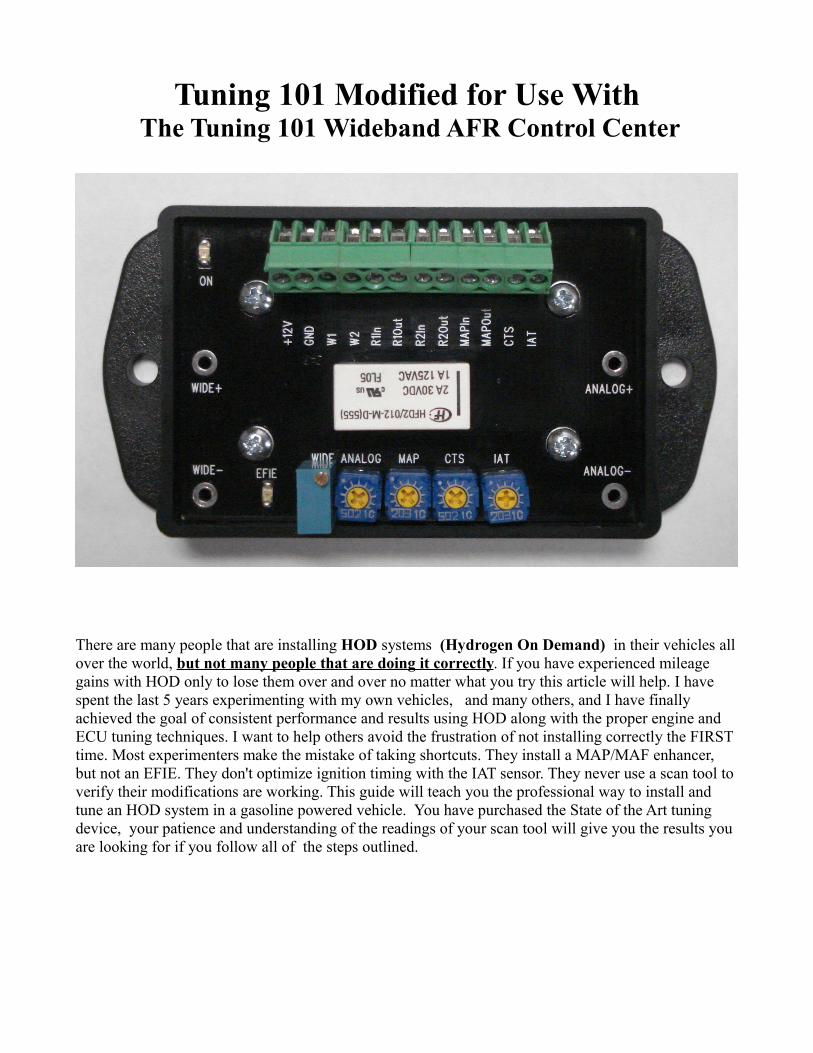
Tuning 101 Modified for Use With The Tuning 101 Wideband AFR Control Center There are many people that are installing HOD systems (Hydrogen On Demand) in their vehicles all over the world, but not many people that are doing it correctly . If you have experienced mileage gains with HOD only to lose them over and over no matter what you try this article will help. I have spent the last 5 years experimenting with my own vehicles, and many others, and I have finally achieved the goal of consistent performance and results using HOD along with the proper engine and ECU tuning techniques. I want to help others avoid the frustration of not installing correctly the FIRST time. Most experimenters make the mistake of taking shortcuts. They install a MAP/MAF enhancer, but not an EFIE. They don't optimize ignition timing with the IAT sensor. They never use a scan tool to verify their modifications are working. This guide will teach you the professional way to install and tune an HOD system in a gasoline powered vehicle. You have purchased the State of the Art tuning device, your patience and understanding of the readings of your scan tool will give you the results you are looking for if you follow all of the steps outlined.
Transcript
Tuning 101 Modified for Use With The Tuning 101 Wideband AFR Control Center
There are many people that are installing HOD systems (Hydrogen On Demand) in their vehicles all over the world, but not many people that are doing it correctly. If you have experienced mileage gains with HOD only to lose them over and over no matter what you try this article will help. I have spent the last 5 years experimenting with my own vehicles, and many others, and I have finally achieved the goal of consistent performance and results using HOD along with the proper engine and ECU tuning techniques. I want to help others avoid the frustration of not installing correctly the FIRST time. Most experimenters make the mistake of taking shortcuts. They install a MAP/MAF enhancer, but not an EFIE. They don't optimize ignition timing with the IAT sensor. They never use a scan tool to verify their modifications are working. This guide will teach you the professional way to install and tune an HOD system in a gasoline powered vehicle. You have purchased the State of the Art tuning device, your patience and understanding of the readings of your scan tool will give you the results you are looking for if you follow all of the steps outlined.
BASELINE- This is THE most important step. Establish what your current highway MPG baseline is by doing a point to point 100 mile or greater highway mileage loop test. Purchase and learn how to use a scan tool. At 55-65 MPH cruise, log your Short-term and Long term fuel trim averages, MAP/MAF number, TPS number, ignition timing, and typical IAT and CTS temps. Repeat the test and the logging at least twice. If you don't know what your baseline is, you won't know if you've accomplished your goals.
THE ELECTROLYZER- This is the core of your HOD system. Just like a radio is of little use without a good antenna, an HOD system is of little use with a poor electrolyzer. Try as you might to increase engine efficiency, an inefficient electrolyzer will soak up most of any gains you might achieve by putting out too little LPM of hydroxy for too much current from your battery/alternator.
With most vehicles it's important to stay under 20 amps of current draw to avoid electrical strain on the alternator/battery. At 20 amps you should be seeing at least 3 LPM from your electrolyzer with minimal heat. (under boiling temperature) In most cases you should NEVER need to exceed 15 amps of total draw for the supplemental effect of hydroxy to work.
Note** It is never advisable to install a generator that draws more than 15% of your alternators rated amperage output.
Contrary to popular belief, it's not always best to run the maximum hydroxy you can produce. For 4 cylinder cars usually ¼ to ½ LPM is plenty to get the job done. 6 or 8 cylinders get a little better kick from 1-2 LPM. The people out there on YouTube that are trying to build these "mega-cells" for HOD purposes are totally missing the point. Are you trying to run the car on water or simply enhance combustion? Pick one. Too much HHO and you'll actually force the engine to work harder, fighting the upward motion of the piston, screwing up engine timing, and more. A little water gas goes a long way, but at least ¼ LPM is essential to begin to do anything. Controlling the output of your electrolyzer is a must. This is best accomplished with a CCPWM or a manually operated PWM. Our New Black Box Controller is the most advanced control system on the market at this point in time. The Mighty Mite 5.0+1 has the highest efficiency rating of any electrolyzer currently on the market, With an efficiency rating exceeding 200%. No other electrolyzer that I know of has reached the 100% level yet.
Do lots (and I mean lots) of research on electrolyzers. The Mighty Mite 5.0+1 has the best LPM for the current draw, with the lowest heat. (although many others lie about their specs so use caution)Look for lasting build quality and know what's inside anything you purchase. Do not accept anything less than 316L grade stainless steel for electrodes. Even 304 WILL break down over time, so make sure it's 316L or better. Try to find positive postings or results with a specific electrolyzer before you purchase it.
Mount your electrolyzer in a suitable place away from moving parts and away from the engine heat as much as possible. Wire the positive lead through a solenoid (relay) and an ammeter. Negative goes straight to a good vehicle ground. Use a ignition active source to fire the solenoid and a toggle switch to kill that circuit in the event you dont want to use the hydroxy.
THE FUEL LINE HEAT EXCHANGER- This device, when used by itself will not produce fabulous increases in fuel economy, but when included with HOD it makes a very notable improvement, which is why I include it here. It's just a simple assembly of metal pipe fittings with in/out ports. (I have used the water4gas design and it works well) You seat the device to your radiator hose for heat exchange and re-route your fuel to it before the injection manifold. The fuel is then pre-heated for better vaporization when it gets to the injectors. The device is wrapped in aluminum foil and fiber glass pipe wrap to act as a thermal blanket and heat the unit/fuel thoroughly. To install just follow your gas line from the rear of the vehicle to your injection manifold. If you have a fuel pressure release valve on your injector rail use it first to release the gasoline pressure, then cut into the line and re-route using high pressure fuel line hose and brass hose barbs to your heater, then back to the injection manifold. Lastly, wrap the heater in foil and wrap and use ties to lock into place. Use crimp type hose clamps for the connections and be sure to check regularly for leaks to prevent any danger of fire. THE EFIE DEVICE (for Wideband O2 sensors)- If you were to install the above but do nothing else, chances are for most cars your MPG would either stay the same or get worse. Why? because the hydroxy is creating a different combustion environment inside your engine. It's an environment your car's ECU and sensors are no longer addressing properly, because you have deviated from factory specs. You are now burning your fuel better and reducing hydrocarbon deposits in the exhaust. Your o2 sensors are not seeing anywhere near the normal amount of hydrocarbons (pollution) in the exhaust and in fact see more clean oxygen. Why is this a problem? Because factory programming tells the ECU that a lean burn condition is taking place when in fact it is not. The ECU can't allow potential damage to the engine, so it will add more fuel to see the level of hydrocarbons and less oxygen it's used to seeing. Any gains created by your HOD system are then swept away by the ECU increasing the fuel consumption.
Add the EFIE. The EFIE (Electronic Fuel Injection Enhancer) effectively tells the ECU through the O2 sensors that the oxygen content of the exhaust is normal, thus restoring the balance and allowing the HOD system to work in a positive direction with fuel economy gains. The EFIE "tells" the ECU everything is ok in the exhaust by adding a slight increase in the O2 sensors' voltage to offset the amount of oxygen your HOD system is adding.
The EFIE can also be used to lean the fuel mixture by telling the ECU the exhaust is slightly rich in hydrocarbons, but this cannot be done easily without tuning other sensors on the car to coincide. Attempts to do so without tweaking other sensors usually results in a check engine light or trouble code. See the various sensor mods below for more on this.
For most cars pre 2000, usually only the O2 sensors previous to your catalytic convertor (upstream) are the ones that will need to interface to an EFIE device. For cars post 2000 both the "upstream" and the "downstream" sensors will need to be addressed.
CTS SENSOR MOD- The goal is to add about 10 degrees to your coolant temperature sensor reading. It's important to note that the actual coolant temperature will remain the same as it normally would be. We are merely fooling the ECU into "seeing" it 10 degree’s hotter. Why? A seemingly warmer engine promotes less fuel usage and unlocks leaner mixtures for the ECU, which it can now run because the HOD is protecting the engine by keeping it cool, as well as burning smaller amounts of gasoline more efficiently.
How do you know you've raised the temp 10 degrees? The crude way is to look at your temp gauge on the dash. The best way is to use a scan tool such as a ScanGauge II or Ultra-Gauge to know exactly what the ECU sees.
IAT (Intake Air Temperature) SENSOR MOD- Once again we need to fool the ECU into thinking it's sensors are in agreement about the current conditions. If you have the CTS tweaked but not the IAT, the ECU is not likely to comply with leaning out of the fuel trim. You must unlock more tables in the ECU by doing this mod. This mod also changes the ignition timing curve. THIS IS A MUST TO GET THE BEST MILEAGE YOU CAN FROM USING HHO. Do not skip this step!
The IAT has a big effect on engine ignition timing. When it comes to improving combustion efficiency ignition timing is everything. Raising the temp retards the timing and lowering it advances it. With a hydroxy system we are actually looking to retard the timing because of the flame propagation speed increase within the combustion chamber using the system. It's important to add that the next modification of the MAP or MAF sensor will advance the timing, so you're looking to adjust the IAT temp a little over the mark for timing so that our final MAP/MAF adjustment brings the timing in perfectly. 80-100 degrees above ambient sounds dramatic, but is typically a good starting point.. This mod is also switched automatically after the engine warms up. This mod is sweet in that it allows me to "dial" in the correct value for the IAT, and find the optimal setting for economy. I adjust IAT for max power.NOTE: A scan tool is a MUST for this mod. You need to know what the IAT reading that the ECU sees is, to make the mod.
RE-ADJUST THE EFIE- ok, the CTS and IAT sensors are in agreement for a slightly leaner mixture, so time to adjust the O2 sensors as well with the EFIE. Now that you have effectively "lowered your lean limits" to the ECU, we can increase more voltage on the EFIE and get away with it. No check engine light or trouble codes to worry about, just don't get carried away. Go a little bit higher, maybe 50-150mv at your test points more then you have previously set. MAP/MAF SENSOR MOD- The last mod, (probably the most important) is your load sensor mod, aka the MAP or MAF mod. These sensors give the engine an indication of load by measuring the volume of air coming into the intake. Higher pressures mean more gas is needed, lower pressures mean less gas is needed. Simply put these sensors translate the need for x amount of fuel into voltages which are sent to the ECU.
With hydroxy we don't need as much fuel as we did for everything before the system, even under load, so we can safely reduce some of this fuel. Even better, with the CTS, IAT and O2 sensors now in agreement for a leaner mixture, tweaking the MAP/MAF should be a piece of cake. Generally speaking, you must find a way to reduce the air volume the ECU sees through either the MAP or the MAF sensor. You can do this electronically or mechanically.
One of the biggest mistakes people make is they use their MAP or MAF enhancer as a fuel leaning device, and believe that no EFIE is needed if they use a MAP/MAF enhancer. This is completely wrong! Yes, it is true that lowering the MAP/MAF readings will reduce the amount of fuel the injectors are sending. However, the fuel you are taking away with the enhancer can easily be detected with the O2 sensors. The O2 sensor readings go lean because there's less hydrocarbons coming out after you take away fuel with the MAP/MAF enhancer. The result is your long and short term fuel trims will
actually go positive and ADD more fuel to compensate! This is why many experimenters report losing mileage or going full circle with gains and then losses using only a MAP/MAF enhancer. You MUST address both the load sensors and the oxygen sensors. If both are in agreement about less fuel being needed, you will then see a fuel economy increase. Part two of this guide will teach you more about how to read what the ECU is "thinking" with your scan tool and adjust your mods and enhancers perfectly.Automotive Terms Glossary.AFR: Air/Fuel Ratio. Also Air/Fuel Ratio sensor.AFS: Air/Fuel Ratio Sensor. Also spelled "A/FS".CEL: Check Engine Light. The engine trouble light, that lights up on your dash when the ECU detects an error condition. See DTC.COP: Coil On Plug. A type of ignition system that doesn't require spark plug wires, and has a coil mounted directly to each spark plug.CTS: Coolant Temperature Sensor.DIS: Distributorless Ignition Systems. Systems that utilize electronics instead of a distributor to calculate spark timing.DTC: Diagnostic Trouble Code. The code number that the ECU gives you to help diagnose an error condition. For 1996 and newer vehicles, these can be read by standard OBD-II readers. Older vehicles may have a system for initiating a blink code, whereby the error numbers are read by the number of blinks of the Check Engine Light.ECM: Engine Control Module. Also Electronic Control Module. See ECU.ECT: Engine Coolant Temperature sensor. Also called CTS (Coolant Temperatrue Sensor).ECU: Engine Control Unit. The vehicle's computer. Is often called by other names, but ECU seems to be the most common. See ECM, PCM and others.EFI: Electronic Fuel Injection.EFIE: Electronic Fuel Injection Enhancer. A device used to modify the signal from an oxygen sensor so that the ECU will lean the fuel mixture.EOP: Engine Oil Pressure sensor.HEGO: Heated Exhaust Gas Oxygen sensor. Another name for an oxygen sensor.IAT: Intake Air Temperature sensor.MAF: Mass Air Flow sensor. Measures the amount of air flowing into the engine.MAP: Manifold Absolute Pressure sensor. Measures the pressure inside the intake manifold. The ECU compares this to the barometric pressure sensor (outside air pressure) to determine the difference between the pressure in the manifold and the outside air.MAT: Manifold Air Temperature.MIL: Malfunction Indicator Light. Same as CEL (Check Engine Light). See above.O2S: Oxygen Sensor.OBD-II: On Board Diagnostic system. Prior to 1996 the systems varied by manufacturer. Jan 1, 1996 marked the beginning of a mandated standard for all new vehicles to conform to. This was ODB-II. Now the same reader can plug into any car and read it's information, including engine sensor readings, trouble codes, etc. For more information see this page.PCM: Powertrain Control Module. The computer. See ECU.PCV: Positive Crankcase Ventilation. Also PCV valve. See wiki for more information.Stoichiometric ( Stoy'-kee-o-metric) Ratio - Not an acronym, I know. But it comes up a lot and I don't have another good place for it. This is the theoretical perfect combustion ratio of 1 part fuel to 14.7 parts air. TPS: Throttle Position Sensor.VCM: Vehicle Control Module. Yet another name for the ECU. Aren't acronyms fun?VSS: Vehicle Speed Sensor.
. Now the key is to learn how to adjust the mods you’ve made to extract the performance you want from the ECU.
Scan Tools- There are various OBD1 and OBDII interfaces that will allow you to see the data streams being sent to the ECU from the sensors. This is a must to know what your modifications are “telling” the ECU, and what the ECU is doing in response to your sensor stream modifications. Scan tools can vary greatly in complexity from tools that allow partial re-mapping of the actual ECU tables, to OBD “code readers” that simply report numbered fault events that tell you when something is wrong. A scan tool for this type of tuning MUST have the ability to view sensor data streams, so keep that in mind when purchasing a scan tool. A ScangaugeII by Linear Logic ($150) is a basic and very useful scan tool that will work on OBDII sensor streams. Mainstream auto parts stores like NAPA and Autozone also have basic scan tools that offer a sensor stream data readout. There’s also laptop based scanners such as Auto Enginuity ($200) that offer a nice graphical user interface to ease such tuning. Find a scan tool that best suits your skill level and purpose. For a single vehicle install you really don’t need much beyond the Scangauge, but for a technician that does multiple installs a week the greater investment in a more complex scan tool might be justified. Basically, your scan tool needs to have the ability to display:
Short and long term fuel trims ( can be added to ScangaugeII as an “Xgauge” )
IAT temp
Coolant Temp
MAP/MAF measurement
O2 sensor/AFR sensor readings
Loop Status (open or closed loop)
Optional, but useful items for display include:
Horsepower
MPG
MPT (miles per tank average economy)
GPH (gallons per hour of fuel being used)
Fuel injector pulse width
Using the scantool to read the ECU and data- Once you have purchased and learned how to operate your scan tool to display the above, it’s time to proceed to step 1 in the beginning of this guide and log a baseline for your vehicle. After you establish your baseline, perform the mods described and verify your adjustment knobs for the IAT, CTS, MAP/MAF and EFIE are
all effecting the sensor streams properly. When you have verified you have control of them but also can revert back to factory data streams you are ready to begin the tuning procedure.
Sensor Stream/Hydroxy Gas Injection Order and Delay There is a specific order in which you must switch in your mods and intercept the data streams. Some newer cars also require no hydroxy gas to be injected for the first few minutes after start up. Failure to follow the sensor modification order or delays might result in a check engine light and various poor running conditions such as stalling, bucking, rough idle, etc.. Generally speaking, the order that works best is as follows:
1. MAP/MAF offset is always connected.
2. Start engine and allow it to warm to operating temperature. Your new Tstat switch will automatically turn your unit on @ 160 F.
3. Your Tuning 101 AFR Control Center will automatically switch in the IAT/CTS temp offsets.
4. After and additional 30 seconds your Tuning 101 AFR Control Center will Automatically switch in the EFIE O2 switch point offset, after IAT/CTS reach offset and set the stage for leaner tables.
Explanation of The Above Steps: 1. Start the vehicle running and using your scan tool for reference, first adjust your MAP/MAF offset down slightly from the factory reading.
2.Let you vehicle reach operating temps from driving or idling. The power LED will light when you can proceed. Providing time here also allows the ECU to go through its self-test mode of all the various sensors and read them as normal before you modify the stream data. Modifying the stream data too early can sometimes trip codes.
2b. Start HHO injection. Depending on the system you run HHO injection could effect O2 data streams, which should not be changed during the vehicle start up and self-test mode the ECU performs. Older vehicles can run HHO from the start.
3.IAT/CTS temp offsets are ramped up or switched in. This gives the ECU the “green flag” that leaner fuel tables and retarded ignition timing to optimize HHO injection are justified. It adjusts accordingly.
4. The EFIE O2 sensor potentiometer is set a to produce a more frequent “rich” signal, thus having the ECU lean the fuel trim out. The MAP/MAF, CTS, and IAT are all in agreement about the leaner table conditions needed from the ECU. It will comply with the request to lean the fuel mixture.
Tuning Your Sensor Mods to Start- Now that you know the proper order in which to use your mod’s it’s time to begin to tune them. Always start out with your mods set very conservatively. Lower your MAP/MAF reading by 5-10%. Raise the IAT temp by about 30 degrees and the CTS temp by about 5-10 degrees. Set your upsteam EFIE's fairly low (rich), in the 100 to
150-mv Range. Set your downstream analog EFIE to 250 mv. Remember, you will be making further adjustment's in order to bring in your LTFT and STFT. Take careful note of what each adjustment is showing you on your scan tool.
ECU Chain of Command- Just like on a ship or in the military, your ECU has a “chain of command” when it comes to its sensors and their streams, and unlocking the various tables the ECU follows under different conditions . Generally the O2 sensors are the captain, or at the top of the command order. They have the first and the last “say” on what the ECU is to do in regard to fuel tables. Next, the MAP/MAF or “load” sensors come into play. The ECU checks several times a second to see if the load sensors and the O2 sensors are in agreement about conditions. Finally all other sensors, including the very important IAT and CTS streams are considered in the ECU selection of fuel tables and ignition timing curves that coincide. Loop status is very important. In "closed loop" the ECU is using the O2 sensors to make decisions about the fuel trims. In "open loop" the ECU is ignoring the O2 sensor streams. It is normal for the ECU to switch to open loop at WOT (wide open throttle) and when coasting with no throttle. If you see open loop status frequently outside of that it could mean your mods and settings could be too extreme (outside tolerances) for the ECU to accept.
Fuel Trims: Understanding what they mean- Earlier in this article I mentioned that your scan tool needs the ability to view Short and Long-Term Fuel Trims. I will now try to explain what these numbers mean and how to use them to know if you are tuning correctly. trim numbers actually give us the ability to see what the ECU is “thinking” in regard to its chain of command and what the sensors are “telling” it. The random numbers you will see flashing up on your scan tool are actually percentages of fuel being added and taken away from the injectors, so if you see +10 the computer is adding, or considering adding 10% more fuel to the injectors. Its not quite that simple though. First, lets go over the difference between Short-Term and Long-Term fuel trims and why you might see as many as 8 different selectable Short and Long term streams to look at on your scan tool. Fuel trim numbers are all based on the O2/AFR sensor data streams, and most importantly, the ECU’s reaction to them. For each O2/AFR sensor on your vehicle, you will have a short-term and long-term data stream. For dual exhaust cars you will have a “left bank” and a “right bank” or banks 1-4, with both short and long term trim streams you can look at. The banks are referring to the O2/AFR sensors on each side of the exhaust. For example, a “right bank 1” would be an upstream O2 sensor on the right side of the engine. A “left bank 3” would be a down stream sensor on the left side. The older your vehicle is, (pre-2000), the less concerned with the downstream banks you need to be. For example, with my 1996 Bravada I just monitor the short and long term trims on bank 1, the upstream sensor. Bank 2 would be my downstream since I only have 2 O2 sensors but the downstreams on my Bravada make very little difference in the fuel trim regardless of what they read to the ECU.
Set your scan tool up accordingly to monitor the various short and long term trims of your O2/AFR sensors. On some scan tools that can only display a certain amount of streams at once, such as the Scangauge, you must prioritize and put the upstream(s) short and long term readings on display, while looking at your various other mods in the rest of the open display area. Once you are ready to monitor the banks, here’s a better understanding of what
they are telling you:
Short Term Bank __%: This is how much fuel the ECU is adding/taking away at that very moment, based on conditions and this O2 stream. You can expect this number to jump all over the place, but usually not in excess of 15-20%. You’ll see positive numbers if fuel is being added and negative numbers if fuel is taken away. Long Term Bank __ %: This is how much fuel the ECU is expecting to add based on current conditions and this O2 stream. The numbers here are based on trends or averages from the short-term trim calculations
Zero is the goal- Short and long term numbers of zero represent that all your sensor streams are in agreement, and that fuel neither has to be added or taken away to maintain the current target AFR (Air to Fuel ratio). Keep in mind that the factory tuned target AFR is normally about 14.7:1, which is very wasteful with an HHO system. Your optimal AFR will be somewhat higher than that. Also realize that you will never be driving around with 0’s on both the short and long term trims all the time no matter what you do. It is normal for these numbers to move around a bit, but staying as close to zero while your mods are switched in and working is what you are trying to achieve. Staying under 10% on the long term fuel trims after your mods are in place and functioning is key to getting and maintaining your mileage gains while using an HHO system.
Introduction: Now that you understand how to use your scan tool, the fuel trims and what they are telling you, and the proper order to switch in your mods, it’s time to get into actual on-road tuning of the various sensor streams.
Mods, and what they control: CTS mod: Sets the stage for the ECU to select a leaner fuel table. A warmer engine vaporizes fuel more easily and this requires less fuel. The ECU “sees” a higher temp and selects a slightly leaner fuel table. IAT mod: Also sets the stage for a leaner fuel table but has a big effect on ignition timing. Think of your IAT as a fine-tuning adjustment for ignition timing. Higher temps shown here retard ignition timing. Lower temps shown advance it. MAP/MAF mod: Has the ability to aid the ECU in selecting a leaner fuel table, but must be in agreement with the O2 sensors for the ECU to follow through. Has the biggest effect on ignition timing. Think of your MAP/MAF as a coarse tuning control for ignition timing. Less load advances ignition timing, calls for less fuel. More load retards ignition timing, requires more fuel. Lowering the load numbers shown will ADD to the fuel trim numbers, while raising the load numbers SUBTRACTS. EFIE mod: Leans the fuel trims but must be in agreement with the other sensors, including the other O2 sensors on the vehicle. The EFIE is changing the AFR (air to fuel ratio) The ECU will always still think it’s adjusting for 14.7:1. With an EFIE our goal is altering the AFR to a higher AFR without the ECU knowing anything is different. Raising the AFR (leaning, or lowering ) SUBTRACT from the fuel trim numbers while lowering the AFR (richening, or raising ) will ADD to the numbers.
Tuning for performance: Okay, so now you know how your mods are conditioning the ECU to send less fuel. You also know what controls your ignition timing. Last, and most importantly, you know what adds to and subtracts from the fuel trim numbers. You are now ready to tune for performance. Let’s not even pay much attention to the trims at this time.
Hypothetical Performance Tuning: Since I can’t show you the tuning procedure I will have
to step you through a imaginary tuning process to give you a better understanding of how this is done. We are going to pretend you have modified all the sensors and have everything ready to go. You have set up all your mods conservatively for the first time out. The MAP/MAF is tuned. The car starts….we wait for the warm up period before we do anything else to let the ECU do self-testing. After the warm up period we switch on the HHO. We also begin ramping up the IAT and CTS offsets. The IAT has reached its offset 130 degrees (30 degrees added) The CTS has reached 207 (5 degrees added). EFIE, is automatically switched in to a setting of 100mV. We drive the car out to the highway and begin cruising at 65 MPH.
Ignition Timing First thing we adjust now is ignition timing. Remember, the MAP/MAF adjustment you did when you started the car has advanced ignition timing, while also calling for a leaner fuel trim. We want the leaner fuel trim, but we usually do not want to advance ignition timing while using HHO. We want to retard the timing. The IAT mod has retarded the ignition timing to make up for the advance the MAP/MAF mod made, but maybe you need more or less ignition timing retard to optimize power. Best way to find out is to adjust the IAT down or up in temp 10 degrees, then breathe on the throttle and let off, breathe on the throttle and let off. What you are feeling out is initial throttle response. If the throttle response is crisper, you will feel more power and you are going the right way with ignition timing. If it’s soggy you probably went the wrong way in timing. You need to raise or lower the IAT another 10 degrees and try again. Raise and lower the IAT number until you feel the most initial throttle response. This might take a while. The difference in response can sometimes be difficult to detect. It is easier to feel a difference when the vehicle is under more load, such as climbing a hill. If raising and lowering the IAT doesn’t make much of a difference then reset it to the original offset (30 degrees in this imaginary case), then pull over and turn off the vehicle. Now, re-adjust your MAP/MAF offset. You can make the offset show more or less load depending on how the vehicle feels. If the vehicle feels strong, lower the MAP/MAF offset. If the vehicle feels weak, raise it closer to factory. As a general rule of thumb, never change the load values shown more than 15%. Restart the car The AFR Control Center will automatically switch in your mods in sequential order after 5 minutes. Now, go back on the highway and repeat the IAT tuning again while trying to optimize the offset. You might need to go back and forth several times between your MAF/MAP adjustment and your IAT to optimize timing. Remember the MAF/MAP is the coarse adjustment and the IAT is your fine adjustment. Set them both for maximum throttle response, or max power. When you find the best IAT and MAP numbers you can move on to the next step.
Adjust AFR Now that you found your ignition timing “sweet spot” while using HHO, it’s time to take away more fuel and reap the fuel economy benefits. With your upstream EFIE (s) begin raising the O2 sensor current in 20mv increments. In other words, from 100mv raise to 120mv, wait a minute then raise to 140mv, etc… While raising the voltage you are raising the AFR and leaning out the gasoline. Breathe on the throttle again and try to feel a difference in initial throttle response. If at any time the throttle response gets soggy or drops off you have tuned the AFR too far. Lower the o2 voltage until full power is restored. If you feel a surge in power while raising the voltage, you have likely found the sweet spot. Stop there. If there’s no change in anything keep raising the voltage until you feel a good or bad change. Once again you are trying to optimize the voltage setting for maximum power. I must stress that ANY loss of power means you have tuned too far. You might be running leaner but you’ll make up for any economy you might get by stepping further on the throttle. Go back to the last voltage setting that gives you max or full power. That’s the sweet spot. There’s a chance you may trigger a check engine light or “open loop” status here by tuning too far. If so clear all codes and try again until you get it.
Fine tune ignition timing: Go back and change the IAT in 10 degree increments higher and lower to see if you can optimize ignition timing even more now that you’re running a leaner trim. Tune for maximum power.
Read and decipher the fuel trims- Now that you’ve found the switch point on your EFIE and the best IAT and MAP/MAF offsets it’s time to look at your fuel trims and see how far the ECU thinks it is from “0” with your new settings. Before you do any adjustments you should compare your fuel trim numbers now with the ones you logged in your baseline, and see how much of a difference there is. If there’s not much of a difference you should be able to maintain your MPG and performance gains for a long time with no problems. If there’s a radical difference in the numbers DON’T PANIC. This is typical. You can get numbers back on track with a little tweaking. First, let’s go over some different scenarios:
(our imaginary vehicle has one upstream and one downstream sensor, and trim numbers are averages)
The above is what would be considered very good trim numbers. The upstream trims are both relatively close to zero. Slightly positive numbers on upstream LTFT is better than slightly negative. The ECU is conditioned from factory so that it would rather be adding fuel then subtracting it. Notice the downstream trims are slightly negative. This means you have properly conditioned the ECU with your mods for leaner trims and nearly any hydrocarbons read at the downstreams are too much…the ECU takes away fuel to compensate. If you are seeing positive numbers on the downstreams you probably need to mod them with an EFIE or a ½ to 1 ohm resistor in series on the ground wire. Both methods will raise the downstream readings which force a leaning action, and make them go negative.
In this scenario the upstream O2 is saying that the mixture is way too lean and it is adding fuel to compensate. In excess of 10% signifies that there is an out of balance condition between the O2 and load sensors. In this case the load sensor reading (MAP/MAF offset) has been lowered too much. That takes away fuel but the O2 sensor sees it is missing. It adds fuel to compensate, and then the downstreams detect the added fuel and try to take it away again. To correct this scenario you could do either one of two things, or a little of both.
You could: 1. raise the MAP/MAF load offset closer to factory to subtract trim numbers. 2. lower the switch point on the EFIE to subtract the trim numbers.
You might try a little bit of both steps while maximizing for performance and power. The trim numbers would move closer to zero with either step. The trick is to find the balance between the steps while keeping your performance and getting closer to 0 on the trims.
This is the exact opposite of scenario 2. In this case the upstream o2 sensor is telling us the mixture is way too rich, and it’s taking away fuel to compensate. Notice the downstream sensor detects the missing fuel and is adding some to keep the cat hot and in factory parameters. Usually in this scenario the EFIE setting is very low (lean) and no longer in agreement with the MAF/MAP offset. In this scenario you could do one of two things, or a little bit of both:
You could: 1. Raise the EFIE switchpoint (richen AFR), which will add to the fuel trim numbers. 2. Lower the MAP/MAF offset, which calls for less load (adds to fuel trim numbers) and will more closely match the leaner setting of the EFIE.
Once again, you would do a little of either or both steps while maximizing for performance and power. The trim numbers would move closer to zero with either step. The trick is to find the balance between the steps while keeping your performance and getting closer to 0 on the trims.