Tuning and Using Design Mode Feedwater Heater Calculations in PEPSE By Gene L. Minner, PhD Don Fleming, P.E., and Greg Alder, Product Manager SCIENTECH, Inc. 440 West Broadway Idaho Falls, Idaho 83402 (208) 529-1000
Transcript
Tuning and Using Design Mode Feedwater Heater Calculations in PEPSE
By
Gene L. Minner, PhD Don Fleming, P.E., and
Greg Alder, Product Manager SCIENTECH, Inc.
440 West Broadway Idaho Falls, Idaho 83402
(208) 529-1000
2-1
Abstract Two methods of tuning PEPSE’s design mode feedwater heater calculations are presented. The results of these two methods are compared in the context of a steam turbine system model. The choice of tuning method does make a difference in the quantitative results of a turbine cycle modeling analysis. Introduction Feedwater heater components are used extensively in modeling steam turbine cycles with PEPSE. In many applications, performance parameters, like TTD and DCA, are not known for the heaters. Rather the internal descriptions of the heaters are known, as given by heater specification sheets provided by the heater vendor. In such cases, it is necessary to use the design mode in describing these heaters in the model. Use of the design mode enables PEPSE to compute the heater performance from basic thermal and thermodynamic principles, when given a description of the internal details of the heater and the flows and conditions incoming to the heater. Computations of the hydraulic and heater performance are based on basic principles and upon empirically based correlations for key hydraulic and thermal parameters. The correlations used in PEPSE have been extracted from the standard literature, including heat transfer textbooks. For the greatest accuracy, it is best to tune these correlations to the specific application to feedwater heaters. Tuning parameters are available in PEPSE for this purpose. A feedwater heater module is tuned by adjusting several available tuning factors via a PEPSE analysis. The purpose of tuning is to attain a match between the calculated performance and the information given by the vendor’s performance summary on the specification sheet. Alternatively, the target for the tuning might be results from a performance test of the heater. In this paper, two different methods of tuning are described. The results from these methods are compared when the tuned heater description is used in a representative steam turbine cycle model of a fossil-fired power unit. The first method is simple, while the second method is more detailed. If the two methods produce significantly different results, one may argue that the more detailed method probably provides the more accurate way to predict heater performance over a range of operating conditions. This issue could be settled best by comparison of the two methods against vendor performance summaries over an operating range, but such performance summaries are very rarely available. No claim is made that either one of these methods is the only right way to do heater modeling. Also, other methods could be devised for tuning heater calculations. Common sense would suggest that the more accurately the details are represented in the model the more accurate the predicted performance of the heater will be.
2-2
The Tuning Environment Virtually all design mode analyses of feedwater heaters, today, are done using the simplified design mode option. Because of this and for simplicity’s sake, the discussions and the example models presented in this paper use the simplified design mode. Nevertheless, the concepts that are presented apply equally well to the full design mode that is available. Generally it is most advantageous to perform the tuning analysis work for a design mode feedwater heater in a submodel. This environment has the advantage of isolating attention to the feedwater heater, without having to deal with variations that would arise from other locations elsewhere in a larger system model. Once the tuning is complete in the submodel, the results can be transferred easily to the turbine cycle’s system model, where additional analysis work can then be done as needed. The figure below shows an example of the submodeling application.
Figure 1 – Submodel for Design Mode Feedwater Heater Tuning Discussions and examples herein are made explicitly for a PEPSE Type 18 feedwater heater. Among the feedwater heater class of components, this one is most general, having all three zones – desuperheating, condensing, and drain cooling. For any less complex heater, such as one that excludes the desuperheating zone, most of the details presented here apply directly. Some details would be simpler for the simpler type of heater.
2-3
The System Model’s Context for the Tuned Feedwater Heater In the present case, the motivation for providing tuned design mode feedwater heater descriptions is to evaluate some operational options that are being considered for the steam turbine cycle. The figure below shows the PEPSE model for this system:
2-4
2-5
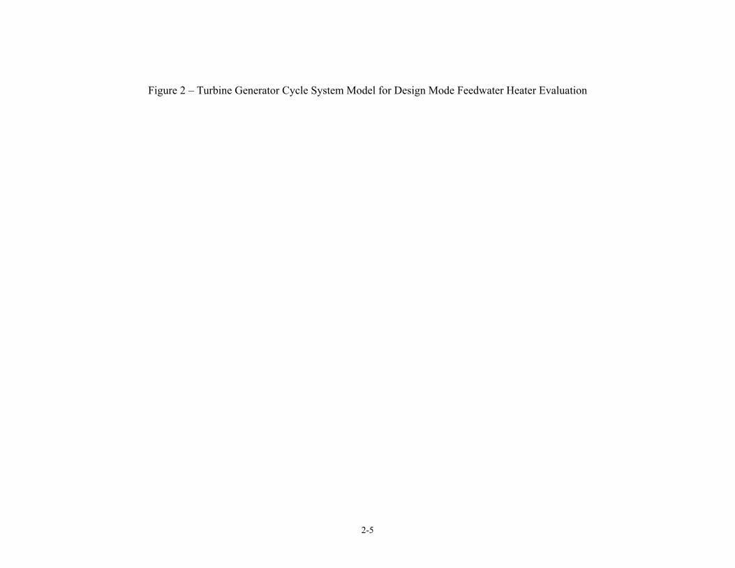
Figure 2 – Turbine Generator Cycle System Model for Design Mode Feedwater Heater Evaluation
2-6
In this system there are four feedwater heaters for which operational variations are being considered. These are the HP heaters, components with ID’s = 300, 310, 320, and 330, lower left corner of the schematic. The variations to be considered are combinations of “A” and “B” string in and out of service. These variations involve substantial changes of flows and statepoints entering the heaters. At these widely varying conditions, the TTD and the DCA are not directly available. These are the simplest parameters that would normally be used to describe the heaters. In their absence, the design mode gives a method to account for these variations. The Objective of the Tuning In a high percentage of cases, the intent of feedwater heater analyses is to evaluate a heater’s thermal/thermodynamic behavior as it affects the performance of a larger system. It is desired to obtain the most representative or accurate performance description possible for the heater, so that the impact on the system will be accurate. The objective of tuning PEPSE’s design mode calculations is to provide a close match between the thermal/thermodynamic results and known performance for at least one operating condition. Most often the known operating condition information is taken from the vendor’s performance claim. It would be possible, alternatively, to perform the tuning analysis to match measured results of a high quality test. Most often, the specific objective of the tuning is to match the TTD (terminal temperature difference) and the DCA (drain cooler approach), if applicable, at the conditions in the available data. Alternatively, the tuning could be performed to match the tube-side outlet temperature and the shell side outlet thermodynamic quality, the latter being equivalent to TTD and DCA. The Simple Method of Tuning In the first method, the TTD and DCA are matched in the easiest way possible, without concern for other internal details and without concern about pressures. The TTD and DCA are directly related to zonal rates of heat transfer in the heater. The matching is accomplished by direct adjustment of heat transfer coefficient multipliers in two of the three zones of the heater. Conceptually the method affects the zonal computation of heat transfer in the basic equation: Q = U * A * LMTD * Multiplier Where Q = zonal rate of heat transfer U = zonal heat conductance (per unit area and temperature difference) A = zonal effective heat transfer surface area LMTD = log mean temperature difference for the zone Multiplier = the zonal tuning factor in question
2-7
There is no guarantee that this method will match, or even come close to, the heat transfer coefficients or zonal heat transfer rates that are reported on the vendor’s specification sheet. Only the TTD and the DCA are matched. Specifically, the TTD is matched by adjustment of the tuning multiplier in the condensing zone, and the DCA is matched by adjustment of the tuning multiplier in the drain cooling zone. Operationally, this adjustment is obtained in PEPSE via two controls. For the example submodel shown in Figure 1 above, the following tables show the completed graphical input forms for these controls. The forms of Table 1 and 1A show use of the heat transfer coefficient variable UALLDC in order to match the vendor’s specified DCA. In order to use UALLDC as a multiplier (tuning factor), it must have a minus sign that serves as a flag. Table 1A shows use of limits, XCLO and XCHI, that are specified to constrain UALLDC to negative values. The initial value of UALLDC is set equal to –1.0 elsewhere in input.
Table 1 – Input Form for DCA Control in Simple Tuning Method
2-8
Table 1A - Input Form Showing Control Variable Limits for First Control in Simple Tuning Method
2-9
The forms of Table 2 and 2A show use of the heat transfer coefficient variable UALLC in order to match the vendor’s specified TTD. In order to use UALLC as a multiplier (tuning factor), it must have a minus sign that serves as a flag. Table 2A shows use of limits, XCLO and XCHI, that are specified to constrain UALLC to negative values. The initial value of UALLC is set equal to –1.0 elsewhere in input.
Table 2 - Input Form for TTD Control in Simple Tuning Method
2-10
Table 2A - Input Form Showing Control Variable Limits for Second Control in Simple Tuning Method
Note that PEPSE’s basic design mode computations automatically include calculations of pressure drops in the heater. In the simple method, no extra effort is expended to produce a match between the computed results and the “known” pressures. The Detailed Method of Tuning The detailed method of tuning the calculations for the design mode feedwater heater takes maximum advantage of the information provided on the vendor’s specification sheet and performance summary. Specifically, the following quantities are matched:
- pressure drops, where given, both shell and tube sides - heat transfer coefficients - TTD (or tube outlet temperature) - DCA (or drain outlet temperature/quality) - heat transfer quantity, where possible
2-11
The parameters that are used for these tunings are:
- shell inlet form loss coefficient, SHKIN - desuperheating zone hydraulic bypass factor, BPFDS - drain cooling zone hydraulic bypass factor, BPFDC - tube side inside relative roughness, RFNC or tube out form loss coefficient,
TUBOUT - desuperheating zone thermal bypass factor, BPHDS - drain cooling zone thermal bypass factor, BPHDC - condensing zone heat transfer coefficient multiplier, UALLC - desuperheating zone heat transfer coefficient multiplier, UALLDS - drain cooling zone heat transfer coefficient multiplier, UALLDC
These tunings are done using controls. Additional explanations, along with example graphics data forms for the controls, are shown as tables in Appendix A. Two cases are used for this tuning work. When viewing these forms, take careful note of the top line that shows the “set” number for each control. In this application, the set 1 provides data for the first case, and the set 2 provides data for the second case. A two-case or two-step tuning run is needed in order to accomplish the tunings. In the first case the desuperheating and drain cooling zones’ heat transfer coefficients have been specified explicitly, as given by the vendor, in order to compute the thermal bypass factors for these zones. In order to pass the tuning factor results of the first case to the second case, the “SAVE” case separator has been used between the cases in setup of the run menu. See Table 3 below. In the second case heat transfer coefficient multipliers are tuned while heat transfer coefficients are left to be calculated from PEPSE’s correlations.
2-12
Table 3 – Run Form Showing Use of “Save case” Separator
These heat transfer coefficients are entered into data via variables UALLDS and UALLDC. At completion of this first step, the results are saved (via the save case terminator), and a second, stacked, case is executed. In the second case controls are introduced to adjust the heat transfer heat transfer coefficient multipliers to match the TTD and DCA. Appendix B shows a .job file that provides a comprehensive summary of all data for the example heater-tuning model. This file shows manipulations of the “delete” feature that are used to phase controls, special inputs, etc into and out of action in the two cases. Note that the thermally related controls in the first case are “deleted” in the second case, and new thermally related controls are introduced. The hydraulically related controls that are used in the first case, generally, are retained for use in the second case. In Appendix B notice the use of special inputs to specify initial values of the controls’ x variables in each of the two stacked cases.
2-13
Results – Application to Actual Feedwater Heater Submodel and Turbine Cycle Model The figure below shows an example of results from tuning to match the TTD and DCA on the vendor’s performance summary for the number 6B heater (component 330) in the system model discussed above.
Figure 3 – Example Tuning Results for Heater 6B, Simple Method The figure below shows a schematic presentation of the example submodel with all of the tuning factors included, as computed using the detailed tuning method.
2-14
Figure 4 – Example Tuning Results for Heater 6B, Detailed Method In order to see the effect of these feedwater heaters in a turbine cycle, the tuned descriptions were transferred into two separate model files for the model of Figure 2. One turbine model file used the heaters tuned by the simple method, and the second used the heaters tuned by the detailed method. The conditions that enter the heater components in these models differ from conditions on the vendor’s specification sheets. Thus, the heater performance should be expected to differ from the tuning cases in the submodels. As a means of comparing the effect of the simple versus the detailed tuning methods, several cases were run on these turbine cycle models with various combinations of the “A” and “B” strings in and out of service. Variations of main steam flow (load) could have been considered also, but they were not. Table 4 below shows a summary of the system results as calculated using the two different turbine cycle models containing the heaters tuned by the two different methods. Appendix D contains schematics for the turbine generator cycle system including display of the results for the four cases that were run using the tuned design mode feedwater heaters.
2-15
Table 4 – System Results for Operations with Several Combinations of Operation of HP Feedwater Heaters
Simple Tuning Method Results Case MW Heat Rate 1S - Both A and B Strings In Service 222.8 81322S - A String in Service, B String Out of Service 225.8 81513S - A String Out of Service, B String In Service 223.7 81424S - Both A and B Strings Out of Service 252.5 8244 Detailed Tuning Method Results 1D - Both A and B Strings In Service 222.8 81322D - A String in Service, B String Out of Service 225.2 81483D - A String Out of Service, B String In Service 224.2 81464D - Both A and B Strings Out of Service 252.5 8244 Discussion of Results The feedwater heater tuning results shown in the section above are reasonable, for the most part. As seen in Figures 3 and 4, in general we expect tuning factors to be approximately 1.0, or perhaps less than 1.0. In order to obtain these results, some judgment actions were made, in respect to baffle spacing, baffle window area, and others. These and others are often necessitated by absence of explicit information on vendors’ specification sheets. See Appendix C for a discussion of some relevant points. Clearly, if different judgments had been made on some or all of these points, the exact values of the tuning factors from the analyses would have been somewhat different. We can conclude that the tuning factors must absorb the effects of many uncertainties. Such uncertainties may include:
- potential differences between the formulations used for hydraulic and thermal computations used by the vendor and by PEPSE,
- assumptions that had to be made in order to perform the analysis at all due to key information missing from vendor sheets,
- differences between the bases of the published hydraulic and thermal correlations and those that would apply to just feedwater heaters, and
- potentially others. In Table 4 above, comparison of the generation and heat rate results for the turbine cycle model reveals an effect of the method of tuning the heater calculations. As seen in Table 4, there is notable difference between the results for the heaters as tuned by the simple and the detailed methods. Notice that for cases 1S and 1D, the first case analyzed by the two methods, the generation and heat rate are the same. Two additional specific cases are
2-16
of interest, 2 and 3 – 2 with only the “A” string of heaters in service and 3 with only the “B” string of heaters in service. Comparing the calculated generations for these two cases shows about 1 mW difference between 2D and 3D when the heaters have been tuned by the detailed method and about 2.1 MW difference between 2S and 3S when the heaters have been tuned by the simple tuning method. Therefore, for the two methods, there is a 1.1 MW (0.5% of generation) discrepancy of the incremental generation between the case with the “A” string in service and case with the “B” string in service. It should be expected that the system results (generation, heat rate, and all other local-component results as well) would be exactly the same for the simple method and for the detailed method when both heater strings are out of service. The table shows that this is the case. The information presented in this paper does not prove that the detailed method gives more accurate predictions of performance than the simple method for varying operating conditions. However, we can make a reasonable argument that matching more details that are known should be better than matching only one or two. The detailed method requires somewhat more labor in its use, but use of PEPSE’s advanced tools for transferring information from one model to another renders the labor difference relatively minor. Summary Two methods of tuning design mode feedwater heaters have been described and demonstrated. Applications of these methods for a representative model show some differences of results. Conclusions The simple method of tuning is easier and quicker to use. It matches only the heater’s TTD and DCA. The detailed method of tuning requires more labor, but the use of external files to transfer data from one model to another can significantly reduce the labor and the chance of error. Because the detailed method matches considerably more of the information provided by the heater vendor, we can suppose that it provides more accurate results over a range of operation of the heater. The results from the system model using the heater descriptions, as tuned by the two different methods, show that there is a difference between the results that are obtained for the system’s performance. Reference D. R. Fleming, et al, “PEPSE and PEPSE-GT Volume 1, Use Input Description”, representing version 67 and GT6.0 of PEPSE, SCIENTECH, Inc, July, 2002.
2-17
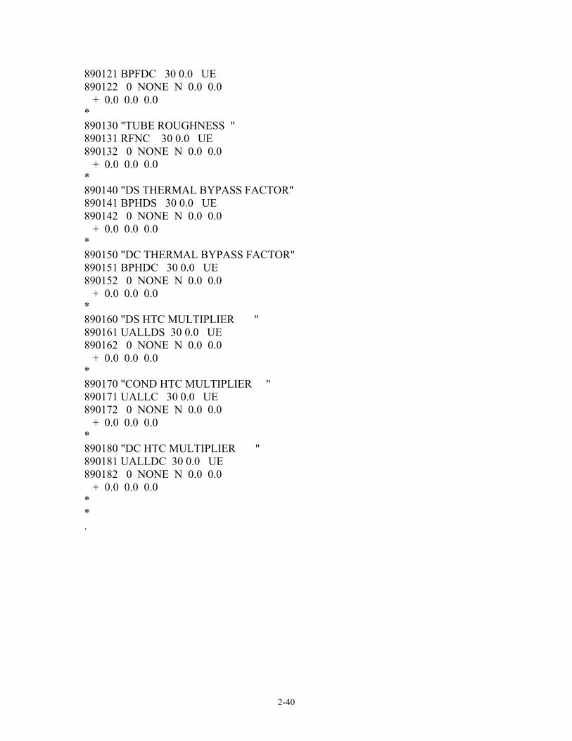
Appendix A – Forms for Controls Used in Detailed Method This appendix contains the completed forms for the controls that were used for tuning the calculations for the “6B” heater, component 330 in the turbine cycle model. Note that a common “template” submodel was used for tuning the four HP heaters. Copies of the submodel were made for each one of the heaters. In these submodels, component ID 30 was used consistently throughout for each one of the heaters. Notice the set numbers on the forms. There were two cases used in the detailed tuning method. These forms implement the procedures described in The Detailed Method of Tuning section above. In the first case (a “save case”): In case 1, control:
- condensing zone’s tube roughness for tube-side pressure drop, - desuperheating zone’s hydraulic bypass factor for zone’s shell-side pressure
drop - drain cooler zone’s hydraulic bypass factor for zone’s shell-side pressure drop - drain cooler zone’s thermal bypass factor for DCA - desuperheating zone’s thermal bypass factor for TTD - condensing zone’s heat transfer coefficient multiplier for condensing zone
heat transfer coefficient In case 2, control:
- drain cooler zone’s heat transfer coefficient variable for DCA - desuperheating zone’s heat transfer coefficient variable for TTD
FORMS FOR CONTROLS IN THE DETAILED TUNING METHOD, CASE 1 The forms of Tables A1 and A1A below show use of the condensing zone’s tube inside roughness variable RFNC in order to match the vendor’s specified tube-side pressure drop. This is 1.0*PP(stream 20 end) – 1.0*PP(stream 30 start), the pressure at the tube inlet minus the pressure at the tube outlet. PEPSE’s input provides for specification of the tube roughness in the desuperheating and drain cooling zones as well. It would make the most sense to have the values equal in all three zones. This can be accomplished by writing operations to equate those in the desuperheating and drain cooling zone to RFNC, the value calculated by the control for the condensing zone. The initial value of RFNC is set equal to 0.001 elsewhere in input. In order to keep the roughness within physically realistic limits, the XCLO and XCHI limits are specified, as shown in Table A1A. You should be aware that if these limits prevent the control from converging, you may need to take an alternative approach to match the vendor’s pressure drop. One possibility would be the tube side inlet or exit nozzle form loss coefficient, variable TUBIN or TUBOUT.
2-18
Table A1 – Input Form for DCA Control in Detailed Tuning Method
2-19
Table A1A – Input Form Showing Control Variable Limits for Tube Roughness
2-20
The forms of Tables A2 and A2A below show use of the desuperheating zone’s hydraulic bypass factor variable BPFDS in order to match the vendor’s specified shell-side pressure drop in the desuperheating zone. The variable names are found in the PEPSE Volume 1 Supplemental Manual, Appendix E. This is 1.0*PB1(30) – 1.0*PB2(30), the shell-side pressure at the zonal inlet minus the pressure at the zonal outlet. In order to keep the bypass factor within physically realistic limits, the XCLO and XCHI limits are specified, as shown in Table A2A. The initial value of BPFDS is set equal to 1.0 elsewhere in input.
Table A2 – Input Form for Control to Obtain Shell-Side Desuperheating Zone Pressure Drop in Detailed Tuning Method
2-21
Table A2A – Input Form Showing Control Variable Limits for Hydraulic Bypass Factor
2-22
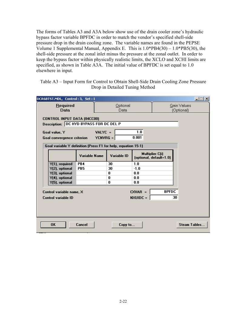
The forms of Tables A3 and A3A below show use of the drain cooler zone’s hydraulic bypass factor variable BPFDC in order to match the vendor’s specified shell-side pressure drop in the drain cooling zone. The variable names are found in the PEPSE Volume 1 Supplemental Manual, Appendix E. This is 1.0*PB4(30) – 1.0*PB5(30), the shell-side pressure at the zonal inlet minus the pressure at the zonal outlet. In order to keep the bypass factor within physically realistic limits, the XCLO and XCHI limits are specified, as shown in Table A3A. The initial value of BPFDC is set equal to 1.0 elsewhere in input.
Table A3 – Input Form for Control to Obtain Shell-Side Drain Cooling Zone Pressure Drop in Detailed Tuning Method
2-23
Table A3A – Input Form Showing Control Variable Limits for Hydraulic Bypass Factor
2-24
The forms of Tables A4 and A4A below show use of the drain cooler zone’s thermal bypass factor variable BPHDC in order to match the vendor’s specified DCA. The DCAOUT variable name is found in the PEPSE Volume 1 Supplemental Manual, Appendix E. In order to keep the bypass factor within physically realistic limits, the XCLO and XCHI limits are specified, as shown in Table A4A. The initial value of BPHDC is set equal to 1.0 elsewhere in input.
Table A4 – Input Form for Control to DCA in Detailed Tuning Method
2-25
Table A4A – Input Form Showing Control Variable Limits for Thermal Bypass Factor
2-26
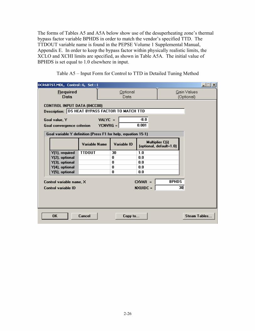
The forms of Tables A5 and A5A below show use of the desuperheating zone’s thermal bypass factor variable BPHDS in order to match the vendor’s specified TTD. The TTDOUT variable name is found in the PEPSE Volume 1 Supplemental Manual, Appendix E. In order to keep the bypass factor within physically realistic limits, the XCLO and XCHI limits are specified, as shown in Table A5A. The initial value of BPHDS is set equal to 1.0 elsewhere in input.
Table A5 – Input Form for Control to TTD in Detailed Tuning Method
2-27
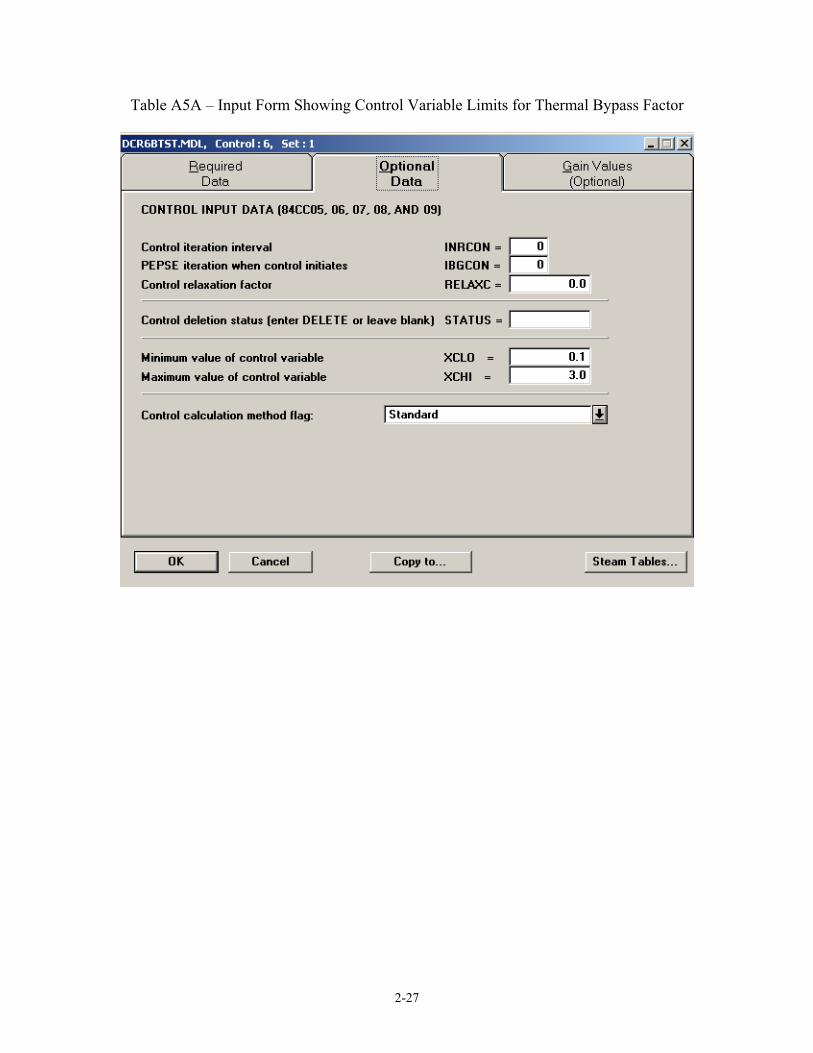
Table A5A – Input Form Showing Control Variable Limits for Thermal Bypass Factor
2-28
The forms of Tables A6 and A6A below show use of the condensing zone’s heat transfer coefficient variable UALLC in order to match the vendor’s specified heat transfer coefficient for the condensing zone. In order to use UALLC as a multiplier (tuning factor), it must have a minus sign that serves as a flag. Table A6A shows use of limits, XCLO and XCHI, that are specified to constrain UALLC to negative values. The initial value of UALLC is set equal to -1.0 elsewhere in input. The UOVRA2 variable name is found in the PEPSE Volume 1 Supplemental Manual, Appendix E.
Table A6 – Input Form for Control to Condensing Zone Heat Transfer Coefficient in Detailed Tuning Method
2-29
Table A6A – Input Form Showing Control Variable Limits for Condensing Zone Heat Transfer Coefficient Multiplier
2-30
FORMS FOR CONTROLS IN THE DETAILED TUNING METHOD, CASE 2 The forms of Tables A7 and A7A below show use of the drain cooler zone’s heat transfer coefficient variable UALLDC in order to match the vendor’s DCA. In order to use UALLDC as a multiplier (tuning factor), it must have a minus sign that serves as a flag. Table A7A shows use of limits, XCLO and XCHI, that are specified to constrain UALLDC to negative values. The initial value of UALLDC is set equal to -1.0 elsewhere in input. The DCAOUT variable name is found in the PEPSE Volume 1 Supplemental Manual, Appendix E.
Table A7 – Input Form for Control to Drain Cooling Zone Heat Transfer Coefficient in Detailed Tuning Method
2-31
Table A7A – Input Form Showing Control Variable Limits for Drain Cooling Zone Heat Transfer Coefficient Multiplier
2-32
The forms of Tables A8 and A8A below show use of the desuperheating zone’s heat transfer coefficient variable UALLDS in order to match the vendor’s TTD. In order to use UALLDS as a multiplier (tuning factor), it must have a minus sign that serves as a flag. Table A8A shows use of limits, XCLO and XCHI, that are specified to constrain UALLDS to negative values. The initial value of UALLDS is set equal to -1.0 elsewhere in input. The TTDOUT variable name is found in the PEPSE Volume 1 Supplemental Manual, Appendix E. Table A8 – Input Form for Control to Desuperheating Zone Heat Transfer Coefficient in
Detailed Tuning Method
2-33
Table A8A – Input Form Showing Control Variable Limits for Desuperheating Zone Heat Transfer Coefficient Multiplier
2-34
Appendix B – Input File for Example Heater Tuning by Detailed Method Table B1 of this appendix contains the .job file for the detailed tuning submodel for the “6B” heater. This file is a comprehensive summary of all of the data needed for the tuning. Interpretation of the file can be made in conjunction with the referenced Volume 1, User’s Manual. Examination of this input file will reveal that control number 4 is inactive in this application. This control would adjust the (pressure) form loss coefficient for the shell side inlet nozzle in order to match the vendor’s value of heat transfer attributed to the condensing zone of the heater. If active, this control would impact the condensing zone’s pressure, thus temperature and therefore impact also the heat transfer rate. Use of this control is a judgment call; it is left in place in this model in order to show how to set up such a control. Since the control is inactive, there are also places elsewhere in the .job file where the variable, SHKIN, has been “deleted”.
Table B1 - .JOB file with Comprehensive Data Summary for Tuning Heater 6B by the Detailed Method
Appendix C – Common Assumptions and Judgments and Transferring Tuning Factors The tuning and use of design mode feedwater heater calculations frequently require assumptions and judgment. For example there is ambiguity about:
- the meaning of “operating pressure” specified on vendor sheets - the amount of pressure drop in the inlet and outlet nozzles re the vendor sheets - the number of baffles (or conversely the baffle spacing) in the desuperheating
and drain cooling zone - the shell-side flow area around the tip of the baffles
Assumptions and Judgments About Baffle Count and Related Topics Vendors rarely give descriptions or basic dimensions of baffles in feedwater heaters. For use in PEPSE’s shell side calculations of pressure drop and heat transfer film coefficient, these descriptions are needed. It is therefore necessary to make assumptions and judgments about baffles. A starting point is a rule of thumb for the baffle window flow area of about 15% of the semi-circular cross sectional area of the heater shell. The number of baffles and the window area are usually obtained by trial and error runs of PEPSE in order to reach reasonable values of the hydraulic bypass factors, as they affect shell side pressure drop. The spacing between the tubes (pitch) in the heaters of this paper was larger than our experience with others. Because of this, it was difficult to obtain pressure drops as high as those shown by the vendor, an unusual problem indeed in our experience. In order to contribute larger shell-side cross-tube pressure drops, some experimentation was done with the number of tubes in crossflow, an optional input specification. Normally this parameter is allowed to default to a value computed by PEPSE from the total number of tubes, a required input. Transferring Data via External Files In the case of the detailed method of tuning, there were a number of tuning parameters for each feedwater heater. Transfer of these values from the submodels to the turbine cycle system model was needed. One option would have been by-hand entry into the data forms for each heater. If this were to be done only once, this would probably have been the least-labor approach. However, there is risk of errors in such data transfers. For this reason, and to provide for the possibility of repeating the tunings (e.g. with new or revised assumptions), PEPSE’s special input and output features were used, together with the use of an external file. The .job file that appears in Appendix B above includes such an external file usage. For purposes of this paper, numerous assumptions were tried, and a significant number of retunings were done in the submodels. The transfer of data via the external file was an extremely useful tool for these repeated runs.
2-42
Fractional Split of the Feedwater Flows when “A” and “B” Are Both in Service In the system being analyzed, the “A” and “B” heater strings were of different eras. The vendor specifications showed notably different pressure drop behaviors on the feedwater side of the heaters between the two sets of specification sheets. The reason for this is unknown. However, these pressure drop behaviors were included in the tuning of the models via the detailed method. In the context of the submodels, this detail is of little consequence. In the system model, we are faced with a choice of what to do about it. If indeed the pressure drops are different, the split of feedwater flow to the “A” and “B” strings should be unequal. It is common in many analyses to assume a 50-50 split to the two trains. In the present case, we could choose to adjust the flow split such that the final feedwater pressures from the “A” string and the “B” string are equal. Such an adjustment is easily set up via a PEPSE control. In this paper, this was not done. Instead, the flow was assumed to split 50-50. This choice was made for consistency in the comparisons between the simple method (where pressure was not considered) and the detailed method of tuning. In a different application where feedwater-side pressure drops are not the same in parallel branches, it would be most accurate to customize the flow split appropriately. Controls In some tuning controls, it is probably beneficial to specify lower and upper bounds for the control variable. This tool can help to confine the value of the control variable to a domain of reasonable values. The controls used in this study included these bounding specifications.
2-43
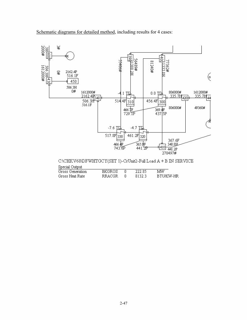
Appendix D – Turbine Generator Model Displays of Results This appendix presents schematic diagrams for the four cases that were run using the tuned design mode feedwater heaters using the simplified and then the detailed method of tuning. The four cases were:
- both trains of heaters in service - only train “A” in service - only train “B” in service - neither train in service
For best readability, the schematics have been cropped to show only the portion of interest involving the “A” and “B” HP heater strings. Notice the title block in each schematic. These provide the description of the cases being shown. Schematic diagrams for simplified method, including results for 4 cases:
2-44
2-45
2-46
2-47
Schematic diagrams for detailed method, including results for 4 cases:


![Microsoft SQL Server Query Tuning - Meetupfiles.meetup.com/1381968/Microsoft SQL Server Query...Microsoft PowerPoint - Microsoft SQL Server Query Tuning [Compatibility Mode] Author](https://static.documents.pub/doc/80x56/5ad9c9447f8b9afc0f8b9e56/microsoft-sql-server-query-tuning-sql-server-querymicrosoft-powerpoint-microsoft.jpg)


