30
M. Ahmad Kamarudin, M. Ha yne, R. J. Young, Q. D. Z huang, T. Ben, and S. I. Molina Tuning the properties of exciton complexes in sel f-assembled GaSb/GaAs qu antum rings
| Date post: | 30-Dec-2015 |
| Category: |
Documents |
| Upload: | kadeem-bell |
| View: | 37 times |
| Download: | 1 times |
M. Ahmad Kamarudin, M. Hayne, R. J. Young, Q. D. Zhuang,
T. Ben, and S. I. Molina
Tuning the properties of exciton complexes in self-assembled
GaSb/GaAs quantum rings

Type-II self-assembled GaSb/GaAs nanostructures have been grown by molecular-beam epitaxy and studied byatomic-force microscopy, transmission electron microscopy, and power-dependent magnetophotoluminescence.Nanostructures on the sample surface are found to be entirely dotlike, while capped nanostructures are predominantly ringlike. Moreover, an in situ anneal process applied after thinly capping the dots is shown to enhance the severity of the rings and relax the strain in the matrix in the proximity of the GaSb, resulting in a change to the spatial configuration of the exciton complexes and their
optical properties.
Outline
• Introduction
• Sample
• Morphology and features
• Experiment
1. zero field photoluminescence
2. magnetophotoluminescence
• Discussion
• Conclusions
Introduction
• GaSb/(Al)GaAs can to extend the absorption spectrum of GaAs solar cells beyond 1 m.
• Provide deep confining potentials capable of room-temperature charge storage for memory applications
Motive
• Compare the differences of GaSb quantum ring by MOCVD and MBE.
1. Morphology
2. Low temperature PL

(a) PL peak transition energy as a function of magnetic field at different laser powers measured at 4.2 K. (b) A depiction of the corresponding electron trajectories represented by solid lines for bound states and dotted lines for free particles asthe sample goes through a density-dependent Mott transition. (c) The values of the exciton radius squares and the exciton binding energy circles as a function of excitation power, obtained from the fits in (a).
PHYSICAL REVIEW B 77, 241304
GaSb/GaAs quantum dot
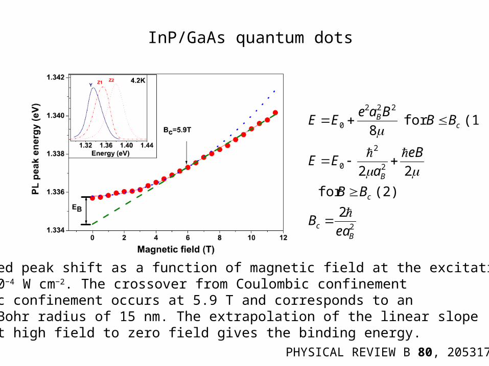
The measured peak shift as a function of magnetic field at the excitation power of about 10−4 W cm−2. The crossover from Coulombic confinementto magnetic confinement occurs at 5.9 T and corresponds to aneffective Bohr radius of 15 nm. The extrapolation of the linear slopemeasured at high field to zero field gives the binding energy.
2
2
2
0
222
0
2
(2) for
22
(1) for 8
Bc
c
B
cB
eaB
BB
eB
aEE
BBBae
EE
InP/GaAs quantum dots
PHYSICAL REVIEW B 80, 205317
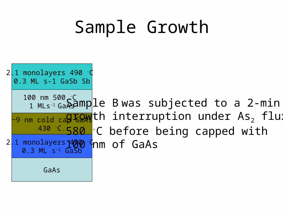
GaAs
2.1 monolayers 490 ◦C 0.3 ML s-1 GaSb
~9 nm cold cap GaAs430 ◦C.
100 nm 500 ◦C 1 MLs-1 GaAs
2.1 monolayers 490 ◦C 0.3 ML s-1 GaSb Sb
Sample Growth
Sample B was subjected to a 2-min growth interruption under As2 flux at 580 ◦C before being capped with 100 nm of GaAs
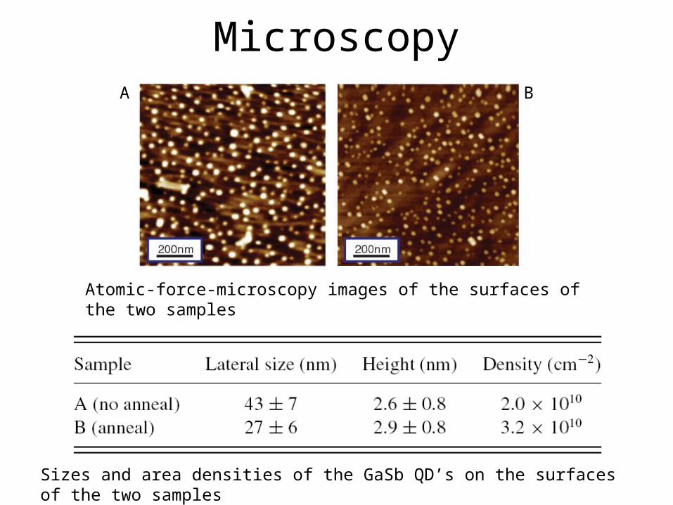
Microscopy
Sizes and area densities of the GaSb QD’s on the surfaces of the two samples
Atomic-force-microscopy images of the surfaces of the two samples
A B
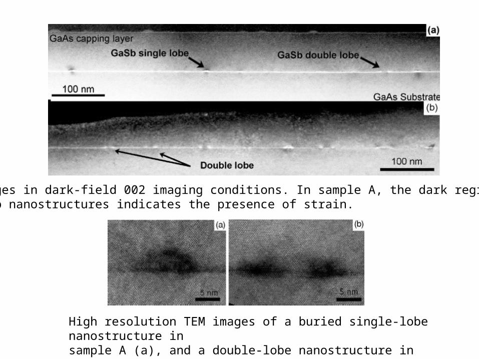
TEM images in dark-field 002 imaging conditions. In sample A, the dark region above the GaSb nanostructures indicates the presence of strain.
High resolution TEM images of a buried single-lobe nanostructure in sample A (a), and a double-lobe nanostructure in sample B (b).

The dissolution effect of capping the nanostructures
LOW-TEMPERATUREMAGNETOPHOTOLUMINESCENCE
• Low-temperature (≦ 4.2 K)
• Frequency-doubled diode-pumped solid-state laser (532 nm)
• 30-cm focal length spectrometer was combined with a Peltier-cooled InGaAs diode array
• Spot diameter on the sample was 2 mm∼

Low-temperature photoluminescence (PL) data at zero magnetic fieldSample A (no anneal) is in blue and sample B (anneal) is in red. Spectra: the quantum ring (QR), wetting layer,and GaAs peaks are labeled.

Simplified band diagram showing spatially indirect excitons with electrons in the GaAs matrix and holes in the GaSb valence band of the WL and QD. The z axis denotes the growth direction and the QDs are distributed in the xy plane.
PHYSICAL REVIEW B 77, 241304
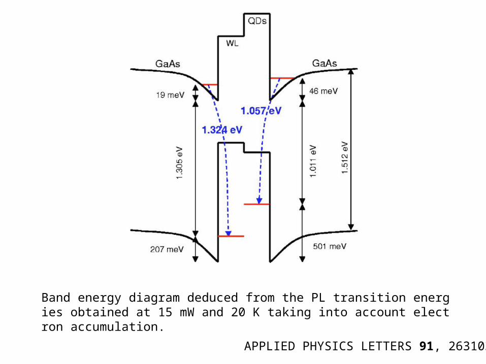
Band energy diagram deduced from the PL transition energies obtained at 15 mW and 20 K taking into account electron accumulation.
APPLIED PHYSICS LETTERS 91, 263103

Explain the difference in emission energy
1. a reduction in QR charging in sample B due to lower unintentional p-doping compared with sample A
2. an increase in the size of the nanostructures in sample B when compared to sample A
3. a change in the composition induced by the different capping conditions for the two samples.

PHYSICAL REVIEW B 70, 081302
At low power photoexcited holes are captured by unoccupied carbon acceptors, C−, while photoexcited electrons recombine with the holes in the dots, reducing the hole population and causing a red shift in the PL. At high laser powers all the carbon acceptors are occupied, so photoexcited holes are rapidly captured by the QD, causing a blue shift in the PL.
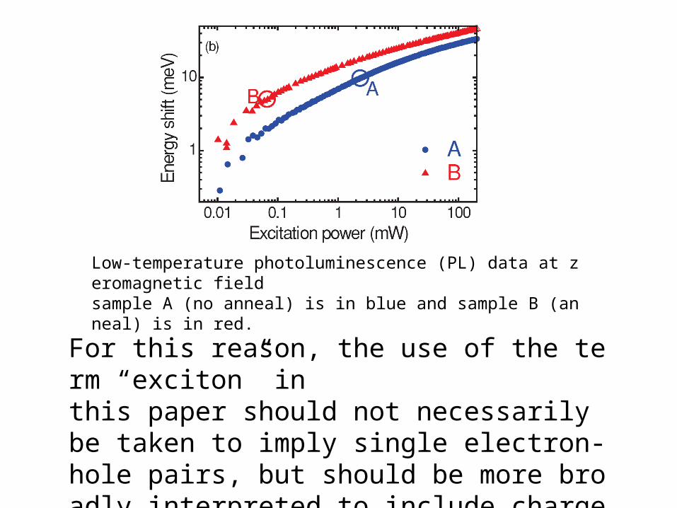
Low-temperature photoluminescence (PL) data at zeromagnetic field sample A (no anneal) is in blue and sample B (anneal) is in red.
For this reason, the use of the term “exciton” inthis paper should not necessarily be taken to imply single electron-hole pairs, but should be more broadly interpreted to include charged excitons and other exciton complexes.
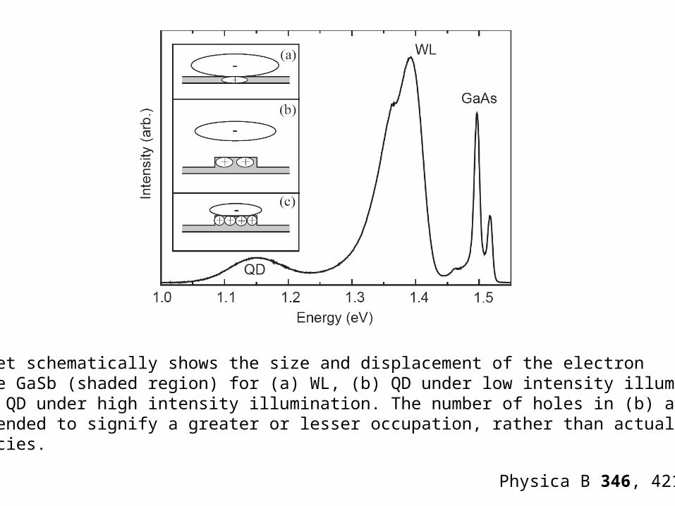
The inset schematically shows the size and displacement of the electronfrom the GaSb (shaded region) for (a) WL, (b) QD under low intensity illumination and (c) QD under high intensity illumination. The number of holes in (b) and (c) are intended to signify a greater or lesser occupation, rather than actualoccupancies.
Physica B 346, 421
2. an increase in the size of the nanostructures in sample B when compared to sample A
• Confinement energies for holes are much less sensitive to size effects than for electrons, and the TEM data indicate no systematic change in QR base length or height between samples A and B
• Because sample B was annealed, the strain in the GaAs close to the quantum rings were smaller than the sample A.
Magnetophotoluminescence
BSr
rAP
B
ee
gμeV
m
eH )(
2
)(*
2
eB m
e
2
BSA
PAAPP
B
eee
e
g
m
e
m
eeV
mH
*
22
**
2
222
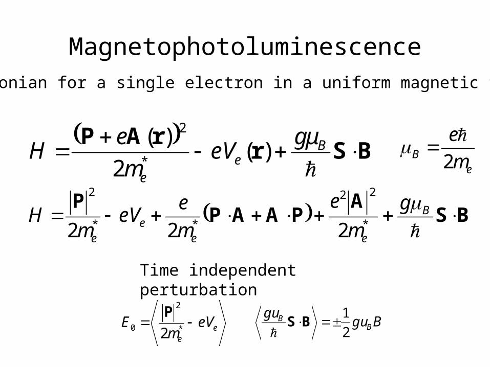
Hamiltonian for a single electron in a uniform magnetic field B
Bgugu
BB
2
1BS
Time independent perturbation
ee
eVm
E *
2
0 2
P

01
222
)(2
1
22
2
)()()(
2
)1(00
0
2
I20
***I
**I
*I
j j
le
Zee
ee
e
EE
jHE
Bmm
eBL
m
e
m
eH
xyBm
e
m
eH
i
ii
m
eH
BL
jiABLPA
PAA
AAAAP
PAAP
)(8
)(4
1
2
2
22*
22222
*
210
*
222
II
xym
BexyB
m
eE
m
eH
ee
e
A
)(2
1A ji xyB
8
222
0 Bae
EE B

22 2
2
0 eB
aEE
B
le
Ze
e
Bmm
eBL
m
e
m
eH
**
*
22
2
BL
2
2
2
2
2
2
22
4
B
Bn
ma
mea
n
meE
electron and hole pair energy level
precession

Quantum-ring PL peak position as a function of magnetic field. The lines are fits to Eqs. (1) and (2). It can be seen that the field-induced shift of the PL is much larger for sample B than sample A, and thatfor sample A the field dependence is highly parabolic at low laserpower (b) and more linear at high laser power (a). For sample B, theopposite trend is observed (d).
2
2
2
0
222
0
2
(2) for
22
(1) for 8
Bc
c
B
cB
eaB
BB
eB
aEE
BBBae
EE
E0 is the zero-field PL energyaB is the exciton Bohr radiusμ is the reduced exciton mass
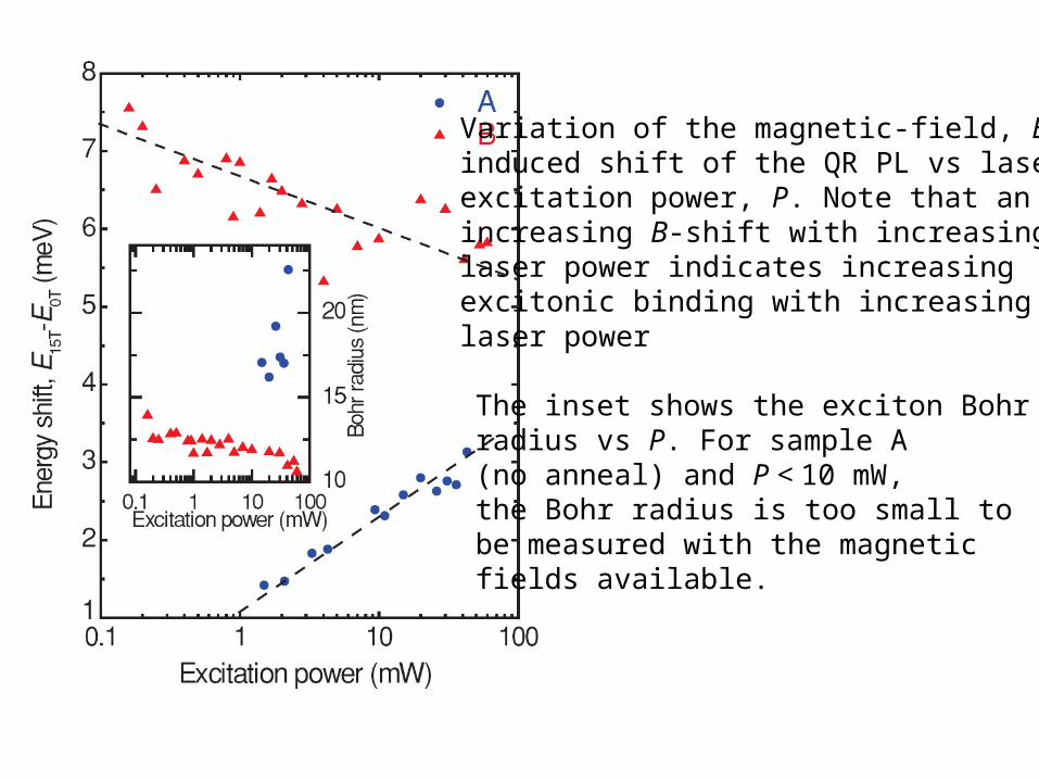
Variation of the magnetic-field, B, induced shift of the QR PL vs laser excitation power, P. Note that an increasing B-shift with increasing laser power indicates increasing excitonic binding with increasing laser power
The inset shows the exciton Bohr radius vs P. For sample A (no anneal) and P < 10 mW, the Bohr radius is too small to be measured with the magnetic fields available.
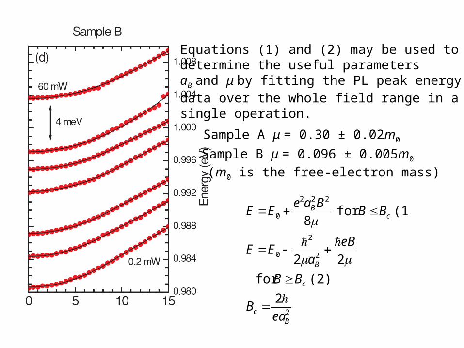
Equations (1) and (2) may be used to determine the useful parameters aB and μ by fitting the PL peak energy data over the whole field range in a single operation.
Sample A μ = 0.30 ± 0.02m0
Sample B μ = 0.096 ± 0.005m0
(m0 is the free-electron mass)
2
2
2
0
222
0
2
(2) for
22
(1) for 8
Bc
c
B
cB
eaB
BB
eB
aEE
BBBae
EE

Discussion
• Sample A (no anneal) has a smaller opening in the center of the QR than sample B, with a higher Sb content.
• Since the electron is weakly bound to the hole in the
QR, when laser power is increased, electron-electron interactions (screening) dominate over electron-hole interactions, resulting in a smearing out of the electron wave function, which increases the B-field shift and Bohr radius
• Sample B (anneal) has a larger opening in the QR with a lower Sb content
• the close proximity of the electron to the QR means that the electron-hole interaction dominates, and as the photoexcited holes charge the QR with increasing laser power, the excitonic binding is increased, not reduced. This decreases the size of the B-field shift and the Bohr radius.
Conclusions
Annealing of the second sample resulted in changes in the ring morphology that effect the spatial configuration of the excitons, leading to quite different optical properties in the two samples.
We hope that this will stimulate further theoretical and experimental work, leading to the observation of AB oscillations in GaSb QR’s in the future.


