Quick Start Guide Tuningless Features for Kinetix 5500 and Kinetix 5700 Servo Drives Kinetix 5500 and Kinetix 5700 Servo Drives Closed-loop servo systems require settings for the control loop gain and filter values to make sure that the load accurately follows the desired input-command signal. The process of adjusting and refining the gain and filter configuration is called tuning. Appropriate tuning settings depend heavily upon the system characteristics. Each machine behaves differently due to variables such as compliance, backlash, changing inertias, manufacturing tolerances, and machine degradation, so the tuning configuration can vary greatly from one machine to the next. With the tuning features of the Kinetix® 5500 and Kinetix 5700 servo drives, tuningless operation can now be achieved without compromising on performance. By using both the load observer and the tracking notch filter in Kinetix 5500 and Kinetix 5700 servo drives, most applications no longer require tuning procedures and tests during the commissioning process to achieve an effective level of machine performance. Summary of Changes This publication contains new and updated information as indicated in the following table. Topic Page Summary of Changes 1 Additional Resources 2 Load Observer 2 Adaptive Tuning with the Tracking Notch Filter 5 Additional Considerations 7 Topic Page Added information about the Load Observer with Velocity Estimate option. 4 Added note about selecting additional parameters. 6
Transcript
Quick Start Guide
Tuningless Features for Kinetix 5500 andKinetix 5700 Servo DrivesKinetix 5500 and Kinetix 5700 Servo Drives
Closed-loop servo systems require settings for the control loop gain and filter values to make sure that the load accurately follows the desired input-command signal. The process of adjusting and refining the gain and filter configuration is called tuning.
Appropriate tuning settings depend heavily upon the system characteristics. Each machine behaves differently due to variables such as compliance, backlash, changing inertias, manufacturing tolerances, and machine degradation, so the tuning configuration can vary greatly from one machine to the next.
With the tuning features of the Kinetix® 5500 and Kinetix 5700 servo drives, tuningless operation can now be achieved without compromising on performance. By using both the load observer and the tracking notch filter in Kinetix 5500 and Kinetix 5700 servo drives, most applications no longer require tuning procedures and tests during the commissioning process to achieve an effective level of machine performance.
Summary of Changes
This publication contains new and updated information as indicated in the following table.
Topic Page
Summary of Changes 1
Additional Resources 2
Load Observer 2
Adaptive Tuning with the Tracking Notch Filter 5
Additional Considerations 7
Topic Page
Added information about the Load Observer with Velocity Estimate option. 4
Added note about selecting additional parameters. 6
Tuningless Features for Kinetix 5500 and Kinetix 5700 Servo Drives
Additional Resources
These documents contain additional information concerning related products from Rockwell Automation.
You can view or download publications at http://www.rockwellautomation.com/global/literature-library/overview.page. To order paper copies of technical documentation, contact your local Allen-Bradley distributor or Rockwell Automation sales representative.
Load ObserverThe load observer feature operates in real time while the machine is running. During machine operation, the load observer estimates the mechanical load inertia on the motor and compensates for it. The result is that the drive controls the motor as if it is unloaded, which provides a relatively high level of drive performance. In addition, the drive automatically compensates for mechanical variations in the system such as changing loads, compliance, and machine wear over time.
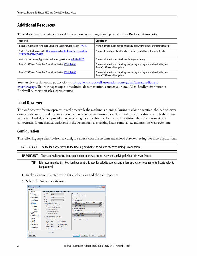
ConfigurationThe following steps describe how to configure an axis with the recommended load observer settings for most applications.
1. In the Controller Organizer, right-click an axis and choose Properties.
2. Select the Autotune category.
Resource Description
Industrial Automation Wiring and Grounding Guidelines, publication 1770-4.1 Provides general guidelines for installing a Rockwell Automation® industrial system.
Tuningless Features for Kinetix 5500 and Kinetix 5700 Servo Drives
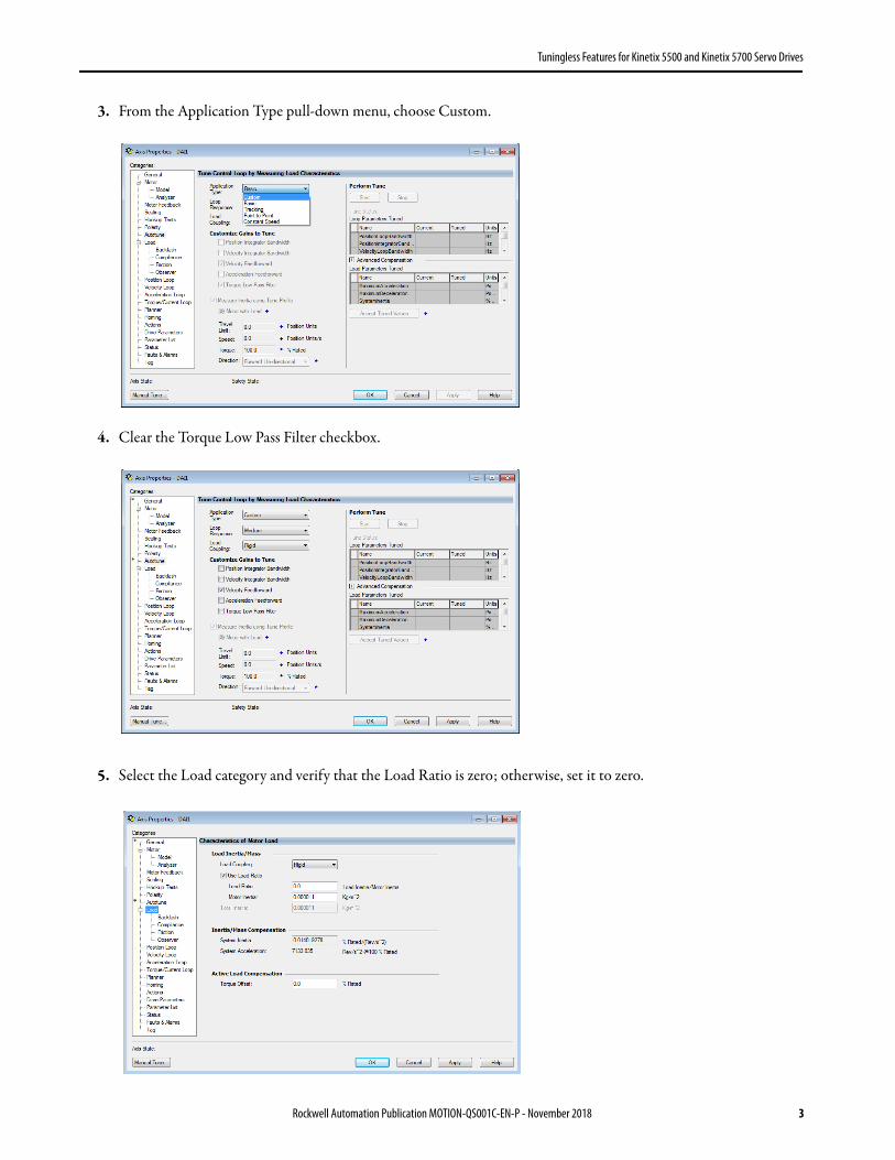
3. From the Application Type pull-down menu, choose Custom.
4. Clear the Torque Low Pass Filter checkbox.
5. Select the Load category and verify that the Load Ratio is zero; otherwise, set it to zero.
Rockwell Automation Publication MOTION-QS001C-EN-P - November 2018 3
Tuningless Features for Kinetix 5500 and Kinetix 5700 Servo Drives
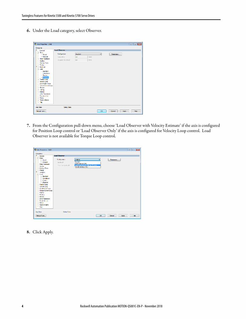
6. Under the Load category, select Observer.
7. From the Configuration pull-down menu, choose ‘Load Observer with Velocity Estimate’ if the axis is configured for Position Loop control or ‘Load Observer Only’ if the axis is configured for Velocity Loop control. Load Observer is not available for Torque Loop control.
8. Click Apply.
4 Rockwell Automation Publication MOTION-QS001C-EN-P - November 2018
Tuningless Features for Kinetix 5500 and Kinetix 5700 Servo Drives
Adaptive Tuning with the Tracking Notch Filter
The tracking notch filter operates in real time while the machine runs. During machine operation, the drive measures the mechanical resonances in the system and dynamically sets the notch filter frequency to mitigate the resonances.
Configuration
The following steps describe how to configure an axis with the recommended adaptive-tuning settings for most applications.
1. In the Controller Organizer, right-click an axis and then choose Properties.
2. Under the Load category, select Compliance.
3. From the Adaptive Tuning Configuration pull-down menu, choose Tracking Notch.
IMPORTANT The load observer and the tracking notch filter should be used in conjunction to achieve effective tuningless operation.
Rockwell Automation Publication MOTION-QS001C-EN-P - November 2018 5
Tuningless Features for Kinetix 5500 and Kinetix 5700 Servo Drives
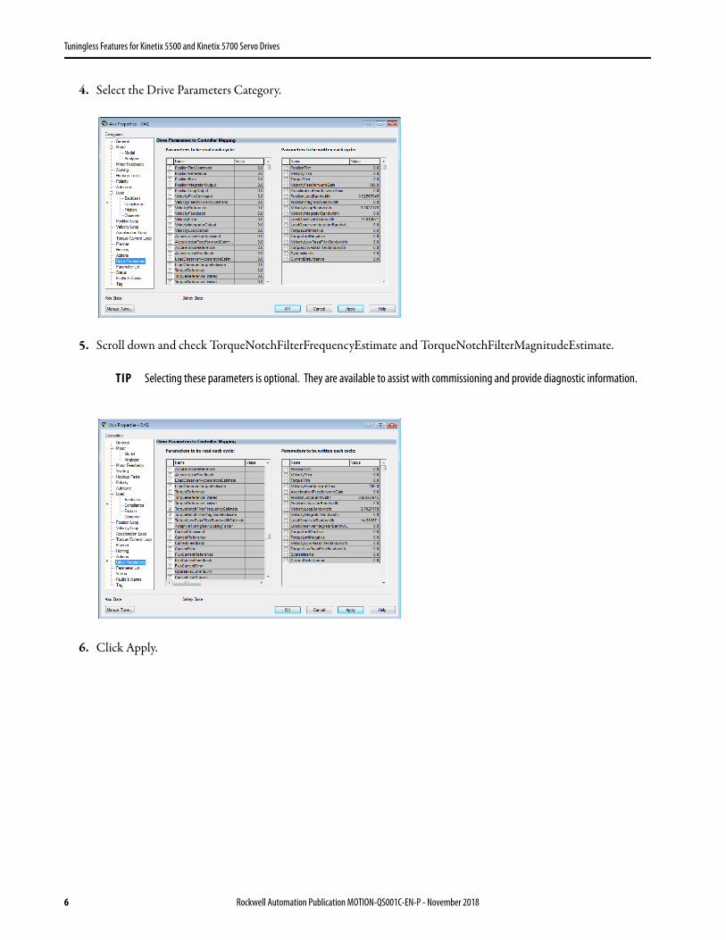
4. Select the Drive Parameters Category.
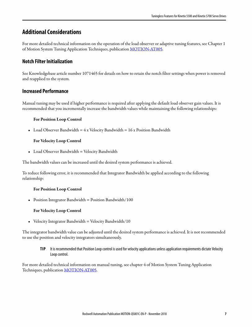
5. Scroll down and check TorqueNotchFilterFrequencyEstimate and TorqueNotchFilterMagnitudeEstimate.
6. Click Apply.
TIP Selecting these parameters is optional. They are available to assist with commissioning and provide diagnostic information.
6 Rockwell Automation Publication MOTION-QS001C-EN-P - November 2018
Tuningless Features for Kinetix 5500 and Kinetix 5700 Servo Drives
Additional Considerations
For more detailed technical information on the operation of the load observer or adaptive tuning features, see Chapter 1 of Motion System Tuning Application Techniques, publication MOTION-AT005.
Notch Filter Initialization
See Knowledgebase article number 1071465 for details on how to retain the notch filter settings when power is removed and reapplied to the system.
Increased Performance
Manual tuning may be used if higher performance is required after applying the default load observer gain values. It is recommended that you incrementally increase the bandwidth values while maintaining the following relationships:
For Position Loop Control
• Load Observer Bandwidth = 4 x Velocity Bandwidth = 16 x Position Bandwidth
For Velocity Loop Control
• Load Observer Bandwidth = Velocity Bandwidth
The bandwidth values can be increased until the desired system performance is achieved.
To reduce following error, it is recommended that Integrator Bandwidth be applied according to the following relationship:
For Position Loop Control
• Position Integrator Bandwidth = Position Bandwidth/100
The integrator bandwidth value can be adjusted until the desired system performance is achieved. It is not recommended to use the position and velocity integrators simultaneously.
For more detailed technical information on manual tuning, see chapter 4 of Motion System Tuning Application Techniques, publication MOTION-AT005.
TIP It is recommended that Position Loop control is used for velocity applications unless application requirements dictate Velocity Loop control.
Rockwell Automation Publication MOTION-QS001C-EN-P - November 2018 7
Tuningless Features for Kinetix 5500 and Kinetix 5700 Servo Drives
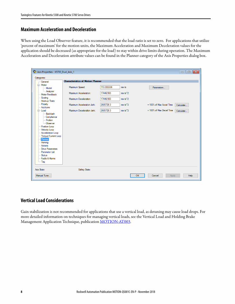
Maximum Acceleration and Deceleration
When using the Load Observer feature, it is recommended that the load ratio is set to zero. For applications that utilize ‘percent of maximum’ for the motion units, the Maximum Acceleration and Maximum Deceleration values for the application should be decreased (as appropriate for the load) to stay within drive limits during operation. The Maximum Acceleration and Deceleration attribute values can be found in the Planner category of the Axis Properties dialog box.
Vertical Load Considerations
Gain stabilization is not recommended for applications that use a vertical load, as detuning may cause load drops. For more detailed information on techniques for managing vertical loads, see the Vertical Load and Holding Brake Management Application Technique, publication MOTION-AT003.
8 Rockwell Automation Publication MOTION-QS001C-EN-P - November 2018
Tuningless Features for Kinetix 5500 and Kinetix 5700 Servo Drives
Notes:
Rockwell Automation Publication MOTION-QS001C-EN-P - November 2018 9
Allen-Bradley, Kinetix, LISTEN. THINK. SOLVE., Rockwell Automation, and Rockwell Software are trademarks of Rockwell Automation, Inc.Trademarks not belonging to Rockwell Automation are property of their respective companies.
Publication MOTION-QS001C-EN-P - November 2018
Rockwell Otomasyon Ticaret A.Ş., Kar Plaza İş Merkezi E Blok Kat:6 34752 İçerenköy, İstanbul, Tel: +90 (216) 5698400
Rockwell Automation maintains current product environmental information on its website at http://www.rockwellautomation.com/rockwellautomation/about-us/sustainability-ethics/product-environmental-compliance.page.
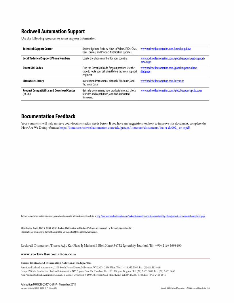
Rockwell Automation SupportUse the following resources to access support information.
Documentation FeedbackYour comments will help us serve your documentation needs better. If you have any suggestions on how to improve this document, complete the How Are We Doing? form at http://literature.rockwellautomation.com/idc/groups/literature/documents/du/ra-du002_-en-e.pdf.
Technical Support Center Knowledgebase Articles, How-to Videos, FAQs, Chat, User Forums, and Product Notification Updates.
www.rockwellautomation.com/knowledgebase
Local Technical Support Phone Numbers Locate the phone number for your country. www.rockwellautomation.com/global/support/get-support-now.page
Direct Dial Codes Find the Direct Dial Code for your product. Use the code to route your call directly to a technical support engineer.