Manual Number 920708-3 Rev. C 09/04 Industrial Grade TURBINE HOUSING Owner’s Manual Includes Aluminum, Brass and Stainless Steel Housings and ANSI Flange Fittings 5252 East 36th Street North Wichita, KS USA 67220-3205 TEL: 316-686-7361 FAX: 316-686-6746 “A Great Plains Ventures Subsidiary” www.gpi.net 1-888-996-3837
Transcript
Manual Number 920708-3 Rev. C
09/04
Industrial Grade
TURBINE HOUSINGOwner’s ManualIncludes Aluminum, Brass and Stainless SteelHousings and ANSI Flange Fittings
5252 East 36th Street NorthWichita, KS USA 67220-3205TEL: 316-686-7361FAX: 316-686-6746
“A Great P la ins Ventures Subsid iary”
www.gpi.net
1-888-996-3837
2
To the owner…
Congratulations on receiving your GPIIndustrial Grade Turbine. We are pleased toprovide you with a product designed to giveyou maximum reliability and efficiency.
Our business is the design, manufacture,and marketing of liquid handling, agricul-tural, and recreational products. We succeedbecause we provide customers with innova-tive, reliable, safe, timely, and competitively-priced products. We pride ourselves in con-ducting our business with integrity and pro-fessionalism.
We are proud to provide you with aquality product and the support you need toobtain years of safe, dependable service.
PresidentGreat Plains Industries, Inc.
GENERAL INFORMATION
General Information ................................... 2
Illustrated Parts Drawing ......................... 16
Service ...................................................... 18
TABLE OF CONTENTS
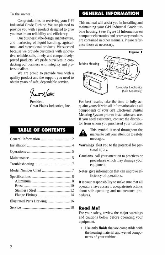
Figure 1
Turbine Housing
Computer Electronics(Sold Separately)
This manual will assist you in installing andmaintaining your GPI Industrial Grade tur-bine housing. (See Figure 1) Information oncomputer electronics and accessory modulesare contained in other manuals. Please refer-ence those as necessary.
For best results, take the time to fully ac-quaint yourself with all information about allcomponents of your GPI Electronic DigitalMetering System prior to installation and use.If you need assistance, contact the distribu-tor from whom you purchased your turbine.
This symbol is used throughout themanual to call your attention to safetymessages.
Warnings alert you to the potential for per-sonal injury.
Cautions call your attention to practices orprocedures which may damage yourequipment.
Notes give information that can improve ef-ficiency of operations.
It is your responsibility to make sure that alloperators have access to adequate instructionsabout safe operating and maintenance pro-cedures.
Read Me!For your safety, review the major warningsand cautions below before operating yourequipment.
1. Use only fluids that are compatible withthe housing material and wetted compo-nents of your turbine.
2. When measuring flammable liquids, ob-serve precautions against fire or explo-sion.
3. When handling hazardous liquids, al-ways follow the liquid manufacturer’ssafety precautions.
4. When working in hazardous environ-ments, always exercise appropriatesafety precautions.
5. Always dispose of used cleaning solventsin a safe manner according to the sol-vent manufacturer’s instructions.
6. During turbine removal, liquid may spill.Follow the liquid manufacturer’s safetyprecautions for clean up of minor spills.
7. Do not blow compressed air through theturbine.
8. Do not allow liquids to dry inside theturbine.
9. Handle the rotor carefully. Even smallscratches or nicks can affect accuracy.
10. When tightening the turbine, use awrench only on the wrench flats.
11. For best results, always verify accuracybefore use.
Product DescriptionGPI Industrial Meter Turbines are identi-fied by the internal diameter of the inlet andoutlet.
Each turbine is designed to work with on-board computer electronics and/or with oneof several accessory output modules.
Liquid flows through the turbine housingcausing an internal rotor to spin. As the rotorspins, an electrical signal is generated in thepickup coil. This signal is converted into en-gineering units (gallons, litres, etc.) on thelocal display. Accessory modules can be usedto export the signal to other equipment.
3
Upon receipt, examine your meter for vis-ible damage. The turbine is a precisionmeasuring instrument and should be handledas such. Remove the protective plugs andcaps for a thorough inspection. If any items aredamaged or missing, contact your distributor.
Make sure the turbine model meets your spe-cific needs. Refer to the Specifications Sec-tion and confirm the following:
✔ The flowrate is within the limits ofyour model.
✔ The liquid is compatible with the tur-bine’s wetted components.
✔ The system’s pressure does not ex-ceed the turbine’s maximum pres-sure rating.
Information specific to your particular tur-bine, including serial number, model num-ber, manufacturing date, and K-factor isetched on the meter. Be prepared to providethis information if you call customer service.
SN = Serial Number, a 6-digit number thatidentifies this particular turbine.
MODEL = Model Number begins with aletter indicating the housing material.
A for AluminumB for BrassH for Stainless Steel High PressureS for Stainless Steel
Two digits follow the material code indicat-ing the size.
The final letter indicates the type of thread.F for FlangeN for NPTI for ISO
MFG DATE = Manufacturing Date indi-cating the week and year of manufacture.
KF = K-Factor given in pulses per gallon(PPG).
For your future reference, it might be usefulto record this information in the manual incase it becomes unreadable on the turbine.
4
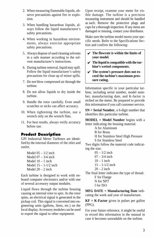
All GPI turbines are designed to measureflow in only one direction. The direction isindicated by the arrow, cast-molded in theturbine. If the computer display is upsidedown, remove the four screws, turn the dis-play 180° and reinstall the screws. See Dia-gram 1.
Downstream from the turbine, allow a mini-mum straight pipe length at least 5 times theinternal diameter of your turbine. For ex-ample, with the 1" turbine, there should be 5inches (12.7cm) of straight pipe immediatelydownstream. The desired downstream dis-tance is 10 inches (25.4cm). See Diagram 3.
INSTALLATION
Diagram 1
Flow altering devices such as elbows, valves,and reducers can affect accuracy. See Dia-gram 2. The following recommended guide-lines are given to enhance accuracy and maxi-mize performance. Distances given here areminimum requirements; double them for de-sired straight pipe lengths.
Diagram 2
Upstream from the turbine, allow a minimumstraight pipe length at least 10 times the in-ternal diameter of the turbine. For example,with the 1" turbine, there should be 10 inches(25.4cm) of straight pipe immediately up-stream. The desired upstream straight pipelength is 20 inches (50.8cm).
Diagram 3
A typical back pressure of 5 to 50 PSI (0.34to 3.4 bar) will prevent cavitation. Createback pressure by installing a control valveon the downstream side of the meter at theproper distance detailed above.
Foreign material in the liquid being measuredcan clog the turbine’s rotor and adverselyaffect accuracy. If this problem is anticipatedor experienced, install screens to filter im-purities from incoming liquids.
To ensure accurate measurement, remove allair from the system before use.
Each turbine contains a removable backcoverplate. Leave the coverplate installedunless accessory modules specify removal.
5
Connections1. To protect against leakage, seal all
threads with an appropriate sealing com-pound. Make sure the sealing compounddoes not intrude into the flow path.
2. Make sure the arrow on the outlet ispointed in the direction of the flow.
3. Tighten the turbine onto the fittings. Usea wrench only on wrench flats.
NOTE: If connecting to new male threads,burrs and curls can adversely effect ac-curacy. Correct the problem prior to tur-bine installation.
Verify accuracy after connections are com-plete. See Operations section.
Flange ConnectionUse a gasket between the meter flange andmating flange. Determine the material of thegasket based on the operating conditions andtype of fluid.
NOTE: Do not over tighten the flange bolts.This may cause the gasket to be com-pressed into the flow stream and maydecrease the accuracy of the meter.
Verify AccuracyBefore use, check the turbine’s accuracy andverify calibration.
1. Make sure there is no air in the system.
2. Measure an exact known volume into anaccurate container.
3. Verify the volume against the readout orrecording equipment.
NOTE: If necessary, use a correction factorto figure final volume.
For best results, accuracy should be verifiedperiodically as part of a routine maintenanceschedule.
! ! ! WARNING ! ! !During turbine removal, liquid may spill.Follow the liquid manufacturer’s safetyprecautions for clean up of minor spills.
OPERATIONS
Remove the Turbine
1. Drain all liquid from the turbine. Wearprotective clothing as necessary.
2. Loosen both ends of the turbine. Use awrench only on the turbine’s wrench flats.
3. If the turbine is not immediately installedagain, cap lines as necessary.
Clean the TurbineDuring use, the turbine should be kept fullof liquid to ensure that drying does not occurinside the turbine. If drying or caking shouldoccur, the rotor will stick or drag, affecting ac-curacy. To determine if the rotor is stuck or drag-ging, gently blow air through the meter andlisten for the quiet whir of the rotor.
CAUTION: Never blow compressed airthrough the meter. It could damage therotor.
1. Remove the turbine from the system fol-lowing the directions above.
2. Carefully clean residue off all parts. Re-move internal parts as detailed above.Note orientation carefully for correctassembly. Internal parts can be soakedfor 10 to 15 minutes in compatible clean-ing solutions. Use a soft brush or smallprobe to carefully remove residue fromthe rotor.
3. When the rotor turns freely, assembleand install it again following the instruc-tions above.
MAINTENANCE
! ! ! WARNING ! ! !Follow the liquid manufacturer’s instruc-tions for the disposal of contaminatedcleaning solvents.
6
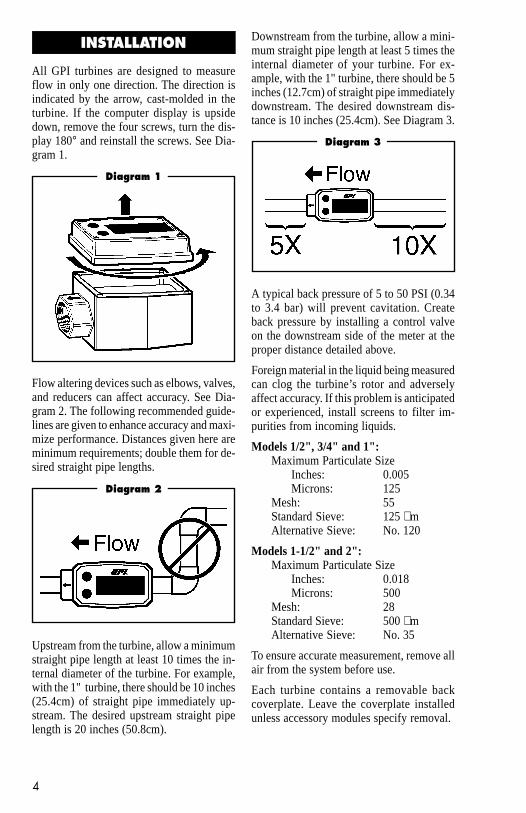
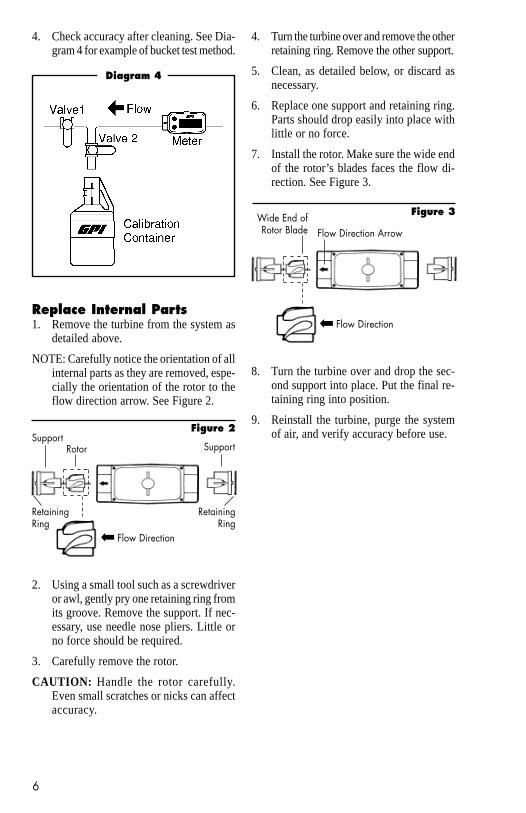
4. Check accuracy after cleaning. See Dia-gram 4 for example of bucket test method.
Replace Internal Parts1. Remove the turbine from the system as
detailed above.
NOTE: Carefully notice the orientation of allinternal parts as they are removed, espe-cially the orientation of the rotor to theflow direction arrow. See Figure 2.
Diagram 4
2. Using a small tool such as a screwdriveror awl, gently pry one retaining ring fromits groove. Remove the support. If nec-essary, use needle nose pliers. Little orno force should be required.
3. Carefully remove the rotor.
CAUTION: Handle the rotor carefully.Even small scratches or nicks can affectaccuracy.
4. Turn the turbine over and remove the otherretaining ring. Remove the other support.
5. Clean, as detailed below, or discard asnecessary.
6. Replace one support and retaining ring.Parts should drop easily into place withlittle or no force.
7. Install the rotor. Make sure the wide endof the rotor’s blades faces the flow di-rection. See Figure 3.
8. Turn the turbine over and drop the sec-ond support into place. Put the final re-taining ring into position.
9. Reinstall the turbine, purge the systemof air, and verify accuracy before use.
Figure 3
Flow Direction ArrowWide End ofRotor Blade
Flow Direction
➡
RotorSupport
RetainingRing
Support
Figure 2
RetainingRing
Flow Direction
➡
Normal Normal Inlet / StainlessRange Range Outlet SteelGPM LPM Size Stainless HighWater Water NPT Aluminum Brass Steel Pressure
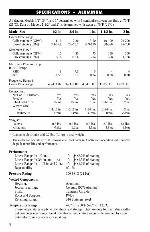
PerformanceLinear Range for 1/2 in.: 10:1 @ ±2.0% of readingLinear Range for 3/4 in. and 1 in.: 10:1 @ ±1.5% of readingLinear Range for 1-1/2 in. and 2 in.: 10:1 @ ±1.0% of readingRepeatability: ±0.1%
Temperature Range -40° to +250°F (-40° to +121°C)These temperatures apply to operations and storage. They are only for the turbine with-out computer electronics. Final operational temperature range is determined by com-puter electronics or accessory modules.
Model Size 1/2 in. 3/4 in. 1 in. 1-1/2 in. 2 in.Linear Flow Range
Frequency Range inLinear Flow Range 45-450 Hz 37-370 Hz 45-475 Hz 35-350 Hz 33-330 Hz
ConnectionsNPT or ISO Threads Yes Yes Yes Yes YesFemale Yes Yes Yes Yes YesInlet/Outlet Size 1/2 in. 3/4 in. 1 in. 1-1/2 in. 2 in.Wrench Size: Inch 1-1/16 in. 1-5/16 in. 1-5/8 in. 2-3/8 in. 3 in. Millimeter 27mm 33mm 41mm 60mm 75mm
* Computer electronics add 0.2 lbs. (0.1kg) to total weight.1 The meter can operate up to this flowrate without damage. Continuous operation will severely
degrade meter life and performance.
SPECIFICATIONS – ALUMINUM
All data on Models 1/2", 3/4", and 1" determined with 1 centipoise solvent test fluid at 70°F(21°C). Data on Models 1-1/2" and 2" is determined with water at 70°F (21°C).
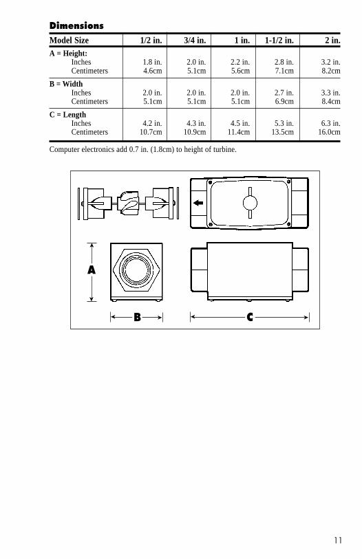
Model Size 1/2 in. 3/4 in. 1 in. 1-1/2 in. 2 in.A = Height:
Inches 1.8 in. 2.0 in. 2.2 in. 2.8 in. 3.2 in.Centimeters 4.6cm 5.1cm 5.6cm 7.1cm 8.2cm
B = WidthInches 2.0 in. 2.0 in. 2.0 in. 2.7 in. 3.3 in.Centimeters 5.1cm 5.1cm 5.1cm 6.9cm 8.4cm
C = LengthInches 4.2 in. 4.3 in. 4.5 in. 5.3 in. 6.3 in.Centimeters 10.7cm 10.9cm 11.4cm 13.5cm 16.0cm
Computer electronics add 0.7 in. (1.8cm) to height of turbine.
Dimensions
A
➤
➤
➤
➤ B ➤
➤ C
9
10
PerformanceLinear Range for 1/2 in.: 10:1 @ ±2.0% of readingLinear Range for 3/4 in. and 1 in.: 10:1 @ ±1.5% of readingLinear Range for 1-1/2 in. and 2 in.: 10:1 @ ±1.0% of readingRepeatability: ±0.1%
Temperature Range -40° to +250°F (-40° to +121°C)These temperatures apply to operations and storage. They are only for the turbine with-out computer electronics. Final operational temperature range is determined by com-puter electronics or accessory modules.
SPECIFICATIONS – Brass
All data on Models 1/2", 3/4", and 1" determined with 1 centipoise solvent test fluid at 70°F(21°C). Data on Models 1-1/2" and 2" is determined with water at 70°F (21°C).
Model Size 1/2 in. 3/4 in. 1 in. 1-1/2 in. 2 in.Linear Flow Range
Frequency Range inLinear Flow Range 45-450 Hz 37-370 Hz 45-475 Hz 35-350 Hz 33-330 Hz
ConnectionsNPT or ISO Threads Yes Yes Yes Yes YesFemale Yes Yes Yes Yes YesInlet/Outlet Size 1/2 in. 3/4 in. 1 in. 1-1/2 in. 2 in.Wrench Size: Inch 1-1/16 in. 1-5/16 in. 1-5/8 in. 2-3/8 in. 3 in. Millimeter 27mm 33mm 41mm 60mm 75mm
* Computer electronics add 0.2 lbs. (0.1kg) to total weight.1 The meter can operate up to this flowrate without damage. Continuous operation will severely
degrade meter life and performance.
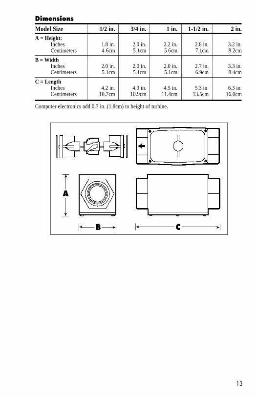
Model Size 1/2 in. 3/4 in. 1 in. 1-1/2 in. 2 in.A = Height:
Inches 1.8 in. 2.0 in. 2.2 in. 2.8 in. 3.2 in.Centimeters 4.6cm 5.1cm 5.6cm 7.1cm 8.2cm
B = WidthInches 2.0 in. 2.0 in. 2.0 in. 2.7 in. 3.3 in.Centimeters 5.1cm 5.1cm 5.1cm 6.9cm 8.4cm
C = LengthInches 4.2 in. 4.3 in. 4.5 in. 5.3 in. 6.3 in.Centimeters 10.7cm 10.9cm 11.4cm 13.5cm 16.0cm
Computer electronics add 0.7 in. (1.8cm) to height of turbine.
Dimensions
A
➤
➤
➤
➤ B ➤
➤ C
11
12
PerformanceLinear Range for 1/2 in.: 10:1 @ ±2.0% of readingLinear Range for 3/4 in. and 1 in.: 10:1 @ ±1.5% of readingLinear Range for 1-1/2 in. and 2 in.: 10:1 @ ±1.0% of readingRepeatability: ±0.1%
Pressure Rating 1,500 PSIG (21 bar) – Standard Stainless Steel Meter3,000 PSIG (207 bar) – High Pressure Stainless Steel Meter
Temperature Range -40° to +250°F (-40° to +121°C)These temperatures apply to operations and storage. They are only for the turbine with-out computer electronics. Final operational temperature range is determined by com-puter electronics or accessory modules.
SPECIFICATIONS – Stainless Steel
All data on Models 1/2", 3/4", and 1" determined with 1 centipoise solvent test fluid at 70°F(21°C). Data on Models 1-1/2" and 2" is determined with water at 70°F (21°C).
Model Size 1/2 in. 3/4 in. 1 in. 1-1/2 in. 2 in.Linear Flow Range
Frequency Range inLinear Flow Range 45-450 Hz 37-370 Hz 45-475 Hz 35-350 Hz 33-330 Hz
ConnectionsNPT or ISO Threads Yes Yes Yes Yes YesFemale Yes Yes Yes Yes YesInlet/Outlet Size 1/2 in. 3/4 in. 1 in. 1-1/2 in. 2 in.Wrench Size: Inch 1-1/16 in. 1-5/16 in. 1-5/8 in. 2-3/8 in. 3 in. Millimeter 27mm 33mm 41mm 60mm 75mm
* Computer electronics add 0.2 lbs. (0.1kg) to total weight.1 The meter can operate up to this flowrate without damage. Continuous operation will severely
degrade meter life and performance.
Model Size 1/2 in. 3/4 in. 1 in. 1-1/2 in. 2 in.A = Height:
Inches 1.8 in. 2.0 in. 2.2 in. 2.8 in. 3.2 in.Centimeters 4.6cm 5.1cm 5.6cm 7.1cm 8.2cm
B = WidthInches 2.0 in. 2.0 in. 2.0 in. 2.7 in. 3.3 in.Centimeters 5.1cm 5.1cm 5.1cm 6.9cm 8.4cm
C = LengthInches 4.2 in. 4.3 in. 4.5 in. 5.3 in. 6.3 in.Centimeters 10.7cm 10.9cm 11.4cm 13.5cm 16.0cm
Computer electronics add 0.7 in. (1.8cm) to height of turbine.
Dimensions
A
➤
➤
➤
➤ B ➤
➤ C
13
14
PerformanceLinear Range for 1 in.: 10:1 @ ±1.5% of readingLinear Range for 1-1/2 in. and 2 in.: 10:1 @ ±1.0% of readingRepeatability: ±0.1%
Temperature Range -40° to +250°F (-40° to +121°C)These temperatures apply to operations and storage. They are only for the turbine with-out computer electronics. Final operational temperature range is determined by com-puter electronics or accessory modules.
SPECIFICATIONS – Flange Fittings
All data on Model 1" determined with 1 centipoise solvent test fluid at 70°F (21°C). Data onModels 1-1/2" and 2" is determined with water at 70°F (21°C).
* Computer electronics add 0.2 lbs. (0.1kg) to total weight.1 The meter can operate up to this flowrate without damage. Contin-
uous operation will severely degrade meter life and performance.
Model Size 1 in. 1-1/2 in. 2 in.A = Length:
Inches 6.75 in. 8.00 in. 9.50 in.Centimeters 17.14cm 20.32cm 24.13cm
B = WidthInches 4.25 in. 5.00 in. 6.00 in.Centimeters 10.80cm 12.71cm 15.24cm
Computer electronics add 0.7 in. (1.8cm) to height of turbine.
Dimensions
B
➤
➤
➤
➤ A
15
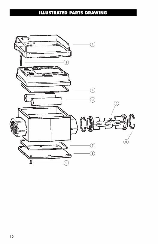
ILLUSTRATED PARTS DRAWING
16
2
3
4
5
67
8
9
1
Item No.No. Part No. Description Req’d.
1 906004-85 EDM Cover Single Access Port (optional) - Fits 1/2",3/4” and 1” Only .............................................................................. 1
906004-86 EDM Cover Dual Access Port (optional) - Fits 1/2",3/4” and 1” Only .............................................................................. 1
6 904005-20 One 05 – 1/2-inch Retaining Ring ................................................... 2
904005-21 One 07 – 3/4-inch Retaining Ring ................................................... 2
904005-22 One 10 – 1-inch Retaining Ring ...................................................... 2
904005-23 One 15 – 1-1/2-inch Retaining Ring ............................................... 2
904005-24 One 20 – 2-inch Retaining Ring ...................................................... 2
125505-01 Flange Gasket Kit with 2 Gaskets (1 in. Neoprene) (not shown) ..... 1
125504-01 Flange Gasket Kit with 2 Gaskets (1 in. Viton) (not shown) ............. 1
125505-02 Flange Gasket Kit with 2 Gaskets (1-1/2 in. Neoprene) (not shown).. 1
125504-02 Flange Gasket Kit with 2 Gaskets (1-1/2 in. Viton) (not shown) ...... 1
125505-03 Flange Gasket Kit with 2 Gaskets (2 in. Neoprene) (not shown) ..... 1
125504-03 Flange Gasket Kit with 2 Gaskets (2 in. Viton)(not shown) .............. 1
7 901003-1 Back Coverplate O-Ring ................................................................. 1
8 125015-2 Back Coverplate .............................................................................. 1
9 904005-13 Back Coverplate Screws .................................................................. 6
17
18
For warranty consideration, parts, or otherservice information, please contact your lo-cal distributor. If you need further assistance,call the GPI Customer Service Department inWichita, Kansas, during normal business hours.
1-888-996-3837
To obtain prompt, efficient service, alwaysbe prepared with the following information:
1. The model number of your turbine.
2. The serial number or manufacturing datecode of your turbine.
3. Specific information about part numbersand descriptions.
For warranty work always be prepared withyour original sales slip or other evidence ofpurchase date.
Returning Parts
Please contact the factory before returningany parts. It may be possible to diagnose thetrouble and identify needed parts in a tele-phone call. GPI can also inform you of anyspecial handling requirements you will needto follow covering the transportation and han-dling of equipment which has been used totransfer hazardous or flammable liquids.
CAUTION: Do not return turbines withoutspecific authority from the GPI Cus-tomer Service Department. Due to strictregulations governing transportation,handling, and disposal of hazardous orflammable liquids, GPI will not acceptturbines for rework unless they are com-pletely free of liquid residue.
CAUTION: Turbines not flushed beforeshipment can be refused and returned tothe sender.
5252 East 36th Street NorthWichita, KS USA 67220-3205TEL: 316-686-7361FAX: 316-686-6746
“A Great P la ins Ventures Subsid iary”
www.gpi.net
1-888-996-3837
Factory Mutual ApprovedIntrinsically Safe for Class I, II, III, Division 1, All Groups.
Limited Warranty Policy
Great Plains Industries, Inc. 5252 E. 36th Street North, Wichita, KS USA 67220-3205, hereby provides alimited warranty against defects in material and workmanship. This product includes a 1-year warranty.The warranty shall extend to the purchaser of this product and to any person to whom such product istransferred during the warranty period.
The warranty period shall begin on the date of the original new equipment purchase. Warrantor’s obligationhereunder shall be limited to repairing defective workmanship or replacing or repairing any defective partor parts. This warranty shall not apply if:
A. the product has been altered or modified outside the warrantor’s duly appointed representative;B. the product has been subjected to neglect, misuse, abuse or damage or has been installed or
operated other than in accordance with the manufacturer’s operating instructions.
To make a claim against this warranty, notice of claim must be given in writing to the company at its aboveaddress no later than 30 days after the expiration of the warranty period. Such notice shall identify thedefect in the product. The company shall, within 14 days of receipt of such notice, notify the customer toeither send the product, transportation prepaid, to the company at its office in Wichita, Kansas, or to dulyauthorized service center. The company shall perform all obligations imposed on it by the terms of thiswarranty within 60 days of receipt of the defective product.
GREAT PLAINS INDUSTRIES, INC. EXCLUDES LIABILITY UNDER THIS WARRANTY FORDIRECT, INDIRECT, INCIDENTAL AND CONSEQUENTIAL DAMAGES INCURRED IN THE USEOR LOSS OF USE OF THE PRODUCT WARRANTED HEREUNDER.
The company herewith expressly disclaims any warranty of merchantability or fitness for any particularpurpose other than for which it was designed.
This warranty gives you specific rights and you may also have other rights which vary from U.S. state toU.S. state.
Note: In compliance with MAGNUSON MOSS CONSUMER WARRANTY ACT – Part 702 (governs theresale availability of the warranty terms).