15
WHITE PAPER Turbo Charging Cabling Infrastructures HPE SMART RATE MULTI-GIGABIT ETHERNET TECHNOLOGY

WHITE PAPER
Turbo Charging Cabling Infrastructures HPE SMART RATE MULTI-GIGABIT ETHERNET TECHNOLOGY

TECHNICAL WHITE PAPER
2
ERROR! NO TEXT OF SPECIFIED STYLE IN DOCUMENT.
CONTENTS HPE Smart Rate multi-gigabit Ethernet technology ............................................ Error! Bookmark not defined. Introduction ....................................................................................................................................................... 3 HPE Smart Rate technology ............................................................................................................................. 4 Operational modes ........................................................................................................................................... 4 Compatibility ..................................................................................................................................................... 4 Rate adaptation ................................................................................................................................................ 5 Power over Ethernet ......................................................................................................................................... 5 MACsec ............................................................................................................................................................ 5 Cabling ............................................................................................................................................................. 5 Gigabit Ethernet (1000BASE-T) ........................................................................................................................ 6 10 Gigabit Ethernet (10GBASE-T) .................................................................................................................... 6 2.5 Gigabit Ethernet (2.5 Gbps Smart Rate) ..................................................................................................... 7 5 Gigabit Ethernet (5 Gbps Smart Rate) ........................................................................................................... 8 Deployment recommendations ......................................................................................................................... 9 Flow control .................................................................................................................................................... 10 Frame size ...................................................................................................................................................... 10 Summary ........................................................................................................................................................ 10 Appendix ......................................................................................................................................................... 11 5 Gigabit Smart Rate cable specification ......................................................................................................... 11 Relationship between ANSI/TIA/EIA, ISO/IEC, and IEEE................................................................................ 11 5 Gbps transmission parameters on cat 5e/class D ........................................................................................ 11 5Gbps transmission parameters on cat 6/class E ........................................................................................... 12 Alien crosstalk ................................................................................................................................................. 12 Alien noise ...................................................................................................................................................... 13 Cabling bundling examples in terms of alien crosstalk .................................................................................... 14

TECHNICAL WHITE PAPER
3
ERROR! NO TEXT OF SPECIFIED STYLE IN DOCUMENT.
INTRODUCTION With the advancement in wireless technologies, enterprise networks are being stressed by the ever increasing number of
wireless devices. 1000BASE-T Ethernet is limited in bandwidth to handle these new demands while 10GBASE-T Ethernet
requires costly upgrades to the majority of cabling installed today—Cat5e and Cat6 cables. This new reality requires the
addition of new cost-effective 2.5GbE and 5GbE link speeds to scale network bandwidth and to deliver increased security to
enterprise IEEE 802.11ac Wave 2 Access Points. There is also a need for other new technologies that would provide IT
professionals with more data rate options to handle the increased network access demands.
The Aruba 5400R and Aruba 3810 series switches include Smart Rate port options. HPE Smart Rate provides higher
bandwidth connectivity and PoE+ power for next generation IEEE 802.11ac devices utilizing existing cabling infrastructure.
Smart Rate ports support auto-negotiated speeds of 1, 2.5, 5, and 10 Gbps with PoE+, and operate over existing Category
5e, 6, and 6A cabling.
TECHNICAL WHITE PAPER
4
ERROR! NO TEXT OF SPECIFIED STYLE IN DOCUMENT.
HPE SMART RATE TECHNOLOGY
Operational modes Smart Rate interfaces support four modes of operation:
• Standards-based IEEE 802.3 1000BASE-T Gigabit Ethernet on Category 5e or better twisted-pair cabling
• 2.5 Gigabit Ethernet on Category 5e or better twisted-pair cabling
• 5 Gigabit Ethernet on Category 5e or better twisted-pair cabling
• Standards-based IEEE 802.3 10GBASE-T 10 Gigabit Ethernet on Category 6 or better twisted-pair cabling
Smart Rate uses IEEE 802.3 twisted-pair auto-negotiation to advertise and determine mutually supported modes of
operation with link partners at startup. This enables Smart Rate to connect to standard-based Ethernet equipment and
establish links at 1000BASE-T and 10GBASE-T speeds. When connected to other Smart Rate interfaces or systems that
support NBASE-T 2.5/5G technology, 2.5 Gbps and 5 Gbps connections can additionally be established.
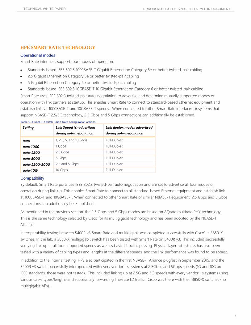
Table 1. ArubaOS-Switch Smart Rate configuration options
Setting Link Speed (s) advertised
during auto-negotiation
Link duplex modes advertised
during auto-negotiation
auto 1, 2.5, 5, and 10 Gbps Full-Duplex
auto-1000 1 Gbps Full-Duplex
auto-2500 2.5 Gbps Full-Duplex
auto-5000 5 Gbps Full-Duplex
auto-2500-5000 2.5 and 5 Gbps Full-Duplex
auto-10G 10 Gbps Full-Duplex
Compatibility By default, Smart Rate ports use IEEE 802.3 twisted-pair auto negotiation and are set to advertise all four modes of
operation during link-up. This enables Smart Rate to connect to all standard-based Ethernet equipment and establish link
at 1000BASE-T and 10GBASE-T. When connected to other Smart Rate or similar NBASE-T equipment, 2.5 Gbps and 5 Gbps
connections can additionally be established.
As mentioned in the previous section, the 2.5 Gbps and 5 Gbps modes are based on AQrate multirate PHY technology.
This is the same technology selected by Cisco for its multigigabit technology and has been adopted by the NBASE-T
Alliance.
Interoperability testing between 5400R v3 Smart Rate and multigigabit was completed successfully with Cisco’s 3850-X
switches. In the lab, a 3850-X multigigabit switch has been tested with Smart Rate on 5400R v3. This included successfully
verifying link-up at all four supported speeds as well as basic L2 traffic passing. Physical layer robustness has also been
tested with a variety of cabling types and lengths at the different speeds, and the link performance was found to be robust.
In addition to the internal testing, HPE also participated in the first NBASE-T Alliance plugfest in September 2015, and the
5400R v3 switch successfully interoperated with every vendor’s systems at 2.5Gbps and 5Gbps speeds (1G and 10G are
IEEE standards, those were not tested). This included linking up at 2.5G and 5G speeds with every vendor’s systems using
various cable types/lengths and successfully forwarding line-rate L2 traffic. Cisco was there with their 3850-X switches (no
multigigabit APs).
TECHNICAL WHITE PAPER
5
ERROR! NO TEXT OF SPECIFIED STYLE IN DOCUMENT.
In addition to NBASE-T based products, there will be products in the market that use a competing 2.5 Gbps and 5 Gbps
multirate technology from Broadcom known as MGBASE-T. MGBASE-T is also the name of the alliance started by
Broadcom built around this technology. The 2.5 Gbps and 5 Gbps modes in MGBASE-T and NBASE-T are not compatible
with each other. When Smart Rate interfaces are connected to equipment using MGBASE-T technology, the link will
autonegotiate and only establish at IEEE 802.3 defined modes of operation (1000BASE-T or 10GBASE-T).
The final adoption by the industry of multigigabit technologies will be from the IEEE’s 802.3bz 2.5/5GBASE-T Task Force
who is overseeing the standardization of the 2.5G and 5G Ethernet.
Rate adaptation Smart Rate supports rate adaptation. This capability enables the Ethernet link to adjust to the highest achievable speed with
a link partner port.
At start-up, a Smart Rate port and its link partner port exchange information about each other’s capabilities – supported
link speed, duplex modes, flow control – using IEEE 802.3 auto-negotiation. Once the information exchange has completed,
both interfaces apply a common set of rules to take maximum advantage of common capabilities by selecting the highest
common speed supported by both ends, and start a process called link training, to determine if cable performance can
support this speed.
If link training is successful, the link is then established at the highest common speed. However, if the link training process
fails, the rate adaptation feature will try up to three additional times to auto-negotiate and re-establish the link at the same
speed. If the connection experiences four consecutive failures, rate adaptation will remove that speed from being advertised.
During the next auto-negotiation attempt, the two ports will then attempt to link at the next speed down.
The process then repeats itself until a link-up is successful, or all commonly advertised speeds are exhausted.
Power over Ethernet Smart Rate switch systems provide up to 30 watts per port of Power over Ethernet for all port speeds using standards-
based IEEE 802.3at PoE+, providing power over twisted-pair structured cabling to PoE powered devices.
Power over Ethernet within Smart Rate provides the same capabilities found in 10/100BASE-TX and 10/100/1000BASE-T
ports in Aruba OS switch systems—allocation of port power, setting of port priorities, configuring of switch-level PoE
redundancy, et cetera.
MACsec Smart Rate provides link-level security through standards-based MAC security, with support for both 256-bit and 128-bit
GCM-AES cipher suites as defined by IEEE 802.1AE and 802.1AEbn.
Cabling One of the key factors of Smart Rate is determining if existing 1000BASE-T cabling will support the higher data rates of
Smart Rate ports. Some initial considerations are:
• 2.5 Gbps transmission is very robust and should work for the vast majority of installed cabling
This is important because the first implementations of Smart Rate are going to operate at 2.5Gbps..
• 5 Gbps transmissions can present challenges for Smart Rate deployments on existing cabling

TECHNICAL WHITE PAPER
6
ERROR! NO TEXT OF SPECIFIED STYLE IN DOCUMENT.
At first this seems counter-intuitive because it isn’t the highest data rate, but, as the "5 Gigabit Ethernet (5 Gbps
Smart Rate)" section will describe, the requirement to operate on installed 1000BASE-T cabling makes 5 Gbps more
challenging than 10GBASE-T. 5 Gbps deployments will require care and likely need testing of existing cable installations
to determine if they are suitable for reliable operation.
Note: This is not a vendor specific challenge but an industry-wide issue.
The following sections provide detail about the cabling support/requirements for each of the four modes.
Gigabit Ethernet (1000BASE-T)
The 1000BASE-T mode within Smart Rate is the most robust of the four modes. Its cabling requirements are identical to the
requirements for all 1000BASE-T interfaces:
• Up to 100 meters on Cat5e, or better, unshielded twisted-pair (UTP) or shielded twisted-pair (STP) cabling.
• Cabling must meet the requirements for Cat5e described in ANSI/TIA/EIA 568-B.2 standard.
• With very few exceptions, Cat5e installations in the field use UTP cabling to save cost, and because 1000BASE-T
doesn’t require the additional noise protection provided by STP cabling.
Note: ANSI/TIA/EIA-568 is the set of standards that deals with cabling requirements in commercial buildings for
telecommunications applications (what is often referred to as structured cabling).
10 Gigabit Ethernet (10GBASE-T)
10GBASE-T has been on the market for several years, and although its cabling requirements are well understood, compared
to 1000BASE-T, 10GBASE-T is significantly more challenging to deploy. 10GBASE-T is inherently a noise-dominated
technology. What this means is that under ideal conditions, 10GBASE-T can operate error-free even beyond 100 meters.
However, the presence of environmental noise (often referred to as alien noise or alien crosstalk) significantly degrades the
link’s signal-to-noise ratio (SNR) and can restrict the maximum cable reach of the link.
In practice, long 10GBASE-T links do not run bit-error free. Because of this, 10GBASE-T has much more demanding cabling
requirements than 1000BASE-T. When 10GBASE-T was originally developed by the IEEE, a new category of cabling
(augmented Cat6 [Cat6A]) and new cable installation procedures with noise mitigation techniques were also developed to
specifically support it. As a result, cable installers pay special attention to how the cables for 10GBASE-T are bundled and
laid out during installation to maintain appropriate cabling performance and minimize the impact of environmental noise
on the link.
Cabling requirements: the cabling requirements for Smart Rate’s 10GBASE-T mode are identical to the requirements for
all 10GBASE-T interfaces:
• Up to 55 meters on Cat6 UTP or STP cabling
• Up to 100 meters on Cat6A or better UTP or STP cabling
From a technical specifications point-of-view, cabling for 10GBASE-T must meet the requirements for Cat6/6A described in
ANSI/TIA/EIA 568-C.2 standard, or the requirements for class E/EA described in ISO/IEC standard 11801. These two
standards deal with structured cabling performance parameters and were updated to include information needed to
support 10 Gbps transmission. The first standard is used predominantly in North America, while the latter is used in Europe
and other parts of the world. For all intents and purposes, they are the same.

TECHNICAL WHITE PAPER
7
ERROR! NO TEXT OF SPECIFIED STYLE IN DOCUMENT.
In addition to the 568-C.2 and 11801 standards, Cat6 installations must also meet alien crosstalk requirements described in
ANSI/TIA/EIA technical service bulletin TSB-155, or ISO/IEC technical report TR-24750. These two documents deal
specifically with noise and gives guidance on cable installation techniques to mitigate alien crosstalk/alien noise when using
Cat6 cabling for 10GBASE-T operation. This requirement is unique to 10GBASE-T—the cabling guidelines for 1000BASE-T
have no such requirements.
2.5 Gigabit Ethernet (2.5 Gbps Smart Rate)
Cabling for the 2.5 Gbps Smart Rate mode is not defined today by a Standards body. HPE R&D testing has shown that the
2.5 Gbps mode performs as well as 1000BASE-T and operates robustly on structured cabling that meets the requirements
for 1000BASE-T operation. Put simply, if the cabling works reliably for 1000BASE-T, it works for 2.5 Gbps. This robustness
can be attributed to three main factors:
• 2.5 Gbps Smart Rate uses a coding and modulation technique that is leveraged from 10GBASE-T. This technique is
more advanced than what is used by 1000BASE-T and has significantly more powerful error correction capability to
deal with errors caused by cable impairments and external noise.
• 2.5 Gbps Smart Rate operates on 100 MHz bandwidth. This is the channel bandwidth that Cat5e cabling is specified,
designed, and tested for. Cat6 also supports 2.5 Gbps operation as it extends that bandwidth to 250 MHz.
• At 100 MHz, the electromagnetic coupling between adjacent cables in a tight bundle of cables is fairly minimal.
Figure 1. Relationship between cable category, frequency and Ethernet data rates - source: http://www.ieee802.org/3/cfi/1114_1/CFI_01_1114.pdf
Cabling in the field that is certified for 1000BASE-T operation has enough channel bandwidth to support 2.5 Gbps Smart
Rate operation. While 2.5 Gbps operates at a higher frequency than 1000BASE-T (62.5 MHz), its coding, modulation, and
error correction technique compensates for additional performance impairments.
Most importantly, its 100 MHz frequency of operation results in minimal impact from external noise. This is key because the
majority of older Cat5e and Cat6 installations give no consideration to mitigating alien crosstalk, minimizing how tightly
multiple cables are bundled together, using shielded twisted-pair cables, and/or taking care to avoid routing cables
TECHNICAL WHITE PAPER
8
ERROR! NO TEXT OF SPECIFIED STYLE IN DOCUMENT.
through noisy environments. In fact, in an effort to keep cable installations easy to work with when routing through
conduits and cable trays, most cable installers have gotten into the habit of “grooming” the cable bundles for 1000BASE-
T applications to keep them neat and tidy. This creates significant amounts of alien crosstalk between the cables due to the
tight bundling. Fortunately, this electromagnetic coupling is frequency dependent, and is fairly minimal at 100 MHz.
Cabling requirements: Cat5e cabling for 2.5 Gbps Smart Rate is identical to the requirements for 100BASE-T. It must meet
the requirements for Cat5e, as described in ANSI/TIA/EIA-568-B.2.
This keeps the cabling guidelines simple and consistent, helps ensure quality cabling continues to be installed/deployed in
the field, and should provide a positive experience when customers drop 2.5 Gbps Smart Rate into their environment.
5 Gigabit Ethernet (5 Gbps Smart Rate)
5 Gbps Smart Rate can be technically challenging, particularly when deployed on Cat5e cabling. There are two main
reasons for this:
5 Gbps mode operates on 200 MHz bandwidth. The previous section showed that Cat5e cabling has a specified
channel of bandwidth of 100 MHz, making it insufficient for 5 Gbps operation. However, higher quality Cat5e cabling
has acceptable performance in the 100–200 MHz range, allowing it to support 5 Gbps operation. Note that Cat5e cable
quality varies greatly between cable vendors, so there are existing Cat5e installations that meet 1000BASE-T operation,
but will have insufficient performance in the 200 MHz range to support reliable 5 Gbps operation. Moving to Cat6
solves this issue since Cat6 is specified and tested to 250 MHz.
• The 200 MHz operating bandwidth used by 5 Gbps falls into a frequency range where electromagnetic coupling
between cables in a tight cable bundle can be significant. This makes the alien noise issue much more problematic.
Because most legacy Cat5e and Cat6 cable plants were installed without regard to alien crosstalk mitigation, the
potential for noise degradation at 5 Gbps on legacy cabling can occur.
5 Gbps deployments in existing cable installations involves a trade-off between the cabling loss and noise. With shorter
cables, the link has greater SNR and can tolerate more noise. With longer cables, the link has less SNR and can tolerate less
noise. For example, testing in the HPE R&D lab has shown that 5 Gbps link with a 100 meters of reach can only tolerate
about 40 meters worth of coupled noise in a 6-around-1 cable bundle configuration. When the same link was shortened to
60 meters, it could tolerate the entire 60 meters worth of coupled noise in the same 6-around-1 configuration.
Cabling requirements: both Cat5e and Cat6 installations, should be tested for acceptable alien crosstalk if the cabling plant
is laid out with significant cable bundling. Guidance for bundled and unbundled 5 Gbps deployments is broken down
below, by category of cabling:
On Cat5e:
• If the cabling is mostly unbundled (minimal alien crosstalk), 5 Gbps Smart Rate can support up to 55 meters without
any testing
• If the cabling is mostly unbundled, 5 Gbps Smart Rate can support up to 100 meters if the channel is tested and passes
the ANSI/TIA/EIA 568-B.2 limit lines for Cat5e when extrapolated out to 200 MHz
• If the cabling is significantly bundled with other cables, the cabling must additionally pass the alien crosstalk
requirements described in ANSI/TIA/EIA TSB-155 or ISO/IEC TR-24750
TECHNICAL WHITE PAPER
9
ERROR! NO TEXT OF SPECIFIED STYLE IN DOCUMENT.
On Cat6:
• If the cabling is mostly unbundled, 5 Gbps Smart Rate can support up to 100 meters of Cat6 without any required
testing, assuming it was previously tested during installation to meet the ANSI/TIA/EIA 568-C.2 Cat6 requirements
• If the cabling is significantly bundled with other cables, 5 Gbps Smart rate can support up to 100 meters of Cat6 if the
cabling passes the alien crosstalk requirements described in ANSI/TIA/EIA TSB-155 or ISO/IEC TR-24750
On Cat6A:
• 5 Gbps can support up to 100 meters provided the cabling was previously tested to Cat6A ANSI/TIA-EIA 568-C.2 or
class EA requirements in ISO/IEC 11801 requirements.
Deployment recommendations 2.5 Gbps Smart Rate is the recommended default. It is as robust as 1000BASE-T and has been demonstrated to run on
many cabling configurations that support 1000BASE-T operation. This mode should meet the wired link bandwidth needs
for the majority of IEEE 802.11ac Wave 2 Access Point designs.
In many cases 10 Gbps Smart Rate may link up successfully on Cat5e configurations or Cat6 configurations of less than 55
meters, but reliable operation is not guaranteed. It is recommended to use the interface speed-duplex configuration setting
to disable 10 Gbps advertisements so that the Smart Rate interface doesn’t attempt to link at 10 Gbps. 10 Gbps Smart Rate
is recommended when the cabling meets the ANSI/TIA/EIA or ISO/IEC requirements for 10GASE-T operation.
If 5Gbps is expected to be deployed on an existing Cat5e cabling plant, testing for both the individual cable/channel
performance and alien crosstalk should be planned and budgeted for. In some cases, the results may show that the cabling
does not meet the requirements for reliable 5 Gbps operation. It is recommended that 5 Gbps be deployed in Cat6 cabling
plants that have sufficient alien crosstalk performance.
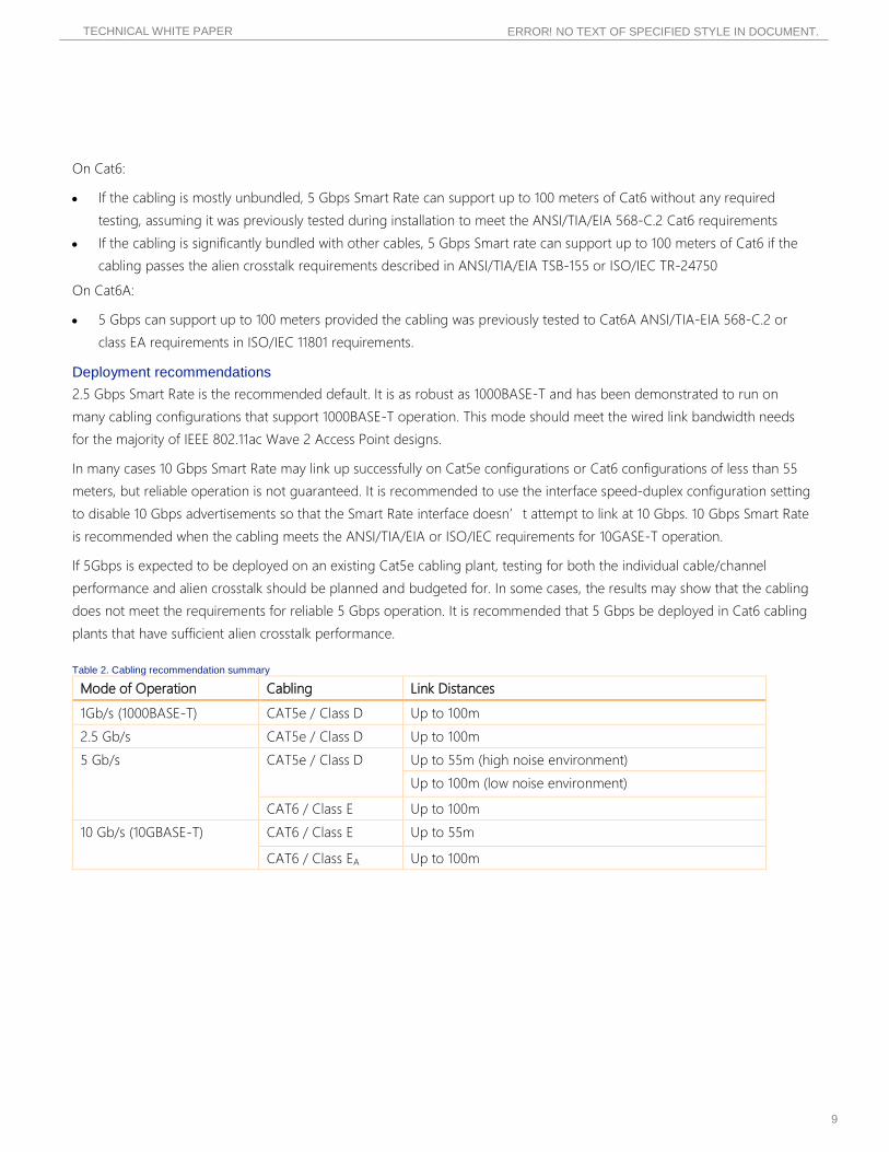
Table 2. Cabling recommendation summary
Mode of Operation Cabling Link Distances
1Gb/s (1000BASE-T) CAT5e / Class D Up to 100m
2.5 Gb/s CAT5e / Class D Up to 100m
5 Gb/s CAT5e / Class D Up to 55m (high noise environment)
Up to 100m (low noise environment)
CAT6 / Class E Up to 100m
10 Gb/s (10GBASE-T) CAT6 / Class E Up to 55m
CAT6 / Class EA Up to 100m

TECHNICAL WHITE PAPER
10
ERROR! NO TEXT OF SPECIFIED STYLE IN DOCUMENT.
Flow control
Smart Rate ports support IEEE 802.3x port-based flow control. This is the same user-port flow control functionality that
supported today on all ArubaOS-switch based switch systems.
Smart Rate ports do not support IEEE 802.1Qbb priority-based flow control. This is not an issue today since 802.1Qbb is
used predominantly in data center applications, and ArubaOS-switch systems do not have software support for priority-
based flow control. If 802.1Qbb becomes a requirement for the Enterprise and Campus in the future, be aware that the
Smart Rate ports cannot support it.
Frame size
Smart Rate ports support 9 KB (9216B) jumbo frames. This is identical to the maximum jumbo frame size supported on
existing ArubaOS-Switch devices. Jumbo frame size is disabled by default.
SUMMARY HPE Smart Rate technology allows for Aruba switches to provide 1, 2.5, 5, and 10 Gbps Ethernet connectivity over existing
copper cabling and PoE+.
Enterprise networks can expect to see the benefits of supporting the next generation of mobile infrastructure and IEEE
802.11ac Wave 2 APs by deploying HPE Smart Rate technology in the network.
TECHNICAL WHITE PAPER
11
ERROR! NO TEXT OF SPECIFIED STYLE IN DOCUMENT.
APPENDIX
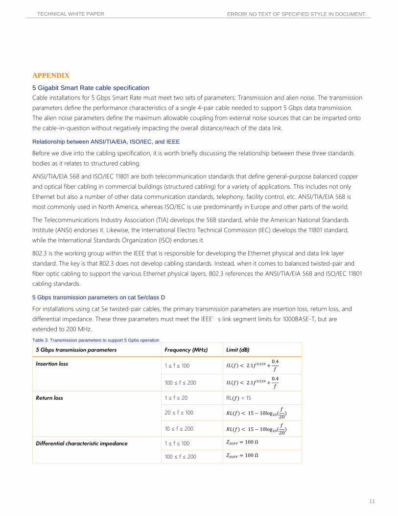
5 Gigabit Smart Rate cable specification Cable installations for 5 Gbps Smart Rate must meet two sets of parameters: Transmission and alien noise. The transmission
parameters define the performance characteristics of a single 4-pair cable needed to support 5 Gbps data transmission.
The alien noise parameters define the maximum allowable coupling from external noise sources that can be imparted onto
the cable-in-question without negatively impacting the overall distance/reach of the data link.
Relationship between ANSI/TIA/EIA, ISO/IEC, and IEEE
Before we dive into the cabling specification, it is worth briefly discussing the relationship between these three standards
bodies as it relates to structured cabling.
ANSI/TIA/EIA 568 and ISO/IEC 11801 are both telecommunication standards that define general-purpose balanced copper
and optical fiber cabling in commercial buildings (structured cabling) for a variety of applications. This includes not only
Ethernet but also a number of other data communication standards, telephony, facility control, etc. ANSI/TIA/EIA 568 is
most commonly used in North America, whereas ISO/IEC is use predominantly in Europe and other parts of the world.
The Telecommunications Industry Association (TIA) develops the 568 standard, while the American National Standards
Institute (ANSI) endorses it. Likewise, the International Electro Technical Commission (IEC) develops the 11801 standard,
while the International Standards Organization (ISO) endorses it.
802.3 is the working group within the IEEE that is responsible for developing the Ethernet physical and data link layer
standard. The key is that 802.3 does not develop cabling standards. Instead, when it comes to balanced twisted-pair and
fiber optic cabling to support the various Ethernet physical layers, 802.3 references the ANSI/TIA/EIA 568 and ISO/IEC 11801
cabling standards.
5 Gbps transmission parameters on cat 5e/class D
For installations using cat 5e twisted-pair cables, the primary transmission parameters are insertion loss, return loss, and
differential impedance. These three parameters must meet the IEEE’s link segment limits for 1000BASE-T, but are
extended to 200 MHz.
Table 3. Transmission parameters to support 5 Gpbs operation
5 Gbps transmission parameters Frequency (MHz) Limit (dB)
Insertion loss 1 ≤ f ≤ 100 𝐼𝐼𝐼𝐼(𝑓𝑓) < 2.1𝑓𝑓0.529 +0.4𝑓𝑓
100 ≤ f ≤ 200 𝐼𝐼𝐼𝐼(𝑓𝑓) < 2.1𝑓𝑓0.529 +0.4𝑓𝑓
Return loss 1 ≤ f ≤ 20 RL(𝑓𝑓) < 15
20 ≤ f ≤ 100 𝑅𝑅𝐼𝐼(𝑓𝑓) < 15 − 10log10(𝑓𝑓
20)
10 ≤ f ≤ 200 𝑅𝑅𝐼𝐼(𝑓𝑓) < 15 − 10log10(𝑓𝑓
20)
Differential characteristic impedance 1 ≤ f ≤ 100 𝑍𝑍𝐷𝐷𝐷𝐷𝐷𝐷𝐷𝐷 = 100 Ω
100 ≤ f ≤ 200 𝑍𝑍𝐷𝐷𝐷𝐷𝐷𝐷𝐷𝐷 = 100 Ω

TECHNICAL WHITE PAPER
12
ERROR! NO TEXT OF SPECIFIED STYLE IN DOCUMENT.
Table 2. Specifies the transmission parameters to support 5 Gbps operation.
The values in Black are the limits for 1000BASE-T in the IEEE 802.3 Ethernet standard. The values in Red are the frequency
extensions out to 200 MHz to support 5 Gbps operation. Notice that the limit line questions for the extended frequency
range are identical to the 1000BASE-T equations.
5Gbps transmission parameters on cat 6/class E
5 Gbps operation is supported on cat 6/class E installations whose transmission performance meet the cat 6 limits specified
in ANSI/TIA/EIA-568-C or the class E limits specified in ISO/IEC 11801.
Alien crosstalk
Alien crosstalk is tested using what is referred as a “6-around-1” cable bundle configuration. The victim cable-under-test
is surrounded by noise sources comprised of six other cables that are tightly bundled to the victim’s cable for a specific
length. Data link traffic is transmitted on all seven links while monitoring the status of the victim link to determine its ability
to function properly—autonegotiate, link-train, transmit/receive traffic error-free or with acceptable bit-error rate, etc). A
cross-section of the 6-around-1 bundle configuration is shown in figure 4.
Figure 2. 6-around-1 alien crosstalk test configuration for cat 5e cabling
Lab testing covered for alien crosstalk used cat 5e cables in nine test configurations:
• Victim link operating at 1 Gbps, with six Aggressor links operating at 1 Gbps. 2.5 Gbps, and 5 Gbps
• Victim link operating at 2.5 Gbps, with six Aggressor links operating at 1 Gbps. 2.5 Gbps, and 5 Gbps
• Victim link operating at 5 Gbps, with six Aggressor links operating at 1 Gbps. 2.5 Gbps, and 5 Gbps
For each test configuration, two tests were conducted to help understand the performance limits and the trade-offs
between alien crosstalk and insertion loss.
Aggressor cables (6)Victim cable
TECHNICAL WHITE PAPER
13
ERROR! NO TEXT OF SPECIFIED STYLE IN DOCUMENT.
The first test sets the coupling distance of the victim and its six aggressors at 60 m. 60 m was chosen to represent a realistic
worst-case coupled length that one would see in field installations. Length is then added to the victim’s link to determine
how much cable reach (insertion loss) can be added while still achieving error-free operation.
The second test sets the victim cable length (insertion loss) at 100 m. The coupling distance of the victim and its six
aggressors start at 100 m and is reduced until the victim link can operate reliably. This tests how much alien crosstalk
coupling can be tolerated with a worst-case 100 m link.
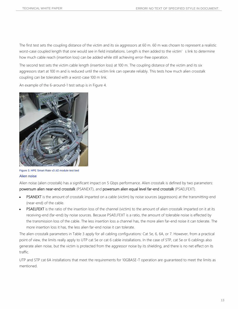
An example of the 6-around-1 test setup is in Figure 4.
Figure 3. HPE Smart Rate v3 zl2 module test bed
Alien noise
Alien noise (alien crosstalk) has a significant impact on 5 Gbps performance. Alien crosstalk is defined by two parameters:
powersum alien near-end crosstalk (PSANEXT), and powersum alien equal level far-end crosstalk (PSAELFEXT).
• PSANEXT is the amount of crosstalk imparted on a cable (victim) by noise sources (aggressors) at the transmitting-end
(near-end) of the cable.
• PSAELFEXT is the ratio of the insertion loss of the channel (victim) to the amount of alien crosstalk imparted on it at its
receiving-end (far-end) by noise sources. Because PSAELFEXT is a ratio, the amount of tolerable noise is effected by
the transmission loss of the cable. The less insertion loss a channel has, the more alien far-end noise it can tolerate. The
more insertion loss it has, the less alien far-end noise it can tolerate.
The alien crosstalk parameters in Table 3 apply for all cabling configurations: Cat 5e, 6, 6A, or 7. However, from a practical
point of view, the limits really apply to UTP cat 5e or cat 6 cable installations. In the case of STP, cat 5e or 6 cablings also
generate alien noise, but the victim is protected from the aggressor noise by its shielding, and there is no net effect on its
traffic.
UTP and STP cat 6A installations that meet the requirements for 10GBASE-T operation are guaranteed to meet the limits as
mentioned.
TECHNICAL WHITE PAPER
14
ERROR! NO TEXT OF SPECIFIED STYLE IN DOCUMENT.
Table 4. Alien crosstalk limits for various lengths of cat 5e cable configurations
Victim link speed Test condition 1 Gbps noise aggressors (6)
2.5 Gbps noise aggressors (6)
5 Gbps noise aggressors (6)
1 Gbps 1000BASE-T Maximum victim length
60 m aggressors
100 m (error-free) 100 m (error-free) 100 m (error-free)
Maximum aggressor length
100 m victim
100 m (error-free) 100 m (error-free) 80 m (error-free)
2.5 Gbps Smart Rate Maximum victim length
60 m aggressors
100 m (error-free) 100 m (error-free) 100 m (error-free)
Maximum aggressor length
100 m victim
100 m (error-free) 100 m (error-free) 80 m (error-free)
5 Gbps Smart Rate Maximum victim length
60 m aggressors
90 m (error-free) 90 m (error-free) 77 m (error-free)
Maximum aggressor length
100 m victim
55 m (error-free) 55 m (error-free) 40 m (error-free)
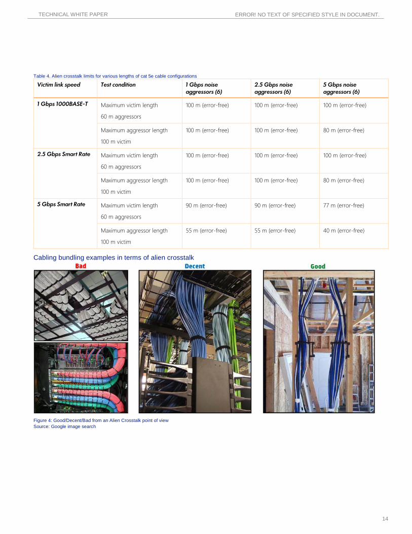
Cabling bundling examples in terms of alien crosstalk
Figure 4: Good/Decent/Bad from an Alien Crosstalk point of view Source: Google image search

1344 CROSSMAN AVE | SUNNYVALE, CA 94089 1.866.55.ARUBA | T: 1.408.227.4500 | FAX: 1.408.227.4550 | [email protected]
www.arubanetworks.com ©2014 Aruba Networks, Inc. Aruba Networks®, Aruba The Mobile Edge Company® (stylized), Aruba Mobilty Management System®, People Move. Networks Must Follow.®, Mobile Edge Architecture®, RFProtect®, Green Island®, ETIPS®, ClientMatch®, Bluescanner™ and The All Wireless Workspace Is Open For Business™ are all Marks of Aruba Networks, Inc. in the United States and certain other countries. The preceding list may not necessarily be complete and the absence of any mark from this list does not mean that it is not an Aruba Networks, Inc. mark. All rights reserved. Aruba Networks, Inc. reserves the right to change, modify, transfer, or otherwise revise this publication and the product specifications without notice. While Aruba Networks, Inc. uses commercially reasonable efforts to ensure the accuracy of the specifications contained in this document, Aruba Networks, Inc. will assume no responsibility for any errors or omissions. XX_Name_XXXX14


