Repair Parts Sheet POWERFUL SOLUTIONS. GLOBAL FORCE. Note: Storing the pump in the vertical position may cause it to lose its prime. If pump loses its prime: 1. Remove cover. 2. Remove relief valve. 3. Fill chamber with oil. 4. Apply Loctite 545 to threads and torque to 10-12 ft-lbs. [14-16 Nm]. 5. Replace pump cover. See Figure 1 for gasket orientation detail and cover screw torquing sequence. L2533 Rev. N 3/2018 For Date Codes Beginning with the Letters “C”, “D” and “E” To Protect Your Warranty, Use Only ENERPAC Hydraulic Oil. Enerpac recommends that all kit components be installed to insure optimum performance of the repaired product. Turbo II Air Pumps II TURBO ® Contents: Figure 1 — Treadle Assembly, T Version ..................................2 Figure 2 — Treadle Assembly, M, C, S Version ........................3 Figure 2a & 2b – Handle Assembly, R Version .........................4 Figure 3 — Cover Assembly .....................................................5 Figure 4 — Hydraulic Section Detail.........................................6 Figure 5 — Seal Push Tool .......................................................7 Figure 6 — Seal Push Tool .......................................................7 Figure 7 — Air Motor Assembly ...............................................8 Figure 8 — Release Valve.........................................................9 Figure 9 — Manual Valve........................................................10 Figure 10 — Pump Manifolds, PAS Version ...........................11 Figure 11 — Pump Manifold, PAC Version .............................11 Table 1 — Relief Valve Setting................................................12 Table 2 — Repair Kit Application............................................12 * Turbo II original release starts at Date Code “C”.
Transcript
Repair Parts Sheet
POWERFUL SOLUTIONS. GLOBAL FORCE.
Note: Storing the pump in the vertical position may cause it to lose its prime. If pump loses its prime:
1. Remove cover.
2. Remove relief valve.
3. Fill chamber with oil.
4. Apply Loctite 545 to threads and torque to 10-12 ft-lbs. [14-16 Nm].
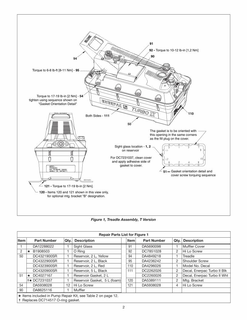
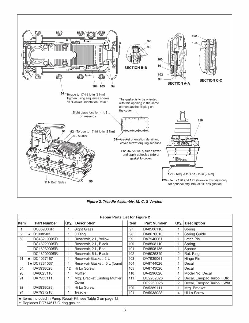
5. Replace pump cover. See Figure 1 for gasket orientation detail and cover screw torquing sequence.
L2533 Rev. N 3/2018 For Date Codes Beginning with the Letters “C”, “D” and “E”
To Protect Your Warranty, Use Only ENERPAC Hydraulic Oil.Enerpac recommends that all kit components be installed to insure optimum performance of the repaired product.
Turbo II Air Pumps
IITURBO®
Contents:
Figure 1 — Treadle Assembly, T Version ..................................2
Figure 2 — Treadle Assembly, M, C, S Version ........................3
Figure 2a & 2b – Handle Assembly, R Version .........................4
Item Part Number Qty. Description Item Part Number Qty. Description
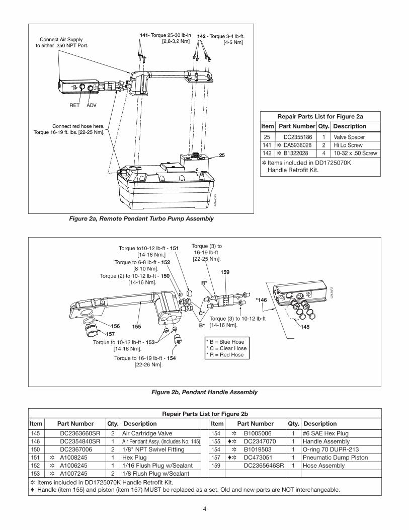
✲ Items included in DD1725070K Handle Retrofit Kit. ♦ Handle (item 155) and piston (item 157) MUST be replaced as a set. Old and new parts are NOT interchangeable.
Figure 2b, Pendant Handle Assembly
Figure 2a, Remote Pendant Turbo Pump Assembly
Connect red hose here.Torque 16-19 ft. lbs. [22-25 Nm].
141- Torque 25-30 lb-in[2,8-3,2 Nm] Connect Air Supply
to either .250 NPT Port.
142 - Torque 3-4 lb-ft.[4-5 Nm]
25
ADVRET
RE
F46
01F
1
25 DC2355186 1 Valve Spacer 141 ✲ DA5938028 2 Hi Lo Screw 142 ✲ B1322028 4 10-32 x .50 Screw
✲Items included in DD1725070K Handle Retrofit Kit.
Repair Parts List for Figure 2a
Item Part Number Qty. Description
5
H Items included in Pump Repair Kit, see Table 2 on page 12. = Replaces and interchangeable with gasket DC7872037.
60 DC3913900SR 1 Blk Cover Assy. (incl 61-87) DC3914900SR 1 Red Cover Assy. (incl 61-87) 61 DA5295034 1 Swivel Coupler 62 H A8001018SR 1 Filter 63 DA4847799 1 Stamped Bracket 64 DA5026349 1 Ret. Ring 65 H B1220503 1 O Ring Ref B839503 66 DA5938028 6 Hi Lo Screw 67 U972038026-3 1 Air Tool Oil Decal 68 DA7931026 1 Caution Decal 69 H DC4997900K 1 Gasket Set 70 H DA4390118 1 Filter 71 H B1005503 1 O Ring 72 H DC7838028 1 1/4 x 3/8" Hi Lo Screw
73 DA4802051SR 1 Air Button 77 DA4871118 1 Breather 78 A1009245 1 3/8 Flush Plug W/Sealant 79 H DA5349503 1 O Ring (Wear Coated) 80 H B1010503 1 O Ring 81 DC708440 1 Poppet 82 U972038026-2 1 Breather Vent Decal 83 B1224503 1 O Ring Ref J711041 84 DC821110 1 Compression Spring 85 DC4077160 1 3/16" Retainer 86 =H DA6956037 1 Gasket 88 H DA5521149 1 Retaining Pin 89 H DC5217049 1 Retaining Ring
67
60
66 - Apply 17-19 lb-in [2 Nm] of torque
69
68
Fill cap / vent plug
86 - Apply adhesive side of gasket to cover
Lubricate with Lubriplate DS-ES grease - 80Lubricate with Lubriplate DS-ES grease - 79
Apply Loctite PST 59241 - 78or Vibraseal to threads.
Apply 15-20 lb-ft [20-27 Nm] of torque.
77
SECTION B-B
84
85 -Locking tabs on retaining ring must be pointed away from spring
8381
88 - Bend clip to retain motor assembly.
73
66 - Apply 17-19 lb-in [2 Nm] of torque
Apply Lubriplate 630-AA
65
64 63
61
62 89
Install screw until O-Ringis slightly compressed.Apply about 8-10 lb-in.
[1 Nm] of torque.
72
7071
SECTION C-C
82
Figure 3, Cover Assembly
Repair Parts List for Figure 3
Item Part Number Qty. Description Item Part Number Qty. Description
6
21
22
23 – See note #1
18 – See note #4
17 – Bearing to be installed with chamfer to the outside16 – Install step seal with step towards mounting bracket.
SECTION A-A
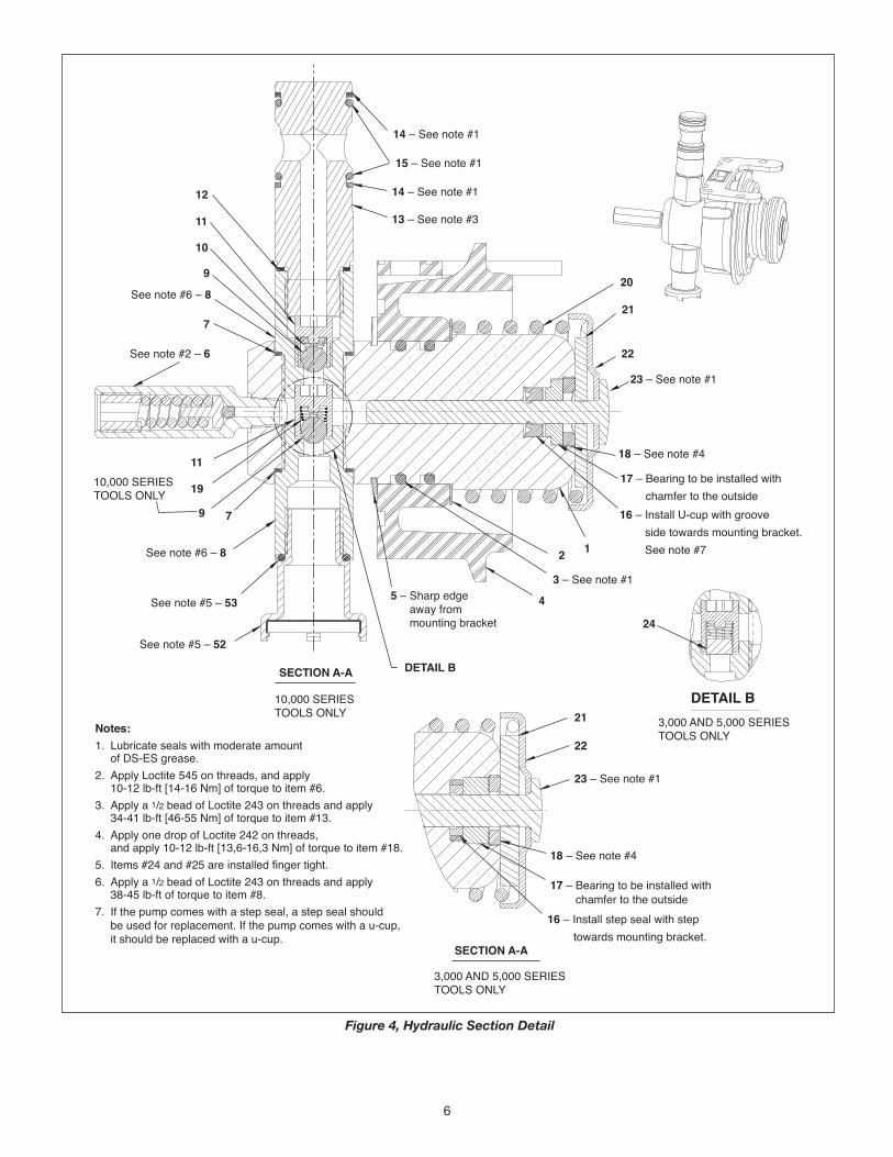
Notes:1. Lubricate seals with moderate amount of DS-ES grease.2. Apply Loctite 545 on threads, and apply 10-12 lb-ft [14-16 Nm] of torque to item #6.3. Apply a 1/2 bead of Loctite 243 on threads and apply 34-41 lb-ft [46-55 Nm] of torque to item #13.4. Apply one drop of Loctite 242 on threads, and apply 10-12 lb-ft [13,6-16,3 Nm] of torque to item #18.5. Items #24 and #25 are installed finger tight.6. Apply a 1/2 bead of Loctite 243 on threads and apply 38-45 lb-ft of torque to item #8.7. If the pump comes with a step seal, a step seal should be used for replacement. If the pump comes with a u-cup, it should be replaced with a u-cup.
3,000 AND 5,000 SERIESTOOLS ONLY
20
21
22
23 – See note #1
14 – See note #1
14 – See note #1
13 – See note #3
15 – See note #1
18 – See note #4
17 – Bearing to be installed with chamfer to the outside16 – Install U-cup with groove side towards mounting bracket. See note #7
12
3 – See note #15 – Sharp edge away from mounting bracket
4
SECTION A-A
10,000 SERIESTOOLS ONLY
DETAIL B
See note #5 – 52
See note #5 – 53
See note #6 – 8
See note #6 – 8
9 7
19
11
See note #2 – 6
9
10
7
11
12
10,000 SERIESTOOLS ONLY
24
DETAIL B3,000 AND 5,000 SERIESTOOLS ONLY
Figure 4, Hydraulic Section Detail
7
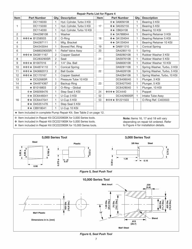
0.63
ø
0.37
0.27
5 ø
0.76
5 ø
0.82
ø
0.65
ø
0.90
SteelPlastic 3/8 Hex
1.30
0.74
ø
0.10
0.30
ø
Steel
[25,
4 D
ia.]
.75
Dia
.
15˚
.815Blend
Med. knurl[5,8]
.460
Dia
.
.625
Dia
.
Mat'l Steel
.230
[11,
7 D
ia.]
[15,
9 D
ia.]
[20,7]
[19,
1 D
ia.]
1.00
Dia
.
Dimensions in in. [mm]
.425
Dia
.
Mat'l Plastic
[10,
8 D
ia.]
Dimensions in in. [mm]
Figure 5, Seal Push Tool
Figure 6, Seal Push Tool
5,000 Series Tool 3,000 Series Tool
10,000 Series Tool
Repair Parts List for Figure 4Item Part Number Qty. Description Item Part Number Qty. Description
11 ❖ ✜ ❉ H DA3682013 2 Ball Guide DA4628108 1 Spring Washer, Turbo, 5 KSI12 ❖ ✜ ❉ H DC170167 1 Copper Gasket DA4284108 1 Spring Washer, Turbo, 10 KSI13 H DC5268SR 1 Pressure Tube 10 KSI
23 DC6406040 1 Plunger, 3 KSI
14 H DA4974367 2 Backup Ring DC6427040 1 Plunger, 5 KSI15 H B1016803 2 O-Ring – Global DC6428040 1 Plunger, 10 KSI
16
❉ H DA9269476 1 Step Seal 3 KSI 24 ✜ ❉ ❖ H DC4440 1 Poppet ❉ H DC6446041 1 U-Cup 3 KSI 52 DC442900SR 1 Intake Tube Assy ✜ H DC6447041 1 U-Cup 5 KSI 53 ✜ ❉ ❖ H B1221503 1 O-Ring Ref. C403503 ✜ H DA5351476 1 Step Seal 5 KSI ❖ H CB918041 1 U-Cup 10 KSI
H Item included in complete Pump Repair Kit. See Table 2 on page 12.
❉ Item included in Repair Kit DC2220900K for 3,000 Series tools.✜ Item included in Repair Kit DC2221900K for 5,000 Series tools.❖ Item included in Repair Kit DC2222900K for 10,000 Series tools.
Note: Items 16, 17 and 18 will vary depending on repair kit ordered. Refer to Figure 4 for installation details.
8
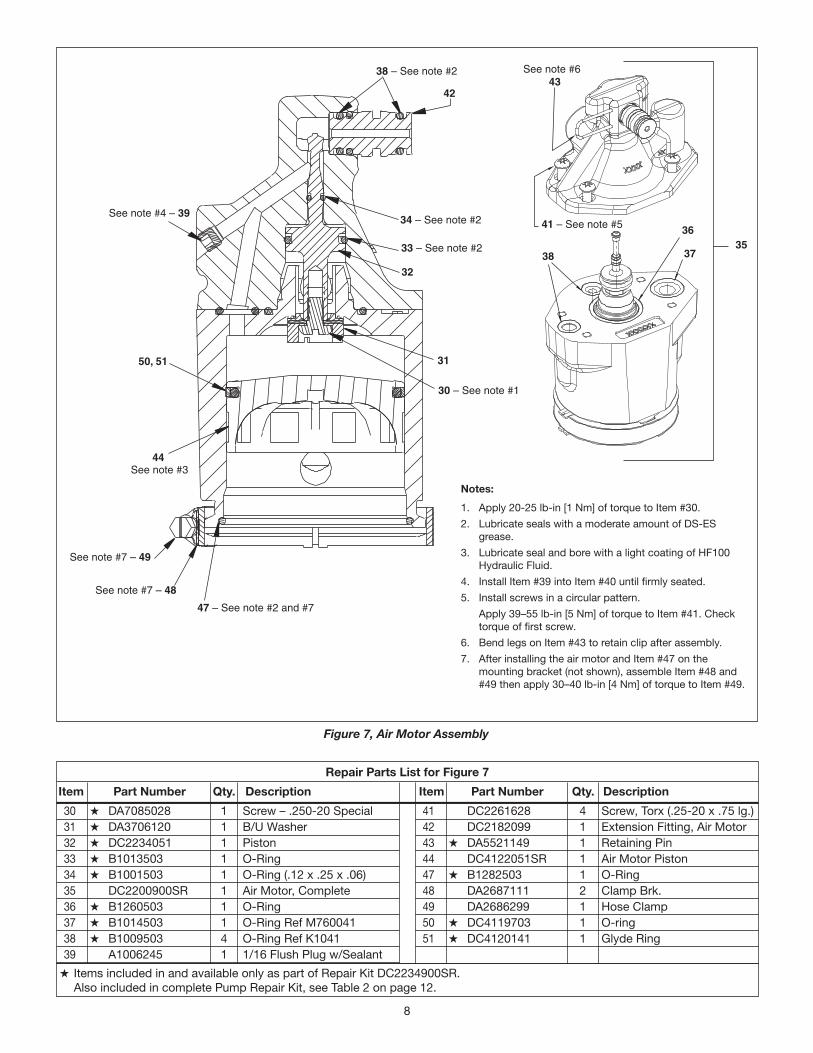
Repair Parts List for Figure 7
Item Part Number Qty. Description Item Part Number Qty. Description
H Items included in and available only as part of Repair Kit DC2234900SR. Also included in complete Pump Repair Kit, see Table 2 on page 12.
30 H DA7085028 1 Screw – .250-20 Special 31 H DA3706120 1 B/U Washer 32 H DC2234051 1 Piston 33 H B1013503 1 O-Ring 34 H B1001503 1 O-Ring (.12 x .25 x .06) 35 DC2200900SR 1 Air Motor, Complete 36 H B1260503 1 O-Ring 37 H B1014503 1 O-Ring Ref M760041 38 H B1009503 4 O-Ring Ref K1041 39 A1006245 1 1/16 Flush Plug w/Sealant
41 DC2261628 4 Screw, Torx (.25-20 x .75 lg.) 42 DC2182099 1 Extension Fitting, Air Motor 43 H DA5521149 1 Retaining Pin 44 DC4122051SR 1 Air Motor Piston 47 H B1282503 1 O-Ring 48 DA2687111 2 Clamp Brk. 49 DA2686299 1 Hose Clamp 50 H DC4119703 1 O-ring 51 H DC4120141 1 Glyde Ring
38
36
37
41 – See note #5
See note #6 43
See note #4 – 39
See note #7 – 49
47 – See note #2 and #7
31
35
44
50, 51
32
See note #7 – 48
30 – See note #1
34 – See note #2
See note #3
33 – See note #2
42
38 – See note #2
Figure 7, Air Motor Assembly
Notes:
1. Apply 20-25 lb-in [1 Nm] of torque to Item #30.2. Lubricate seals with a moderate amount of DS-ES
grease.3. Lubricate seal and bore with a light coating of HF100
Hydraulic Fluid.4. Install Item #39 into Item #40 until firmly seated. 5. Install screws in a circular pattern. Apply 39–55 lb-in [5 Nm] of torque to Item #41. Check
torque of first screw.6. Bend legs on Item #43 to retain clip after assembly.7. After installing the air motor and Item #47 on the
mounting bracket (not shown), assemble Item #48 and #49 then apply 30–40 lb-in [4 Nm] of torque to Item #49.
9
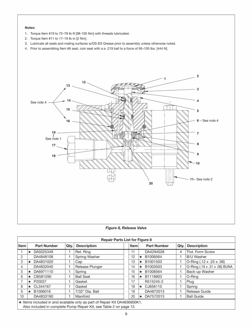
Repair Parts List for Figure 8
Item Part Number Qty. Description Item Part Number Qty. Description
H Items included in and available only as part of Repair Kit DA4836900K1. Also included in complete Pump Repair Kit, see Table 2 on page 12.
1 H DA5025349 1 Ret. Ring 2 DA4848108 1 Spring Washer 3 H DA4831020 1 Cap 4 DA4832040 1 Release Plunger 5 H DA6971110 1 Spring 6 H CB581290 1 Ball Seat 7 H P20037 1 Gasket 8 H CL344167 1 Gasket 9 H B1006016 1 7/32" Dia. Ball 10 DA4833190 1 Manifold
11 DA4294028 4 Thd. Form Screw 12 H B1006564 1 B/U Washer 13 H B1001503 1 O-Ring (.12 x .25 x .06) 14 H B1003503 1 O-Ring (.19 x .31 x .06) BUNA 15 H B1008564 1 Back-up Washer 16 H B1118903 1 O-Ring 17 R515245-2 1 Plug 18 H CJ656110 1 Spring 19 DA4872013 1 Release Guide 20 H DA7572013 1 Ball Guide
12
3
4
5
6 – See note 4
7
8
9
10
11– See note 220
18
17
19
13
14
15
16
See note 1
See note 4
12
Figure 8, Release Valve
Notes:
1. Torque Item #19 to 72–78 lb-ft [98-105 Nm] with threads lubricated.2. Torque Item #11 to 17–19 lb-in [2 Nm].3. Lubricate all seals and mating surfaces w/DS-ES Grease prior to assembly unless otherwise noted.4. Prior to assembling Item #6 seat, coin seat with a ø .219 ball to a force of 95–105 lbs. [444 N].
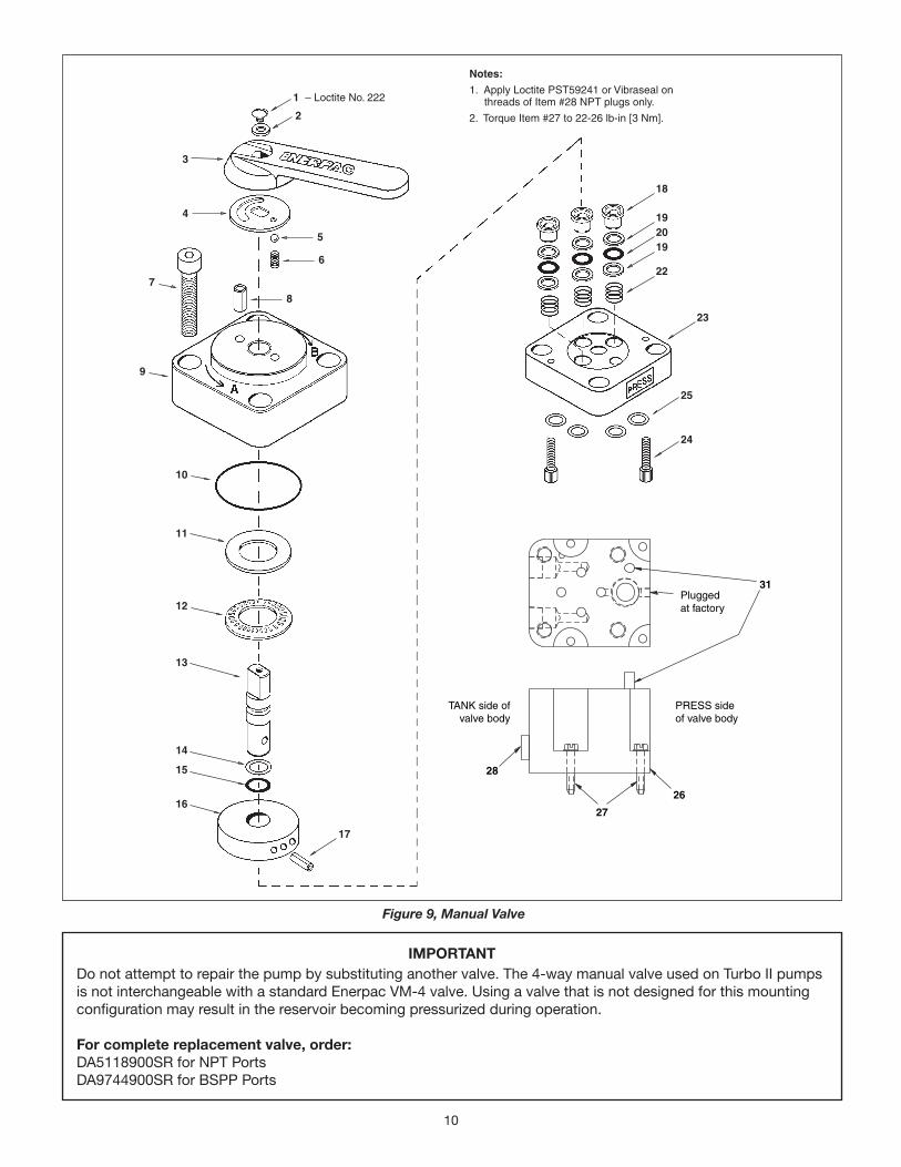
10
11
4
3
12
10
9
7
13
14
15
16
17
1 – Loctite No. 222
2
8
6
5
18
192019
22
23
25
24
26
27
28
Pluggedat factory
PRESS side of valve body
TANK side ofvalve body
31
Notes:
1. Apply Loctite PST59241 or Vibraseal on threads of Item #28 NPT plugs only.
2. Torque Item #27 to 22-26 lb-in [3 Nm].
Figure 9, Manual Valve
IMPORTANTDo not attempt to repair the pump by substituting another valve. The 4-way manual valve used on Turbo II pumps is not interchangeable with a standard Enerpac VM-4 valve. Using a valve that is not designed for this mounting configuration may result in the reservoir becoming pressurized during operation.
For complete replacement valve, order:DA5118900SR for NPT PortsDA9744900SR for BSPP Ports
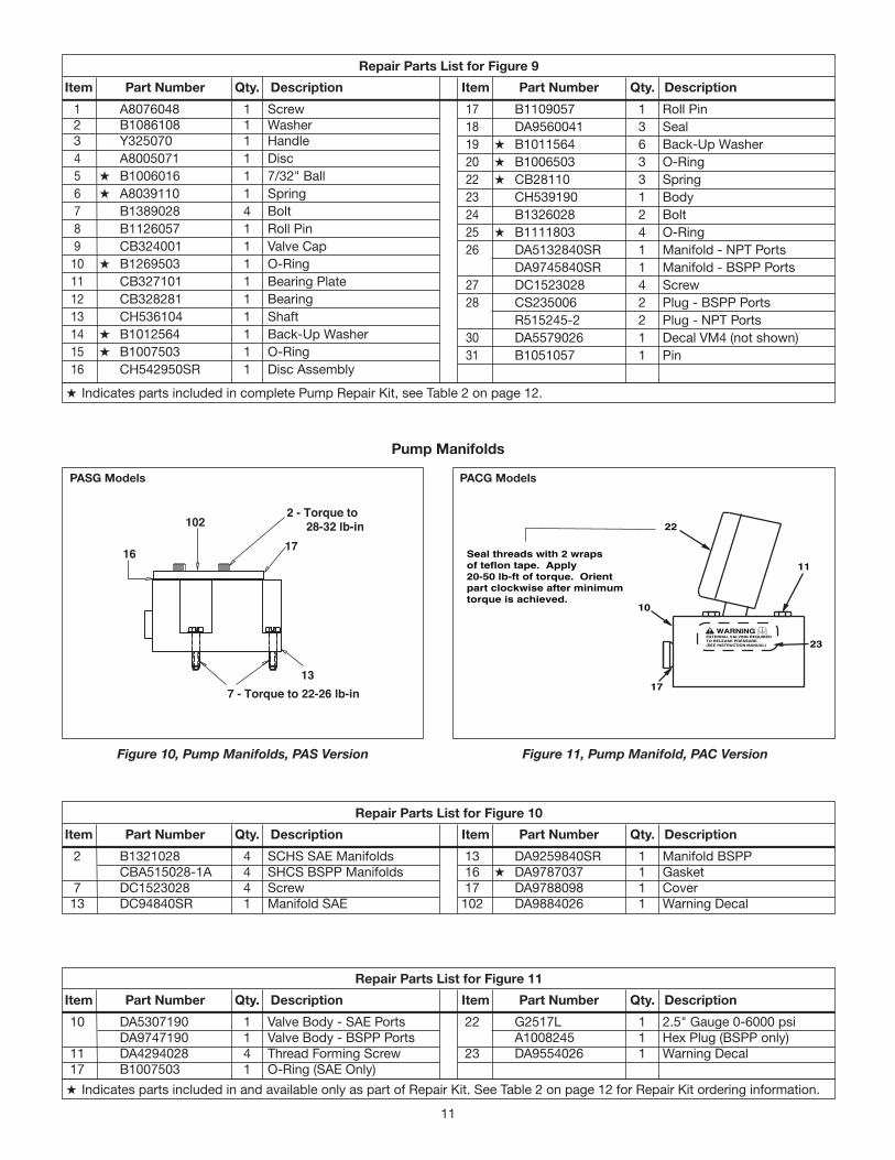
11
H Indicates parts included in complete Pump Repair Kit, see Table 2 on page 12.
1 A8076048 1 Screw 2 B1086108 1 Washer 3 Y325070 1 Handle 4 A8005071 1 Disc 5 H B1006016 1 7/32" Ball 6 H A8039110 1 Spring 7 B1389028 4 Bolt 8 B1126057 1 Roll Pin 9 CB324001 1 Valve Cap 10 H B1269503 1 O-Ring 11 CB327101 1 Bearing Plate 12 CB328281 1 Bearing 13 CH536104 1 Shaft 14 H B1012564 1 Back-Up Washer 15 H B1007503 1 O-Ring 16 CH542950SR 1 Disc Assembly
17 B1109057 1 Roll Pin 18 DA9560041 3 Seal 19 H B1011564 6 Back-Up Washer 20 H B1006503 3 O-Ring 22 H CB28110 3 Spring 23 CH539190 1 Body 24 B1326028 2 Bolt 25 H B1111803 4 O-Ring 26 DA5132840SR 1 Manifold - NPT Ports DA9745840SR 1 Manifold - BSPP Ports 27 DC1523028 4 Screw 28 CS235006 2 Plug - BSPP Ports R515245-2 2 Plug - NPT Ports 30 DA5579026 1 Decal VM4 (not shown) 31 B1051057 1 Pin
Repair Parts List for Figure 9
Item Part Number Qty. Description Item Part Number Qty. Description
H Indicates parts included in and available only as part of Repair Kit. See Table 2 on page 12 for Repair Kit ordering information.
Seal threads with 2 wraps of teflon tape. Apply 20-50 lb-ft of torque. Orient part clockwise after minimum torque is achieved.
Figure 10, Pump Manifolds, PAS Version Figure 11, Pump Manifold, PAC Version
PASG Models PACG Models
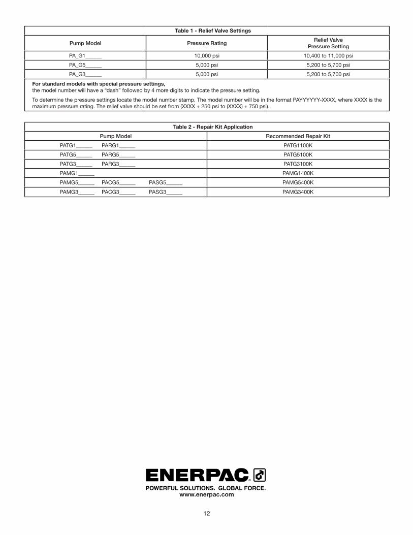
Table 1 - Relief Valve Settings
Pump Model Pressure Rating Relief Valve Pressure Setting
PA_G1______ 10,000 psi 10,400 to 11,000 psi
PA_G5______ 5,000 psi 5,200 to 5,700 psi
PA_G3______ 5,000 psi 5,200 to 5,700 psi
For standard models with special pressure settings,the model number will have a “dash” followed by 4 more digits to indicate the pressure setting.
To determine the pressure settings locate the model number stamp. The model number will be in the format PAYYYYYY-XXXX, where XXXX is the maximum pressure rating. The relief valve should be set from (XXXX + 250 psi to (XXXX) + 750 psi).


![QTY ITEM# TOTAL ITEM DESCRIPTION SIZE PRICE QTY ITEM ...€¦ · 822690 Alberto VO5 15 oz. Shampoo - Extra Body [C] $2.65 822976 Suave 15 oz. Daily Clarifying Shampoo [C] $2.65 ...](https://static.documents.pub/doc/80x56/5f4e4912df7eba404838258f/qty-item-total-item-description-size-price-qty-item-822690-alberto-vo5-15-oz.jpg)


![QTY ITEM# TOTAL ITEM DESCRIPTION SIZE PRICE QTY ITEM ... · 10146 Blue Diamond 4 oz. Almonds Habanero BBQ [K G] $3.65 10252 Snyder's 2.25 oz. Bacon Cheddar Pretzel Pieces [K] $1.00](https://static.documents.pub/doc/80x56/5ff90eba236634375369248c/qty-item-total-item-description-size-price-qty-item-10146-blue-diamond-4-oz.jpg)

