AUT Journal of Modeling and Simulation AUT J. Model. Simul., 49(1)(2017)23-32 DOI: 10.22060/miscj.2016.842 Turbo Expander System Behavior Improvement Using an Adaptive Fuzzy PID Controller M. Taleshian Jelodar 1* , H. Rastegar 2 , M. Pichan 2 1 Department of Engineering, Islamshahr Branch, Islamic Azad University, Islamshahr, Iran 2 Electrical Engineering Department, Amirkabir University of Technology, Tehran, Iran ABSTRACT: Turboexpanders are used in industries for cooling, liquefaction and also power generation. An important part of these turbines is the variable angle nozzlecausing a nonlinear behavior that is not well recognized among the prime movers of the dispersed generators. In this paper, at first, the turbo expander system is evaluated in detail and its nonlinear behavior is investigated. Then, the system is linearized and the variations of its eigenvalues are investigated by a system modal analysis for some changes in input gas stream parameters. Afterwards, the variations of nozzle angle and output pressure are studied using a conventional PID controller. Due to the system nonlinearity, adaptive PID and fuzzy controllers are then designed to improve the system behavior by controlling mechanical parts of turbine nozzle actuator. An adaptive controller uses a fuzzy system as a nonlinear tuner to specify the coefficients for conventional PID controller of the system. A comparison of controllers’ effects is presented. Simulation results show that the turbine response to step changes in gas flow rate or pressure would be steadier when the adaptive or fuzzy controllers are used. Review History: Received: 03 November 2015 Revised: 3 April 2016 Accepted: 21 May 2016 Available Online: 25 May 2016 Keywords: Turbo Expander Modal Analysis Adaptive PID Fuzzy control Nozzle Angle 23 1- Introduction Turbo-expander is a good replacement for the conventional pressure regulating valves in gas transmission pipes which can produce mechanical work besides reducing the pressure of the input gas. Replacing the regulator valves with these turbines, not only decreases the gas pressure passing through the turbine but also recovers a large amount of high-pressure gas energy in the form of mechanical energy. This process is almost an isentropic process in the expander turbine [1, 2]. Using turbo-expanders has a long history in some industries for cooling processes, liquefaction processes, compressor driving, etc., and a relatively newer application is driving the electrical generators according to Fig. 1. Depending on gas flow rate and pressure ratio, these systems can produce up to several megawatts power in gas pressure reduction stations [3, 4, 5]. 2- The Problem Statement Some of the former studies about turbo-expanders are on the basis of applying operational models of these systems in very small scales [6]. In these types of studies, the expander turbine is not usually modeled and only the turbine is studied in the working condition by building an operational setup in small scale. Using the turbo-expanders for producing electrical energy via a permanent magnet generator was investigated in [7]. In this paper, variations of the turbine parameters like efficiency, torque and produced power were also studied. An expander turbine was used beside the pressure regulator valve and an empirical analysis of the system was done in [8, 9]. An analysis of turbo-expanders on the basis of thermodynamic fundamentals and continuity and momentum equation was presented in [10]. This study is a semi-empirical type and is about energy recovery in the form of mechanical energy from small heat sources in the cycle called Organic Rankine Cycle. A model of turbo-expander replacing the pressure regulator valve is presented in [11]. In this study, some arrangements of using this equipment coupled with the electrical generators are investigated. Afterward, a simple model of the expander turbine is presented regarding ideal gas and constant pressure ratio assumption across the turbine. Applying expander turbines for producing electrical energy is investigated with more details in [12,13,14] and power quality problems in various operational conditions are studied by using synchronous generators. The model of turbo-expander is the same as the one used in [11] but, a section is added to the system that is related to shaft and gearbox. By adding shaft and gearbox models, the effects on transient stability of the system are investigated. This paper focuses on the nonlinear behavior of turbo expanders regarding nozzle control system limitations when the gas flow or pressure changes. Then some analyses Corresponding author, E-mail: [email protected]Electrical Network Gear Box IG Electrical Transformer Expander Turbine Induction Generator Q 1 Pr 1 T 1 Pr 2 T 2 Q 2 High Pressure Gas Low Pressure Gas Fig. 1. A simple diagram of Turbo-Expander system coupled with electrical generator
Transcript
AUT Journal of Modeling and Simulation
AUT J. Model. Simul., 49(1)(2017)23-32DOI: 10.22060/miscj.2016.842
Turbo Expander System Behavior Improvement Using an Adaptive Fuzzy PID Controller
M. Taleshian Jelodar1*, H. Rastegar2, M. Pichan2
1 Department of Engineering, Islamshahr Branch, Islamic Azad University, Islamshahr, Iran2 Electrical Engineering Department, Amirkabir University of Technology, Tehran, Iran
ABSTRACT: Turboexpanders are used in industries for cooling, liquefaction and also power generation. An important part of these turbines is the variable angle nozzlecausing a nonlinear behavior that is not well recognized among the prime movers of the dispersed generators. In this paper, at first, the turbo expander system is evaluated in detail and its nonlinear behavior is investigated. Then, the system is linearized and the variations of its eigenvalues are investigated by a system modal analysis for some changes in input gas stream parameters. Afterwards, the variations of nozzle angle and output pressure are studied using a conventional PID controller. Due to the system nonlinearity, adaptive PID and fuzzy controllers are then designed to improve the system behavior by controlling mechanical parts of turbine nozzle actuator. An adaptive controller uses a fuzzy system as a nonlinear tuner to specify the coefficients for conventional PID controller of the system. A comparison of controllers’ effects is presented. Simulation results show that the turbine response to step changes in gas flow rate or pressure would be steadier when the adaptive or fuzzy controllers are used.
Review History:
Received: 03 November 2015Revised: 3 April 2016Accepted: 21 May 2016Available Online: 25 May 2016
1- IntroductionTurbo-expander is a good replacement for the conventional pressure regulating valves in gas transmission pipes which can produce mechanical work besides reducing the pressure of the input gas. Replacing the regulator valves with these turbines, not only decreases the gas pressure passing through the turbine but also recovers a large amount of high-pressure gas energy in the form of mechanical energy. This process is almost an isentropic process in the expander turbine [1, 2].Using turbo-expanders has a long history in some industries for cooling processes, liquefaction processes, compressor driving, etc., and a relatively newer application is driving the electrical generators according to Fig. 1. Depending on gas flow rate and pressure ratio, these systems can produce up to several megawatts power in gas pressure reduction stations [3, 4, 5].
2- The Problem StatementSome of the former studies about turbo-expanders are on the basis of applying operational models of these systems in very small scales [6]. In these types of studies, the expander turbine is not usually modeled and only the turbine is studied in the working condition by building an operational setup in small scale. Using the turbo-expanders for producing electrical energy via a permanent magnet generator was investigated in [7]. In this paper, variations of the turbine parameters like efficiency, torque and produced power were also studied. An expander turbine was used beside the pressure regulator valve and an empirical analysis of the system was done in [8, 9]. An analysis of turbo-expanders on the basis of thermodynamic fundamentals and continuity and momentum equation was presented in [10]. This study is a semi-empirical type and is about energy recovery in the form of mechanical energy from small heat sources in the cycle called Organic Rankine Cycle. A model of turbo-expander replacing the pressure regulator valve is presented in [11]. In this study, some arrangements of using this equipment coupled with the electrical generators are investigated. Afterward, a simple model of the expander turbine is presented regarding ideal gas and constant pressure ratio assumption across the turbine. Applying expander turbines for producing electrical energy is investigated with more details in [12,13,14] and power quality problems in various operational conditions are studied by using synchronous generators. The model of turbo-expander is the same as the one used in [11] but, a section is added to the system that is related to shaft and gearbox. By adding shaft and gearbox models, the effects on transient stability of the system are investigated.This paper focuses on the nonlinear behavior of turbo expanders regarding nozzle control system limitations when the gas flow or pressure changes. Then some analyses
Fig. 1. A simple diagram of Turbo-Expander system coupled with electrical generator
M. Taleshian Jelodar et al., AUT J. Model. Simul., 49(1)(2017)23-32, DOI: 10.22060/miscj.2016.842
24
are done on the whole linearized model of the system. It is shown that turbo-expander has a nonlinear behavior and a conventional PID controller cannot be a proper choice for nozzle system. So, an adaptive fuzzy PID controller and a pure fuzzy controller are designed to improve the nonlinear system behavior under different conditions. Model free designation method of fuzzy controllers give the benefit of simple and effective design for such complicated systems with very nonlinear behavior. Simulation results verify the effectiveness of the fuzzy and adaptive controllers on the proposed nonlinear system in comparison with the linear PID controller.
3- Turbo-Expander System Components ModelA comprehensive model of turbo-expander system is presented in [4,5] and is validated by empirical data collected from an experimental test. Therefore, only a brief description of the system components is presented here.
3- 1- Expander Turbine Components Model
3- 1- 1- TurbineIn the proposed system, natural gas enters the turbine whereas the methane is the main component. Passing through the turbine, the temperature decreases and work will be delivered on the shaft of the turbine. In this study, a quasi-steady model for turbine is used and it is assumed that the volumes between components in the system are negligible. Hence, the gas flow into the system is equal to the gas flow out at every instant of time, i.e., as far as the gas flow is concerned the system is in a steady state [15].
In some previous studies of expander turbines, the pressure ratio of the turbine is assumed to be constant and independent from its mass flow rate [11,12,13] whereas in operational turbines, this ratio varies according to the mass flow rate [16,17]. The variation of passing gas mass flow rate versus pressure ratio across the turbine can be shown by some curves that obtain from the operation test done on the turbines [18,19]. Some analytical equations are presented too for mass flow rate of the turbine versus turbine pressure drop [20,21,22]. One of these formulae is the equation of Stodola which states the amount of mass flow rate passing through a nozzle in an isentropic expansion process for a compressible ideal gas as (2). The proportion factor (CT) can be calculated by adjusting the parameters with the operation condition.
To calculate the amount of generated power and outgoing gas temperature, firstly, the efficiency of the turbine should be calculated. The efficiency of turbine varies by any change in flow rate, input gas pressure and speed of the turbine. In 5% of normal speed variation, the amount of change in efficiency is below 0.75% [18]. Therefore, the effect of speed variation on efficiency is neglected. But deviation of mass flow rate and gas pressure from the optimum point reduces the efficiency. The total efficiency can be calculated from (4) by defining the operation condition as (3) and considering the efficiency varying between two minimum and maximum values [11,12,13].
The ideal work which is generated by the turbine is calculated as W= Q_1 × ∆h. Considering the equations of ideal gas and writing ∆h versus temperature difference, the produced work can be calculated as: [2, 7, 14].
3- 1- 2- Variable Nozzle SystemTurbo-expanders have a variable nozzle system. It comprises of some movable blades that can affect the turbine or fluid properties by continuous opening or closing. The nozzle opening vane can be adjusted automatically by a control system to fix the output pressure at a desired value. Complete equations of nozzle actuator system are presented in [23]. The final transfer function which relates the change of diaphragm level to the acting pressure is according to (6) - (8) in which the nozzle actuator diaphragm level, xd, is linearly related to the nozzle angle.
From (7), first state variables of the system are obtained as X1=xd and X2=xd.Increasing the nozzle angle will decrease the coefficient CT in (1). To apply the nozzle angle variation effect in turbine basic equation, the CT is explained as a function of nozzle angle in the form of KT=θnozzle [5]. In this study, the goal of control system is to stabilize turbine output pressure on a predetermined value by a PI controller. Consequently,
Replacing θerror from (6), Pr2 from (2) and θ from (8), the third state equation which is X3=Pract can be found in the form of (10).
A simple diagram of expander turbine system with nozzle control system and actuator is shown in Fig. 2.
4- Expander Turbine Behavior StudyBased on (2)-(8), it can be concluded that the turbo-expander system is nonlinear and the output pressure, temperature or produced work can change very unexpectedly for a full range of inlet gas pressure and flow rate variation. The behavior of the turbo-expander system is simulated for a full range variation of flow rate and input pressure. The results are shown in Fig. 3, and 4. In this system, the nominal operating point corresponds to Q1=59.1 kg/s and Pr1=19 bar and T1=341°K. Other system data are listed in Appendix A.The Fig. 3-a shows output power of the expander turbine. It can be seen that the produced work changes smoothly at a quadrilateral area indicated by dashed line. Since in this area the output pressure is constant at 5.2 bar (according to Fig. 3-b), the produced work at constant input pressure and
1 2Q Q≈ (1)
(2)2 22 1 2
1
Pr PrTCQT
= −
1 1. . (1 ) ( )rated r rated
rated rated
P P Q Qo cP Q− −
= − ×
. . ( )total ub lb lbo cη η η η= × − +
(3)
(4)
(5)
(6)
(7)
(8)
(9)
(10)
12
1 11
(1 ( ) ), /kk
p p vPW Q C T k C CP
η−
= × × × × − =
0Pract errork θ=2
2 Prsm d dd d d act
d d d
K B Ad dx x xdt M M dt M
= − − +
1 2nozzie dK x Kθ = +
2 1 2(Pr Pr ) (Pr Pr )error p ref ref tK K dθ = − + −∫
22 2 1
0 1 0 1 1 21
Pr Pr ( ) Pr( / ( ))act ref p
T d
Q Td dK K K K Kdt dt K K X K
= − + −+
M. Taleshian Jelodar et al., AUT J. Model. Simul., 49(1)(2017)23-32, DOI: 10.22060/miscj.2016.842
25
temperature will be linearly proportional to the passing flow according to (10). At the other operating points, i.e. out of the indicated quadrilateral area, Pr2 does not have a regulated fix value. At some desired value of passing flow, the output pressure is constant in this area and at the other operating points, it decreases or increases in the same direction with Pr1 variations. This is due to the fact that beyond this area the nozzle angle control system reaches its lower or higher limits according to Fig. 4-b and so it cannot regulate the output pressure at a constant pressure. In the area which the nozzle angle is limited to its higher level, i.e. 95°, the output pressure increases. This output pressure increment causes the produced power to decrease with a higher slop.
As an important point, it should be considered that these values of low level temperatures can be harmful for the turbine blades and should be avoided because of blades corrosion. From this analysis it can be found that proper operating points of the turbine should be almost equal to the indicated quadrilateral in Fig. 3-a. Because in the left side of this area, the temperature decrement causes turbine blades corrosion and in the right side of this area, the output pressure increases which can be harmful for the gas consumer.
Reviewing expander turbine power in Fig. 3-a shows an unexpected increased power area in the left side of the indicated quadrilateral, while both input pressure and passing flow are reduced. Paying more attention to Fig. 4-b, it can be found that this increased power area is corresponding to the nozzle vanes when it reaches its lower limit of 35°. When this happens, the output pressure cannot be further regulated and decreases until it reaches zero. Because of output gas pressure decrement, its temperature decreases to very low levels. Since the produced work is fundamentally proportional to the gas enthalpy drop across the turbine, this outlet gas temperature drop leads to an increased power at turbine shaft according to equation Pt=Cp(T1-T2).
4- 1- Linearization of Expander SystemThe expander system comprising turbine and its nozzle control system can be explained by three state variables ((7)-(10)) in the form of X=AX+BU+f(X). The system state equations include a linear part and a nonlinear part that is shown by f(X). To study the system modes around its operating point, the state equations are linearized as: So the new state matrix of the system can be explained as The linearized system can be explained as:
Controller(Eq. 9)
` K0Nozzle Actuator
(Eq. 7)` (Eq. 8)
Turbine (Eq. 2)
`
+-Pr2
Pr1Q1
T1
Pr2
Pr1 ∆Pr2 Θerror Pract xd ΘNozzle
Fig. 2. Diagram of turbo-expander control system
a) Output power b) Output pressureFig. 3. Variations of expander turbine power and pressure versus input pressure and flow rate
0( ) |X X
f XX A X B UX =
∂∆ = ∆ + ∆ +
∂
0
( ) |x xf XA A
X =
∂′ = +∂
a) Output temperature b) Nozzle angleFig. 4. Variations of expander turbine output temperature and nozzle angle versus input pressure and flow rate
M. Taleshian Jelodar et al., AUT J. Model. Simul., 49(1)(2017)23-32, DOI: 10.22060/miscj.2016.842
26
Diagram of the linearized turbine system is shown in Fig. 5. This diagram involves three state space equations with two nonlinear coefficients which are expressed below. The coefficients a31 and a32 are very variable and so dependent on operating point conditions. a31 (and also a32) are very sensitive to variations of passing flow (Q1) or input temperature (Pr1) but the sensitivity to the temperature variation in the normal desired range is very small.
4- 2- System Modal AnalysisEigenvalues of the system and participation factors are presented in Table. 1. At the nominal operating point, this system has two conjugated modes that have most participation factor with xd and Pract and one real eigenvalue that have most participation factor with xd. The modes related to the expander turbine are λ1,2=−163.084±288.823i and λ3=−0.817024. According to participation factors calculated in Table 1, λ1 and λ2 have the most participation with two state variables xd and Pract. These modes have a large negative real part. Instead, the third mode, which has the most participation factor with xd, is the smallest mode of the expander turbine. These modes are also very sensitive to system operating point. Fig. 6 shows variations of mode 1 when the passing flow changes. As it can be seen, variation of the real part is very small, but the natural frequency of this mode varies very considerably.
The modes 1 and 2 are also very sensitive to the input pressure and type of the variation is very similar to the variation versus the passing flow. The third mode of the system is also sensitive to the passing flow or the input pressure. Fig. 7 shows variations of this mode versus Q1 and Pr1 variations. When Q1 and Pr1 decrease, this mode goes toward zero and it finally becomes positive at low levels of input pressure and causes the system to go toward instability.
5- Nozzle Angle ControlAs it is shown in the sections 4, turbo-expander system is a nonlinear system and coefficients of the linearized system depend on operating point conditions. This fact causes the conventional linear controllers such as PID controller not to be able to control the system in all conditions properly.In this system, firstly, a PID controller is designed for nozzle control system in the form of KP+KI ⁄ S+KDS with KP=4.8, KI=59, KD=0.2. The nominal operating point is related to Q1=59.1 kg/s, Pr1=19 bar and T1=341°K. To compare the nozzle control system responses, a 10% decrease in Q1 and Pr1is simulated for the nominal operating point and the operating points related to 67% and 33% of passing flow and input pressure. The results are shown in Fig. 8. According to Fig. 8-a and b, at the nominal operating point related to 100% of input variables, the settling time of output pressure is about 0.35 s. But when operating point of the system varies, the settling time increases nonlinearly. This fact can be seen in Fig. 12 and 13, in which the variations of settling time for a step change in passing flow or input pressure is shown at different operating points. These figures clearly show that a linear PID controller cannot lead to a good performance for a full range of input variables change in this non-linear system.
5- 1- Adaptive Pid Controller DesignBecause of the system nonlinearity and conventional PID controller inability for uniform controlling of this system, an adaptive fuzzy PID controller is considered for nozzle angle control system. The main benefit of proposed adaptive PID controller is that its coefficients can change according to system requirements in different operating points. Structure of the desired controller is shown in Fig. 9.The control system mechanism can be expressed as:
The F_ coefficients in the above formula are related to the fuzzy decision output based on input Q1 and Pr1.
where Fuzzy(Q1,Pr1) is defined as:
The symbol Aix (similar to Bk
y) denotes i_th membership function of variable x.
Fig. 5. Diagram of the linearized turbine system (without input variables effect)
31 32
1
1
31 33 33 1
1
1
31 33 33 1
0 1 0
0
Pr0 0 00 0 0
Pr0 0 00 0 0
d d
sm d dd d
d d dactact
X XK B AX XM M M
PrPr Q Q
Qb b b T
Qbp bp bp T
∆ ∆ ∆ = − − ∆ ∆ ∆ ∆ + ∆ ∆
∆ + ∆ ∆
(11)
Fig. 6. Variations of λ_1 versus the passing flow of the turbine at input nominal pressure
2Pr Prrefer = −. . .error p p d d i i
dK F K F er K F erdtdt
θ = + + ∫(12)
(13)
(14)
(15)
, , 1 1( , Pr )p i dF Fuzzy Q=
1 11 1 PrPri j kQ yIF Q is A and is A THEN y is FB
M. Taleshian Jelodar et al., AUT J. Model. Simul., 49(1)(2017)23-32, DOI: 10.22060/miscj.2016.842
27
Participation factorsState Variable X1 X2 X3
Mode Value xd xd Pract
λ1 -163.084+288.823 i 0.092-0.053 i 0.5+0.28 i 0.41-0.23 iλ2 -163.084-288.823 i 0.092+0.053 i 0.5-0.28 i 0.41+0.23 iλ3 -0.817024 0.82 0 0.18
Table 1. System eigenvalues and participation factors
Fig. 7. Variations of λ3 versus the passing flow and input pressure
Fig. 9. Structure of adaptive fuzzy PID controller
a) response to Q1 decrement
b) response to Pr1 decrementFig. 8. Output pressure response to input step decrement
(with PID controller)
Fig. 10. Fuzzy membership functions for Kp
Fig. 11. Primary and fuzzy coefficients of Kp
M. Taleshian Jelodar et al., AUT J. Model. Simul., 49(1)(2017)23-32, DOI: 10.22060/miscj.2016.842
28
The fuzzy system consists of three separate fuzzy controllers each for one of the PID coefficients. Since the turbo-expander system time constant varies according to the operating point, mass flow rate and input pressure are used as fuzzy tuner inputs. The basic idea of fuzzy controller design is that it is desired for the fuzzy tuner to produce the required coefficients for the PID controller to keep the nozzle system angle response almost constant. The desired coefficients are determined from the conventional PID design for different operating points. For this reason, 31 operating points of the system are selected from the possible operating points indicated in the quadrilateral of Fig. 3-a. Then the PID controller is designed for each point in such a way that the desired response time and maximum overshoot be supplied at each point. The designed coefficients are listed below. These coefficients are related to the required values for the PID controller when a 10% step change in the passing flow is applied at different operating points.In all fuzzy, each input is normalized for the possible operating range between 0.3 and 1.2 based on nominal values. Then, the inputs are graded into five levels as “Very Low Level”, ‘Low Level”, ‘Medium Level”, ‘High Level” and “Very High Level”. Membership functions for fuzzy controller related to Kp are shown in Fig. 10. Similar membership functions with a little difference are selected for Ki and Kd coefficients.The Sugeno rule is selected for the fuzzy controller. This selection is done due to Sugeno method compatibilities with MATLAB ANFIS function. By this function, the rule bases are designed automatically by mathematical calculations. The primary coefficients of Kp and the generated surface from the related ANFIS function are compared in Fig. 11. Similar surfaces are generated using fuzzy controllers of Ki and Kd.
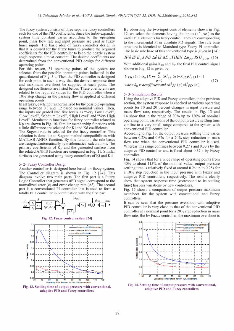
5- 2- Fuzzy Controller DesignAnother controller is designed here based on fuzzy system. The Controller diagram is shown in Fig. 12 [24]. This diagram involve two main parts. The first part is a Fuzzy Logic Controller that generates ûPD signal correspond to the normalized error (ê) and error change rate (Δê). The second part is a conventional PI controller that is used to form a totally PID controller in combination with the first part.
By observing the two-input control elements shown in Fig. 12, we select the elements having the inputs (e ̂ ,Δe ̂) as the useful PID elements for fuzzy control. They are corresponding to the incremental PI or absolute PD signals. The rule base structure is identical to Mamdani-type Fuzzy PI controller. The basic rule base of this conventional type is given in [24]:
With additional gains KPD and KPI the final PID control signal shown in Fig. 12 is given by:
5- 3- Simulation ResultsUsing the adaptive PID and Fuzzy controllers in the previous section, the system response is checked at various operating points for 10 and 20 percent changes in input pressure and mass flow rate, respectively. The results in Fig. 13 and 14 show that in the range of 30% up to 120% of nominal operating point, variations of the output pressure settling time confine to a very small range compared to the system with conventional PID controller. According to Fig. 13, the output pressure settling time varies between 0.28s and 0.67s for a 20% step reduction in mass flow rate when the conventional PID controller is used. Whereas this range confines between 0.27 s and 0.33 s by the adaptive PID controller and is fixed about 0.32 s by Fuzzy controller. Fig. 14 shows that for a wide range of operating points from 40% to about 115% of the nominal value, output pressure settling time is relatively fixed at around 0.2s up to 0.25s for a 10% step reduction in the input pressure with Fuzzy and adaptive PID controllers, respectively. The results clearly show that system response time (correspond to its settling time) has less variations by new controllers.Fig. 15 shows a comparison of output pressure maximum overshoot for the system with conventional and Fuzzy controllers.It can be seen that the pressure overshoot with adaptive PID controller is very close to that of the conventional PID controller at a nominal point for a 20% step reduction in mass flow rate. But by Fuzzy controller, the maximum overshoot is
FLC f (ê ,Δê )
Se
Se
eΔe +
Z-1
KPD
KPI + Su
ûPID uPID ûPD ê
Δê
Fig. 12. Fuzzy control system [24]
Fig. 13. Settling time of output pressure with conventional, adaptive PID and Fuzzy controllers
Fig. 14. Settling time of output pressure with conventional, adaptive PID and Fuzzy controllers
,ˆ ˆ ,i j PD m PDIF e IS E AND e IS E THEN u IS U∆ ∆ ∆ (16)
(17)ˆ ˆ( ) [ ( ) ( ) ]
0ˆ ˆ( ) ( )
nU n S K U q K U nPID u PI PI PD PD
qwhere S is acoefficient and U n U nu PI PD
= ∆ +∑=
∆ =
M. Taleshian Jelodar et al., AUT J. Model. Simul., 49(1)(2017)23-32, DOI: 10.22060/miscj.2016.842
29
almost changed linearly with changes in the operating point.
6- ConclusionsThe turbo-expander system was investigated in this paper focusing on two aspects. The first aspect is the nonlinear behavior of the turbo-expander and the second is the variable nozzle control effect on turbine behavior. By modeling and simulating the turbo-expander system, it was shown that this system is very nonlinear. Linearization of the system has declared that some coefficients of the linearized system are very complicated and dependent on operating point. It is shown that system nonlinearity is such that a conventional PID controller cannot control the nozzle angle and output pressure as well at all operating points. Therefore an adaptive PID controller based on Fuzzy controller and a pure Fuzzy controller were designed for the nonlinear system. It was shown that the system behavior by the new Fuzzy controllers has been improved for a wide range of operating points and different disturbances applied to the system.
Linearized coefficientsLinearization of turbo-expander as (11) gives the below coefficient. The coefficients are calculated using the MATHEMATICA toolbox.
Fig. 15. Maximum overshoot of output pressure with conventional, adaptive PID and Fuzzy controllers
20 p 1 1 1
32 2T 2
K K Q K Ta
K Prθ
= −
1 2 3 2 2b ( K ( 2K K Pr 2K Pr Q T31 0 1 T 1 p 1 1 12 32K PrT 2
Pr Q ( 2K Q T Q ( K T 2T ( K K K X )))))1 1 p 1 1 1 p 1 1 1 p 1 d 0
= − θ
− θ − θ+ − θ+ θ−
K 2 2 30b ( 2K K Pr Pr Q T Q T ( K T32 p T 1 1 1 1 1 1 p 14 32K PrT 2
2 22T ( K K K X )) 2K Pr ( K Q T1 1 p 1 d 0 T 1 p 1 1
Q ( K T K T 2K K T X )))1 1 1 p 1 p 1 1 d 0
θ= θ +θ θ +
θ+ − θ +
θ + θ +
K Q 2 2 20 1b ( 2K K Pr Pr Q 2K Pr ( 2K Q33 p T 1 1 1 T 1 p 14 34K PrT 2
2 2Q ( K 2K K X )) Q ( 2K Q T1 1 p 1 d 0 1 p 1 1
Q ( K T 2T ( K K K X ))))1 p 1 1 1 p 1 d 0
θ= θ − θ +
θ+ +θ θ
+ − θ + θ+
K K Pr0 p 1bp31 Pr2=
2K K Q T0 p 1 1bp32 2K PrT 2
θ=−
2 2K K Q0 p 1bp33 22K PrT 2
θ=−
1 2 4 4a ( K K Q T )( K K Pr31 0 1 1 1 1 T 16 5K PrT 24 4 2Q T ( K K K X )1 1 1 p 1 d 0
4 4K Pr ( 2K K K X )T 2 1 p 1 d 02 2 2 2K Pr Q T ( 2K K K X ))T 1 1 1 1 p 1 d 0
2Pr ( K K K Q T ) Pr1 0 p 1 1 1 12 3K PrT 2
2 2 2 2 2( K K K Q T (Q T 2K Pr ))Q0 p 1 1 1 1 1 T 2 14 3K PrT 2
12( K K K Q ( Q0 p 1 1 12
= θ
+θ θ+
− θ+
− θ θ+
θ+
θ θ +−
θ−
2 2 2 2T K Pr ))T1 T 2 14 3K PrT 2
θ +
M. Taleshian Jelodar et al., AUT J. Model. Simul., 49(1)(2017)23-32, DOI: 10.22060/miscj.2016.842
30
Table 2. The required coefficients for the PID controller at different operating points
References[1] A. Cleveland, “Power Generation with Turbo-expander”,
ASME, 90-DT-2: pp 26-31, 1990.[2] Heinz P. Bloch; Claire Soares, “Turboexpander and
Process Applications”, Gulf Professional Publishing, Boston, 2001.
[3] H. Daneshi H. Khorashadi Zadeh, A. Lotfjou Choobari, “Turboexpander as a distributed generator”, Power and Energy Society General Meeting - Conversion and Delivery of Electrical Energy in the 21st Century: pp 1–7, 2008.
[4] Mehdi Taleshian Jelodar, Hasan Rastegar, Hossein Askarian Abyaneh, “Modeling turbo-expander systems”, SIMULATION, 89(2): pp 234-248, 2013.
[5] M. Taleshian Jelodar, H. Rastegar, M. Pichan, “voltage improvement using a new control strategy for turbo-
expander driving systems”, Electrical Power and Energy Systems, 64: pp 1176–1184, 2015.
[6] Jan Peirs, Dominiek Reynaerts, Filip Verplaetsen, “A microturbine for electric power generation”, Sensors and Actuators A, 113: pp 86–93, 2004.
[7] D. Krähenbühl, C. Zwyssig, H. Weser, J. W. Kolar, “Theoretical and experimental results of a mesoscale electric power generation system from pressurized gas flow”, IOP Publishing, Journal of Micromechanics and Microengineering, 19: pp 1-7, 2009.
[8] Soo-Yong Cho, Chong-Hyun Cho, Chaesil Kim, “Performance characteristics of a turbo expander substituted for expansion valve on air-conditioner” Experimental Thermal and Fluid Science, 32: pp 1655–1665, 2008.
[9] Sylvain Quoilin, Vincent Lemort, Jean Lebrun, “Experimental study and modeling of an Organic Rankine Cycle using scroll expander”, Applied Energy, 87, pp: 1260–1268, 2010.
[10] Vincent Lemort, Sylvain Quoilin, Cristian Cuevas, Jean Lebrun, “Testing and modeling a scroll expander integrated into an Organic Rankine Cycle”, Applied Thermal Engineering, 29, pp 3094–3102, 2009.
[11] Jesse D. Maddaloni, Andrew M. Rowe, Natural gas exergy recovery powering distributed hydrogen production, International Journal of Hydrogen Energy, 32: pp 557–566 ,2007.
[12] Mehdi Babaei Turkemani, Hassan Rastegar, “Modular Modeling of Turbo-Expander Driven Generators for Power System Studies”, IEEJ Transactions on Electrical and Electronic Engineering, IEEJ Trans., 4: pp 645–653, 2009.
[13] Mehdi Babaei Turkemani, Hassan Rastegar, “Flicker Assessment of Turbo-Expander Driven Synchronous Generator in Power Distribution Network”, Journal of Iranian Association of Electrical and Electronics Engineers, 7: pp 53-59, 2010.
[14] M. Taleshian, H. rasregar, H. Askarian, “Modeling and Power Quality Improvement of Turbo-Expander Driving an Induction Generator”, International Journal of Energy Engineering, 2: pp 131-137, 2012.
[15] D. E. Winterbone, N. Munro, P. M. G. Lourtie, “A preliminary study of the design of a Controller for an Automotive Gas Turbine”, Transactions of the ASME, 95: pp 244-250, 1973.
[16] Srithar Rajoo, Ricardo Martinez-Botas, “Variable Geometry Mixed Flow Turbine for Turbochargers: An Experimental Study”, International Journal of Fluid Machinery and Systems, 1: pp 155-168, 2008.
[17] HU Liangjun, YANG Ce, SUN Harold, ZHANG Jizhong, LAI Mingchi, “Numerical Analysis of Nozzle Clearance’s Effect on Turbine Performance”, Chinese Journal of Mech. Engineering, 2010.
[18] A. Romagnoli, R.F. Martinez-Botas, S. Rajoo, “Steady state performance evaluation of variable geometry twin-entry turbine”, International Journal of Heat and Fluid Flow, 32: pp 477-489, 2011.
[19] N. Karamanis, R.F. Martinez-Botas, “Mixed Flow Turbines for Automotive Turbochargers: Steady and unsteady Performance”, IMechE Int. J. Engine Research, 3: pp 127-138, 2002.
M. Taleshian Jelodar et al., AUT J. Model. Simul., 49(1)(2017)23-32, DOI: 10.22060/miscj.2016.842
31
[20] F. Haglind, “Variable geometry gas turbines for improving the part-load performance of marine combined cycles – Gas turbine performance”, Energy, 35: pp 562–570, 2010.
[21] D. H. Cooke, “On Prediction of Off-Design Multistage Turbine Pressures by Stodola’s Ellipse”, Transactions of the ASME, 107: pp 596-606, 1985.
[22] Ali Chaibakhsh, Ali Ghaffari, “Steam turbine model”, Simulation Modelling Practice and Theory, 16: pp 1145–1162, 2008.
[23] A. Mehmood, S. Laghrouche, M. El Bagdouri, “Modeling identification and simulation of pneumatic actuator for VGT system”, Sensors and Actuators A: Physical, 165: pp 367–378, 2010.
[24] George K. I. Mann, Bao-Gang Hu, Raymond G. Gosine, “Analysis of direct action fuzzy PID controller structures”, IEEE TRANSACTIONS ON SYSTEMS, MAN, AND CYBERNETICS—PART B: CYBERNETICS, 29-3: pp 371-388, 1999.
Please cite this article using:
M. Taleshian Jelodar, H. Rastegar, M. Pichan,”Turbo Expander System Behavior Improvement Using an
Adaptive Fuzzy PID Controller”, AUT J. Model. Simul., 49(1)(2017)23-32.