HAL Id: hal-00573278 https://hal.archives-ouvertes.fr/hal-00573278 Submitted on 3 Mar 2011 HAL is a multi-disciplinary open access archive for the deposit and dissemination of sci- entific research documents, whether they are pub- lished or not. The documents may come from teaching and research institutions in France or abroad, or from public or private research centers. L’archive ouverte pluridisciplinaire HAL, est destinée au dépôt et à la diffusion de documents scientifiques de niveau recherche, publiés ou non, émanant des établissements d’enseignement et de recherche français ou étrangers, des laboratoires publics ou privés. Turbo product code decoder without interleaving resource: From parallelism exploration to high effciency architecture Camille Leroux, Christophe Jego, Patrick Adde, Deepak Gupta, Michel Jezequel To cite this version: Camille Leroux, Christophe Jego, Patrick Adde, Deepak Gupta, Michel Jezequel. Turbo product code decoder without interleaving resource: From parallelism exploration to high effciency architecture. Journal of Signal Processing Systems, Springer, 2011, 64 (1), pp.17-29. hal-00573278
Transcript
HAL Id: hal-00573278https://hal.archives-ouvertes.fr/hal-00573278
Submitted on 3 Mar 2011
HAL is a multi-disciplinary open accessarchive for the deposit and dissemination of sci-entific research documents, whether they are pub-lished or not. The documents may come fromteaching and research institutions in France orabroad, or from public or private research centers.
L’archive ouverte pluridisciplinaire HAL, estdestinée au dépôt et à la diffusion de documentsscientifiques de niveau recherche, publiés ou non,émanant des établissements d’enseignement et derecherche français ou étrangers, des laboratoirespublics ou privés.
Turbo product code decoder without interleavingresource: From parallelism exploration to high efficiency
architectureCamille Leroux, Christophe Jego, Patrick Adde, Deepak Gupta, Michel
Jezequel
To cite this version:Camille Leroux, Christophe Jego, Patrick Adde, Deepak Gupta, Michel Jezequel. Turbo product codedecoder without interleaving resource: From parallelism exploration to high efficiency architecture.Journal of Signal Processing Systems, Springer, 2011, 64 (1), pp.17-29. �hal-00573278�
Abstract This article proposes to explore parallelismin Turbo-Product Code (TPC) decoding through a par-allelism level classification and characterization. Fromthis design space exploration, an innovative TPC de-coder architecture without any interleaving resourceis presented. This architecture includes a fully-parallelSISO decoder capable of processing n symbols inone clock period. Syntheses results show the betterefficiency of such an architecture compared with exist-ing solutions. Considering a six-iteration turbo decoderof a BCH(32,26)2 product code, synthesized in 90 nmCMOS technology, 10 Gb/s can be achieved with anarea of 600 Kgates. Moreover, a second architectureenhancing parallelism rate is described. The throughputis 50 Gb/s while an area estimation gives 2.2 Mgates.Finally, comparisons with existing TPC decoders and
This paper was presented in part at the IEEE workshop onSignal Processing Systems, October 8–10, Washington, D.C.Metro Area, U.S.A, 2008.
C. Leroux (B) · C. Jego · P. Adde · D. Gupta · M. JezequelInstitut TELECOM, TELECOM Bretagne, CNRSLab-STICC, UMR 3192, Université Européennede Bretagne, Technopôle Brest-Iroise,83818-29238 Brest Cedex 3, Francee-mail: [email protected]
Nowadays, high throughput telecommunication sys-tems such as optical fiber transmission systems or pas-sive optical networks require powerful error correctingcodes in order to increase their optical budget. Iterativedecoding [1, 2] provides effective solutions for next gen-eration optical systems. Recently, a (660,480) LDPCcode decoder ASIC implementation was proposed. Thethroughput is 2.4 Gb/s while it could be enhanced to10 Gb/s with a (2048,1723) LDPC code [3]. Turboproduct codes [4] also tend to be good candidates foremerging optical systems [5]. In [6], a TPC decoderis included in a 12.4 Gb/s optical experimental setup.Since only a part of the transmitted data is actuallyencoded, the throughput of the TPC turbo decoder is156Mb/s.
The inherent parallel structure of the product codematrix confers to TPC a good ability for parallel decod-ing. Nevertheless, enhancing parallelism rate rapidlyinduces the use of a prohibitive amount of memory.Many solutions were proposed to efficiently exploitparallelism in TPC decoding. However, TPC decodingprovides several level of parallelism and it is not alwaysclear which level is the most efficient.
In [7], we proposed a fully parallel turbo productcode decoder without interleaving resource. In this
J Sign Process Syst
paper, we set this architecture in the more generalcontext of parallelism level exploration. We proposea parallelism level taxonomy that helps to classify andcharacterize parallelism in TPC decoding. Similarly to[8], we provide insights on the benefits that each paral-lelism level can bring to the architecture performance.From this design space exploration, a parallelism levelthat has not been fully used in previous work is iden-tified. Then, we propose an architecture of a highly-parallel TPC decoder that efficiently takes advantageof the exploited parallelism.
After a brief introduction of the TPC coding anddecoding concept in Section 2, Section 3 defines andcharacterizes all the parallelism levels in TPC decoding.In Section 4, a review of existing solutions is givenbefore the description of an innovative TPC decoder ar-chitecture without any interleaving resource. This orig-inal TPC decoder includes a novel fully-parallel SISOdecoder architecture which is described in Section 5.Section 6 gives some synthesis results and demonstratesthe efficiency of the proposed TPC decoder by com-parison with current TPC and LDPC decoders. Theinterconnection issue is assessed and compared with anequivalent LDPC code decoder implementation.
2 TPC Coding and Decoding Principles
Product codes usually have high dimension which pre-cludes Maximum-Likelihood (ML) soft-decision de-coding. Yet, the particular structure of this code familylends itself to an efficient iterative “turbo” decodingalgorithm offering close-to-optimum performance athigh enough Signal-to-Noise-Ratios (SNRs).
2.1 Product Codes
The concept of product codes is a simple and efficientmethod to construct powerful codes with a large min-imum Hamming distance d using cyclic linear blockcodes [9]. Let us consider two systematic cyclic lin-ear block codes C1 having parameters (n1, k1, d1) andC2 having parameters (n2, k2, d2) where ni, ki and di
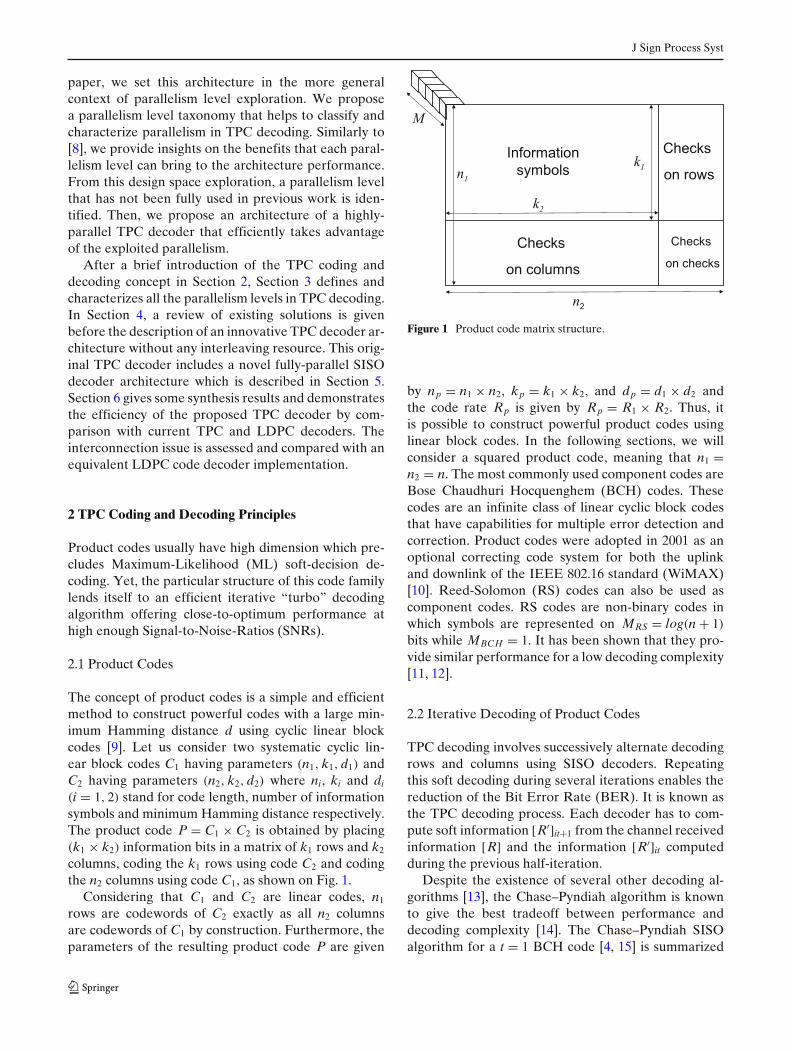
(i = 1, 2) stand for code length, number of informationsymbols and minimum Hamming distance respectively.The product code P = C1 × C2 is obtained by placing(k1 × k2) information bits in a matrix of k1 rows and k2
columns, coding the k1 rows using code C2 and codingthe n2 columns using code C1, as shown on Fig. 1.
Considering that C1 and C2 are linear codes, n1
rows are codewords of C2 exactly as all n2 columnsare codewords of C1 by construction. Furthermore, theparameters of the resulting product code P are given
Figure 1 Product code matrix structure.
by np = n1 × n2, kp = k1 × k2, and dp = d1 × d2 andthe code rate Rp is given by Rp = R1 × R2. Thus, itis possible to construct powerful product codes usinglinear block codes. In the following sections, we willconsider a squared product code, meaning that n1 =n2 = n. The most commonly used component codes areBose Chaudhuri Hocquenghem (BCH) codes. Thesecodes are an infinite class of linear cyclic block codesthat have capabilities for multiple error detection andcorrection. Product codes were adopted in 2001 as anoptional correcting code system for both the uplinkand downlink of the IEEE 802.16 standard (WiMAX)[10]. Reed-Solomon (RS) codes can also be used ascomponent codes. RS codes are non-binary codes inwhich symbols are represented on MRS = log(n + 1)
bits while MBCH = 1. It has been shown that they pro-vide similar performance for a low decoding complexity[11, 12].
2.2 Iterative Decoding of Product Codes
TPC decoding involves successively alternate decodingrows and columns using SISO decoders. Repeatingthis soft decoding during several iterations enables thereduction of the Bit Error Rate (BER). It is known asthe TPC decoding process. Each decoder has to com-pute soft information [R′]it+1 from the channel receivedinformation [R] and the information [R′]it computedduring the previous half-iteration.
Despite the existence of several other decoding al-gorithms [13], the Chase–Pyndiah algorithm is knownto give the best tradeoff between performance anddecoding complexity [14]. The Chase–Pyndiah SISOalgorithm for a t = 1 BCH code [4, 15] is summarized
J Sign Process Syst
below. t represents the maximum number of cor-rectable errors.
1. Search for the L = |λi| least reliable bits from theprevious half-iteration output vector [R′]it such thatmini(|[R′]it|) = λi. mini(.) represents the ith mini-mum function.
2. Compute the syndrome S(t0) of [R′]it,3. Compute the parity of [R′]it,4. Generate τp test patterns τi obtained by inverting
some of the L least reliable bits (τp ≤ 2L).5. For each test pattern (1 ≤ τi ≤ τp − 1)
– Compute the syndrome S(τi),– Correct the potential error by inverting the bit
position S(τi),– Recompute the parity considering the detec-
tion of an error and the parity of [R′]it,– Compute the square Euclidian distance (met-
ric) Mi between [R′]it and the considered testpattern τi.
6. Select the Decided Word (DW) among test pat-terns having the minimal metric (MDW) and chooseCw competitors codewords ci (1 < i < Cw) havingthe second minimum metric.
7. For each symbol of the DW,
– Compute the new reliability Fit:
Fit =
⎧⎪⎪⎪⎪⎪⎪⎨
⎪⎪⎪⎪⎪⎪⎩
βit = (|R′it| +
∑L
i=1λi)
− min(Mi) when no competitor exists
Fit = min2(Mi) − min(Mi) otherwise,
– Compute extrinsic information Wit = Fit − R′it,
– Add extrinsic information (multiplied by αit) tothe channel received word, R′
it+1 = R + αitWit.
As explained in [16], decoding parameters L, τp,Cw and the number of quantization bits of the softinformation q have a considerable effect on decodingperformance and complexity. The αit coefficient allowsdecoding decisions to be damped during the first iter-ations. βit is an estimation of Fit when no competitorexists. As detailed in [17], it is based on the least reliablebits value.
3 Parallel Processing Levels in TPC Decoding
An architecture can be characterized by different met-rics such as throughput, latency, hardware complex-ity, power consumption, routing density, etc. In this
study, we aim at high speed architectures with lowhardware complexity. Consequently, the performanceis measured by throughput (T) while the cost functionis the hardware complexity (C). In such a context, theefficiency of an architecture is defined as the through-put/complexity ratio : E = T/C. An efficient architec-ture would process a high data rate at a low hardwarecomplexity.
The parallelism of an architecture can be defined as“the ability of the system to process several data in paral-lel”. We formerly define the parallelism P of a decoderas the number of bit that can be processed/decoded ina single clock cycle. Parallelism directly influences theperformance of an architecture. In order to quantifythe benefit/disadvantage brought by the application ofa parallelism Pi to an architecture, we define threemetrics, the speed gain GS, the computational ratio RC
and the ef f iciency gain GE:⎧⎪⎪⎪⎪⎪⎪⎪⎪⎨
⎪⎪⎪⎪⎪⎪⎪⎪⎩
GS(Pi = p) = TPi=p
TPi=1
RC(Pi = p) = CPi=p
CPi=1
GE(Pi = p) = EPi=p
EPi=1= GS(Pi=p)
RC(Pi=p)
A parallelism level Pi is considered to be ef fective ifGS(Pi) > 1, while it is ef f icient when GE(Pi) > 1 ⇐⇒GS(Pi) > RC(Pi). In the following of this section, allparallelism levels in TPC decoding are detailed andcharacterized.
3.1 Frame Parallelism
The highest level of parallelism can be observed at theframe level, this is known as frame parallelism. It is aform of spatial parallelism and is suitable to any de-coding scheme. It consists in duplicating the processingresources, e.g. the turbo-decoder. By using this paral-lelism level in TPC decoding, P frame matrices can bedecoded at the same time. Considering P frame turbo-decoders that have the same throughput T0, the speedgain and complexity ratio are equivalent: GS = RC =P frame. Consequently the efficiency does not increasewith P frame: GE = 1. Actually, this level of parallelismis only limited by the affordable silicon area. Althoughframe parallelism do make TPC decoder architecturemore effective, it does not improve its efficiency.
3.2 Iteration Parallelism
In a sequential TPC decoder implementation, eachiteration is performed by the same decoder that reads
J Sign Process Syst
and writes data in the Interleaving Memories (IM). Itis however possible to use the iteration parallelism byduplicating the elementary decoder in a pipelined struc-ture. The maximum depth of such a structure equals tothe maximum number of iteration itmax. Iteration par-allelism is a type of temporal parallelism. Here again,the throughput benefit equals to the complexity ratio:GS = RC = Pit. It means that the iteration parallelismdoes not improve efficiency.
3.3 Sub-block Parallelism
In a product code matrix, each row (column) is ob-tained independently from the others (See Section 2.1).This interesting property can also be used during thedecoding process, where each row (column) is decodedindependently. In an implementation prospective, itmeans that more than one decoder can be assigned torow (column) decoding. Considering a product codematrix of size n2, a maximum number of n decoders canbe duplicated for row (column) decoding. We designatethis parallelism level as sub-block parallelism Psb . Ina straightforward application of this parallelism level,one would simply duplicate the SISO decoders and theassociated memory resources. It leads to a non-efficientparallelism exploitation, in particular due to the largesize of the memory blocks that have to be duplicatedPsb times. In [18, 19] solutions are proposed to avoidinterleaving resource duplication when Psb increases.This makes the complexity ratio lower than the speedgain, which means that the ef f iciency gain of the archi-tecture increases with Psb . GE can be expressed as:
GE = Psb (CSISO + Cπ )
Psb CSISO + Cπ
GE > 1 ⇐⇒ Psb > 1
CSISO and Cπ are the hardware complexity ofthe SISO decoder and the interleaving resourcerespectively.
3.4 Symbol Parallelism
A finer-grained parallelism is the symbol parallelism.It can be defined as the ability of a SISO decoder,to process Psym symbols of the same sub-block (rowor column) in parallel. In a sequential SISO decoder,input data is shifted in a serial manner. Every in-coming symbol implies some internal metrics to beupdated. By increasing Psym, some parts of the de-coder datapath has to be duplicated, (e.g. the relia-bility computation stage). However, the other blocks,such as the test pattern metric computation, or the
competitor vector determination block, remain identi-cal when Psym increases. Consequently, the complexityratio is lower than the speed gain: GE < 1. Increas-ing Psym also means that the interleaving memoryshould be able to read/write more than one data duringthe same clock cycle. Solutions were provided in [20]to exploit this parallelism while avoiding interleavingmemory duplication. Synthesis results confirm that theefficiency increases with Psym. For an architecture thatavoid interleaving resource duplication, GE can be ex-pressed as:
GE > 1 ⇐⇒ CDEC(Psym = p) < p × CDEC(Psym = 1)
CDEC(Psym = p) is the hardware complexity of aSISO decoder with a symbol parallelism equals to p.In [20], this inequality has been verified by synthesisfor Psym = {1; 2; 4; 8} for a BCH(32,26)2 TPC decoder.In this paper, we propose to verify this inequality forthe same code and for Psym = n = 32. This challengingarchitecture is described in Section 5.
3.5 Intra-symbol Parallelism
In TPC decoding, BCH codes are often used for theirgood decoding performance/complexity tradeoff. Re-cent work [11, 21] has shown that using RS codes ascomponent codes, can provide similar decoding perfor-mance at a reasonable computational complexity.
From an architectural point of view, the non-binarystructure of RS codes enables to exploit an extra par-allelism level, the intra-symbol parallelism Pis. In a RScode of size n, a symbol consists in log(n + 1) bits (seeFig. 1). A RS-SISO decoder can either shift-in symbolsbit by bit or symbol by symbol. It provides a maximalparallelism rate of max(Pis) = log(n + 1).
Similarly to the symbol parallelism, the resourcesharing within the RS-SISO decoder increases theefficiency. However the ef f iciency gain provided by Pis
is hard to estimate because it is highly related to theinternal architecture of the SISO decoder. Neverthe-less, it is possible to give a condition that guaranteesGE(Pis) > 1:
C(Pis > 1) < Pis × C(Pis = 1)
3.6 Parallelism Levels Comparison
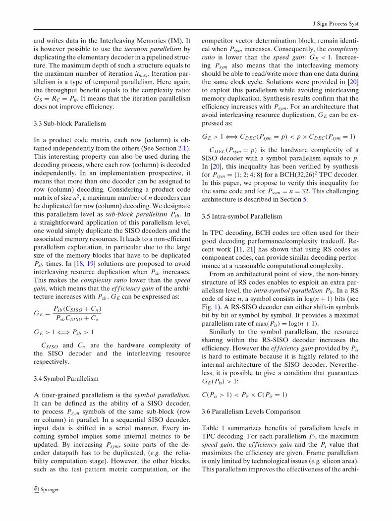
Table 1 summarizes benefits of parallelism levels inTPC decoding. For each parallelism Pi, the maximumspeed gain, the ef f iciency gain and the Pi value thatmaximizes the efficiency are given. Frame parallelismis only limited by technological issues (e.g. silicon area).This parallelism improves the effectiveness of the archi-
J Sign Process Syst
Table 1 Comparison of parallelism levels in TPC decoding.
Pi max(GS) GE arg(max(E))
P frame ∞ � 1 [0;+∞[Pit ITc � 1 ITc
Psb n ≥ 1 nPsym n ≥ 1 nPis log(n + 1) ≥ 1 log(n + 1)
tecture; it is straightforward to implement but it doesnot improve efficiency. Iteration parallelism has thesame impact but has an upper bound limited by themaximum number of iteration required by the decodingprocess.
Application of lower levels of parallelism (Psb , Psym
and Pis) improves the architecture efficiency. It is evenmaximized for highest parallelism value. However, theuse of these parallelism levels is not as straightforwardas P frame and Pit. It requires some specific schedulingand/or implementation strategies.
4 Parallel Decoding of Product Codes
Designing turbo-decoder architectures compatible withdata rates higher than 10 Gb/s is a challenging issue.In this section we first introduce previous work. Then,the proposed Interleaving-Memory-free (IM-free) TPCdecoder architecture is detailed. It jointly uses Psym andPsb and includes fully-parallel SISO decoders that aredescribed in Section 5.
4.1 Previous Work
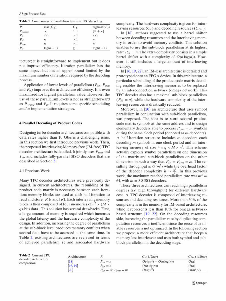
Many TPC decoder architectures were previously de-signed. In current architectures, the rebuilding of theproduct code matrix is necessary between each itera-tion: memory blocks are used at each half-iteration toread and store [R′]it and [R]. Each interleaving memoryblock is then composed of four memories of n2 × (M ×q)-bits data . This solution has several drawbacks. First,a large amount of memory is required which increasesthe global latency and the hardware complexity of thedesign. In addition, increasing the degree of parallelismat the sub-block level produces memory conflicts whenseveral data have to be accessed at the same time. InTable 2, existing architectures are reviewed in termsof achieved parallelism Pi and associated hardware
complexity. The hardware complexity is given for inter-leaving resources (Cπ ) and decoding resources (CDec).
In [18], authors suggested to use a barrel shifterbetween decoding resources and the interleaving mem-ory in order to avoid memory conflicts. This solutionenables to use the sub-block parallelism at its highestrate: Psb = n. The extra-complexity consists in a simplebarrel shifter with a complexity of O(n log(n)). How-ever, it still includes a large amount of interleavingmemory.
In [16, 19, 22], an IM-less architecture is detailed andprototyped onto an FPGA device. In this architecture, aparticular scheduling of the product code matrix decod-ing enables the interleaving memories to be replacedby an interconnection network (omega network). ThisTPC decoder also has a maximal sub-block parallelism(Psb = n), while the hardware complexity of the inter-leaving resources is drastically reduced.
Moreover, in [20] an architecture that uses symbolparallelism in conjunction with sub-block parallelism,was proposed. The idea is to store several productcode matrix symbols at the same address and to designelementary decoders able to process Psym = m symbolsduring the same clock period (denoted as m-decoders).A half-iteration structure includes m decoders eachdecoding m symbols in one clock period and an inter-leaving memory of size 4 × q × M × n2. This schemeactually exploits symbol parallelism on one dimensionof the matrix and sub-block parallelism on the otherdimension in such a way that Psb = Psym = m. The re-sulting throughput is O(m2) while the overhead factorof the decoder complexity is ∼ m2
2 . In this previouswork, the maximum reached parallelism rate was m2 =64, with m = 8 SISO decoders.
These three architectures can reach high parallelismdegrees (i.e. high throughput) for different hardwarecost. A TPC decoder is composed of interleaving re-sources and decoding resources. More than 50% of thecomplexity is in the memory for IM-based architecture,while it represents less than 10% for omega network-based structure [19, 22]. On the decoding resourcesside, increasing the parallelism rate by duplicating com-putation resources is inefficient since the reuse of avail-able resources is not optimized. In the following sectionwe propose a more efficient architecture that keeps amemory-less interleaver and uses both symbol and sub-block parallelism in the decoding stage.
Table 2 Current TPCdecoder architecturecomparison.
Architecture Pi Cπ (1/2iter) CDec(1/2iter)
[18] Psb = n O(4qn2) + O(n log(n)) O(n)
[16, 19] Psb = n O(n log(n)) O(n)
[20] Psb = m; Psym = m O(4qn2) O(m2/2)
J Sign Process Syst
Figure 2 Proposed parallel decoding scheduling of a productcode matrix.
Considering that one can design a Psym = n SISO de-coder, a product code matrix can be decoded withoutany interleaving resource as shown in Fig. 2.
At t = 0, the fully-parallel SISO decoder processesthe column 1. During the next clock period, n se-quential SISO decoders (Psym = 1) start decoding thefirst symbol of each row while the parallel decoderprocess the column 2. During the nth clock period, se-quential decoders complete matrix decoding while theparallel decoder is already decoding the next matrix.
Figure 3 Previous TPC decoder architecture (a) and proposedfully-parallel SISO based TPC decoder architecture (b).
Data generated by the parallel decoder is immediatelyused by a sequential decoder. Consequently, no IM ordata routing resources are required between the fully-parallel decoder and sequential decoders. The resultingproposed architecture and the previous architectures[18, 19] for one iteration are depicted on Fig. 3.
This architecture uses row-wise Psb and column-wisePsym. More specifically, we have:
One should notice that Psb (col) = Psym(row) can befurther exploited.
4.3 Towards a Maximal Parallelism Rate
Starting from the IM-free architecture presented in theprevious section, parallelism can be further enhanced.Figure 4 shows the alternate product code matrix par-allel decoding scheme in which Psb (col) = Psym(row) =m and Psym(col) = Psb (row) = n. The TPC decoderconsists in m× n-decoders for column decoding andn× m-decoders for row decoding. A m-decoder canprocess m symbols in one clock period and 1 ≤ m ≤n. In such an architecture, the maximum reachableparallelism rate P = n2 can be achieved by using nfully-parallel SISO decoders for column decoding andn fully-parallel SISO decoders for row decoding. Intra-symbol parallelism can also be used to increase thetotal parallelism to P = Psb × Psym × Pis = n2 log(n).
Figure 4 Alternative turbo decoding scheduling for enhancedparallelism rate.
J Sign Process Syst
All these new schemes however require to design aSISO decoder capable of processing n symbols in oneclock period.
5 Architecture of a Fully-Parallel Combinatory SISODecoder
The proposed IM-free TPC decoder architecture re-quires a fully-parallel combinatorial SISO decoder. Tothe best of our knowledge, only sequential SISO de-coders able to process m ≤ n symbols in one clockperiod have been previously designed. The design of afully-parallel combinatorial SISO decoder is a challeng-ing issue for designer. In the following section, such anarchitecture is proposed and described.
5.1 Algorithmic Parameter Reduction
As explained earlier in Section 2, the Chase–Pyndiahalgorithm includes parameters (L, τp, Cw, q) whichimpact on both the performance and the complex-ity of the turbo decoding. BER simulation were per-formed with different parameters: L = {2; 3; 4; 5}, τp ={4; 8; 16}, Cw = {0; 1; 2; 3}, q = {3; 4; 5}. Performingeight iterations, the parameter set P0 = {L = 5, τp =16, Cw = 3, q = 5} gives the best performance for amaximal complexity [14]. However, algorithmic simula-tions showed that the reduced parameter set P1 = {L =3, τp = 8, Cw = 0, q = 5} only induce a performanceloss of 0.25dB at BER= 10−6 while it becomes nullbelow BER = 10−9. Further reducing these parameterswould induce a notable performance loss. For exam-ple by simply reducing the number of test patterns:P2 = {L = 2, τp = 4, Cw = 3, q = 5}, the performanceloss reaches 0.5dB. Consequently, using P1 enables thearchitecture to be simplified at very low performancelost below BER=10−9.
Figure 5 Combinatorial version of the fully-parallel SISOdecoder.
5.2 Fully-Parallel SISO Decoder Architecture
Figure 5 depicts the architecture of the fully-parallelSISO decoder. In the first attempt a purely combinato-rial designed was conceived. Later, a critical path studymandated the insertion of pipeline stages within thestructure. The SISO decoder is split in three stages,namely the reception stage, the test pattern processingstage and the soft output computation stage.
5.2.1 Reception Stage
The reception stage corresponds to steps (1–3) of theChase–Pyndiah algorithm detailed in Section 2.
The syndrome of the incoming vector R′it can be
derived as S(R′it) = H × sign(R′
it) where H is the paritycheck matrix of the BCH code. A straightforward im-plementation of such a matrix multiplication is depictedon Fig. 6. The H matrix, the corresponding parity checkequations and the syndrome S(t0) = [s2, s1, s0] imple-mentation of a BCH(7,4) code are detailed.
It can be noticed that some parity check equationshave similar terms. For instance, the term (x1 ⊕ x0) isused in both s1 and s2 computation. This enables a reuseof computation resources for an even more efficientimplementation. The parity of the incoming vector R′
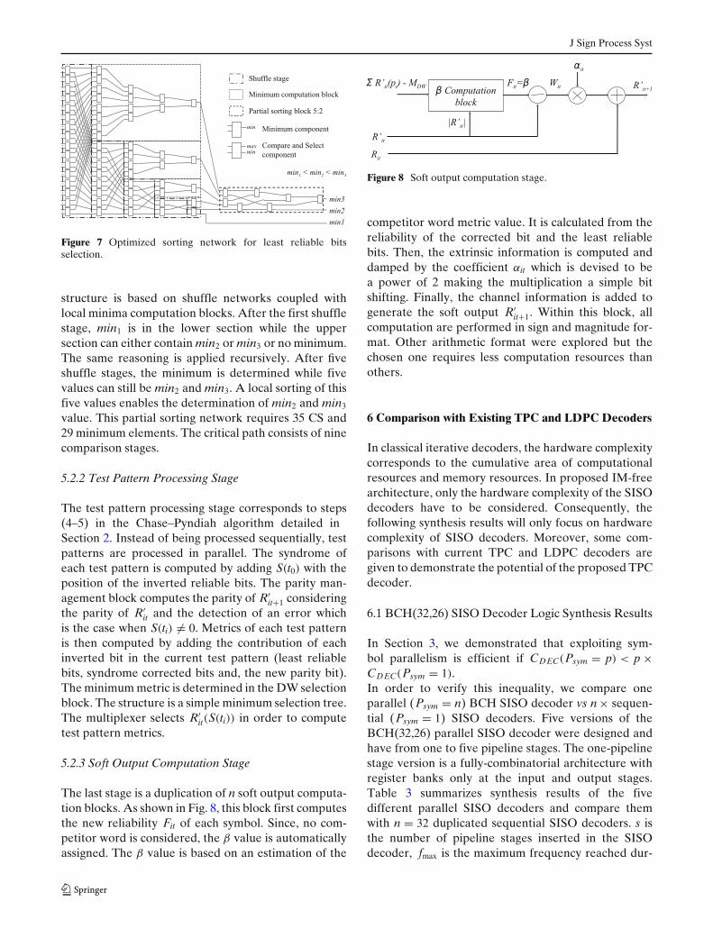
itis computed with a similar structure by “xoring” (n − 1)incoming bits. Selecting the least reliable bits amongthe incoming vector in parallel requires a sorting net-work. Such structures are composed of interconnectedCompare and Select operators (CS). The interconnec-tion scheme depends on the considered sorting algo-rithm. Many parallel sorting algorithm are conceivable[23]. However, most of them are optimized for a com-plete sorting, while the Chase–Pyndiah algorithm onlyrequires a partial sorting (i.e. extracting L minima).Consequently we devised a network optimized, in termsof area and critical path, for the partial sorting of L =3 values among n = 32, as depicted on Fig. 7. The
Figure 6 BCH(7,4) code: a Parity check matrix b Parity checkequations c Syndrome parallel computation implementation.
J Sign Process Syst
Figure 7 Optimized sorting network for least reliable bitsselection.
structure is based on shuffle networks coupled withlocal minima computation blocks. After the first shufflestage, min1 is in the lower section while the uppersection can either contain min2 or min3 or no minimum.The same reasoning is applied recursively. After fiveshuffle stages, the minimum is determined while fivevalues can still be min2 and min3. A local sorting of thisfive values enables the determination of min2 and min3
value. This partial sorting network requires 35 CS and29 minimum elements. The critical path consists of ninecomparison stages.
5.2.2 Test Pattern Processing Stage
The test pattern processing stage corresponds to steps(4–5) in the Chase–Pyndiah algorithm detailed inSection 2. Instead of being processed sequentially, testpatterns are processed in parallel. The syndrome ofeach test pattern is computed by adding S(t0) with theposition of the inverted reliable bits. The parity man-agement block computes the parity of R′
it+1 consideringthe parity of R′
it and the detection of an error whichis the case when S(ti) �= 0. Metrics of each test patternis then computed by adding the contribution of eachinverted bit in the current test pattern (least reliablebits, syndrome corrected bits and, the new parity bit).The minimum metric is determined in the DW selectionblock. The structure is a simple minimum selection tree.The multiplexer selects R′
it(S(ti)) in order to computetest pattern metrics.
5.2.3 Soft Output Computation Stage
The last stage is a duplication of n soft output computa-tion blocks. As shown in Fig. 8, this block first computesthe new reliability Fit of each symbol. Since, no com-petitor word is considered, the β value is automaticallyassigned. The β value is based on an estimation of the
Figure 8 Soft output computation stage.
competitor word metric value. It is calculated from thereliability of the corrected bit and the least reliablebits. Then, the extrinsic information is computed anddamped by the coefficient αit which is devised to bea power of 2 making the multiplication a simple bitshifting. Finally, the channel information is added togenerate the soft output R′
it+1. Within this block, allcomputation are performed in sign and magnitude for-mat. Other arithmetic format were explored but thechosen one requires less computation resources thanothers.
6 Comparison with Existing TPC and LDPC Decoders
In classical iterative decoders, the hardware complexitycorresponds to the cumulative area of computationalresources and memory resources. In proposed IM-freearchitecture, only the hardware complexity of the SISOdecoders have to be considered. Consequently, thefollowing synthesis results will only focus on hardwarecomplexity of SISO decoders. Moreover, some com-parisons with current TPC and LDPC decoders aregiven to demonstrate the potential of the proposed TPCdecoder.
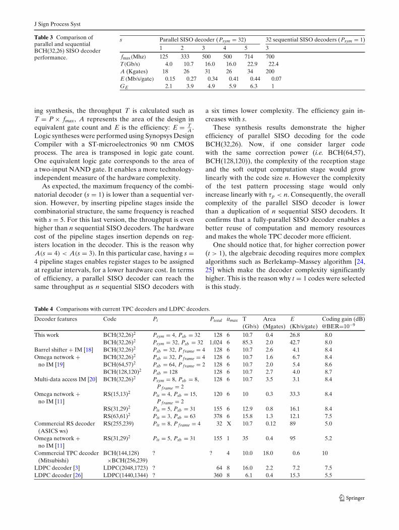
In Section 3, we demonstrated that exploiting sym-bol parallelism is efficient if CDEC(Psym = p) < p ×CDEC(Psym = 1).In order to verify this inequality, we compare oneparallel (Psym = n) BCH SISO decoder vs n × sequen-tial (Psym = 1) SISO decoders. Five versions of theBCH(32,26) parallel SISO decoder were designed andhave from one to five pipeline stages. The one-pipelinestage version is a fully-combinatorial architecture withregister banks only at the input and output stages.Table 3 summarizes synthesis results of the fivedifferent parallel SISO decoders and compare themwith n = 32 duplicated sequential SISO decoders. s isthe number of pipeline stages inserted in the SISOdecoder, fmax is the maximum frequency reached dur-
J Sign Process Syst
Table 3 Comparison ofparallel and sequentialBCH(32,26) SISO decoderperformance.
ing synthesis, the throughput T is calculated such asT = P × fmax, A represents the area of the design inequivalent gate count and E is the efficiency: E = T
A .Logic syntheses were performed using Synopsys DesignCompiler with a ST-microelectronics 90 nm CMOSprocess. The area is transposed in logic gate count.One equivalent logic gate corresponds to the area ofa two-input NAND gate. It enables a more technology-independent measure of the hardware complexity.
As expected, the maximum frequency of the combi-natorial decoder (s = 1) is lower than a sequential ver-sion. However, by inserting pipeline stages inside thecombinatorial structure, the same frequency is reachedwith s = 5. For this last version, the throughput is evenhigher than n sequential SISO decoders. The hardwarecost of the pipeline stages insertion depends on reg-isters location in the decoder. This is the reason whyA(s = 4) < A(s = 3). In this particular case, having s =4 pipeline stages enables register stages to be assignedat regular intervals, for a lower hardware cost. In termsof efficiency, a parallel SISO decoder can reach thesame throughput as n sequential SISO decoders with
a six times lower complexity. The efficiency gain in-creases with s.
These synthesis results demonstrate the higherefficiency of parallel SISO decoding for the codeBCH(32,26). Now, if one consider larger codewith the same correction power (i.e. BCH(64,57),BCH(128,120)), the complexity of the reception stageand the soft output computation stage would growlinearly with the code size n. However the complexityof the test pattern processing stage would onlyincrease linearly with τp < n. Consequently, the overallcomplexity of the parallel SISO decoder is lowerthan a duplication of n sequential SISO decoders. Itconfirms that a fully-parallel SISO decoder enables abetter reuse of computation and memory resourcesand makes the whole TPC decoder more efficient.
One should notice that, for higher correction power(t > 1), the algebraic decoding requires more complexalgorithms such as Berlekamp–Massey algorithm [24,25] which make the decoder complexity significantlyhigher. This is the reason why t = 1 codes were selectedis this study.
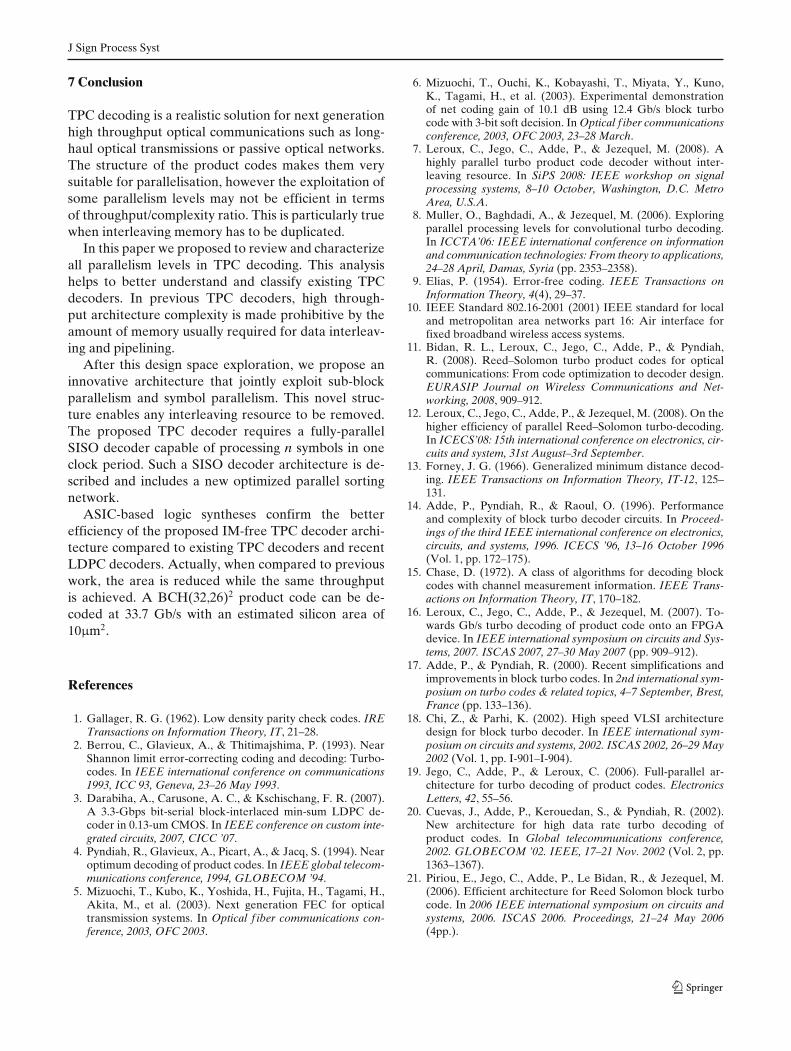
Table 4 Comparisons with current TPC decoders and LDPC decoders.
Decoder features Code Pi Ptotal itmax T Area E Coding gain (dB)(Gb/s) (Mgates) (Kb/s/gate) @BER=10−9
6.2 Comparison with Existing TPC DecoderArchitectures
Table 4 compares performance of the proposed so-lution with current architectures in a ultra-high-throughput context (T > 10 Gb/s). For each solution,the decoder architecture main features, the targetedcode, the levels of parallelism that were used in orderto reach T = 10 Gb/s, the resulting total parallelism(Ptotal = ∏
i Pi), the maximum number of iteration itmax
are given. We consider that one iteration is actuallyimplemented. The resulting throughput is T = Ptotal ×fmax/ itmax. Finally, the gate count (A), the efficiency(E = T/A) and the achieved coding gain at BER=10−9
are given. Such a low BER is usually targeted in veryhigh speed application (e.g. data transmission over Pas-sive Optical Networks).
For a fair comparison, architectures described in [11,18–20] were synthesized with the same technology: STMicroelectronics, CMOS 90 nm with a target frequencyfmax = 500 MHz. For the remaining architectures, wegathered information from the published papers andtechnical reports.
Two versions of the proposed turbo decoder weresynthesized. The first one consists in 4 parallel SISOdecoders together with 32 Psym = 4-SISO decoders.The reached throughput is then sufficient for 10 Gb/sapplications. The second version uses only fully-parallelSISO decoder, 32 of such decoders are duplicatedfor each half-iteration. The maximum throughput is85 Gb/s for the best efficiency.
The barrel-shifter-based solution [18] can achieve10 Gb/s with 2.6 Mgates. In order to reach a sufficientparallelism level, it was necessary to use frame paral-lelism. The efficiency of this solution is six times lowerthan the proposed architecture. This low efficiency ismainly due to the use of interleaving memory.
For the same reason, the TPC decoder with multi-access data [20] has a low efficiency and also requiresthe use of frame parallelism to achieve 10 Gb/s.
In [19], the elimination of interleaving memoriesimproves the efficiency but the maximum parallelismrate is limited by the code size n, which makes the useof frame parallelism mandatory in a ultra high speedcontext. However, the proposed solution provides amaximum parallelism rate of n2.
The study in [11] shows that RS-TPC are a practicalsolution for 10 Gb/s transmission over optical networks.As we mentioned in Section 3, using RS codes enablesthe use of intra-symbol parallelism. With an omega-network-based architecture, this solution also presentsgood efficiency gain for similar decoding performance.
One should notice that the proposed fully-parallel ar-chitecture is applicable to RS decoding as well. Weexpect that the application of intra-symbol parallelismwould further increase the overall efficiency of the TPCdecoder. Moreover. when comparing a single iterationof RS-TPC decoding with a commercial RS(255,239)code decoder, one can observe that superior efficiencyis achieved for slightly better decoding performance.
Mitsubishi has recently proposed a TPC decoder for10 Gb/s optical transmissions. The component code is aBCH(144,128)×BCH(256,239). These codes are morepowerful than t = 1 BCH codes that are used in thisstudy, however the implementation is very costly interms of hardware complexity. Indeed, 18 Mgates arenecessary to implement such a decoder, which makesthe efficiency very small. This is the cost that have to bepaid for a 2dB extra coding gain provided by this TPCdecoder.
6.3 Comparison with Current LDPC Decoders
As a matter of comparison, we gathered results fromrecent academic implementation of LDPC decoders.Since the code rates are different, the decoding per-formance comparison is not straightforward. Howeverthe architectural results help to locate the different de-coders in the design space. Synthesis results show that afully-parallel TPC decoder achieves higher throughput(85 Gb/s) than comparable LDPC decoders with alower hardware complexity (2 Mgates).
However, placing and routing 2n parallel SISO de-coders onto the same chip would reduce the maximumworking frequency of the parallel SISO decoder. Nev-ertheless, with Ptotal =1,024, throughput T=10 Gb/s isreached when f > 88 MHz which is a most probablyachievable frequency on an ASIC target. Furthermore,a reasonable working frequency of f =300 MHz leadsto a BCH(32,26)2 product code turbo decoder withan throughput T =50 Gb/s. The total area of such aparallel turbo decoder is A = 2.2 Mgates= 10 μm2.In parallel LDPC code decoder, one of the main is-sues is the routing congestion induced by the Tan-ner graph implementation. The number of intercon-nections among the TPC decoder is In(TPCD) = 2 ×n2
BCH × q while an equivalent fully parallel 1024-LDPCdecoder would have In(1024-LDPC) = nLDPC × q × dv
where dv represents the variable node degree. Con-sequently, as long as dv > 2, the following inequa-tion is verified: In(T PCD) < In(1024 − LDPC). Con-sequently, despite the high parallelism level that canbe reached in TPC decoding, both area and routingcongestions are in favor of TPC decoders.
J Sign Process Syst
7 Conclusion
TPC decoding is a realistic solution for next generationhigh throughput optical communications such as long-haul optical transmissions or passive optical networks.The structure of the product codes makes them verysuitable for parallelisation, however the exploitation ofsome parallelism levels may not be efficient in termsof throughput/complexity ratio. This is particularly truewhen interleaving memory has to be duplicated.
In this paper we proposed to review and characterizeall parallelism levels in TPC decoding. This analysishelps to better understand and classify existing TPCdecoders. In previous TPC decoders, high through-put architecture complexity is made prohibitive by theamount of memory usually required for data interleav-ing and pipelining.
After this design space exploration, we propose aninnovative architecture that jointly exploit sub-blockparallelism and symbol parallelism. This novel struc-ture enables any interleaving resource to be removed.The proposed TPC decoder requires a fully-parallelSISO decoder capable of processing n symbols in oneclock period. Such a SISO decoder architecture is de-scribed and includes a new optimized parallel sortingnetwork.
ASIC-based logic syntheses confirm the betterefficiency of the proposed IM-free TPC decoder archi-tecture compared to existing TPC decoders and recentLDPC decoders. Actually, when compared to previouswork, the area is reduced while the same throughputis achieved. A BCH(32,26)2 product code can be de-coded at 33.7 Gb/s with an estimated silicon area of10μm2.
References
1. Gallager, R. G. (1962). Low density parity check codes. IRETransactions on Information Theory, IT, 21–28.
2. Berrou, C., Glavieux, A., & Thitimajshima, P. (1993). NearShannon limit error-correcting coding and decoding: Turbo-codes. In IEEE international conference on communications1993, ICC 93, Geneva, 23–26 May 1993.
3. Darabiha, A., Carusone, A. C., & Kschischang, F. R. (2007).A 3.3-Gbps bit-serial block-interlaced min-sum LDPC de-coder in 0.13-um CMOS. In IEEE conference on custom inte-grated circuits, 2007, CICC ’07.
4. Pyndiah, R., Glavieux, A., Picart, A., & Jacq, S. (1994). Nearoptimum decoding of product codes. In IEEE global telecom-munications conference, 1994, GLOBECOM ’94.
5. Mizuochi, T., Kubo, K., Yoshida, H., Fujita, H., Tagami, H.,Akita, M., et al. (2003). Next generation FEC for opticaltransmission systems. In Optical f iber communications con-ference, 2003, OFC 2003.
6. Mizuochi, T., Ouchi, K., Kobayashi, T., Miyata, Y., Kuno,K., Tagami, H., et al. (2003). Experimental demonstrationof net coding gain of 10.1 dB using 12.4 Gb/s block turbocode with 3-bit soft decision. In Optical f iber communicationsconference, 2003, OFC 2003, 23–28 March.
7. Leroux, C., Jego, C., Adde, P., & Jezequel, M. (2008). Ahighly parallel turbo product code decoder without inter-leaving resource. In SiPS 2008: IEEE workshop on signalprocessing systems, 8–10 October, Washington, D.C. MetroArea, U.S.A.
8. Muller, O., Baghdadi, A., & Jezequel, M. (2006). Exploringparallel processing levels for convolutional turbo decoding.In ICCTA’06: IEEE international conference on informationand communication technologies: From theory to applications,24–28 April, Damas, Syria (pp. 2353–2358).
10. IEEE Standard 802.16-2001 (2001) IEEE standard for localand metropolitan area networks part 16: Air interface forfixed broadband wireless access systems.
11. Bidan, R. L., Leroux, C., Jego, C., Adde, P., & Pyndiah,R. (2008). Reed–Solomon turbo product codes for opticalcommunications: From code optimization to decoder design.EURASIP Journal on Wireless Communications and Net-working, 2008, 909–912.
12. Leroux, C., Jego, C., Adde, P., & Jezequel, M. (2008). On thehigher efficiency of parallel Reed–Solomon turbo-decoding.In ICECS’08: 15th international conference on electronics, cir-cuits and system, 31st August–3rd September.
13. Forney, J. G. (1966). Generalized minimum distance decod-ing. IEEE Transactions on Information Theory, IT-12, 125–131.
14. Adde, P., Pyndiah, R., & Raoul, O. (1996). Performanceand complexity of block turbo decoder circuits. In Proceed-ings of the third IEEE international conference on electronics,circuits, and systems, 1996. ICECS ’96, 13–16 October 1996(Vol. 1, pp. 172–175).
15. Chase, D. (1972). A class of algorithms for decoding blockcodes with channel measurement information. IEEE Trans-actions on Information Theory, IT, 170–182.
16. Leroux, C., Jego, C., Adde, P., & Jezequel, M. (2007). To-wards Gb/s turbo decoding of product code onto an FPGAdevice. In IEEE international symposium on circuits and Sys-tems, 2007. ISCAS 2007, 27–30 May 2007 (pp. 909–912).
17. Adde, P., & Pyndiah, R. (2000). Recent simplifications andimprovements in block turbo codes. In 2nd international sym-posium on turbo codes & related topics, 4–7 September, Brest,France (pp. 133–136).
18. Chi, Z., & Parhi, K. (2002). High speed VLSI architecturedesign for block turbo decoder. In IEEE international sym-posium on circuits and systems, 2002. ISCAS 2002, 26–29 May2002 (Vol. 1, pp. I-901–I-904).
19. Jego, C., Adde, P., & Leroux, C. (2006). Full-parallel ar-chitecture for turbo decoding of product codes. ElectronicsLetters, 42, 55–56.
20. Cuevas, J., Adde, P., Kerouedan, S., & Pyndiah, R. (2002).New architecture for high data rate turbo decoding ofproduct codes. In Global telecommunications conference,2002. GLOBECOM ’02. IEEE, 17–21 Nov. 2002 (Vol. 2, pp.1363–1367).
21. Piriou, E., Jego, C., Adde, P., Le Bidan, R., & Jezequel, M.(2006). Efficient architecture for Reed Solomon block turbocode. In 2006 IEEE international symposium on circuits andsystems, 2006. ISCAS 2006. Proceedings, 21–24 May 2006(4pp.).
J Sign Process Syst
22. Leroux, C., Jego, C., Adde, P., & Jezequel, M. (2009). High-throughput block turbo decoding: From full-parallel archi-tecture to FPGA prototyping. Journal of Signal ProcessingSystems, 57, 349–361.
23. Akl, S. G. (1985). Parallel sorting algorithms. New York:Academic.
24. Berlekamp, E. R. (1984). Algebraic coding theory, revisededition. Laguna Hills: Aegean.
25. Massey, J. L. (1969). Shift-register synthesis and bch decod-ing. IEEE Transactions on Information Theory, IT, 122–127.
26. Yamagishi, H., & Noda, M. (2008). High throughput hard-ware architecture for (1440,1344) low-density parity-checkcode utilizing quasi-cyclic structure. In 2008 5th internationalsymposium on turbo codes and related topics (pp. 78–83).
Camille Leroux was born in Vannes, France, in 1981. He receivedhis M.S. in Electronics Design and Systems Architecture fromthe University of South Brittany in 2005. He performed hisPh.D. (2005–2008) in the Electronic Engineering Department atTELECOM Bretagne, France. He is currently a Postdoc fellowin the Department of Electrical and Computer Engineering atMcGill University, Montréal, Canada. His research interest focuson hardware implementation of iterative decoding algorithms.
Christophe Jego was born in Auray, France, in 1973. He re-ceived the M.S. and Ph.D. degrees from the Université Rennes1, Rennes, France, in 1996 and 2000, respectively. He joinedthe Electronic Engineering Department of TELECOM Bretagneas a full-time Associate Professor in 2001. He was a visitingprofessor in the Department of Electrical and Computer En-gineering at McGill University during 10 months (Sept. 2006 –June 2007). In 2009, he received Research Habilitation fromUniversity of Bretagne Sud. It is the highest French universitydiploma passed after a few years of active research and studentsupervision. His research activities are concerned with analysisand design of architectures for iterative processing in the digitalcommunication systems.
Patrick Adde was born in Caen, France, in 1953. He received thedegree of “Ingénieur” from the “École Nationale d’ingénieur deBrest”, Brest, France in 1974. In 1979, he joined the École Na-tionale Supérieure des Télécommunications de Bretagne, wherehe is currently Professor. His research interests are about thedesign of efficiency architectures for turbo decoding of productcodes.
J Sign Process Syst
Deepak Gupta was born in Haryana, India in 1983. He receivedhis Bachelor of Technology degree from Guru Gobind SinghIndraprastha University, New Delhi, India in 2005. In 2008, hereceived M.Sc. degree in IC design and communications fromTELECOM Bretagne, France during which he worked on chan-nel coding and frequency multiplier architectures. Currently, heis working towards a Ph.D. in ultra-low power SoC design forbiomedical applications in the Electronics department, TelecomBretagne, France.
Michel Jezequel (M’02) was born in Saint Renan, France, onFebruary 26, 1960. He received the degree of “Ingénieur” in elec-tronics from the “École Nationale Supérieure de l’Électroniqueet de ses Applications”, Paris, France in 1982. In the period1983–1986 he was a design engineer at CIT ALCATEL in Lan-nion, France. Then, after an experience in a small company, hefollowed a one year course about software design. In 1988, hejoined the TELECOM Bretagne, where he is currently Professor,head of the Electronics Department. His main research interest iscircuit design for digital communications. He focuses his activitiesin the fields of Turbo codes, adaptation of the turbo principleto iterative correction of intersymbol interference, the design ofinterleavers and the interaction between modulation and errorcorrecting codes.