91
Mighty River Power Turitea Wind Farm - Preliminary Geotechnical Report July 2006 Report
Mighty River Power
Turitea Wind Farm- Preliminary Geotechnical Report
July 2006
Report
2310848 Rev C ■ I1:57084
report Turitea Wind Farm Preliminary Geotechnical Report
Prepared for
Mighty River Power
By
Beca Carter Hollings and Ferner Limited July 2006

Turitea Wind Farm Preliminary Geotechnical Report
2310848 Beca Page i I1:57084-JZC67R01.DOC Rev C 6 July 2006
Revision History
Revision Nº Prepared By Description Date
A Jacqui Coleman Draft 20 June 2006
B Jacqui Coleman For client review 4 July 2006
Document Acceptance
Action Name Signed Date
Prepared by Jacqui Coleman
Reviewed by Gavin Alexander
Approved by Peter McCafferty
on behalf of Beca Carter Hollings and Ferner Limited
Turitea Wind Farm Preliminary Geotechnical Report
2310848 Beca Page i I1:57084-JZC67R01.DOC Rev C 6 July 2006
Table of Contents
1 Introduction ................................................................................................ 1
2 Proposed Development ............................................................................ 2
3 Site Description .......................................................................................... 3
4 Geology...................................................................................................... 4 4.1 Regional Geological Setting..........................................................................4 4.2 Geological Units ..............................................................................................4
5 Site Investigations ...................................................................................... 5 5.1 Machine Boreholes .........................................................................................5 5.2 Test Pits..............................................................................................................5 5.3 Hand-Auger Hole ............................................................................................5 5.4 Outcrop Mapping...........................................................................................5 5.5 Laboratory Testing...........................................................................................6
6 Soil Profiles .................................................................................................. 7 6.1 Generalised Soil Profile ...................................................................................7
7 Seismicity and Seismic Effects................................................................ 10 7.1 Fault Mapping ...............................................................................................10 7.2 Liquefaction...................................................................................................10
8 Preliminary Geotechnical Recommendations ..................................... 11 8.1 Introduction ...................................................................................................11 8.2 Earthworks ......................................................................................................11 8.3 Roading..........................................................................................................12 8.4 Foundations ...................................................................................................12 8.5 Aggregate Sources.......................................................................................12
9 Further Investigations............................................................................... 14
10 References................................................................................................ 15

Turitea Wind Farm Preliminary Geotechnical Report
2310848 Beca Page ii I1:57084-JZC67R01.DOC Rev C 6 July 2006
Appendices
Appendix A - Figures
Appendix B - Borehole Logs
Appendix C - Core Photographs
Appendix D - Test Pit & Hand Auger Logs
Appendix E - Test Pit Photographs
Appendix F – Photos of Mapped Outcrops
Appendix G - Laboratory Testing

Turitea Wind Farm Preliminary Geotechnical Report
2310848 Beca Page 1 I1:57084-JZC67R01.DOC Rev B 6 July 2006
1 Introduction Mighty River Power (MRP) in conjunction with Palmerston North City Council (PNCC) have commissioned Beca Carter Hollings & Ferner Limited (Beca) to undertake the Civil and Electrical Engineering and Consenting services for the Turitea Wind Farm. This will include roading and earthworks, structural and electrical design, geotechnical investigation, survey and consenting. This report provides preliminary geotechnical information on the site and initial advice in design issues.
The purpose of this investigation is to assess likely range of geotechnical conditions and potential geological hazards of the site, and to make preliminary recommendations for geotechnical design for the proposed 90 wind turbines. Further investigation and analysis is planned to follow project confirmation. It is noted that an additional eleven potential wind turbine sites have been identified, generally in open farmland to the north of the reserve.
This report is the property of our client Mighty River Power and Palmerston North City Council and Beca Carter Hollings & Ferner Limited. The comments contained within relate specifically to the proposed use of this site as described by our client and should not be used for other purposes. To this end please seek the approval of a Beca Technical Director of Geotechnical Engineering before making copies.
Notice to Reader/User of this Document:
Should you be in any doubt as to the applicability of this report and/or its recommendations for the proposed development as described herein, and/or encounter materials on site that differ from those described herein, it is essential that you discuss these issues with the authors before proceeding with any work based on this document.

Turitea Wind Farm Preliminary Geotechnical Report
2310848 Beca Page 2 I1:57084-JZC67R01.DOC Rev B 6 July 2006
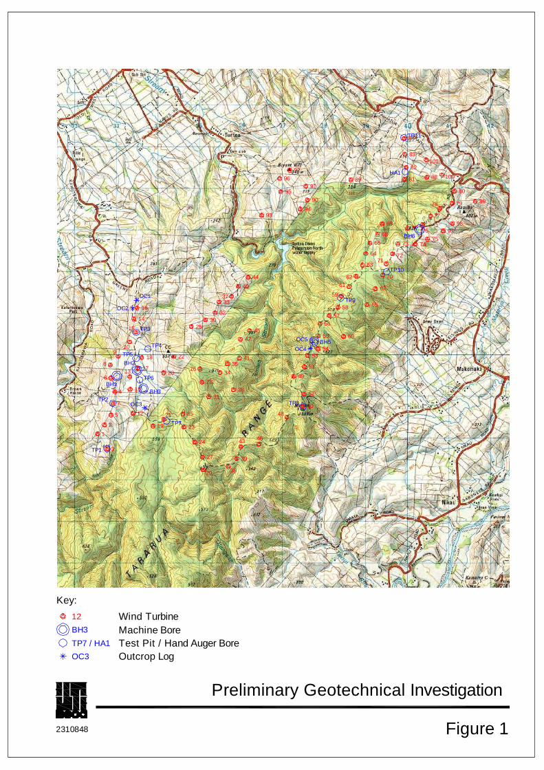
2 Proposed Development Mighty River Power (MRP) in conjunction with Palmerston North City Council (PNCC) propose to construct 90 wind turbines on reserved land in the Turitea district approximately 10km southeast of Palmerston North. The wind turbines are proposed to stand 60m high and have a diameter of 90m. It is understood that each of the turbines will be rated at 3MW and this site will have up to 240 MW capacity. The proposed layout of the site is presented in Figure 1, Appendix A.

Turitea Wind Farm Preliminary Geotechnical Report
2310848 Beca Page 3 I1:57084-JZC67R01.DOC Rev B 6 July 2006
3 Site Description The proposed Turitea wind farm lies within the northwest-southeast aligned Tararua Ranges, east of Palmerston North. The Tararua Ranges form a segment of the North Island axial ranges, which extend from Wellington in the south to East Cape in the North. The geomorphology of the ranges consists of steep sided hills along the eastern and western boundaries, with overall slopes up to 45 degrees and steeper in localised areas. Streams largely drain to the east and west of the axial ranges, which rise up to 571 m in elevation.
The site extends from South Range Road in the north to the John Love property in the south (see Figure 1). The turbines are proposed to be located largely on the western side of the range, which is exposed to the prevailing southwesterly winds. Much of the site is located in the PNCC water supply reserve.

Turitea Wind Farm Preliminary Geotechnical Report
2310848 Beca Page 4 I1:57084-JZC67R01.DOC Rev B 6 July 2006
4 Geology
4.1 Regional Geological Setting The Tararua Ranges are formed of northwest-tilted blocks of indurated sandstone (greywacke) and siltstone, bounded to the southeast by the Wellington fault. The southwestern flank of the Tararua ranges rises steeply from the Northern Ohariu Fault at the base of the range (Figure 2).
The top and western slopes of the ranges are capped by a smooth surface representing an ancient erosion surface upon which early Quaternary alluvial (younger) and terrestrial deposits are preserved (Lee & Begg, 2002). These Quaternary sediments are considered to be deposited from a historical Manawatu River, when elevations of the ranges were considerably lower. A large uplifted, infilled, basin occurs in the southwest corner of the site, known as Browns Flat. The formation of this basin is inferred to be as a result of tectonic uplift, similar to other uplifted basins occurring south of the site.
4.2 Geological Units The two main units shown on published geological maps (Lee and Begg, 2002) of the Turitea wind farm project area are described below in order of age, oldest to most recent. Soil profiles encountered in the investigation are described in more detail in Section 6.
4.2.1 Esk Head Belt (about 160-100 Million years)
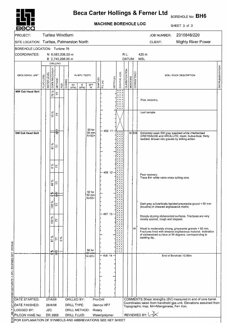
The Esk Head Belt forms the basement rock type of the site and the Tararua Ranges. This unit comprises predominantly extremely weak to moderately strong, highly weathered to moderately weathered, orange to dark grey deformed moderately thinly-bedded sandstone and siltstone sequences within a dark grey sheared argillite matrix (see mapped outcrops, Appendix F). The sheared argillite unit contains boudins (gravel inclusions) of sandstone where the rock has previously undergone extension (pulled apart) and the sandstone layer has stretched and formed a string of ‘sausage’ like gravels where they thicken and thin. The degree of deformation (largely layer-parallel shearing) varies from coherent or transposed beds to broken formation and melange. Small to large lensoid chert, basalt, and limestone blocks are commonly found within highly deformed zones that are regarded as melange.
4.2.2 Quaternary (Alluvial) Deposits (last 1.8 Million years)
The majority of the Quaternary Deposits are observed to occur within the uplifted infilled depression that forms Browns Flat on the eastern side of the wind farm. Here the Quaternary sediments are up to 20 m in thickness overlying Esk Head units. The sediments include a cyclic deposition of alluvial gravels, blue-grey alluvial to lacustrine pumiceous silts and clayey silts, with sparse tephra and organic layers. The cyclic deposition overall appears to grade normally (gradually becomes finer grained upwards). Coarser grained horizons are interpreted to reflect times of cooler climate or storm events.
Elsewhere across the site, Quaternary Deposits are observed to cap hills, and were up to 2.5 m thick. These sediments include pockets of loess, firm-to-stiff orange brown homogeneous silt; alluvial deposits such as medium dense cross-bedded gravels, and interbedded sandy silt and clayey silt deposits.

Turitea Wind Farm Preliminary Geotechnical Report
2310848 Beca Page 5 I1:57084-JZC67R01.DOC Rev B 6 July 2006
5 Site Investigations Preliminary field investigations commenced 3rd April 2006 and were completed 1st May 2006. The locations of the test positions are presented on Figure 1, Appendix A. The field investigation work was directed and logged on site as the work proceeded by an experienced geotechnical engineer or engineering geologist. The scope for this preliminary stage of testing completed is as follows:
5 machine boreholes;
11 Test Pit/Scala Penetrometer tests;
1 Hand Auger hole;
5 Logged outcrops; and
Laboratory testing.
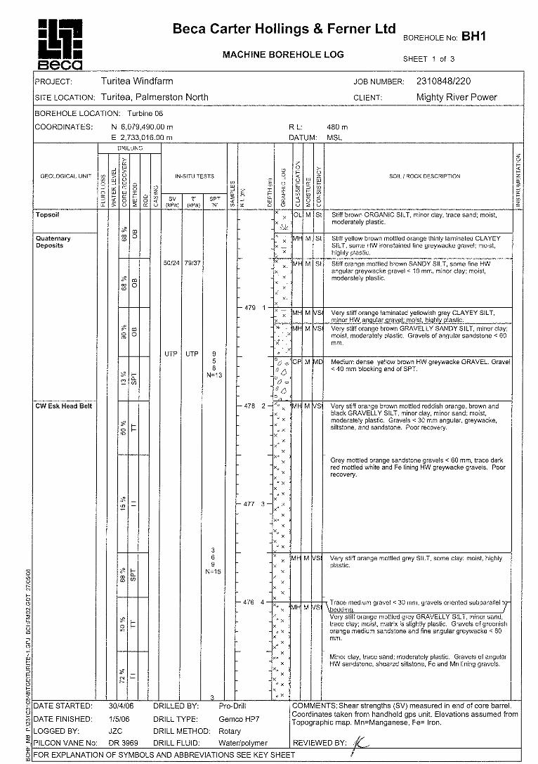
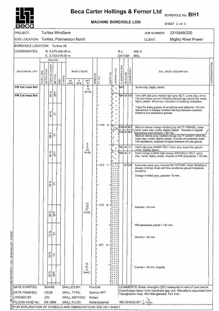
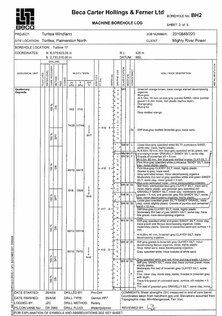
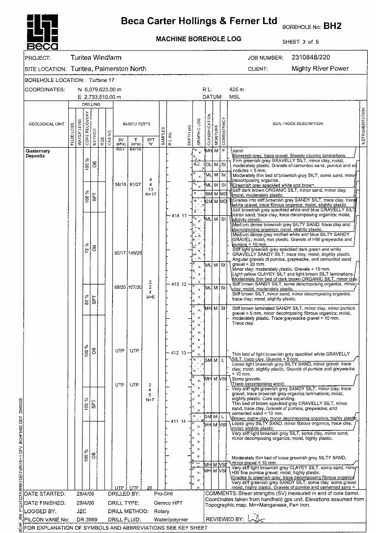
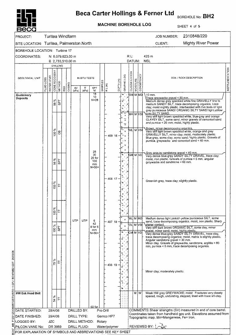
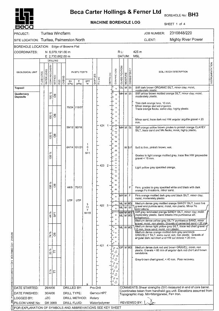
5.1 Machine Boreholes Pro-Drill (Auck) drilled five machine boreholes using rotary techniques with HQ open barrel and triple tube equipment. Standard Penetration Tests were undertaken at 1.5m centres. Six boreholes were initially proposed, however, one borehole was not undertaken due to poor access track conditions during inclement weather. Borehole logs are presented in Appendix B and core photographs are shown in Appendix C.
Soil and rock descriptions used in the borehole logs follow the New Zealand Geotechnical Society Guidelines (NZGS, 2005).
Pilcon Shear vane tests were taken at the end of the core barrel in cohesive soils where appropriate. The results are reported on the log sheets both as ‘field’ readings and ‘corrected’ shear strengths in accordance with NZGS 2001 guidelines.
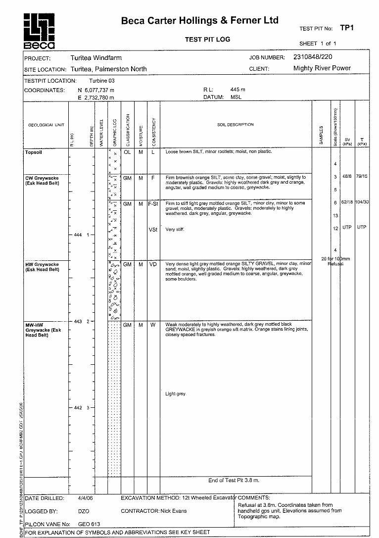
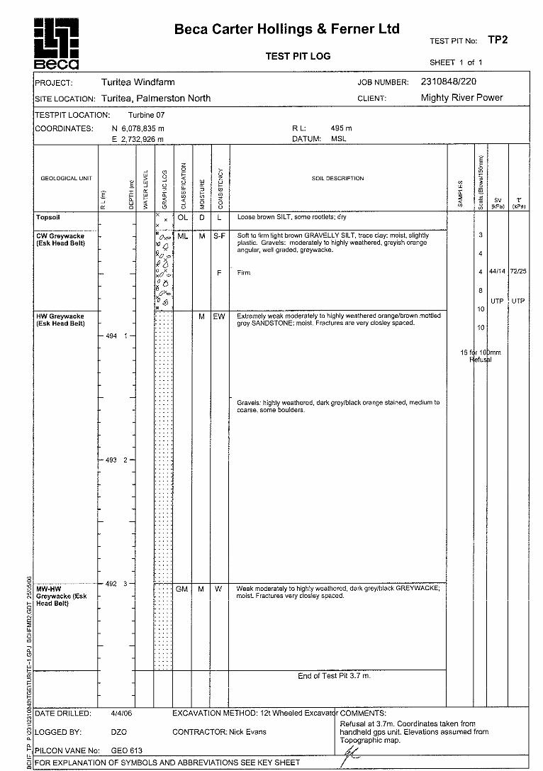
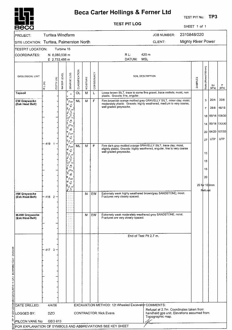
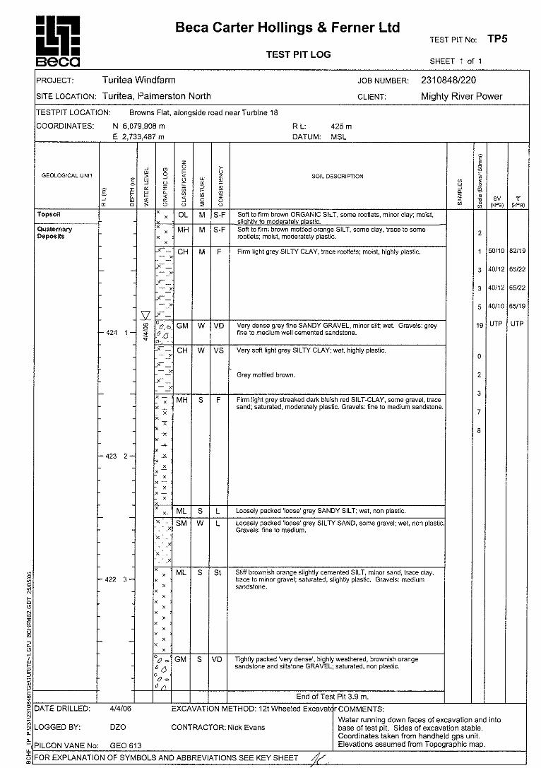
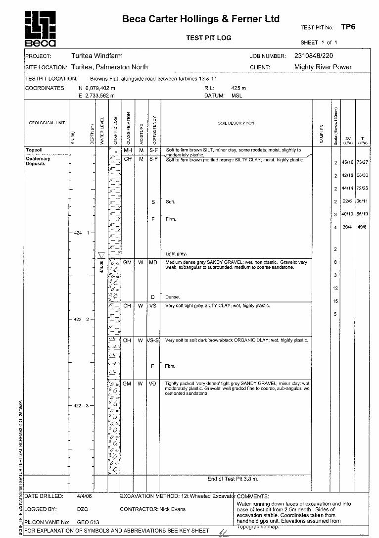
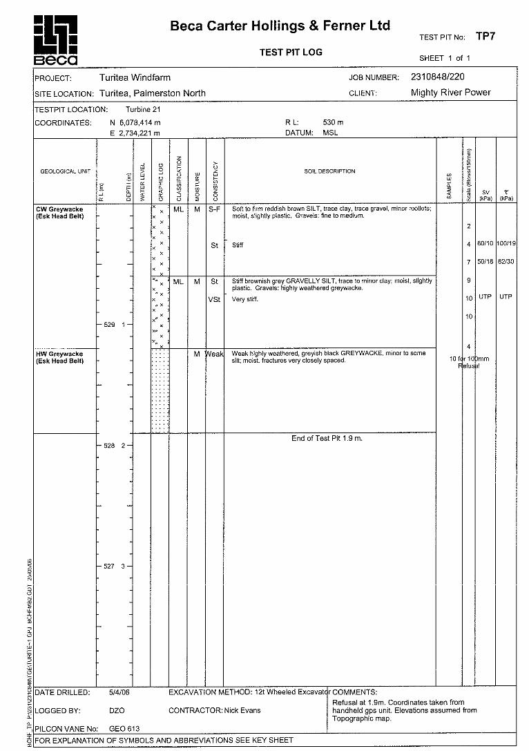
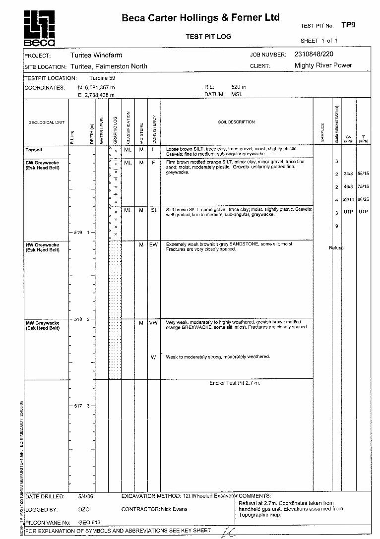
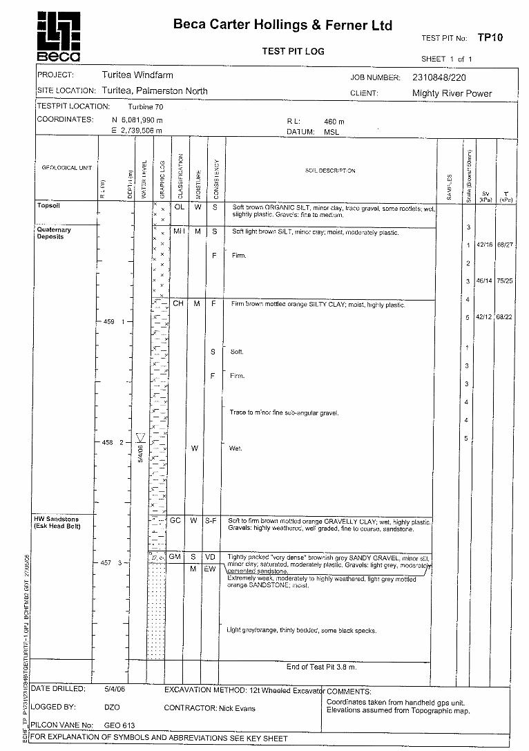
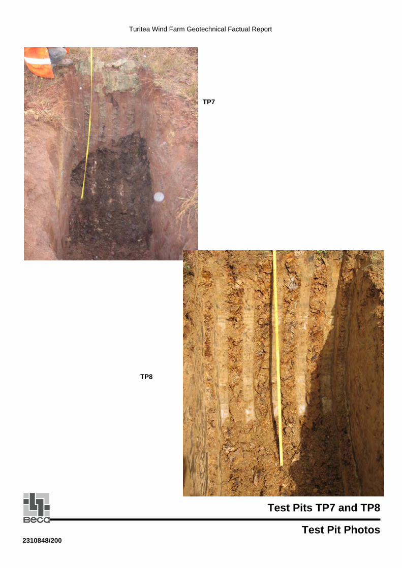
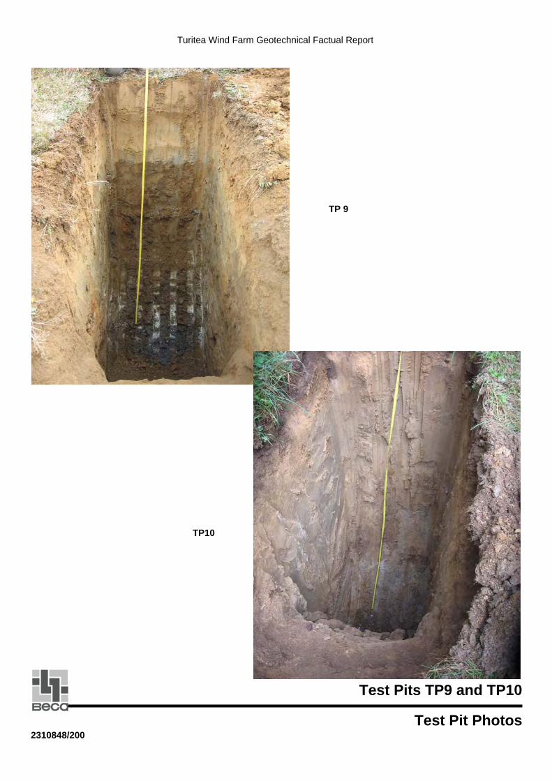
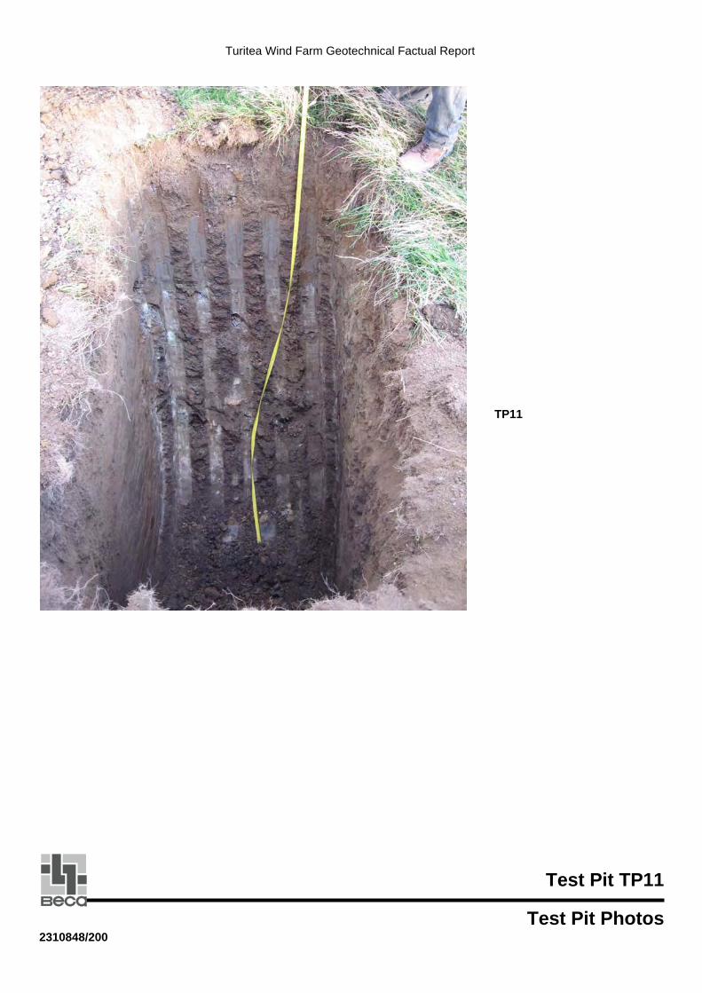
5.2 Test Pits Eleven test pits were undertaken using a 12-tonne excavator from Nick Evans Contractors. Test pit logs are presented in Appendix D. In situ Pilcon Shear vane tests were undertaken where appropriate. Scala penetrometer tests were undertaken from the ground surface and through the base of the pits. Test pit photographs are presented in Appendix E.
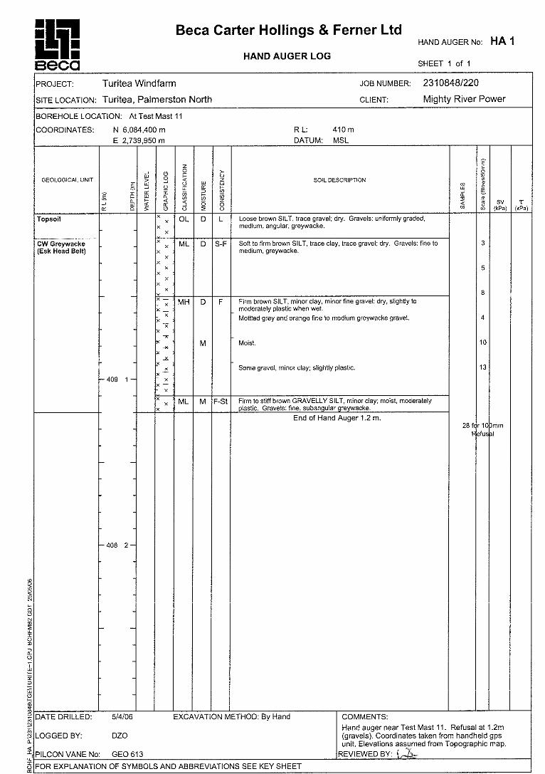
5.3 Hand-Auger Hole A single hand-auger was drilled near the test mast at the northern end of the site, as the excavator could not gain access to the preferred location to undertake a test pit. The hand-auger log is presented in Appendix D. In situ Pilcon shear vanes were undertaken within appropriate materials as the hole progressed. A Scala penetrometer test was carried out at the surface and at the base of the hole.
5.4 Outcrop Mapping Five outcrops of rock were mapped during the course of the field investigations. Photographs of the outcrops and their descriptions are presented in Appendix F. The

Turitea Wind Farm Preliminary Geotechnical Report
2310848 Beca Page 6 I1:57084-JZC67R01.DOC Rev B 6 July 2006
outcrops were mapped to assist in understanding the different rock units present and the geological environment of the site.
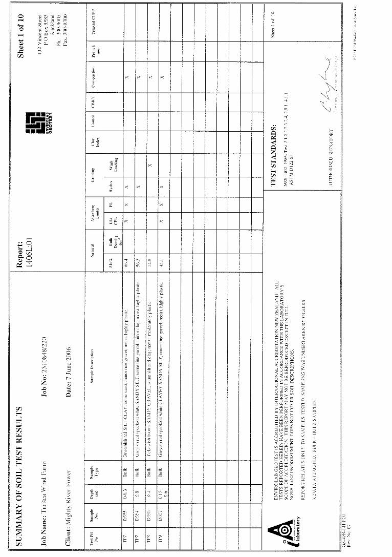
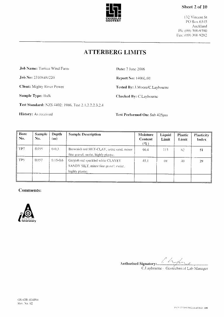
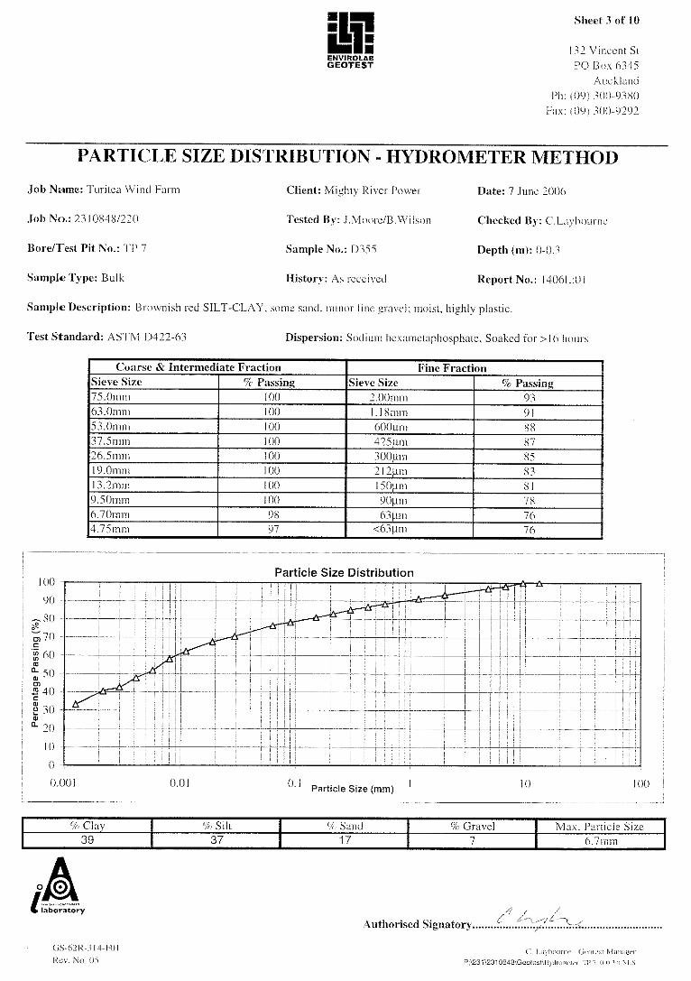
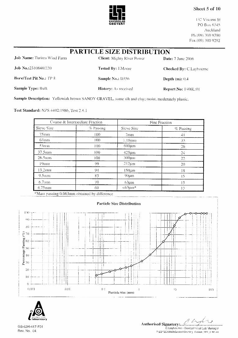
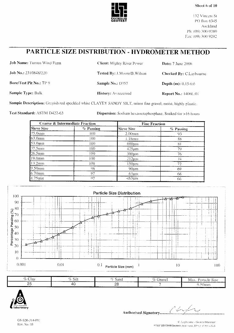
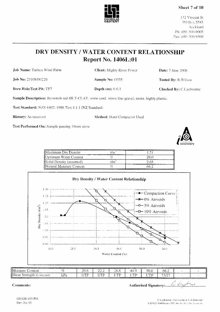
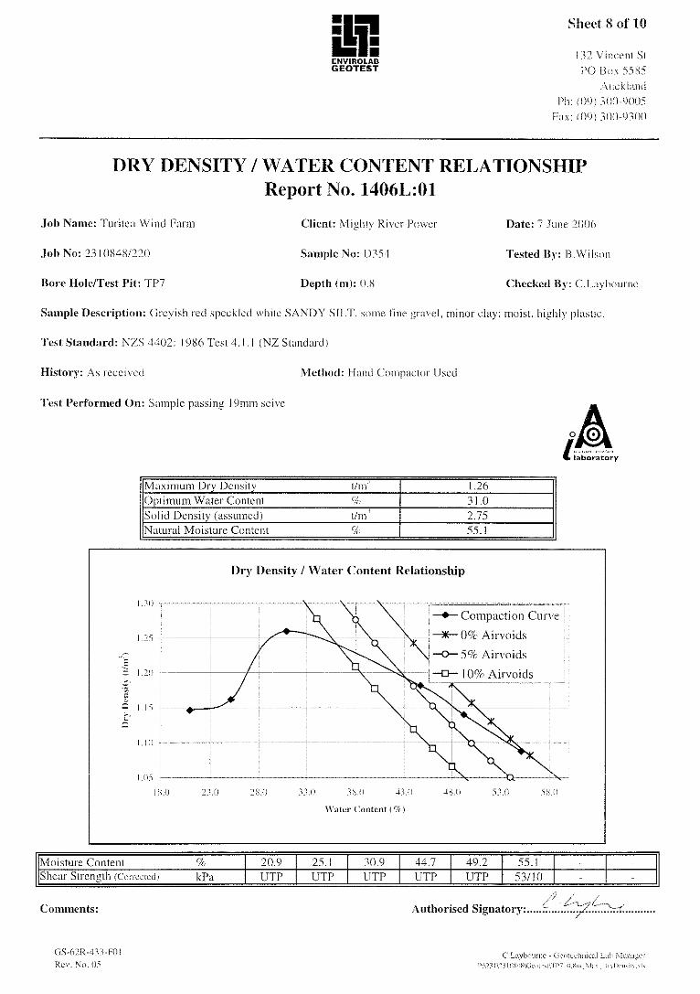
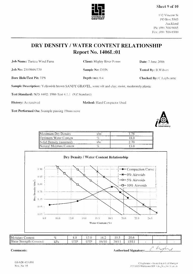
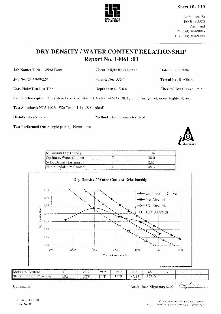
5.5 Laboratory Testing The following lab testing has been scheduled on bulk samples recovered from shallow depths within the test pits. The results are presented in Appendix G.
Table 1: Laboratory Testing Schedule
Test Number
Natural Moisture Content (NMC) 4 Atterberg Limits 2 Wash Grading 1 Hydrometer Grading 3 Standard Compaction 4

Turitea Wind Farm Preliminary Geotechnical Report
2310848 Beca Page 7 I1:57084-JZC67R01.DOC Rev B 6 July 2006
6 Soil Profiles
6.1 Generalised Soil Profile Based on the preliminary investigations, two generalised soil profiles were inferred. Table 2 provides a summary of the soils encountered in Browns Flat, and Table 3 comprises a summary of the soils observed to occur elsewhere over the site.
Table 2: Soil Profile within Browns Flat
Unit Description Depth to top of layer (m)
Thickness(m)
Field Shear Strength (kPa)
SPT N blows /300 mm
Scala blows/150 mm
Firm to stiff brown ORGANIC SILT/SILT (Topsoil)
0 0.1-0.3
Firm to stiff light brown SILT/SILTY CLAY 0.1-0.3 0.4-2.75 22-UTP typ 44
1 2-5 typ 3
Loose to dense grey fine SANDY GRAVEL/SILTY GRAVEL
0.6-1.3 0.2-1 UTP 8 3-19 typ 12
Firm to stiff pink/green/grey SILT/SILTY CLAY
0.9-1.95 0.4-2.1 44 0 0-9 typ 5
Very soft to firm dark brown ORGANIC CLAY 2.2 0-0.5 Loose to medium dense SANDY SILT/SILTY SAND
2.4-2.9 0-0.5 UTP 18
Stiff orange SILT 2.9-3.15 0.35-0.7 Very dense grey GRAVELLY SILT/GRAVEL 2.6-3.6 0.9-2.0 50+ Soft to stiff blue-grey SILT-CLAY 3.7 0-2.7 14-74
typ18 0-7
Firm blue-grey CLAYEY SILT interbedded with SANDY SILT/ GRAVELLY SANDY SILT/SILTY SAND
6.35 2.4 40-67 9
Stiff grey SANDY SILT interbedded with CLAYEY SILT/GRAVELLY SILT/SILTY SAND
8.25 7 40-UTP typ 68
6-17 typ 6
Medium dense grey fine GRAVELLY SANDY SILT interbedded with SAND/ORGANIC SILTY SAND/CLAYEY SILT
15 1.4 28
Qua
tern
ary
Dep
osits
Very dense blue-grey SANDY SILTY GRAVEL interbedded with SILT/ORGANIC SILT
19.6 2 50+
Hard yellow SANDY SILT 5.6 0-0.9 Dense yellow SANDY SILT 6.5 0-6 33-50+
typ 40
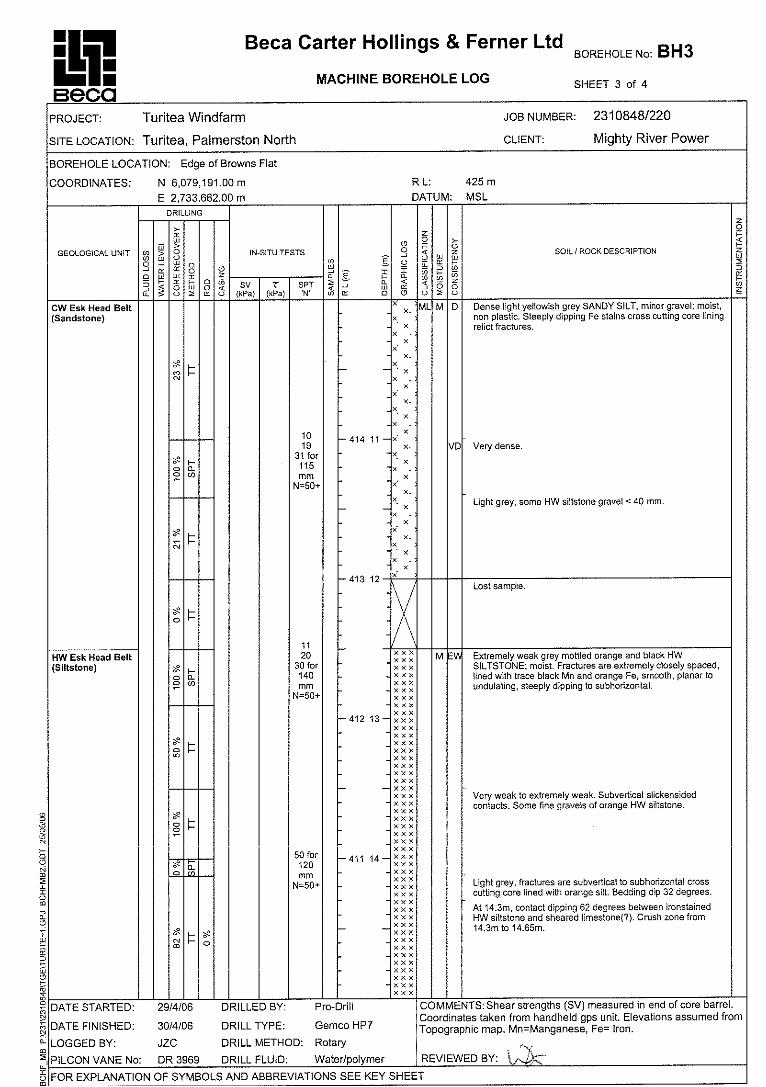
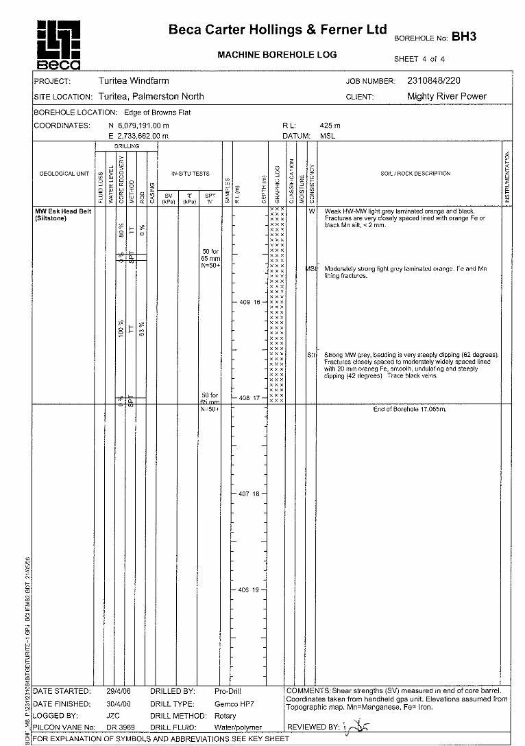
Weak to moderately strong HW GREYWACKE/SANDSTONE
19.6 2 50+
Esk
Hea
d Be
lt
Extremely weak dark grey sheared SILTSTONE 21.6 3m+ 50+
Table 2 is based on investigations BH2, BH3, and TP 4-TP6. Coloured text refers to discontinuous lensing units. The groundwater table within Browns Flat was observed to

Turitea Wind Farm Preliminary Geotechnical Report
2310848 Beca Page 8 I1:57084-JZC67R01.DOC Rev B 6 July 2006
occur 1m below the ground surface within BH2 and was perched above (6.5 m depth) the completely weathered rock units of the Esk Head belt in BH3, near the edge of Browns Flat.
In general, the profile at Browns Flat is characterised by varying depths of interbedded silts, sands and gravels of varying strength, overlying greywacke and associated rock of the Esk Head Belt.
Table 3: General Soil Profile
Unit Description Depth to top of layer
Thickness (m)
Field Shear Strength
SPT N blows /300 mm
Scala blows/150 mm
Loose brown SILT
0 0.15-0.3 3-4 typ 3
Tops
oil
Stiff brown ORGANIC SILT
0 0.1-0.25 3
Soft to stiff yellow brownish orange laminated CLAYEY SILT/SILT
0.2 0-2.5 42-95 1-5 typ 3
Stiff orange brown SANDY SILT/laminated CLAYEY SILT
0.5 0-0.65 50
Qua
tern
ary
Dep
osits
Very stiff orange brown GRAVELLY SANDY SILT/SILTY SAND
1.2-1.5 0-0.8 UTP 13
Firm to stiff brown/reddish brown SILT/CLAYEY SILT
0-0.5 0.6-1.8 42-UTP typ 50
11 1-20 typ 4
Medium dense SILTY SAND 0.75-1.25 0.1 51 11 Stiff to very stiff orange CLAYEY SILT/SILT
1.0-1.85 0.15
Firm to very stiff brown GRAVELLY SILT/GRAVELLY CLAY
0-2.4 0.2-3.5 20-UTP typ 65
13 3-27 typ 10
Medium dense to very dense SILT/SANDY SILT
2 0-1.25
Very stiff orange SILT/GRAVELLY SILT
3.5 0-1.7 15-18
Dense to very dense SILTY GRAVEL/SANDY GRAVEL
0-2.6 0.4-2.2 10-28+ typ 20+l
Esk
Hea
d Be
lt
Extremely weak to moderately strong HW-MW GREYACKE/SILTSTONE
0.2-5.2 11+ 26-50+ typ 50+
Table 3 comprises data based on investigations BH1, BH5, BH6, HA1, TP1-TP3, and TP7-TP11. Coloured text refers to discontinuous lensing layers. BH1, BH6, and TP10 are inferred to have Quaternary Deposits capping the highly weathered Esk Head Belt profile.
Groundwater was observed to occur within the rock units of the Esk Head Belt varying from 0.6m below the ground surface in BH5 and 3.5m below the ground surface in BH6.

Turitea Wind Farm Preliminary Geotechnical Report
2310848 Beca Page 9 I1:57084-JZC67R01.DOC Rev B 6 July 2006
The “typical” soil profile elsewhere on the site (ie beyond Browns Flat) is characterised by a relatively thin surface layer of firm to very stiff gravely silt or gravely clay that has developed from weathering of the underlying rock. These gravely soils are typically medium dense. They are, in places, overlain by firm to stiff silt or clayey silt. The initial laboratory test results indicate that these completely weathered greywacke or siltstone derived materials are highly plastic.
Turitea Wind Farm Preliminary Geotechnical Report
2310848 Beca Page 10 I1:57084-JZC67R01.DOC Rev B 6 July 2006
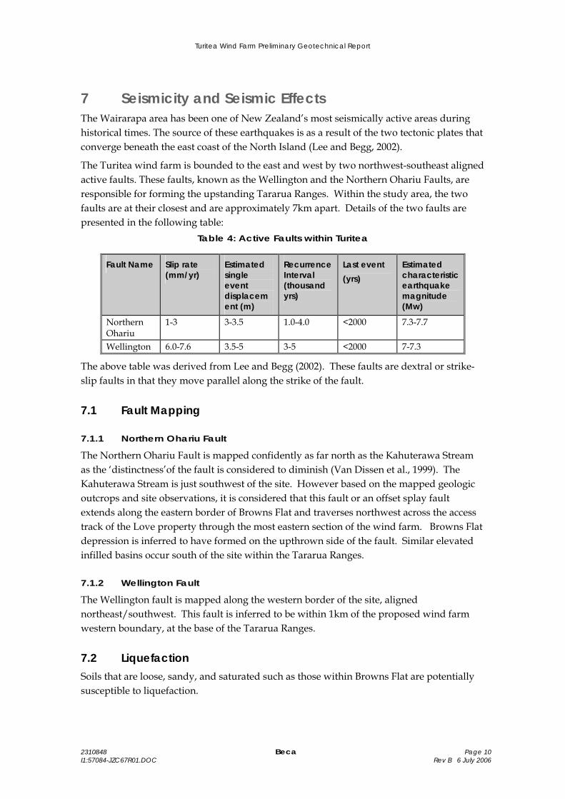
7 Seismicity and Seismic Effects The Wairarapa area has been one of New Zealand’s most seismically active areas during historical times. The source of these earthquakes is as a result of the two tectonic plates that converge beneath the east coast of the North Island (Lee and Begg, 2002).
The Turitea wind farm is bounded to the east and west by two northwest-southeast aligned active faults. These faults, known as the Wellington and the Northern Ohariu Faults, are responsible for forming the upstanding Tararua Ranges. Within the study area, the two faults are at their closest and are approximately 7km apart. Details of the two faults are presented in the following table:
Table 4: Active Faults within Turitea
Fault Name Slip rate (mm/yr)
Estimated single event displacement (m)
Recurrence Interval (thousand yrs)
Last event (yrs)
Estimated characteristic earthquake magnitude (Mw)
Northern Ohariu
1-3 3-3.5 1.0-4.0 <2000 7.3-7.7
Wellington 6.0-7.6 3.5-5 3-5 <2000 7-7.3
The above table was derived from Lee and Begg (2002). These faults are dextral or strike-slip faults in that they move parallel along the strike of the fault.
7.1 Fault Mapping
7.1.1 Northern Ohariu Fault
The Northern Ohariu Fault is mapped confidently as far north as the Kahuterawa Stream as the ‘distinctness’of the fault is considered to diminish (Van Dissen et al., 1999). The Kahuterawa Stream is just southwest of the site. However based on the mapped geologic outcrops and site observations, it is considered that this fault or an offset splay fault extends along the eastern border of Browns Flat and traverses northwest across the access track of the Love property through the most eastern section of the wind farm. Browns Flat depression is inferred to have formed on the upthrown side of the fault. Similar elevated infilled basins occur south of the site within the Tararua Ranges.
7.1.2 Wellington Fault
The Wellington fault is mapped along the western border of the site, aligned northeast/southwest. This fault is inferred to be within 1km of the proposed wind farm western boundary, at the base of the Tararua Ranges.
7.2 Liquefaction Soils that are loose, sandy, and saturated such as those within Browns Flat are potentially susceptible to liquefaction.

Turitea Wind Farm Preliminary Geotechnical Report
2310848 Beca Page 11 I1:57084-JZC67R01.DOC Rev B 6 July 2006
8 Preliminary Geotechnical Recommendations
8.1 Introduction The investigations carried out to date have been designed to broadly characterise the likely ground conditions across the Turitea wind farm site and thus form the basis of preliminary engineering work for the project. Specific preliminary recommendations are given in the following sections.
The site is underlain by two distinct geotechnical units, the Esk Head Belt “greywacke” and the Browns Flat alluvium. Where appropriate, we have provided separate recommendations for each unit.
8.2 Earthworks Fill materials are likely to be sourced from the greywacke profile, rather from within Browns Flat.
At shallow depth, the natural moisture content of the surface layer of firm to very stiff gravely silt or gravely clay is just above the plastic limit. The clay and silt dominated materials are significantly wet of optimum moisture content for compaction, while the sandy gravel sample was found on testing to be dry of optimum. Mixing will occur during excavation, transporting and spreading, and is likely to result in a material that is closer to optimum moisture content. Some additional sorting, mixing and moisture conditioning (wetting or drying) will likely be required in places, and will need to be controlled during construction.
Rock excavation is likely to be achieved using a range of techniques, from hard digging (eg 30-40t excavator) to hard ripping (eg D8 with a single tine). Localised areas (eg larger lenses of chert or basalt, and the strong to very strong rock at the top of the hill immediately north of Browns Flat) may require hydraulic breaking or blasting.
Cut batters in soil and rock of 1 (v) on 1 (h) appear suitable for most situations. Temporary cuts for turbine foundations in Browns Flat may need to be flatter, particularly where they extend below ground water level. Steeper batters will likely be achievable in rock, depending on local conditions (defect orientation and spacing) in the rock mass. A reasonable approach for short term cut slopes (eg site access roads) may be to cut the batters steep (eg 2 to 4 (v) on 1 (h)) and clean up any dropouts that occur during the construction phase. Subsequent failures may, however, block side drains and result in localised increases in sediment runoff, requiring ongoing maintenance. Steepening of cut slopes in rock should be assessed later in the investigation and design process, if of value.
Fill batters should initially be set at 1 (v) on 2 (h). The final selection of batter slope will depend on fill height and foundation conditions, and will need to be assessed in the course of investigation and design.
The appropriateness of all batter slopes will need to be confirmed on site as construction work proceeds.
Guidance on the likely performance of trench excavations for cables can be obtained from the test pit logs and photos in Appendices D and E. The performance of a long trench that
Turitea Wind Farm Preliminary Geotechnical Report
2310848 Beca Page 12 I1:57084-JZC67R01.DOC Rev B 6 July 2006
may be open for hours to days will not, however, be as good as that of a short (in length) pit that is left open for only a brief period of time.
The settlement of any significant fills across Browns Flat may be large, and continue for a significant period of time. This will need to be specifically assessed.
8.3 Roading Pavements on completely weathered greywacke can be designed on the basis of a Scala penetrometer blowcount of 4 blows or more per 150mm (subgrade CBR = 5%). Pavements on alluvium (eg Browns Flat) should be designed on the basis of a Scala penetrometer blowcount of 2 blows per 150mm (subgrade CBR = 2-3%). Allowance should be made for testing and confirmation of subgrade conditions, and local undercutting of weaker materials encountered during construction.
Engineered fills constructed from excavated and compacted rock are likely to achieve a subgrade CBR of 10% or better.
Pavements on cut rock can be designed on the basis of a Scala penetrometer blowcount of 15 to 20 blows per 150mm (subgrade CBR = 20%). In these conditions, the pavements are predominantly required just to provide an even running surface.
Setback distances for cranes from the crest of cuts and fills will require specific assessment. Preliminary layouts should be based on a setback defined by a line drawn up from the base of cuts at 1 (v) on 2 (h). A 3m setback from the crest of fills is recommended.
8.4 Foundations Spread foundations are likely to prove suitable for the turbines that are underlain by greywacke at relatively shallow depth. Specific analysis may demonstrate that sites with a moderate depth of weathering (eg BH1) will also prove suitable for spread foundations. In areas underlain by alluvium (eg Browns Flat), piled foundations taken to the underlying rock are likely to be required.
Bored piles are likely to be most suited to the site conditions, as they will be able to penetrate the underlying rock to the required depth. They can provisionally be sized on the basis of an ultimate socket friction in rock of 350kPa, and an ultimate end bearing pressure of 5MPa. A strength reduction factor of 0.5 should be applied to these values for comparison with code factored loads. A factor of safety of 3 should be used when comparing capacities derived using these values with unfactored loads.
Further investigation and analysis is required to confirm and refine these values. Site confirmation inspection and testing will be required at each turbine location.
8.5 Aggregate Sources The underlying greywacke rock at the site is highly variable, and is unlikely to provide a suitable source of basecourse or concrete aggregate. Off site commercial sources will likely need to be utilised for concrete aggregate and for the running surface of permanent unsealed roads. Selected material won from cuts may be able to be screened and used for surfacing site roads. This is the approach that appears to be adopted for the current access

Turitea Wind Farm Preliminary Geotechnical Report
2310848 Beca Page 13 I1:57084-JZC67R01.DOC Rev B 6 July 2006
roads through the site. The increased traffic volumes and vehicle loads over current usage will result in greatly increased maintenance requirements where these relatively low quality site materials are used.

Turitea Wind Farm Preliminary Geotechnical Report
2310848 Beca Page 14 I1:57084-JZC67R01.DOC Rev B 6 July 2006
9 Further Investigations The current study presents an initial appraisal of likely conditions across the Turitea wind farm site. Access at this relatively early stage in the project has been limited, to the extent that a fully representative sample of site conditions may not have been obtained. Further subsurface investigation and analysis is necessary, and is planned to be undertaken once the project is confirmed.
In addition to the currently planned investigation, we recommend that the observed and inferred fault trace is more closely assessed by analysis of stereopairs of aerial photographs of the site. This appraisal will allow the trace of the potential fault to be better located and an assessment to be made of how it may potentially impact the proposed site works. Trenching across the fault trace may also be required.

Turitea Wind Farm Preliminary Geotechnical Report
2310848 Beca Page 15 I1:57084-JZC67R01.DOC Rev B 6 July 2006
10 References Lee, J.M., and Begg, J.G. 2002: Geology of the Wairarapa Area. Institute of Geological and Nuclear Sciences, 1:250,000, Geological Map 11.
Van Dissen, R.J., Heron, D.W., Palmer, A. 1999: Ohariu and Northern Ohariu faults; field guide to Late Quaternary active faulting. P 29-69. In: Palmer, A (ed) Geological Society of New Zealand Inc 1999 Annual Conference, 29 November - 1 December, Massey University, Palmerston North: field trip guides. Wellington, NZ: Geological Society of New Zealand. Geological Society of New Zealand Miscellaneous Publication 107B.

D R A F T
Appendix A
Figures
1 2
3
4
5
6
7
8
9 10
11
12
13
14
15
16
17
18
19
20
21
22
23
24
25
26
27
28
29
30
31
32
33
34 35
36
37
38
39
40
41
42
43
44
45
46
48
49
50
51
52
53 54
55
56 57
58
59
60
61 62
63
64
65
66
67
68
69
70
71 72
73 74 75
76
77
78 79
80
81
82
83
84
85
87 97 98
99
101
90
91
92
89 88
93 94
95
96 100
BH6
BH5
BH3
BH2
BH1
HA1
TP1
TP10
TP11
TP2
TP3
TP4TP5
TP6
TP7
TP8
TP9OC1
OC2
OC3
OC4
OC5
2310848 Figure 1
Preliminary Geotechnical Investigation
Key:12BH3TP7 / HA1OC3
Wind TurbineMachine BoreTest Pit / Hand Auger BoreOutcrop Log

Turitea Geology
Figure 22310848
10km
Legend:RelevantGeological UnitseQa - Quaternary DepositsTe - Esk Head Belt
Faults Active Faults
Inferred Faults
Tararua Ranges
Approximate extent of Wind Farm
Browns Flat
Te
Map derived from Lee and Begg ( 2002). Inferred faults based on site observations.


A Beca Carter Hollings & Ferner Ltd
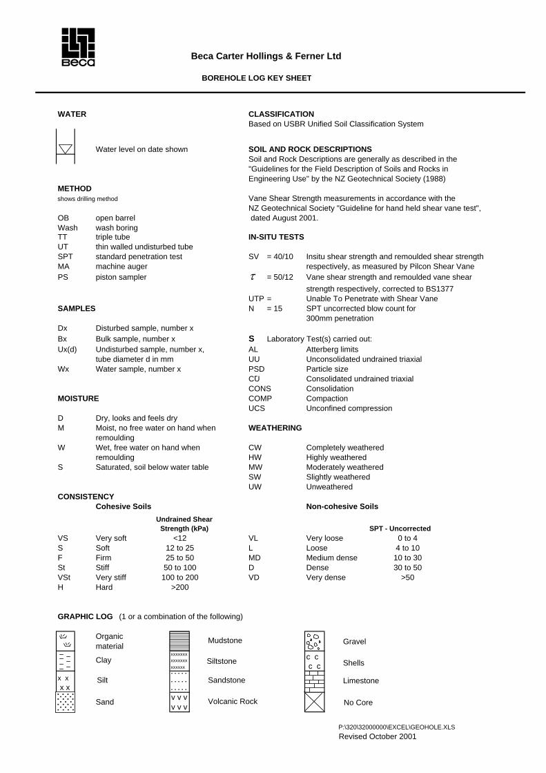
BOREHOLE LOG KEY SHEET
WATER CLASSIFICATIONBased on USBR Unified Soil Classification System
Water level on date shown SOIL AND ROCK DESCRIPTIONSSoil and Rock Descriptions are generally as described in the"Guidelines for the Field Description of Soils and Rocks inEngineering Use" by the NZ Geotechnical Society (1988)
METHODshows drilling method Vane Shear Strength measurements in accordance with the
NZ Geotechnical Society "Guideline for hand held shear vane test",OB open barrel dated August 2001.Wash wash boringTT triple tube IN-SITU TESTSUT thin walled undisturbed tubeSPT standard penetration test SV = 40/10 Insitu shear strength and remoulded shear strengthMA machine auger respectively, as measured by Pilcon Shear VanePS piston sampler τ = 50/12 Vane shear strength and remoulded vane shear
strength respectively, corrected to BS1377 UTP = Unable To Penetrate with Shear Vane
SAMPLES N = 15 SPT uncorrected blow count for300mm penetration
Dx Disturbed sample, number xBx Bulk sample, number x S Laboratory Test(s) carried out:Ux(d) Undisturbed sample, number x, AL Atterberg limits
tube diameter d in mm UU Unconsolidated undrained triaxialWx Water sample, number x PSD Particle size
CU Consolidated undrained triaxialCONS Consolidation
MOISTURE COMP CompactionUCS Unconfined compression
D Dry, looks and feels dryM Moist, no free water on hand when WEATHERING
remouldingW Wet, free water on hand when CW Completely weathered
remoulding HW Highly weatheredS Saturated, soil below water table MW Moderately weathered
SW Slightly weatheredUW Unweathered
CONSISTENCYCohesive Soils Non-cohesive Soils
SPT - UncorrectedVS Very soft <12 VL Very loose 0 to 4S Soft 12 to 25 L Loose 4 to 10F Firm 25 to 50 MD Medium dense 10 to 30St Stiff 50 to 100 D Dense 30 to 50VSt Very stiff 100 to 200 VD Very dense >50H Hard >200
GRAPHIC LOG (1 or a combination of the following)
Organicmaterial
xxxxxxxxxxxxxx c cxxxxxx c c
x x. . . . . . . . . .
x x . . . . .v v vv v v
P:\320\32000000\EXCEL\GEOHOLE.XLSRevised October 2001
Undrained Shear Strength (kPa)
Clay
Silt
Sand
GravelMudstone
Siltstone
Sandstone
Volcanic Rock No Core
Limestone
Shells


Turitea Wind Farm Preliminary Geotechnical Investigation
BOX: 1 DEPTH: 0 to 5.0m
BOX: 2 DEPTH: 5.0 to 10.0m
BH1 0 to 10m
2310848/200 Borehole Photos

Turitea Wind Farm Preliminary Geotechnical Investigation
BOX: 3 DEPTH: 10.0 to 14.5m
BH1 10 to 14.5m
2310848/200 Borehole Photos
Turitea Wind Farm Preliminary Geotechnical Investigation
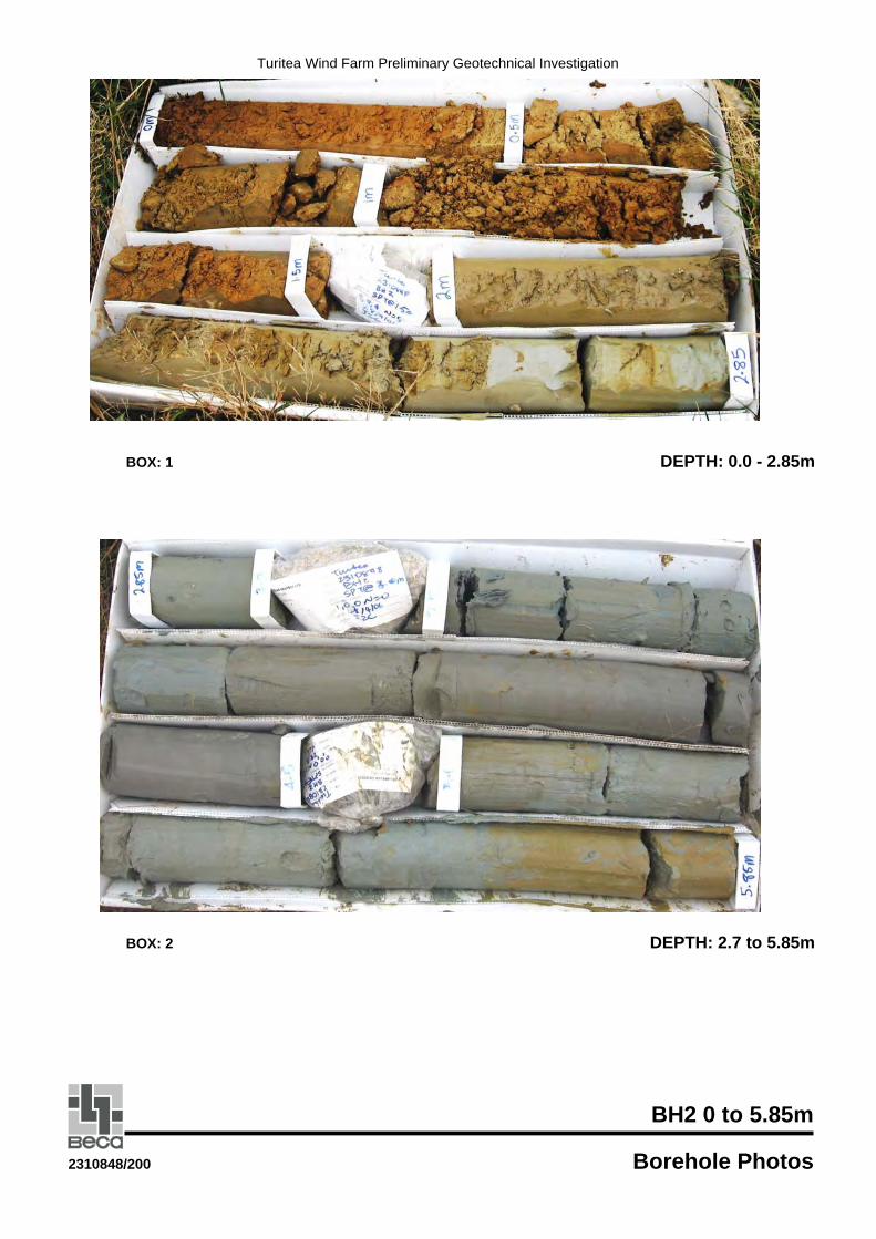
BOX: 1 DEPTH: 0.0 - 2.85m
BOX: 2 DEPTH: 2.7 to 5.85m
BH2 0 to 5.85m
2310848/200 Borehole Photos
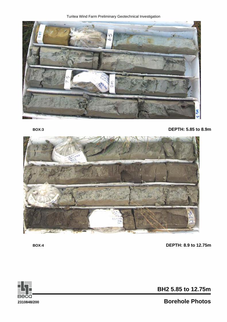
Turitea Wind Farm Preliminary Geotechnical Investigation
BOX:3 DEPTH: 5.85 to 8.9m
BOX:4 DEPTH: 8.9 to 12.75m
BH2 5.85 to 12.75m
2310848/200 Borehole Photos
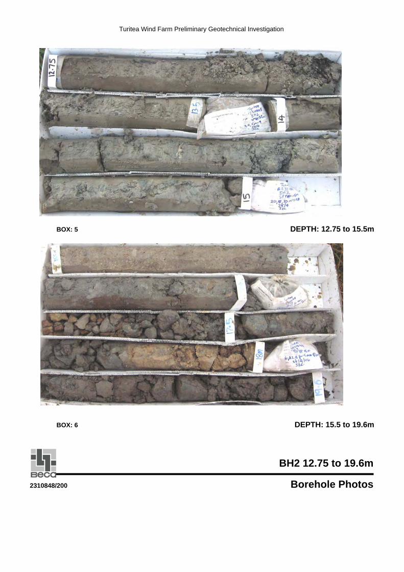
Turitea Wind Farm Preliminary Geotechnical Investigation
BOX: 5 DEPTH: 12.75 to 15.5m
BOX: 6 DEPTH: 15.5 to 19.6m
BH2 12.75 to 19.6m
2310848/200 Borehole Photos
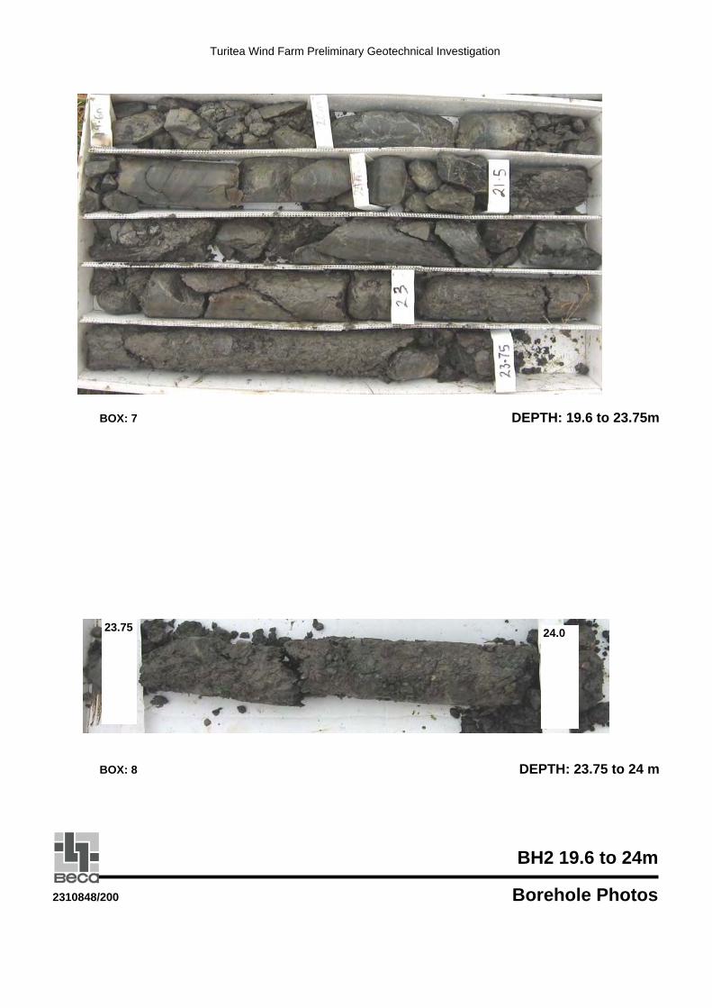
Turitea Wind Farm Preliminary Geotechnical Investigation
BOX: 7 DEPTH: 19.6 to 23.75m
BOX: 8 DEPTH: 23.75 to 24 m
BH2 19.6 to 24m
2310848/200 Borehole Photos
23.75 24.0
Turitea Wind Farm Preliminary Geotechnical Investigation
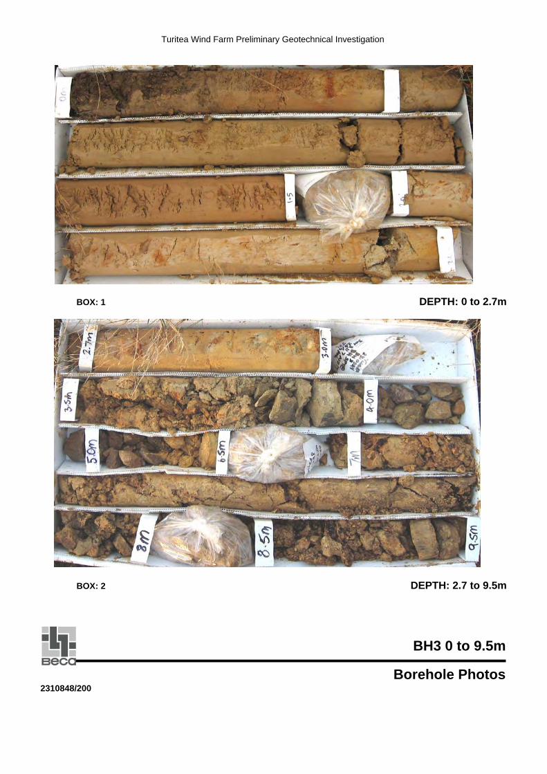
BOX: 1 DEPTH: 0 to 2.7m
BOX: 2 DEPTH: 2.7 to 9.5m
BH3 0 to 9.5m
Borehole Photos2310848/200
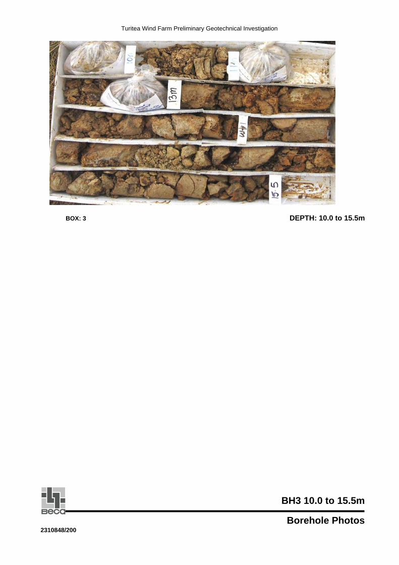
Turitea Wind Farm Preliminary Geotechnical Investigation
BOX: 3 DEPTH: 10.0 to 15.5m
BH3 10.0 to 15.5m
Borehole Photos2310848/200
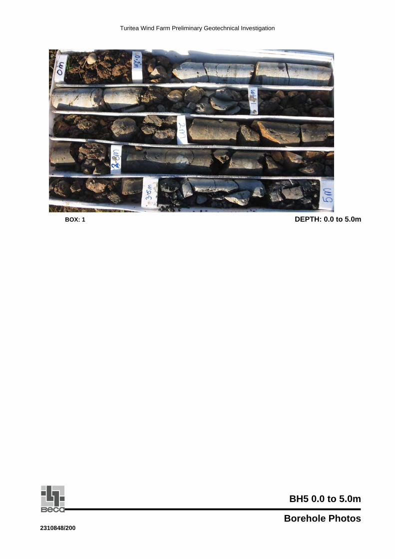
Turitea Wind Farm Preliminary Geotechnical Investigation
BOX: 1 DEPTH: 0.0 to 5.0m
BH5 0.0 to 5.0m
Borehole Photos2310848/200

Turitea Wind Farm Preliminary Geotechnical Investigation
Box: 1 DEPTH: 0.0 to 4.5m
Box: 2 DEPTH: 4.5 to 11m
BH6 0 to 11m
Borehole Photos2310848/200
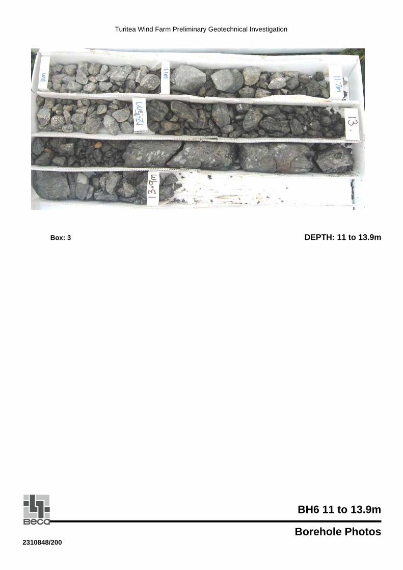
Turitea Wind Farm Preliminary Geotechnical Investigation
Box: 3 DEPTH: 11 to 13.9m
BH6 11 to 13.9m
Borehole Photos2310848/200

A Beca Carter Hollings & Ferner Ltd
BOREHOLE LOG KEY SHEET
WATER CLASSIFICATIONBased on USBR Unified Soil Classification System
Water level on date shown SOIL AND ROCK DESCRIPTIONSSoil and Rock Descriptions are generally as described in the"Guidelines for the Field Description of Soils and Rocks inEngineering Use" by the NZ Geotechnical Society (1988)
METHODshows drilling method Vane Shear Strength measurements in accordance with the
NZ Geotechnical Society "Guideline for hand held shear vane test",OB open barrel dated August 2001.Wash wash boringTT triple tube IN-SITU TESTSUT thin walled undisturbed tubeSPT standard penetration test SV = 40/10 Insitu shear strength and remoulded shear strengthMA machine auger respectively, as measured by Pilcon Shear VanePS piston sampler τ = 50/12 Vane shear strength and remoulded vane shear
strength respectively, corrected to BS1377 UTP = Unable To Penetrate with Shear Vane
SAMPLES N = 15 SPT uncorrected blow count for300mm penetration
Dx Disturbed sample, number xBx Bulk sample, number x S Laboratory Test(s) carried out:Ux(d) Undisturbed sample, number x, AL Atterberg limits
tube diameter d in mm UU Unconsolidated undrained triaxialWx Water sample, number x PSD Particle size
CU Consolidated undrained triaxialCONS Consolidation
MOISTURE COMP CompactionUCS Unconfined compression
D Dry, looks and feels dryM Moist, no free water on hand when WEATHERING
remouldingW Wet, free water on hand when CW Completely weathered
remoulding HW Highly weatheredS Saturated, soil below water table MW Moderately weathered
SW Slightly weatheredUW Unweathered
CONSISTENCYCohesive Soils Non-cohesive Soils
SPT - UncorrectedVS Very soft <12 VL Very loose 0 to 4S Soft 12 to 25 L Loose 4 to 10F Firm 25 to 50 MD Medium dense 10 to 30St Stiff 50 to 100 D Dense 30 to 50VSt Very stiff 100 to 200 VD Very dense >50H Hard >200
GRAPHIC LOG (1 or a combination of the following)
Organicmaterial
xxxxxxxxxxxxxx c cxxxxxx c c
x x. . . . . . . . . .
x x . . . . .v v vv v v
P:\320\32000000\EXCEL\GEOHOLE.XLSRevised October 2001
Undrained Shear Strength (kPa)
Clay
Silt
Sand
GravelMudstone
Siltstone
Sandstone
Volcanic Rock No Core
Limestone
Shells


Turitea Wind Farm Preliminary Geotechnical Investigation
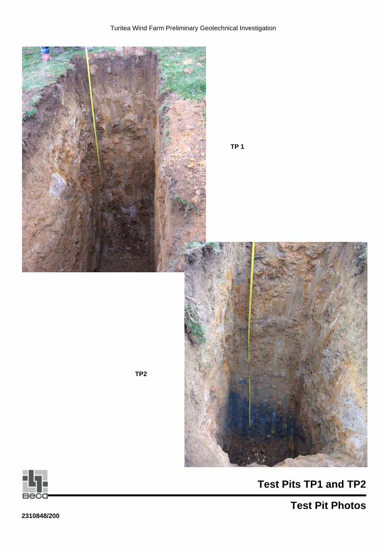
TP 1
TP1
TP2
Test Pits TP1 and TP2
Test Pit Photos2310848/200

Turitea Wind Farm Preliminary Geotechnical Investigation
TP3
TP4
Test Pits TP3 and TP4
Test Pit Photos2310848/200
Turitea Wind Farm Preliminary Geotechnical Investigation
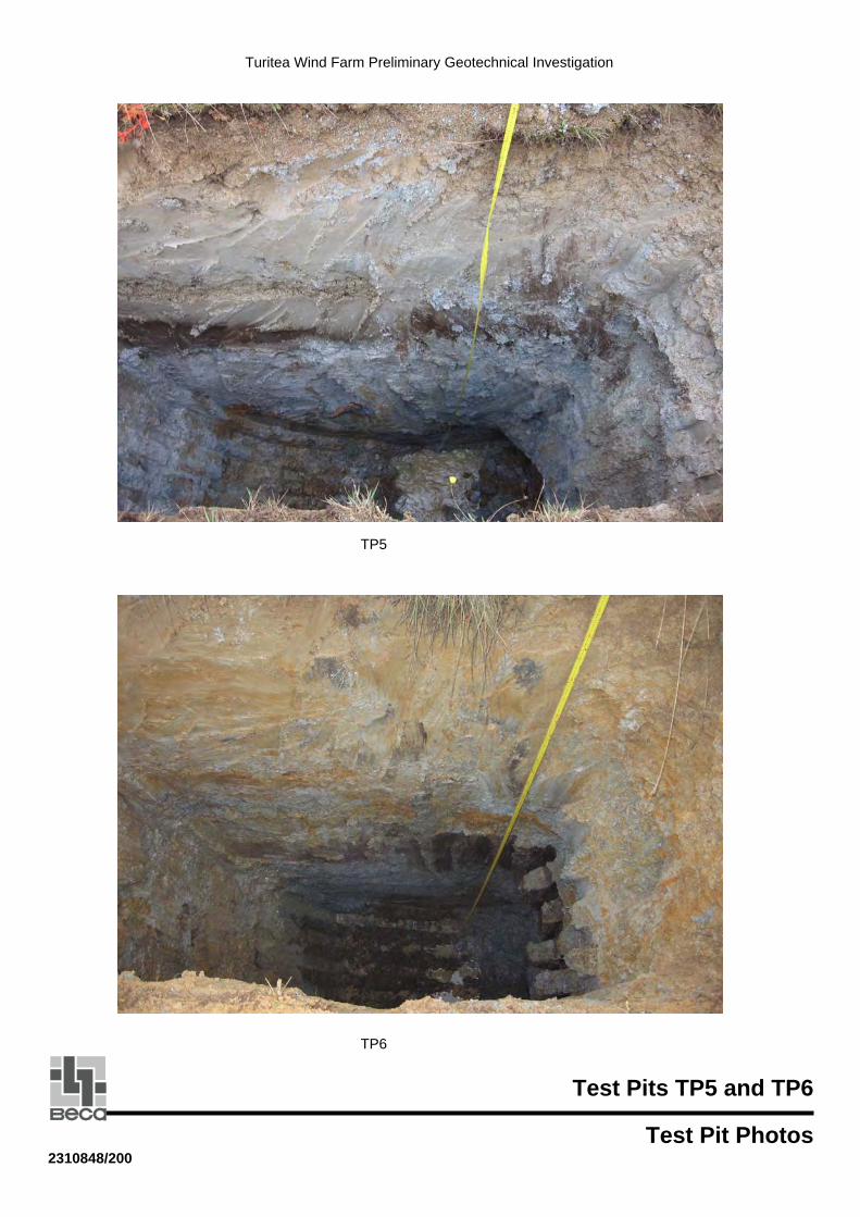
TP5
TP6
Test Pits TP5 and TP6
Test Pit Photos2310848/200
Turitea Wind Farm Geotechnical Factual Report
TP7
TP8
Test Pits TP7 and TP8
Test Pit Photos2310848/200
Turitea Wind Farm Geotechnical Factual Report
TP 9
TP1
TP10
Test Pits TP9 and TP10
Test Pit Photos2310848/200
Turitea Wind Farm Geotechnical Factual Report
TP11TP3
Test Pit TP11
Test Pit Photos2310848/200

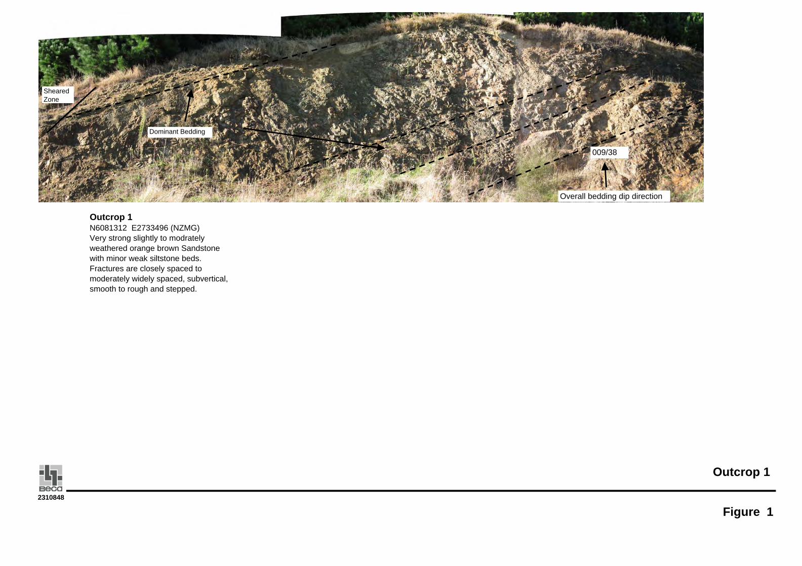
Outcrop 1
Figure 12310848
Outcrop 1N6081312 E2733496 (NZMG)Very strong slightly to modrately weathered orange brown Sandstone with minor weak siltstone beds. Fractures are closely spaced to moderately widely spaced, subvertical, smooth to rough and stepped.
009/38
Overall bedding dip direction
Sheared Zone
Dominant Bedding

Outcrop 2
Figure 22310848
Outcrop 2
N6081126 E2733407 (NZMG)Weak moderately weathered interbedded greenish grey Siltstone and moderately strong to strong grey brown Sandstone. Fractures are closely spaced, subvertical, rough to planar. Historical fault structure at centre of figure material on right hand side abutting against material on left hand side. Delineated by the change in orientation of bedding inclination.
Slope Debris Slope Debris
Sandstone beds up to 310 mm
Siltstone beds up to 180 mm
182/15
348/40
Disturbed fault zone?

Outcrop 3
Figure 32310848
18m
Outcrop 3 East of Browns Flat
N 6078729 E2733694 (NZMG)Weak to moderately strong highly to moderately weathered dark red brown Argillite with variable dips and bedding dip direction. Fractures are very closely to closely spaced, rough, irregular, and lined with dark red silt. Bedding inclination varies from 47 to 63 degrees.
Bedding dip direction
003/58-63058/47-59
Outcrop 4
Figure 42310848
Sheared Zone
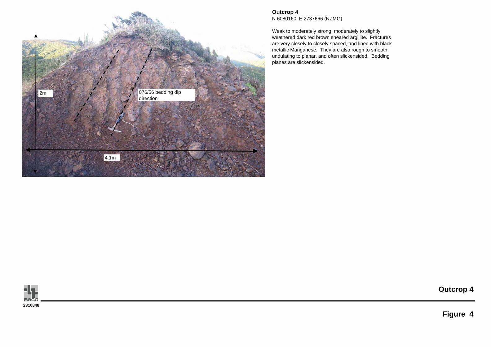
Outcrop 4N 6080160 E 2737666 (NZMG)
Weak to moderately strong, moderately to slightly weathered dark red brown sheared argillite. Fractures are very closely to closely spaced, and lined with black metallic Manganese. They are also rough to smooth, undulating to planar, and often slickensided. Bedding planes are slickensided.
076/56 bedding dip direction
4.1m
2m
Outcrop 5
Figure 52310848
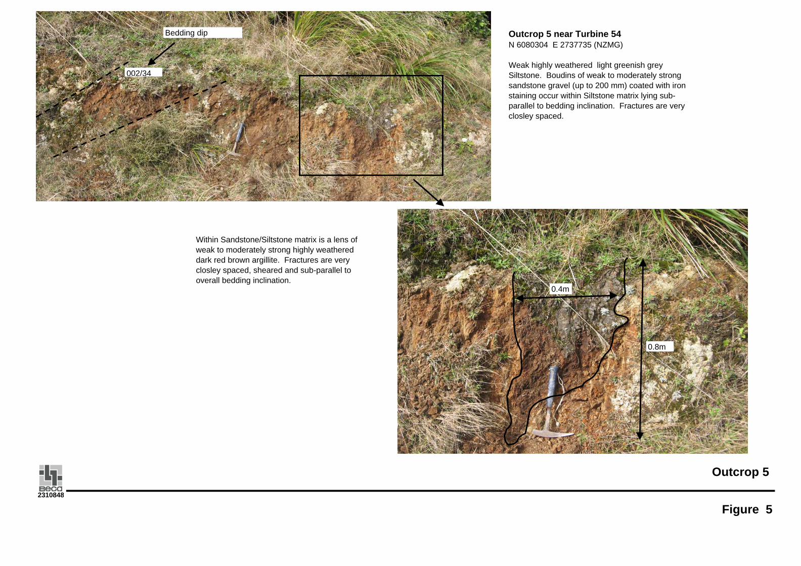
002/34
Bedding dip Outcrop 5 near Turbine 54N 6080304 E 2737735 (NZMG)
Weak highly weathered light greenish grey Siltstone. Boudins of weak to moderately strong sandstone gravel (up to 200 mm) coated with iron staining occur within Siltstone matrix lying sub-parallel to bedding inclination. Fractures are very closley spaced.
0.8m
0.4m
Within Sandstone/Siltstone matrix is a lens of weak to moderately strong highly weathered dark red brown argillite. Fractures are very closley spaced, sheared and sub-parallel to overall bedding inclination.