FLO/STRESS V4.1 Training Course Tutorial - Basic Operation Tutorial - Basic Operation of FLO/STRESS Introduction FLO/STRESS is intended to provide a fast, accurate stress prediction within the product design cycle. It is intended to provide the thermal designer with a greater understanding of the thermomechanical behavior of the proposed design so that fewer problems are encountered during prototyping and accelerated testing, thereby reducing cost and time to market. This tutorial covers the basic operation of the FLO/STRESS module incorporated into FLOTHERM V4.1. The tutorial exercise considers a very simple case, which has already been set up for you. The case is used to show most of the features of FLO/STRESS (and discuss the others) so that you should end up being familiar with the mechanics of how to do a thermomechanical analysis. We also use the case to introduce some finite element terminology, and to highlight some of the modeling issues associated with doing a thermomechanical analysis. Model Description To start we need to run FLOTHERM and load in the base case for the tutorial. The model is a MMIC (Monolithic Microwave Integrated Circuit). This is comprised of a gallium arsenide die, on which are four 1W heat sources, which is soldered to a copper tungsten (Cu10/W90) substrate with gold germanium eutectic solder. Loading the Tutorial Action Result In the Project Manager Select the [Project/New] The [New Project] dialog should be displayed. In the [New Project] dialog select the [FloStress] tab The dialog should now display the available tutorial cases In the [New Project] dialog select the project “GaAs MMIC” [OK] the dialog. Expand the project tree with [View/ Expand All] (or by pressing [F6] on the keyboard) The project consists of a single assembly that contains 3 cuboids representing the die, die attach and the substrate. There are also four identical heat sources on top of the die. 1 of 16
Transcript
FLO/STRESS V4.1 Training Course Tutorial - Basic Operation
Tutorial - Basic Operation of FLO/STRESS Introduction FLO/STRESS is intended to provide a fast, accurate stress prediction within the product design cycle. It is intended to provide the thermal designer with a greater understanding of the thermomechanical behavior of the proposed design so that fewer problems are encountered during prototyping and accelerated testing, thereby reducing cost and time to market. This tutorial covers the basic operation of the FLO/STRESS module incorporated into FLOTHERM V4.1. The tutorial exercise considers a very simple case, which has already been set up for you. The case is used to show most of the features of FLO/STRESS (and discuss the others) so that you should end up being familiar with the mechanics of how to do a thermomechanical analysis. We also use the case to introduce some finite element terminology, and to highlight some of the modeling issues associated with doing a thermomechanical analysis.
Model Description To start we need to run FLOTHERM and load in the base case for the tutorial. The model is a MMIC (Monolithic Microwave Integrated Circuit). This is comprised of a gallium arsenide die, on which are four 1W heat sources, which is soldered to a copper tungsten (Cu10/W90) substrate with gold germanium eutectic solder.
Loading the Tutorial
Action Result In the Project Manager Select the [Project/New]
The [New Project] dialog should be displayed.
In the [New Project] dialog select the [FloStress] tab
The dialog should now display the available tutorial cases
In the [New Project] dialog select the project “GaAs MMIC” [OK] the dialog.
Expand the project tree with [View/ Expand All] (or by pressing [F6] on the keyboard)
The project consists of a single assembly that contains 3 cuboids representing the die, die attach and the substrate. There are also four identical heat sources on top of the die.
1 of 16
FLO/STRESS V4.1 Training Course Tutorial - Basic Operation
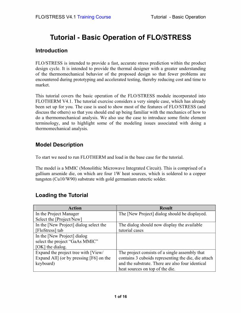
Action Result Open the Drawing Board
Check the grid by pressing [G] on the keyboard.
As you would expect, the grid has been concentrated around the heat sources.
It is important to note that whereas FLOTHERM solves in every grid cell in the project, FLO/STRESS only solves in solid cells (elements in finite element terminology).
Accessing the FLO/STRESS Dialogs The FLO/STRESS dialogs are under the [Project/Auxiliary Variables] dialog in the Project Manager. To get access to this dialog we have to have the variable fields stored in memory. That means we need to have solved or re-initialized. To perform a thermomechanical analysis we need to have the temperature field initialized or solved, as FLO/STRESS calculates thermally-induced stresses and strains due to thermal expansion and contraction.
Action Result In the Project Manager, select [Project/Re-Initialize]
This initializes the temperature field to the global ambient temperature.
2 of 16
FLO/STRESS V4.1 Training Course Tutorial - Basic Operation
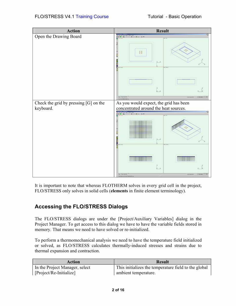
Action Result In the [Project/Auxiliary Variables] dialog: Select [Stress] in the list. Click on [Calculate].
[Stress Data] dialog is displayed:
The FLO/STRESS Dialogs
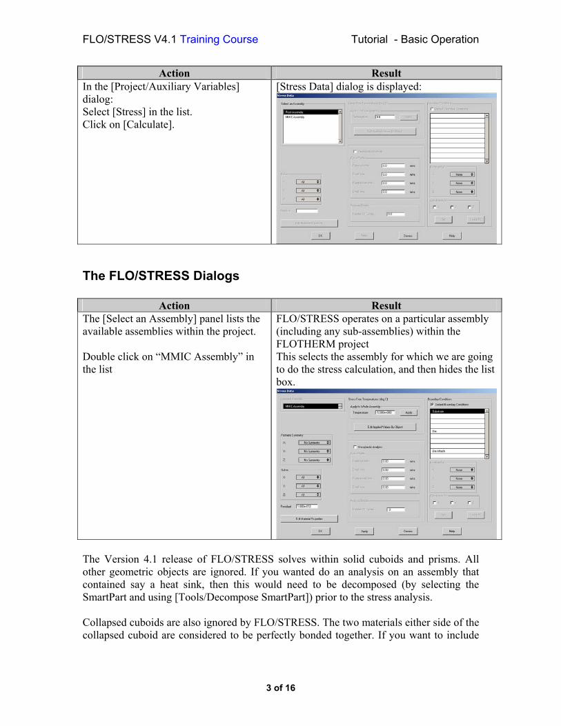
Action Result The [Select an Assembly] panel lists the available assemblies within the project. Double click on “MMIC Assembly” in the list
FLO/STRESS operates on a particular assembly (including any sub-assemblies) within the FLOTHERM project This selects the assembly for which we are going to do the stress calculation, and then hides the list box.
The Version 4.1 release of FLO/STRESS solves within solid cuboids and prisms. All other geometric objects are ignored. If you wanted do an analysis on an assembly that contained say a heat sink, then this would need to be decomposed (by selecting the SmartPart and using [Tools/Decompose SmartPart]) prior to the stress analysis. Collapsed cuboids are also ignored by FLO/STRESS. The two materials either side of the collapsed cuboid are considered to be perfectly bonded together. If you want to include
3 of 16
FLO/STRESS V4.1 Training Course Tutorial - Basic Operation
this layer in the stress analysis you need to uncollapse the cuboid. This can be done after the thermal calculation.
Entering the Data for FLO/STRESS
Action Result In the [Stress-Free Temperatures] panel Set the [Temperature:] field to 355 and click on the [Apply] button.
This is the temperature at which the assembly is fabricated (i.e. the die bonding temperature). The relevance of this is discussed later when we look at the results. Clicking the [Apply] button should set the stress-free temperature for all objects to this value.
Click on the [Edit Applied Values by Object] button
This opens the [Stress-Free Temperatures] dialog. Individual items can be reset by double clicking on the temperature value in the [Temp] column, typing in the new value and the hitting the [Return] key.
[Cancel] the [Stress-Free Temperatures] dialog.
Before we finish with the [Stress Data] dialog, note that the [Boundary Conditions] panel shows the [Default Boundary Conditions] check box is checked on. We will discuss the relevance of this later.
Material Data for FLO/STRESS FLO/STRESS knows what materials are present in the assembly being solved.
Action Result Click on the [Edit Material Properties] button
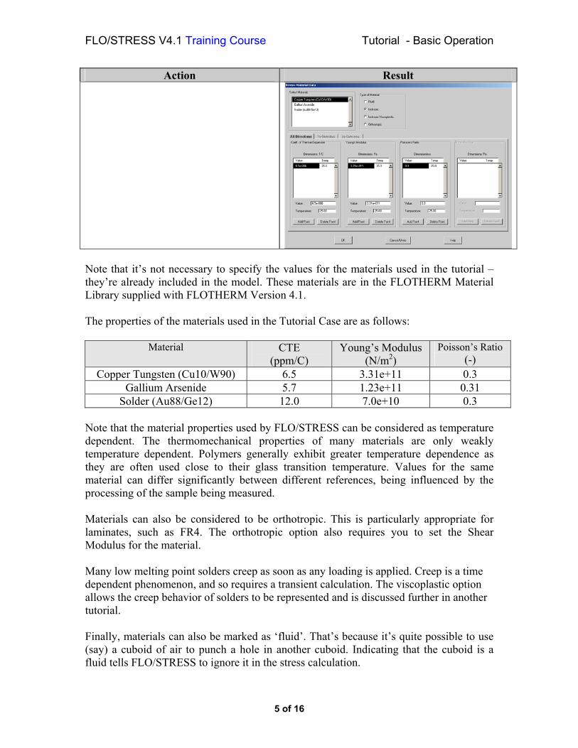
The [Stress-Material Data] dialog should be displayed:
4 of 16
FLO/STRESS V4.1 Training Course Tutorial - Basic Operation
Action Result
Note that it’s not necessary to specify the values for the materials used in the tutorial – they’re already included in the model. These materials are in the FLOTHERM Material Library supplied with FLOTHERM Version 4.1. The properties of the materials used in the Tutorial Case are as follows:
Note that the material properties used by FLO/STRESS can be considered as temperature dependent. The thermomechanical properties of many materials are only weakly temperature dependent. Polymers generally exhibit greater temperature dependence as they are often used close to their glass transition temperature. Values for the same material can differ significantly between different references, being influenced by the processing of the sample being measured. Materials can also be considered to be orthotropic. This is particularly appropriate for laminates, such as FR4. The orthotropic option also requires you to set the Shear Modulus for the material. Many low melting point solders creep as soon as any loading is applied. Creep is a time dependent phenomenon, and so requires a transient calculation. The viscoplastic option allows the creep behavior of solders to be represented and is discussed further in another tutorial. Finally, materials can also be marked as ‘fluid’. That’s because it’s quite possible to use (say) a cuboid of air to punch a hole in another cuboid. Indicating that the cuboid is a fluid tells FLO/STRESS to ignore it in the stress calculation.
5 of 16
FLO/STRESS V4.1 Training Course Tutorial - Basic Operation
Action Result
Click on the [Cancel] button to close the [Stress-Material Data] dialog.
The [Stress-Material Data] dialog should be closed. The [Stress Data] dialog should be displayed.
Starting the FLO/STRESS Solution We are now in a position to start a FLO/STRESS solution. Before we do, there are a couple of things worth pointing out, and some changes to make: First, finite element calculations typically require much more memory than CFD calculations on a per-element (cell) basis. The solution is a coupled calculation of the displacements in the three co-ordinate directions. Some time is spent at the beginning of the calculation building the system matrix and the pre-conditioner before the first iteration starts. Second, finite element calculations generally take many iterations to get to the solution. FLO/STRESS constructs its own unstructured FE mesh, replicating the FLOTHERM mesh within cuboids and prisms below the target assembly.
Modifying the FLO/STRESS Model As the stress calculation is quite numerically intensive, we should try to ensure that we are doing everything we can to minimize the computational burden. How well the model is constrained has quite a big effect on the solution time. We have used the default boundary condition option. By default, FLO/STRESS fixes just one node (being the cell vertex) in the model in all three co-ordinate directions (which prevents the model from translating, and two adjacent nodes in one and two co-ordinate directions respectively, preventing the model from rotating and tilting. It’s as if the assembly is just hanging in space, and not fixed to anything. This is the weakest possible constraint we can apply, and correspondingly the slowest to converge. It would be much more sensible to consider what the model is actually fixed to, and then apply a more physically-realistic constraint. In this case, we shall consider the whole of the bottom surface of the substrate to be constrained in the vertical direction. Another factor that affects how fast we get to the solution, both in terms of the number of iterations and time per iteration is the number of elements in the model. If the targeted assembly has geometry and boundary conditions that are symmetric through the assembly in one or two co-ordinate directions, we can exploit this, and arrange to solve only a half or a quarter of the assembly provided a grid line coincides with these symmetry planes. In this case, the assembly and its boundary conditions are symmetric in both the x- and z-
6 of 16
FLO/STRESS V4.1 Training Course Tutorial - Basic Operation
directions. These symmetry conditions, together with fixing the bottom of the substrate in the vertical direction adequately constrain the model. If they did not, we would get a message from FLO/STRESS to that effect when we tried to solve. Finally, the residual we are trying to converge down to also has an influence on the time it takes to get to the solution. If it is set too low, or the case does not converge well, the solver will keep on iterating and eventually stop when the number of iterations reaches twice the number of degrees of freedom in the model – that’s 6 times the number of nodes in the model. The current residual value of 1.E-12N is very low. 1.E-4N to 1.E-6N is typically sufficient for engineering accuracy. Let’s go back and modify the FLO/STRESS inputs as described above so we get to the solution faster.
Action Result In the [Solve] panel, Set the [X:] choice box to [X-High] Set the [Z:] choice box to [Z-High]
These settings arrange to solve the x-high z-high quadrant of the assembly.
In the [Boundary Conditions] panel, check off the [Default boundary condition] check box.
This activates the rest of the [Boundary Conditions] panel.
With “Substrate” selected in the list box, In the [Constraint on:] panel, set the [Y:] choice box to [Y-Low]
This arranges to constrain the y-low face of the substrate in the y-direction.
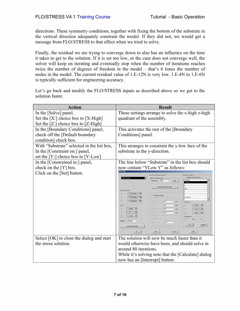
In the [Constrained in:] panel, check on the [Y] box. Click on the [Set] button.
The line below “Substrate” in the list box should now contain “YLow Y” as follows:
Select [OK] to close the dialog and start the stress solution.
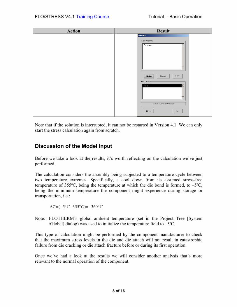
The solution will now be much faster than it would otherwise have been, and should solve in around 80 iterations. While it’s solving note that the [Calculate] dialog now has an [Interrupt] button:
7 of 16
FLO/STRESS V4.1 Training Course Tutorial - Basic Operation
Action Result
Note that if the solution is interrupted, it can not be restarted in Version 4.1. We can only start the stress calculation again from scratch.
Discussion of the Model Input Before we take a look at the results, it’s worth reflecting on the calculation we’ve just performed. The calculation considers the assembly being subjected to a temperature cycle between two temperature extremes. Specifically, a cool down from its assumed stress-free temperature of 355ºC, being the temperature at which the die bond is formed, to –5ºC, being the minimum temperature the component might experience during storage or transportation, i.e.:
CCCT °−=°−°−=∆ 360)3555( Note: FLOTHERM’s global ambient temperature (set in the Project Tree [System
/Global] dialog) was used to initialize the temperature field to –5ºC. This type of calculation might be performed by the component manufacturer to check that the maximum stress levels in the die and die attach will not result in catastrophic failure from die cracking or die attach fracture before or during its first operation. Once we’ve had a look at the results we will consider another analysis that’s more relevant to the normal operation of the component.
8 of 16
FLO/STRESS V4.1 Training Course Tutorial - Basic Operation
Looking at the FLO/STRESS Results
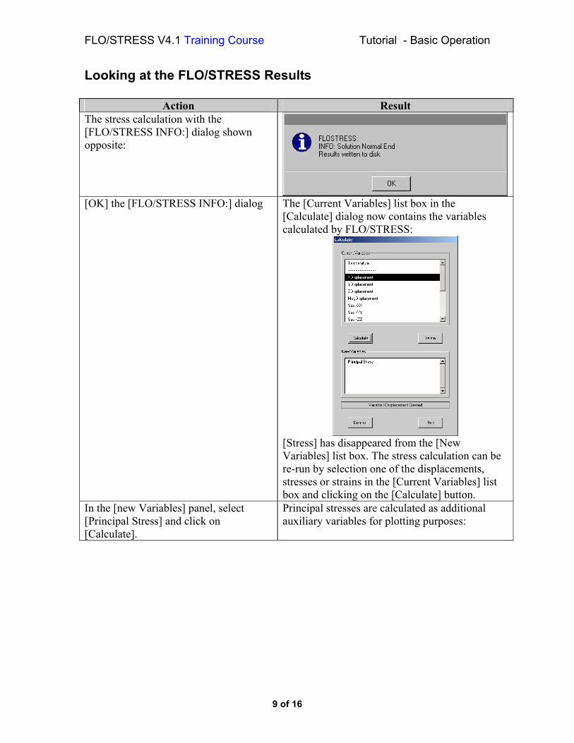
Action Result The stress calculation with the [FLO/STRESS INFO:] dialog shown opposite:
[OK] the [FLO/STRESS INFO:] dialog The [Current Variables] list box in the [Calculate] dialog now contains the variables calculated by FLO/STRESS:
[Stress] has disappeared from the [New Variables] list box. The stress calculation can be re-run by selection one of the displacements, stresses or strains in the [Current Variables] list box and clicking on the [Calculate] button.
In the [new Variables] panel, select [Principal Stress] and click on [Calculate].
Principal stresses are calculated as additional auxiliary variables for plotting purposes:
9 of 16
FLO/STRESS V4.1 Training Course Tutorial - Basic Operation
Action Result
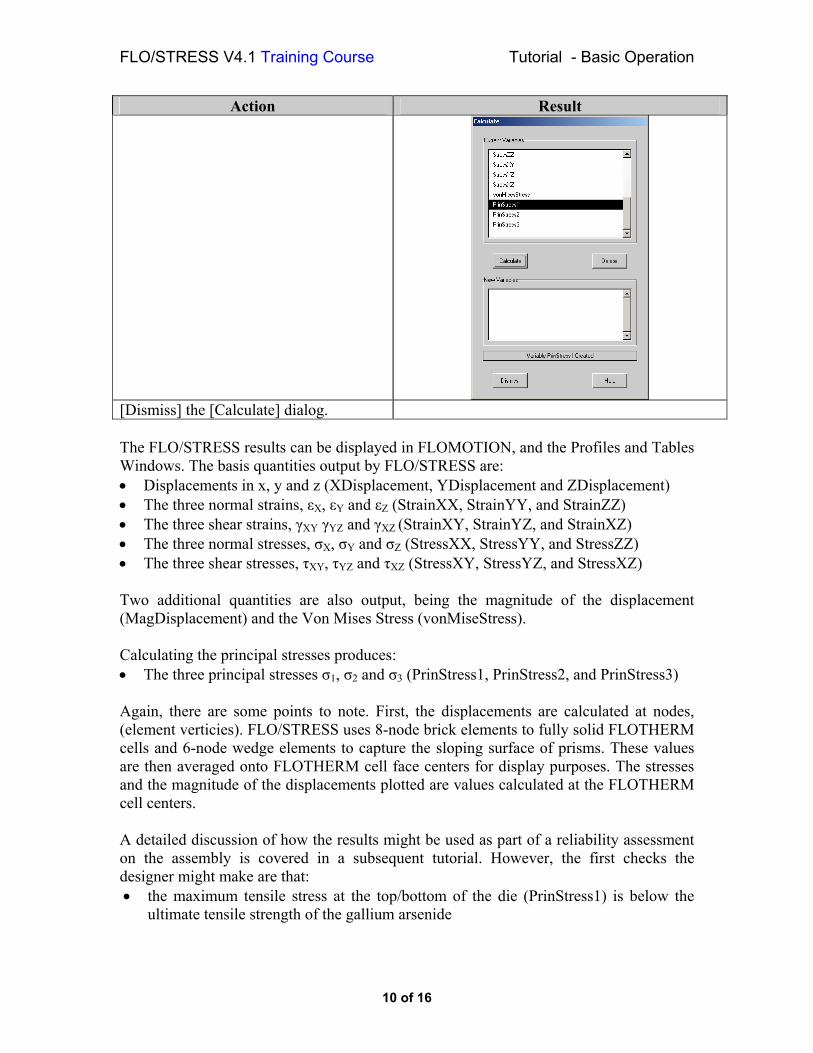
[Dismiss] the [Calculate] dialog. The FLO/STRESS results can be displayed in FLOMOTION, and the Profiles and Tables Windows. The basis quantities output by FLO/STRESS are: • Displacements in x, y and z (XDisplacement, YDisplacement and ZDisplacement) • The three normal strains, εX, εY and εZ (StrainXX, StrainYY, and StrainZZ) • The three shear strains, γXY γYZ and γXZ (StrainXY, StrainYZ, and StrainXZ) • The three normal stresses, σX, σY and σZ (StressXX, StressYY, and StressZZ) • The three shear stresses, τXY, τYZ and τXZ (StressXY, StressYZ, and StressXZ) Two additional quantities are also output, being the magnitude of the displacement (MagDisplacement) and the Von Mises Stress (vonMiseStress). Calculating the principal stresses produces: • The three principal stresses σ1, σ2 and σ3 (PrinStress1, PrinStress2, and PrinStress3) Again, there are some points to note. First, the displacements are calculated at nodes, (element verticies). FLO/STRESS uses 8-node brick elements to fully solid FLOTHERM cells and 6-node wedge elements to capture the sloping surface of prisms. These values are then averaged onto FLOTHERM cell face centers for display purposes. The stresses and the magnitude of the displacements plotted are values calculated at the FLOTHERM cell centers. A detailed discussion of how the results might be used as part of a reliability assessment on the assembly is covered in a subsequent tutorial. However, the first checks the designer might make are that: • the maximum tensile stress at the top/bottom of the die (PrinStress1) is below the
ultimate tensile strength of the gallium arsenide
10 of 16
FLO/STRESS V4.1 Training Course Tutorial - Basic Operation
• the maximum compressive stress at the top/bottom of the die (PrinStress3) is below the ultimate compressive strength of the gallium arsenide, and
• the Von Mises stress in the die attach does not exceed the modulus of rupture of the gold germanium solder
Obviously to do that you need to know the ultimate tensile/compressive strength of the gallium arsenide and the modulus of rupture of the solder. The designer would then go on to consider the initiation and propagation of micro cracks on the die surface as a failure mechanism.
Displaying The Results In this calculation, the assembly is cooled below its stress-free temperature. The copper tungsten is very stiff (having a high Young’s modulus) and has a CTE that is slightly greater than the gallium arsenide. As it contracts more, it acts to compress the die. Between the two is the gold germanium solder. It has a higher CTE than both the copper tungsten and the gallium arsenide. It contracts more than either the die or the substrate, and so is held in tension by the two materials either side of it. Although the solder contracts more than the substrate, it is much less stiff. The net effect is that the die experiences less compression than it would if it were directly bonded to the substrate. Reducing stresses in the die is part of the solder’s role.
Action Result In the Project Manager start the FLOMOTION Window
In FLOMOTION select [Editors/Plot Editor]
The [Plot Editor] window should be displayed.
In the [Plot Editor] window select the [Create] button
This creates a new plane-type plot
In the [Plane] panel set radio button to [Z].
This sets the plane to be normal to the z-direction.
In the [Scalers] panel [Display Scalar] check box. Set choice box to [StressXX]
This creates a plane of StressXX
In the [Plane] panel set the [Unit] choice box to [mm]. Set the field adjacent to the slider bar to 4 and hit [Return]
The field should display 4.00. 3.5mm is the centerline of the assembly in the z-direction so this is just into the part that’s been solved.
In [Clip/Wireframe Geometry] panel set the [Above] choice box to [Wireframe]
This sets make the geometry in from of the display plane transparent, so we can see the values.
11 of 16
FLO/STRESS V4.1 Training Course Tutorial - Basic Operation
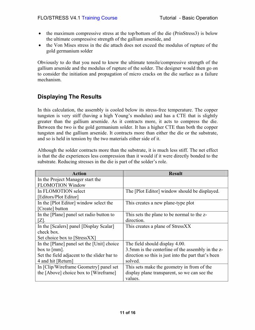
Action Result
Orient the model so the stress in the assembly can be clearly seen using the thumb wheels in the lower left-hand corner of the FLOMOTION window, and zoom in using the thumb wheels in the lower right-hand corner of the window.
The die can be seen to be in compression (negative stress) and the solder is in tension (positive stress):
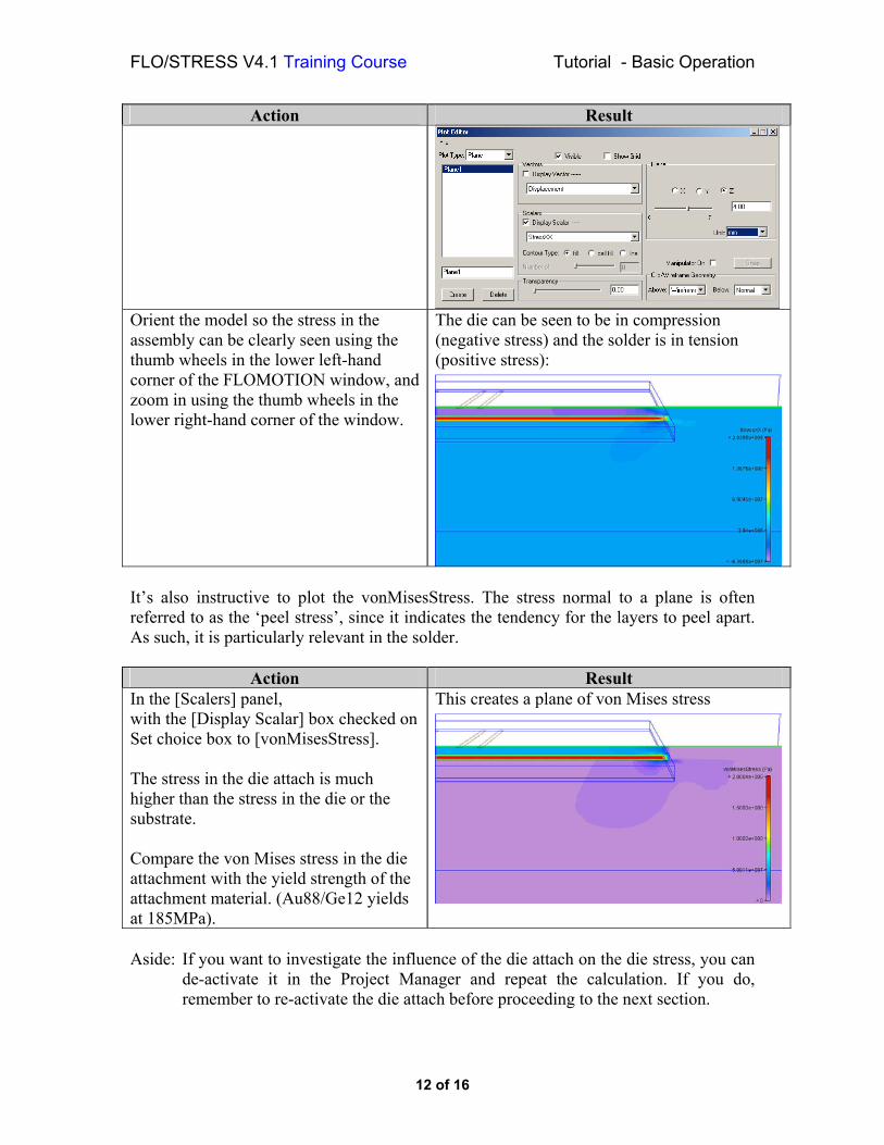
It’s also instructive to plot the vonMisesStress. The stress normal to a plane is often referred to as the ‘peel stress’, since it indicates the tendency for the layers to peel apart. As such, it is particularly relevant in the solder.
Action Result In the [Scalers] panel, with the [Display Scalar] box checked on Set choice box to [vonMisesStress]. The stress in the die attach is much higher than the stress in the die or the substrate. Compare the von Mises stress in the die attachment with the yield strength of the attachment material. (Au88/Ge12 yields at 185MPa).
This creates a plane of von Mises stress
Aside: If you want to investigate the influence of the die attach on the die stress, you can
de-activate it in the Project Manager and repeat the calculation. If you do, remember to re-activate the die attach before proceeding to the next section.
12 of 16
FLO/STRESS V4.1 Training Course Tutorial - Basic Operation
Performing a Thermomechanical Analysis for a Functional Cycle The equipment manufacturer is more interested in the lifetime of the equipment, and so wants to know how long the component will operate before it fails through some fatigue (or wear out) mechanism. Wear out is caused by the component being cycled through its expected operating temperature range, with the magnitude of the temperature cycle driving the failure. In the following example, wear out might include die fracture or die attach delamination via a crack propagation mechanism. To calculate the stresses and strains that cause wear out, the equipment is often considered to be stress free in its powered-off state, at the minimum ambient temperature the equipment will experience in practice (say +5ºC). Thus:
CCTT Operating °+≈°−=∆ 130)5( This is a radically different from assuming its stress free at 355ºC isn’t it! The rationale is that after a substantial period of operation, the stresses frozen-in at the die bond temperature are gradually relieved as the solder creeps over time. Eventually, the effective stress free temperature of the assembly might be expected to be within its operating temperature range, and closer to the powered on state. Assuming that the assembly is in its stress free state when powered off is therefore conservative. We will employ this assumption. For the thermal boundary conditions, the model has a high heat transfer coefficient applied to the bottom of the copper tungsten block to represent the heat sinking effect of the rest of the environment with the temperature set to the maximum operating ambient of 50ºC.
Performing the Thermal Calculation Before we can do the stress calculation we have to perform the thermal calculation, so let’s do that now.
Action Result In the Project Manager Click on [Project/Solve]
The solution should only take a few outer iterations.
Although this is a conduction only calculation, it does put the numerical intensity of the stress calculation in perspective.
13 of 16
FLO/STRESS V4.1 Training Course Tutorial - Basic Operation
Re-running the Stress Calculation
Action Result Launch the [Stress Data] dialog as before. In the [Select an Assembly] panel double click on “MMIC Assembly”
In the [Stress-free Temperatures] panel In the [Default Temperature] field Set the [Temperature:] field to 5.0 and click on the [Apply] button.
The list of temperatures should now all show 5.0 as the stress free temperature.
[OK] the [Stress Data] dialog The stress solution should start.
Viewing the Results
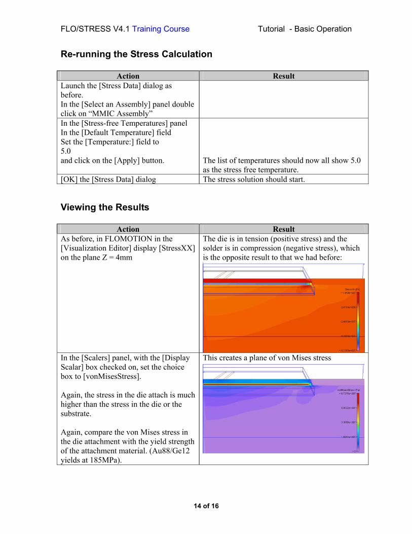
Action Result As before, in FLOMOTION in the [Visualization Editor] display [StressXX] on the plane Z = 4mm
The die is in tension (positive stress) and the solder is in compression (negative stress), which is the opposite result to that we had before:
In the [Scalers] panel, with the [Display Scalar] box checked on, set the choice box to [vonMisesStress]. Again, the stress in the die attach is much higher than the stress in the die or the substrate. Again, compare the von Mises stress in the die attachment with the yield strength of the attachment material. (Au88/Ge12 yields at 185MPa).
This creates a plane of von Mises stress
14 of 16
FLO/STRESS V4.1 Training Course Tutorial - Basic Operation
Aside: If you want to investigate the influence of the mechanical boundary conditions on the die attach stress, you can set the boundary conditions to default in the StressData dialogue. This is a mechanical change only.
Otherwise you can investigate the effects of the thermal environment on the die attach stress by changing the power of the sources, changing the ambient temperature or by changing the heat transfer coefficient on the YLow surface of the block. These are thermal changes only.
Otherwise you could investigate the effects of changing materials, for example the substrate could be replaced with Silicon Carbide, Kovar or Aluminum Nitride, the die could be replaced with Silicon, or the solder could be replaced by Au80/Sn20 or Sn63/Pb37. These are both thermal and mechanical changes.
Final Comments on the Tutorial Hopefully you will have found the mechanics of using FLO/STRESS easy to master. However, if thermomechanical analysis is something you haven’t done before there are quite a lot of modeling issues to get to grips with. Under ‘What Next’ below we’ve put down some ideas that might help get you started. We performed two quite different analyses on the assembly, using different assumptions about the stress-free temperature. We also made an assumption about the way the bottom of the package is held. These assumptions have a big influence on the results of the calculation. Getting reliable material property data is another issue that affects the accuracy of the calculation we can be performed, particularly for solders, plastics and laminates. FLO/STRESS itself has some limitations. It can only handle cuboids and prisms at present, and the calculation can not be restarted. Earlier we mentioned creep as a mechanism of stress relaxation in the solder, which merits some further discussion. This example considers a hard solder, but lower melting point solders used to connect packages to PCBs are much more prone to plasticity and creep. These effects can be modeled performing a visco-plastic calculation. A transient analysis is required for which more material property data is needed. Such analyses need to be run for several temperature or functional cycles to predict the full effects of the plasticity and creep. Consequently such calculations tend to be restricted to the study of individual solder balls/joints. Fortunately low melting point solders tend to be much less stiff than the package and board materials they bond together, and so their deformation is dictated by the behavior of these objects, so that the total strain they experience can be predicted with reasonable accuracy. Solder joint fatigue can be considered as a strain driven process, or as an
15 of 16
FLO/STRESS V4.1 Training Course Tutorial - Basic Operation
energy driven process. Hence there are a number of practical approaches to estimating the life of a solder joint.
What Next? The FLO/STRESS Lecture Course provides further information on a number of the topics discussed above. A further tutorial ‘Solder Joint Life Prediction’ is available. The FLO/STRESS Reference List gives a number of useful references. Visit www.flotherm.com follow the User Support link and then under Support select the FLO/STRESS Center.