Great Lakes Carbon Corporation founded the continuous petroleum coke calcining industry with the
start-up of the company’s first rotary kiln in 1935, the world’s first rotary kiln used for the purpose of
creating a product high in carbon purity for use in making anodes for aluminum smelting. Thistutorial paper will describe the transformation of the petroleum coke calcining industry from the
fledgling early days of the Great Depression to the competitive global industry of today. The coke
calcining process will be described in detail. Modern calcining technology in use at a typical calcining
plant will be presented. A summary of the properties desired for each of the uses of calcined
petroleum coke will be included. Process overviews will be shown for each of the industries that use
calcined petroleum coke including aluminum smelting, graphite electrode manufacturing, TiO2
processing, chemical processing, and steel production.
Petroleum coke is calcined (roasted at high temperatures, 1200 to 1350°C) usually in a gas-fired
rotary kiln or rotary hearth to remove moisture, drive off volatile matter, increase the density of the
coke structure, increase physical strength, and increase the electrical conductivity of the material. The
result is a hard, dense carbon (calcined petroleum coke) with low hydrogen content and goodelectrical conductivity. These properties along with low metals and ash contents make calcined
petroleum coke the best material currently available for making carbon anodes for smelting of alumina
to aluminum.
HISTORY OF THE PETROLEUM COKE CALCINING INDUSTRY
The Early Days of Coking
A byproduct of petroleum refining, petroleum coke initially came from several different types of
operations. From early refining with small iron stills to the horizontal batch stills of the 1860-1880’s,
through the introduction of the tube furnace and distillation columns in the 1920’s, and thermalcracking process introduced in the 1920’s, the delayed coking process was developed. In all of these
early methods of refining and thermal cracking, petroleum coke was produced.
Batch Still Coking. Shortly after the discovery of crude oil in Pennsylvania, early “refineries”
which boiled crude oil in small wrought iron stills to recover kerosene produced the first petroleum
coke in the 1860’s. The stills were heated by wood or coal fires built underneath which over-heated
and coked the oil near the bottom. After the distillation was completed, the still was allowed to cool
so the workmen could dig out the coke and tar before the next run [Conners 1981]. The early batch
stills led to the use of single horizontal shell stills for distillation of crude oil which continued through
the 1880's. Multiple horizontal stills were used to process more fractions by running the stills in series
with the first still producing the coke. These horizontal stills were fired mostly with coal or some of
the petroleum coke. Horizontal batch still coke was removed through an opening at the end of the
horizontal tank with relays of men wrapped up in rags to protect against the heat using picks, shovels,
and wheelbarrows. Horizontal batch still coke was 150 to 750 mm thick and had a glossy luster, low
volatile matter (~8 wt%), low moisture (<1 wt%), ash content of ~1 wt%, and after removing was
mostly lumps with only a small amount of fines.
In the 1920's, the tube furnace and distillation columns were introduced. Crude oil was heated
in the tube furnace and proceeded to the distillation column. The bottoms (reduced crude or
residuum) from the distillation column was charged to horizontal batch stills previously described.
This produced a maximum amount of heavy gas oil. Some of these units were still in operation after
World War II and required the same manual decoking as described above [Ellis and Paul, 1998].
Thermal Cracking. Vertical soaking drums were first used in the thermal cracking of gas oil
for the production of gasoline and diesel fuel. In the 1920’s, Dubbs at Universal Oil Products (UOP)
developed a thermal cracking process to produce gasoline from heavy gas oil. This thermal cracking
process was operated at higher pressures and coke was formed in a vertical soaking drum. The units
were called “Dubbs” units or cracking stills. The three meter (10 ft) diameter by 12.2 m (40 ft) high
vertical soaking drum had a bottom manhole in which the coke was extracted. Over 1219 m (4000 ft)
of steel cables 22 mm (7/8 inch) diameter were wrapped around inside the drum by hand and fastened
to small ears on the drum walls. At the end of the thermal cracking run, the cables were pulled out to
dislodge the coke. Any coke remaining on the walls was manually cleaned off before re-wrapping the
cable inside the drum. This thermal cracking still coke had higher volatile matter, smaller sizing(contained a large amount of fines), and was considered to be a poor quality coke compared to the
lumpier batch still coke [Swanson 1930].
Delayed Coking. The vertical cracking stills were the forerunners of the delayed coking
process. The first “modern” delayed coker was built by Standard Oil at Whiting, Indiana in 1929.
Delayed coking combined a number of the features and improvements from thermal cracking. The
use of pressure as well as heat for cracking, separating the heater from the coke drums, and the use of
two drums enabled the delayed coker to operate on a continuous basis. Lack of an adequate supply
of crude oil and the lack of a heavy oil market caused land-locked Midwest refineries to process the
heavy fuel oil (atmospheric distillation bottoms and vacuum distillation bottoms) in a delayed coker to
produce more gasoline and diesel fuel. Decoking the drums was difficult. “Manual decoking was ahot and dirty job. …Various mechanical devices were tried. One of the common systems employed
was to wind several thousand feet of steel cable on holding devices in the drum. A cable was pulled
with a winch to loosen the coke. Coke was also removed by drilling a small hole, then a large hole,
after which beater balls on a rotating stem knocked out the remaining coke [Conners 1981].” The
development of hydraulic decoking which uses high-pressure water pumped through a drill pipe and
cutting bit to cut the coke from the drums came in the late 1930's. Standard Oil at Whiting was one of
the early developers of hydraulic decoking.
The Growth of Delayed Coking versus Fluid Coking. The number of delayed cokers built
from 1929 to 1955 was small, but a surge in delayed coker construction took place between 1955 and
1975 [Conners 1981]. The growth of delayed coking kept pace with the growth of fluid catalyticcracking and the rapid decline in thermal cracking. A fluid coker, similar to a fluid catalytic cracker
except that fluid coke is circulated instead of catalyst, was first built in 1954 at Billings, Montana.
Five more fluid cokers were built in the late 1950’s, and one in 1970. In the late 1950’s, some
thought that all new cokers built would be fluid cokers [Ellis and Paul, 1998]. Due to the lower
capital cost, delayed coking became and still is the coking process preferred by many refiners. Today
there are 50 operating delayed cokers in the U.S. and only six fluid cokers / flexicokers.
Early Coke Marketing / Great Lakes Carbon Corporation
Great Lakes Carbon Corporation was formed originally as Great Lakes Coal & Coke Company by
George Skakel, Sr. in partnership with Walter Gramm primarily to broker coal in 1919. Later in
1939, the company was incorporated as Great Lakes Carbon Corporation. In addition to trading
coal, during the late 1920’s, Great Lakes Carbon (GLC) became actively interested in petroleum
coke. As you can recall from the previous sections, petroleum coke at this time was made by the
horizontal batch still and thermal cracking still processes.
As thermal cracking processes became popular in the 1920’s, the quantity of the thermal cracking still
coke grew rapidly causing problems with disposal [Swanson 1930]. Mountainous storage piles of
petroleum coke, amounting to several million tons, accumulated in Texas and adjacent coastal and
interior refineries as well as at other refineries throughout the U.S. This petroleum coke with low ash
content, <0.5 wt%, and a high heating value, ~37.1 J/kg (16,000 BTU/lb) resembled both bituminous
mine coal and slot oven byproduct metallurgical coke. As a result of the lack of market for this newrefining byproduct, the problem of petroleum coke storage became an acute one at many refineries.
Petroleum coke created handling expense, took up valuable storage space within the refineries, and
added to the fire hazards around the refineries [Watkins 1937].
In the early days, many refineries were often so desperate to get rid of petroleum coke due to the fire
hazards and handling problems that some refineries actually paid GLC to take the coke off their
hands. Refineries were very happy when they were able to sell the coke, even if it was for a low
price. In 1932, GLC entered into handshake agreements with practically all of the refiners to
purchase coke and concentrate its efforts on creating a market for petroleum coke. Large plants were
constructed for cleaning, sizing, screening and transferring coke at port and rail terminals. These
efforts resulted in completely liquidating the storage piles of what was a burdensome and practicallyvalueless product [Watkins 1937]. Some of the early uses of petroleum coke were home heating and
industrial heating (for the lumps) and burning with coal at power plants (for the fines). The biggest
market was along the Atlantic coast, but this fuel coke market quickly spread to Europe and
worldwide in a short time [Hardin and Gehlbach, 1992].
Birth of Continuous Petroleum Coke Calcining
In searching out uses for petroleum coke, it was found that certain foreign and domestic consumers
required a material having the highest value of fixed carbon. The largest such market was for making
carbon anodes for the aluminum industry. Calcined coal was being used as the carbon source at the
time. To meet this demand for higher purity carbon, GLC installed a unique plant in Port Arthur,Texas using raw petroleum coke as its raw material [Watkins 1937].
Before 1935, some petroleum coke was calcined batch-wise in slot ovens similar to units used to
calcine coal. Attempts had been made at calcining petroleum coke (lump only) in vertical shaft kilns
by passing hot combustion gases up through a moving bed of coke, but there were many problems
with this type of system. A small amount of coke was calcined in electric furnaces, but this was an
expensive process [Hardin and Gehlbach, 1992]. GLC hired a professor from the University of
Illinois in 1934 who thought that petroleum coke could be continuously calcined in a rotary kiln
similar to kilns being used in the lime and cement industries.
In the middle of the Great Depression, GLC decided to test the idea and purchased a used lime kiln in
Canada. The kiln was shipped to Port Arthur, Texas on a barge through the inter-coastal waterway
and was set up on waterfront property leased from the railroad. Several million tons of raw petroleum
coke were on the ground at a nearby Texaco refinery. The rotary kiln was started up in October 1935
becoming the first rotary kiln in the world to continuously calcine petroleum coke. The calcined coke
was stored in an old wooden cotton storage shed. Loading calcined product in the first ship in 1936
was a very labor-intensive process. Workers loaded wheelbarrows by hand and pushed them up
gangplanks to the ship.
Growth of the Petroleum Coke Calcining Industry
As the use of calcined petroleum coke in making anodes for the aluminum industry was provencommercially, the demand for calcined coke escalated dramatically. GLC built new kilns and
calcining plants at a very rapid pace with six new kilns coming on-line from 1937 to 1943. Growth in
delayed coker construction from 1955 to 1975 also fueled the growth of petroleum coke calcining
into the early 1970’s with eleven more GLC kilns starting up from 1952 to 1972. A few competitors
(refiners, aluminum smelters, and other independent calciners) also began to build calcining plants to
enter the anode grade calcined petroleum coke market in the 1950’s.
“Needle Coke” Calcining / Graphite Electrodes. Another development in the 1950’s that
spurred the growth of petroleum coke calcining was the development of synthetic graphite from a
special kind of petroleum coke called “needle coke”. GLC discovered and patented [Shea 1956] this
special petroleum coke that could be produced by delayed cokers and calcined for use in makinggraphite electrodes used in steel arc furnaces. As steel mini-mills became popular, a rise in demand for
graphite electrodes and green needle coke prompted many refiners to produce needle coke in blocked
operations. Specifications for needle coke are quite stringent and require special coking and special
calcining as is described later in this paper. Early on some refiners, and later, independent
coker/calciners and steel producers (mostly in Japan) were able to enter the calcining industry to
produce needle coke.
As crude oil supplies to refineries began to increase in sulfur in the 1970’s, many refiners were
unable to meet the sulfur specifications for (high quality) non-puffing needle coke and were gradually
forced out of the market. As some of the refiners left, a few independent coker/calciners entered the
industry to capture this niche market by coking special coker feedstocks that could still meet needlecoke specifications. As graphite electrode quality improved and mini-mills became more efficient in
their use of graphite electrodes, the demand for calcined needle coke decreased in the late 1980’s.
This downturn in demand caused a few players to drop out, but enabled the remaining participants to
actually increase production and remain competitive. Today, all the producers of premium green
needle coke also calcine their own coke.
Petroleum Coke Calcining Industry Today. Today, a fiercely competitive global petroleum
coke calcining industry exists. GLC, the world’s largest producer of calcined petroleum coke (CPC)
with production capacity of over 1.6 million tons, has nine operating rotary kilns at three locations:
Port Arthur, Texas (4 kilns); Enid, Oklahoma (3 kilns); and La Plata, Argentina (2 kilns). In the total
industry, approximately 30 producers of CPC include refiners, smelters, independent calciners,
independent coker/calciners, graphite electrode manufacturers, and steel producers. Global expansion
of the industry has resulted in the establishment of calcining operations in Canada, Argentina, Brazil,
United Kingdom, Germany, Norway, Spain, South Africa, the Middle East, India, Indonesia, Japan,
China, and Russia [Martinez and Bartholomew, 1998].
There are two primary methods of continuous calcination of petroleum coke, the rotary kiln and the
rotary hearth furnace. These two methods are described in detail in this paper. To our knowledge,
there is only one other method in use today for calcining coke. Located in Russia, it is a special type
of heated wall vertical shaft calciner (sort of like a moving slot oven) that can produce a good densitycoke. The operating cost is higher than a rotary kiln or hearth, but the slower up-heat rates allow
them to use higher volatile matter green coke to achieve similar calcined densities.
Rotary Kiln
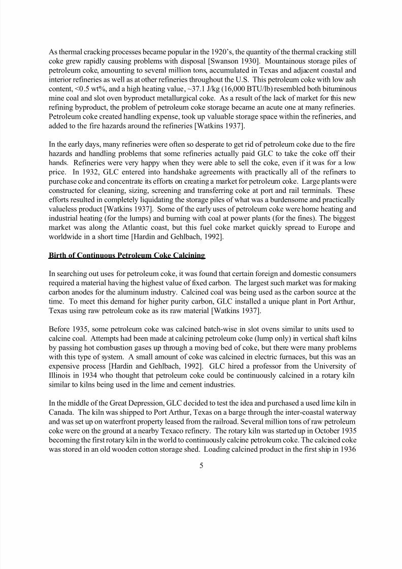
Kiln. Most petroleum coke is calcined in a rotary kiln. A schematic of a coke calcining plant
using a rotary kiln is shown in Figure 1 [Bagdoyan and Gootzait, 1985]. A rotary kiln is a rotating
horizontal cylinder 2.5 to 5 meters in diameter and 50 to 80 meters long lined with 0.23 m thick
special high-temperature refractory brick. The kiln shell is made of steel 25 mm thick with the section
under the kiln tires 50 to 75 mm thick. The kiln shell is supported by the tires, which ride on two
wheels or trunions. The kiln is rotated via a large bull gear that is larger than the circumference of thekiln shell and is driven with one or two spur gears. The spur gears are driven through a gearbox by
either direct electrical drive or by hydraulic motors. The electrical drive speed is varied by either a
varying frequency or through an eddy current type clutch.
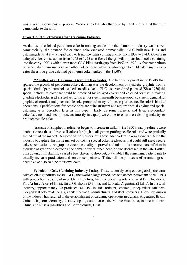
Calcining Process Flow. Raw petroleum coke is sized to 50 to 100 mm lump and fed to raw
feed silos, then to the rotary kiln (at the high end) through a side feed scoop or through a feed pipe (in
older units). The kiln is sloped downward towards the discharge end at a slope of 13 to 19 mm per
300 mm (½ to ¾ inch per foot). As the coke progresses down through the kiln counter -current to the
hot combustion gases, the temperature increases to a maximum temperature that is reached around 13
to 20 m before the discharge end of the kiln. After entering the kiln, moisture is driven off the coke in
the “Heat-Up Zone.” Devolatilization occurs mostly at 500 to 1000oC in the “Calcining Zone.”Further dehydrogenation, some desulfurization, and coke structure shrinkage (densification) take
place in the “Calcined Coke Zone” at 1200 to 1400oC (see Figure 2). The coke moves through the
kiln in 40 to 60 minutes and drops off the discharge end of the kiln into a refractory-lined chute and
into a rotary cooler.
Cooler. The cooler is a bare steel cylinder similar to the kiln but usually smaller in diameter,
shorter, and rotated at higher rpm’s than a kiln, with water sprays in the front end. Water is sprayed
to contact the hot coke, taking advantage of the very high latent heat of vaporization of the water for
cooling. Indirect water-cooled rotary cylinder coolers are used where poor water quality prevents the
use of direct cooling. The coke spends about 20 minutes in the cooler and is discharged onto high
temperature conveyor belts or into screw feeders. Computer controls adjust the water sprays to
maintain the coke at the cooler exit at ~120 to 180oC (250 to 350
oF) in order to keep the calcined
product dry.
Firing Crown and Heat Transfer. At the discharge end, the rotary kiln has a burner in the
firing crown (a hood that fits over the discharge end of the kiln) to preheat the refractory before
start-up and to supply some of the heat for calcining in most applications. Most kiln burners are
natural gas fired, but some older model kilns have oil-fired burners. Combustion air is also injected
through the firing crown. Some kilns use oxygen instead of air to reduce combustion gas flows and
to decrease or eliminate the need for gas firing. The temperature in the kiln is monitored by an optical
pyrometer focused on the discharging hot coke. The temperature is controlled by the amount of gas,
excess combustion air, kiln rotation speed, and raw coke feed. As depicted in Figure 3, almost all ofthe heat transfer to the material is by radiation from kiln gases and exposed portions of refractory
wall, and by convection from gas. A small amount of heat is transferred by conduction from the
refractory to the material [Bagdoyan and Gootzait, 1985]. Analysis of either the real density or the
electrical resistivity of the calcined coke measures the degree of calcination.
Incinerator (Pyro-Scrubber). Water vapor (from moisture of the raw coke), hot
combustion gases, unburned entrained coke fines, and unburned tars and gases (from the volatile
matter of the raw coke) flow out the feed end of the kiln into a hot incinerator or pyro-scrubber
where excess fuel and fines are burned. The incinerator (also called a combustion or settling chamber)
is operated with a negative pressure so that the kiln also operates under a slight negative pressure.
Either a tall stack or an induction fan produces the negative pressure in the incinerator if waste heat boilers (downstream of the incinerator) are used.
Tertiary (Shell) Air Injection. Since volatile matter coming off the coke during calcination
contains around twice the fuel value required for calcining, it is logical to attempt to burn this fuel for
calcining. Tertiary air (air injected through the side of the kiln from shell mounted blowers) forms a
second hot zone in the kiln that extends up toward the feed end of the kiln (see Figure 4) by burning
this volatile matter as fuel. Many rotary kilns use tertiary air for the main advantages of increased
production rates and decreased consumption of natural gas. The major disadvantage of using tertiary
air is that a faster up-heat rate in the critical range of 500 to 700°C with tertiary air [Brooks 1989]
may result in poorer coke quality (vibrated bulk density) than without tertiary air. The original
inventor of tertiary air injection is believed to have abandoned the idea for this very reason.
With special kilns and special operating practices it is possible to use tertiary air injection to
produce calcined coke of adequate quality for use in making carbon anodes. Alcan has much
experience in the use of tertiary air and claim to calcine petroleum coke without burning any natural
gas (after start-up). The Alcan kilns are long, 61 meters, and small in diameter, 2.43 m. Tertiary air
is injected 20 m (1/3 kiln length) from the discharge end. Smaller slopes and higher rotational speeds
are used than those of conventional kilns in order to increase coke bed depth and increase agitation of
the bed for a more uniform up-heat rate of the coke [Farago and Sood, 1976].
Rotary Kiln Operation. Some of the key control parameters for operating a rotary kiln to
produce good quality calcined coke include control of the up-heat rate of the raw coke and raw coke
feed consistency and sizing.
Slow Up-heat Rate is Critical. The primary objective in calcining petroleum coke for
the aluminum industry is to slowly heat the coke during the initial devolatilization around 500 to
600°C so that the mesophase or liquid crystal part of the coke does not bloat or distort (pop-corn)
during the evolution of the volatile matter. Petroleum coke with anisotropic (needle) structure and/or
high volatile matter must be calcined with slow up-heat rates in order to produce good calcined
densities and low porosity.
Lifters. Some attempts have been made using “lifters” in kilns to increase production
and keep the coke up-heat rate down by stirring the coke bed [Kaiser Aluminum 1983]. Lifters arecastable refractory or refractory bricks that stick up above the surrounding bricks. The exact location
for lifters to decrease coke up-heat rate especially in the critical 500 to 600°C range is not known for
all kilns. There is also a great problem with keeping lifters in a rotary kiln. Refractory bricks and the
steel shell of a rotary kiln both expand. Bricks must expand enough so that they are not too loose in
the kiln to prevent excess walking yet not so tight as to exceed the hot crushing strength of the brick.
Lifters get hotter at their tips, have a pinch point at the interface of the surrounding bricks, and are
subject to breaking at the interface. Several complete rings of taller bricks seem to hold together, but
the adjacent bricks on the upside become worn out due to a stagnant layer of coke that grinds down
the bricks. Lifters can also cause other problems when a coke bed is stirred too much such as
entrainment of fines in the exiting combustion gases.
Feed Consistency and Sizing. The degree of coke calcination depends mostly on
variations in the raw coke such as differences in structure, volatile matter, and particle sizing. In
rotary kilns, it has been documented that coarse particles travel faster though the kiln than the finer
particles. Some calciners have stated that coarser coke with lower quantities of fines can increase the
production rate in a kiln (enabling more tons per hour to be calcined). Without proper sizing and
feeding of a rotary kiln, slides can occur dumping most of the material rapidly out of the kiln. Rapid
devolatilization in the calcining zone tends to fluidize the coke (observed in the GLC shaking-hearth
pilot calciner). A large amount of fines in the calcining zone all at once fluidizes more readily, causing
the slides.
Rotary Hearth
The other commercial method of calcining petroleum coke is with a rotary hearth calciner. Marathon
Oil and Wise Coal and Coke Company jointly developed the rotating hearth furnace for calcining coal
and then adapted the technology for calcining petroleum coke [Merrill, Jr. 1978]. The first rotary
hearth calciners for petroleum coke were located in Europe. A simplified process flowsheet for a
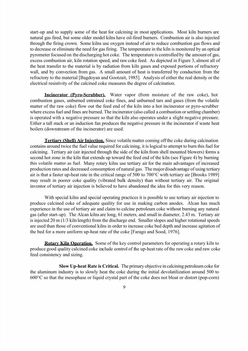
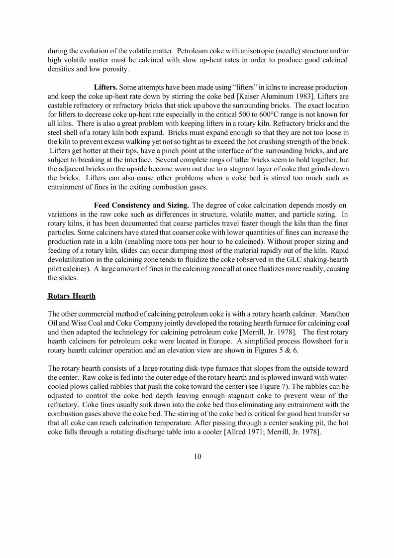
rotary hearth calciner operation and an elevation view are shown in Figures 5 & 6.
The rotary hearth consists of a large rotating disk-type furnace that slopes from the outside toward
the center. Raw coke is fed into the outer edge of the rotary hearth and is plowed inward with water-
cooled plows called rabbles that push the coke toward the center (see Figure 7). The rabbles can be
adjusted to control the coke bed depth leaving enough stagnant coke to prevent wear of the
refractory. Coke fines usually sink down into the coke bed thus eliminating any entrainment with the
combustion gases above the coke bed. The stirring of the coke bed is critical for good heat transfer so
that all coke can reach calcination temperature. After passing through a center soaking pit, the hot
coke falls through a rotating discharge table into a cooler [Allred 1971; Merrill, Jr. 1978].
Burners and combustion air nozzles are located on a stationary, suspended roof (see Figure 8) that is
connected to the rotating hearth with a seal between the two. After start-up, the rotary hearth
calciner makes use of the complete combustion of the volatile matter of the raw coke feed. Little or
no excess fuel is required for heat. The hot combustion gases coming off the top center of the roof are
used to preheat the combustion air in some hearths to further improve combustion efficiencies. The
small amount of coke fines and the volatile matter from the coke are completely consumed in the roofof the hearth, so no external incinerator is required. A schematic of the combustion process in a
rotary hearth calciner is shown in Figure 9.
Rotary Hearth Advantages Over Rotary Kiln. Some advantages of a rotary hearth
calciner are:
1) Reduced Refractory Cost - Since the refractory on the hearth is covered with a layer of coke,
there is very little wear. Refractory on the top of the kiln is stationary, eliminating problems with
brick lock and rotating forces that are present in a rotary kiln.
2) Lower Particulate Emissions - The coke fines are not entrained into the kiln exhaust.
3) Reduced Heat Losses / Less Fuel Consumption - Little or no extra fuel is required if combustion
air is preheated.
4) Elimination of Exterior Combustion Chamber for Incinerating Fines and Volatile Matter -
Complete combustion occurs within the calciner.
5) Variable Operation - Varying the turntable speed and coke bed depth can change operating
conditions and residence time over a wide range.
Disadvantages. Some of the major problems with rotary hearth calciners has been with therapid up-heat rate of the coke and calcined coke particle sizing. Rapid up-heat of the coke causes
coke structure to become bloated, distorting the structure of the coke. This leads to poor bulk
densities for the calcined product. Some of the newer rotary hearth calciners use a special shadow
wall near the raw coke inlet to help reduce the up-heat rate of the coke. Due to the nature of the
material movement through the rotary hearth, less coke fines are burned up or lost in the flow of the
combustion gases. Although this keeps particulate matter out of stack emissions, the fines remain in
the calcined product causing difficulties in meeting sizing specifications for anode grade coke. Too
many fines in the product can also cause fugitive dust problems when handling the product.
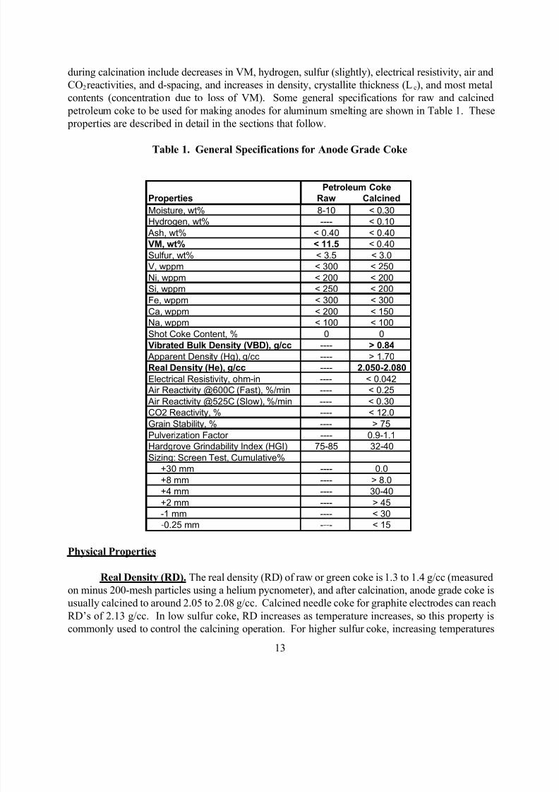
DESIRED PROPERTIES OF CALCINED COKE
Volatile matter (VM) in raw petroleum coke prevents its use in making carbon anodes with good
density, strength, and electrical conductivity. Small carbon bodies can be processed from raw coke
for some uses, but these require very elaborate processing with extremely slow up-heat rates.
Therefore, most uses other than for fuel or gasification require raw coke to be calcined in order to
improve its properties. Changes that occur in the physical and chemical properties of petroleum coke
beyond 1250 to 1300°C can actually decrease RD due to desulfurization which creates small pores in
the coke [Rhedey 1967; Hardin et al., 1993].
Electrical Resistivity. The electrical resistivity of calcined coke decreases with increasing
calcination temperature. An empirical method was set up to measure the resistivity of sized coke
particles in a ceramic cylinder with pressure (150 psi) loaded silver-plated brass rams on either end ofthe cylinder [Hardin et al., 1994]. Petroleum coke actually changes from an insulating material into a
conductor upon calcination [Hardin and Gehlbach, 1992].
Hg Apparent Density (AD). The mercury apparent density (AD) is a measurement of
porosity and density. Anisotropic, needle-type coke structure produces higher AD upon calcining
than isotropic, sponge or shot coke structures. According to Hardin et al. [1994], calcining above
1250°C decreases AD for all coke samples with the exception of one low sulfur coke that did not
decrease in AD until 1350°C. AD decreases very rapidly in high sulfur coke with the onset of
desulfurization.
Vibrated Bulk Density (VBD). Vibrated bulk density (VBD) of calcined coke is critical foruse in the aluminum industry and is measured on a screened particle fraction. GLC uses 100 g of
screened 20 to 48 mesh calcined coke particles vibrated in a graduated cylinder to determine VBD.
The calcined coke for most prebaked anodes must have a density of 0.84 to 0.86 g/cc or higher by
this method. Other test methods sometimes use other size particles such as 28 to 48 mesh or 8 to 14
mesh. The prebaked anode density correlates with the VBD of the calcined coke. Monitoring the
quality of the green coke is the predominant control of the calcined coke VBD.
Low up-heat rates in calciners can improve VBD. Rhedey [1967] stated that porosity
increases if the up-heat rate is greater than 50°C/min. An increase in porosity of calcined coke
decreases VBD. Hardin et al. [1993] shows that increasing calcination temperature to 1300°C
increases VBD. Beyond 1300°C, VBD decreases.
Predicting VBD. GLC has correlated raw coke VM and CTE (Coefficient of
Thermal Expansion) measured on a coke (calcined, ground to flour, mixed with coal tar pitch,
extruded, into small rods, baked, and graphitized to 2900°C) with the calcined coke VBD. The CTE
of a coke is a numerical measurement of the structure of the coke. Needle coke has very low CTE, <
3 (x 10-7
cm/cm/°C); most sponge coke ranges from 6 to 18; and shot coke is usually over 20.
Isotropic coke (shot-type coke) at a given VM will calcine to a higher VBD than anisotropic (needle-
type) coke. With an estimate or measured value of the CTE of a raw coke, the VM/CTE/VBD
correlation can accurately predict the VBD that would be produced from a range of raw coke VM
values for a given raw coke supply.
Bloating. The reason that anisotropic (needle-type) coke has a tendency to produce
lower VBD is that the mesophase part of the coke is in large domains and can be observed with an
optical microscope [Whittaker and Grindstaff, 1972]. Since the mesophase domains have small
diameters in isotropic coke, when this rigid skeleton is heated, the escaping volatile matter gases have
a less detrimental effect on the coke structure. In anisotropic coke, the mesophase is in large
domains. When heated, the mesophase becomes plastic and is easily bloated or distorted by the
escaping VM gases resulting in poor VBD.
Hardgrove Grindability Index (HGI). Hardgrove Grindability Index (HGI) is a
measurement of the hardness of a coke and can be measured on both the green coke and the calcined
coke. This property is most useful for green coke and is important for fuel grade coke that needs to be crushed for burning in power plants. The test uses a sized fraction 14 to 28 mesh that is placed in a
grinding apparatus using two rotating disks with a groove that contains the coke and steel balls.
Weight is placed on the disks, and the apparatus is turned for 60 revolutions. The coke is then
retrieved and the amount of minus 200-mesh material present correlates with an HGI value. The test
originates from testing coal with the HGI values corresponding to those of a set of coal standards.
The HGI value provides a rough double-check for the VM test on raw coke when comparing coke
samples of similar structures. Higher values (usually also high in VM) indicate that the coke is soft or
more grindable. HGI is also influenced by coke structure with raw shot coke as low as 28 to 50 HGI
and raw needle coke as high as 70 to 100 HGI. Raw coke HGI has been correlated to estimate VBD
of the calcined coke. Raw coke HGI values 75 to 85 or lower are desired to produce good VBD
calcined coke.
HGI is determined on calcined coke for some customers. Calcined coke HGI usually ranges
from 32 to 40 and provides a rough measure of the hardness of the calcined coke. With such a tight
range of values, HGI results for calcined coke are not as meaningful as results for raw coke, but the
lower the value, the harder the coke.
Pulverization Factor (PF). An offshoot of the HGI for calcined coke is the Pulverization
Factor (PF). PF uses the same apparatus as the HGI, but more revolutions are made with the disks.
The value is calculated differently, but as with HGI, PF results in a measure of the hardness of the
calcined coke, the lower the value, the harder the coke.
Grain Stability. Grain stability provides a measure of how well sized calcined coke particles
4 to 8 mm hold up under stress. Two 100 g samples of particles are placed with steel balls in two
pots that are shaken together on an apparatus at 1470 RPM for 3.5 minutes. The amount of the
particles remaining in the 4 to 8 mm size range is the grain stability. Hard particles (high values) are
desired to withstand handling without breaking at the carbon anode plant.
Crystallite Thickness (Lc) and Interlayer Spacing (d-spacing). L c is a measurement of the
mean crystallite thickness in the carbon. This value increases with increasing calcination temperature.
The d-spacing is the distance between the carbon planes, and d-spacing decreases with increasing
calcination temperature. The Lc and the d-spacing appear to have the best correlation to calcination
temperature of any single calcined coke properties. With high sulfur coke and high temperatures,
Hardin et al. [1994] found that the rate of change was slightly increased at temperatures above
1350°C. This was thought to be due to internal pressure from sulfur evolution.
Air and CO2 Reactivities. Reactivities of calcined coke in air at two different up-heat rates
and in CO2 are determined to provide information as to how an anode will behave in a smelting pot.
For air reactivity, weighed samples are placed under a purge of air and heated until ignition of the
sample takes place. The ignition temperature is converted to a reactivity value expressed as %/min. A
thermogravimetric method may also be used to determine the air reactivity. Samples for CO2
reactivity are weighed and put in a purge of CO2 while the sample is heated automatically to 1000oC.
After cooling, the sample is weighed back to determine the percent of the sample that reacted.
Calcining temperatures and the resulting coke densities (RD, AD, and VBD) and resistivity affect thedegrees of air and CO2 reactivities of the calcined coke. Metals such as Na, Ca, and V, catalyze both
air and CO2 reactions while sulfur tends to inhibit the CO 2 reactions.
Screen Sizing. Aluminum smelters require strict specifications on the amount of different size
fractions of calcined product. To make carbon anodes, the calcined coke is first screened in the
carbon plant to separate out different size fractions in order to recombine them with pitch (and
recycled anodes or butts in prebaked anodes) in a desired paste recipe to produce the optimum anode
density. Factors that influence the size of the calcined coke are the size of the raw coke supplied to
the calciner and the handling steps required to load and deliver the product to the customer. Delayed
coker operating parameters, coke cutting methods, and coke handling methods at the refinery all
affect the size of the raw coke.
Shot Coke Content. Shot coke cannot be used for making anodes in aluminum smelting.
Shot coke balls are made of two layers of material with different CTE values. These small balls (2 to
4 mm in diameter) fracture at the interface of the layers when calcined due to the differences in CTE
of the two layers. The layers of the shot particles lead to cracks in the anodes since pitch binders
adhere to only the outer layer of the particles [Ellis and Bacha, 1996]. Special segregation and
handling practices are used at calcining plants to prevent contamination of anode grade raw coke with
shot coke. A visual inspection test is used as needed to inspect anode grade calcined product samples
for shot content. Some shot coke is calcined for use in non-anode applications.
Chemical Properties
Volatile Matter (VM). Volatile matter (VM) is a weight loss upon heating test measured on
minus 60-mesh coke. The coke is placed in a covered platinum crucible that is lowered into a 950°C
furnace at a prescribed rate of descent with intermittent stops. Volatile matter of raw coke usually
varies from 8.5 to 12.5 wt%. Less than 0.4 wt% VM remains after calcining. In calcining processes,
devolatilization usually starts around 500°C and is completed at 900 to 1000°C [Rhedey 1967].
VM of raw coke is correlated to the VBD of the calcined product as described in the earlier
section on VBD. Some VM from the raw coke is burned during calcination and accounts for some of
the calcining yield loss. At VM levels above 12 wt%, a soot ring or “coke ring” can form and
gradually build up at the feed end of the kiln. If enough of this “coke ring” builds up, the raw coke
feeder can become blocked shutting down production.
Hydrogen. Hydrogen content is determined by combustion in oxygen. This property
provides a measure of calcination of the product. Hardin et al. [1994] found that most of the
hydrogen evolves before 1000°C (<0.1% H in the product coke), but in one coke sample hydrogen
evolution continued to 1275°C.
Moisture and Ash. Moisture and ash are measured by oven drying and muffle furnace ashing
of the raw and calcined coke. The calcined coke must be dry to avoid problems with screening and
fabrication of carbon anodes at the carbon plants of the aluminum smelters. Ash values usually fall ina typical range, 0.1 to 0.3 wt%. Higher than usual ash may indicate the presence of some type of
contaminant in the coke.
Sulfur and Metals: V, Ni, Si, Fe, Ca, Na. Sulfur and metals contents are determined by
XRF or ICP methods to assure that raw material and calcined products meet GLC and GLC customer
specifications. In aluminum smelting, any excess metals in the coke travel to the aluminum since the
coke (carbon anode) is consumed during the process. Some grades of aluminum metal require very
low values of certain metals depending on the uses of the aluminum. Sulfur and some metals also
affect the air and CO2 reactivities of the calcined coke as mentioned earlier. Metals in the raw coke
normally increase upon calcining due to the weight loss from evolution of the volatile matter,
hydrogen, sulfur, and nitrogen.
During calcination up to 1350°C, some coke desulfurization (10 to 15%) usually occurs.
Higher sulfur coke samples can have higher degrees of desulfurization (> 15%), and some low sulfur
coke samples may remain unchanged up to 1400°C and show only a very slight decrease in sulfur
beyond 1400°C [Hardin et al., 1994]. Literature suggests that nearly complete desulfurization could
take place at 1600°C [Al-Haj-Ibrahim and Morsi, 1992]. Operating limits of today’s calcining
technologies prevent such high temperatures from being achieved economically, and the desulfurized
product would have limited applications due to poor densities that would result.
Nitrogen – “Puffing” of Needle Coke. Nitrogen can be tested by a Leco combustion
method or by micro Kjeldahl technique. The Kjeldahl method will determine the nitrogen that iscomplexed in the coke and not on the surface, but the digestion of the coke in sulfuric acid is very
slow, taking several days. Nitrogen is not usually tested for anode grade calcined coke, but it is an
important value for calcined needle coke and for certain steel applications.
Sulfur and nitrogen in calcined needle coke cause problems with “puffing” or the swelling or
bloating of coke in the green electrodes during graphitization. Sulfur and nitrogen are evolved during
calcination from 1200°C to 1800°C with the peak for sulfur being around 1400 to 1600°C. In low
sulfur needle coke, a GLC dynamic puffing test would show puffing around 1800°C continuing
through 2300°C indicating that sulfur and/or nitrogen was still being driven off. In higher sulfur and
nitrogen coke, the majority of the sulfur and nitrogen may evolve at lower temperatures depending on
the molecular structure of the sulfur and nitrogen compounds.
packing media for anode baking furnaces, and material for cathodic protection of pipelines. The total production of all forms of raw or green petroleum coke in the world is around 44 million (MM) tons
per year (TPY). The total world CPC production is ~10 MM TPY. Aluminum smelting uses ~7 MM
TPY; roughly 1 MM TPY of calcined needle coke are used for graphite electrode manufacturing; and
~2 MM TPY are used for other uses such as for making titanium dioxide, steel (to increase carbon
levels), and carbon monoxide for polycarbonate plastics.
Aluminum Smelting
Aluminum is obtained by the electrolytic reduction of aluminum oxide (Al2O3) or alumina to elemental
aluminum as shown in Equation 1 below. Electrolysis is performed by passing DC current through a
molten electrolyte bath containing dissolved alumina. The electrolyte is primarily cryolite or sodiumaluminum fluoride with some potassium aluminum fluoride and sodium aluminum tetrafluoride. The
combination of these constituents influences the melting point, alumina solubility, conductivity, and
viscosity of the electrolyte bath. The ratio of sodium fluoride to aluminum fluoride known as the
“bath ratio” is monitored on a daily basis. Alumina along with aluminum fluoride or sodium fluoride
(to maintain the bath ratio for maximum electrical efficiency) is added to the reduction cells by point
feeders on a regular basis.
The electrolyte bath usually operates at 950 to 970oC (1742 to 1778
oF). Carbon is currently the most
suitable material that can be processed into an anode capable of withstanding and remaining inert to
the hostile environment of the molten electrolyte and aluminum [Hardin and Gehlbach, 1992]. The
carbon anode is primarily consumed by electrolytic oxidation. The oxygen from the dissolved aluminais released at the carbon anode forming CO2 gas. At the cathode, elemental aluminum deposits as a
molten pool in the bottom of the reduction cell.
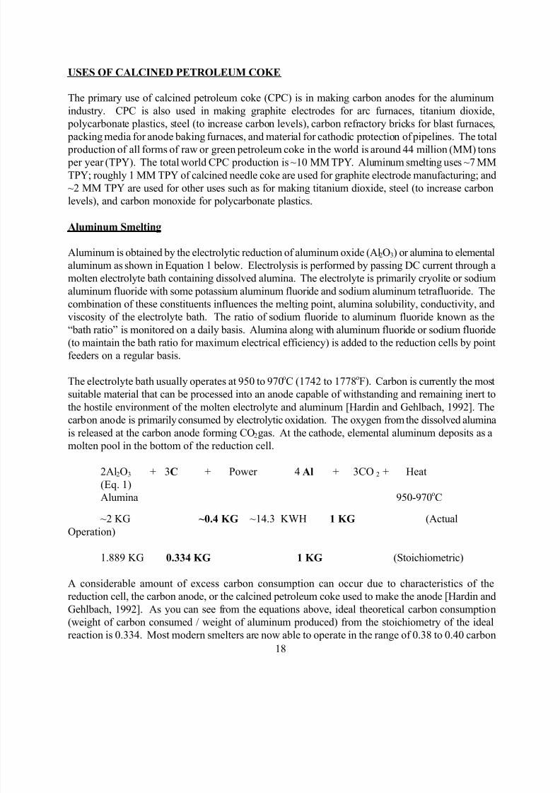
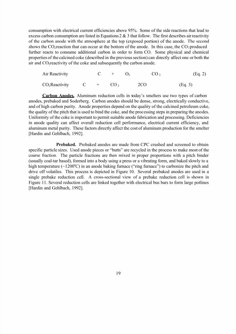
2Al2O3 + 3C + Power 4 Al + 3CO 2 + Heat
(Eq. 1)
Alumina 950-970oC
~2 KG ~0.4 KG ~14.3 KWH 1 KG (Actual
Operation)
1.889 KG 0.334 KG 1 KG (Stoichiometric)
A considerable amount of excess carbon consumption can occur due to characteristics of the
reduction cell, the carbon anode, or the calcined petroleum coke used to make the anode [Hardin and
Gehlbach, 1992]. As you can see from the equations above, ideal theoretical carbon consumption
(weight of carbon consumed / weight of aluminum produced) from the stoichiometry of the ideal
reaction is 0.334. Most modern smelters are now able to operate in the range of 0.38 to 0.40 carbon
consumption with electrical current efficiencies above 95%. Some of the side reactions that lead to
excess carbon consumption are listed in Equations 2 & 3 that follow. The first describes air reactivity
of the carbon anode with the atmosphere at the top (exposed portion) of the anode. The second
shows the CO2 reaction that can occur at the bottom of the anode. In this case, the CO 2 produced
further reacts to consume additional carbon in order to form CO. Some physical and chemical
properties of the calcined coke (described in the previous section) can directly affect one or both theair and CO2 reactivity of the coke and subsequently the carbon anode.
Air Reactivity C + O2 CO 2 (Eq. 2)
CO2 Reactivity C + CO 2 2CO (Eq. 3)
Carbon Anodes. Aluminum reduction cells in today’s smelters use two types of carbon
anodes, prebaked and Soderberg. Carbon anodes should be dense, strong, electrically conductive,
and of high carbon purity. Anode properties depend on the quality of the calcined petroleum coke,
the quality of the pitch that is used to bind the coke, and the processing steps in preparing the anodes.
Uniformity of the coke is important to permit suitable anode fabrication and processing. Deficienciesin anode quality can affect overall reduction cell performance, electrical current efficiency, and
aluminum metal purity. These factors directly affect the cost of aluminum production for the smelter
[Hardin and Gehlbach, 1992].
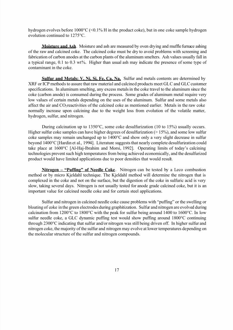
Prebaked. Prebaked anodes are made from CPC crushed and screened to obtain
specific particle sizes. Used anode pieces or “butts” are recycled in the process to make most of the
coarse fraction. The particle fractions are then mixed in proper proportions with a pitch binder
(usually coal-tar based), formed into a body using a press or a vibrating form, and baked slowly to a
high temperature (~1200oC) in an anode baking furnace (“ring furnace”) to carbonize the pitch and
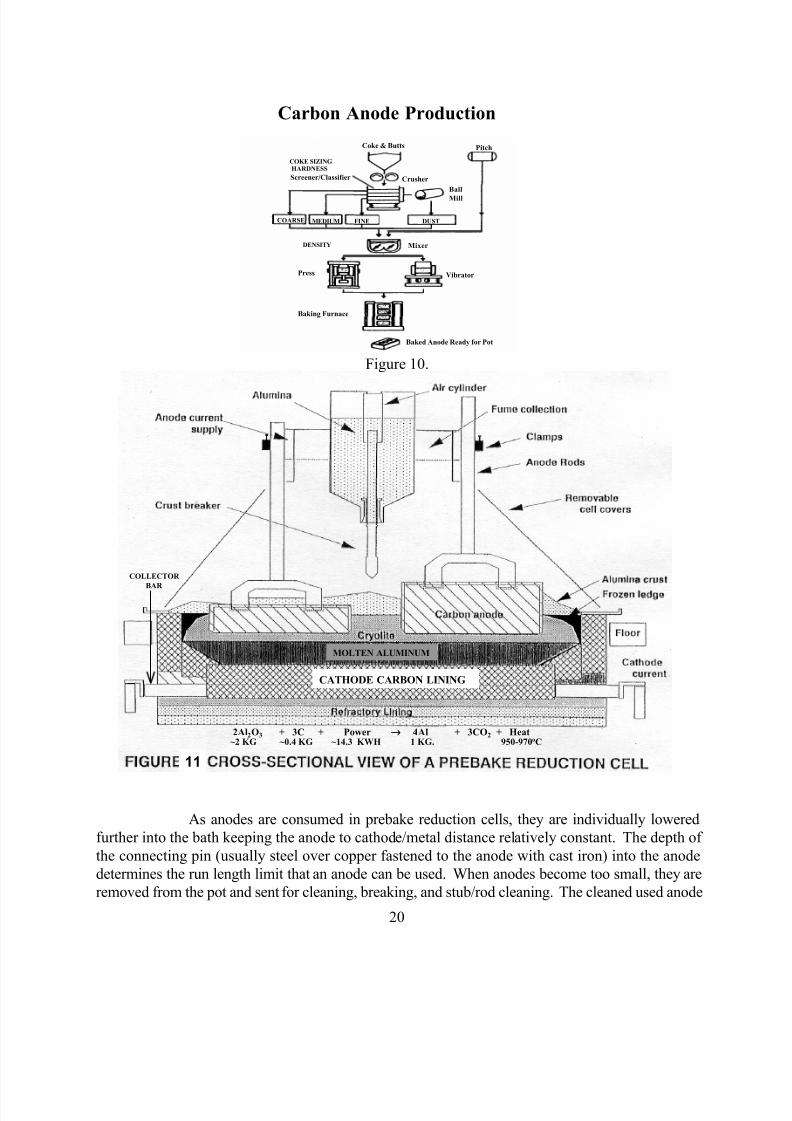
drive off volatiles. This process is depicted in Figure 10. Several prebaked anodes are used in a
single prebake reduction cell. A cross-sectional view of a prebake reduction cell is shown inFigure 11. Several reduction cells are linked together with electrical bus bars to form large potlines
pieces or “butts” are then re-used as a coarse component of the green anode mix. The rods/stubs are
also cleaned and returned to be rejoined with newly baked anodes ready for service. If an anode is
used too long, the connecting pin may become exposed in the bath, and the pin materials (mostly iron
and copper) could contaminate the aluminum.
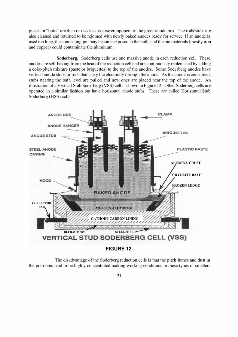
Soderberg. Soderberg cells use one massive anode in each reduction cell. Theseanodes are self-baking from the heat of the reduction cell and are continuously replenished by adding
a coke-pitch mixture (paste or briquettes) to the top of the anodes. Some Soderberg anodes have
vertical anode stubs or rods that carry the electricity through the anode. As the anode is consumed,
stubs nearing the bath level are pulled and new ones are placed near the top of the anode. An
illustration of a Vertical Stub Soderberg (VSS) cell is shown in Figure 12. Other Soderberg cells are
operated in a similar fashion but have horizontal anode stubs. These are called Horizontal Stub
Soderberg (HSS) cells.
ALUMINA CRUST
CRYOLITE BATH
FROZEN LEDGE
MOLTEN ALUMINUM
CATHODE CARBON LINING
REFRACTORY STEEL SHELL
COLLECTOR
BAR
FIGURE 12.
The disadvantage of the Soderberg reduction cells is that the pitch fumes and dust in
the potrooms tend to be highly concentrated making working conditions in these types of smelters
Needle Coke / Special Coking. Anisotropic (needle) coke is required for graphite electrode
manufacturing. Needle coke is formed from the mesophase or liquid crystalline type coke. Coking
of needle coke is similar to growing crystals in that the lower the temperature, the larger the needles
and the lower the CTE. A special coker feedstock high in aromatic hydrocarbons, decant oil fromthe bottoms of fluid catalytic cracking product, is normally de-ashed using special chemicals to
enhance the settling of the catalyst fines or by filtering the decant oil through a series of catalyst
filters. The decant oil is then usually hydrodesulfurized to less than 0.7% sulfur in order to meet the
sulfur specifications required in the green needle coke. Higher than typical coking temperatures,
pressure, and recycle rates are used to produce a maximum amount of needle coke that is very low in
volatile matter.
Needle Coke / Special Calcining. It is difficult to calcine needle coke to obtain the best
properties. The coke mesophase has a tendency to revert to a liquid during rapid heating. When the
volatile matter starts to evolve during calcination, bloating of the structure occurs leaving a low-
density coke with a higher CTE. Volatile matter in the coke can also cause some of the particles tofuse together which also causes the CTE to increase. Some needle coke producers partially
devolatilize (preheat) the coke before calcining to prevent bloating and to keep a low CTE. Graphite
electrode manufacturers now demand that the needle coke CTE be below 2 x 10⁻⁷
cm/cm/oC.
The usual specification on RD for needle coke is 2.13 g/cc. Rotary kiln calciners are normally
used to calcine needle coke because rotary hearths tend to produce too many fines (minus 1 mm)
during calcination. In calcined needle coke, coarse particles (+6 mm) are desired. Greater than 0.78
g/cc 4 to 6 mesh bulk density is also required. Low ash content, < 0.3 wt% ash, is required since any
ash would leave a void in the structure when graphitized. Even with all the property specifications, an
electrode manufacturer will not accept calcined needle coke for production until they have actually
run a trial lot through the plant and trials on an electric arc furnace. Obtaining good needle coke isstill a “black art” for excellent graphite electrodes [Ellis and Paul, 1998].
Use of Graphite Electrodes – Arc Furnace Steel Production. The most popular electrode
is the 24 inch (60 cm), with a demand for larger than 30 inch (76 cm) for single electrode DC
furnaces. The principal property that an electric arc furnace steel mill wants in graphite electrodes is
low graphite use (electrode consumption) per ton of steel produced. In single electrode DC furnaces,
graphite use per ton of steel is below 2 kg. With better practices and use of foamy slag, AC furnaces(using three electrodes due to three-phase electric power) have approached this level [Ellis and Paul,
1998].
Specialty Graphite Industry
Graphite Moldstocks. Very large pieces of graphite are used for casting large items such as
(steel) railcar wheels. To make the graphite, very fine-grained calcined coke with high density and
high CTE is needed. Calcined isotropic (shot or near-shot type) coke is preferred. The molds are
usually used upside down with the molten steel flowing up into the molds.
Semi-Graphite Electrodes. Semi-graphite electrodes are produced from calcined spongecoke for specialty electric furnace uses such as in manufacturing phosphorus or titanium dioxide
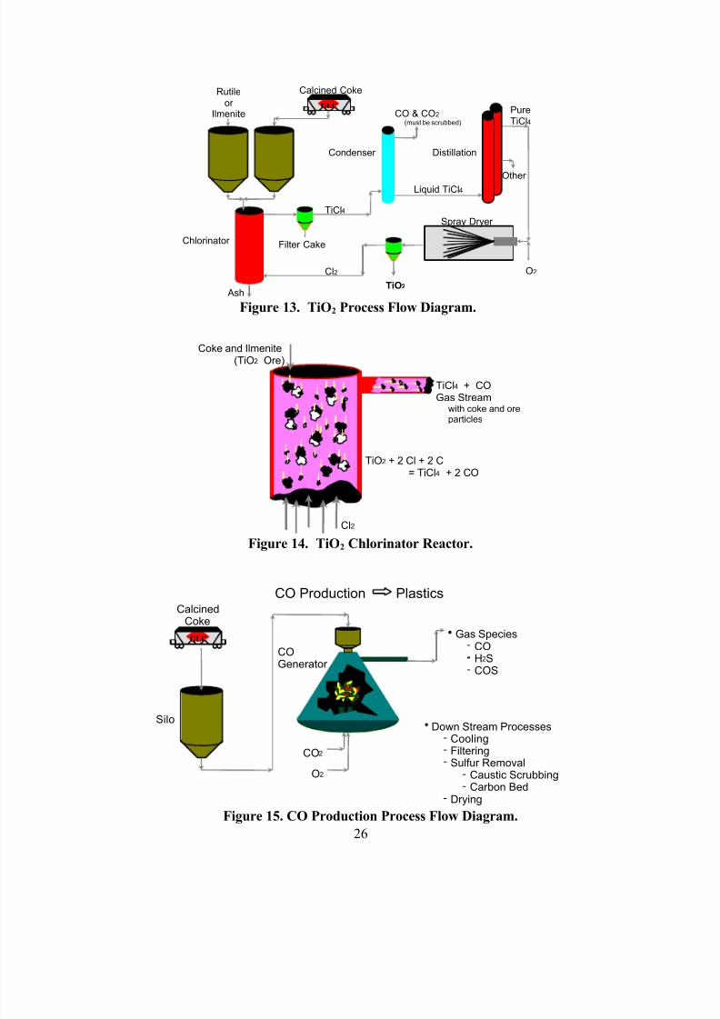
Calcined petroleum coke is used in the production of titanium dioxide (in the chloride process). A
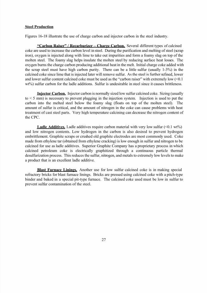
flow diagram of the titanium dioxide chloride process is shown in Figure 13. The calcined coke must
be sized (usually to < 5 mm) for use in the fluidized chlorinator reactor (see Figure 14) where the
coke reduces the titanium dioxide from the ore (forming CO and CO2) and furnishes heat for thechlorination of the titanium to titanium tetrachloride. Further processing by oxidizing the titanium
tetrachloride results in pure titanium dioxide product in a powdered form. Chlorine is recycled and
returned to the chlorinator. Finished titanium dioxide is commonly used as a brilliant white pigment
for paint, paper, plastics, ceramics, textiles, rubber, and inks, and is also used in pharmaceuticals
[Pace Consultants 1990].
For this application, low moisture (<0.3%), low hydrogen (<0.2%), hard calcined coke is desired with
a minimum amount of fines (usually < 5% minus 60 mesh). Any moisture or hydrogen would form
hydrochloric acid in the chlorinator, and coke fines have a tendency to be blown out of the process.
The metals in the coke are not as critical as in aluminum anodes, but low ash is desired since it
becomes a waste removal problem forming slag in the chlorinator. Although typical sulfur valuesusually vary from 2.5-3.5 wt%, some customers prefer lower sulfur coke due to environmental
emission limitations.
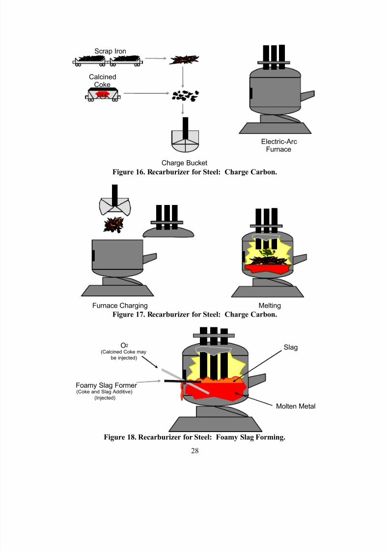
Chemical Processing: Carbon Monoxide for Polycarbonate Plastics Production
Sized calcined petroleum coke with low hydrogen content is used in a gasification process (in
Stauffer-type CO Generators) to make carbon monoxide. A simplified process flow is presented in
Figure 15. Further synthesis produces phosgene gas used for the production of high strength
polycarbonate plastics. Low hydrogen is needed to prevent the formation of hydrochloric acid during
the chlorinating of the carbon monoxide. Sizing is critical in some applications to transport the coke
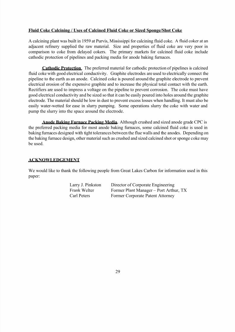
Figures 16-18 illustrate the use of charge carbon and injector carbon in the steel industry.
“Carbon Raiser” / Recarburizer – Charge Carbon. Several different types of calcined
coke are used to increase the carbon level in steel. During the purification and melting of steel (scrapiron), oxygen is injected along with lime to take out impurities and form a foamy slag on top of the
molten steel. The foamy slag helps insulate the molten steel by reducing surface heat losses. The
oxygen burns the charge carbon producing additional heat in the melt. Initial charge coke added with
the scrap steel must have high carbon purity. There can be a little sulfur (usually 1-3%) in the
calcined coke since lime that is injected later will remove sulfur. As the steel is further refined, lower
and lower sulfur content calcined coke must be used as the “carbon raiser” with extremely low (<0.1
wt%) sulfur carbon for the ladle additions. Sulfur is undesirable in steel since it causes brittleness.
to < 5 mm) is necessary to prevent plugging in the injection system. Injection is used to put the
carbon into the melted steel below the foamy slag (floats on top of the molten steel). Theamount of sulfur is critical, and the amount of nitrogen in the coke can cause problems with heat
treatment of cast steel parts. Very high temperature calcining can decrease the nitrogen content of
the CPC.
Ladle Additives. Ladle additives require carbon material with very low sulfur (<0.1 wt%)
and low nitrogen contents. Low hydrogen in the carbon is also desired to prevent hydrogen
embrittlement. Graphite scraps or crushed old graphite electrodes are most commonly used. Coke
made from ethylene tar (obtained from ethylene cracking) is low enough in sulfur and nitrogen to be
calcined for use as ladle additives. Superior Graphite Company has a proprietary process in which
calcined petroleum coke is electrically graphitized through a continuous particle thermal
desulfurization process. This reduces the sulfur, nitrogen, and metals to extremely low levels to makea product that is an excellent ladle additive.
Blast Furnace Linings. Another use for low sulfur calcined coke is in making special
refractory bricks for blast furnace linings. Bricks are pressed using calcined coke with a pitch-type
binder and baked in a special pit-type furnace. The calcined coke used must be low in sulfur to