24
OPERATION MANUAL TWE-375 CAPACITOR DISCHARGE WELDER TRU‐WELD EQUIPMENT COMPANY 6400 N. HONEYTOWN ROAD SMITHVILLE, OHIO 44677 (330) 725‐7744 [email protected] Version 1.0 Date 8/13/2013
| Date post: | 15-Mar-2018 |
| Category: |
Documents |
| Upload: | truongkhue |
| View: | 217 times |
| Download: | 3 times |

OPERATION MANUAL
TWE-375 CAPACITOR DISCHARGE
WELDER
TRU‐WELD EQUIPMENT COMPANY 6400 N. HONEYTOWN ROAD SMITHVILLE, OHIO 44677 (330) 725‐7744 [email protected]
Version 1.0 Date 8/13/2013

2
TRU‐WELD EQUIPMENT LIMITED WARRANTY
All goods produced by Truweld Equipment shall be warranted against defects including workmanship and components. No other war‐ranties whether expressed, verbal, or implied will apply. Warranties only apply to the original equipment purchaser.
Warranty claims will be limited to either repair or replacement of the defective materials by Truweld Equipment. At the option of Tru‐weld Equipment the location of where the warranty evaluation and repairs are made will be determined. All warranty claim items re‐turned to Truweld Equipment will be at the customer’s expense. At the option of Truweld Equipment the defect will either be repaired or replaced. Notice must be provided to Truweld Equipment of a warranty defect within 30 days that the defect or failure is incurred. Warranties are not transferable.
This warranty does not apply for equipment which is used improperly in any fashion including but not exclusive to the following:
Equipment which has been modified
Equipment which has not been installed properly
Equipment which has been used for purposes other than which it had been designed
Equipment which has not been properly maintained
Equipment which was continued to be used after a defect had been found
Equipment which was damaged in any way
Truweld Equipment will never be liable for consequential damages, loss, or expense occurring directly or indirectly from the use of the equipment covered in this warranty.
All cables, cable sets and connectors are not warranted.
Two (2) year warranty period from date of purchase
SC3402 Power Supply SC3400 Power Supply
SC2420 Power Supply SC2402 Power Supply
SC2400 Power Supply SC1900 Power Supply
SC1950 Power Supply SC1600 Power Supply
SC1650 Power Supply SC1400 Power Supply
SC1450 Power Supply SC900 Power Supply
TWE250 Power Supply
TWE321 Power Supply
TWE375 Power Supply
One (1) year warranty period from date of purchase
TWESPC Power Supplies
TWP‐2 Power Supply
Ninety Day warranty period from date of purchase
(Excluding cables and connectors)
TWE70000 HD Arc stud gun
TWE18500 MD Arc stud gun
TWE19000 LD Arc stud gun
TWEG CD stud gun
TWEHDG Heavy Duty CD stud gun
3
CONTENTS
Section Description Pages
1 Warranty 2
2 Table of Contents 3
4 Introduction 5
5 External Features 6‐7
6 Safety 8‐10
7 Setup And Welding 11‐17
8 Testing Weld Settings 18‐19
9 Internal Components 20‐22
10 CD Stud Gun Exploded View 23
3 Product Specs and Features 4
4
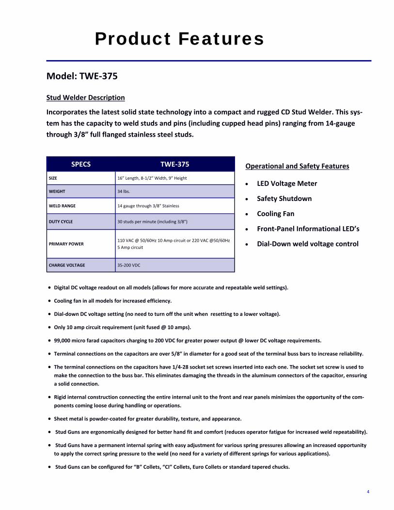
Product Features
Incorporates the latest solid state technology into a compact and rugged CD Stud Welder. This sys‐tem has the capacity to weld studs and pins (including cupped head pins) ranging from 14‐gauge through 3/8” full flanged stainless steel studs.
Stud Welder Description
Model: TWE‐375
Operational and Safety Features
• LED Voltage Meter
• Safety Shutdown
• Cooling Fan
• Front‐Panel Informational LED’s
• Dial‐Down weld voltage control
• Digital DC voltage readout on all models (allows for more accurate and repeatable weld settings).
• Cooling fan in all models for increased efficiency.
• Dial‐down DC voltage setting (no need to turn off the unit when resetting to a lower voltage).
• Only 10 amp circuit requirement (unit fused @ 10 amps).
• 99,000 micro farad capacitors charging to 200 VDC for greater power output @ lower DC voltage requirements.
• Terminal connections on the capacitors are over 5/8” in diameter for a good seat of the terminal buss bars to increase reliability.
• The terminal connections on the capacitors have 1/4‐28 socket set screws inserted into each one. The socket set screw is used to make the connection to the buss bar. This eliminates damaging the threads in the aluminum connectors of the capacitor, ensuring a solid connection.
• Rigid internal construction connecting the entire internal unit to the front and rear panels minimizes the opportunity of the com‐ponents coming loose during handling or operations.
• Sheet metal is powder‐coated for greater durability, texture, and appearance.
• Stud Guns are ergonomically designed for better hand fit and comfort (reduces operator fatigue for increased weld repeatability).
• Stud Guns have a permanent internal spring with easy adjustment for various spring pressures allowing an increased opportunity to apply the correct spring pressure to the weld (no need for a variety of different springs for various applications).
• Stud Guns can be configured for “B” Collets, “CI” Collets, Euro Collets or standard tapered chucks.
SPECS TWE‐375
SIZE 16” Length, 8‐1/2” Width, 9” Height
WEIGHT 34 lbs.
WELD RANGE 14 gauge through 3/8” Stainless
DUTY CYCLE 30 studs per minute (including 3/8”)
PRIMARY POWER 110 VAC @ 50/60Hz 10 Amp circuit or 220 VAC @50/60Hz 5 Amp circuit
CHARGE VOLTAGE 35‐200 VDC
5
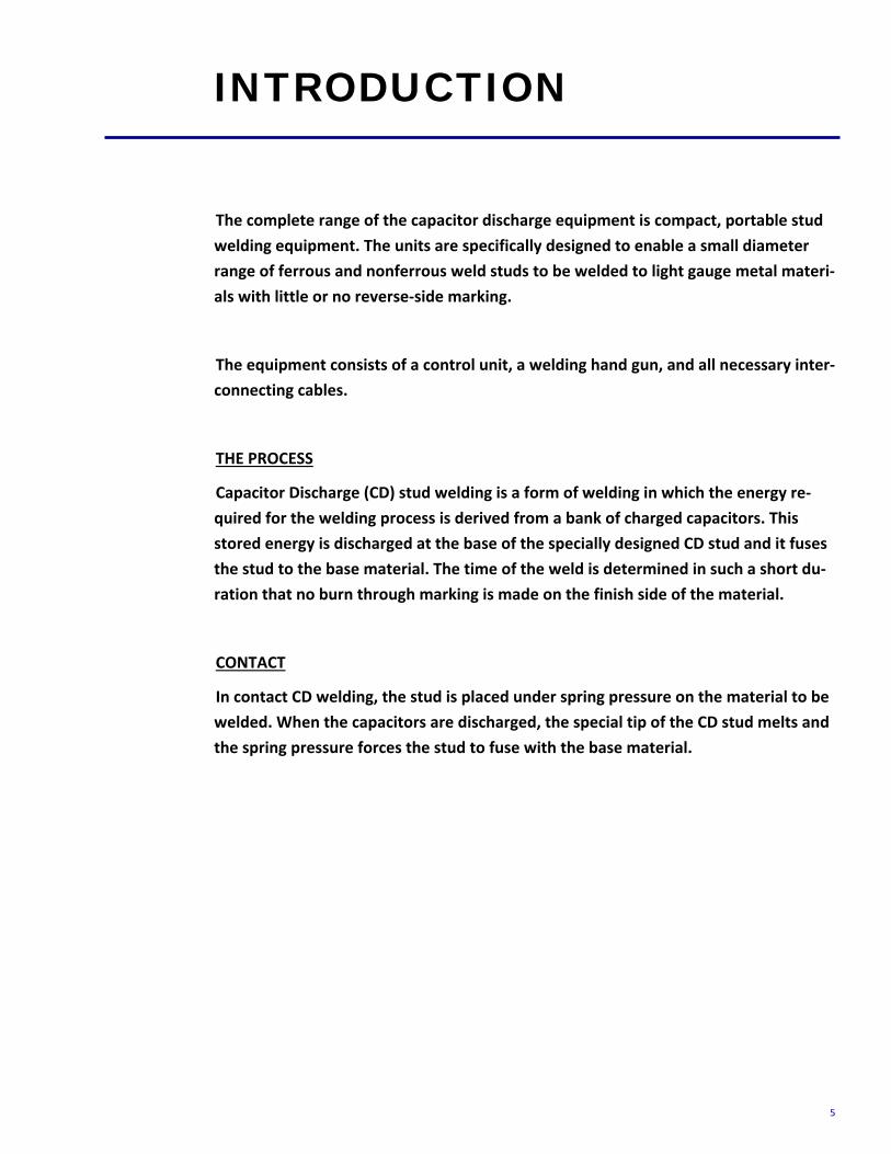
The complete range of the capacitor discharge equipment is compact, portable stud welding equipment. The units are specifically designed to enable a small diameter range of ferrous and nonferrous weld studs to be welded to light gauge metal materi‐als with little or no reverse‐side marking.
The equipment consists of a control unit, a welding hand gun, and all necessary inter‐connecting cables.
THE PROCESS
Capacitor Discharge (CD) stud welding is a form of welding in which the energy re‐quired for the welding process is derived from a bank of charged capacitors. This stored energy is discharged at the base of the specially designed CD stud and it fuses the stud to the base material. The time of the weld is determined in such a short du‐ration that no burn through marking is made on the finish side of the material.
CONTACT
In contact CD welding, the stud is placed under spring pressure on the material to be welded. When the capacitors are discharged, the special tip of the CD stud melts and the spring pressure forces the stud to fuse with the base material.
INTRODUCTION
6
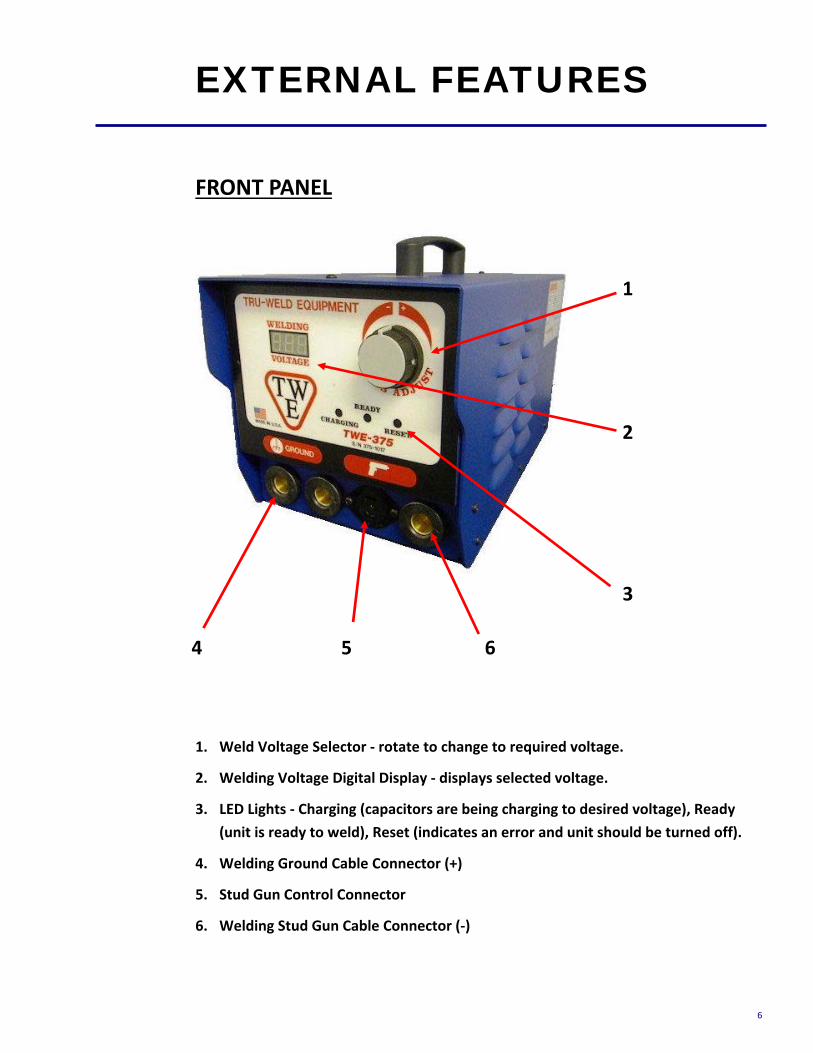
FRONT PANEL
1. Weld Voltage Selector ‐ rotate to change to required voltage.
2. Welding Voltage Digital Display ‐ displays selected voltage.
3. LED Lights ‐ Charging (capacitors are being charging to desired voltage), Ready (unit is ready to weld), Reset (indicates an error and unit should be turned off).
4. Welding Ground Cable Connector (+)
5. Stud Gun Control Connector
6. Welding Stud Gun Cable Connector (‐)
EXTERNAL FEATURES
1
4
2
5 6
3

7
REAR PANEL 1.On/Off Switch
2.Circuit Breaker
3.AC Power Cord
4.Manufacturer Model Number and Serial Number Plate
WARNING! This unit operates from a 110 VAC 60 Hertz @10 amp circuit
or 220 VAC 50 Hertz @ 5 amp circuit.
Do not obstruct the ventilation fan, as this may cause unit to over heat.
Do not remove any portion of the unit housing without first disconnecting the unit from the power supply.
EXTERNAL FEATURES
ON/OFF Switch
15Amp Circuit Breaker
Power Supply Fan
AC Cord

8
PROTECT YOURSELF AND OTHERS! Read the safety notices before using welder.
ELECTRICAL No portion of the outer cover of the welding controller should be removed by any‐one other than qualified personnel. Always disconnect the unit from the main power prior to removing cover.
• This equipment contains a transformer power supply system, which is energized by AC current and transforms the AC to DC current. Due to potential dangerous electrical input and output the equipment must be disconnected from all incom‐ing power when servicing.
• Capacitors store electrical energy. Check for residual charge before performing any maintenance.
• Do not use fluids to clean electrical components as these may penetrate the elec‐trical system and cause shorts.
Connection of the unit into service must be in accordance with the setup procedures as detailed in this manual. Operation of this equipment must be in accordance with all local, regional, and national safety codes.
SAFETY
9
FIRE During welding, small particles of hot metal can be expelled. Ensure that no combus‐tible materials are near the welding area.
PERSONAL SAFETY Arc rays can burn your eyes and skin. Wear protective clothing and eye protection when welding.
Loud noises from welding can damage hearing. Wear earplugs or other protective gear, if applicable.
Fumes and gases expelled during welding can be hazardous to your health. Make sure welding is done in a well‐ventilated area.
Hot metal splatter can cause fires and burns. Wear protective clothing, free of com‐bustible materials. Have a fire extinguisher nearby and know how to use it.
MAINTENANCE All cables must be inspected regularly to ensure that no danger exists from worn or damaged insulation or unsafe electrical connections. Take special note to the cables near the stud gun ‐ this is where maximum wear occurs.
Worn cables not only produce inconsistent welds, but can overheat or spark.
SAFETY
FIRE HAZARD FROM SPARKS

10
TRAINING Use of this equipment must be limited to authorized personnel only. They must be adequately trained, and have read and understood everything in this manual. The manual must be available to operators at all times.
INSTALLATION Select a site for the equipment which is capable of supporting the weight of the equipment, which is clear from traffic routes where people may trip over cables, or they may be damaged by other equipment or vehicles.
Do not hang connecting cables over sharp edges or have near heat sources.
DISPOSAL The equipment, in its entirety or as components/parts may be disposed of as general industrial waste or scrap. None of the components used in the manufacturing of the CD Welders are toxic, carcinogenic, or otherwise harmful to your health.
SAFETY
AUTHORIZED PERSONNEL ONLY

11
POWERING UP THE EQUIPMENT Setup the equipment power supply (Control Unit) and connect to the main power, making certain of the proper voltage requirement of the particular unit.
Capacitor Discharge (CD) units generally require 110 VAC @ 60Hz incoming power. Refer to the safety recommendations before plugging this unit in.
ON/OFF Switch
Circuit Breaker
Power Cord (110 VAC)
CONNECTING THE WELDING LEADS Connect the welding ground cable into the (+) terminal mount socket on the front of the welding unit.
***NOTE ‐ the cable end plug has a flat which aligns with a dot on the panel mount socket. Secure the connector into the panel mount socket, and then turn it clockwise until it locks into proper position. Failure to do so could result in damage to the con‐nector.
Ground Cable Socket
SET-UP AND WELDING
12
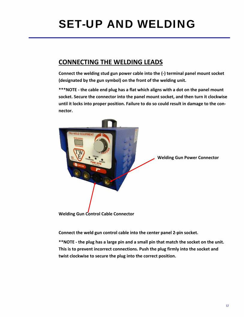
CONNECTING THE WELDING LEADS Connect the welding stud gun power cable into the (‐) terminal panel mount socket (designated by the gun symbol) on the front of the welding unit.
***NOTE ‐ the cable end plug has a flat which aligns with a dot on the panel mount socket. Secure the connector into the panel mount socket, and then turn it clockwise until it locks into proper position. Failure to do so could result in damage to the con‐nector.
Welding Gun Power Connector
Welding Gun Control Cable Connector
Connect the weld gun control cable into the center panel 2‐pin socket.
**NOTE ‐ the plug has a large pin and a small pin that match the socket on the unit. This is to prevent incorrect connections. Push the plug firmly into the socket and twist clockwise to secure the plug into the correct position.
SET-UP AND WELDING
13
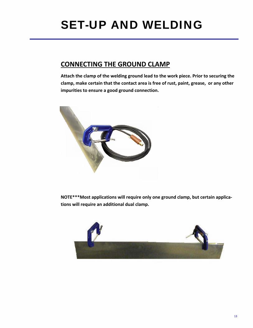
CONNECTING THE GROUND CLAMP Attach the clamp of the welding ground lead to the work piece. Prior to securing the clamp, make certain that the contact area is free of rust, paint, grease, or any other impurities to ensure a good ground connection.
NOTE***Most applications will require only one ground clamp, but certain applica‐tions will require an additional dual clamp.
SET-UP AND WELDING

14
SELECTING THE PROPER STUD COLLET (STUD HOLDER) The collet is selected to the proper diameter that you are welding.
There are three styles of collets;
• The “B” collet which is a two‐piece assembly (collet and insert). The insert deter‐mines how much of the stud is engaged in the collet.
• The CI (Collet Insert) which is a single part and the amount of the stud that is en‐gaged is predetermined.
• Standard Adjustable Chucks have an adjustable internal screw to manually adjust for the engagement of the stud.
The choice between these systems is usually a matter of personal preference.
Inserting the selected collet into the stud gun is a simple task. Place the collet into the front holder of the stud gun and set the locking screws to hold it in place.
After inserting the collet, mount the two legs and foot piece onto the stud gun. The collet should be centered through the opening of the foot piece.
When the legs and foot piece are in place, insert the stud to be welded into the col‐let. Adjust the leg and foot piece by sliding it into position until approximately 1/8” of the stud protrudes from beyond the foot piece. Lock legs in place with the set screws.
SET-UP AND WELDING
Foot Piece
Collet
Leg Piece
15
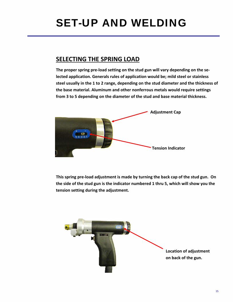
SELECTING THE SPRING LOAD The proper spring pre‐load setting on the stud gun will vary depending on the se‐lected application. Generals rules of application would be; mild steel or stainless steel usually in the 1 to 2 range, depending on the stud diameter and the thickness of the base material. Aluminum and other nonferrous metals would require settings from 3 to 5 depending on the diameter of the stud and base material thickness.
This spring pre‐load adjustment is made by turning the back cap of the stud gun. On the side of the stud gun is the indicator numbered 1 thru 5, which will show you the tension setting during the adjustment.
SET-UP AND WELDING
Adjustment Cap
Tension Indicator
Location of adjustment on back of the gun.

16
READY FOR WELDING When you have completed all of the previous steps to prepare for welding, including connecting the stud gun and ground cables to the unit, attaching the ground cable(s) to the work area, setting up and adjusting the stud gun for the selected stud diame‐ter and material, you can now power on the welder.
The controller ON/OFF switch is located on the rear of the unit in the upper right hand corner. Below this switch is the 15amp fuse holder for the system.
SET-UP AND WELDING
ON/OFF SWITCH
Circuit Breaker

17
VOLTAGE SELECTION Selecting the required weld voltage is achieved by turning the selector knob. The voltage range is from 35VDC to 200VDC.
The voltage is determined by the diameter of the stud and the base material.
Approximate voltage staring points are listed below. Fine tuning the voltage to meet your requirement for your specific application is recommended.
NOTE***when welding cupped‐head insulation pins, set the DC Voltage between 65 and 70 VDC to begin and increase as necessary. Adjust the spring pressure on the CD gun between #1 and #3 as necessary.
SET-UP AND WELDING
Diameter Voltage (DC)
14 ga. 50‐75
12 ga. 75‐110
#8 110‐130
#10 125‐160
1/4” 160‐190
MODEL TWE‐250 Diameter Voltage (DC)
14 ga. 35‐50
12 ga. 50‐75
#8 75‐100
#10 100‐120
1/4” 120‐140
MODEL TWE‐375 & 375
3/8” (TWE‐375) 160‐200
5/16” 140‐160
Voltage Adjustment Knob

18
TESTING YOUR SETTINGS When you have performed all of the presets as discussed in this manual, it is recom‐mended that you perform several test welds with the same diameter stud and base material that you will be using. This will verify that all of the settings are correct to the results you desire. Welding is done by placing the stud into the collet, and press‐ing the stud gun to the work piece, compressing the spring. This is why the stud must protrude beyond the foot piece at least 1/8”.
Holding the gun perpendicular to the work piece, and aligning the stud to the desired position on the work piece, press down so that the foot piece is flush with the work piece (spring compressed), and depress the trigger.
When removing the stud gun from the welded stud, always lift the stud gun vertically from the welded stud in order to maintain the proper tension of the collet. Spreading the collet when lifting the stud gun from the welded stud will shorten the life of the collet and will eventually create an undesirable weld.
TESTING WELD SETTINGS
19
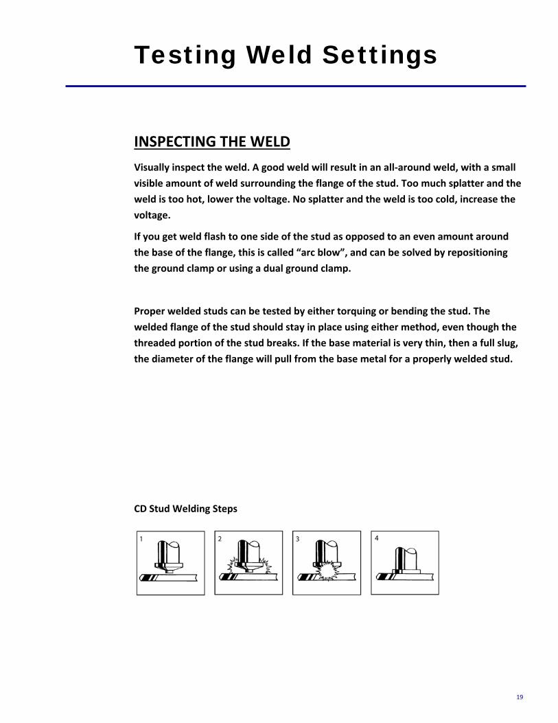
INSPECTING THE WELD Visually inspect the weld. A good weld will result in an all‐around weld, with a small visible amount of weld surrounding the flange of the stud. Too much splatter and the weld is too hot, lower the voltage. No splatter and the weld is too cold, increase the voltage.
If you get weld flash to one side of the stud as opposed to an even amount around the base of the flange, this is called “arc blow”, and can be solved by repositioning the ground clamp or using a dual ground clamp.
Proper welded studs can be tested by either torquing or bending the stud. The welded flange of the stud should stay in place using either method, even though the threaded portion of the stud breaks. If the base material is very thin, then a full slug, the diameter of the flange will pull from the base metal for a properly welded stud.
CD Stud Welding Steps
Testing Weld Settings
20
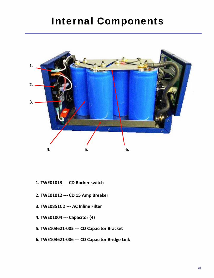
Internal Components
1.
2.
1. TWE01013 ‐‐‐ CD Rocker switch
6. 5. 4.
3.
2. TWE01012 ‐‐‐ CD 15 Amp Breaker
3. TWE0851CD ‐‐‐ AC Inline Filter
4. TWE01004 ‐‐‐ Capacitor (4)
5. TWE103621‐005 ‐‐‐ CD Capacitor Bracket
6. TWE103621‐006 ‐‐‐ CD Capacitor Bridge Link

21
Internal Components
1. 2.
1. TWE01001 ‐‐‐ PC Board
6. 5. 4. 3.
2. TWE01002/TWE01003 ‐‐‐ CD Thyristor /Clamp
3. TWE01011‐‐‐ CD Flyback Diode
4. TWE01010 ‐‐‐ CD TRIAC
5. TWE01009 ‐‐‐ CD Bridge Rectifier
6. TWE01015 ‐‐‐ CD Fan
7. 8. 10. 11.
7. TWE01019 ‐‐‐ CD Terminal Block
8. TWE01006 ‐‐‐ Main Wire Harness
9. TWE01014 ‐‐‐ Power Relay
10. TWE01005 ‐‐‐ CD Main Transformer
10. TWE01008 ‐‐‐ CD Power Resistor
9.
22
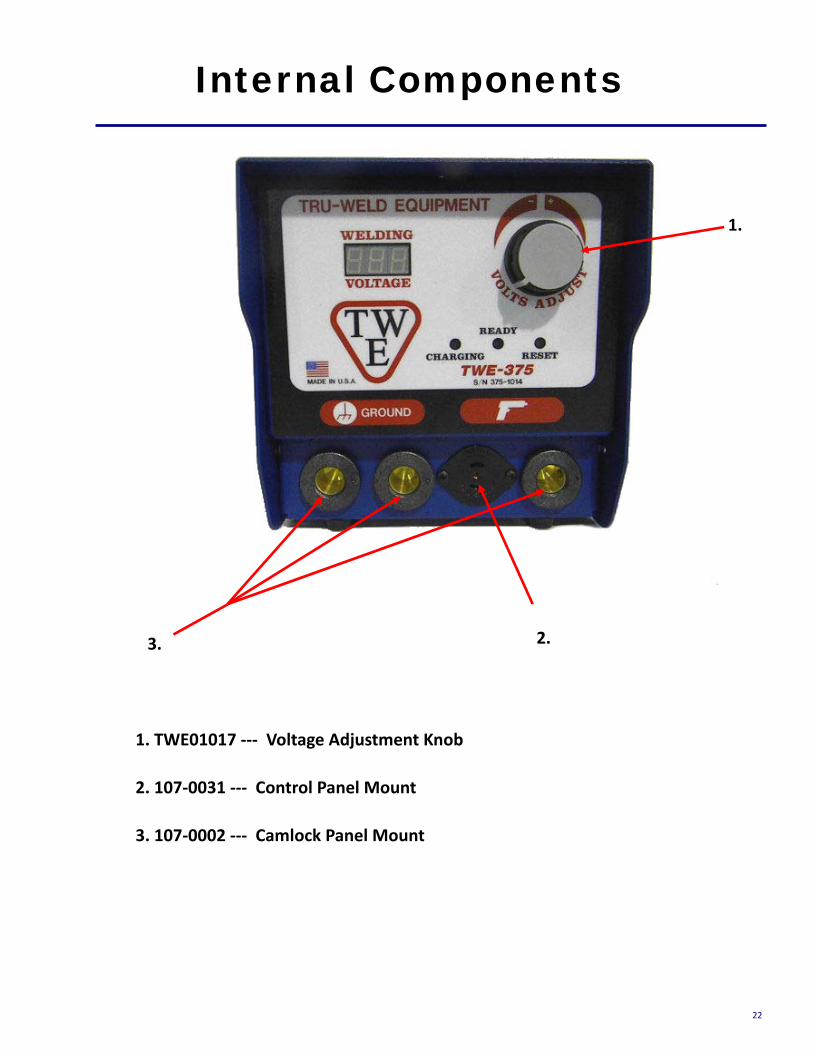
Internal Components
1. TWE01017 ‐‐‐ Voltage Adjustment Knob
2. 107‐0031 ‐‐‐ Control Panel Mount
3. 107‐0002 ‐‐‐ Camlock Panel Mount
1.
2. 3.

23
CD Gun Exploded View

24
TRU-WELD Equipment Company
6400 N. Honeytown Road
Smithville, Ohio 44677
(330) 725‐7744 Phone
(330) 669‐2473 Fax
http://truweldstudwelding.com


