Twisted Power Module – LM3886 (TPM-LM3886) A Twisted Pear Audio Production Russ White Overview: The TPM-LM3886 is a non-inverting (phase in = phase out) chip based power amplifier design utilizing National Semiconductor's LM3886 power operational amplifier. It is designed to work on its own or as a part of a larger system which we call “Twisted X Overture” or TXO for short. It is an extreme versatile amplifier, and can be tailored to suit a large array of projects. Chip amplifiers have been around for years, and in many ways are excellent amplifiers on their own. The LM3886 is extremely highly regarded and the basis for many hi-fi amplifiers. Many people will choose to build this module as a simple single ended amplifier, while others will be using it as part of a larger circuit call the “TXO”. The PCB layout is such that you have several building options. Dealing with DC on inputs: When using the TPM standalone, if you are going to be using a source with a DC component more then a few millivolts, then you should add an input coupling cap. For the 100K input impedance as designed 1uF is perfectly adequate, but you may prefer to go a little larger. You should only put the cap at the input of the TPM when the module is not used with a driver such as a TXD. If you are using the TXD (either for a TXO or a standard BPA) you would instead put the coupling caps on the inputs of the TXD, not the TPM. The coupling caps in any case would be mounted off the PCB. I usually mount them at or close to the input connectors. Dealing with DC offset: Every LM3886 has a certain amount of natural DC offset. That offset will change as the temperature of the chip changes. The DC offset at the output of the TPM will be the inherent offset multiplied by the gain of the TPM. DC offset has some side effects. It causes a constant load across both your amp (or amps in case of BA, PA, or BPA) and the load (speakers). It is possible that the DC could damage certain types of speakers. You will notice that the TPM has three ways to deal with the DC offset: 1) Do nothing. In many cases the DC offset is low enough (below 75mv is usually safe for conventional speakers) that nothing is really required. 2) Use the feedback cap (C6) which causes the TPM to pass DC at unity gain. So while this will reduce offset, some will still exist at the outputs. The drawback is that you now must have a relatively large capacitor in your feedback loop. That will have a performance impact, but by using a good low ESR cap you will still have an excellent amp. The LM3886 data sheet uses this approach in its example circuit. 3) Use the DC nulling servo marked by the blue area in the schematic in figure 1. The servo actively integrates a signal which is opposite in polarity to any DC which occurs on the TPM output. This type of circuit is know as an integrator or servo. It will reduce the DC offset to a very low value (usually < 5mv). If you want ultra low offset use the servo. Please notice, each of the methods above are mutually exclusive. You cannot for instance use the feedback capacitor(2) and the servo(3).
Transcript
Twisted Power Module – LM3886 (TPM-LM3886)A Twisted Pear Audio Production
Russ White
Overview:
The TPM-LM3886 is a non-inverting (phase in = phase out) chip based power amplifier design utilizing National Semiconductor's LM3886 power operational amplifier. It is designed to work on its own or as a part of a larger system which we call “Twisted X Overture” or TXO for short. It is an extreme versatile amplifier, and can be tailored to suit a large array of projects.
Chip amplifiers have been around for years, and in many ways are excellent amplifiers on their own. The LM3886 is extremely highly regarded and the basis for many hi-fi amplifiers. Many people will choose to build this module as a simple single ended amplifier, while others will be using it as part of a larger circuit call the “TXO”. The PCB layout is such that you have several building options.
Dealing with DC on inputs:
When using the TPM standalone, if you are going to be using a source with a DC component more then a few millivolts, then you should add an input coupling cap. For the 100K input impedance as designed 1uF is perfectly adequate, but you may prefer to go a little larger. You should only put the cap at the input of the TPM when the module is not used with a driver such as a TXD. If you are using the TXD (either for a TXO or a standard BPA) you would instead put the coupling caps on the inputs of the TXD, not the TPM. The coupling caps in any case would be mounted off the PCB. I usually mount them at or close to the input connectors.
Dealing with DC offset:
Every LM3886 has a certain amount of natural DC offset. That offset will change as the temperature of the chip changes. The DC offset at the output of the TPM will be the inherent offset multiplied by the gain of the TPM. DC offset has some side effects. It causes a constant load across both your amp (or amps in case of BA, PA, or BPA) and the load (speakers). It is possible that the DC could damage certain types of speakers. You will notice that the TPM has three ways to deal with the DC offset:
1) Do nothing. In many cases the DC offset is low enough (below 75mv is usually safe for conventional speakers) that nothing is really required.
2) Use the feedback cap (C6) which causes the TPM to pass DC at unity gain. So while this will reduce offset, some will still exist at the outputs. The drawback is that you now must have a relatively large capacitor in your feedback loop. That will have a performance impact, but by using a good low ESR cap you will still have an excellent amp. The LM3886 data sheet uses this approach in its example circuit.
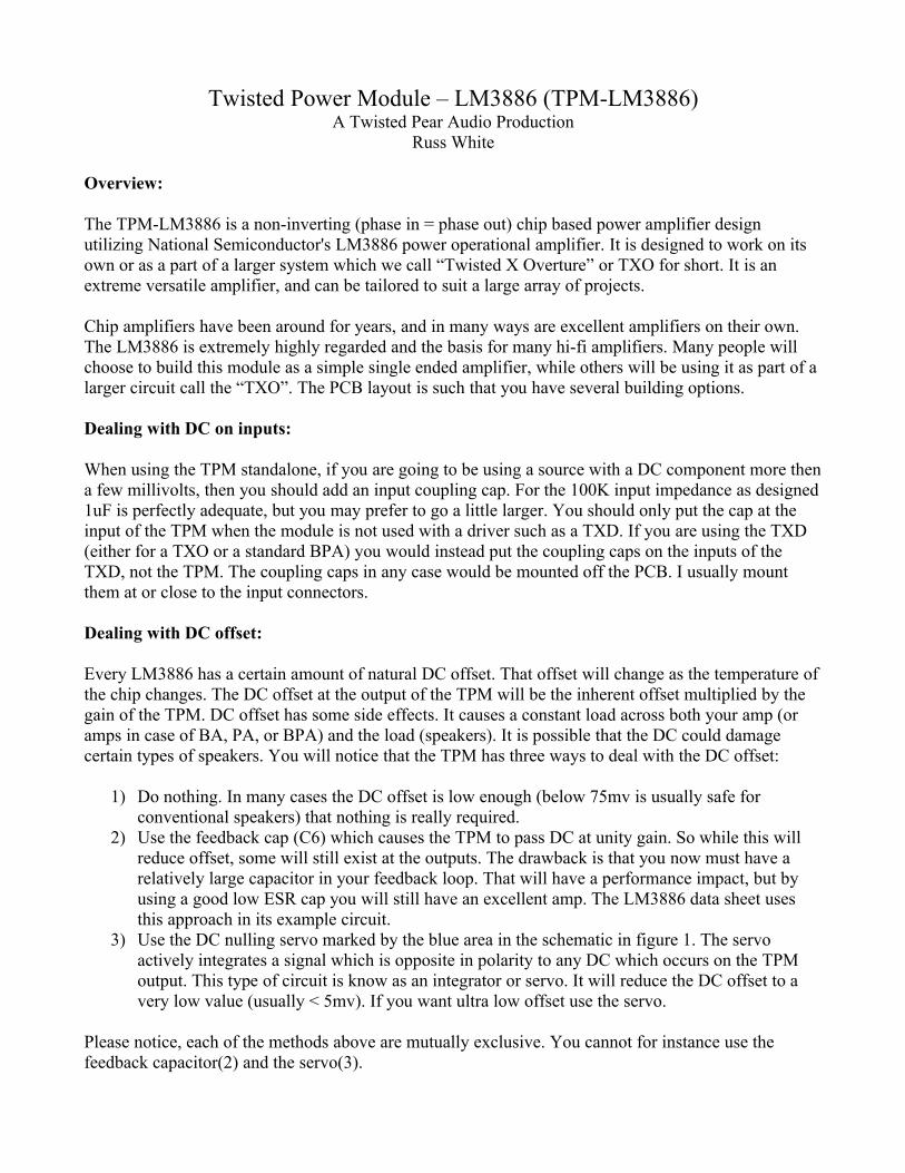
3) Use the DC nulling servo marked by the blue area in the schematic in figure 1. The servo actively integrates a signal which is opposite in polarity to any DC which occurs on the TPM output. This type of circuit is know as an integrator or servo. It will reduce the DC offset to a very low value (usually < 5mv). If you want ultra low offset use the servo.
Please notice, each of the methods above are mutually exclusive. You cannot for instance use the feedback capacitor(2) and the servo(3).
Figure 1: TPM-LM3886 schematic.
Minimum Components:
The minimum components to be used in the TPM are the components which are NOT shaded in the schematic. You can adjust the gain of the TPM by changing R1 and R2. See the data sheet of the LM3886 for more details there.
You can actually build a full TXO-2 with just the minimal components, but the TXO-4 always requires R7 and is safer with servo as well. In fact the minimalist approach with the fewest components in the signal path will be preferred by some. Performance is excellent in all configurations, so I would lean toward caution and suggest you use at least the servo.
Optional Components:DC Nulling Servo(Blue):
The components shaded blue are for the DC offset nulling servo. I recommend using the servo unless you have a good reason not to, especially anyone who wants low offset (some speakers demand extremely low offset). Low offset is also especially important for the parallel(PA) and bridged parallel (BPA) configurations. When in doubt use the servo.
Important, When using the servo you must omit C8.
LP(RF) Filter and Mute delay(Gold):
The components shaded gold should ONLY be used when the module will NOT be used inside the global feedback of a TXD, as is the case when building a TXO. So for the Twisted X Overture you would always omit the components shaded gold. C7 forms a low pass filter with R6 to help keep external high frequencies from entering the module. C8 is there to provide a short delay to the mute circuit at turn on.
Feedback capacitor and Zobel(Green):
The components shaded green are optional, C8 is used to reduce DC offset. It should be omitted when using the servo. If you wish to omit the servo but still find you have DC offset > 75mv or so you can use C8 to reduce the offset. I would suggest using the servo instead if possible. C5 and R5 are a Zobel network which can almost always be omitted. If you have an extremely inductive load you may find adding the Zobel helps. In most cases it actually increases distortion slightly, so I recommend omitting it unless you think you need it. It is relatively easy to add it later if you like.
Current Sensing Resistor(Red):
The red shaded resistor (R7) is a current sense resistor used in parallel applications. Either single ended (PA) or bridged (TXO-4/BPA) applications will require this resistor to ensure that paralleled power modules equally share the load. Without this resistor one module will drive nearly all the load and amplifier failure can soon occur. This resistor is only .1 ohm and actually can increase the stability of the amp even when not used in parallel configurations. I suggest you always use it.
Enjoy building these power modules. Take your time. Read up on any topic you don't understand. If you still have questions ask them before you flip on the power, by then it may be too late.
Designer's Recommendations:
Standalone basic single ended chip amp.
This is a good configuration for an nominal 8-ohm (even 4-ohm moderately driven) load.
– Use the current sense resistor (R7).– Use the servo– Omit the Zobel unless you suspect you will need it. It is easy to add later.– Use the mute cap(C8) as it will give you a bit longer turn on delay.– Use the low pass cap (C7) as it will help keep RF junk out of your amp.
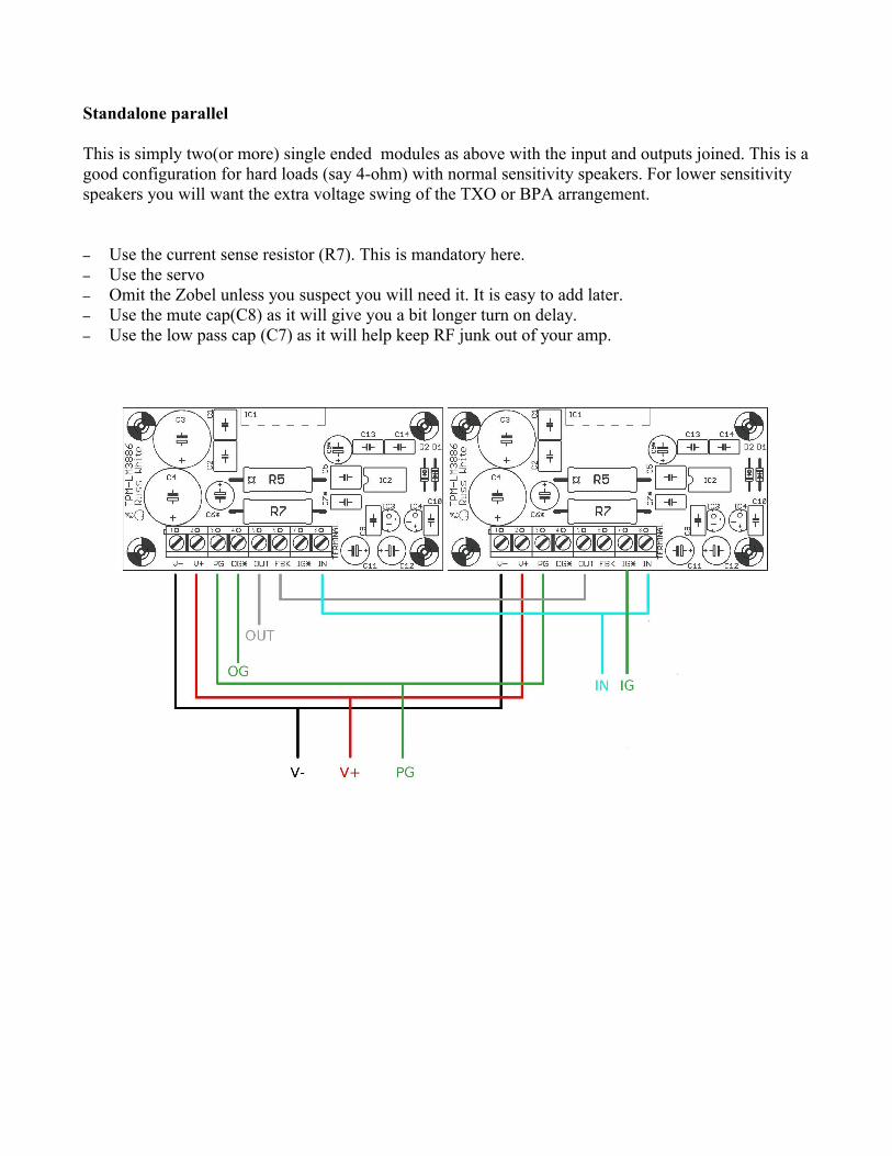
Standalone parallel
This is simply two(or more) single ended modules as above with the input and outputs joined. This is a good configuration for hard loads (say 4-ohm) with normal sensitivity speakers. For lower sensitivity speakers you will want the extra voltage swing of the TXO or BPA arrangement.
– Use the current sense resistor (R7). This is mandatory here.– Use the servo– Omit the Zobel unless you suspect you will need it. It is easy to add later.– Use the mute cap(C8) as it will give you a bit longer turn on delay.– Use the low pass cap (C7) as it will help keep RF junk out of your amp.
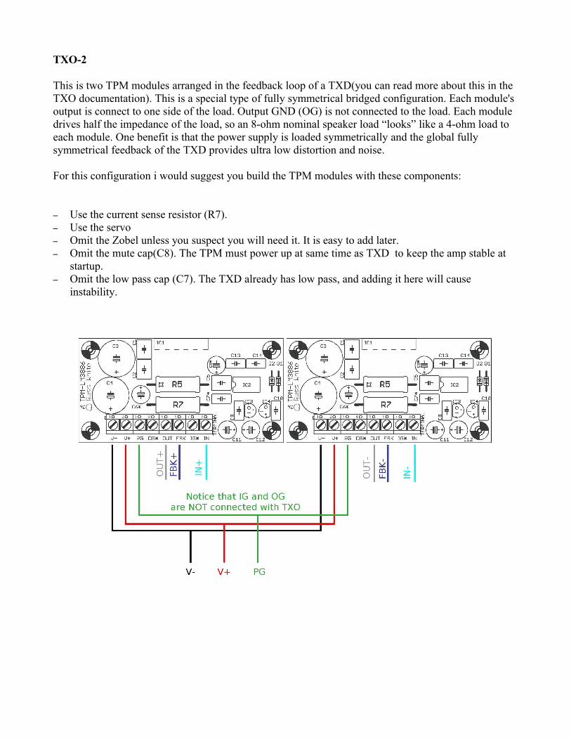
TXO-2
This is two TPM modules arranged in the feedback loop of a TXD(you can read more about this in the TXO documentation). This is a special type of fully symmetrical bridged configuration. Each module's output is connect to one side of the load. Output GND (OG) is not connected to the load. Each module drives half the impedance of the load, so an 8-ohm nominal speaker load “looks” like a 4-ohm load to each module. One benefit is that the power supply is loaded symmetrically and the global fully symmetrical feedback of the TXD provides ultra low distortion and noise.
For this configuration i would suggest you build the TPM modules with these components:
– Use the current sense resistor (R7).– Use the servo– Omit the Zobel unless you suspect you will need it. It is easy to add later.– Omit the mute cap(C8). The TPM must power up at same time as TXD to keep the amp stable at
startup.– Omit the low pass cap (C7). The TXD already has low pass, and adding it here will cause
instability.
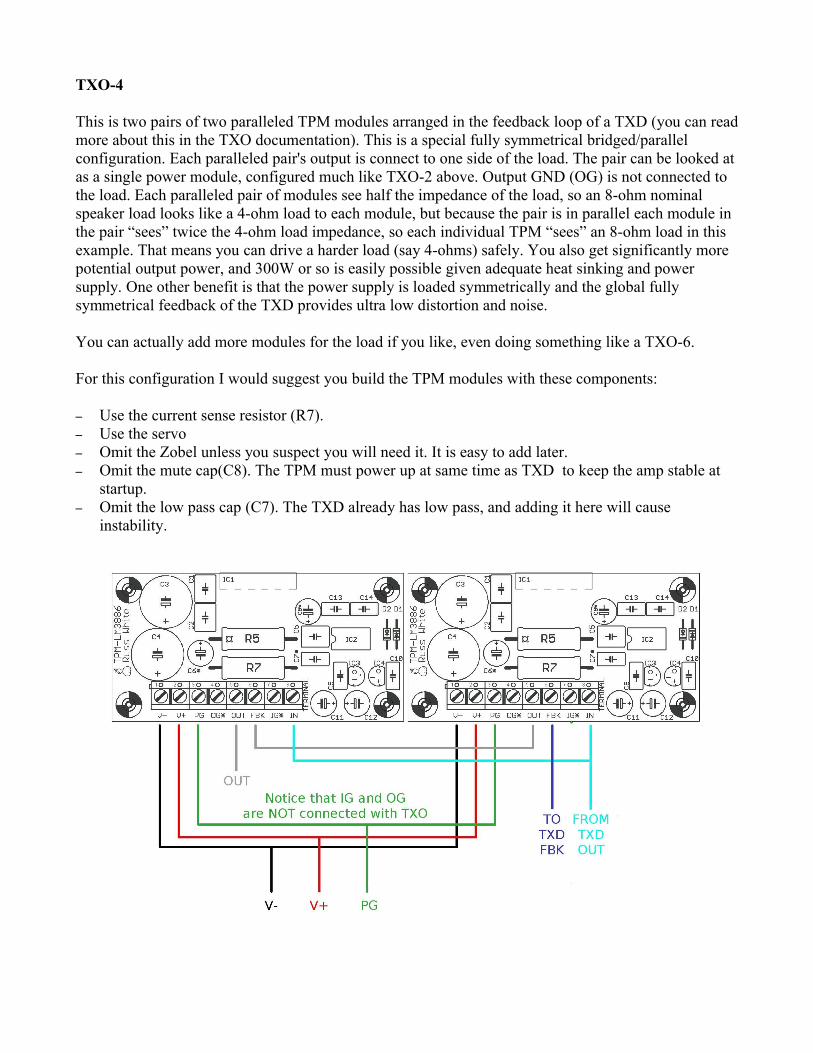
TXO-4
This is two pairs of two paralleled TPM modules arranged in the feedback loop of a TXD (you can read more about this in the TXO documentation). This is a special fully symmetrical bridged/parallel configuration. Each paralleled pair's output is connect to one side of the load. The pair can be looked at as a single power module, configured much like TXO-2 above. Output GND (OG) is not connected to the load. Each paralleled pair of modules see half the impedance of the load, so an 8-ohm nominal speaker load looks like a 4-ohm load to each module, but because the pair is in parallel each module in the pair “sees” twice the 4-ohm load impedance, so each individual TPM “sees” an 8-ohm load in this example. That means you can drive a harder load (say 4-ohms) safely. You also get significantly more potential output power, and 300W or so is easily possible given adequate heat sinking and power supply. One other benefit is that the power supply is loaded symmetrically and the global fully symmetrical feedback of the TXD provides ultra low distortion and noise.
You can actually add more modules for the load if you like, even doing something like a TXO-6.
For this configuration I would suggest you build the TPM modules with these components:
– Use the current sense resistor (R7).– Use the servo– Omit the Zobel unless you suspect you will need it. It is easy to add later.– Omit the mute cap(C8). The TPM must power up at same time as TXD to keep the amp stable at
startup.– Omit the low pass cap (C7). The TXD already has low pass, and adding it here will cause