Two Approaches For Direct Torque Control Using a Three-Level Voltage Source Inverter R. Zaimeddine 1 - E.M. Berkouk 2 Department of Electrical Engineering University of Mouloud Mammeri ,Hasnaoua II ,Tizi Ouzou ALGERIA Abstract: - The object of this paper is to study a new control structure for sensorless induction machine dedicated to electrical drives using a three-level voltage source inverter (VSI). The output voltages of the three- level VSI can be represented by four groups : the zero voltage vectors, the small voltage vectors, the middle voltage vectors and the large voltage vectors in (d , q) plane. Then, the amplitude and the rotating velocity of the flux vector can be controlled freely. Both fast torque and optimal switching logic can be obtained. The selection is based on the value of the stator flux and the torque. Both approaches, classical DTC and fuzzy logic controller, are simulated for a induction motor. The results obtained show superior performances over the FOC one without need to any mechanical sensor. Key Words: - Direct Torque Control, Field Oriented Control, Induction motor, Sensorless Vector Control, Flux Estimators, Switching Strategy Optimisation, Multi-level inverter, Neural-point clamped, fuzzy control. 1 Introduction The rapid development of the capacity and switching frequency of the power semiconductor devices and the continuous advance of the power electronics technology have made many changes in static power converter systems and industrial motor drive areas. The conventional GTO inverters have limitation of their dc-link voltage. Hence, the series connections of the existing GTO thyristors have been essential in realizing high voltage and large capacity inverter configurations with the dc-link voltage [1]. The vector control of induction motor drive has made it possible to be used in applications requiring fast torque control such as traction [2]. In a perfect field oriented control, the decoupling characteristics of the flux and torque are affected highly by the parameter variation in the machine. This paper describes a control scheme for direct torque and flux control of induction machines fed by a three-level inverter using a switching table. In this method, the output voltage is selected and applied sequentially to the machine through a look –up table so that the flux is kept constant and the torque is controlled by the rotating speed of the stator flux. The direct torque control (DTC) is one of the actively researched control scheme which is based on the decoupled control of flux and torque providing a very quick and robust response with a simple control construction in ac drives [3,4]. 2 Three-Level Inverter Topology Fig . 1 shows the schematic diagram of neutral point clamped (NPC) three-level VSI. Each phase of this inverter consists of two clamping diodes, four GTO thyristors and four freewheeling diodes. Table. 1 shows the switching states of this inverter. Since three kinds of switching states exist in each phase, a three level inverter has 27 switching states. Fig. 1. Schematic diagram of a three-level GTO inverter Proceedings of the 6th WSEAS Int. Conf. on FUZZY SYSTEMS, Lisbon, Portugal, June 16-18, 2005 (pp104-110)
Transcript
Two Approaches For Direct Torque Control Using a Three-Level Voltage Source Inverter
R. Zaimeddine1 - E.M. Berkouk2
Department of Electrical Engineering University of Mouloud Mammeri ,Hasnaoua II ,Tizi Ouzou
ALGERIA
Abstract: - The object of this paper is to study a new control structure for sensorless induction machine dedicated to electrical drives using a three-level voltage source inverter (VSI). The output voltages of the three-level VSI can be represented by four groups : the zero voltage vectors, the small voltage vectors, the middle voltage vectors and the large voltage vectors in (d , q) plane. Then, the amplitude and the rotating velocity of the flux vector can be controlled freely. Both fast torque and optimal switching logic can be obtained. The selection is based on the value of the stator flux and the torque. Both approaches, classical DTC and fuzzy logic controller, are simulated for a induction motor. The results obtained show superior performances over the FOC one without need to any mechanical sensor. Key Words: - Direct Torque Control, Field Oriented Control, Induction motor, Sensorless Vector Control, Flux Estimators, Switching Strategy Optimisation, Multi-level inverter, Neural-point clamped, fuzzy control. 1 Introduction The rapid development of the capacity and switching frequency of the power semiconductor devices and the continuous advance of the power electronics technology have made many changes in static power converter systems and industrial motor drive areas. The conventional GTO inverters have limitation of their dc-link voltage. Hence, the series connections of the existing GTO thyristors have been essential in realizing high voltage and large capacity inverter configurations with the dc-link voltage [1]. The vector control of induction motor drive has made it possible to be used in applications requiring fast torque control such as traction [2]. In a perfect field oriented control, the decoupling characteristics of the flux and torque are affected highly by the parameter variation in the machine. This paper describes a control scheme for direct torque and flux control of induction machines fed by a three-level inverter using a switching table. In this method, the output voltage is selected and applied sequentially to the machine through a look –up table so that the flux is kept constant and the torque is controlled by the rotating speed of the stator flux. The direct torque control (DTC) is one of the actively researched control scheme which is based on the decoupled control of flux and torque providing a very quick and robust response with a simple control construction in ac drives [3,4].
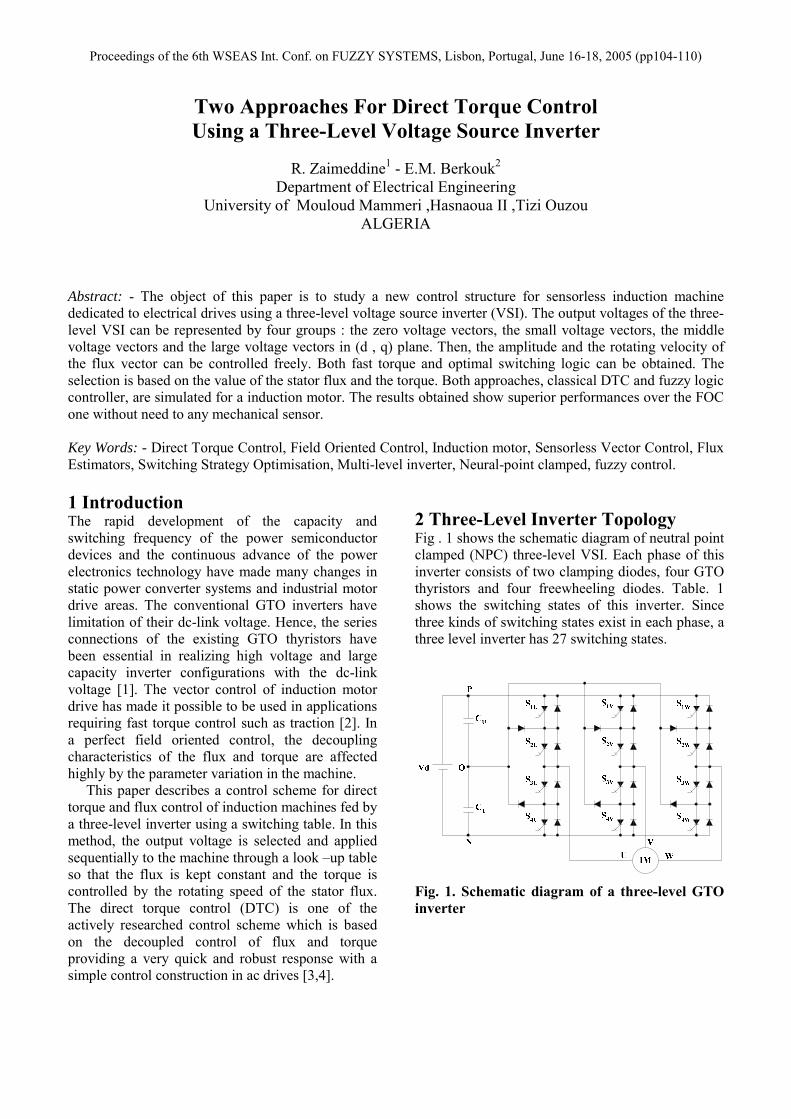
2 Three-Level Inverter Topology Fig . 1 shows the schematic diagram of neutral point clamped (NPC) three-level VSI. Each phase of this inverter consists of two clamping diodes, four GTO thyristors and four freewheeling diodes. Table. 1 shows the switching states of this inverter. Since three kinds of switching states exist in each phase, a three level inverter has 27 switching states. Fig. 1. Schematic diagram of a three-level GTO inverter
Proceedings of the 6th WSEAS Int. Conf. on FUZZY SYSTEMS, Lisbon, Portugal, June 16-18, 2005 (pp104-110)
Table. 1 Switching states of a three-level inverter
Switching states
S1 S2 S3 S4 VN
P ON ON OFF OFF Vd O OFF ON ON OFF Vd/2 N OFF OFF ON ON 0
A two-level inverter is only capable to produce six non-zero voltage vectors and two zero vectors [2]. The representation of the space voltage vectors of a three-level inverter for all switching states, according to the magnitude of the voltage vectors, we divide them into four groups : the zero voltage vectors (V0), the small voltage vectors (V1 , V4 , V7 , V10 , V13 , V16 ), the middle voltage vectors (V3 , V6 , V9 , V12 , V15 , V18 ), the large voltage vectors (V2 , V5 , V8 , V11 , V14 , V17 ). The zero voltage vector (ZVV) has three switching states, the small voltage vector (SVV) have two, and both the middle voltage vector (MVV) and the large voltage vector (LVV) have only one [1]. Fig. 2. Space voltage vectors of a three-level inverter 3 Induction Machine Torque control of an asynchronous motor can be achieved on the basis of its model developed in a two axes (d , q) reference frame stationary with the stator winding. In this reference frame and with conventional notations, the electrical mode is described by the following equations:
sqipsdisTrTsqsL
psdsLrTdt
sddi Ω−+−Ω+= )11(11σϕσϕσ
sdsVLσ
1+ (1)
sdipsqisTrTsqsLrTsdsL
pdtsqdi
Ω++−+Ω−= )11(11σϕσϕσ
sqVsLσ
1+ (2)
sdisRsdVdtsdd −=ϕ (3)
sqssqsq iRVdt
d −=ϕ (4)
The mechanical mode associated to the rotor motion is described by : )(ΩΓ−Γ=Ω remdt
dJ (5)
)(ΩΓr and emΓ are respectively the load torque and
the electromagnetic torque developed by the machine. 4 Stator Flux and Torque Estimation Basically, DTC schemes require the estimation of the stator flux and torque. The stator flux evaluation can be carried out by different techniques depending on whether the rotor angular speed or (position) is measured or not. For sensorless application, the “voltage model” is usually employed [5]. The stator flux can be evaluated by integrating from the stator voltage equation. ∫ −= dtsIsRVsts )()(ϕ (6)
V1
q
♦
♦
d
t=Te
t = 0 θθθθs
ϕϕϕϕso
Vs=V7 ϕϕϕϕs
V
V4 V7
V13 V16
V10
θθθθso
∆∆∆∆θθθθsθθθθνννν
Fig. 3. Flux deviation
θθθθ1 V0
V2
V3
V5 V6 V8
V9
V11
V12
V14
V15 V17
V18
V1
V4 V7
V10
V13 V16
V0 U
V
W
Proceedings of the 6th WSEAS Int. Conf. on FUZZY SYSTEMS, Lisbon, Portugal, June 16-18, 2005 (pp104-110)
This method is very simple requiring the knowledge of the stator resistance only. The effect of an error in Rs is usually quite negligible at high excitation frequency but becomes more serious as the frequency approaches zero [5]. The deviation obtained as the end of the switching period Te can be approached by the first order Taylor Seri as below.
so
svses
svessVT
TV
ϕθθθ
θθϕ)sin(..
)cos(..−≈∆
−≈∆ (7)
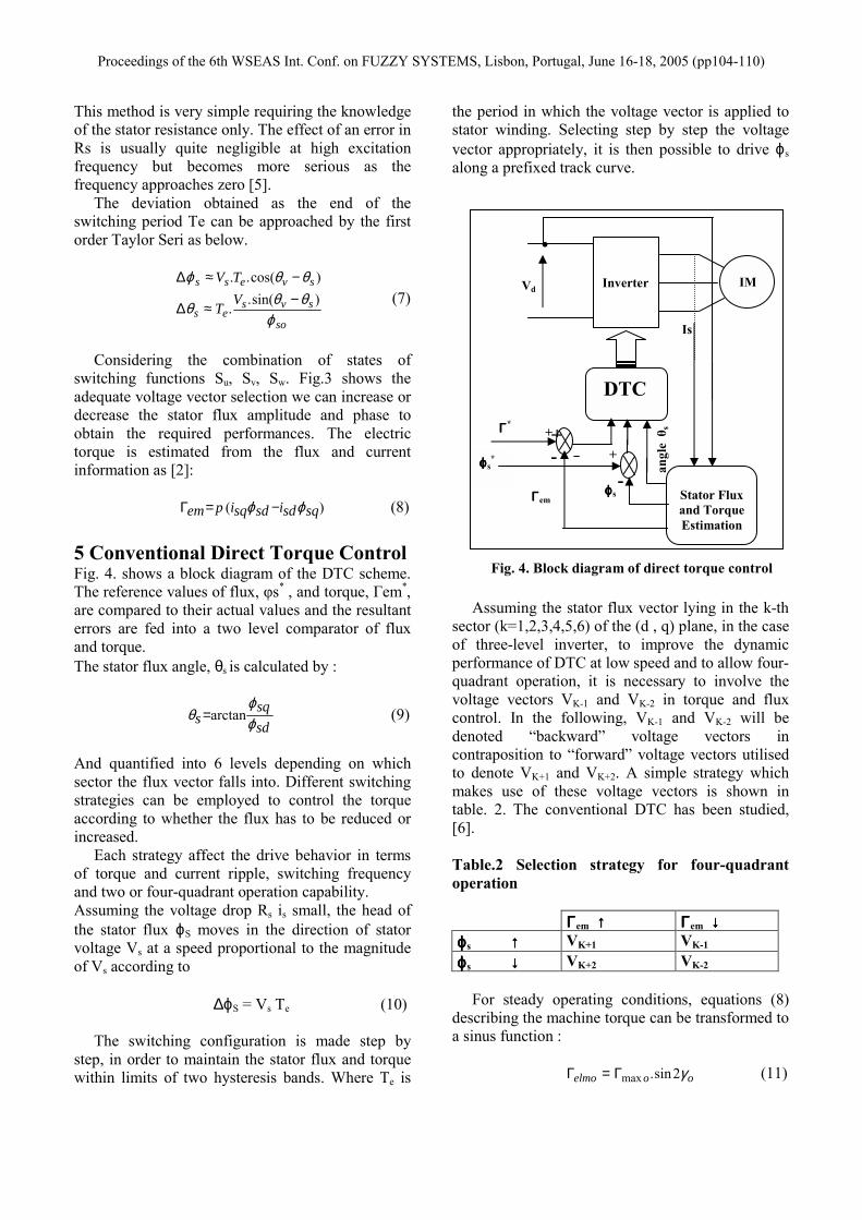
Considering the combination of states of switching functions Su, Sv, Sw. Fig.3 shows the adequate voltage vector selection we can increase or decrease the stator flux amplitude and phase to obtain the required performances. The electric torque is estimated from the flux and current information as [2]: )( sqsdisdsqipem ϕϕ −=Γ (8) 5 Conventional Direct Torque Control Fig. 4. shows a block diagram of the DTC scheme. The reference values of flux, φs* , and torque, Гem*, are compared to their actual values and the resultant errors are fed into a two level comparator of flux and torque. The stator flux angle, θs is calculated by :
sdsq
s ϕϕ
θ arctan= (9)
And quantified into 6 levels depending on which sector the flux vector falls into. Different switching strategies can be employed to control the torque according to whether the flux has to be reduced or increased. Each strategy affect the drive behavior in terms of torque and current ripple, switching frequency and two or four-quadrant operation capability. Assuming the voltage drop Rs is small, the head of the stator flux ϕS moves in the direction of stator voltage Vs at a speed proportional to the magnitude of Vs according to ∆ϕS = Vs Te (10) The switching configuration is made step by step, in order to maintain the stator flux and torque within limits of two hysteresis bands. Where Te is
the period in which the voltage vector is applied to stator winding. Selecting step by step the voltage vector appropriately, it is then possible to drive ϕs along a prefixed track curve. Assuming the stator flux vector lying in the k-th sector (k=1,2,3,4,5,6) of the (d , q) plane, in the case of three-level inverter, to improve the dynamic performance of DTC at low speed and to allow four-quadrant operation, it is necessary to involve the voltage vectors VK-1 and VK-2 in torque and flux control. In the following, VK-1 and VK-2 will be denoted “backward” voltage vectors in contraposition to “forward” voltage vectors utilised to denote VK+1 and VK+2. A simple strategy which makes use of these voltage vectors is shown in table. 2. The conventional DTC has been studied, [6]. Table.2 Selection strategy for four-quadrant operation ΓΓΓΓem ↑↑↑↑ ΓΓΓΓem ↓↓↓↓ ϕϕϕϕs ↑↑↑↑ VK+1 VK-1 ϕϕϕϕs ↓↓↓↓ VK+2 VK-2
For steady operating conditions, equations (8) describing the machine torque can be transformed to a sinus function : ooelmo γ2sin.maxΓ=Γ (11)
Fig. 4. Block diagram of direct torque control
IM
DTC
Stator Flux and Torque Estimation
ϕϕϕϕs*
ΓΓΓΓ*
ΓΓΓΓem ϕϕϕϕs
+
-
+-
Is
Vd
+
-
.Inverter
angl
e θ
s
Proceedings of the 6th WSEAS Int. Conf. on FUZZY SYSTEMS, Lisbon, Portugal, June 16-18, 2005 (pp104-110)
oo and γmaxΓ are equation respectively torque and the difference angle between stator and rotor flux vectors.
rosoosos
o Lp θθγϕ
σσ −=−=Γ ;...2
1. 2max (12)
Equations (11) and (12) are established with the assumption that stator flux and rotor closed values in steady state. For disturbed states, the stator flux angle θs has in practice a fast dynamic mode as compared to the rotor flux angle θr. If these two assumptions are hold the effect of stator vector voltage on the machine torque can be expressed by the first order Taylor expansion as below : sselm KK θϕ θϕ ∆+∆≈∆Γ .. (13) The sensitivity coefficients Kϕ et Kθ are defined by :
Γ=Γ=
Γ=Γ=
oos
elm
elmosos
elm
ddK
ddK
γθ
ϕϕ
θ
ϕ
2cos..2
.2
max
(14)
linking equations (7), (13) and (14) leads to :
)sin(....2
)cos(....2
22max sovelmoo
so
es
sovelmoso
eselm
TV
TV
θθϕ
θθϕ
−Γ−Γ+
−Γ=∆Γ (15)
This shows the feasibility torque control by a well selected vectors voltage Vs [7]. According to this strategy, the stator flux vector is required to rotate in both positive and negative directions. By this, even at very low shaft speed, large negative values of rotor angular frequency can be achieved, which are required when the torque is to be decreased very fast. Furthermore, the selection strategy represented in Table. II allows good flux control to be obtained even in the low speed range. However, the high dynamic performance which can be obtained utilising voltage vectors having large components tangential to the stator vector locus implies very high switching frequency.
6 Switching Strategy Proposed A switching table is used to select the best output voltage depending on the position of the stator flux and desired action on the torque and stator flux. The flux position in the (d , q) plane is quantified in six sectors. Alternative tables exist for specific operation mode. The switching table for the case of a two-level inverter developed by I. Takahashi [2] , it is easily possible to expand the optimal vector selection to include the larger number of voltage vectors produced by three-level inverter. The appropriate vector voltage is selected in the order to reduce the number of commutation and the level of steady-state ripple. For flux control, let the variable Eϕ (Eϕ=ϕs
*-ϕs) be located in one of the three regions fixed by the contraints : Eϕ < Eϕ min , Eϕ min ≤ Eϕ ≤ Eϕ max , Eϕ > Eϕ max . The switable flux level is then bounded by Eϕ min and Eϕmax. The flux control is made by two-level hysteresis comparator. Three regions for flux location are noted, flux as in fuzzy control schemes, by Eϕn (negative), Eϕz (zero) and Eϕp (positive). A high level performance torque control is required. To improve the torque control let of the mismacth EΓ ( EΓ = Γem
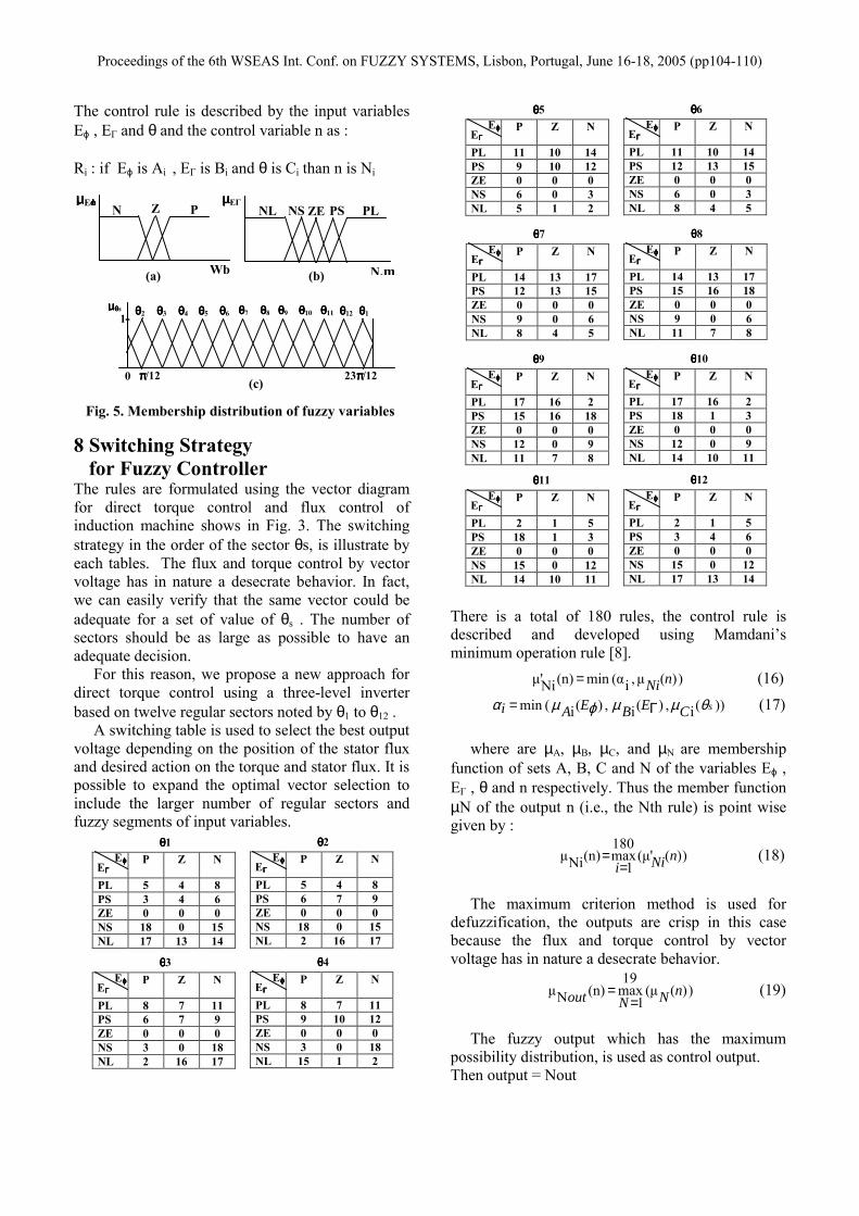
*- Γe ) to belong to one of the five regions defined by the contraints : EΓ < EΓmin2 , EΓmin2 ≤ EΓ ≤ EΓmin1 , EΓmin1 ≤ EΓ ≤ EΓmax1 , EΓmax1 ≤ EΓ ≤ EΓmax2 and EΓmax2 < EΓ . The five regions defined for torque location are also noted, as in fuzzy control schemes, by EΓnl (negative large), EΓns (negative small), EΓz (zero), EΓps (positve small), EΓpl (positve large). The torque is then controlled by an hysteresis comparator built with two lower bounds and two upper known bounds [6]. 7 The Fuzzy Controller Flux error “Eϕ” torque error “EΓ” and flux position “θs” are used as inputs to the fuzzy controller the inverter switchnig state “n” is the output of the controller. The three input variables are divided into their fuzzy segments. The membre of fuzzy segments are chosen to have maximum control with a minimum number of rules. The grade of member distribution of input variables into their fuzzy segments is schows in Fig.5 [8].
Proceedings of the 6th WSEAS Int. Conf. on FUZZY SYSTEMS, Lisbon, Portugal, June 16-18, 2005 (pp104-110)
The control rule is described by the input variables Eϕ , EΓ and θ and the control variable n as : Ri : if Eϕ is Ai , EΓ is Bi and θ is Ci than n is Ni 8 Switching Strategy for Fuzzy Controller The rules are formulated using the vector diagram for direct torque control and flux control of induction machine shows in Fig. 3. The switching strategy in the order of the sector θs, is illustrate by each tables. The flux and torque control by vector voltage has in nature a desecrate behavior. In fact, we can easily verify that the same vector could be adequate for a set of value of θs . The number of sectors should be as large as possible to have an adequate decision. For this reason, we propose a new approach for direct torque control using a three-level inverter based on twelve regular sectors noted by θ1 to θ12 . A switching table is used to select the best output voltage depending on the position of the stator flux and desired action on the torque and stator flux. It is possible to expand the optimal vector selection to include the larger number of regular sectors and fuzzy segments of input variables.
There is a total of 180 rules, the control rule is described and developed using Mamdani’s minimum operation rule [8]. ))(µ,i(αmin(n)'Niµ nNi= (16)
))(i,)(i,)(i(min sCEBEAi θµµϕµα Γ= (17) where are µA, µB, µC, and µN are membership function of sets A, B, C and N of the variables Eϕ , EΓ , θ and n respectively. Thus the member function µN of the output n (i.e., the Nth rule) is point wise given by :
))('(µ180
1max(n)Niµ nNii=
= (18)
The maximum criterion method is used for defuzzification, the outputs are crisp in this case because the flux and torque control by vector voltage has in nature a desecrate behavior.
))((µ19
1max(n)Nµ nNNout =
= (19)
The fuzzy output which has the maximum possibility distribution, is used as control output. Then output = Nout
Proceedings of the 6th WSEAS Int. Conf. on FUZZY SYSTEMS, Lisbon, Portugal, June 16-18, 2005 (pp104-110)
9 The Simulation Results The validity of the proposed DTC scheme for three-level voltage source inverter is proved by the simulation results using Matlab-Simulink. The parameters of motors are given in the Appendix. The used flux and torque mismathes for the approach are expressed in percent with respect to th flux and torque reference values. Eϕ max = 3% , Eϕ min = - 3% , EΓmin1 = - 0.8% ,EΓmin2 = - 3% , EΓmax1 = 0.8% , EΓmax2 = 3%. The simulation results illustrates both the steady state and the transient performance of the proposed torque control scheme. However, the machine has been supposed to run at load.
Ω
−Ω
Γ=Γ .frefemr K (20)
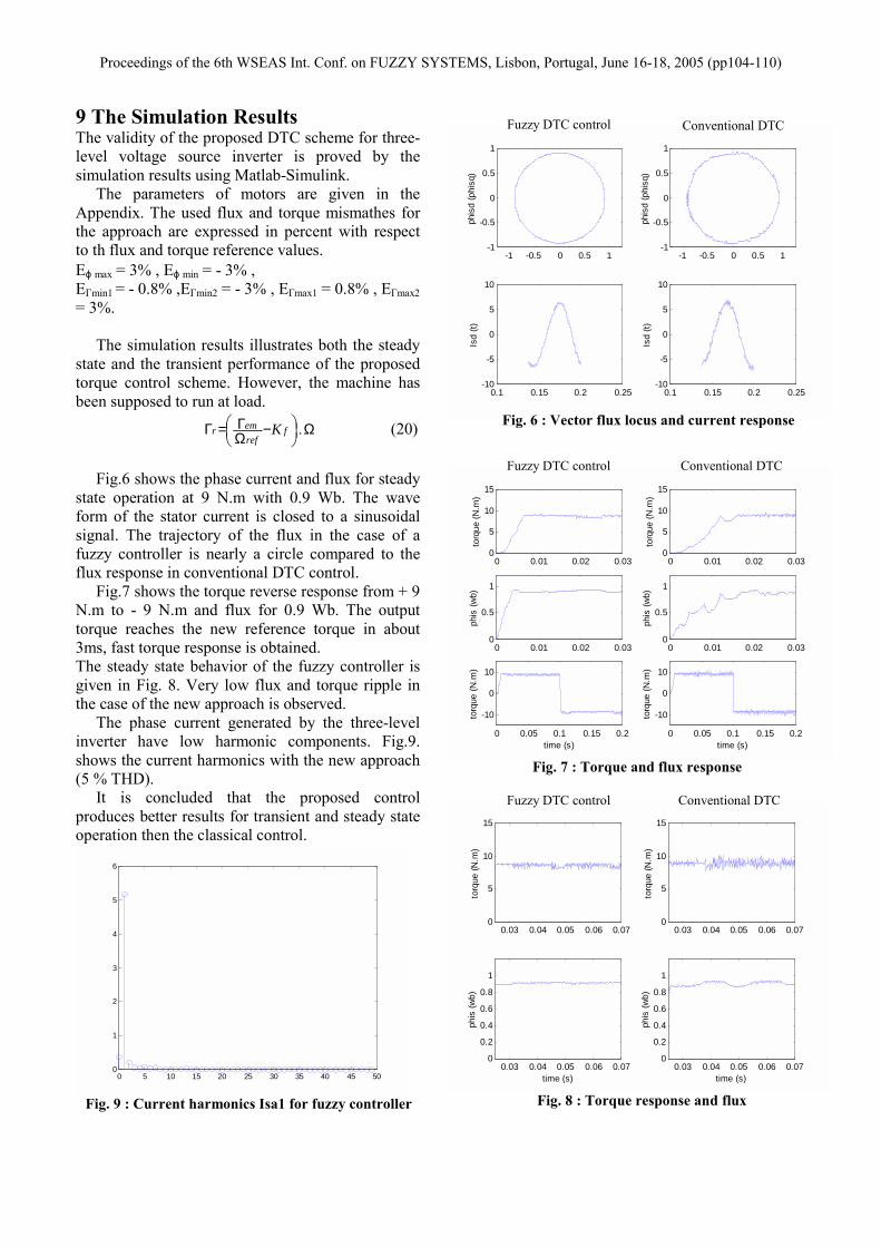
Fig.6 shows the phase current and flux for steady state operation at 9 N.m with 0.9 Wb. The wave form of the stator current is closed to a sinusoidal signal. The trajectory of the flux in the case of a fuzzy controller is nearly a circle compared to the flux response in conventional DTC control. Fig.7 shows the torque reverse response from + 9 N.m to - 9 N.m and flux for 0.9 Wb. The output torque reaches the new reference torque in about 3ms, fast torque response is obtained. The steady state behavior of the fuzzy controller is given in Fig. 8. Very low flux and torque ripple in the case of the new approach is observed. The phase current generated by the three-level inverter have low harmonic components. Fig.9. shows the current harmonics with the new approach (5 % THD). It is concluded that the proposed control produces better results for transient and steady state operation then the classical control.
-1 -0.5 0 0.5 1-1
-0.5
0
0.5
1
phis
d (p
hisq
)
-1 -0.5 0 0.5 1-1
-0.5
0
0.5
1
phis
d (p
hisq
)
0.1 0.15 0.2 0.25-10
-5
0
5
10
Isd
(t)
0.1 0.15 0.2 0.25-10
-5
0
5
10
Isd
(t)
Fuzzy DTC control Conventional DTC
0 0.01 0.02 0.030
5
10
15to
rque
(N.m
)
0 0.01 0.02 0.030
5
10
15
torq
ue (N
.m)
0 0.01 0.02 0.030
0.5
1
phis
(wb)
0 0.01 0.02 0.030
0.5
1
phis
(wb)
0 0.05 0.1 0.15 0.2
-10
0
10
torq
ue (N
.m)
time (s)0 0.05 0.1 0.15 0.2
-10
0
10
torq
ue (N
.m)
time (s)
0.03 0.04 0.05 0.06 0.070
5
10
15
torq
ue (N
.m)
0.03 0.04 0.05 0.06 0.070
5
10
15
torq
ue (N
.m)
0.03 0.04 0.05 0.06 0.070
0.2
0.4
0.6
0.8
1
phis
(wb)
time (s)0.03 0.04 0.05 0.06 0.07
0
0.2
0.4
0.6
0.8
1
phis
(wb)
time (s)0 5 10 15 20 25 30 35 40 45 500
1
2
3
4
5
6
Fuzzy DTC control Conventional DTC
Fuzzy DTC control Conventional DTC
Fig. 6 : Vector flux locus and current response
Fig. 8 : Torque response and flux
Fig. 7 : Torque and flux response
Fig. 9 : Current harmonics Isa1 for fuzzy controller
Proceedings of the 6th WSEAS Int. Conf. on FUZZY SYSTEMS, Lisbon, Portugal, June 16-18, 2005 (pp104-110)
10 Conclusions The direct torque control DTC was introduced to give a fast and good dynamic torque and can be considered as an alternative to the field oriented control FOC technique. It is concluded that the proposed control produces better results for transient and the steady state operation then the conventional control. However, the two approaches indicate a good regulation. In this paper, a DTC systems using three-level GTO voltage source inverter is presented it is suitable for high-power and high-voltage applications. We enhance the DTC approach by introducing fuzzy logic controller. From the analysis of these results establish the following remarks : The fuzzy logic approach has a fast torque and flux response as compared to the conventional DTC. The stator current wave form is more close to the suitable sinusoidal signal in the fuzzy controller case. In fact, on line application and control schemes including parameters correction is suitable used the fuzzy logic criterion. From this analysis high dynamic performance, good stability and precision are achieved. Two problems usually associated with DTC drives which are based on hysteresis comparators are: variable switching frequency and inaccurate stator flux estimation which can degrade the drive performance. Appendix List of the used notations L : magnetizing Inductance Lm : mutual inductance ; V : voltage i : current φ : flux R : resistance Гem : electromagnetic torque J : rotor inertia P : number of pairs of poles ωs : statoric pulsation Vd : dc-link voltage Kf : friction Coefficient Te : sampling time E : error of the variables E : error of the variables. ωr : electric rotor speed ; Ω = p ωr. σ : leakage coefficient,
rsmLL
L.12
−=σ
rT : rotor time response,rrr R
LT =
sT : stator time response,sss R
LT =
Induction motors parameters Rated power : 1.5 kW; Rated voltage : 220 V; Rated speed : 1420 rpm;Rated frequency : 50 Hz; Rated current : 3.64 A (Y) et 6.31 (∆); Stator resistance : 4.85 Ω; Rotor resistance : 3.805 Ω; Stator inductance : 0.274 H; Rotor inductance : 0.274 H; Magnetizing Inductance : 0.258 H; Number of poles : 2 ; Rotor inertia : 0.031 Kg.m2 ; Friction Coefficient : 0.008 N.m.s/rd ; Vdc = 514 v ; Te =100 µs; References: [1] Y.H. Lee, B.S. Suh, and D.S. Hyan, A novel
PWM scheme for a three-level voltage source inverter with GTO thyristors, IEEE Trans. on Ind. Appl, vol. 33 2, March\April 1996, pp. 260-268.
[2] I. Takahashi and T. Noguchi, A new quick-response and high-efficiency control strategy of an induction motor, IEEE Trans. on IA, vol. 22, No. 5, Sept\Octo 1986, pp. 820-827.
[3] J.C. Trounce, S.D. Round, and R..M. Duke, Comparison by simulation of three-level induction motor torque control schemes for electrical vehicle applications, Proc. of international power engineering conference, vol. 1, May 2001, pp. 294-299.
[4] WU. Xuezh, and L. Huang, Direct torque control of three-level inverter using neural networks as switching vector selector, IEEE IAS, annual meeting, 30 September\ 04 October 2001.
[5] D. Casadei, G. Grandi, G. Serra, and A. Tani, Switching strategies in direct torque control of induction machines, ICEM 94, vol. 2, 1994, pp.204-209.
[6] R. Zaimeddine, and E.M. Berkouk, A Novel DTC scheme for a three-level voltage source inverter with GTO thyristor, SPEEDAM 2004, Symposium on power electronics, electrical drives, automation & Motion, June, vol. 2, June, 16th-18th 2004, pp. F1A-9-F1A-12.
[7] F. Bacha, A. sbai, and R. Dhifaui, Tow Approaches For Direct Torque Control of an Induction Motor”, CESA Symposium on control, vol. 1, March 1998, pp. 562-568.
[8] S.A. Mir, M.E. Elbuluk and D.S Zinger fuzzy implementation of direct self control of induction machines, IEEE Trans. on IA, vol. 30, No. 3, May\June 1994, pp. 729-735.
Proceedings of the 6th WSEAS Int. Conf. on FUZZY SYSTEMS, Lisbon, Portugal, June 16-18, 2005 (pp104-110)