TWO-DIMENSIONAL AXISYMMETRIC WINDING MODEL FOR FINITE DEFORMATION K. ÄRÖLÄ 1 , R. VON HERTZEN 2 1 VTT –Technical Research Centre of Finland Smart Machines, Structural Dynamics P.O.Box 1000, FI-02044 VTT, Finland e-mail: kilwa.arola@vtt.fi 2 Lappeenranta University of Technology Laboratory of Fatigue and Strength P.O.Box 20, FIN-53851 Lappeenranta, Finland e-mail: raimo.von.hertzen@lut.fi Abstract A two-dimensional axisymmetric winding model for wound rolls of thin web is devel- oped. The model accounts for radial and axial displacements and radial, circumferential, axial and shear stresses. The roll build-up is modeled as an incremental accretion process. The material behaviour of the roll is considered as hyperelastic, orthotropic and radially nonlinear. The numerical solution is developed using the finite element method and the total Lagrangian formulation. The model is applied to the winding of paper rolls. It is shown that centrifugal forces may considerably affect the resulting stress distributions. For nonzero Poisson’s ratios significant edge effects in the roll stresses are found. In particu- lar, high shear stresses and shear stress gradients are discovered in the vicinity of the core near the roll ends. A remarkable stress leveling phenomenon is found where the effect of a non-constant incoming web tension is evened out in the roll axial direction. 1 Introduction Thin sheet media such as paper, magnetic tape, polymer, and metal are generally wound into compact rolls for the subsequent handling and transportation. The roll form is by far the most economical and practical form of material storage. During the production process, the tensioned thin sheet or web is wrapped on a solid central core. At this stage, the stresses and strains in the roll are built up in an incremental manner. The resulting stresses determine to a large extent the quality of the roll, and provide the most important piece of information for the evaluation of the future durability and functionality of the finished roll. Also, as the trend in winding technology is towards thinner media and faster winding speeds [1], the mechanical stability of the rolls becomes more and more critical. Although experimental data through the sandwiched pull strip method and some other methods can be obtained in laboratory conditions, practical non-destructive techniques to measure the 1
Transcript
TWO-DIMENSIONAL AXISYMMETRIC WINDING MODEL
FOR FINITE DEFORMATION
K. ÄRÖLÄ1, R. VON HERTZEN2
1VTT –Technical Research Centre of FinlandSmart Machines, Structural DynamicsP.O.Box 1000, FI-02044 VTT, Finland
A two-dimensional axisymmetric winding model for wound rolls of thin web is devel-oped. The model accounts for radial and axial displacements and radial, circumferential,axial and shear stresses. The roll build-up is modeled as an incremental accretion process.The material behaviour of the roll is considered as hyperelastic, orthotropic and radiallynonlinear. The numerical solution is developed using the finite element method and thetotal Lagrangian formulation. The model is applied to the winding of paper rolls. It isshown that centrifugal forces may considerably affect the resulting stress distributions. Fornonzero Poisson’s ratios significant edge effects in the roll stresses are found. In particu-lar, high shear stresses and shear stress gradients are discovered in the vicinity of the corenear the roll ends. A remarkable stress leveling phenomenon is found where the effect of anon-constant incoming web tension is evened out in the roll axial direction.
1 Introduction
Thin sheet media such as paper, magnetic tape, polymer, and metal are generally woundinto compact rolls for the subsequent handling and transportation. The roll form is by farthe most economical and practical form of material storage. During the production process,the tensioned thin sheet or web is wrapped on a solid central core. At this stage, thestresses and strains in the roll are built up in an incremental manner. The resulting stressesdetermine to a large extent the quality of the roll, and provide the most important pieceof information for the evaluation of the future durability and functionality of the finishedroll. Also, as the trend in winding technology is towards thinner media and faster windingspeeds [1], the mechanical stability of the rolls becomes more and more critical. Althoughexperimental data through the sandwiched pull strip method and some other methods canbe obtained in laboratory conditions, practical non-destructive techniques to measure the
1
internal state of stress of a roll on a production line are still lacking. This applies to finishedrolls as well as to rolls still in a wind up. Thus, to evaluate the quality of the winding, thereis an obvious need for a physical model of the winding process.
There are several roll defects which may result from nonoptimal stress distributions ina roll. Lack of tension may cause cinching, telescoping and spoking while excessive stressescan lead to increased creep, interlayer buckling, core collapse and starring [2, 3, 4, 5, 6]. Itis known, for example, that desirable radial stresses are large enough to prevent individuallayers from slipping, but not too large, to avoid surface damage. However, since the stressbuild up in a winding roll is a complex process, a reliable roll model is needed to quantifythe contribution of various factors influencing the roll quality. In this way design criteriafor the roll’s state of stress can be developed.
Although winding is a continuous process, it has generally been modeled as an incremen-tal process where successive pretensioned circular hoops are shrunk-fit onto the underlyingroll. The motivation for the axisymmetry stems from the fact that any dependence on theazimuth angle is averaged out due to the rolling nip which makes hundreds or thousands ofrevolutions during a wind up. Thus, the roll is assumed to be a collection of single concentrichoops stuck together. This is an example of an accretion problem of solid mechanics or ofthe mechanics of growing bodies. Typical other examples are a solidifying body, a growingcrystal, a growing solid surface due to spray deposition etc. All such bodies consist of masselements that became part of the growing body at different times and at different initialstresses. It is typical of growing bodies that a configuration in which the elements of thebody would be connected in a stress free state does not exists. This implies that the straintensor does not satisfy the conventional compatibility condition. It can be shown, however,that the compatibility condition is satisfied when expressed in terms of strain incrementsor strain rates.
There is an extensive literature on the mechanics of wound rolls. The developed modelscan be used for the calculation of internal stress and small deformation distributions ofwound rolls. Most of them are one-dimensional accounting for the radial change of thestress and displacement fields only. The one-dimensional models can be grouped into fourcategories according to the constitutive law of the modeled roll. These constitutive lawshave been linearly [7, 8, 9] or nonlinearly [10, 11, 12] elastic and linearly [13, 14, 15] ornonlinearly [16] viscoelastic and have treated the material as being orthotropic. The rollhas been considered in a plane stress or plane strain state corresponding to very short orlong rolls, respectively (magnetic tape packs or large paper rolls, for example), in whichuniform mechanical properties along the roll’s axial direction are assumed.
Recently, a few models treating the roll as a two-dimensional system have been pub-lished [4, 5, 6, 17]. In these models, the core and web regions are considered to be offinite width. The stresses and strains are allowed to vary both in the roll’s radial and axialdirections, and four stress components - radial, circumferential, axial, and shear - as wellas two displacements - radial and axial - are included. With these models, nonuniformwinding tension, web thickness, elastic moduli, and core stiffness, depending on the axialcoordinate, can be treated. In these works, the model has been applied to magnetic tapepacks. Zabaras and Liu [4] have examined the effect of the nonuniform winding tension onthe stresses in the tape pack. Lee and Wickert [5, 6] have treated several realistic cartridgehub (core) designs, and the roles of hub compliance and wound-in tension gradients in set-ting the tape pack’s stress field are considered. Lately, Li and Cao have presented a hybridapproach for the winding process of thin-sheet coils [17]. They develop an approximatemulti-layer finite element model to study the coil deformation under gravitational loading.They use in their finite element model the stresses calculated by an incremental winding
2
model as initial stresses for the subsequent analysis of the "soft coil" problem and othertwo-dimensional phenomena. It should be noted, however, that their winding model itselfis one-dimensional.
In many winding applications the displacements can be large and the displacementgradients are not small compared to unity. This applies particularly in paper winding, wherethe radial strains of the paper rolls take typically values of the order 5−10%, and even 15%in the case of certain soft paper boards. Therefore, the infinitesimal strain theory, utilizedusually for strains well below 1%, is not a good approximation for such rolls. Also, as thewinding speeds continuously increase due to larger production demands, centrifugal forcesmay have a significant effect on the resulting stress distributions. Although Benson [12]has treated large deformations in winding and Olsen [18] the effect of centrifugal forces,their models have been one-dimensional. A unified treatment of large deformations andcentrifugal forces in a two-dimensional winding model has not yet been presented.
In this work, a two-dimensional winding model for predicting the stress and strain fieldswithin a wound roll of web material, in which the radial, circumferential, transverse, andshear stresses, and the radial and axial strains can vary in both the roll’s radial and axial(cross-web) directions, is presented. The material behaviour of the roll is considered asorthotropically anisotropic, linearly elastic in the circumferential and axial directions andnonlinearly elastic in the radial direction. It should be noted that the elastic properties ofthe bulk roll, and the nonlinear radial modulus in particular, may be quite different fromthose of a single isolated layer, and are strongly affected by air entrainment in the roll,asperity compliance at the individual web surfaces, ambient air temperature and humidity,and other factors. The roll is built up in an incremental manner and total equilibrium inthe roll is required after adding of each single hoop. Here the tensioned hoop is allowedto shrink on the surface of the underlying roll, so that the wound-in tension loss [19] isautomatically accounted for. The effect of centrifugal forces is also taken into account.The numerical solution is developed using the finite element method. In particular, finitestrains are incorporated in the model using the total Lagrangian formulation. Also the coreis modeled by the finite element method so that cores with nonlinear material behaviourcan be treated. The model is applied for the analysis of paper rolls. The effect of the finitewidth of the roll on the stresses inside the roll and near the roll’s free ends is studied. Also,the effect of a nonuniform distribution of the incoming winding tension in the roll axialdirection is discussed.
The paper proceeds as follows. In Sections 2 and 3 the governing equations of the rollmodel, and the finite element equations utilizing the total Lagrangian formulation for finitestrains, are developed. In Section 4 the linearization and solution of the nonlinear set ofequations is demonstrated. The formulation of the constitutive equations of a paper roll areconsidered in Section 5. The outline of the simulated winding procedure and the referenceconfiguration are discussed in Section 6. In Section 7 numerical results for several windingexamples are presented. Finally, the conclusions are drawn in Section 8.
2 Axisymmetrical kinematics
In this work the kinematics of the roll is described by using the reference description,in which the independent variable is the position X of a particle or material point in areference configuration. Let eR, eΘ and eZ be the unit base vectors in the cylindricalcoordinate system of Fig. 1. The position of a material point in the undeformed referenceconfiguration is expressed as
X = R eR + Z eZ , (1)
3
ez
eZ
XZ
Y
undeformed
deformedeθ
er
eReΘ
Θ
φ
θ
u = ueR + veΘ + weZ
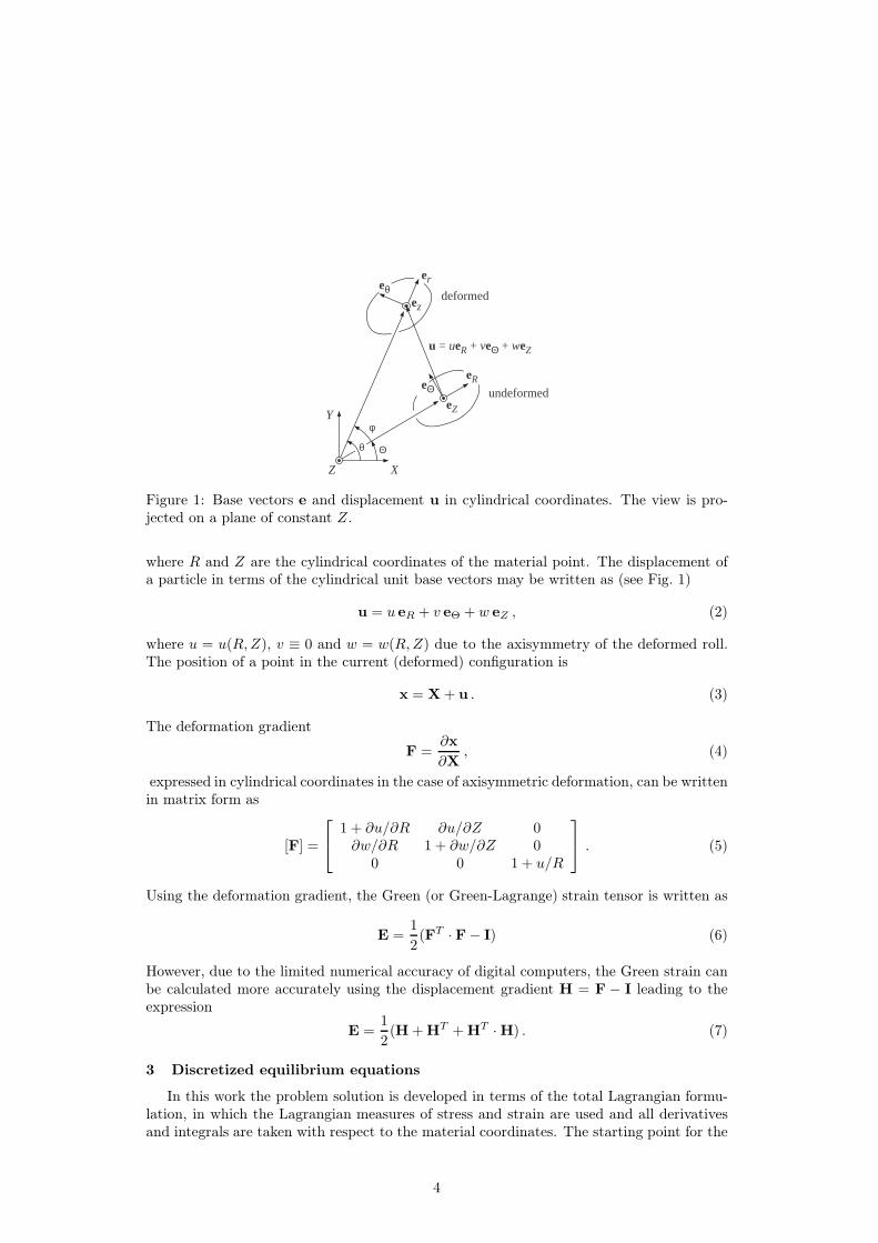
Figure 1: Base vectors e and displacement u in cylindrical coordinates. The view is pro-jected on a plane of constant Z.
where R and Z are the cylindrical coordinates of the material point. The displacement ofa particle in terms of the cylindrical unit base vectors may be written as (see Fig. 1)
u = u eR + v eΘ + w eZ , (2)
where u = u(R,Z), v ≡ 0 and w = w(R,Z) due to the axisymmetry of the deformed roll.The position of a point in the current (deformed) configuration is
x = X + u . (3)
The deformation gradient
F =∂x
∂X, (4)
expressed in cylindrical coordinates in the case of axisymmetric deformation, can be writtenin matrix form as
[F] =
1 + ∂u/∂R ∂u/∂Z 0∂w/∂R 1 + ∂w/∂Z 0
0 0 1 + u/R
. (5)
Using the deformation gradient, the Green (or Green-Lagrange) strain tensor is written as
E =1
2(FT · F− I) (6)
However, due to the limited numerical accuracy of digital computers, the Green strain canbe calculated more accurately using the displacement gradient H = F − I leading to theexpression
E =1
2(H + HT + HT · H) . (7)
3 Discretized equilibrium equations
In this work the problem solution is developed in terms of the total Lagrangian formu-lation, in which the Lagrangian measures of stress and strain are used and all derivativesand integrals are taken with respect to the material coordinates. The starting point for the
4
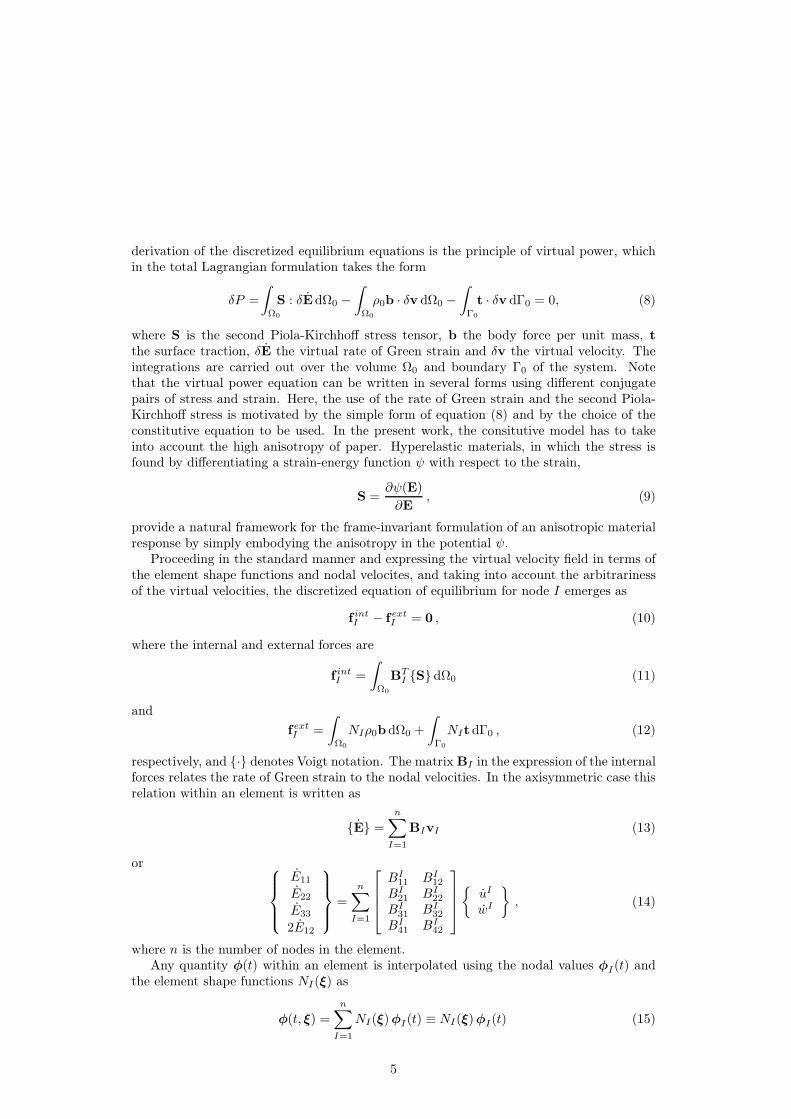
derivation of the discretized equilibrium equations is the principle of virtual power, whichin the total Lagrangian formulation takes the form
δP =
∫
Ω0
S : δE dΩ0 −
∫
Ω0
ρ0b · δv dΩ0 −
∫
Γ0
t · δv dΓ0 = 0, (8)
where S is the second Piola-Kirchhoff stress tensor, b the body force per unit mass, t
the surface traction, δE the virtual rate of Green strain and δv the virtual velocity. Theintegrations are carried out over the volume Ω0 and boundary Γ0 of the system. Notethat the virtual power equation can be written in several forms using different conjugatepairs of stress and strain. Here, the use of the rate of Green strain and the second Piola-Kirchhoff stress is motivated by the simple form of equation (8) and by the choice of theconstitutive equation to be used. In the present work, the consitutive model has to takeinto account the high anisotropy of paper. Hyperelastic materials, in which the stress isfound by differentiating a strain-energy function ψ with respect to the strain,
S =∂ψ(E)
∂E, (9)
provide a natural framework for the frame-invariant formulation of an anisotropic materialresponse by simply embodying the anisotropy in the potential ψ.
Proceeding in the standard manner and expressing the virtual velocity field in terms ofthe element shape functions and nodal velocites, and taking into account the arbitrarinessof the virtual velocities, the discretized equation of equilibrium for node I emerges as
f intI − fext
I = 0 , (10)
where the internal and external forces are
f intI =
∫
Ω0
BTI S dΩ0 (11)
and
fextI =
∫
Ω0
NIρ0b dΩ0 +
∫
Γ0
NIt dΓ0 , (12)
respectively, and · denotes Voigt notation. The matrix BI in the expression of the internalforces relates the rate of Green strain to the nodal velocities. In the axisymmetric case thisrelation within an element is written as
E =
n∑
I=1
BIvI (13)
or
E11
E22
E33
2E12
=
n∑
I=1
BI11 BI
12
BI21 BI
22
BI31 BI
32
BI41 BI
42
uI
wI
, (14)
where n is the number of nodes in the element.Any quantity φ(t) within an element is interpolated using the nodal values φI(t) and
the element shape functions NI(ξ) as
φ(t, ξ) =n
∑
I=1
NI(ξ)φI(t) ≡ NI(ξ)φI(t) (15)
5
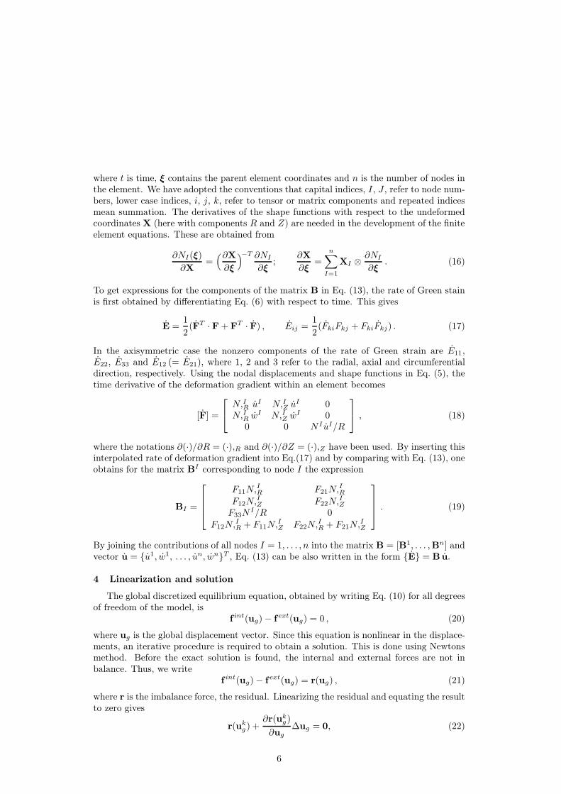
where t is time, ξ contains the parent element coordinates and n is the number of nodes inthe element. We have adopted the conventions that capital indices, I, J , refer to node num-bers, lower case indices, i, j, k, refer to tensor or matrix components and repeated indicesmean summation. The derivatives of the shape functions with respect to the undeformedcoordinates X (here with components R and Z) are needed in the development of the finiteelement equations. These are obtained from
∂NI(ξ)
∂X=
(∂X
∂ξ
)
−T ∂NI
∂ξ;
∂X
∂ξ=
n∑
I=1
XI ⊗∂NI
∂ξ. (16)
To get expressions for the components of the matrix B in Eq. (13), the rate of Green stainis first obtained by differentiating Eq. (6) with respect to time. This gives
E =1
2(FT ·F + FT · F) , Eij =
1
2(FkiFkj + FkiFkj) . (17)
In the axisymmetric case the nonzero components of the rate of Green strain are E11,E22, E33 and E12 (= E21), where 1, 2 and 3 refer to the radial, axial and circumferentialdirection, respectively. Using the nodal displacements and shape functions in Eq. (5), thetime derivative of the deformation gradient within an element becomes
[F] =
N,IR uI N,IZ uI 0
N,IR wI N,IZ w
I 00 0 N I uI/R
, (18)
where the notations ∂(·)/∂R = (·),R and ∂(·)/∂Z = (·),Z have been used. By inserting thisinterpolated rate of deformation gradient into Eq.(17) and by comparing with Eq. (13), oneobtains for the matrix BI corresponding to node I the expression
BI =
F11N,IR F21N,
IR
F12N,IZ F22N,
IZ
F33NI/R 0
F12N,IR + F11N,
IZ F22N,
IR + F21N,
IZ
. (19)
By joining the contributions of all nodes I = 1, . . . , n into the matrix B = [B1, . . . ,Bn] andvector u = u1, w1, . . . , un, wnT , Eq. (13) can be also written in the form E = Bu.
4 Linearization and solution
The global discretized equilibrium equation, obtained by writing Eq. (10) for all degreesof freedom of the model, is
f int(ug) − fext(ug) = 0 , (20)
where ug is the global displacement vector. Since this equation is nonlinear in the displace-ments, an iterative procedure is required to obtain a solution. This is done using Newtonsmethod. Before the exact solution is found, the internal and external forces are not inbalance. Thus, we write
f int(ug) − fext(ug) = r(ug) , (21)
where r is the imbalance force, the residual. Linearizing the residual and equating the resultto zero gives
r(ukg) +
∂r(ukg)
∂ug
∆ug = 0, (22)
6
where k refers to the iteration number. Solving for ∆ug gives the increment in displacement
∆ug = −(∂r(uk
g)
∂ug
)
−1
r(ukg) . (23)
The next estimate for the solution is then obtained from uk+1 = ukg +∆ug. This procedure
is repeated until the solution is found at a prescribed accuracy. In the linearization process(21) we need to relate differentials of the internal and external forces to differentials of thenodal displacements. Using the superposed dot notation for convenience, this is written as
f int = Kintg ug and fext = Kext
g ug . (24)
The matrices Kintg and Kext
g will be formed next.
4.1 Linearization of the internal forces
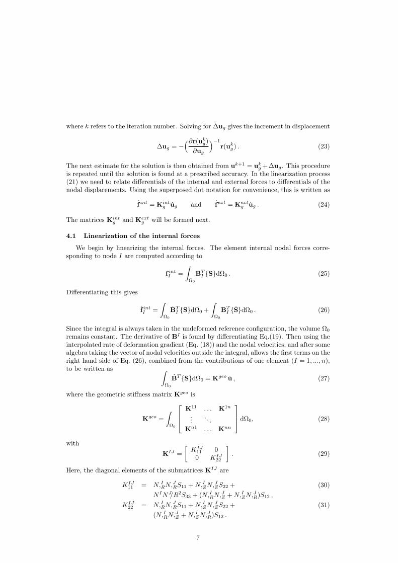
We begin by linearizing the internal forces. The element internal nodal forces corre-sponding to node I are computed according to
f intI =
∫
Ω0
BTI SdΩ0 . (25)
Differentiating this gives
f intI =
∫
Ω0
BTI SdΩ0 +
∫
Ω0
BTI SdΩ0 . (26)
Since the integral is always taken in the undeformed reference configuration, the volume Ω0
remains constant. The derivative of BI is found by differentiating Eq.(19). Then using theinterpolated rate of deformation gradient (Eq. (18)) and the nodal velocities, and after somealgebra taking the vector of nodal velocities outside the integral, allows the first terms on theright hand side of Eq. (26), combined from the contributions of one element (I = 1, ..., n),to be written as
∫
Ω0
BT SdΩ0 = Kgeo u , (27)
where the geometric stiffness matrix Kgeo is
Kgeo =
∫
Ω0
K11 . . . K1n
.... . .
Kn1 . . . Knn
dΩ0, (28)
with
KIJ =
[
KIJ11 00 KIJ
22
]
. (29)
Here, the diagonal elements of the submatrices KIJ are
KIJ11 = N,IRN,
JRS11 +N,IZN,
JZS22 + (30)
N INJ/R2S33 + (N,IRN,JZ +N,IZN,
JR)S12 ,
KIJ22 = N,IRN,
JRS11 +N,IZN,
JZS22 + (31)
(N,IRN,JZ +N,IZN,
JR)S12 .
7
The second term on the right hand side of Eq. (26) can be formed by using the consti-tutive equation. Differentiation of the hyperelastic constitutive equation, Eq. (9), gives forthe time derivative of S the expression
S =∂2ψ
∂E∂E: E = CSE : E . (32)
Writing this in matrix form using Voigt notation and utilizing the expression E = Bu
for the rate of Green strain gives for the material stiffness matrix
Kmat =
∫
Ω0
BT [CSE ]B dΩ0 . (33)
The total tangent stiffness is given by the sum of the geometric and material stiffnessesKint = Kgeo + Kmat. The global matrix Kint
g is assembled by joining the contributionsfrom all elements.
4.2 Linearization of the external forces
The centrifugal force caused by the rotation of the roll is taken into account as a bodyforce. The element nodal force for node I due to a general body force b is
fextI =
∫
Ω0
N Iρ0b dΩ0 , (34)
where ρ0 is the density of the material in the reference state. A constant angular velocityω introduces the force b = ω2r er per unit mass, where r is the current radius. Since thebody force depends on the current radius r, and is thus a function of the displacement, ithas to be linearized for the equilibrium iteration process. By differentiating the expressionfor the external forces the load stiffness Kext for one element due to the centrifugal force isfound to be
Kext =
∫
Ω0
NT
[
ω2 00 0
]
N dΩ0, (35)
where
N =
[
N1 0 . . . Nn 00 N1 . . . 0 Nn
]
. (36)
The global matrix Kextg is assembled by joining the contributions from all elements. How-
ever, since the cumulative process of building the roll requires a large number of steps inwhich elements are added to the roll, the displacements during one load step are small.Considering this, and the magnitudes of the roll angular velocities found in practice, thelinearization of the centrifugal force is not mandatory. In many cases it is, in fact, computa-tionally more efficient to discard the linearization of the centrifugal force from the Jacobianof the residual.
5 Constitutive equations
In many winding applications the displacements can be large and displacement gradientsare not small compared to unity. In paper winding, for example, the radial strains of therolls take typically values of the order 5 − 10%, and even 15% in the case of certain softpaper boards. Therefore, the infinitesimal strain theory, utilized usually for strains wellbelow 1%, is not a good approximation for such rolls. In the present work finite strains areincorporated into the model by employing the total Lagrangian formulation.
8
Most of the thin sheet media wound into rolls exhibit orthotropic material symmetry.The symmetry group for an orthotropic material is generated by the set of reflections R(a),R(b), and R(c) in three orthogonal planes normal to the mutually orthogonal vectors a,b, and c specifying the directions of orthotropy of the material. The symmetry group istherefore comprised of the tensors
where Q(a)(π), Q(b)(π) and Q(c)(π) denote rotations through an angle π about the di-rections of a, b, and c, respectively. In the present work the wound roll is modeled as ahyperelastic material so that an elastic potential function exists. The stress-strain relationmay then be written as
SIJ =∂ψ(E)
∂EIJ
, (38)
where SIJ and EIJ are the components of the second Piola-Kirchhoff stress tensor andthe Green strain tensor, respectively, and ψ the strain energy per unit undeformed volume(symmetrized in EIJ and EJI). For an orthotropic hyperelastic material, ψ(E) must beinvariant under each of the transformations (37). It is well known from group theoreticalconsiderations that any scalar invariant may be expressed as a single-valued function ofthe elements of the irreducible integrity basis. The irreducible integrity basis, on the otherhand, consists of a finite number of polynomial scalar invariants of the tensor, none of whichis expressible as a polynomial in the remaining ones. It has been shown in [20] that theirreducible integrity basis for the tensor E in the case of orthotropic material symmetryconsists of the seven invariants
I1 = trE, I2 =1
2((trE)2 − trE2)), I3 = detE
I4 = a · E · a, I5 = a · E2 · a (39)
I6 = b · E · b, I7 = b · E2 · b
Note that the directions of the vectors a and b, which characterize the anisotropy of thematerial, may vary from point to point corresponding to the case where the fibres arearranged along curves which are not straight lines. For wound rolls the material directionsare a = eR and b = eΘ, where eR and eΘ, unit vectors of the cylindrical coordinate system,are normal to two planes of reflectional symmetry of the roll in the reference (or undeformed)configuration. For the orthotropic hyperelastic material, then, the strain-energy ψ = ψ(E)can depend on E only through these seven invariants so that
ψ = ψ(I1, I2, ..., I7). (40)
A strain-energy function of this form ensures the material frame indifference (objectivity)and orthotropic material symmetry properties of the constitutive equations (38). In thiswork, the deformation of the roll is restricted to axisymmetric cases. A straightforwardcalculation shows that for axisymmetric cases (ERΘ = EΘZ = 0) the invariants (39) become
I1 = ERR + EZZ + EΘΘ,
I2 = ERREZZ + ERREΘΘ + EZZEΘΘ − E2RZ ,
I3 = ERREZZEΘΘ − E2RZEΘΘ,
9
I4 = ERR, (41)
I5 = E2RR + E2
RZ ,
I6 = EΘΘ,
I7 = E2ΘΘ.
It can be easily seen from equations (41) that, in this axisymmetric case, the invariants I2,I3 and I7 can be expressed as polynomials in the invariants I1, I4, I5 and I6. The remainingrelations can be written in the form
I4 = ERR, I6 = EΘΘ, (42)
I1 − I4 − I6 = EZZ , I5 − I24 = E2
RZ .
The most straightforward way to create the constitutive equations would be the specificationof the functional dependence of the strain energy on the invariants I1, I4, I5 and I6. In thefollowing, however, a slightly different approach is chosen. The motivation for this approachis that in the small strain limit it restores a well-established constitutive relation used byseveral authors. The starting point is the complementary strain energy ψ∗ = ψ∗(S) in theform
ψ∗(S) =C0
C21
(1 −C1
C0SRR)[ln(1 −
C1
C0SRR) − 1] (43)
+ ARΘSRRSΘΘ +ARZSRRSZZ +AΘZSΘΘSZZ
+1
2AΘΘS
2ΘΘ +
1
2AZZS
2ZZ +
1
8BRZ(SRZ + SZR)2
The corresponding strain-stress relation EIJ = ∂ψ∗/∂SIJ becomes
ERR = −1
C1ln(1 −
C1
C0SRR) +ARΘSΘΘ +ARZSZZ ,
EΘΘ = ARΘSRR +AΘΘSΘΘ +AΘZSZZ , (44)
EZZ = ARZSRR +AΘZSΘΘ +AZZSZZ ,
ERZ =1
2BRZSRZ .
The first three equations can be (numerically) inverted to give the relationsSRR =SRR(ERR, EΘΘ, EZZ), SΘΘ =SΘΘ(ERR, EΘΘ, EZZ) and SZZ =SZZ(ERR, EΘΘ, EZZ).The fourth equation determines the relation SRZ = 2B−1
RZERZ . Noting that S and E areconjugate variables and by utilizing the proper Legendre transformation, the correspondingstrain energy ψ = ψ(E) is obtained as
Thus, the constitutive equations (44) can be derived from a strain-energy function (46),which is a single-valued function of the elements of the irreducible integrity basis. Conse-quently, the material frame indifference and orthotropic symmetry requirements for a finite
10
strain analysis are fulfilled. Finally, it will be noted that the incremental form of equations(44) is
∆ERR =1
C0 − C1SRR
∆SRR +ARΘ∆SΘΘ +ARZ∆SZZ ,
∆EΘΘ = ARΘ∆SRR +AΘΘ∆SΘΘ +AΘZ∆SZZ , (47)
∆EZZ = ARZ∆SRR +AΘZ∆SΘΘ +AZZ∆SZZ ,
∆ERZ =1
2BRZ∆SRZ .
A similar form or its counterpart for one-dimensional models has been used by severalauthors in small strain wound roll models [4, 10]. The first term on the right hand sideof the first equation corresponds to the tangent radial modulus Er = C0 − C1σr, whichwas introduced by Pfeiffer in a one-dimensional small strain winding analysis [21]. In thesmall strain regime, the elastic constants of equation (47) correspond to the conventionalengineering constants as shown in Table 1. Here Eθ and Ez are the elastic moduli of the
Table 1: Correspondence between the current material parameters and the engineeringelastic constants.
Current Engineering Current EngineeringAΘΘ 1/Eθ ARΘ −νθr/Eθ
AZZ 1/Ez ARZ −νzr/Ez
BRZ 1/Grz AΘZ −νzθ/Ez
roll in the circumferential and axial directions, Grz is the shear modulus in the rz-plane,and νθr, νzr, νzθ are the Poisson’s ratios of the roll.
6 Reference configuration
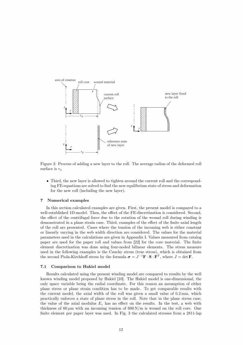
The characterisation of deformation requires an initial or reference configuration, towhich the current configuration is compared. In the present case, the most convenientchoice is to consider the state of the incoming web before it is attached to the roll as thereference state. The refence state and the steps in the process of adding a new layer tothe roll are depicted in Fig. 2. Since each added layer has its own initial displacement andstrain state at the time when it becomes part of the growing roll, the strain field of theroll is, in general, discontinuous. After the attachment of a new layer, the roll and the newlayer form a continuous medium and the displacements from here on are continuous.
In the present model, the process of adding a new layer on the roll can be divided intothree steps.
• First, the reference state of the new layer is a cylindrical shell with a circumferentialstrain equal to the strain of the incoming web and with an inner radius ra and shellthickness h. The dimension ra is the average radius of the current roll outer surfaceas shown in Fig 2.
• Second, displacements of the inner surface of the new layer are prescribed so thatthey bring this surface in contact with the current roll outer surface. The surfaces arefixed together so that from here on their displacements are equal.
11
roll core wound material
current roll surface
reference stateof new layer
new layer fixed to the roll
axis of rotation
ra
zr
zr
ra
zr
Figure 2: Process of adding a new layer to the roll. The average radius of the deformed rollsurface is ra
• Third, the new layer is allowed to tighten around the current roll and the correspond-ing FE-equations are solved to find the new equilibrium state of stress and deformationfor the new roll (including the new layer).
7 Numerical examples
In this section calculated examples are given. First, the present model is compared to awell-established 1D-model. Then, the effect of the FE-discretization is considered. Second,the effect of the centrifugal force due to the rotation of the wound roll during winding isdemonstrated in a plane strain case. Third, examples of the effect of the finite axial lengthof the roll are presented. Cases where the tension of the incoming web is either constantor linearly varying in the web width direction are considered. The values for the materialparameters used in the calculations are given in Appendix I. Values measured from catalogpaper are used for the paper roll and values from [22] for the core material. The finiteelement discretization was done using four-noded bilinear elements. The stress measureused in the following examples is the Cauchy stress (true stress), which is obtained fromthe second Piola-Kirchhoff stress by the formula σ = J−1F · S ·FT , where J = detF.
7.1 Comparison to Hakiel model
Results calculated using the present winding model are compared to results by the wellknown winding model proposed by Hakiel [10]. The Hakiel model is one-dimensional, theonly space variable being the radial coordinate. For this reason an assumption of eitherplane stress or plane strain condition has to be made. To get comparable results withthe current model, the axial width of the roll was given a small value of 0.2 mm, whichpractically enforces a state of plane stress in the roll. Note that in the plane stress case,the value of the axial modulus Ez has no effect on the results. In the test, a web withthickness of 60µm with an incoming tension of 600 N/m is wound on the roll core. Onefinite element per paper layer was used. In Fig. 3 the calculated stresses from a 2811-lap
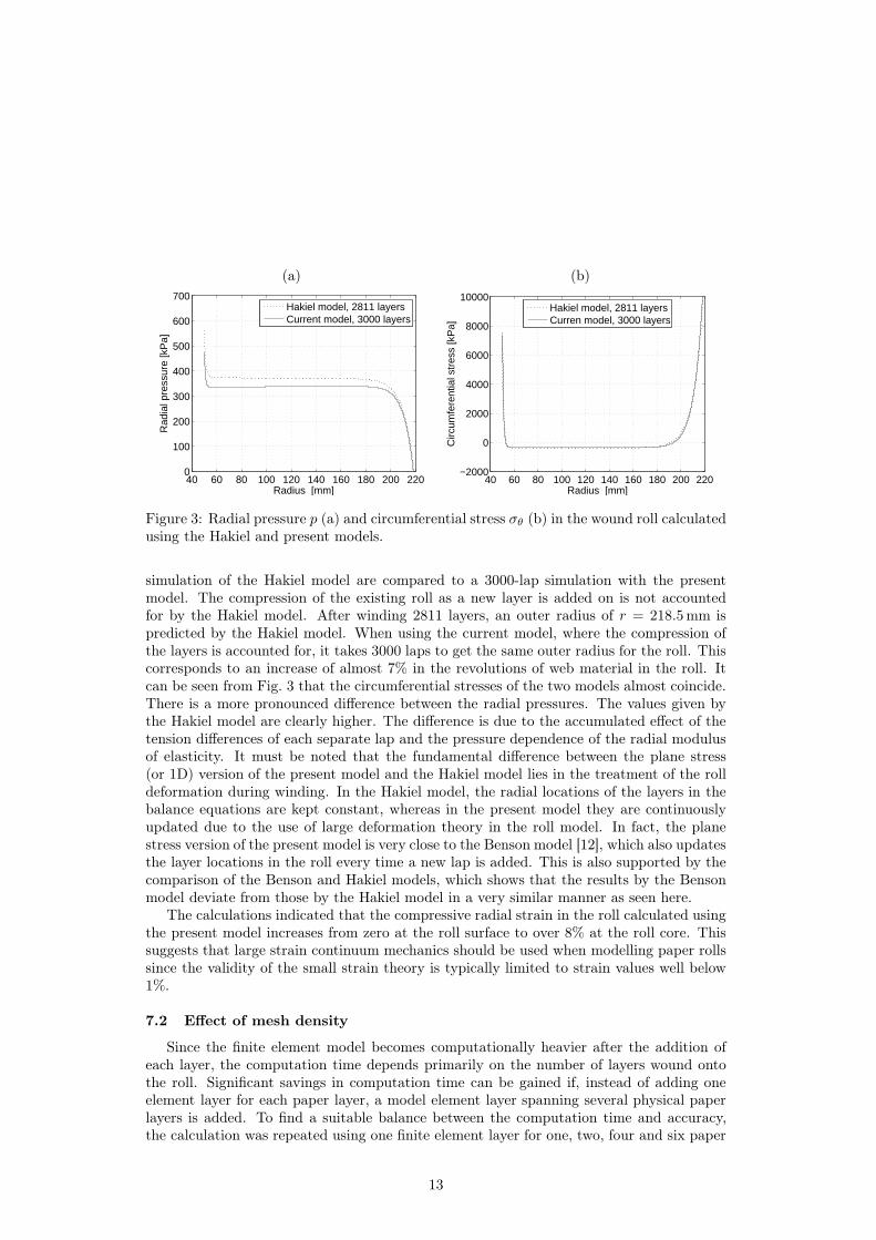
Figure 3: Radial pressure p (a) and circumferential stress σθ (b) in the wound roll calculatedusing the Hakiel and present models.
simulation of the Hakiel model are compared to a 3000-lap simulation with the presentmodel. The compression of the existing roll as a new layer is added on is not accountedfor by the Hakiel model. After winding 2811 layers, an outer radius of r = 218.5 mm ispredicted by the Hakiel model. When using the current model, where the compression ofthe layers is accounted for, it takes 3000 laps to get the same outer radius for the roll. Thiscorresponds to an increase of almost 7% in the revolutions of web material in the roll. Itcan be seen from Fig. 3 that the circumferential stresses of the two models almost coincide.There is a more pronounced difference between the radial pressures. The values given bythe Hakiel model are clearly higher. The difference is due to the accumulated effect of thetension differences of each separate lap and the pressure dependence of the radial modulusof elasticity. It must be noted that the fundamental difference between the plane stress(or 1D) version of the present model and the Hakiel model lies in the treatment of the rolldeformation during winding. In the Hakiel model, the radial locations of the layers in thebalance equations are kept constant, whereas in the present model they are continuouslyupdated due to the use of large deformation theory in the roll model. In fact, the planestress version of the present model is very close to the Benson model [12], which also updatesthe layer locations in the roll every time a new lap is added. This is also supported by thecomparison of the Benson and Hakiel models, which shows that the results by the Bensonmodel deviate from those by the Hakiel model in a very similar manner as seen here.
The calculations indicated that the compressive radial strain in the roll calculated usingthe present model increases from zero at the roll surface to over 8% at the roll core. Thissuggests that large strain continuum mechanics should be used when modelling paper rollssince the validity of the small strain theory is typically limited to strain values well below1%.
7.2 Effect of mesh density
Since the finite element model becomes computationally heavier after the addition ofeach layer, the computation time depends primarily on the number of layers wound ontothe roll. Significant savings in computation time can be gained if, instead of adding oneelement layer for each paper layer, a model element layer spanning several physical paperlayers is added. To find a suitable balance between the computation time and accuracy,the calculation was repeated using one finite element layer for one, two, four and six paper
13
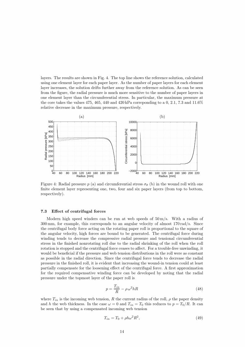
layers. The results are shown in Fig. 4. The top line shows the reference solution, calculatedusing one element layer for each paper layer. As the number of paper layers for each elementlayer increases, the solution drifts further away from the reference solution. As can be seenfrom the figure, the radial pressure is much more sensitive to the number of paper layers inone element layer than the circumferential stress. In particular, the maximum pressure atthe core takes the values 475, 465, 440 and 420 kPa correponding to a 0, 2.1, 7.3 and 11.6%relative decrease in the maximum pressure, respectively.
(a) (b)
40 60 80 100 120 140 160 180 200 2200
50
100
150
200
250
300
350
400
450
500
Radius [mm]
Rad
ial p
ress
ure
[kP
a]
40 60 80 100 120 140 160 180 200 220−2000
0
2000
4000
6000
8000
10000
Radius [mm]
Circ
umfe
rent
ial s
tres
s [k
Pa]
Figure 4: Radial pressure p (a) and circumferential stress σθ (b) in the wound roll with onefinite element layer representing one, two, four and six paper layers (from top to bottom,respectively).
7.3 Effect of centrifugal forces
Modern high speed winders can be run at web speeds of 50 m/s. With a radius of300 mm, for example, this corresponds to an angular velocity of almost 170 rad/s. Sincethe centrifugal body force acting on the rotating paper roll is proportional to the square ofthe angular velocity, high forces are bound to be generated. The centrifugal force duringwinding tends to decrease the compressive radial pressure and tensional circumferentialstress in the finished nonrotating roll due to the radial shrinking of the roll when the rollrotation is stopped and the centrifugal force ceases to affect. For a trouble-free unwinding, itwould be beneficial if the pressure and web tension distributions in the roll were as constantas possible in the radial direction. Since the centrifugal force tends to decrease the radialpressure in the finished roll, it is evident that increasing the wound-in tension could at leastpartially compensate for the loosening effect of the centrifugal force. A first approximationfor the required compensative winding force can be developed by noting that the radialpressure under the topmost layer of the paper roll is
p =Tin
R− ρω2hR (48)
where Tin is the incoming web tension, R the current radius of the roll, ρ the paper densityand h the web thickness. In the case ω = 0 and Tin = T0 this reduces to p = T0/R. It canbe seen that by using a compensated incoming web tension
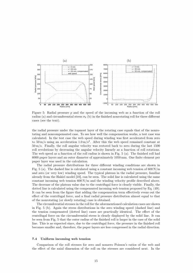
Figure 5: Radial pressure p and the speed of the incoming web as a function of the rollradius (a) and circumferential stress σθ (b) in the finished nonrotating roll for three differentcases (see the text).
the radial pressure under the topmost layer of the rotating case equals that of the nonro-tating and noncompensated case. To see how well the compensation works, a test case wascalculated. In the test case the web speed during winding was first accelerated from zeroto 50 m/s using an acceleration 1.0 m/s2. After this the web speed remained constant at50 m/s. Finally, the roll angular velocity was restored back to zero during the last 1500roll revolutions by decreasing the angular velocity linearly as a function of roll rotations.The web speed as a function of the roll radius is shown in Fig. 5 (a). The finished roll had6000 paper layers and an outer diameter of approximately 1050 mm. One finite element perpaper layer was used in the calculation.
The radial pressure distributions for three different winding conditions are shown inFig. 5 (a). The dashed line is calculated using a constant incoming web tension of 600 N/mand zero (or very low) winding speed. The typical plateau in the radial pressure, familiaralready from the Hakiel model [10], can be seen. The solid line is calculated using the sameconstant incoming web tension 600 N/m and the winding velocity profile described above.The decrease of the plateau value due to the centrifugal force is clearly visible. Finally, thedotted line is calculated using the compensated incoming web tension proposed by Eq. (49).It can be seen from the figure that adding the compensation term effectively evens out theeffect of the centrifugal force, and a final radial pressure distribution almost equal to thatof the nonrotating (or slowly rotating) case is obtained.
The circumferential stresses in the roll for the aforementioned calculation cases are shownin Fig. 5 (b). Again the stress distributions in the zero winding speed (dashed line) andthe tension compensated (dotted line) cases are practically identical. The effect of thecentrifugal force on the circumferential stress is clearly displayed by the solid line. It canbe seen from Fig. 5 that the outer radius of the finished roll is larger in the case of the solidline. This is as expected since, due to the centrifugal force, the pressure in the finished rollbecomes smaller and, therefore, the paper layers are less compressed in the radial direction.
7.4 Uniform incoming web tension
Comparison of the roll stresses for zero and nonzero Poisson’s ratios of the web andthe effect of the axial dimension of the roll on the stresses are considered next. In the
15
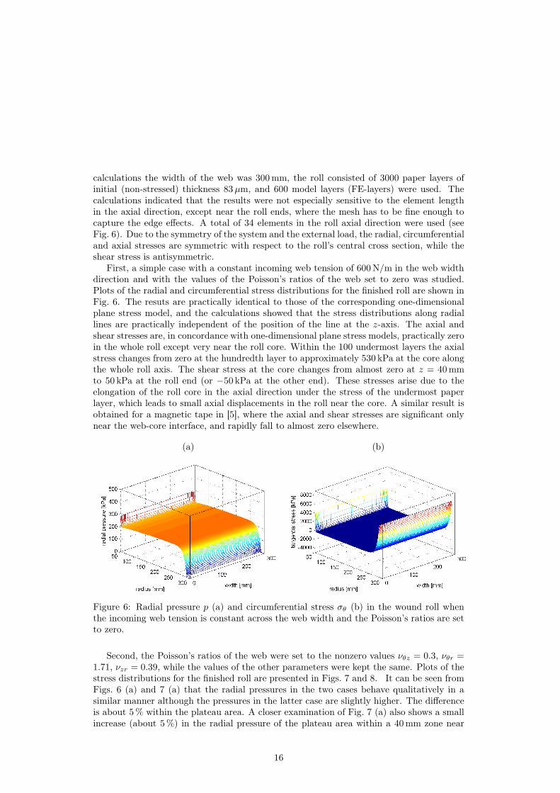
calculations the width of the web was 300 mm, the roll consisted of 3000 paper layers ofinitial (non-stressed) thickness 83µm, and 600 model layers (FE-layers) were used. Thecalculations indicated that the results were not especially sensitive to the element lengthin the axial direction, except near the roll ends, where the mesh has to be fine enough tocapture the edge effects. A total of 34 elements in the roll axial direction were used (seeFig. 6). Due to the symmetry of the system and the external load, the radial, circumferentialand axial stresses are symmetric with respect to the roll’s central cross section, while theshear stress is antisymmetric.
First, a simple case with a constant incoming web tension of 600 N/m in the web widthdirection and with the values of the Poisson’s ratios of the web set to zero was studied.Plots of the radial and circumferential stress distributions for the finished roll are shown inFig. 6. The resuts are practically identical to those of the corresponding one-dimensionalplane stress model, and the calculations showed that the stress distributions along radiallines are practically independent of the position of the line at the z-axis. The axial andshear stresses are, in concordance with one-dimensional plane stress models, practically zeroin the whole roll except very near the roll core. Within the 100 undermost layers the axialstress changes from zero at the hundredth layer to approximately 530 kPa at the core alongthe whole roll axis. The shear stress at the core changes from almost zero at z = 40 mmto 50 kPa at the roll end (or −50 kPa at the other end). These stresses arise due to theelongation of the roll core in the axial direction under the stress of the undermost paperlayer, which leads to small axial displacements in the roll near the core. A similar result isobtained for a magnetic tape in [5], where the axial and shear stresses are significant onlynear the web-core interface, and rapidly fall to almost zero elsewhere.
(a) (b)
Figure 6: Radial pressure p (a) and circumferential stress σθ (b) in the wound roll whenthe incoming web tension is constant across the web width and the Poisson’s ratios are setto zero.
Second, the Poisson’s ratios of the web were set to the nonzero values νθz = 0.3, νθr =1.71, νzr = 0.39, while the values of the other parameters were kept the same. Plots of thestress distributions for the finished roll are presented in Figs. 7 and 8. It can be seen fromFigs. 6 (a) and 7 (a) that the radial pressures in the two cases behave qualitatively in asimilar manner although the pressures in the latter case are slightly higher. The differenceis about 5 % within the plateau area. A closer examination of Fig. 7 (a) also shows a smallincrease (about 5 %) in the radial pressure of the plateau area within a 40 mm zone near
16
(a) (b)
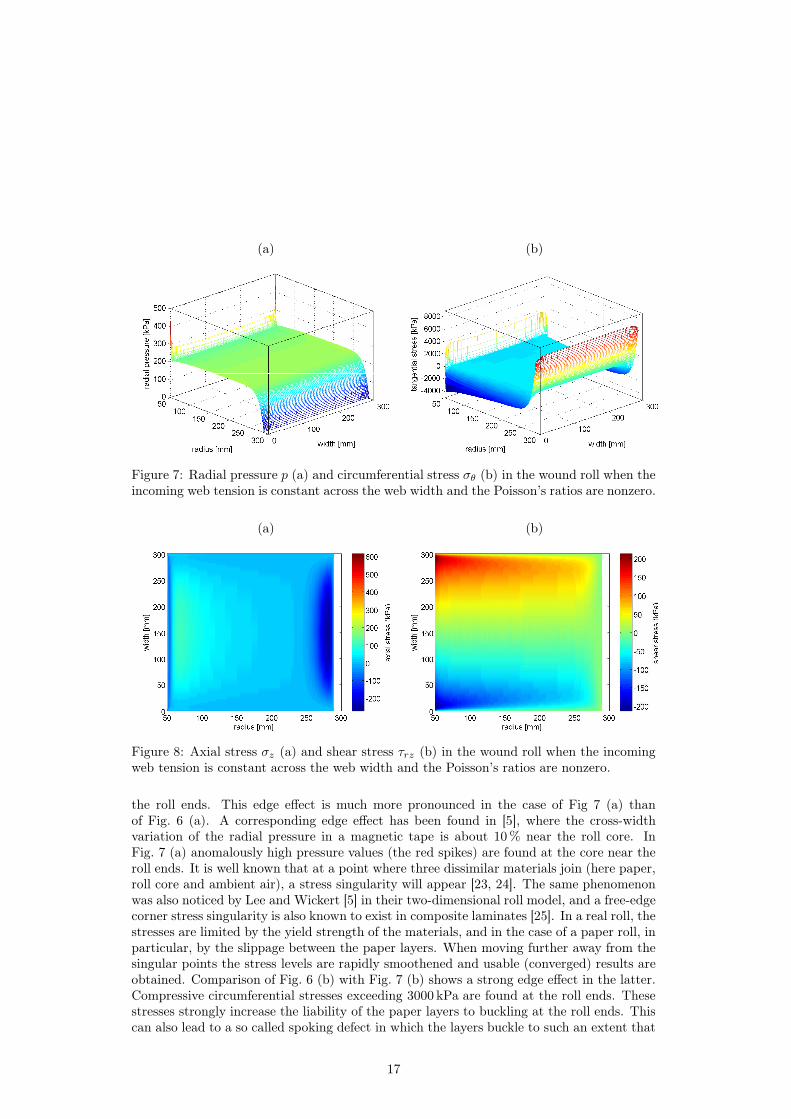
Figure 7: Radial pressure p (a) and circumferential stress σθ (b) in the wound roll when theincoming web tension is constant across the web width and the Poisson’s ratios are nonzero.
(a) (b)
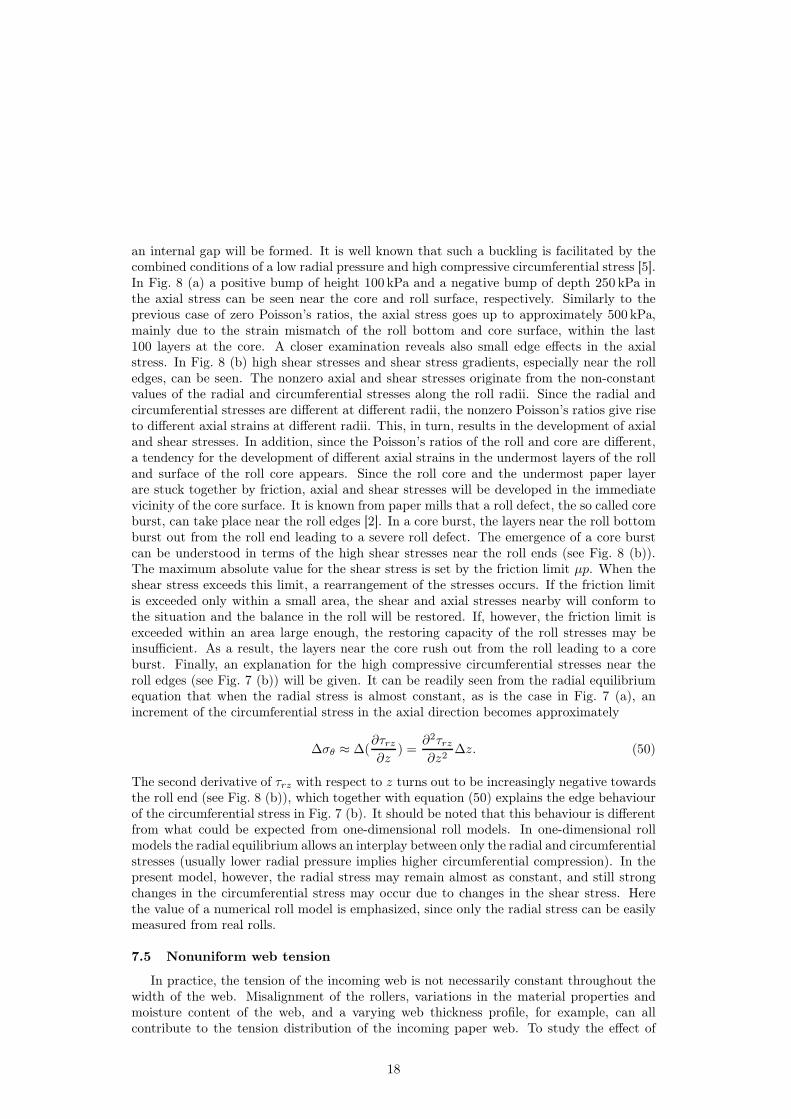
Figure 8: Axial stress σz (a) and shear stress τrz (b) in the wound roll when the incomingweb tension is constant across the web width and the Poisson’s ratios are nonzero.
the roll ends. This edge effect is much more pronounced in the case of Fig 7 (a) thanof Fig. 6 (a). A corresponding edge effect has been found in [5], where the cross-widthvariation of the radial pressure in a magnetic tape is about 10 % near the roll core. InFig. 7 (a) anomalously high pressure values (the red spikes) are found at the core near theroll ends. It is well known that at a point where three dissimilar materials join (here paper,roll core and ambient air), a stress singularity will appear [23, 24]. The same phenomenonwas also noticed by Lee and Wickert [5] in their two-dimensional roll model, and a free-edgecorner stress singularity is also known to exist in composite laminates [25]. In a real roll, thestresses are limited by the yield strength of the materials, and in the case of a paper roll, inparticular, by the slippage between the paper layers. When moving further away from thesingular points the stress levels are rapidly smoothened and usable (converged) results areobtained. Comparison of Fig. 6 (b) with Fig. 7 (b) shows a strong edge effect in the latter.Compressive circumferential stresses exceeding 3000 kPa are found at the roll ends. Thesestresses strongly increase the liability of the paper layers to buckling at the roll ends. Thiscan also lead to a so called spoking defect in which the layers buckle to such an extent that
17
an internal gap will be formed. It is well known that such a buckling is facilitated by thecombined conditions of a low radial pressure and high compressive circumferential stress [5].In Fig. 8 (a) a positive bump of height 100 kPa and a negative bump of depth 250 kPa inthe axial stress can be seen near the core and roll surface, respectively. Similarly to theprevious case of zero Poisson’s ratios, the axial stress goes up to approximately 500 kPa,mainly due to the strain mismatch of the roll bottom and core surface, within the last100 layers at the core. A closer examination reveals also small edge effects in the axialstress. In Fig. 8 (b) high shear stresses and shear stress gradients, especially near the rolledges, can be seen. The nonzero axial and shear stresses originate from the non-constantvalues of the radial and circumferential stresses along the roll radii. Since the radial andcircumferential stresses are different at different radii, the nonzero Poisson’s ratios give riseto different axial strains at different radii. This, in turn, results in the development of axialand shear stresses. In addition, since the Poisson’s ratios of the roll and core are different,a tendency for the development of different axial strains in the undermost layers of the rolland surface of the roll core appears. Since the roll core and the undermost paper layerare stuck together by friction, axial and shear stresses will be developed in the immediatevicinity of the core surface. It is known from paper mills that a roll defect, the so called coreburst, can take place near the roll edges [2]. In a core burst, the layers near the roll bottomburst out from the roll end leading to a severe roll defect. The emergence of a core burstcan be understood in terms of the high shear stresses near the roll ends (see Fig. 8 (b)).The maximum absolute value for the shear stress is set by the friction limit µp. When theshear stress exceeds this limit, a rearrangement of the stresses occurs. If the friction limitis exceeded only within a small area, the shear and axial stresses nearby will conform tothe situation and the balance in the roll will be restored. If, however, the friction limit isexceeded within an area large enough, the restoring capacity of the roll stresses may beinsufficient. As a result, the layers near the core rush out from the roll leading to a coreburst. Finally, an explanation for the high compressive circumferential stresses near theroll edges (see Fig. 7 (b)) will be given. It can be readily seen from the radial equilibriumequation that when the radial stress is almost constant, as is the case in Fig. 7 (a), anincrement of the circumferential stress in the axial direction becomes approximately
∆σθ ≈ ∆(∂τrz
∂z) =
∂2τrz
∂z2∆z. (50)
The second derivative of τrz with respect to z turns out to be increasingly negative towardsthe roll end (see Fig. 8 (b)), which together with equation (50) explains the edge behaviourof the circumferential stress in Fig. 7 (b). It should be noted that this behaviour is differentfrom what could be expected from one-dimensional roll models. In one-dimensional rollmodels the radial equilibrium allows an interplay between only the radial and circumferentialstresses (usually lower radial pressure implies higher circumferential compression). In thepresent model, however, the radial stress may remain almost as constant, and still strongchanges in the circumferential stress may occur due to changes in the shear stress. Herethe value of a numerical roll model is emphasized, since only the radial stress can be easilymeasured from real rolls.
7.5 Nonuniform web tension
In practice, the tension of the incoming web is not necessarily constant throughout thewidth of the web. Misalignment of the rollers, variations in the material properties andmoisture content of the web, and a varying web thickness profile, for example, can allcontribute to the tension distribution of the incoming paper web. To study the effect of
18
(a) (b)
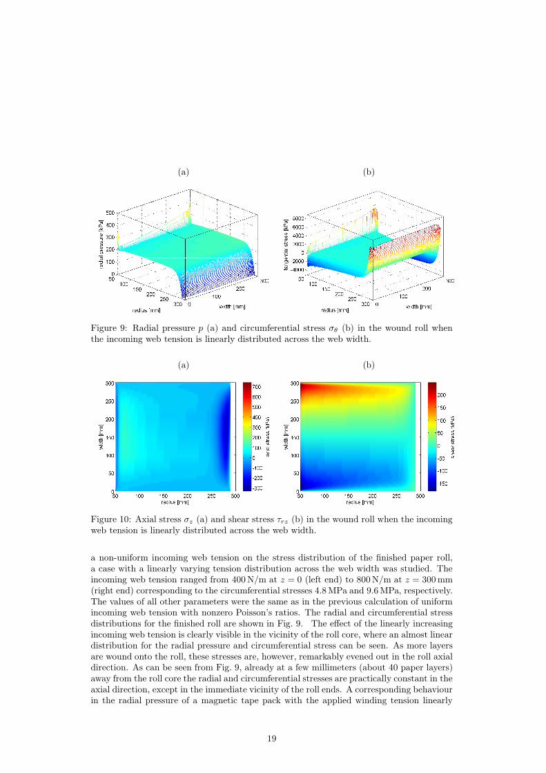
Figure 9: Radial pressure p (a) and circumferential stress σθ (b) in the wound roll whenthe incoming web tension is linearly distributed across the web width.
(a) (b)
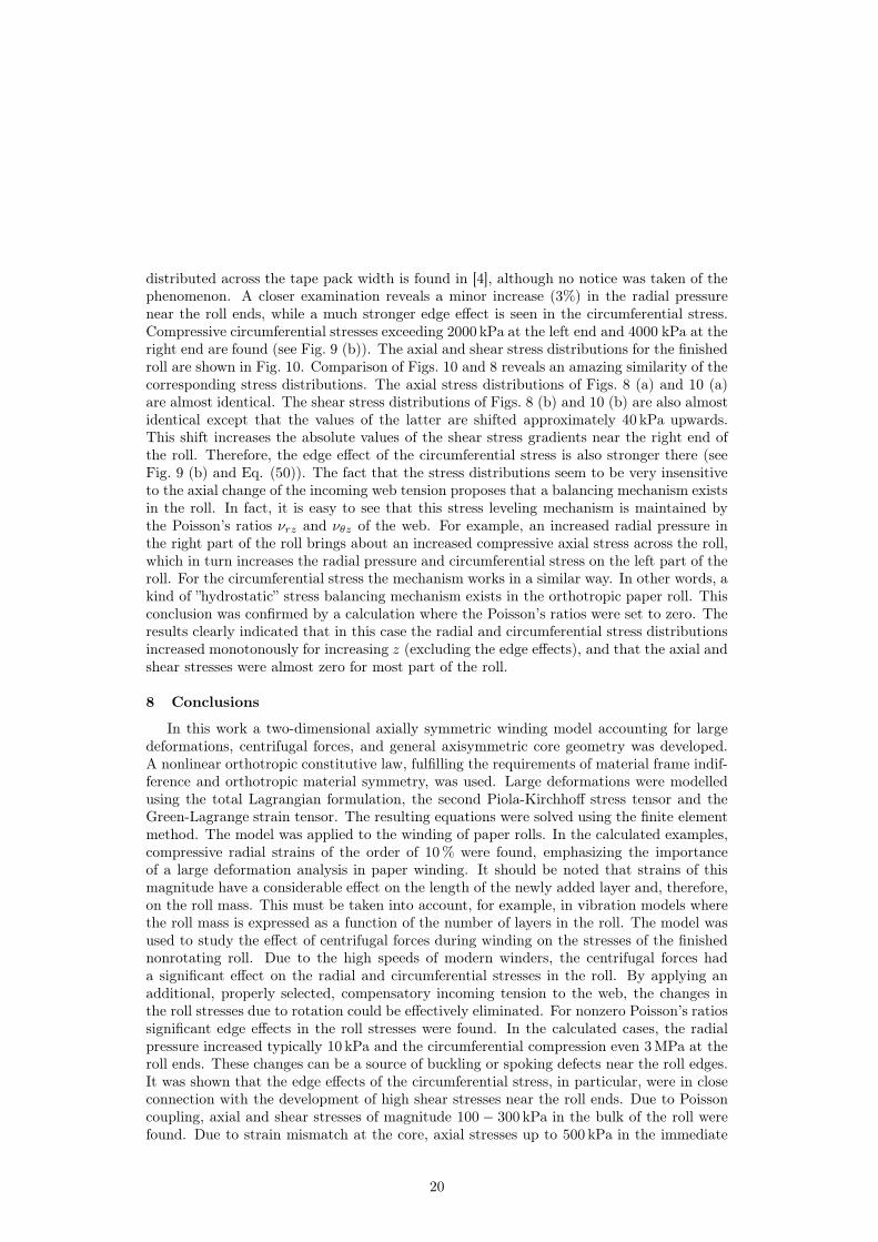
Figure 10: Axial stress σz (a) and shear stress τrz (b) in the wound roll when the incomingweb tension is linearly distributed across the web width.
a non-uniform incoming web tension on the stress distribution of the finished paper roll,a case with a linearly varying tension distribution across the web width was studied. Theincoming web tension ranged from 400 N/m at z = 0 (left end) to 800 N/m at z = 300 mm(right end) corresponding to the circumferential stresses 4.8 MPa and 9.6 MPa, respectively.The values of all other parameters were the same as in the previous calculation of uniformincoming web tension with nonzero Poisson’s ratios. The radial and circumferential stressdistributions for the finished roll are shown in Fig. 9. The effect of the linearly increasingincoming web tension is clearly visible in the vicinity of the roll core, where an almost lineardistribution for the radial pressure and circumferential stress can be seen. As more layersare wound onto the roll, these stresses are, however, remarkably evened out in the roll axialdirection. As can be seen from Fig. 9, already at a few millimeters (about 40 paper layers)away from the roll core the radial and circumferential stresses are practically constant in theaxial direction, except in the immediate vicinity of the roll ends. A corresponding behaviourin the radial pressure of a magnetic tape pack with the applied winding tension linearly
19
distributed across the tape pack width is found in [4], although no notice was taken of thephenomenon. A closer examination reveals a minor increase (3%) in the radial pressurenear the roll ends, while a much stronger edge effect is seen in the circumferential stress.Compressive circumferential stresses exceeding 2000 kPa at the left end and 4000 kPa at theright end are found (see Fig. 9 (b)). The axial and shear stress distributions for the finishedroll are shown in Fig. 10. Comparison of Figs. 10 and 8 reveals an amazing similarity of thecorresponding stress distributions. The axial stress distributions of Figs. 8 (a) and 10 (a)are almost identical. The shear stress distributions of Figs. 8 (b) and 10 (b) are also almostidentical except that the values of the latter are shifted approximately 40 kPa upwards.This shift increases the absolute values of the shear stress gradients near the right end ofthe roll. Therefore, the edge effect of the circumferential stress is also stronger there (seeFig. 9 (b) and Eq. (50)). The fact that the stress distributions seem to be very insensitiveto the axial change of the incoming web tension proposes that a balancing mechanism existsin the roll. In fact, it is easy to see that this stress leveling mechanism is maintained bythe Poisson’s ratios νrz and νθz of the web. For example, an increased radial pressure inthe right part of the roll brings about an increased compressive axial stress across the roll,which in turn increases the radial pressure and circumferential stress on the left part of theroll. For the circumferential stress the mechanism works in a similar way. In other words, akind of ”hydrostatic” stress balancing mechanism exists in the orthotropic paper roll. Thisconclusion was confirmed by a calculation where the Poisson’s ratios were set to zero. Theresults clearly indicated that in this case the radial and circumferential stress distributionsincreased monotonously for increasing z (excluding the edge effects), and that the axial andshear stresses were almost zero for most part of the roll.
8 Conclusions
In this work a two-dimensional axially symmetric winding model accounting for largedeformations, centrifugal forces, and general axisymmetric core geometry was developed.A nonlinear orthotropic constitutive law, fulfilling the requirements of material frame indif-ference and orthotropic material symmetry, was used. Large deformations were modelledusing the total Lagrangian formulation, the second Piola-Kirchhoff stress tensor and theGreen-Lagrange strain tensor. The resulting equations were solved using the finite elementmethod. The model was applied to the winding of paper rolls. In the calculated examples,compressive radial strains of the order of 10 % were found, emphasizing the importanceof a large deformation analysis in paper winding. It should be noted that strains of thismagnitude have a considerable effect on the length of the newly added layer and, therefore,on the roll mass. This must be taken into account, for example, in vibration models wherethe roll mass is expressed as a function of the number of layers in the roll. The model wasused to study the effect of centrifugal forces during winding on the stresses of the finishednonrotating roll. Due to the high speeds of modern winders, the centrifugal forces hada significant effect on the radial and circumferential stresses in the roll. By applying anadditional, properly selected, compensatory incoming tension to the web, the changes inthe roll stresses due to rotation could be effectively eliminated. For nonzero Poisson’s ratiossignificant edge effects in the roll stresses were found. In the calculated cases, the radialpressure increased typically 10 kPa and the circumferential compression even 3 MPa at theroll ends. These changes can be a source of buckling or spoking defects near the roll edges.It was shown that the edge effects of the circumferential stress, in particular, were in closeconnection with the development of high shear stresses near the roll ends. Due to Poissoncoupling, axial and shear stresses of magnitude 100 − 300 kPa in the bulk of the roll werefound. Due to strain mismatch at the core, axial stresses up to 500 kPa in the immediate
20
vicinity of the roll core emerged. High shear stress gradients (up to 40 kPa/mm) were foundnear the roll ends, and especially, near the core. It was pointed out that these gradientsare strongly contributing to the appearance of core bursts, a class of severe roll defects. Itis evident that by properly selecting the elastic moduli of the core, the high stresses nearthe core could be at least partially eliminated. A novel stress leveling phenomenon in theroll was discovered. Namely, for a linearly distributed incoming web tension across the webwidth, almost width-independent radial and circumferential stress distributions were found.This leveling off could be attributed to the Poisson’s ratios of the web. In future work, theeffect of width-wise variation of the elastic moduli and thickness of the web on the finishedroll should be studied, since these variations occur in real paper webs frequently.
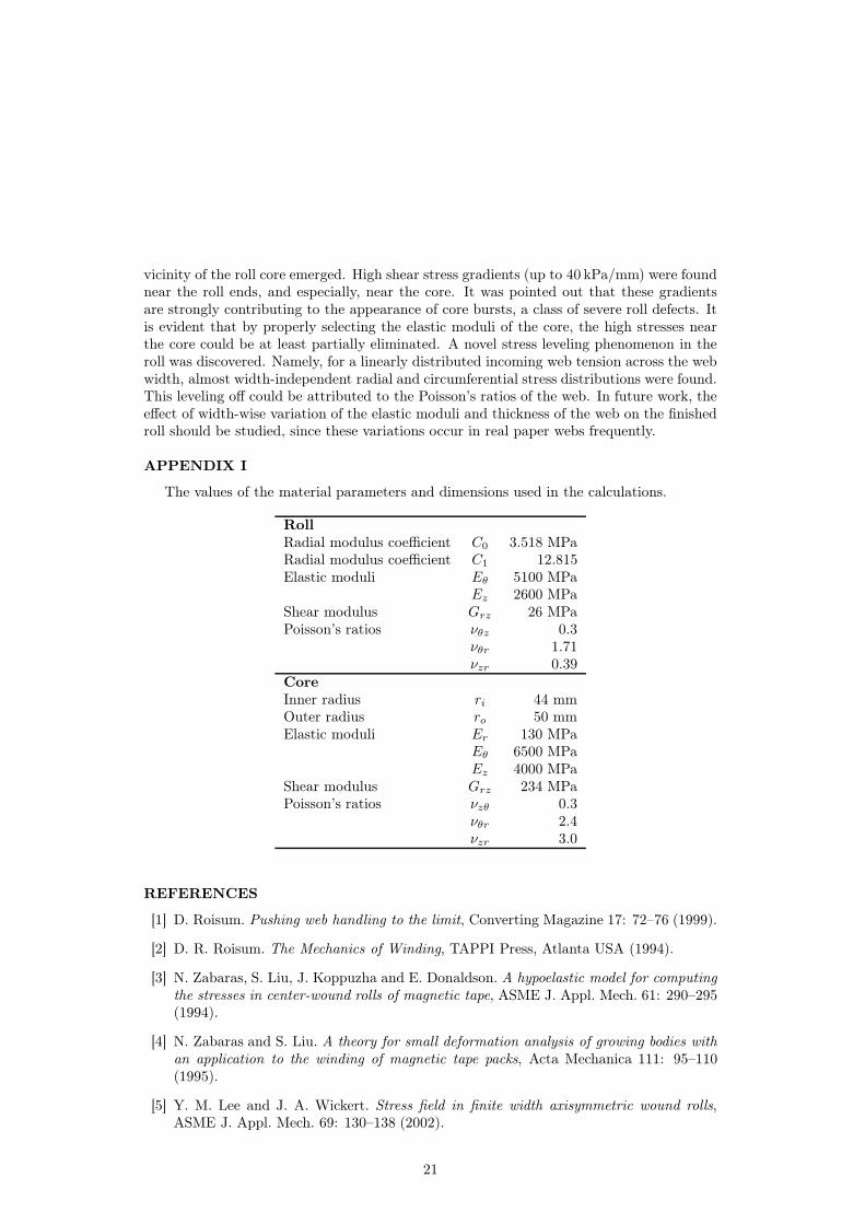
APPENDIX I
The values of the material parameters and dimensions used in the calculations.
Ez 2600 MPaShear modulus Grz 26 MPaPoisson’s ratios νθz 0.3
νθr 1.71νzr 0.39
Core
Inner radius ri 44 mmOuter radius ro 50 mmElastic moduli Er 130 MPa
Eθ 6500 MPaEz 4000 MPa
Shear modulus Grz 234 MPaPoisson’s ratios νzθ 0.3
νθr 2.4νzr 3.0
REFERENCES
[1] D. Roisum. Pushing web handling to the limit, Converting Magazine 17: 72–76 (1999).
[2] D. R. Roisum. The Mechanics of Winding, TAPPI Press, Atlanta USA (1994).
[3] N. Zabaras, S. Liu, J. Koppuzha and E. Donaldson. A hypoelastic model for computing
the stresses in center-wound rolls of magnetic tape, ASME J. Appl. Mech. 61: 290–295(1994).
[4] N. Zabaras and S. Liu. A theory for small deformation analysis of growing bodies with
an application to the winding of magnetic tape packs, Acta Mechanica 111: 95–110(1995).
[5] Y. M. Lee and J. A. Wickert. Stress field in finite width axisymmetric wound rolls,ASME J. Appl. Mech. 69: 130–138 (2002).
21
[6] Y. M. Lee and J. A. Wickert. Width-wise variation of magnetic tape pack stresses,ASME J. Appl. Mech. 69: 358–369 (2002).
[7] H. C. Altmann. Formulas for computing the stresses in center-wound rolls, TAPPIJournal 51: 176–179 (1968).
[8] H. P. Yagoda. Resolution of a core problem in wound rolls, ASME J. Appl. Mech. 47:847–854 (1980).
[9] D. Connolly and D. J. Winarski. Stress analysis of wound magnetic tape, ASLE Tri-bology and Mechanics of Magnetic Storage Media, Special Publication Vol:16. ASLE,172–182 (1984).
[10] Z. Hakiel. Nonlinear model for wound roll stresses, TAPPI Journal 70: 113–117 (1987).
[11] M. S. Willet and W. L. Poesch. Determining the stress distributions in wound reels of
magnetic tape using a nonlinear finite-difference approach, ASME J. Appl. Mech. 55:365–371 (1988).
[12] R. C. Benson. A nonlinear wound roll model allowing for large deformation, ASMEJ. Appl. Mech. 62: 853–859 (1995).
[13] H. Tramposch. Relaxation of internal forces in a wound reel of magnetic tape, ASMEJ. Appl. Mech. 32: 865–873 (1965).
[14] H. Tramposch. Anisotropic relaxation of internal forces in a wound reel of magnetic
tape, ASME J. Appl. Mech. 34: 888–894 (1967).
[15] J. C. Heinrich, D. Connolly and B. Bhushan. Axisymmetric, finite element analysis
of stress relaxation in wound magnetic tapes, ASLE Trans. 29: 75–84 (1986).
[16] W. R. Qualls and J. K. Good. An orthotropic viscoelastic winding model including a
nonlinear radial stiffness, ASME J. Appl. Mech. 64: 201–208 (1997).
[17] S. Li and J. Cao. A hybrid approach for quantifying the winding process and material
effects on sheet coil deformation, ASME J. Eng. Mater. Tech. 126: 303–313 (2004).
[18] J. E. Olsen. On the effect of centrifugal force on winding, TAPPI Journal 78: 191–195(1995).
[19] J.K. Good, J.D. Pfeiffer and R.M. Giachetto. Losses in wound-on tension in the
centerwinding of wound rolls, Web Handling, ASME AMD-149, ASME, New York,1–12 (1992).
[20] A. J. M. Spencer. The formulation of constitutive equation for anisotropic solids,In: J.–P. Boehler (ed.) Mechanical behaviour of anisotropic solids, Proceedings of theEuromech Colloquium 115, June 1979, 19–22. Martinus Nijhoff publishers, Hague,Netherlands, 2–26 (1982).
[21] J. D. Pfeiffer. Measurement of the K2 factor for paper, Tappi Journal 64: 105–106(1981).
[22] M. Ilomäki. Application of fracture mechanics in analyzing delemination of cyclically
loaded paperboard core, Doctoral thesis, University of Oulu, Finland (2004).
22
[23] D. B. Bogy. On the problem of edge-bonded elastic quarter-planes loaded at the bound-
ary, Int. J. Solids Struct. 6: 1287–1313 (1970).
[24] E. S. Folias. On the stress singularities at the intersection of a cylindrical inclusion
with the free surface of a plate, Int. J. Frac. 39: 25–34 (1989).
[25] S. S. Wang and I. Choi. Boundary-Layer Effects in Composite Laminates: Part 1-
Free-Edge Stress Singularities, ASME J. Appl. Mech. 49: 541–548 (1982).


![Penetration Height and Onset of Asymmetric Behaviour of … · 2014. 12. 18. · fountains as either axisymmetric and two-dimensional or asymmetric and three-dimensional. Both [1]](https://static.documents.pub/doc/80x56/60b2b8650ed50d29e37242ca/penetration-height-and-onset-of-asymmetric-behaviour-of-2014-12-18-fountains.jpg)


