Page 1
International Journal of Heat and Mass Transfer 48 (2005) 928–940
www.elsevier.com/locate/ijhmt
Two-phase flow in high-heat-flux micro-channelheat sink for refrigeration cooling applications:
Part I––pressure drop characteristics
Jaeseon Lee, Issam Mudawar *
Boiling and Two-Phase Flow Laboratory, School of Mechanical Engineering, Purdue University, West Lafayette, IN 47907 1288, USA
Received 12 July 2004; received in revised form 10 September 2004
Available online 8 December 2004
Abstract
Two-phase pressure drop was measured across a micro-channel heat sink that served as an evaporator in a refrig-
eration cycle. The micro-channels were formed by machining 231lm wide · 713lm deep grooves into the surface of a
copper block. Experiments were performed with refrigerant R134a that spanned the following conditions: inlet pressure
of Pin = 1.44–6.60bar, mass velocity of G = 127–654kg/m2s, inlet quality of xe,in = 0.001–0.25, outlet quality of
xe,out = 0.49–superheat, and heat flux of q00 = 31.6–93.8W/cm2. Predictions of the homogeneous equilibrium flow model
and prior separated flow models and correlations yielded relatively poor predictions of pressure drop. A new correlation
scheme is suggested that incorporates the effect of liquid viscosity and surface tension in the separated flow model�s two-phase pressure drop multiplier. This scheme shows excellent agreement with the R134a data as well as previous micro-
channel water data. An important practical finding from this study is that the throttling valve in a refrigeration cycle
offers significant stiffening to the system, suppressing the large pressure oscillations common to micro-channel heat
sinks.
� 2004 Elsevier Ltd. All rights reserved.
Keywords: Micro-channels; Flow boiling; Refrigeration; Pressure drop
1. Introduction
Two-phase pressure drop has been the subject of
extensive research spanning many decades. Starting in
the 1940s, researchers were concerned with developing
predictive pressure drop models and correlations for
mostly traditional industries such as steam and nuclear
0017-9310/$ - see front matter � 2004 Elsevier Ltd. All rights reserv
doi:10.1016/j.ijheatmasstransfer.2004.09.018
* Corresponding author. Tel.: +1 765 494 5705; fax: +1 765
494 0539.
E-mail address: [email protected] (I. Mudawar).
power generation, chemical and petroleum, desalination,
refrigeration and air conditioning, etc.
With the recent emergence of new applications
demanding high-heat-flux dissipation from small areas,
the validity of popular pressure drop models and corre-
lations became an open question. These new cooling de-
mands were brought about mostly by the remarkable
technological advances in the electronics industry. Since
a key measure of improvement in device performance is
the ability to integrate the largest number of electronic
components in a given surface area, those advances have
yielded unprecedented increases in device heat
dissipation.
ed.
Page 2
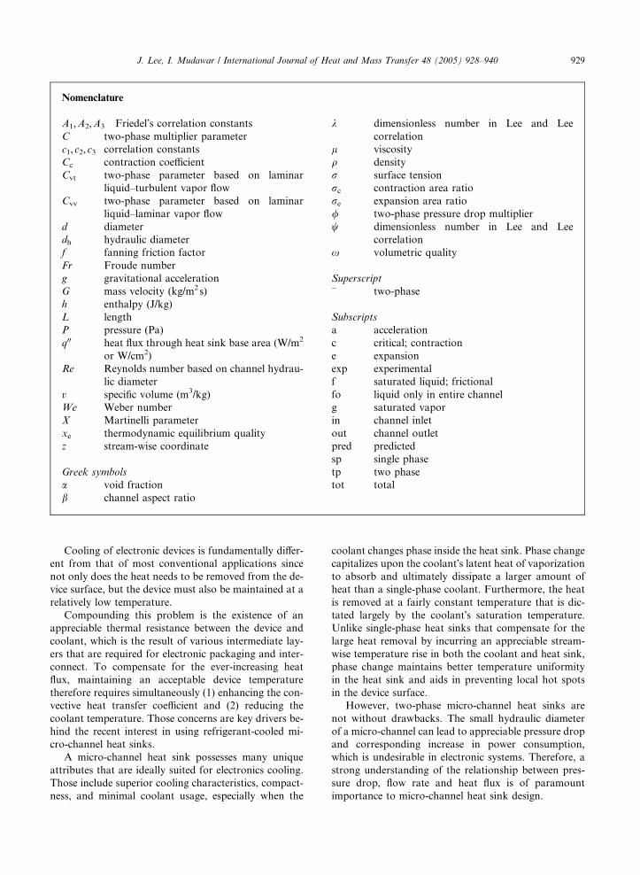
Nomenclature
A1,A2,A3 Friedel�s correlation constants
C two-phase multiplier parameter
c1,c2,c3 correlation constants
Cc contraction coefficient
Cvt two-phase parameter based on laminar
liquid–turbulent vapor flow
Cvv two-phase parameter based on laminar
liquid–laminar vapor flow
d diameter
dh hydraulic diameter
f fanning friction factor
Fr Froude number
g gravitational acceleration
G mass velocity (kg/m2s)
h enthalpy (J/kg)
L length
P pressure (Pa)
q00 heat flux through heat sink base area (W/m2
or W/cm2)
Re Reynolds number based on channel hydrau-
lic diameter
v specific volume (m3/kg)
We Weber number
X Martinelli parameter
xe thermodynamic equilibrium quality
z stream-wise coordinate
Greek symbols
a void fraction
b channel aspect ratio
k dimensionless number in Lee and Lee
correlation
l viscosity
q density
r surface tension
rc contraction area ratio
re expansion area ratio
/ two-phase pressure drop multiplier
w dimensionless number in Lee and Lee
correlation
x volumetric quality
Superscript
� two-phase
Subscripts
a acceleration
c critical; contraction
e expansion
exp experimental
f saturated liquid; frictional
fo liquid only in entire channel
g saturated vapor
in channel inlet
out channel outlet
pred predicted
sp single phase
tp two phase
tot total
J. Lee, I. Mudawar / International Journal of Heat and Mass Transfer 48 (2005) 928–940 929
Cooling of electronic devices is fundamentally differ-
ent from that of most conventional applications since
not only does the heat needs to be removed from the de-
vice surface, but the device must also be maintained at a
relatively low temperature.
Compounding this problem is the existence of an
appreciable thermal resistance between the device and
coolant, which is the result of various intermediate lay-
ers that are required for electronic packaging and inter-
connect. To compensate for the ever-increasing heat
flux, maintaining an acceptable device temperature
therefore requires simultaneously (1) enhancing the con-
vective heat transfer coefficient and (2) reducing the
coolant temperature. Those concerns are key drivers be-
hind the recent interest in using refrigerant-cooled mi-
cro-channel heat sinks.
A micro-channel heat sink possesses many unique
attributes that are ideally suited for electronics cooling.
Those include superior cooling characteristics, compact-
ness, and minimal coolant usage, especially when the
coolant changes phase inside the heat sink. Phase change
capitalizes upon the coolant�s latent heat of vaporizationto absorb and ultimately dissipate a larger amount of
heat than a single-phase coolant. Furthermore, the heat
is removed at a fairly constant temperature that is dic-
tated largely by the coolant�s saturation temperature.
Unlike single-phase heat sinks that compensate for the
large heat removal by incurring an appreciable stream-
wise temperature rise in both the coolant and heat sink,
phase change maintains better temperature uniformity
in the heat sink and aids in preventing local hot spots
in the device surface.
However, two-phase micro-channel heat sinks are
not without drawbacks. The small hydraulic diameter
of a micro-channel can lead to appreciable pressure drop
and corresponding increase in power consumption,
which is undesirable in electronic systems. Therefore, a
strong understanding of the relationship between pres-
sure drop, flow rate and heat flux is of paramount
importance to micro-channel heat sink design.
Page 3
930 J. Lee, I. Mudawar / International Journal of Heat and Mass Transfer 48 (2005) 928–940
Many of the two-phase pressure drop models and
correlations used in industry today stem from the pio-
neering Lockhart–Martinelli [1] formulation, which has
been modified by many investigators in pursuit of better
predictions for macro-channels (e.g., Friedel [2], Chis-
holm [3]). However, recent studies have shown this for-
mulation produces poor predictions when attempted
with small channels, suggesting different flow character-
istic must be prevalent in the smaller channels.
Bowers and Mudawar [4] were the first to provide a
systematic assessment of the unique attributes of pres-
sure drop across micro-channel heat sinks. To examine
the influence of hydraulic diameter, they compared the
pressure drop for refrigerant R113 in both mini-channel
(d = 2.54mm) and micro-channel (d = 510lm) heat
sinks. Using the homogeneous equilibrium model, they
pointed out the serious drawbacks of a very small
hydraulic diameter caused by the excessive pressure drop
associated with acceleration of the two-phase mixture.
Mishima and Hibiki [5] modified the two-phase multi-
plier in the Lockhart–Martinelli with a new parameter
to improve pressure drop prediction for air–water flow
in vertical capillary tubes with diameters of d = 1–
4mm. Triplett et al. [6] investigated air–water flow in
small circular tubes (d = 1.1,1.45mm) and triangular
channels (dh = 1.09,1.49mm). The homogeneous equi-
librium model showed good predictions for the bubbly
and slug flow regimes but not the annular, and the Fri-
edel�s correlation (based on the separated flow model)
was less accurate than the homogeneous model. Tran
et al. [7] investigated two-phase flow of refrigerants
R134a, R12, and R113 in small circular channels
(d = 2.46,2.92mm) and a rectangular channel (dh =
2.40mm). Most separated flow models predicted pres-
sure drop values that were smaller than measured.
Therefore, they developed a new correlation to better ac-
count for the effects of surface tension and channel
diameter. Lee and Lee [8] modified the Lockhart–Marti-
nelli two-phase multiplier with a new parameter they
correlated form their own data for air–water flow in
rectangular channels (dh = 0.784,6.67mm). Zhang and
Webb [9] investigated two-phase flow of refrigerants
R134a, R22 and R404a in parallel circular channels
(d = 2.13mm) and recommended a new pressure drop
correlation based on the separated flow model. Kawa-
hara et al. [10] investigated water–nitrogen flow in a
100lm circular tube. They reported the homogeneous
flow model generally overpredicted pressure drop data,
while the separated flow model using a modified two-
phase flow multiplier showed better agreement.
Recently, Qu and Mudawar investigated the funda-
mental features of two-phase flow and heat transfer in
a water-cooled micro-channel heat sink [11,12]. Their
work culminated in a comprehensive theoretical model
which yielded good predictions of two-phase pressure
drop and heat transfer.
The present study is an extension of recent efforts by
Mudawar and co-workers to develop a comprehensive
method for determining micro-channel heat sink pres-
sure drop for coolants with drastically different thermo-
physical properties. New experiments were performed
with R134a that were complimented by flow visualiza-
tion. The heat sink was incorporated as an evaporator
in a refrigeration cycle in an effort to achieve the afore-
mentioned goals of high-flux removal while maintaining
low surface temperatures. Using both the new R134a
pressure drop data as well as Qu and Mudawar�s earlierwater data, a new correlation scheme is recommended
for two-phase pressure drop determination. This scheme
is shown to yield far better accuracy than prior macro-
channel and small channel correlations. Also discussed
in this paper are various unique features of pressure
drop in micro-channel evaporators and the suitability
refrigerant-cooled heat sinks to electronic cooling
applications.
2. Experimental methods
2.1. Apparatus and measurement techniques
Fig. 1 shows the test facility constructed for this
study resembled a conventional refrigeration cycle save
for using the micro-channel evaporator. The working
fluid used in this study, R134a, is an environmentally
friendly non-ozone-depleting HFC refrigerant with
overwhelming popularity in most domestic refrigeration
and air conditioning applications. Vapor compression
was achieved with a DC rotary compressor whose power
was determined from its measured current and voltage
input. Heat was rejected from the loop via a conven-
tional fin-tube condenser fitted with a cross-flow fan.
The fan speed was controlled with a variable voltage
transformer that helped modulate the subcooling of
the two-phase mixture exiting the condenser. Throttling
from high to low pressure was achieved by a manual
metering valve situated upstream of the micro-channel
evaporator test section.
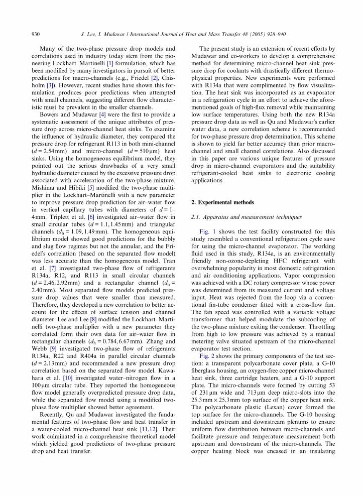
Fig. 2 shows the primary components of the test sec-
tion: a transparent polycarbonate cover plate, a G-10
fiberglass housing, an oxygen-free copper micro-channel
heat sink, three cartridge heaters, and a G-10 support
plate. The micro-channels were formed by cutting 53
of 231lm wide and 713lm deep micro-slots into the
25.3mm · 25.3mm top surface of the copper heat sink.
The polycarbonate plastic (Lexan) cover formed the
top surface for the micro-channels. The G-10 housing
included upstream and downstream plenums to ensure
uniform flow distribution between micro-channels and
facilitate pressure and temperature measurement both
upstream and downstream of the micro-channels. The
copper heating block was encased in an insulating
Page 4
Fig. 1. Schematic of test loop.
Fig. 2. Construction of micro-channel evaporator test section.
J. Lee, I. Mudawar / International Journal of Heat and Mass Transfer 48 (2005) 928–940 931
blanket to reduce heat loss to the ambient. Heat was
supplied by the cartridge heaters that were embedded
beneath the micro-channels; these heaters were powered
by a variable voltage transformer.
Two type-T thermocouples were inserted in the inlet
and outlet plenums to measure fluid temperature at
those locations. Another type-K thermocouple was in-
serted in the copper block halfway along the micro-
channels. An absolute pressure transducer measured
the inlet plenum pressure and a differential pressure
transducer the pressure drop between the inlet and
outlet plenums. Additional type-T thermocouples and
Page 5
932 J. Lee, I. Mudawar / International Journal of Heat and Mass Transfer 48 (2005) 928–940
absolute pressure transducers were located both down-
stream of the compressor and upstream of the throttling
valve. A precision power meter connected to the car-
tridge heaters� variable voltage transformer was used
to measure heat input to the coolant in the evaporator.
All thermocouple and pressure transducer measurement
signals were transferred to an NI-SCXI signal condi-
tioner interfaced to data acquisition PC. The flow rate
of R134a entering the micro-channel evaporator was
measured by a glass rotameter situated downstream of
the condenser, which also served as a visual indicator
of liquid state at that location.
The rotameter provided better than 2% accuracy in
flow rate measurement. Errors in the pressure transducer
and thermocouple measurements were less than 0.5%
and ±0.3 �C, respectively. Heat loss from the heat sink
was estimated at less than 4% of the electrical power
input.
2.1.1. Determination of operating conditions
The refrigerant left the compressor in superheated
vapor state and was returned to subcooled liquid after
passing through the condenser. Afterwards, the liquid
was converted to a two-phase mixture by flashing across
the throttling valve. The two-phase mixture entered
the evaporator and was converted to superheated
vapor before entering the compressor and repeating
the cycle.
The mass flow rate of refrigerant entering the evapo-
rator was calculated as the product of volumetric flow
rate of liquid measured by the rotameter, and the density
of liquid calculated from the temperature and pressure
measurements. Since the throttling process is isenthal-
pic, the evaporator inlet enthalpy was determined from
the liquid temperature and pressure measured down-
stream of the condenser. Using this enthalpy value and
the evaporator measured inlet temperature or pressure
provided accurate determination of the evaporator�s in-let quality, xe,in.
Experimental data were acquired over the following
range of parameters: inlet pressure of Pin = 1.44–
6.60bar, mass velocity of G = 127–654kg/m2s, inlet
quality of xe,in = 0.001–0.25, outlet quality of
xe,out = 0.49–superheat, and heat flux of q00 = 31.6–
93.8W/cm2.
3. Results and discussion
3.1. Pressure drop determination
The evaporator pressure drop measured by the differ-
ential pressure transducer includes the sudden contrac-
tion loss at the micro-channel inlet and sudden
expansion recovery at the outlet. Within the micro-chan-
nels, the two-phase pressure drop consists of frictional
and accelerational components. Should the two-phase
mixture undergo complete conversion to vapor within
the micro-channel, a pressure drop corresponding to
pure vapor flow would also be incurred in the down-
stream region of the micro-channels. In this case, the to-
tal pressure drop between the upstream and downstream
plenums can be expressed as
DP tot ¼ DP c þ ðDP f þ DP aÞtp þ DP sp;g � DP e: ð1Þ
The contraction pressure loss and expansion recovery
were determined from the following relations [2]:
DP c ¼G2vf2
1
Cc
� 1
� �2
þ 1� 1
r2c
� �" #1þ vfgxe;in
vf
� �ð2Þ
and
DP e ¼ G2reð1� reÞvf 1þ vfgxe;outvf
� �: ð3Þ
The contraction coefficient Cc is a function of the
contraction ratio rc [2]. If the refrigerant exits the
micro-channels as pure vapor, the exit quality xe,out in
the pressure recovery term should be set equal to unity.
When the refrigerant is completely converted into
vapor within the micro-channel, the pressure drop for
the vapor flow region can be determined form the
following relation [13,14]:
DP sp;g ¼2Lsp
dh
fsp;gG2vg; ð4Þ
where
fsp;gReg ¼ 24½1� 1:3553b þ 1:9467b2 � 1:7012b3
þ 0:9564b4 � 0:2537b5� for Reg < 2000;
ð5aÞ
fsp;g ¼ 0:079Re�0:25g for 2000 < Reg < 20; 000; ð5bÞ
and
fsp;g ¼ 0:046Re�0:2g for 20; 000 < Reg: ð5cÞ
The remaining contributions to the evaporator pres-
sure drop are the two-phase frictional and accelerational
components. These are discussed in the next section.
3.2. Two-phase pressure drop models
3.2.1. Homogeneous equilibrium model (HEM)
The homogeneous equilibrium model is based on the
assumption that the two-phase mixture behaves as a
pseudo single-phase fluid with mean properties that are
weighted relative to vapor and liquid content, and that
only latent heat may be exchanged between the phases.
Property variations resulting from pressure changes
along the micro-channel result in complicating terms
that account for kinetic energy changes, flashing, and
Page 6
J. Lee, I. Mudawar / International Journal of Heat and Mass Transfer 48 (2005) 928–940 933
compressibility [4]. The resulting pressure gradient may
be expressed as
� dPdz
� �tp
¼
2f tp
dh
G2ðvf þ xevfgÞ þ4q00Gvfg
dh½hfg þ G2vfgfxevg þ ð1� xeÞvfg�
1þ G2 xedvgdP
þ ð1� xeÞdvfdP
1� G2vfgfxevg þ ð1� xeÞvfg
hfg þ G2vfgfxevg þ ð1� xeÞvfg
" #�
G2vfg xedhgdP þ ð1� xeÞ dhf
dP
n ohfg þ G2vfgfxevg þ ð1� xeÞvfg
24
35:
ð6Þ
The first term in the numerator of Eq. (6) is the fric-
tional gradient and the second the accelerational. The
denominator includes kinetic energy, flashing and com-
pressibility terms. The two-phase pressure drop can be
determined by integrating Eq. (6) numerically along
the stream-wise direction.
DP tp ¼Z Ltp
0
� dPdz
� �tp
dz: ð7Þ
A key unknown in the two-phase pressure drop cal-
culation using HEM is the two-phase friction factor,
ftp, which is a function of the two-phase Reynolds
number
Table 1
Two-phase mixture viscosity models adopted in the homogenous equ
ftpRetp ¼ 24½1� 1:3553b þ 1:9467b2 � 1:7012b3 þ 0:9564b4 � 0:2537b5
ftp ¼ 0:079Re�0:25tp for 2000 < Retp < 20; 000
ftp ¼ 0:046Re�0:2tp for 20; 000 < Retp
Author(s) [Ref.]
McAdams [12]
Ackers [15]
Cicchitti et al. [2]
Dukler [2]
Beattie and Whalley [16]
Lin et al. [17]
Retp ¼Gdh
ltp
: ð8Þ
Table 1 shows the relations used to determine ftp as well
as several popular models of two-phase mixture viscos-
ity, ltp.Fig. 3 compares pressure drop predictions based
on HEM (in addition to DPc, DPsp,g and DPe) and
each of the two-phase viscosity models with the
experimental data. The mean absolute error (MAE),
defined as
MAE ¼ 1
N
X j DP pred � DP exp jDP exp
100
� �ð9Þ
was used to estimate the accuracy of model predictions.
Fig. 3 shows the HEM models yield appreciable
ilibrium flow model
� for Retp < 2000
Two-phase mixture viscosity model
1
ltp
¼ xelg
þ ð1� xeÞlf
ltp ¼ lf
½ð1� xeÞ þ xeðqf
qgÞ0:5�
ltp = xelg + (1�xe)lf
ltp = qtp[xevglg + (1�xe)vflf]
ltp = xlg + (1�x)(1 + 2.5x)lf
x ¼ xevgvf þ xevfg
ltp ¼lflg
½lg þ x1:4e ðlf � lgÞ�
Page 7
Fig. 3. Comparison of present R134a pressure drop data with homogeneous equilibrium model predictions based on two-phase
viscosity models by (a) McAdams [2], (b) Ackers [15], (c) Cicchitti et al. [2], (d) Dukler [2], (e) Beattie and Whalley [16], and (f) Lin et al.
[17].
934 J. Lee, I. Mudawar / International Journal of Heat and Mass Transfer 48 (2005) 928–940
deviation from the data. The trend predicted by the Cic-
chitti two-phase viscosity model, Fig. 3(c), is somewhat
different from that of the other models because this
model is quality weighed and therefore provides
significantly higher estimates of two-phase mixture vis-
cosity at low quality than the other models. Since the
low exit quality data are associated with smaller pressure
drop, the Cicchitti model overpredicts these data but
underpredicts the high exit quality data. The
combination of overprediction at low quality and under-
prediction at high quality yields a relatively favorable
MAE for the Cicchitti model. Nonetheless, Fig. 3(c)
shows this model does not capture the true pressure
drop trend.
3.2.2. Separated flow model (SFM)
Table 2 summarizes relations that were used to deter-
mine the two-phase frictional pressure drop based on the
separated flow model, which include two popular
macro-channel correlations (Lockhart–Martinelli [1]
and Friedel [2]), and three recent small-channel
correlations.
Page 8
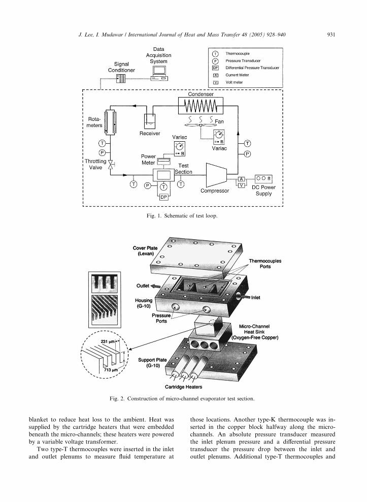
Table 2
Two-phase frictional pressure drop correlations based on separated flow model and corresponding MAE for R134a
Author(s) [Ref.] Remarks Frictional pressure drop correlation MAE (%)
Lockhart and Martinelli [1] Fluids: water, benzene, kerosene,
oil, etc. dh = 1.49–25.83mmDP f ¼
2G2Ltpdhxe;out
Z xe;out
xe;in
ffð1� xeÞvf/2f dxe
14.90
/2f ¼ 1þ C
X þ 1X 2 ;X 2 ¼ ½ðdP=dzÞf=ðdP=dzÞg�
C = 5 (laminar liquid–laminar vapor), C = 10
(turbulent liquid–laminar vapor), C = 12 (laminar
liquid–turbulent vapor), C = 20 (turbulent liquid–
turbulent vapor)
Friedel [2] dh = 4mm DP f ¼2f foG
2Ltpvfdhxe;out
Z xe;out
xe;in
/2fo dxe 24.00
/2fo ¼ A1 þ
3:24A2A3
Fr0:045tp We0:035tp
A1 ¼ ð1� xÞ2 þ x2qffgoqgffo
!;A2 ¼ x0:78ð1� xÞ0:224;
A3 ¼qf
qg
!0:91lg
lf
� �0:19
1�lg
lf
� �0:7
Frtp ¼ G2
gdh�q2;Wetp ¼ G2dh
�qr; �q ¼ 1
xevg þ ð1� xeÞvf
Mishima and Hibiki [5] Fluid: air–water mixture,
dh = 1–4mm
DP f ¼2G2Ltpdhxe;out
Z xe;out
xe;in
ffð1� xeÞvf/2f dxe 34.37
/2f ¼ 1þ C
Xþ 1
X 2; X 2 ¼ ½ðdP=dzÞf=ðdP=dzÞg�
C = 21[1�exp(�0.319 Æ dh)]; dh (mm)
Lee and Lee [8] Fluid: air–water mixture
dh = 0.78,6.67mm
DP f ¼2G2Ltpdhxe;out
Z xe;out
xe;in
ffð1� xeÞvf/2f dxe 16.04
/2f ¼ 1þ C
Xþ 1
X 2; X 2 ¼ ½ðdP=dzÞf=ðdP=dzÞg�
C ¼ c1kc2wc3Rec4fo; k ¼ l2
f
qfrdh;w ¼ lf jf
r, c1, c2, c3, c4
from Table 4 in Ref. [8]
Zhang and Webb [9] Fluids: R134a, R22, R404a,
dh = 2.13mm
DP f ¼2f foG
2Ltpvfdhxe;out
Z xe;out
xe;in
/2fo dxe 50.07
/2fo ¼ ð1� xeÞ2 þ 2:87x2
PP c
�1� �
þ 1:68x0:8e ð1� xeÞ0:25PP c
� ��1:64
J. Lee, I. Mudawar / International Journal of Heat and Mass Transfer 48 (2005) 928–940 935
The accelerational two-phase pressure drop was
expressed in terms of the evaporator�s inlet and outlet
conditions [1].
DP a ¼ G2vgx2e;outaout
þ vfð1� xe;outÞ2
ð1� aoutÞ
" #(
�vgx2e;inain
þ vfð1� xe;inÞ2
ð1� ainÞ
" #); ð10Þ
where the void fraction was determined from Zivi�s [18]popular relation
a ¼ 1þ 1� xexe
� �vfvg
� �2=3" #�1
: ð11Þ
Fig. 4 compares pressure drop predictions of the dif-
ferent separated flow correlations with the experimental
data. Interestingly, the predictions of the first two
macro-channel correlations are not as poor as first
thought. The small-channel correlations show apprecia-
ble deviation from the data.
Page 9
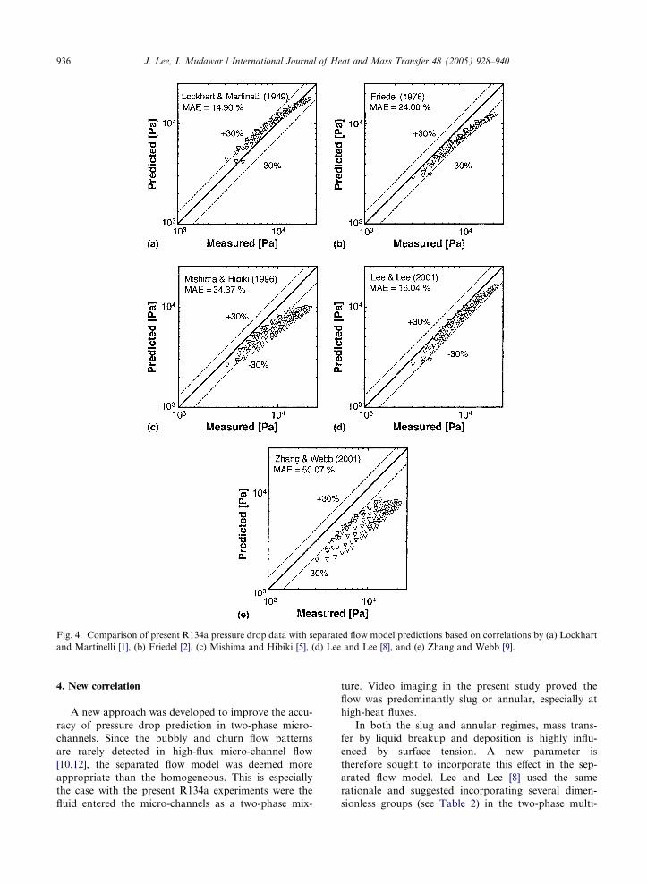
Fig. 4. Comparison of present R134a pressure drop data with separated flow model predictions based on correlations by (a) Lockhart
and Martinelli [1], (b) Friedel [2], (c) Mishima and Hibiki [5], (d) Lee and Lee [8], and (e) Zhang and Webb [9].
936 J. Lee, I. Mudawar / International Journal of Heat and Mass Transfer 48 (2005) 928–940
4. New correlation
A new approach was developed to improve the accu-
racy of pressure drop prediction in two-phase micro-
channels. Since the bubbly and churn flow patterns
are rarely detected in high-flux micro-channel flow
[10,12], the separated flow model was deemed more
appropriate than the homogeneous. This is especially
the case with the present R134a experiments were the
fluid entered the micro-channels as a two-phase mix-
ture. Video imaging in the present study proved the
flow was predominantly slug or annular, especially at
high-heat fluxes.
In both the slug and annular regimes, mass trans-
fer by liquid breakup and deposition is highly influ-
enced by surface tension. A new parameter is
therefore sought to incorporate this effect in the sep-
arated flow model. Lee and Lee [8] used the same
rationale and suggested incorporating several dimen-
sionless groups (see Table 2) in the two-phase multi-
Page 10
J. Lee, I. Mudawar / International Journal of Heat and Mass Transfer 48 (2005) 928–940 937
plier relation. As shown in Fig. 4(d), their approach
showed more favorable predictions of the present
R134a data than the other two small-channel
correlations.
A more mechanistic approach is adopted in the
present study. It is assumed the added complexity of
two-phase flow in a micro-channel is the net result of
interactions between liquid inertia, liquid viscous force,
and surface tension. Two key measures of these interac-
tions are the Reynolds and Weber numbers based on
liquid properties.
Refo ¼Gdh
lf
ð12aÞ
and
Wefo ¼vfG
2dh
r: ð12bÞ
Fig. 5. Comparison of new correlation predictions with (a)
present R134a data and (b) Qu and Mudawar�s [12] micro-
channel water data.
The two-phase pressure drop multiplier
/2f ¼ 1þ C
Xþ 1
X 2ð13Þ
is modified with a new dimensionless parameter defined
as
C ¼ c1Rec2foWe
c3fo : ð14Þ
To enhance the predictive capability of the new
correlation, both the present R134a data and prior
micro-channel water data of Qu and Mudawar [12] were
examined. Large differences between the thermophysical
properties of the two coolants were deemed highly effec-
tive at broadening the application range of the new cor-
relation. Another key difference between the two data
sets is both the liquid and vapor flows are laminar
for the water data, while low viscosity rendered the
vapor flow turbulent for R134a. Typical micro-channel
Fig. 6. Variation of measured R134a total pressure drop with
(a) exit quality for different heat fluxes, and (b) heat flux for
different mass velocities.
Page 11
938 J. Lee, I. Mudawar / International Journal of Heat and Mass Transfer 48 (2005) 928–940
operating conditions rarely produce turbulent liquid
flow. Therefore, two separate correlations were derived
for C based on the flow states of the liquid and vapor,
Cvv ¼ 2:16Re0:047fo We0:60fo ðlaminar liquid–laminar vaporÞð15aÞ
Cvt ¼ 1:45Re0:25fo We0:23fo ðlaminar liquid–turbulent vaporÞð15bÞ
Notice the stronger effect of surface tension where both
liquid and vapor are laminar.
Fig. 5(a) shows excellent agreement of the pressure
drop predictions based on the new correlation with the
R134a data, both in terms of MAE and general trend.
The largest deviation is concentrated in the low mass
flux and low heat flux region where both the heat loss
(which influences the accuracy of the heat flux used in
the pressure drop model) and the flow rate measurement
uncertainty are greatest.
Fig. 5(b) shows the present correlation is also very
effective at predicting the micro-channel water data of
Qu and Mudawar [12].
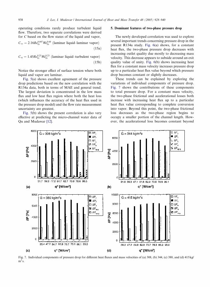
Fig. 7. Individual components of pressure drop for different heat fluxe
m2s.
5. Dominant features of two-phase pressure drop
The newly developed correlation was used to explore
several important trends concerning pressure drop in the
present R134a study. Fig. 6(a) shows, for a constant
heat flux, the two-phase pressure drop decreases with
increasing outlet quality due mostly to decreasing mass
velocity. This decrease appears to subside around an exit
quality value of unity. Fig. 6(b) shows increasing heat
flux for a constant mass velocity increases pressure drop
up to a particular heat flux value beyond which pressure
drop becomes constant or slightly decreases.
These trends can be explained by exploring the
variations of individual components of pressure drop.
Fig. 7 shows the contributions of these components
to total pressure drop. For a constant mass velocity,
the two-phase frictional and accelerational losses both
increase with increasing heat flux up to a particular
heat flux value corresponding to complete conversion
into vapor. Beyond this point, the two-phase frictional
loss decreases as the two-phase region begins to
occupy a smaller portion of the channel length. How-
ever, the accelerational loss becomes constant beyond
s and mass velocities of (a) 308, (b) 344, (c) 380, and (d) 415kg/
Page 12
J. Lee, I. Mudawar / International Journal of Heat and Mass Transfer 48 (2005) 928–940 939
the same point as the flow is converted completely into
vapor. Since the downstream portion of the channel is
now occupied mostly by vapor, the decreased two-
phase frictional loss is compensated for by a
measurable increase in the single-phase vapor pressure
loss. This explains why the total pressure drop be-
comes constant or decreases slightly with increasing
heat flux beyond the point of full conversion into
vapor.
6. Flow instabilities
Intrinsic to any refrigeration cycle, the throttling
valve located upstream of the evaporator offers impor-
tant benefits to the operation of a micro-channel evapo-
rator. Qu and Mudawar [12] proved the interaction of
the two-phase mixture with the upstream compressible
volume in a flow loop can trigger �severe pressure oscil-
lation� which is also a precursor for premature critical
heat flux (CHF). The throttling valve in the present sys-
tem imparted greater stiffness to the system, precluding
both this severe form of instability and the premature
CHF.
Despite its effectiveness at suppressing the severe
pressure oscillation, the micro-channel evaporator is
still susceptible to a second �parallel channel instability�
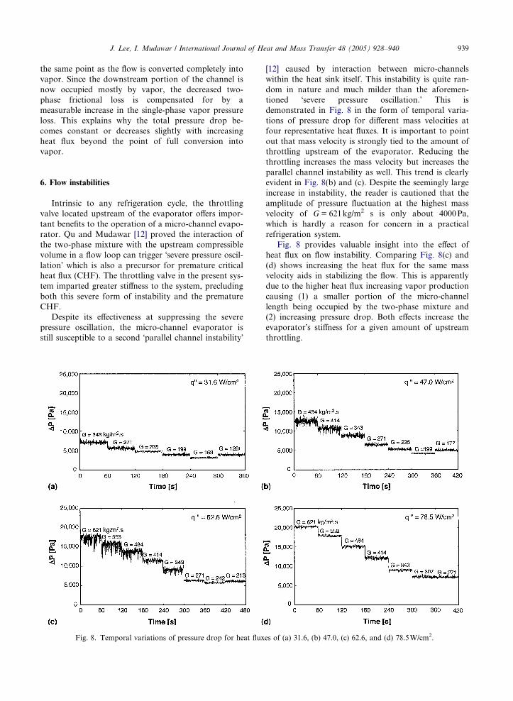
Fig. 8. Temporal variations of pressure drop for heat flux
[12] caused by interaction between micro-channels
within the heat sink itself. This instability is quite ran-
dom in nature and much milder than the aforemen-
tioned �severe pressure oscillation.� This is
demonstrated in Fig. 8 in the form of temporal varia-
tions of pressure drop for different mass velocities at
four representative heat fluxes. It is important to point
out that mass velocity is strongly tied to the amount of
throttling upstream of the evaporator. Reducing the
throttling increases the mass velocity but increases the
parallel channel instability as well. This trend is clearly
evident in Fig. 8(b) and (c). Despite the seemingly large
increase in instability, the reader is cautioned that the
amplitude of pressure fluctuation at the highest mass
velocity of G = 621kg/m2 s is only about 4000Pa,
which is hardly a reason for concern in a practical
refrigeration system.
Fig. 8 provides valuable insight into the effect of
heat flux on flow instability. Comparing Fig. 8(c) and
(d) shows increasing the heat flux for the same mass
velocity aids in stabilizing the flow. This is apparently
due to the higher heat flux increasing vapor production
causing (1) a smaller portion of the micro-channel
length being occupied by the two-phase mixture and
(2) increasing pressure drop. Both effects increase the
evaporator�s stiffness for a given amount of upstream
throttling.
es of (a) 31.6, (b) 47.0, (c) 62.6, and (d) 78.5W/cm2.
Page 13
940 J. Lee, I. Mudawar / International Journal of Heat and Mass Transfer 48 (2005) 928–940
7. Conclusions
The pressure drop characteristics were investigated
experimentally for a heat sinkwith parallel rectangularmi-
cro-channels that served as an evaporator in an R134a
refrigeration cycle. Both homogeneous equilibrium and
separated flow models were assessed for accuracy in pre-
dicting the new data, and a new correlation was developed
to improve the overall predictive capability of the latter.
Key findings from the study are as follows:
(1) Using several popular two-phase viscosity models,
the homogenous equilibrium model generally
underpredicted the present R134a data.
(2) Popular macro-channel separated flow model corre-
lations generally yielded better predictions of pres-
sure drop than some recent small-channel
correlations.
(3) Since two-phase flow in high-flux micro-channel
heat sinks is predominantly slug or annular, a new
correlation was developed that was based on the
separated flow model. The new correlation incorpo-
rates the effects of liquid inertia, viscous force and
surface tension on the two-phase pressure drop
multiplier. Excellent agreement is achieved between
pressure drop predictions based on the new correla-
tion and both present R134a data and prior micro-
channel water data.
(4) The total pressure drop generally increases with
increasing mass velocity and/or heat flux. However,
there is appreciable diminution in this increase
where complete conversion to vapor takes place
inside the micro-channels.
(5) The throttling valve in a refrigeration cycle offers
important benefits to the operation of a micro-
channel evaporator. By stiffening the system against
interactions between the two-phase flow in the
evaporator and the upstream compressible volume,
the throttling valve serves to suppress any large
pressure oscillations, allowing only mild parallel
channel instability to take place.
Acknowledgment
The authors are grateful for the support of the Office
of Naval Research (ONR) for this research.
References
[1] R.W. Lockhart, R.C. Martinelli, Proposed correlation of
data for isothermal two-phase, two-component flow in
pipes, Chem. Eng. Prog. 45 (1949) 39–48.
[2] J.G. Collier, J.R. Thome, Convective Boiling and Con-
densation, third ed., Oxford University Press, Oxford,
1994.
[3] D. Chisholm, Pressure gradients due to friction during the
flow of evaporation two-phase mixtures in smooth tubes
and channels, Int. J. Heat Mass Transfer 16 (1973) 347–
358.
[4] M.B. Bowers, I. Mudawar, Two-phase electronic cooling
using mini-channel and micro-channel heat sinks. Part 2:
flow rate and pressure drop constraints, ASME J. Electron.
Packag. 116 (1994) 298–305.
[5] K. Mishima, T. Hibiki, Some characteristics of air–water
two-phase flow in small diameter vertical tubes, Int. J.
Multiphase Flow 22 (1996) 703–712.
[6] K.A. Triplett, S.M. Ghiaasiaan, S.I. Abdel-Khalik, A.
LeMouel, B.N. McCord, Gas–liquid two-phase flow in
microchannels. Part II: void fraction and pressure drop,
Int. J. Multiphase Flow 25 (1999) 395–410.
[7] T.N. Tran, M.-C. Chyu, M.W. Wambsganss, D.M.
France, Two-phase pressure drop of refrigerants during
flow boiling in small channels: an experimental investiga-
tion and correlation development, Int. J. Multiphase Flow
26 (2000) 1739–1754.
[8] H.J. Lee, S.Y. Lee, Pressure drop correlations for two-
phase flow within horizontal rectangular channels with
small heights, Int. J. Multiphase Flow 27 (2001) 783–
796.
[9] M. Zhang, R.L. Webb, Correlation of two-phase friction
for refrigerants in small-diameter tubes, Exp. Therm. Fluid
Sci. 25 (2001) 131–139.
[10] A. Kawahara, P.M.-Y. Chung, M. Kawaji, Investigation
of two-phase flow pattern void, fraction and pressure drop
in a microchannel, Int. J. Multiphase Flow 28 (2002) 1411–
1435.
[11] W. Qu, I. Mudawar, Experimental and numerical study of
pressure drop and heat transfer in a single-phase micro-
channel heat sink, Int. J. Heat Mass Transfer 45 (2002)
2549–2565.
[12] W. Qu, I. Mudawar, Measurement and prediction of
pressure drop in two-phase micro-channel heat sinks, Int.
J. Heat Mass Transfer 46 (2003) 2737–2753.
[13] R.K. Shah, A.L. London, Laminar Flow Forced Convec-
tion in Ducts: A Source Book of Compact Heat Exchanger
Analytical Data, Academic Press, New York, 1978 (Suppl.
1).
[14] F.P. Incropera, D.P. Dewitt, Fundamentals of Heat and
Mass Transfer, fifth ed., Wiley, New York, 2002.
[15] Y.-Y. Yan, T.-F. Lin, Evaporation heat transfer
and pressure drop of refrigerant R-134a in a
small pipe, Int. J. Heat Mass Transfer 41 (1998) 4183–
4194.
[16] D.R.H. Beattie, P.B. Whalley, A simple two-phase flow
frictional pressure drop calculation method, Int. J. Multi-
phase Flow 8 (1982) 83–87.
[17] S. Lin, C.C.K. Kwok, R.Y. Li, Z.H. Chen, Z.Y. Chen,
Local frictional pressure drop during vaporization for R-
12 through capillary tubes, Int. J. Multiphase Flow 17
(1991) 95–102.
[18] S.M. Zivi, Estimation of steady-state stem void-fraction by
means of the principle of minimum entropy production,
ASME J. Heat Transfer 86 (1964) 247–252.


![Investigation of Heat Sink Efficiency for Electronic ...2013/01/26 · of heat sink, (mm) Number of fins Natural convection, Power dissipation [W], 60 ºC rise heat sink to ambient](https://static.documents.pub/doc/80x56/5f0eacc47e708231d44061ee/investigation-of-heat-sink-efficiency-for-electronic-20130126-of-heat-sink.jpg)