Table of Contents 1 TWR‐AUDIO‐SGTLOverview...............................................................................................................4
Figure 1. Freescale Tower System overview ............................................................................................... 4 Figure 2. Callouts on top side of the TWR‐AUDIO‐SGTL ............................................................................. 5 Figure 3. Assembled Tower System with TWR‐AUDIO‐SGTL module (in black) located in adjacent slot to processor module (in red) ........................................................................................................................... 6 Figure 4. Location of TWR‐AUDIO‐SGTL jumpers ....................................................................................... 9
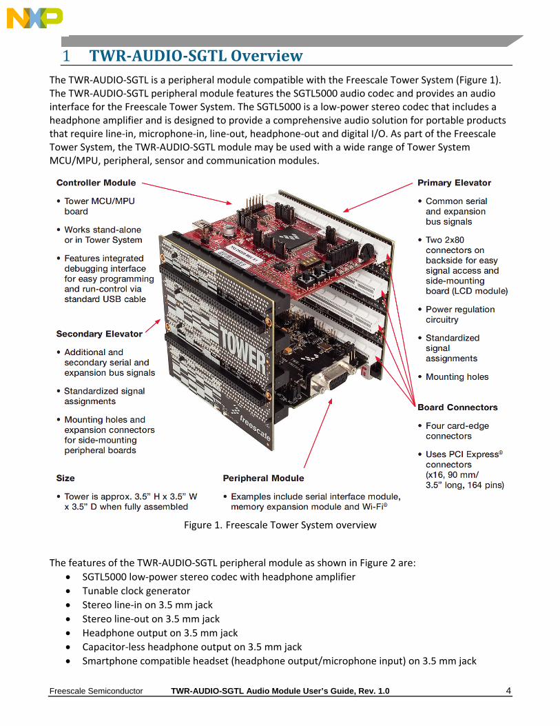
1 TWR‐AUDIO‐SGTLOverviewThe TWR‐AUDIO‐SGTL is a peripheral module compatible with the Freescale Tower System (Figure 1). The TWR‐AUDIO‐SGTL peripheral module features the SGTL5000 audio codec and provides an audio interface for the Freescale Tower System. The SGTL5000 is a low‐power stereo codec that includes a headphone amplifier and is designed to provide a comprehensive audio solution for portable products that require line‐in, microphone‐in, line‐out, headphone‐out and digital I/O. As part of the Freescale Tower System, the TWR‐AUDIO‐SGTL module may be used with a wide range of Tower System MCU/MPU, peripheral, sensor and communication modules.
Figure 1. Freescale Tower System overview
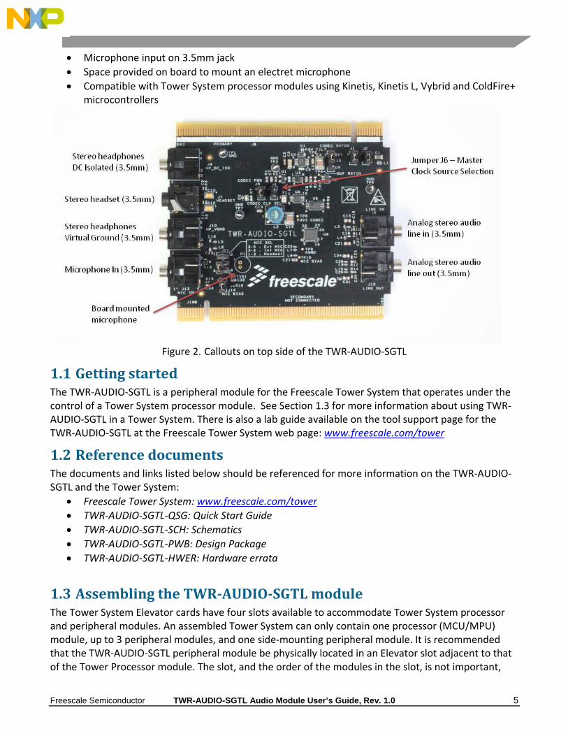
The features of the TWR‐AUDIO‐SGTL peripheral module as shown in Figure 2 are:
SGTL5000 low‐power stereo codec with headphone amplifier
Tunable clock generator
Stereo line‐in on 3.5 mm jack
Stereo line‐out on 3.5 mm jack
Headphone output on 3.5 mm jack
Capacitor‐less headphone output on 3.5 mm jack
Smartphone compatible headset (headphone output/microphone input) on 3.5 mm jack
Space provided on board to mount an electret microphone
Compatible with Tower System processor modules using Kinetis, Kinetis L, Vybrid and ColdFire+ microcontrollers
Figure 2. Callouts on top side of the TWR‐AUDIO‐SGTL
1.1 GettingstartedThe TWR‐AUDIO‐SGTL is a peripheral module for the Freescale Tower System that operates under the control of a Tower System processor module. See Section 1.3 for more information about using TWR‐AUDIO‐SGTL in a Tower System. There is also a lab guide available on the tool support page for the TWR‐AUDIO‐SGTL at the Freescale Tower System web page: www.freescale.com/tower
1.2 ReferencedocumentsThe documents and links listed below should be referenced for more information on the TWR‐AUDIO‐SGTL and the Tower System:
Freescale Tower System: www.freescale.com/tower
TWR‐AUDIO‐SGTL‐QSG: Quick Start Guide
TWR‐AUDIO‐SGTL‐SCH: Schematics
TWR‐AUDIO‐SGTL‐PWB: Design Package
TWR‐AUDIO‐SGTL‐HWER: Hardware errata
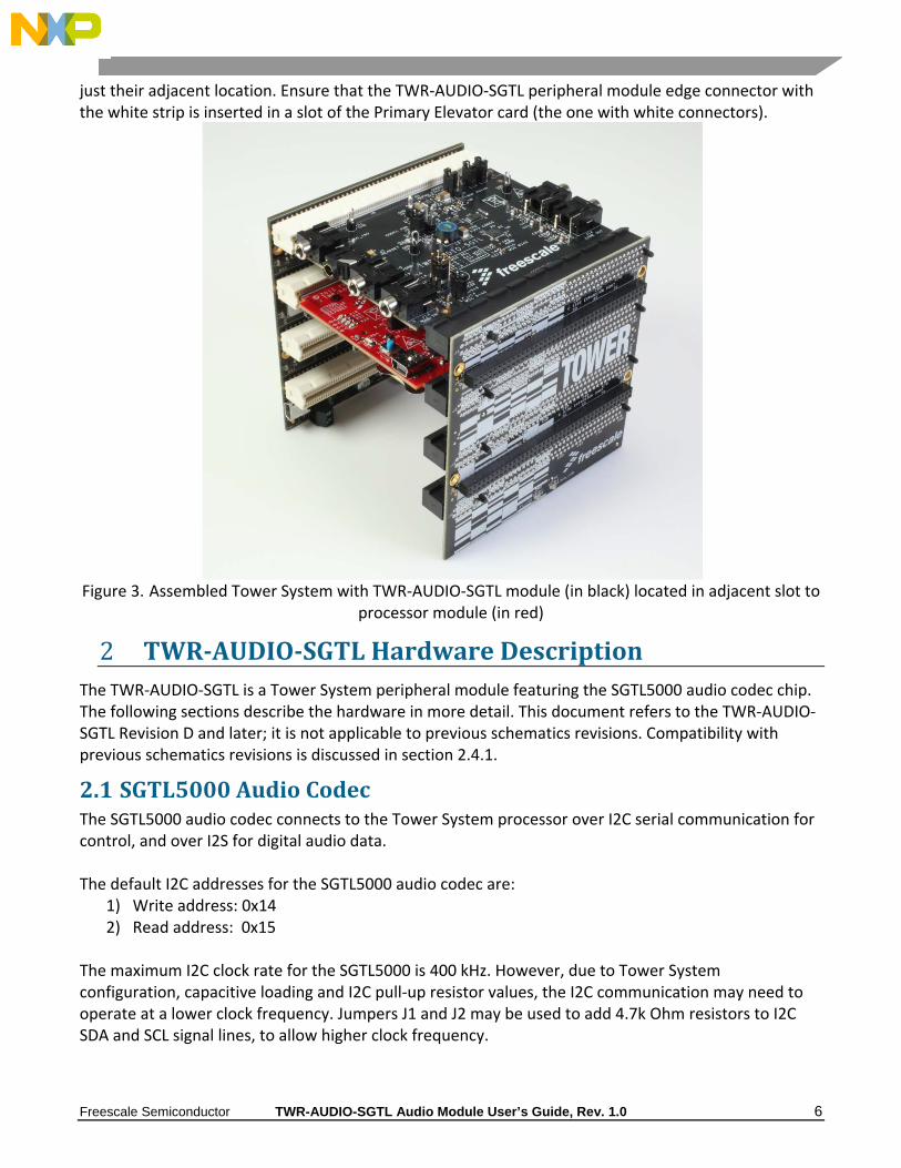
1.3 AssemblingtheTWR‐AUDIO‐SGTLmoduleThe Tower System Elevator cards have four slots available to accommodate Tower System processor and peripheral modules. An assembled Tower System can only contain one processor (MCU/MPU) module, up to 3 peripheral modules, and one side‐mounting peripheral module. It is recommended that the TWR‐AUDIO‐SGTL peripheral module be physically located in an Elevator slot adjacent to that of the Tower Processor module. The slot, and the order of the modules in the slot, is not important,
just their adjacent location. Ensure that the TWR‐AUDIO‐SGTL peripheral module edge connector with the white strip is inserted in a slot of the Primary Elevator card (the one with white connectors).
Figure 3. Assembled Tower System with TWR‐AUDIO‐SGTL module (in black) located in adjacent slot to
processor module (in red)
2 TWR‐AUDIO‐SGTLHardwareDescriptionThe TWR‐AUDIO‐SGTL is a Tower System peripheral module featuring the SGTL5000 audio codec chip. The following sections describe the hardware in more detail. This document refers to the TWR‐AUDIO‐SGTL Revision D and later; it is not applicable to previous schematics revisions. Compatibility with previous schematics revisions is discussed in section 2.4.1.
2.1 SGTL5000AudioCodecThe SGTL5000 audio codec connects to the Tower System processor over I2C serial communication for control, and over I2S for digital audio data. The default I2C addresses for the SGTL5000 audio codec are:
1) Write address: 0x14 2) Read address: 0x15
The maximum I2C clock rate for the SGTL5000 is 400 kHz. However, due to Tower System configuration, capacitive loading and I2C pull‐up resistor values, the I2C communication may need to operate at a lower clock frequency. Jumpers J1 and J2 may be used to add 4.7k Ohm resistors to I2C SDA and SCL signal lines, to allow higher clock frequency.
Digital audio data is transported between the SGTL5000 and the processor over I2S data lines. The master/slave configuration is defined by software drivers. Note master clock requirements of the SGTL5000 for appropriate configuration.
2.2 Si5351AClockGeneratorThe Si5351A tunable clock generator connects to the Tower System processor over I2C serial communication for control. Its default output frequency is 24.576MHz. The output frequency can be changed by programming its internal registers over I2C communication. The I2C addresses for the Si5351A tunable clock generator are:
1. Write address: 0xDE 2. Read address: 0xDF
2.3 HarwareResetConsiderationsThe SGTL5000 chip has internal power‐on hardware reset, but no external hardware reset input. Optionally, in a development environment, the power to the TWR‐AUDIO‐SGTL can be forced to cycle through power off/on when the Tower System processor module asserts the hardware reset signal. Jumper J3 allows selection of the hardware reset functionality:
1) For J3 in position 1‐2: Tower System processor module hardware reset does not cycle the TWR‐AUDIO‐SGTL power.
2) For J3 in position 2‐3: Tower System processor module hardware reset will initiate a power off/power up cycle of the TWR‐AUDIO‐SGTL circuitry. The power off state will last approximately 20 msec.
2.4 MasterClockSourceSelectionThere is a choice of two master clock sources for the SGTL5000 in the TWR‐AUDIO‐SGTL module. The selection is done with jumper J6:
1) J6 off: Local Si5351A tunable clock generator (24.576MHz default frequency) 2) J6 on: Master clock from the Tower processor module I2S port
The TWR‐AUDIO‐SGTL Rev D module can replace previous module revisions after proper selection of the master clock source. To replace a Rev B module, ensure that jumper J6 is on (inserted in position 1‐2), to select the master clock from the Tower processor module. To replace a Rev B1 module, ensure that jumper J6 is off (not inserted in position 1‐2), to select the master clock from the on‐board clock generator.
2.5 I2SInterfaceThe I2S interface has a serial data input, a serial data output, a frame sync clock (also called left/right clock) and a serial bit clock. The two clock lines are used to clock both data lines. The I2S signals are connected to the Tower System processor module I2S port.
2.6 I/OconnectorsAll the input and output connectors on the TWR‐AUDIO‐SGTL are described in the following sections.
The analog audio line level stereo output is available at the stereo 3.5mm connector J12. These outputs support loads of 10k Ohm or more.
2.6.2 Analogaudiolinelevelstereoinput
The analog audio line level stereo input is available at the stereo 3.5mm connector J9.
2.6.3 Analogaudiostereoheadphoneoutputs
The analog audio stereo headphone outputs are available as follows: 1) At the 3.5mm connectors J4 and J7 – through DC blocking capacitors 2) At the 3.5mm connector J10 – using virtual headphone ground and no DC blocking capacitors
The SGTL5000 audio codec can drive a single headphone load, so only one of connectors J4, J7 or J10 may be used at a time. Note that the capacitor‐less headphone output at connector J10 must be used only with stereo headphones. This output should not be used to connect to amplifiers, or to headsets with microphones, otherwise the virtual headphone ground may be short‐circuited. Recommended headphone impedance is in the range of 16 to 32 Ohms.
2.6.4 Analogaudiomonomicrophoneinputs
There are three options for microphone input to the SGTL5000: 1) Board mounted microphone P1 – the TWR‐AUDIO‐ SGTL module ships without the P1
microphone on the board. If desired, P1 can be soldered at its location on the board. Recommended P1 microphone is the Panasonic part WM‐64PCT or equivalent. Microphone bias must be supplied by ensuring that jumper J14 is in position 1‐2. This input is selected when jumper J11 is in position 3‐4.
2) External microphone input 3.5mm connector J13 – a microphone from a PC headset can be plugged into the J13 connector. Microphone bias is supplied from a 3.3V source through a 10k Ohm resistor. This input is selected when jumper J11 is in position 3‐5.
3) Smartphone headset input 3.5mm connector J7 – a Smartphone headset with headphones and microphone can be plugged into the J7 connector. Microphone bias must be supplied by ensuring that jumper J14 is in position 1‐2. The iPhone® headset is compatible with the J7 connector. This input is selected when jumper J11 is in position 1‐3.
Note that not all Smartphone headsets are compatible with the signals at the J7 connector. Ensure that the headset 3.5mm plug has the correct signal connectivity as shown below:
1) Tip: Headphone Left Channel Output 2) Ring: Headphone Right Channel Output 3) Ring: Ground 4) Sleeve: Microphone Input
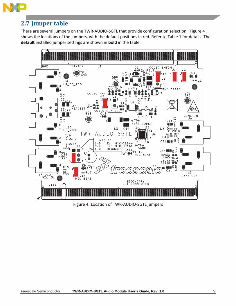
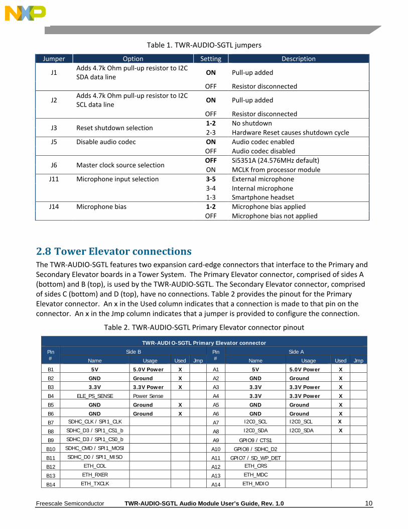
2.7 JumpertableThere are several jumpers on the TWR‐AUDIO‐SGTL that provide configuration selection. Figure 4 shows the locations of the jumpers, with the default positions in red. Refer to Table 1 for details. The default installed jumper settings are shown in bold in the table.
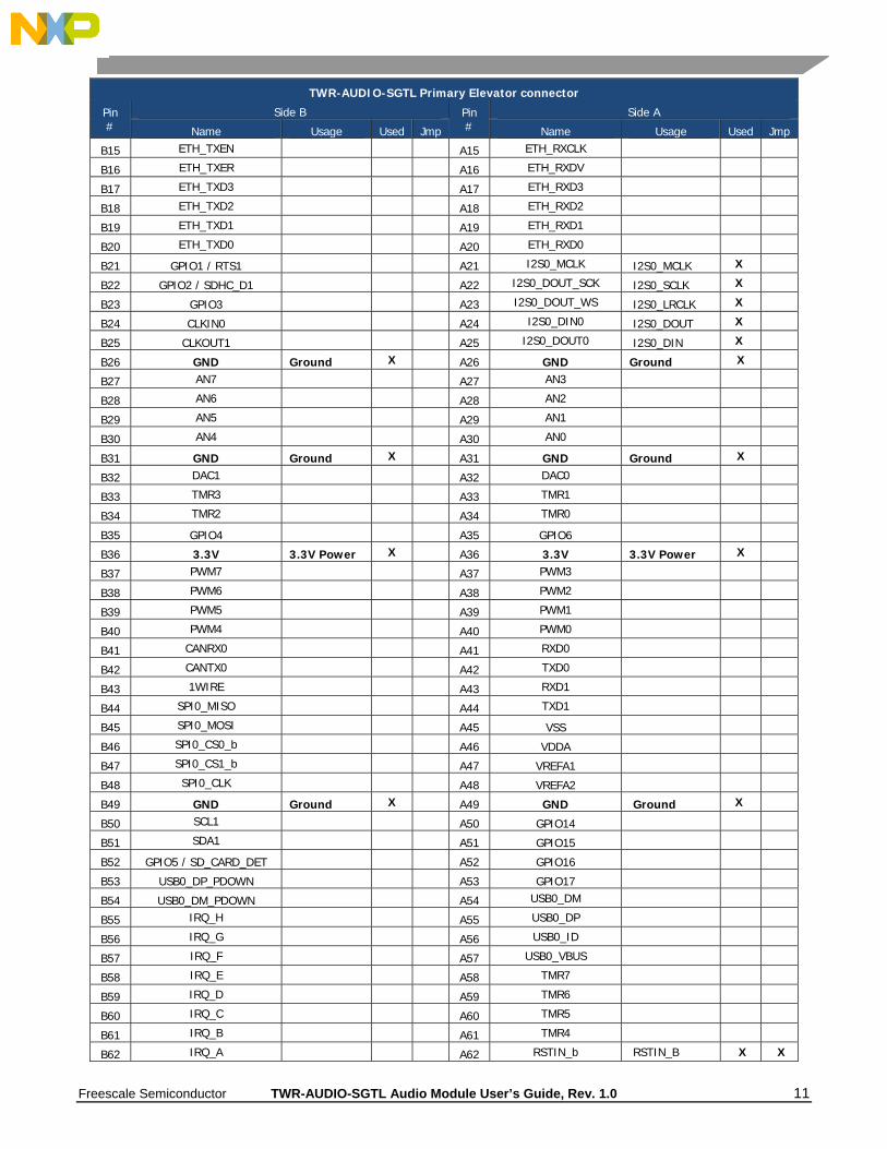
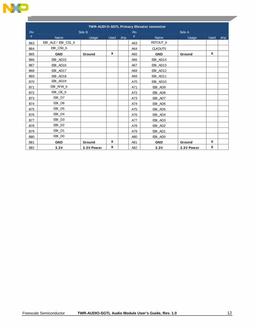
2.8 TowerElevatorconnectionsThe TWR‐AUDIO‐SGTL features two expansion card‐edge connectors that interface to the Primary and Secondary Elevator boards in a Tower System. The Primary Elevator connector, comprised of sides A (bottom) and B (top), is used by the TWR‐AUDIO‐SGTL. The Secondary Elevator connector, comprised of sides C (bottom) and D (top), have no connections. Table 2 provides the pinout for the Primary Elevator connector. An X in the Used column indicates that a connection is made to that pin on the connector. An X in the Jmp column indicates that a jumper is provided to configure the connection.
Table 2. TWR‐AUDIO‐SGTL Primary Elevator connector pinout
FCC CLASS A DEVICE: "This device complies with part 15 of the FCC Rules. Operation is subject to the following two conditions: (1) This device may not cause harmful interference, and (2) this device must accept any interference received, including interference that may cause undesired operation." CE EMC Directive: This device complies with European Union EMC Directive and the Low Voltage Safety Directive (LVD) [Product exhibits some anomalous behavior observed over the frequency range of 125 MHz‐350 MHz during Immunity testing]
How to Reach Us: Home Page: freescale.com Web Support: freescale.com/support
Information in this document is provided solely to enable system and software implementers to use Freescale products. There are no express or implied copyright licenses granted hereunder to design or fabricate any integrated circuits based on the information in this document. Freescale reserves the right to make changes without further notice to any products herein. Freescale makes no warranty, representation, or guarantee regarding the suitability of its products for any particular purpose, nor does Freescale assume any liability arising out of the application or use of any product or circuit, and specifically disclaims any and all liability, including without limitation consequential or incidental damages. “Typical” parameters that may be provided in Freescale data sheets and/or specifications can and do vary in different applications, and actual performance may vary over time. All operating parameters, including “typicals,” must be validated for each customer application by customer’s technical experts. Freescale does not convey any license under its patent rights nor the rights of others. Freescale sells products pursuant to standard terms and conditions of sale, which can be found at the following address: freescale.com/SalesTermsandConditions.
Freescale, the Freescale logo, Kinetis, and Coldfire+ are trademarks of Freescale Semiconductor, Inc., Reg. U.S. Pat. & Tm. Off. Vybrid and Tower are trademarks of Freescale Semiconductor, Inc. All other product or service names are the property of their respective owners.