trolex.com trolex.com trolex.com ISSUE K 06/15 trolex.com INSTALLATION & OPERATING DATA PETROCHEMICAL PROCESSING • MINING & TUNNELLING contents... page 1 PRINCIPAL OPERATING FEATURES 2 2 APPLICATION 3 3 DIMENSIONS 4 4 TECHNICAL DETAILS 4 5 INSTALLATION 6 6 CONNECTIONS 10 7 CONTROLS AND INDICATORS 12 8 THE MENU OF FUNCTIONS 13 9 PROGRAMMING AND CALIBRATION 14 1 0 MAINTENANCE 24 1 1 APPROVALS AND CERTIFICATION 26 TX6141/TX6143 PRESSURE SENSOR/TRANSMITTER 1/27
Transcript
t rolex.comtrolex.comtrolex.comISSUE K 06/15
t rolex.com
INSTALLATION &OPERATING DATA
PETROCHEMICALPROCESSING
•MINING &
TUNNELLING
contents... pa g e
1 PRINCIPAL OPERATING FEATURES 2
2 APPLICATION 3
3 DIMENSIONS 4
4 TECHNICAL DETAILS 4
5 INSTALLATION 6
6 CONNECTIONS 10
7 CONTROLS AND INDICATORS 12
8 THE MENU OF FUNCTIONS 13
9 PROGRAMMING AND CALIBRATION 14
1 0 MAINTENANCE 24
1 1 APPROVALS AND CERTIFICATION 26
TX6141/TX6143PRESSURE SENSOR/TRANSMITTER
1/27
t rolex.comtrolex.com
INSTALLATION & OPERATING DATA
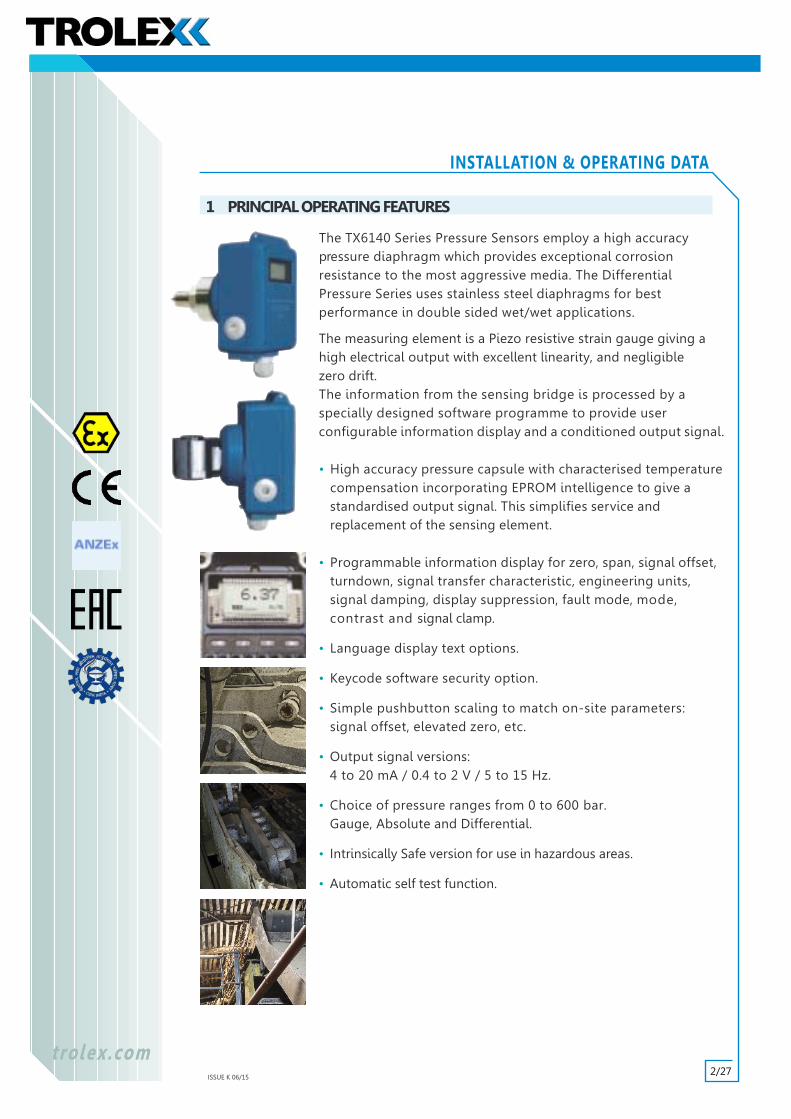
The TX6140 Series Pressure Sensors employ a high accuracypressure diaphragm which provides exceptional corrosionresistance to the most aggressive media. The DifferentialPressure Series uses stainless steel diaphragms for bestperformance in double sided wet/wet applications.
The measuring element is a Piezo resistive strain gauge giving ahigh electrical output with excellent linearity, and negligiblezero drift.The information from the sensing bridge is processed by aspecially designed software programme to provide userconfigurable information display and a conditioned output signal.
• High accuracy pressure capsule with characterised temperaturecompensation incorporating EPROM intelligence to give astandardised output signal. This simplifies service andreplacement of the sensing element.
• Programmable information display for zero, span, signal offset,turndown, signal transfer characteristic, engineering units,signal damping, display suppression, fault mode, mode,contrast and signal clamp.
• Language display text options.
• Keycode software security option.
• Simple pushbutton scaling to match on-site parameters:signal offset, elevated zero, etc.
• Output signal versions:4 to 20 mA / 0.4 to 2 V / 5 to 15 Hz.
• Choice of pressure ranges from 0 to 600 bar.Gauge, Absolute and Differential.
• Intrinsically Safe version for use in hazardous areas.
• Automatic self test function.
1 PRINCIPAL OPERATING FEATURES
2/27ISSUE K 06/15
t rolex.comtrolex.com
INSTALLATION & OPERATING DATA
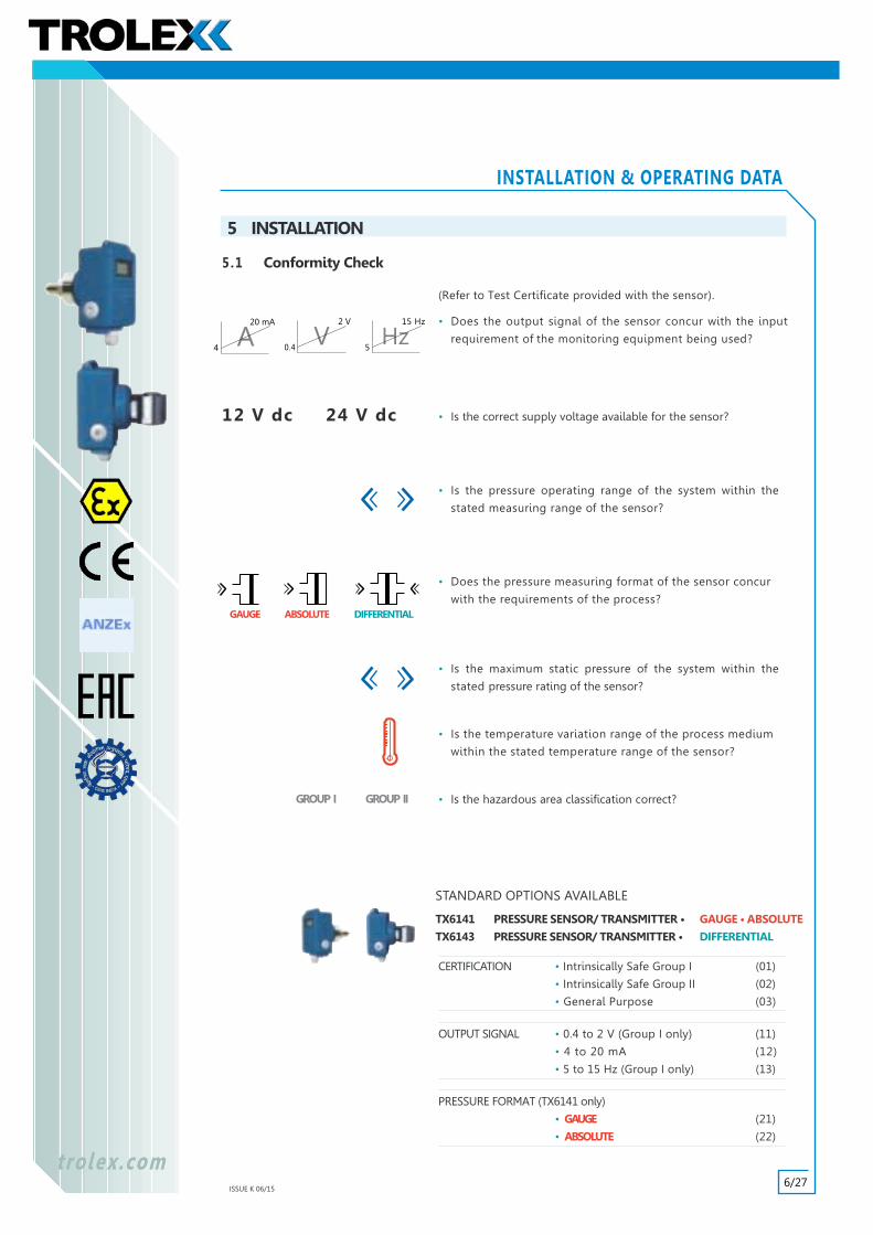
High accuracy analogue pressure measurement in process systemsand plant monitoring applications, with data communications forinterfacing with display/control instruments and distributedcontrol systems.
• GAUGE pressure measurement in pipes, vessels, containers, receivers and process equipment.
• ABSOLUTE pressure measurement for atmospheric pressure monitoring, environmental monitoring and process systems.
• DIFFERENTIAL pressure measurement, hydrostatic levelsensing in pressurised vessels, process pressure comparison,DP flow measurement in pipes and ventilation ducts,blocked filter detection, DP measurement across pumps andhydraulic machinery, transformer cooling circuits, etc.
• A choice of output signals for direct interfacing with moststandard industrial monitoring systems.
2 APPLICATION
TRIP AMPLIFIERfor use with analogueoutput pressure sensors.
CONFIGURABLE SENSOR CONTROLLERfor monitoring up to 8 pressure sensors.
COMMANDER DISTRIBUTED I/OSYSTEMfor large scale general plant monitoring systemsand the mining and tunnelling industries.
• A range of primary instrumentation and monitoring modulesis available from Trolex to which the sensors can be directlyconnected to provide a flexible choice of display andcontrol functions.
3/27ISSUE K 06/15
t rolex.comtrolex.com
INSTALLATION & OPERATING DATA
3 DIMENSIONS
15
3
1/2"
BSP
T
27
17074
63110
76
ALL DIMENSIONS IN MM
1/4" BSP
24146
7463
1/4" BSP
50
2 Holes M8 x 12 deepfor M8 fixing screws
= 28 =
=
=
15
3
110
76
3.1TX6141
GAUGE
ABSOLUTE
3.2TX6143
DIFFERENTIAL
STAINLESS STEELDIAPHRAGM
4 TECHNICAL DETAILS
4.1 SpecificationOverall Accuracy: ±0.25%.
Long Term Drift: ±0.5% per annum.
Linearity: ±0.25%.
Temperature Stability: ±0.06% / °C. Ambient
Temp. Limits: Housing: –10 to +50°C.Sensor: –20 to +150°C.
Humidity: 0 to 95% non-condensing.
Vibration Limits: 0.25 min pk (10 Hz to 100 Hz)2 g pk (100 Hz to 600 Hz)40 g (Impact)
Protection Classification: Dust and waterproof to IP66.
All output signal options of the sensor are certified Intrinsically
Safe for use in Group II hazardous areas, zones 0, 1 and 2, when
used in conjunction with zener safety barriers or isolation safety
barriers. Only the sensor may be mounted in the hazardous
1 2 3 4 5
TX6140
6 7 8
TX9031
HAZ SAFE
2 WIRE
6.4 Group II Hazardous Areas
IMPORTANTEnsure that the sensor is the INTRINSICALLY SAFE
version; TX6141.02/TX6143.02
Suggested Zener safety barrier: MTL7087 +
Suggested Isolating safety barrier: MTL5042
If you require any help in the use of safety barriers please contact the
Trolex Technical Department.
All output signal options of the sensor are certified Intrinsically
Safe for the use in Group I hazardous areas (Mining) when used
with approved equipment eg. TX9130 Series Trip Amplifier or a
TX9042 Programmable Sensor Controller.
The complete system, both sensor and monitoring device can
be mounted in the hazardous area.
6.5 Group I Hazardous Areas (Mining)
IMPORTANTEnsure that the sensor is the INTRINSICALLY SAFE
Group I version; TX6141.01/TX6143.01
1 2 3 4 5
TX6140
6 7 8
TX9132
HAZ
SAFE
3/4 WIRE
4 WIRE
11/27ISSUE K 06/15
Power Supply
t rolex.comtrolex.com
INSTALLATION & OPERATING DATA
7 CONTROLS AND INDICATORS
• Hold the SCROLL Keys down for two seconds for rapid self keying.
• All data settings are retained under power failure.
The programming and setting routines for the sensor have been designed forutmost simplicity and the programming system is completely menu driven. There is nospecial software programme and a data input terminal and/or PC is not required.
There are just four keys for controlling the complete operation and the digital displayprovides instructions throughout the programming process. All entries areverified in the display.
2 . 5 3b a r
Signal Display(section 9.2)
Function Display(section 9.3)
Bargraph(section 9.2)
Units(section 9.7.4)
s / w V e r s i o n
v 1 . 1
Software version.
Key
Data Review
EXIT SCROLLUP
SCROLLDOWN
CONFIRM
O t o 1 O b a r
S e n s r
Key
Range of the pressuresensing module fitted
(Section 4.3)
12/27ISSUE K 06/15
t rolex.comtrolex.com
INSTALLATION & OPERATING DATA
8 THEMENU OFFUNCTIONS
ENTER
FUNCTION
9.6
Sectionreferencein data
Initialdefaultsetting
????
–1234
MASTER RESET9.9
KEY CODE9.6
SCALING9.7 TURNDOWN
CALIBRATION9.8 ZERO
TURNDOWN9.7.1 0
UNITS9.7.2 bar
LANGUAGE9.8.1 GB
DEC PLACE9.8.2 00.00
DAMPING9.8.3 1
KEYCODEMENU
9.3ENTERKEYCODE
9.6SIGNAL DISPLAY
9.1
SCALE FACTOR9.7.3 L
FAULT MODE9.7.4 UP
FIX OUTPUT9.8.4 0
CONTRAST9.8.5 25
KEYCODE
13/27ISSUE K 06/15
t rolex.comtrolex.com
INSTALLATION & OPERATING DATA
9.1 Switching On
When switched on, the processor will initialise all the default
values unless new values have previously been programmed.
9 PROGRAMMINGAND CALIBRATION
2 . 5 3b a r
9.2 Signal Display
After two seconds, the display will switch to the SIGNAL DISPLAY
mode, showing the measured signal value with the selected
engineering units (bar).
• The bargraph will also show an indication of the input
signal level.
• Signal over range.
b a r
b a r
9.3 Entering the MENU
All the operating functions of the sensor can be programmed
by entering into the MAIN MENU.
Key or to SCROLL up and down the MENU.
Key to CONFIRM.
M E N UK e y C o d eS c a l i n gC a l i b r a t i o nM a s t e r R e s e t
• Entry SAVED will appear briefly whenever a new value is
entered during programming.
• NOT SAVED will appear briefly if a value is not entered
during programming.
Previously programmed values will be shown in themain sectors of the display. Function changes can
be programmed as describedin the following
sections.
E N T R Y S A V E D
2 . 5 3
N O T S A V E D
9.4 Exit
Key to EXIT from any position in the MENU sequence.
Each operation of the key will revert the display one step back
in the MENU table until the SIGNAL DISPLAY is reached.
14/27ISSUE K 06/15
9.6.2 Set Keycode
Access to ALL menu items can be prevented.
The keycode is a selectable option and the code can be
changed at any time.
The keycode can also be set to be ACTIVE or NOT ACTIVE.
Key to TRAVERSE the cursor.
Key to INCREMENT the digit with the cursor under.
Key to CONFIRM.
t ro lex .comtro lex .com
INSTALLATION & OPERATING DATA
9 PROGRAMMING AND CALIBRATION continued
+ 1 2 3 4E n t e r K C o d e
– NOT ACTIVE (Unrestricted Access)
+ ACTIVE (NO Access)
O O O OE n t e r K C o d e
G ON O G O
9.6 Keycode
A four digit security keycode can be entered to prevent
unauthorised access to ALL setup items in the menu.
9.6.1 Enter Keycode
This entry screen will only show if an active keycode has been set. If
the entered keycode is accepted, the display moves on to the
MENU section. If the entered keycode is invalid, the display
returns to the normal measurement mode.
Key to TRAVERSE the cursor.
Key to INCREMENT the digit with the cursor under.
Key to CONFIRM.
GO or NO GO will appear briefly to confirm keycode status.
9.5 Self Test
The processor will constantly carry-out a self-test routine of the
main circuit elements; EPROM, memory, comms and display
read/write function.
Any malfunction registered will be denoted by a FAIL message in
the display. The output signal will also be forced to the UPSCALE or
DOWNSCALE condition, whichever one
is selected as the FAULT MODE. Refer to Section 9.7.4
F A I L! ! ! ! ! ! ! ! ! ! ! !
This request will not appear if the KEYCODEis not active.
Refer to Section 9.6.2
15/27ISSUE K 06/15
9.7 Scaling
The scaling of the output signal and the corresponding value
of pressure presented on the display of the sensor is
accurately calibrated, in bar, during manufacture.
There are three standard output signal formats available, each
representing the maximum operating pressure range (bar) of
the sensor.
The various parameters of the signal scale and display values
can be modified to suit the individual characteristics
and imperatives of a particular installation or process.
• Turndown or pressure operating range.
• Change the units of display from bar to another.
• Apply linear or non-linear scale multipliers.
• Upscale or downscale fault-mode selections.
Key or to SELECT the function.
Key to CONFIRM.
t rolex.comtrolex.com
INSTALLATION & OPERATING DATA
9 PROGRAMMING AND CALIBRATION continued
AppliedPressure
Display
OutputSignal
20 mA
4 mA
4 to 20 mA output 0.4 to 2 V output 5 to 15 Hz output
S C A L ET u r n d o w n
U n i t sS c a l e F a c t o r
F a u l t M o d e
Making any of the modifications to the SCALING
parameters naturally assumes that the fundamental
pressure calibration of the sensor is accurate.
Although this will be so on a new sensor, it is good
safety practice to re-affirm the pressure calibration at
periodic intervals.
If calibration is necessary – do it
BEFORE making any modifications
to the scaling parameters.
Operating PressureRange: bar
20 mA(Upper)
4 mA(Lower)
Operating PressureRange: bar
2 V(Upper)
0.4 mA(Lower)
Operating PressureRange: bar
15 Hz(Upper)
5 Hz(Lower)
Refer to Section 9.8
16/27ISSUE K 06/15
9.7.1 Turndown
The sensor may be installed in an application that requires a lower
operating pressure range than the standard calibratedrange (e.g. 5 bar utilisation on a 10 bar full scale sensor).
The complete response range of the output signal can be utilised
by 'Turning Down' the sensor response to the required maximum
pressure range of the system being monitored.
Key to TRAVERSE the cursor.
Key to INCREMENT the digit with the cursor under.
Key to CONFIRM.
INSTALLATION & OPERATING DATA
5 bar 10 bar(Lower)
Ou
tpu
t
0
1 O . O OS e t T u r n d o w n
Adjustable Range:25% to 100% of full scale
O 5 . O OS e t T u r n d o w n
9 PROGRAMMING AND CALIBRATION continued
The overall response accuracy of the
sensor is defined at the MAXIMUM
calibrated pressure range.
Be aware that any TURNDOWN applied will slightly
reduce the overall response accuracy in proportion to
the amount of turndown introduced.
Refer to Section 4.1
9.7.2 Units
PRESSURE UNITS
The sensor is calibrated in bar (gauge pressure) during
manufacture. There is a choice of alternative units of pressure
measurement:
All display values within the SCALING and
CALIBRATION functions will automatically be presented
in the PRESSURE units selected.
If the sensor is being used to measure hydrostatic
pressure (level) using the metre (m) or feet (ft) units,
remember to include a correction
factor for the specific gravity of
the liquid, if necessary. Refer to Section 9.7.3
Units of measurement must be restricted to the
choice listed in the PRESSURE UNITS menu.
Special consideration is needed for units within the
VOLUMETRIC and FLOW menus.
Key or to SELECT the UNITS.
Key to CONFIRM.m m H 2 OinH2Of t H 2 Om m H gi n H g
m ba rb a rp s ik P aMPaAtm
mf t
m3
f t 3
lg a l U Kg a l U S
m / sf t / s
l / m i n
S e l e c t U n i t s
FlowUnits(DifferentialPressure)
VolumetricUnits
PressureUnits
17/27ISSUE K 06/15
20 mA 20 mA (Upper)
t rolex.comtrolex.com
INSTALLATION & OPERATING DATA
VOLUMETRIC UNITS
When the sensor is being used to measure the hydrostatic
pressure level of a liquid, the processor can be setup to calculate
the contained VOLUME.
It will also be necessary to enter an appropriate multiplication
factor relating to the response characteristics
of the orifice plate or venturi system used.
9 PROGRAMMING AND CALIBRATION continued
Refer to Section 9.7.3
Leve
lSensor
csa
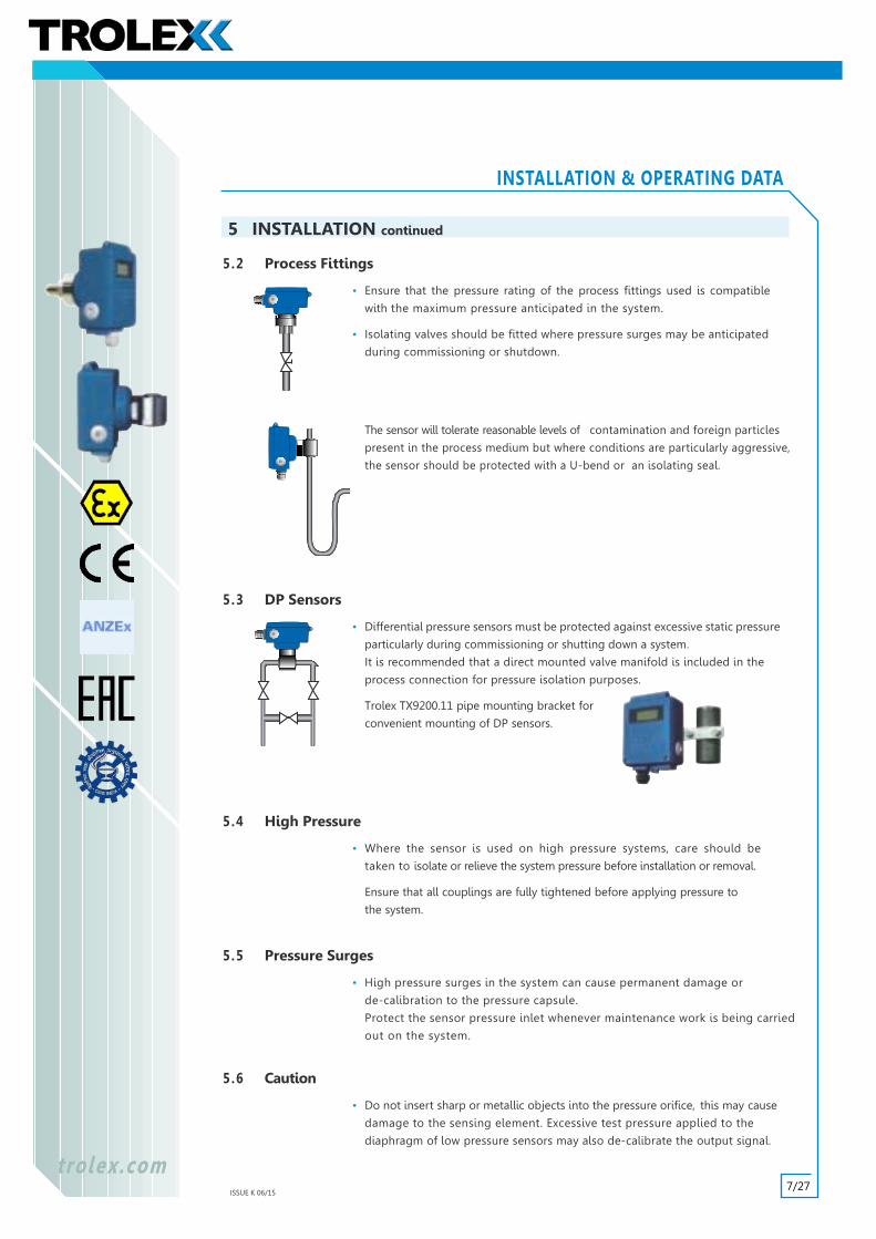
FLOW UNITS (Differential Pressure)
One of the three FLOW measurement units may be selected
where a TX6143 series Differential Pressure Sensor is installed
across an orifice plate or venturi to monitor flow velocity.
Any one of these selections will automatically produce a
square-root transfer function in the sensor processor for use with
DP measuring points, so enabling the sensor to provide a
linearised output signal.
It will be necessary to enter an appropriate multiplication factor
relating to the response characteristics of the
orifice plate or venturi system being used.Refer to Section 9.7.3
18/27ISSUE K 06/15
t rolex.comtrolex.com
INSTALLATION & OPERATING DATA
9.7.3 Scale Factor
Multiplication factors can be entered for SPECIFIC GRAVITY
correction or for use with the VOLUMETRIC
and FLOW functions.
Specific Gravity Correction
Where the sensor is applied to hydrostatic level measurement,
the choice of units available is m or ft,
calibrated with respect to water.
If the specific gravity of the liquid being monitored is different to
that of water a correction factor may be entered:
Factor = SG of liquid (ie: 0.9).
Key to TRAVERSE the cursor.
Key to INCREMENT the digit with the cursor under.
Key to CONFIRM.
VOLUMETRIC UNITS
If one of the five VOLUMETRIC measurement
units is selected, it will be necessary to enter
a multiplication factor relating to the
cross-sectional area of the vessel.
Factor = Cross-sectional area x SG.
9 PROGRAMMING AND CALIBRATION continued
Refer to Section 9.7.2
Refer to Section 9.7.2
O O . 9 OS e t S c l F c t r
Refer to Section 9.7.2
Leve
l
Sensor
csa
• The cross-sectional area Factor MUST be entered in the
corresponding dimensional units.
Unit Cross-sectional Area
m3/s square metres (m2)
ft3 square feet (ft2)
l square metres (m2)
gal square feet (ft2)
1 . O OS e t S c l F c t r
Key to TRAVERSE the cursor.
Key to INCREMENT the digit with the cursor under.
Key to CONFIRM.
19/27ISSUE K 06/15
t rolex.comtrolex.com
INSTALLATION & OPERATING DATA
FLOW UNITS (Differential Pressure)
One of the three FLOW measurement units flow may be selectedwhere a TX6143 series Differential Pressure Sensor is installed acrossan orifice plate or venturi to monitor flow velocity. Any one of theseselections will automatically produce a square-root law transferfunction in the sensor processor for use with DPmeasuring points,so enabling the sensor to provide a linearised output signal.
It will be necessary to enter an appropriate multiplication factorrelating to the response characteristics of the orifice plate or venturisystem used.
This relationship can be mathematically calculated if sufficient datais available relating to the structure of the process flow system andthe dynamic characteristics of the flow medium.
Alternatively the scaling factor can be easily established by taking asample measurement of the actual flow velocity, together with ameasurement of the associated differential pressure and applyingthe formula:
Factor = Flow • Flow measured in the units of flow
selected in the menu.
• DP measured in bar.
Key to TRAVERSE the cursor.
Key to INCREMENT the digit with the cursor under.
Key to CONFIRM.
9 PROGRAMMING AND CALIBRATION continued
DP
2 . 5 OS e t S c l F c t r
0.1
20 40 60Flow Rate (L/min)
80 1000
0.2
0.3
0.4
0.5
Pres
sure
Acr
oss
Ven
turi
(bar
)
Response characteristic of aventuri system in a Ø25 pipe.
4 mA DOWNSCALE
UPSCALE
20 mA
U PF a u l t M o d e
D O W N
9.7.4 Fault Mode
The output signal of the sensor can be selected to go UPSCALE
or DOWNSCALE when a sensor malfunction or connection
failure occurs.
If a sensor is monitoring low pressure failure on a pressurised
system the DOWNSCALE failure mode will force the output signal
down into the system alarm region.
Similarly, the UPSCALE failure mode will initiate an alarm in a
system that is employed to monitor excess pressure level.
Key or to SELECT the MODE.
Key to CONFIRM.
20/27ISSUE K 06/15
t rolex.comtrolex.com
INSTALLATION & OPERATING DATA
9.8 Calibration
The scaling of the output signal and the corresponding value of
pressure presented on the display of the sensor is accurately
calibrated, in bar, during manufacture.
There are three standard output signal formats available, each
representing the maximum operating pressure range (bar) of
the sensor.
The fundamental calibration of the sensor with respect to an
applied pressure should be checked at periodic intervals using a
calibrated pressure source.
Setup functions are available when fundamental pressure
re-calibration has become necessary.
• The language used in the display.
• Damping adjustment of the sensor response.
• Fix the output signal during calibration or servicing.
• Adjust the contrast of the display.
Key or to SELECT the function.
Key to CONFIRM.
9 PROGRAMMING AND CALIBRATION continued
4 to 20 mA output 0.4 to 2 V output
Operating PressureRange: bar
20 mA(Upper)
4 mA(Lower)
Operating PressureRange: bar
2 V(Upper)
0.4 V(Lower)
Operating PressureRange: bar
15 Hz(Upper)
5 Hz(Lower)
AppliedPressure
Display
OutputSignalFix
Damping20 mA
4 mA
PressureCalibration
C A L I BL a n g u a g eS e t Z e r o
S e t S p a nD e c . P l a c e
D a m p i n gO u t p u t Z e r o
O u t p u t S p a nF i x O u t p u t
C o n t r a s t
9.8.1 Language
The display text can be shown in five different languages.
English (GB) French (F) Spanish (E) German (D) Czech (CZ)
Key or to SELECT.
Key to CONFIRM.
G BS e t L a n g u a g e
FED
C Z
5 to 15 Hz output
21/27ISSUE K 06/15
t rolex.comtrolex.com
INSTALLATION & OPERATING DATA
9.8.2 Decimal Place
When the sensor is measuring a rapidly fluctuating signal, the
fluttering minor digits in the display can be distracting.
The position of the decimal point can be moved to any
position in the figure to minimise this effect.
Key or to TRAVERSE the decimal point.
Key to CONFIRM.
9 PROGRAMMING AND CALIBRATION continued
O O . O OS e t D . P
Range: 0.000 to 00000
O O 1 . OS e t D a m p i n g
Range: 0 to 999.9s
9.8.3 Damping
The immediacy of response of the sensor can be DAMPED to filter
unwanted spurious changes in the process pressure.
Key to TRAVERSE the cursor.
Key to INCREMENT the digit with the cursor under.
Key to CONFIRM.
• The value entered approximates to the time taken in
seconds for the signal to reach 63% of the final value
(ie. one time constant).
9.8.4 Fix Output
It may be necessary, to temporarily shut down the process to
carry out maintenance or servicing which will probably mean
removing the system pressure.
To prevent an alarm condition being transmitted by the sensor,
the output signal can be temporarily FIXED at any desired
PERCENTAGE value of the output signal range.
The FIXED LEVEL selected is a calibrated value so this feature can
also be used to test the integrity of the signal loop and any
remote monitoring equipment, by simulating an output signal
of defined value.
Remote display systems can be calibrated and any alarm set
point levels can be checked for function and accuracy.
Key to TRAVERSE the cursor.
Key to INCREMENT the value of the digit with the cursor
under.
Key to CONFIRM.
O O . O OS e t O / P S i g
Range: 0 to 99.99%
The signal will be RELEASED when the MENU position
is vacated.
Fix
%
20 mA
4
22/27ISSUE K 06/15
t rolex.comtrolex.com
INSTALLATION & OPERATING DATA
9 PROGRAMMING AND CALIBRATION continued
C o n t r a s t
5 O
Range: 100 = Minimum Contrast0 = Maximum Contrast
9.8.5 Contrast
The contrast of the LCD can be varied to compensate for
the effect of ambient temperature and light conditions.
Key or to SET the contrast.
Key to CONFIRM.
R E S E TW a i t . . .
9.9 Master Reset
All data will be re-initialised.
Key to RESET.
The display will return to the SIGNAL DISPLAY mode.
Refer to Section 8
23/27ISSUE K 06/15
There are no degradable components, but it is good safety practice to
carry out regular preventative maintenance to confirm correct operation.
10.1 Output Signal
Check at regular intervals, that the value of the output
signal agrees with the value of the display reading.
Re-calibrate if necessary.
10.2 Pressure Capsule
Under normal circumstances, the calibration of the actual
pressure capsule will not change by any significant degree.
Check the accuracy at least once per year by comparing
the display reading with an accurate standard.
10.3 Seals and Couplings
Periodically check the tightness of the process couplings and the
condition of pressure seals.
10.4 Main Circuit Module
The main circuit module inside the sensor housing can
be removed from the housing for maintenance purposes.
Disconnect the ribbon cable from the capsule PCB.
10.5 Annual Safety Check
The main transmitter itself will not normally require maintenance
or calibration but it is advisable to return it to the Trolex Product
Support Department for an annual safety check.
10.6 Damaged Sensors
A Sensor that has been dropped or damaged in any way
should be taken out of service immediately for inspection,
repair and re-calibration.
10.7 Record Keeping
Institute a regular calibration and maintenance procedure
and keep a record.
Incorrect use of the Sensor or inadequate maintenance may
not necessarily be self evident in the Sensor and consequently
it must
t rolex.comtrolex.com
INSTALLATION & OPERATING DATA
10 MAINTENANCE
Refer to Section 9.8
Alternatively the sensor can be returned to our ProductSupport Department for checking and calibration.
24/27ISSUE K 06/15
t rolex.comtrolex.com
INSTALLATION & OPERATING DATA
10.8 Maintenance and Calibration Log
ORDER REF: TX DATE SUPPLIED
SERIAL No. USER
PRESSURE RANGE LOCATION
10 MAINTENANCE continued
DATE SCHEDULED FAILURE RE-CALIBRATE CHANGE GAS RETURN TO COMMENTSSENSING MANUFACTURER
MODULE
25/27ISSUE K 06/15
t rolex.comtrolex.com
INSTALLATION & OPERATING DATA
11 APPROVALS AND CERTIFICATION
11.1 Europe (ATEX)
TX6141 and TX6143 Pressure Sensor/Transmitter
Ex Certificate number: SIRA 00ATEX2001X
Ex Certification codes: I M1 EEx ia I (Ta = -20°C to +60°C)
II 1G EEx ia IIC T4 (Ta = -20°C to +60°C)
Special Conditions for Safe Use
The TX614x Pressure Sensors/Transmitters shall not be installed where the external conditionscould cause a build-up of electrostatic charges on their non-conducting surfaces. Additionally, theequipment shall only be cleaned with a damp cloth.
The safety description of the TX614x Pressure Sensor/Transmitter has changed as a result ofvariation 2. Consequently, the products that incorporate these modifications may not be suitableas a direct replacement for those that are manufactured to the previous design. Therefore, theuser/installer shall ensure that the TX614x Pressure Sensor/Transmitter is compatible with theequipment to which it is intended to be connected.
General Conditions for Safe Use
Prior to installation, it is essential that user refers to the above certificate to ensure that thetermination and cable parameters are fully complied with and are compatible with the application.Copies of certificates are available from Trolex.
ATEX Directive (94/9/EC)
11.2 Australia/NewZealand (ANZEx)
TX6141 and TX6143 Pressure Sensor/Transmitter
Ex Certificate number: ANZEx 12.3013X
Ex Certification codes: Ex ia I (Ta = -20°C to +60°C)
Ex ia IIC T4 (Ta = -20°C to +60°C) IP54
Special Conditions for Safe Use
The TX614x Temperature Sensors / Transmitters shall not be installed where the externalconditions could cause a build-up of electrostatic charges on their non-conducting surfaces (clearpolycarbonate window). Additionally, the equipment shall only be cleaned with a damp cloth.
General Conditions for Safe Use
Prior to installation, it is essential that user refers to the above certificate to ensure that thetermination and cable parameters are fully complied with and are compatible with the application.Copies of certificates are available from Trolex.
11.3 Russia (Customs Union)
Ex certificate number: TC RU C-GB.ГБ05.B.00326
Ex Certification codes: PO Ex ia I Ma X
0Ex ia IIC Ga T4 X
Conditions of Use
Prior to installation, it is essential that user refers to the above certificate for any specific conditionsof use. The user must ensure that the termination and cable parameters are fully complied withand are compatible with the application. Copies of certificates are available from Trolex.


![[PSS 2A-1C15 B] Model IMV25 for P, DP, and T …indecx.co.za. Series PRESSURE TRANSMITTER FAMILY The I/A Series Electronic Pressure Transmitters ... TRANSMITTER SENSOR TEMPERATURE](https://static.documents.pub/doc/80x56/5adacc6c7f8b9ae1768daa81/pss-2a-1c15-b-model-imv25-for-p-dp-and-t-series-pressure-transmitter-family.jpg)


