Tyan S1846 Tsunami ATX Motherboard Users Manual Revision 1.60-01 Copyright ' Tyan Computer Corporation, 1999. All rights reserved. No part of this manual may be reproduced or translated without prior written consent from Tyan Computer Corp. All registered and unregistered trademarks and company names contained in this manual are propery of their respective companies including, but not limited to the following. AMIBIOS is a trademark of American Megatrend Incorporated. Windows is a trademark of Microsoft Corporation. IBM, PC, AT, PS/2 are trademarks of IBM Corporation. INTEL, Pentium II, Pentium III, Celeron are trademarks of Intel Corporation. S1846 Tsunami and Tsunami-ATX are trademarks of TYAN Computer Corporation. Information contained in this publication has been carefully checked for accuracy and reliability. In no event will Tyan Computer be held liable for any direct or indirect, incidental or consequential damage, loss of use, loss of data, or other malady resulting from errors or inaccuracies of information contained in this manual. The information contained in this document is subject to change without notice. PRINTED IN TAIWAN .
All registered and unregistered trademarks and company names contained in thismanual are propery of their respective companies including, but not limited to thefollowing.AMIBIOS is a trademark of American Megatrend Incorporated.Windows is a trademark of Microsoft Corporation.IBM, PC, AT, PS/2 are trademarks of IBM Corporation.INTEL, Pentium II, Pentium III, Celeron are trademarks of Intel Corporation.S1846 Tsunami and Tsunami-ATX are trademarks of TYAN Computer Corporation.
Information contained in this publication has been carefully checked for accuracy andreliability. In no event will Tyan Computer be held liable for any direct or indirect,incidental or consequential damage, loss of use, loss of data, or other malady resultingfrom errors or inaccuracies of information contained in this manual. The informationcontained in this document is subject to change without notice.
2. Board Installation..................................................................................... 10Unpacking....................................................................................... 10Precautions...................................................................................... 10Installation Steps............................................................................ 11What is a Jumper?.......................................................................... 12Map of Motherboard Jumpers..................................................... 13Picture of Motherboard Features................................................ 14Setting Jumpers.............................................................................. 15Mounting the Motherboard in the Chassis............................... 18Installing Memory.......................................................................... 19Installing the CPU and Cooling Fan............................................ 23Connecting IDE and Floppy Drives............................................ 30Connecting the Power Supply...................................................... 32Installing Add-on Cards................................................................ 33Connecting PS/2, USB, Serial & Parallel Devices...................... 34Frequently Asked Questions....................................................... 35
3. BIOS Configuration................................................................................. 36Main Setup...................................................................................... 37Advanced CMOS Setup.............................................................. 42Chipset Setup.................................................................................. 47Power Management Setup............................................................ 53Plug and Play/PCI Setup............................................................... 57Peripheral Setup............................................................................. 62Supervisor and User Security...................................................... 66Language Utility............................................................................. 67Flash Writer Utility......................................................................... 67
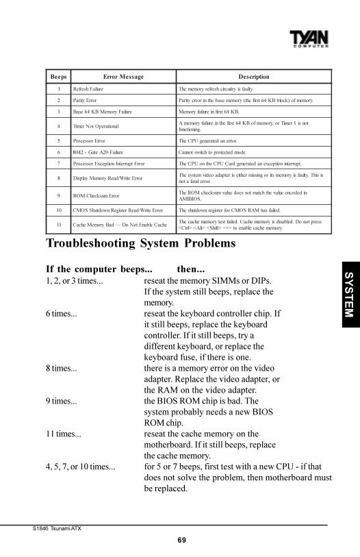
4. System Resources.................................................................................... 68Beep Codes..................................................................................... 68Troubleshooting System Problems............................................. 69
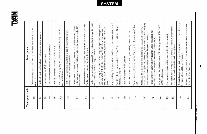
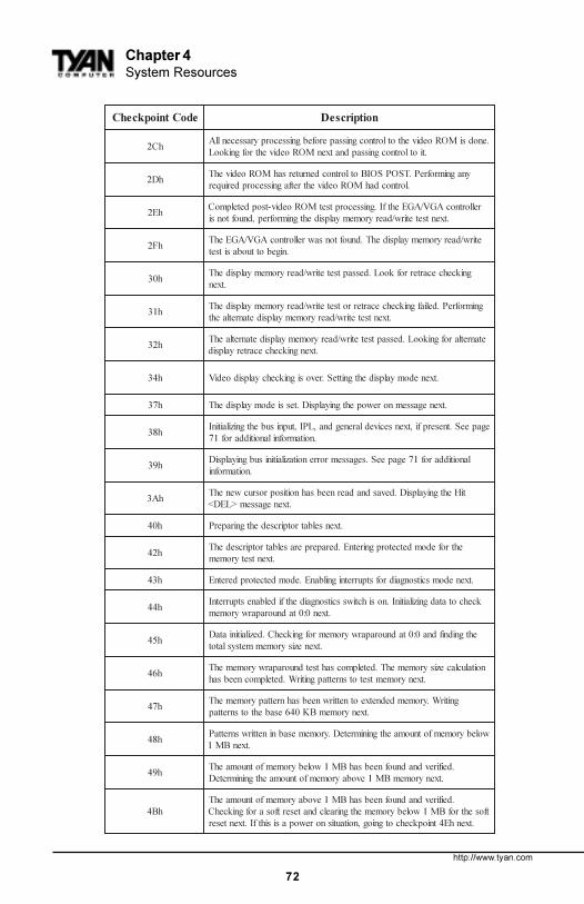
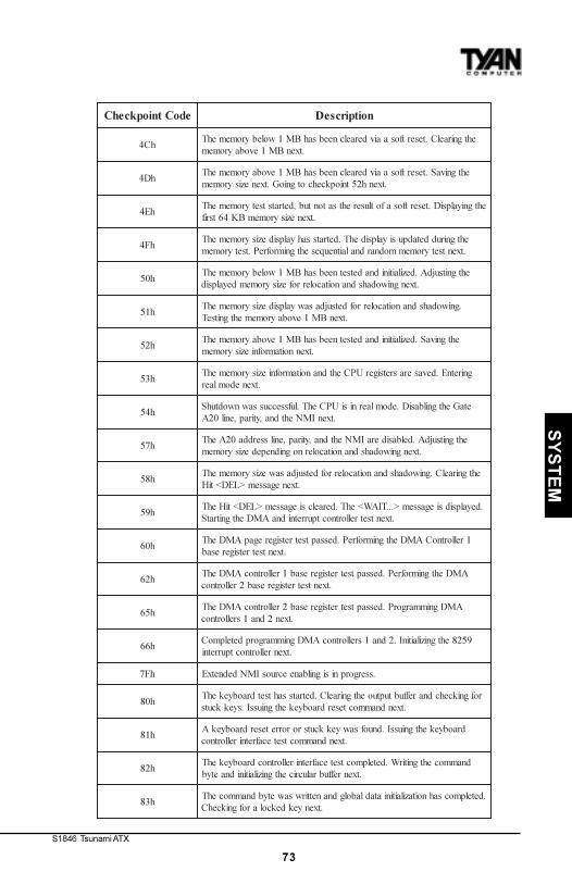
POST Checkpoint Codes.............................................................. 70Displayed Error Messages.......................................................... 77
Appendix 1 - CPU Retention Module Options.......................................... 80
The S1846 (S1846S and S1846SLA) Tsunami ATX is a quality, high perfor-mance motherboard designed for Intel Pentium II & P-III microprocessors. Thismotherboard utilizes the Intel 440BX AGPset and can support CPU speeds of233MHz through 500MHz, and host bus speeds of 66MHz to 100MHz.
The S1846 motherboard, with built-in AGP slot, provides high performancecapabilities that are ideal for a wide range of demanding applications such asCAD, CAM, CAE, desktop publishing, 3D animation, and video production.
This integrated system board achieves high reliability with numerous featuresand yet is small enough to be supported in an ATX form factor. Some of thefeatures included are onboard dual channel PCI PIO, BUS Master IDE andUltraDMA/33, onboard floppy controller, and onboard high speed I/O.
Flexibility and expandability have been designed into the Tsunami ATX. WithI/O and drive controller support built onboard, the one AGP slot, five PCI andtwo ISA slots (one shared, seven usable) are free for numerous add-onexpansion cards.
Remember to take a look at TYAN Computer�s web site located athttp://www.tyan.com. There you can find information on all of TYAN�s
chap
ter 1
Introduction
S1846 Tsunami ATX
5
INT
RO
products along with FAQs, distributors list, drivers, and BIOS setting explana-tions.
Icons
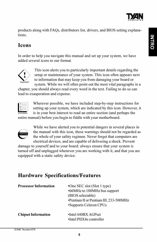
In order to help you navigate this manual and set up your system, we haveadded several icons to our format.
This icon alerts you to particularly important details regarding thesetup or maintenance of your system. This icon often appears nextto information that may keep you from damaging your board orsystem. While we will often point out the most vital paragraphs in a
chapter, you should always read every word in the text. Failing to do so canlead to exasperation and expense.
Wherever possible, we have included step-by-step instructions forsetting up your system, which are indicated by this icon. However, itis in your best interest to read an entire section (and perhaps the
entire manual) before you begin to fiddle with your motherboard.
While we have alerted you to potential dangers in several places inthe manual with this icon, these warnings should not be regarded asthe whole of your safety regimen. Never forget that computers areelectrical devices, and are capable of delivering a shock. Prevent
damage to yourself and to your board: always ensure that your system isturned off and unplugged whenever you are working with it, and that you areequipped with a static safety device.
Hardware Specifications/Features
Processor Information �One SEC slot (Slot 1 type)�66MHz to 100MHz bus support(BIOS selectable)�Pentium II or Pentium III, 233-500MHz�Supports Celeron CPUs
Chipset Information �Intel 440BX AGPset�Intel PIIX4e controller
!important!
procedure
1.2.3.
warning
http://www.tyan.com
6
Chapter 1Introduction
�National 309 Super I/O chipset
Voltage and Power �ATX power supply connectorInformation �+12V power source for DC fan onboard
�3.3V DRAM support�Utilizes GTL+ bus to reduce powerconsumption and EMI
Main Memory �Up to 768MB onboard�Three 168-pin DIMM sockets�Supports 100MHz SDRAM with SPD
System Management �Optional National LM79 and LM75 ASICswith onboard alarm for monitoring temperature,supply voltages, and fan speed�Intel LANDesk Client Manager software(optional with LM79 installed)�Chassis intrusion detection capable
Expansion Slots �One 32-bit AGP slot�Five 32-bit PCI Bus Master slots�Two 16-bit ISA slots�One shared ISA-PCI / seven usable slots
BIOS Information �AMI Plug and Play flash BIOS�Deep Green, Energy Star, ACPI, Year 2000, andPC98 compliant�Soft power-down, multiple bootoptions�Win98/NT5 ready, DMI 2.0 compliant�PCI 2.1, APM 1.1 compliant
Disk Drive & System I/O �Two PCI bus mastering EIDE
S1846 Tsunami ATX
7
INT
RO
channels�Supports EIDE CD-ROMs�PIO Mode 3 & 4 (up to 17MB/sec DTR)�UltraDMA/33 bus mastering mode (up to33MB/sec DTR)�Support for two floppy drives (up to 2.88MB)�Two serial ports (16550 UARTs)�One ECP/EPP parallel port�One IR (InfraRed) I/O interface port�Two USB rev 1.2 (universal serial bus)connectors�One PS/2 mouse connector�One PS/2 keyboard connector
Ensoniq ES 1371 AudioPCI �AC97 Codec(S1846SLA only) �Uses a single, shared IRQ
�High performance PCI bus master�Spatial enhanced 3D sound (SWS)�Wavetable synthesis built in�Joystick, Audio in, Speaker, Microphoneconnectors
Warranty �3 year manufacturer�s warranty
Software Specifications
OS �Operates with MS-DOS, Windows 3.x,Windows for WorkGroup 3.x, Windows 95,Windows 98, Windows NT, OS/2, NovellNetware, Solaris, and SCO Unix
Technical Support
If a problem arises with your system, you should turn to your dealer for helpfirst. Your system has most likely been configured by them, and they shouldhave the best idea of what hardware and software your system contains.Hence, they should be of the most assistance. Further, if you purchased yoursystem from a dealer near to you, you can actually bring your system in tothem to have it serviced, instead of attempting to do so yourself (which canhave expensive consequences).
http://www.tyan.com
8
Chapter 1Introduction
Help resources:1. See FAQ and beep codes sections of this manual.2. See Tyan web site for FAQ, bulletins, driver updates, etc.
http://www.tyan.com3. Contact your dealer or distributor for help BEFORE calling Tyan.4. Email Tyan tech support: [email protected]. Call Tyan tech support: 510-440-8808
Returning Merchandise for Service
During the warranty period, contact your distributor or system vendor FIRSTfor any product problems. This warranty only covers normal customer use anddoes not cover damages incurred during shipping or failure due to thealteration, misuse, abuse, or improper maintenance of products.
For Resellers Only:A receipt or copy of your invoice marked with the date of purchase is requiredbefore any warranty service can be rendered. You can obtain service by callingthe manufacturer for a Return Merchandise Authorization (RMA) number. TheRMA number should be prominently displayed on the outside of the shippingcarton and the package should be mailed prepaid, or hand-carried to themanufacturer. TYAN will pay to have the board shipped back to you.
S1846 Tsunami ATX
9
INT
RO
This page left blank intentionally.
http://www.tyan.com
10
Chapter 2Board Installation
chap
ter 2
Board Installation
!important!
Unpacking
The motherboard package should contain the following:(1) S1846S(LA) mainboard(1) 40-pin IDE and 34-pin floppy cable pack(1) S1846 User�s Manual(1) CPU Retention module(1) Driver Disk (S1846S only)(1) System Management & Driver CD with Ensoniq AudioPCI manual and
installation instructions (1846SLA only)
Precautions
What�s the first thing I should do?The first thing you should do is read this user�s manual. It contains importantinformation which will make configuration and setup much easier.
Here are some precautions you should follow when installing yourmotherboard:
(1) Ground yourself properly before removing your motherboard from the antistatic bag. Unplug the power from your computer and then touch any metal part on the computer case. (Or wear a grounded wrist strap.)
S1846 Tsunami ATX
11
INS
TAL
L
(2) Hold the motherboard by its edges and do not touch the bottom of the board.(3) Avoid touching motherboard components, IC chips, connectors, and leads.(4) Avoid touching pins of memory modules and chips.(5) Place motherboard on a grounded antistatic surface or on the antistatic bag.
Having reviewed the precautions above, the next step is to take the mother-board out of the cardboard box and static bag, hold it by its edges, and place iton a grounded antistatic surface, component side up. Inspect the board fordamage.
DO NOT APPLY POWER TO THE BOARD IF IT HAS BEEN DAMAGED!
Press down on any of the socket ICs if it appears that they are not properlyseated (the board should still be on an antistatic mat). Do not touch the bottomof the board. Remember, don�t take any electronic device out of its protectivebag until you are ready to actually install it into the computer case. If you donot ground yourself, you risk zapping the motherboard or adapter card.Subsequent problems may not arise immediately because electrostatic dis-charge damage, unlike physical damage, causes the device to fail over time.
*Power Supply Requirement: ATX Power Supply should be 2.01 compliant.Standby current must be 750mA or higher (SB5V = 0.75A)
Installation Steps
You are now ready to install your motherboard. The mounting hole pattern ofthe Tsunami ATX matches the ATX system board specifications. Your chassisshould be able to accomodate an ATX motherboard and have an ATX powersupply.
1. Set Jumpers2. Mount Motherboard in Chassis3. Install Memory4. Install CPU & Cooling Fan5. Connect IDE and Floppy Drives6. Connect Power Supply7. Install Add-on Cards8. Connect PS/2, USB, Serial and Parallel Devices
warning
procedure
1.2.3.
http://www.tyan.com
12
Chapter 2Board Installation
2 pin jumpers
off on
3 (or more) pin jumpers
1-2 2-3 open
123
123
123
Figure 2-1 Figure 2-2
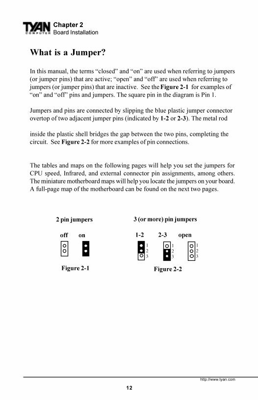
What is a Jumper?
In this manual, the terms �closed� and �on� are used when referring to jumpers(or jumper pins) that are active; �open� and �off� are used when referring tojumpers (or jumper pins) that are inactive. See the Figure 2-1 for examples of�on� and �off� pins and jumpers. The square pin in the diagram is Pin 1.
Jumpers and pins are connected by slipping the blue plastic jumper connectorovertop of two adjacent jumper pins (indicated by 1-2 or 2-3). The metal rod
inside the plastic shell bridges the gap between the two pins, completing thecircuit. See Figure 2-2 for more examples of pin connections.
The tables and maps on the following pages will help you set the jumpers forCPU speed, Infrared, and external connector pin assignments, among others.The miniature motherboard maps will help you locate the jumpers on your board.A full-page map of the motherboard can be found on the next two pages.
S1846 Tsunami ATX
13
INS
TAL
L
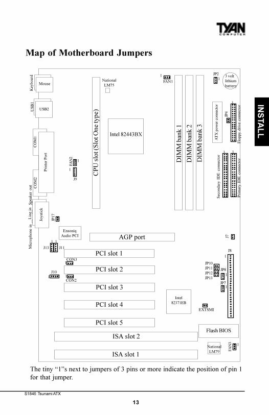
Map of Motherboard Jumpers
The tiny �1�s next to jumpers of 3 pins or more indicate the position of pin 1for that jumper.
JP10JP11JP12JP13
USB
1K
eybo
ard
USB2
Mouse
DIM
M b
ank
2
DIM
M b
ank
3
DIM
M b
ank
1
Prim
ary
IDE
con
nect
or
3 voltlithiumbattery
CO
M2
CO
M1
Prin
ter P
ort
PCI slot 2
PCI slot 3
AGP port
PCI slot 4
PCI slot 5
ISA slot 2
ISA slot 1
Flash BIOS
1J8
Intel 82443BX
PCI slot 1
CP
U s
lot (
Slot
One
type
)
Intel82371EB
FAN
3 1
Seco
ndar
y ID
E c
onne
ctor
Flop
py d
rive
con
nect
or
AT
X p
ower
con
nect
or
NationalLM79
NationalLM75
EXTSMI
1JP8
1
1JP2
FAN1
1
1
FAN
2
1
J9
EnsoniqAudio PCI
1
J11
1
J13
J101 1
1CON3
CON2
Joys
tick
Lin
e in
Mic
roph
one
inSp
eake
r ou
t
JP4
JP7
J7
JP17
1
1 1
http://www.tyan.com
14
Chapter 2Board Installation
Intel 443BXLM75
3 DIMM slots
AG
P portIntel PIIX
4eA
MIB
IOS
LM792 ISA slots
5 PC
I slo
ts
Slot One Connector
PS/2
por
tsU
SB p
orts
CO
M2
LPT
1
CO
M1
Joys
tick
Aud
io p
orts
Ens
oniq
137
1A
udio
PC
IA
C97
code
cN
atio
nal
Supe
r I/
O OnB
oard Speaker
BiC
olor LE
D
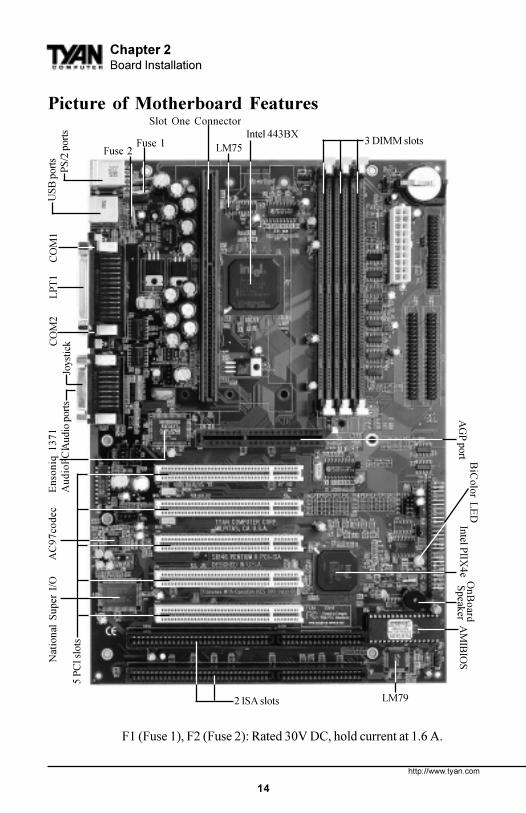
Picture of Motherboard Features
Fuse 1Fuse 2
F1 (Fuse 1), F2 (Fuse 2): Rated 30V DC, hold current at 1.6 A.
S1846 Tsunami ATX
15
INS
TAL
L
1. Setting Jumpers
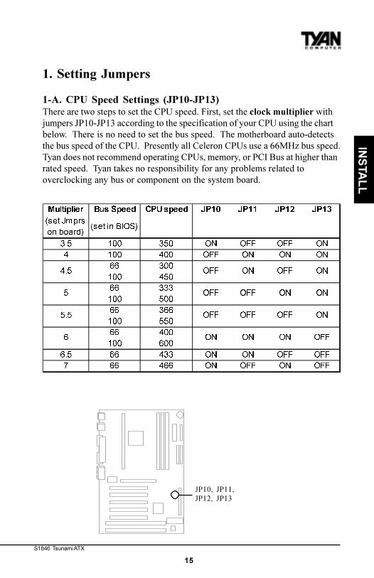
1-A. CPU Speed Settings (JP10-JP13)There are two steps to set the CPU speed. First, set the clock multiplier withjumpers JP10-JP13 according to the specification of your CPU using the chartbelow. There is no need to set the bus speed. The motherboard auto-detectsthe bus speed of the CPU. Presently all Celeron CPUs use a 66MHz bus speed.Tyan does not recommend operating CPUs, memory, or PCI Bus at higher thanrated speed. Tyan takes no responsibility for any problems related tooverclocking any bus or component on the system board.
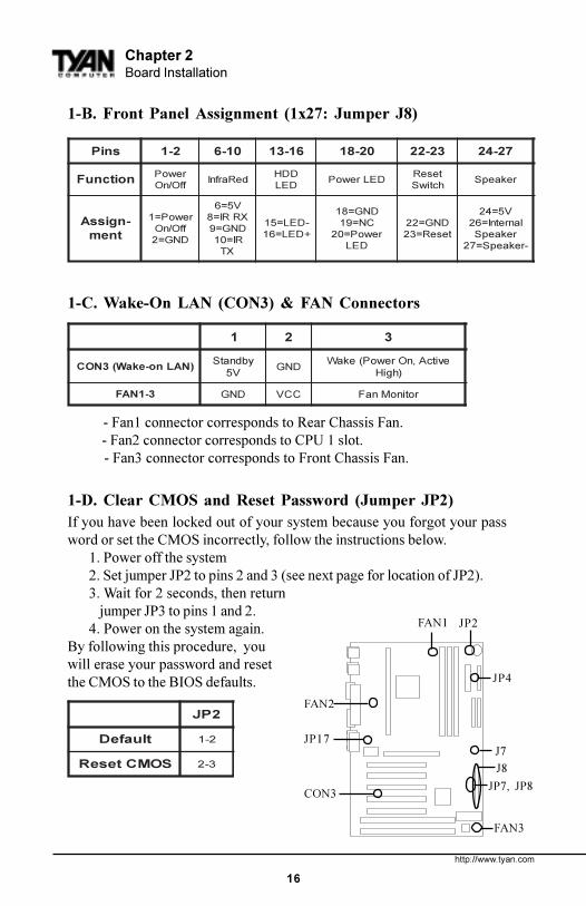
- Fan1 connector corresponds to Rear Chassis Fan. - Fan2 connector corresponds to CPU 1 slot. - Fan3 connector corresponds to Front Chassis Fan.
1-D. Clear CMOS and Reset Password (Jumper JP2)If you have been locked out of your system because you forgot your password or set the CMOS incorrectly, follow the instructions below.
1. Power off the system2. Set jumper JP2 to pins 2 and 3 (see next page for location of JP2).3. Wait for 2 seconds, then return
jumper JP3 to pins 1 and 2.4. Power on the system again.
By following this procedure, youwill erase your password and resetthe CMOS to the BIOS defaults.
2PJ
tluafeD 2-1
SOMCteseR 3-2
JP7, JP8
JP4
J8
JP2
FAN3
FAN1
FAN2
CON3
JP17J7
S1846 Tsunami ATX
17
INS
TAL
L
1-E. IR/FloppySet to 2 FDD if you are using 2 floppy drives.
DDF/RI 4PJ 7PJ 8PJ
DDF2 NO 3-2 2-1
)tluafeD(DDF1/RI1 FFO 2-1 3-2
1-F. Onboard Sound Enable (S1846SLA only)
dnuoS 71PJ
elbanE FFO
elbasiD NO
1-G. Chassis Intrusion Alarm ConnectorThe J7 connector is an intrusion alarm, that can be connected to the systemchassis. When active (J7 is closed), this alarm will alert the system administra-tor anytime someone opens the system�s case.
Soft Power ConnectorThe Soft Power Connector is pins 1-2 of jumper block J8. The Tsunami ATXuses the chipset for power management, including turning on and off thesystem. If the Power Button Function option in the BIOS Power ManagementMenu is set to On/Off (which is the default), pressing the power button onceafter the BIOS has booted up will turn the system on and off. If the PowerButton Function option is set to Suspend, pressing the power button once willwake the system or send it to Suspend mode. In this case, you cannot turn thesystem off unless you shut down through the Windows operating system oryou hold the power button down for four seconds.
Hardware Reset Switch Connector InstallationThe Reset switch on your case�s display panel provides you with the Hard-ware Reset function, which is the same as power on/off. The system will do acold start after the Reset button is pushed.
http://www.tyan.com
18
Chapter 2Board Installation
!important!
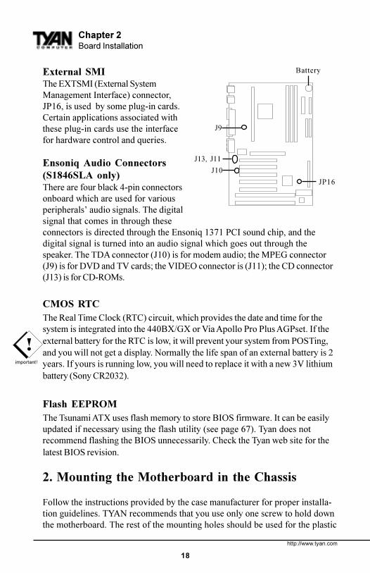
External SMIThe EXTSMI (External SystemManagement Interface) connector,JP16, is used by some plug-in cards.Certain applications associated withthese plug-in cards use the interfacefor hardware control and queries.
Ensoniq Audio Connectors(S1846SLA only)There are four black 4-pin connectorsonboard which are used for variousperipherals� audio signals. The digitalsignal that comes in through theseconnectors is directed through the Ensoniq 1371 PCI sound chip, and thedigital signal is turned into an audio signal which goes out through thespeaker. The TDA connector (J10) is for modem audio; the MPEG connector(J9) is for DVD and TV cards; the VIDEO connector is (J11); the CD connector(J13) is for CD-ROMs.
CMOS RTCThe Real Time Clock (RTC) circuit, which provides the date and time for thesystem is integrated into the 440BX/GX or Via Apollo Pro Plus AGPset. If theexternal battery for the RTC is low, it will prevent your system from POSTing,and you will not get a display. Normally the life span of an external battery is 2years. If yours is running low, you will need to replace it with a new 3V lithiumbattery (Sony CR2032).
Flash EEPROMThe Tsunami ATX uses flash memory to store BIOS firmware. It can be easilyupdated if necessary using the flash utility (see page 67). Tyan does notrecommend flashing the BIOS unnecessarily. Check the Tyan web site for thelatest BIOS revision.
2. Mounting the Motherboard in the Chassis
Follow the instructions provided by the case manufacturer for proper installa-tion guidelines. TYAN recommends that you use only one screw to hold downthe motherboard. The rest of the mounting holes should be used for the plastic
J10
J13, J11
J9
Battery
JP16
S1846 Tsunami ATX
19
INS
TAL
L
standoffs. If your case does not have a hole for a standoff, simply cut off thebottom of the plastic standoff so that the flat portion rests on the metal. Theadapter cards and the screws holding them down will keep your board flat. Thefastening screw should not short any of the traces on the motherboard. Makecertain that you do not overtighten the screw, as it will damage the mother-board and possibly break internal traces in the surrounding area. The hole youshould use is located at the top-center of the board where the adapter cardsare fastened to the case.
3. Installing Memory
Since TYAN boards are manufactured with performance in mind, you shoulduse add-in components that match. Some DIMM modules may seem to be highquality because of name or feel but that does not guarantee real-worldusability. Some cheaper or OEM memory may have brand-name components,but they may contain inferior or substandard parts which do not meet thecritical tolerances our products require. Because of this, your memory may notwork correctly in a TYAN board though it may work well in a competitor�sboard. This is because many of our competitors do not adhere to the stricttolerances required for high performance. If you buy a TYAN board, you aregetting the best system available. To make installation easy and trouble free,get high quality parts. Some brands we recommend are Corsair Microsystems,Kingston Memory, and QesTec Incorporated. These DIMMs have proven tobe very stable on our boards and perform extremely well.
http://www.tyan.com
20
Chapter 2Board Installation
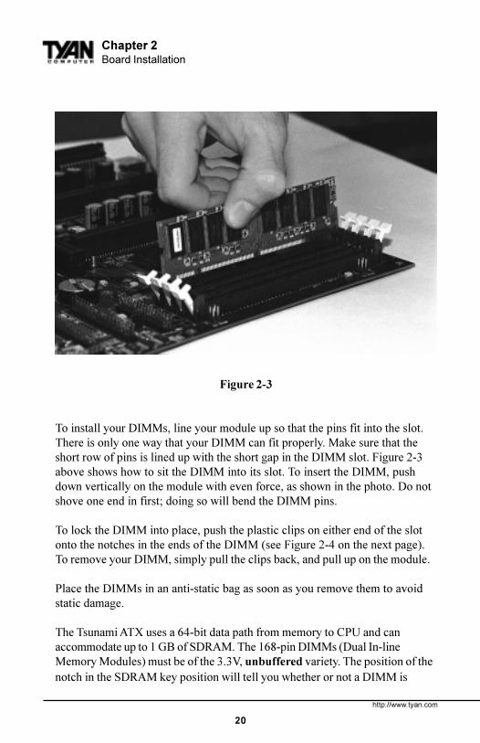
Figure 2-3
To install your DIMMs, line your module up so that the pins fit into the slot.There is only one way that your DIMM can fit properly. Make sure that theshort row of pins is lined up with the short gap in the DIMM slot. Figure 2-3above shows how to sit the DIMM into its slot. To insert the DIMM, pushdown vertically on the module with even force, as shown in the photo. Do notshove one end in first; doing so will bend the DIMM pins.
To lock the DIMM into place, push the plastic clips on either end of the slotonto the notches in the ends of the DIMM (see Figure 2-4 on the next page).To remove your DIMM, simply pull the clips back, and pull up on the module.
Place the DIMMs in an anti-static bag as soon as you remove them to avoidstatic damage.
The Tsunami ATX uses a 64-bit data path from memory to CPU and canaccommodate up to 1 GB of SDRAM. The 168-pin DIMMs (Dual In-lineMemory Modules) must be of the 3.3V, unbuffered variety. The position of thenotch in the SDRAM key position will tell you whether or not a DIMM is
S1846 Tsunami ATX
21
INS
TAL
L
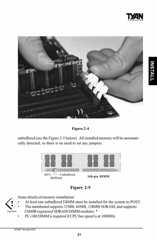
Figure 2-4
unbuffered (see the Figure 2-5 below). All installed memory will be automati-cally detected, so there is no need to set any jumpers.
Figure 2-5
Some details of memory installation:� At least one unbuffered DIMM must be installed for the system to POST.� The mainboard supports 32MB, 64MB, 128MB SDRAM; and supports 256MB registered SDRAM DIMM modules. *� PC-100 DIMM is required if CPU bus speed is at 100MHz
!important!
RFUBuffered
Unbuffered168-pin DIMM
http://www.tyan.com
22
Chapter 2Board Installation
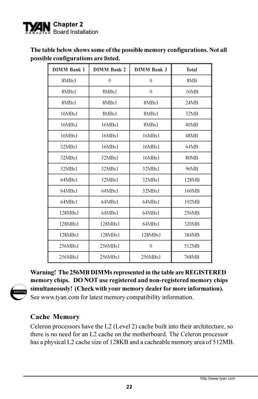
The table below shows some of the possible memory configurations. Not allpossible configurations are listed.
Warning! The 256MB DIMMs represented in the table are REGISTEREDmemory chips. DO NOT use registered and non-registered memory chipssimultaneously! (Check with your memory dealer for more information).See www.tyan.com for latest memory compatibility information.
Cache MemoryCeleron processors have the L2 (Level 2) cache built into their architecture, sothere is no need for an L2 cache on the motherboard. The Celeron processorhas a physical L2 cache size of 128KB and a cacheable memory area of 512MB.
1knaBMMID 2knaBMMID 3knaBMMID latoT
1xBM8 0 0 BM8
1xBM8 1xBM8 0 BM61
1xBM8 1xBM8 1xBM8 BM42
1xBM61 1xBM8 1xBM8 BM23
1xBM61 1xBM61 1xBM8 BM04
1xBM61 1xBM61 1xBM61 BM84
1xBM23 1xBM61 1xBM61 BM46
1xBM23 1xBM23 1xBM61 BM08
1xBM23 1xBM23 1xBM23 BM69
1xBM46 1xBM23 1xBM23 BM821
1xBM46 1xBM46 1xBM23 BM061
1xBM46 1xBM46 1xBM46 BM291
1xBM821 1xBM46 1xBM46 BM652
1xBM821 1xBM821 1xBM46 BM023
1xBM821 1xBM821 1xBM821 BM483
1xBM652 1xBM652 0 BM215
1xBM652 1xBM652 1xBM652 BM867
warning
S1846 Tsunami ATX
23
INS
TAL
L
4. Installing the CPU and Cooling Fan
Pentium II or Pentium III processors (233 through 500MHz) can be used on theTsunami ATX. Please refer to page 15 for the correct CPU jumper settings foryour board. Remember:• The CPU is a sensitive electronic component and it can easily be damaged
by static electricity. Do not touch the CPU pins with your fingers.• Before the CPU is installed, the motherboard must be placed on a
flat surface. You should be able to insert the CPU with minimal, butfirm, pressure. Do not press down hard on the CPU.
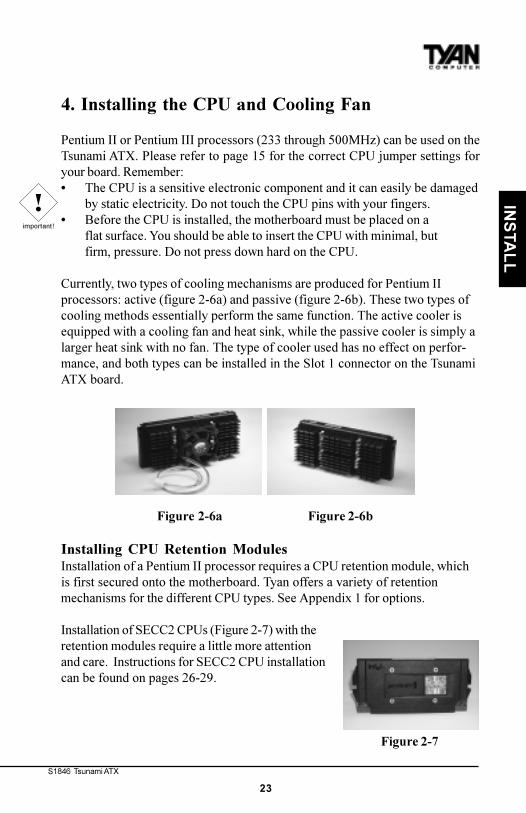
Currently, two types of cooling mechanisms are produced for Pentium IIprocessors: active (figure 2-6a) and passive (figure 2-6b). These two types ofcooling methods essentially perform the same function. The active cooler isequipped with a cooling fan and heat sink, while the passive cooler is simply alarger heat sink with no fan. The type of cooler used has no effect on perfor-mance, and both types can be installed in the Slot 1 connector on the TsunamiATX board.
Figure 2-6a Figure 2-6b
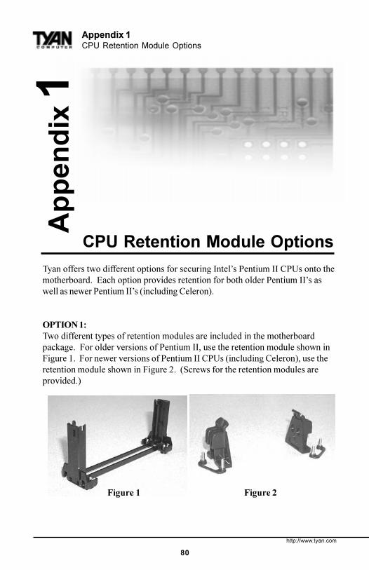
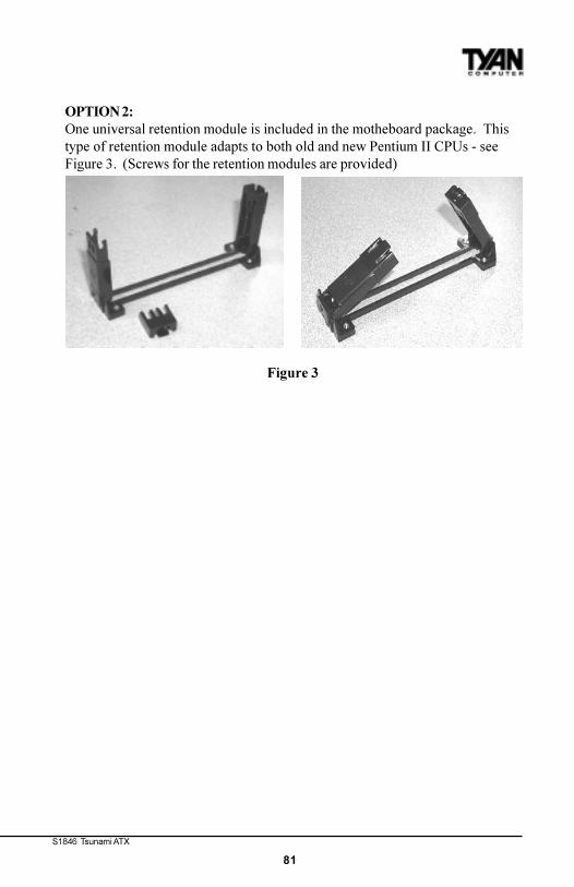
Installing CPU Retention ModulesInstallation of a Pentium II processor requires a CPU retention module, whichis first secured onto the motherboard. Tyan offers a variety of retentionmechanisms for the different CPU types. See Appendix 1 for options.
Installation of SECC2 CPUs (Figure 2-7) with theretention modules require a little more attentionand care. Instructions for SECC2 CPU installationcan be found on pages 26-29.
!important!
Figure 2-7
http://www.tyan.com
24
Chapter 2Board Installation
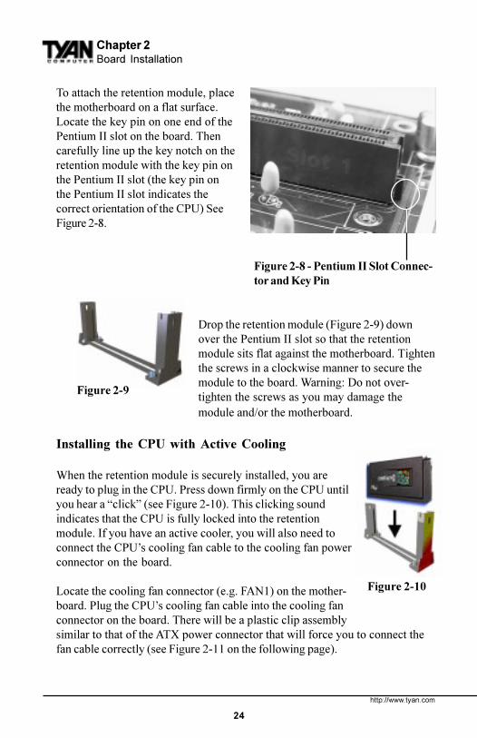
To attach the retention module, placethe motherboard on a flat surface.Locate the key pin on one end of thePentium II slot on the board. Thencarefully line up the key notch on theretention module with the key pin onthe Pentium II slot (the key pin onthe Pentium II slot indicates thecorrect orientation of the CPU) SeeFigure 2-8.
Drop the retention module (Figure 2-9) downover the Pentium II slot so that the retentionmodule sits flat against the motherboard. Tightenthe screws in a clockwise manner to secure themodule to the board. Warning: Do not over-tighten the screws as you may damage themodule and/or the motherboard.
Installing the CPU with Active Cooling
When the retention module is securely installed, you areready to plug in the CPU. Press down firmly on the CPU untilyou hear a �click� (see Figure 2-10). This clicking soundindicates that the CPU is fully locked into the retentionmodule. If you have an active cooler, you will also need toconnect the CPU�s cooling fan cable to the cooling fan powerconnector on the board.
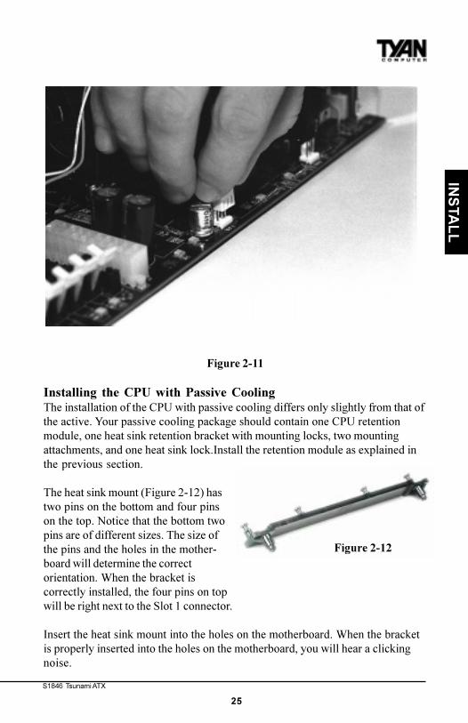
Locate the cooling fan connector (e.g. FAN1) on the mother-board. Plug the CPU�s cooling fan cable into the cooling fanconnector on the board. There will be a plastic clip assemblysimilar to that of the ATX power connector that will force you to connect thefan cable correctly (see Figure 2-11 on the following page).
Figure 2-8 - Pentium II Slot Connec-tor and Key Pin
Figure 2-9
Figure 2-10
S1846 Tsunami ATX
25
INS
TAL
L
Figure 2-11
Installing the CPU with Passive CoolingThe installation of the CPU with passive cooling differs only slightly from that ofthe active. Your passive cooling package should contain one CPU retentionmodule, one heat sink retention bracket with mounting locks, two mountingattachments, and one heat sink lock.Install the retention module as explained inthe previous section.
The heat sink mount (Figure 2-12) hastwo pins on the bottom and four pinson the top. Notice that the bottom twopins are of different sizes. The size ofthe pins and the holes in the mother-board will determine the correctorientation. When the bracket iscorrectly installed, the four pins on topwill be right next to the Slot 1 connector.
Insert the heat sink mount into the holes on the motherboard. When the bracketis properly inserted into the holes on the motherboard, you will hear a clickingnoise.
Figure 2-12
http://www.tyan.com
26
Chapter 2Board Installation
Align the CPU with the CPU retention module. Make sure the heat sink is linedup with the heat sink mount bracket. If you put the CPU in the wrong way, youmay damage the CPU, the motherboard, and/or the CPU socket. Slowly pressdown on the CPU module until the CPU locks into place. You will hear a clickingnoise when the CPU is locked securely into the module.
The heat sink lock (Figure 2-13) has fournotches which will correspond to the fourpins on the heat sink mounting bracket.Gently slide the lock between the heatsink and the heat sink mounting bracketuntil both sides of the lock are firmlysecured. A clicking sound will be heard when the lock is securely fastened to theheat sink mounting bracket. To remove the lock from the heat sink mountingbracket, gently press the ends of the locks inward and pull.
Lock the heat sink mount to the board by inserting the twomounting locks (Figure 2-14) into the pins of the heat sinkmounting bracket which are now below the mainboard.There will be a click when the locks are securely fastened.
Removing the CPU.To remove the CPU, move the locks to the center of theCPU. A click will be heard when the CPU has been unlocked. Gently pull up onthe CPU, taking care not to bend the motherboard or the CPU retention module.
To remove the lock from the retention module, gently press the ends of the locksinward and pull.
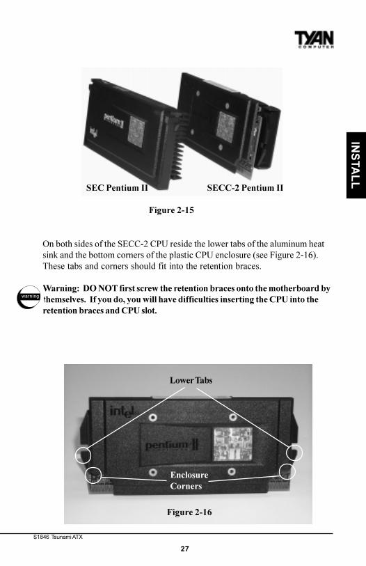
Installing SECC2 CPUsThe major physical difference between original Pentium II�s (SEC)and newPentium II/P-III (SECC-2) is the plastic CPU enclosure. As Figure 2-15 indicates,the plastic CPU enclosure covers the entire CPU card of regular Pentium II�s. Onthe other hand, the plastic CPU enclosure covers only the side faces of theSECC2 Pentium II card.
Due to the physical differences in the SECC2 CPU, installing the retentionmodules requires a different technique than the ones previously discussed.
Figure 2-13
Figure 2-14
S1846 Tsunami ATX
27
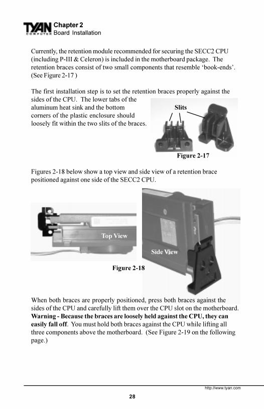
On both sides of the SECC-2 CPU reside the lower tabs of the aluminum heatsink and the bottom corners of the plastic CPU enclosure (see Figure 2-16).These tabs and corners should fit into the retention braces.
Warning: DO NOT first screw the retention braces onto the motherboard bythemselves. If you do, you will have difficulties inserting the CPU into theretention braces and CPU slot.
SEC Pentium II SECC-2 Pentium II
Figure 2-15
Lower Tabs
EnclosureCorners
Figure 2-16
warning
INS
TAL
L
http://www.tyan.com
28
Chapter 2Board Installation
Currently, the retention module recommended for securing the SECC2 CPU(including P-III & Celeron) is included in the motherboard package. Theretention braces consist of two small components that resemble �book-ends�.(See Figure 2-17 )
The first installation step is to set the retention braces properly against thesides of the CPU. The lower tabs of thealuminum heat sink and the bottom Slitscorners of the plastic enclosure shouldloosely fit within the two slits of the braces.
Figure 2-17
Figures 2-18 below show a top view and side view of a retention bracepositioned against one side of the SECC2 CPU.
Top View
Side View
Figure 2-18
When both braces are properly positioned, press both braces against thesides of the CPU and carefully lift them over the CPU slot on the motherboard.Warning - Because the braces are loosely held against the CPU, they caneasily fall off. You must hold both braces against the CPU while lifting allthree components above the motherboard. (See Figure 2-19 on the followingpage.)
S1846 Tsunami ATX
29
INS
TAL
L
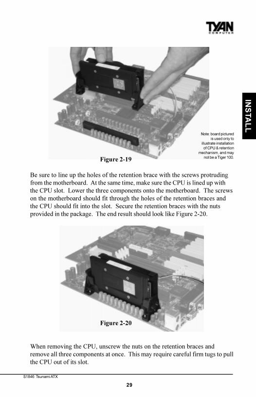
Figure 2-19
Be sure to line up the holes of the retention brace with the screws protrudingfrom the motherboard. At the same time, make sure the CPU is lined up withthe CPU slot. Lower the three components onto the motherboard. The screwson the motherboard should fit through the holes of the retention braces andthe CPU should fit into the slot. Secure the retention braces with the nutsprovided in the package. The end result should look like Figure 2-20.
Figure 2-20
When removing the CPU, unscrew the nuts on the retention braces andremove all three components at once. This may require careful firm tugs to pullthe CPU out of its slot.
Note: board picturedis used only to
illustrate installationof CPU & retention
mechanism, and maynot be a Tiger 100.
http://www.tyan.com
30
Chapter 2Board Installation
5. Connecting IDE and Floppy Drives
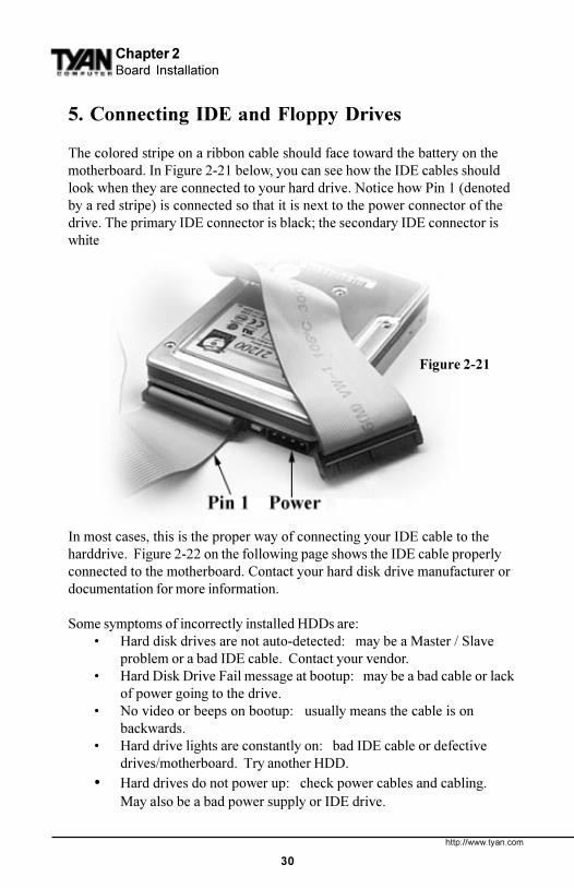
The colored stripe on a ribbon cable should face toward the battery on themotherboard. In Figure 2-21 below, you can see how the IDE cables shouldlook when they are connected to your hard drive. Notice how Pin 1 (denotedby a red stripe) is connected so that it is next to the power connector of thedrive. The primary IDE connector is black; the secondary IDE connector iswhite.
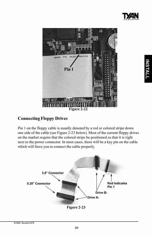
In most cases, this is the proper way of connecting your IDE cable to theharddrive. Figure 2-22 on the following page shows the IDE cable properlyconnected to the motherboard. Contact your hard disk drive manufacturer ordocumentation for more information.
Some symptoms of incorrectly installed HDDs are:� Hard disk drives are not auto-detected: may be a Master / Slave
problem or a bad IDE cable. Contact your vendor.� Hard Disk Drive Fail message at bootup: may be a bad cable or lack
of power going to the drive.� No video or beeps on bootup: usually means the cable is on
backwards.� Hard drive lights are constantly on: bad IDE cable or defective
drives/motherboard. Try another HDD.� Hard drives do not power up: check power cables and cabling.
May also be a bad power supply or IDE drive.
Figure 2-21
S1846 Tsunami ATX
31
INS
TAL
L
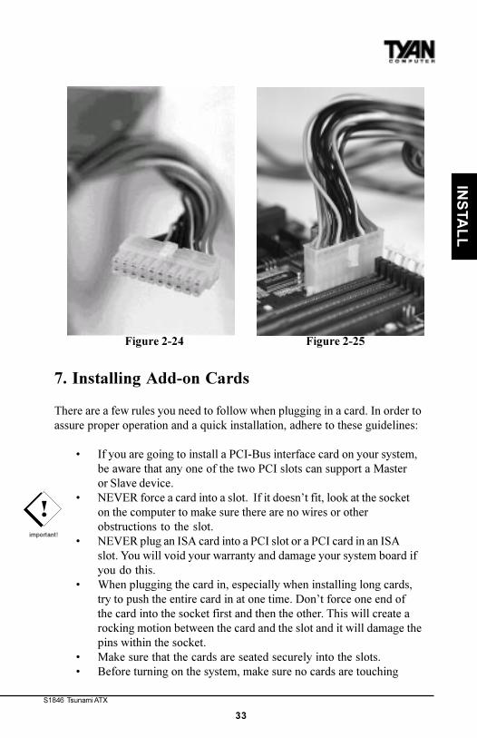
Connecting Floppy Drives
Pin 1 on the floppy cable is usually denoted by a red or colored stripe downone side of the cable (see Figure 2-23 below). Most of the current floppy driveson the market require that the colored stripe be positioned so that it is rightnext to the power connector. In most cases, there will be a key pin on the cablewhich will force you to connect the cable properly.
Figure 2-23
Figure 2-22
Pin 1
http://www.tyan.com
32
Chapter 2Installation
Drive A: is usually attached to the end of the cable with the twist in it. Drive B:is usually connected to the middle of the cable. Refer to your installationinstructions or call your dealer if you are unsure about attaching floppy drives.Refer to Figure 2-23 for a detailed anatomy of the floppy cable. Remember, youcan only have 2 floppy drives connected at any given time.
The color stripe on the cable should face toward the top of your chassis, ortoward the big white B printed on the motherboard. Please refer to yourdocumentation for proper installation.
Some symptoms of incorrectly installed floppies are:� Floppy drives are not detected: usually caused by faulty cables,
backward cables, or a bad floppy or motherboard. Try another singlefloppy drive to verify the problem or try another cable. Also, check tosee if the onboard floppy is enabled in the BIOS.
� Floppy Drive Fail message at bootup: the cable, floppy, ormotherboard may be faulty. Try another cable or floppy drive toverify.
� Light on the floppy is on constantly: a dead giveaway that the cableis on backwards. Reverse the cable at the motherboard end and tryagain.
6. Connecting the Power Supply
Tyan recommends using an ATX power supply that conforms to industrystandard revision 2.01. The Tomahawk BX/A+ motherboard comes equippedwith one onboard power connector.
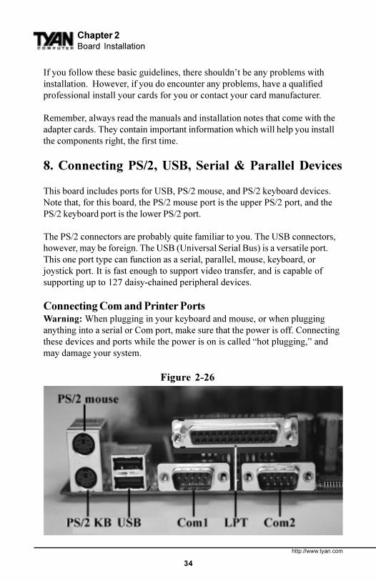
Figure 2-24 on the following page shows an ATX power connector. Whenplugging in the power connector, make sure that the plastic clip on the powerconnector is aligned with the plastic tab on the onboard connector (see Figure2-25 on the following page).
Make certain that you do not miss any pins because if you do, you will voidyour warranty and cause damage to yourself or your motherboard when youturn the system on. After connecting the power, make sure the connector isseated firmly into its socket so it will not become loose or fall off when thecomputer is jostled or moved.
warning
S1846 Tsunami ATX
33
INS
TAL
L
Figure 2-24 Figure 2-25
7. Installing Add-on Cards
There are a few rules you need to follow when plugging in a card. In order toassure proper operation and a quick installation, adhere to these guidelines:
� If you are going to install a PCI-Bus interface card on your system,be aware that any one of the two PCI slots can support a Masteror Slave device.
� NEVER force a card into a slot. If it doesn�t fit, look at the socketon the computer to make sure there are no wires or otherobstructions to the slot.
� NEVER plug an ISA card into a PCI slot or a PCI card in an ISAslot. You will void your warranty and damage your system board ifyou do this.
� When plugging the card in, especially when installing long cards,try to push the entire card in at one time. Don�t force one end ofthe card into the socket first and then the other. This will create arocking motion between the card and the slot and it will damage thepins within the socket.
� Make sure that the cards are seated securely into the slots.� Before turning on the system, make sure no cards are touching
!important!
http://www.tyan.com
34
If you follow these basic guidelines, there shouldn�t be any problems withinstallation. However, if you do encounter any problems, have a qualifiedprofessional install your cards for you or contact your card manufacturer.
Remember, always read the manuals and installation notes that come with theadapter cards. They contain important information which will help you installthe components right, the first time.
8. Connecting PS/2, USB, Serial & Parallel Devices
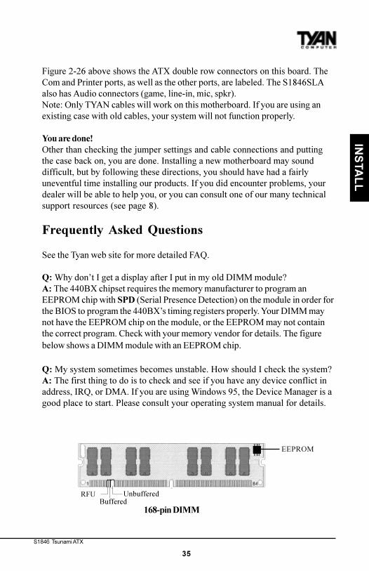
This board includes ports for USB, PS/2 mouse, and PS/2 keyboard devices.Note that, for this board, the PS/2 mouse port is the upper PS/2 port, and thePS/2 keyboard port is the lower PS/2 port.
The PS/2 connectors are probably quite familiar to you. The USB connectors,however, may be foreign. The USB (Universal Serial Bus) is a versatile port.This one port type can function as a serial, parallel, mouse, keyboard, orjoystick port. It is fast enough to support video transfer, and is capable ofsupporting up to 127 daisy-chained peripheral devices.
Connecting Com and Printer PortsWarning: When plugging in your keyboard and mouse, or when plugginganything into a serial or Com port, make sure that the power is off. Connectingthese devices and ports while the power is on is called �hot plugging,� andmay damage your system.
Chapter 2Board Installation
Figure 2-26
S1846 Tsunami ATX
35
RFUBuffered
Unbuffered
168-pin DIMM
EEPROM
Figure 2-26 above shows the ATX double row connectors on this board. TheCom and Printer ports, as well as the other ports, are labeled. The S1846SLAalso has Audio connectors (game, line-in, mic, spkr).Note: Only TYAN cables will work on this motherboard. If you are using anexisting case with old cables, your system will not function properly.
You are done!Other than checking the jumper settings and cable connections and puttingthe case back on, you are done. Installing a new motherboard may sounddifficult, but by following these directions, you should have had a fairlyuneventful time installing our products. If you did encounter problems, yourdealer will be able to help you, or you can consult one of our many technicalsupport resources (see page 8).
Frequently Asked Questions
See the Tyan web site for more detailed FAQ.
Q: Why don�t I get a display after I put in my old DIMM module?A: The 440BX chipset requires the memory manufacturer to program anEEPROM chip with SPD (Serial Presence Detection) on the module in order forthe BIOS to program the 440BX�s timing registers properly. Your DIMM maynot have the EEPROM chip on the module, or the EEPROM may not containthe correct program. Check with your memory vendor for details. The figurebelow shows a DIMM module with an EEPROM chip.
Q: My system sometimes becomes unstable. How should I check the system?A: The first thing to do is to check and see if you have any device conflict inaddress, IRQ, or DMA. If you are using Windows 95, the Device Manager is agood place to start. Please consult your operating system manual for details.
INS
TAL
L
http://www.tyan.com
36
Chapter 3BIOS Configuration
chap
ter 3
BIOS Configuration
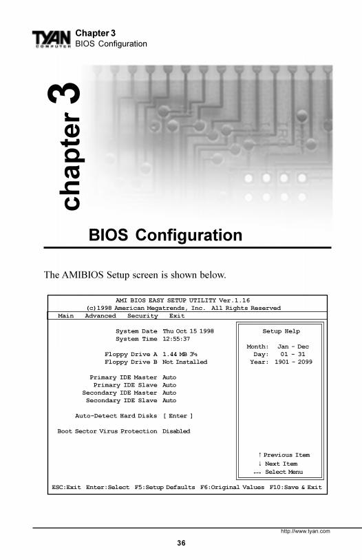
The AMIBIOS Setup screen is shown below.
AMI BIOS EASY SETUP UTILITY Ver.1.16 (c)1998 American Megatrends, Inc. All Rights Reserved Main Advanced Security Exit
System Date Thu Oct 15 1998 Setup Help System Time 12:55:37
Month: Jan - Dec Floppy Drive A 1.44 MB 3½ Day: 01 - 31 Floppy Drive B Not Installed Year: 1901 - 2099
Primary IDE Master Auto Primary IDE Slave Auto Secondary IDE Master Auto Secondary IDE Slave Auto
You can select a Setup option by using the following keyboard keys:
The pages which follow contain explanations of the settings for the AMIBIOSSetup menus. Drawings have been included for ease of reference. Overall, theAMIBIOS Setup program is easy to use, and fairly intuitive. Note that thegraphics in the manual are simpler than those that appear on your screen.
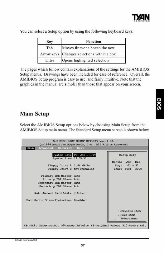
Main Setup
Select the AMIBIOS Setup options below by choosing Main Setup from theAMIBIOS Setup main menu. The Standard Setup menu screen is shown below.
AMI BIOS EASY SETUP UTILITY Ver.1.16 (c)1998 American Megatrends, Inc. All Rights Reserved Main Advanced Security Exit
System Date Fri Jan 1 1999 Setup Help System Time 12:55:37
Month: Jan - Dec Floppy Drive A 1.44 MB 3½ Day: 01 - 31 Floppy Drive B Not Installed Year: 1901 - 2099
Primary IDE Master Auto Primary IDE Slave Auto Secondary IDE Master Auto Secondary IDE Slave Auto
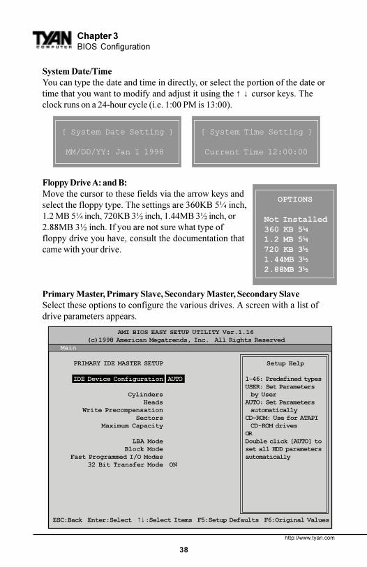
System Date/TimeYou can type the date and time in directly, or select the portion of the date ortime that you want to modify and adjust it using the ↑ ↓ cursor keys. Theclock runs on a 24-hour cycle (i.e. 1:00 PM is 13:00).
Floppy Drive A: and B:Move the cursor to these fields via the arrow keys andselect the floppy type. The settings are 360KB 5¼ inch,1.2 MB 5¼ inch, 720KB 3½ inch, 1.44MB 3½ inch, or2.88MB 3½ inch. If you are not sure what type offloppy drive you have, consult the documentation thatcame with your drive.
Primary Master, Primary Slave, Secondary Master, Secondary SlaveSelect these options to configure the various drives. A screen with a list ofdrive parameters appears.
[ System Date Setting ]
MM/DD/YY: Jan 1 1998
[ System Time Setting ]
Current Time 12:00:00
OPTIONS
Not Installed360 KB 5¼1.2 MB 5¼720 KB 3½1.44MB 3½2.88MB 3½
AMI BIOS EASY SETUP UTILITY Ver.1.16 (c)1998 American Megatrends, Inc. All Rights Reserved Main
PRIMARY IDE MASTER SETUP Setup Help
IDE Device Configuration AUTO 1-46: Predefined typesUSER: Set Parameters
Cylinders by User Heads AUTO: Set Parameters Write Precompensation automatically Sectors CD-ROM: Use for ATAPI Maximum Capacity CD-ROM drives
OR LBA Mode Double click [AUTO] to Block Mode set all HDD parameters Fast Programmed I/O Modes automatically 32 Bit Transfer Mode ON
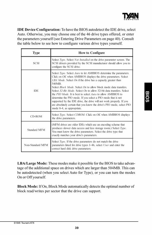
IDE Device Configuration: To have the BIOS autodetect the IDE drive, selectAuto. Otherwise, you may choose one of the 46 drive types offered, or enterthe parameters yourself (see Entering Drive Parameters on page 40). Consultthe table below to see how to configure various drive types yourself.
LBA/Large Mode: These modes make it possible for the BIOS to take advan-tage of the additional space on drives which are larger than 504MB. This canbe autodetected (when you select Auto for Type), or you can turn the modesOn or Off yourself.
Block Mode: If On, Block Mode automatically detects the optimal number ofblock read/writes per sector that the drive can support.
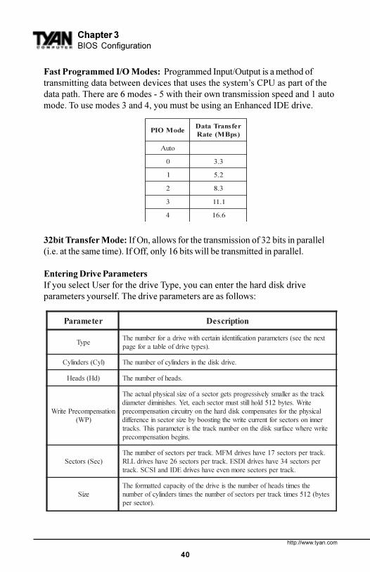
Fast Programmed I/O Modes: Programmed Input/Output is a method oftransmitting data between devices that uses the system�s CPU as part of thedata path. There are 6 modes - 5 with their own transmission speed and 1 automode. To use modes 3 and 4, you must be using an Enhanced IDE drive.
32bit Transfer Mode: If On, allows for the transmission of 32 bits in parallel(i.e. at the same time). If Off, only 16 bits will be transmitted in parallel.
Entering Drive ParametersIf you select User for the drive Type, you can enter the hard disk driveparameters yourself. The drive parameters are as follows:
Auto-Detect Hard DisksThis option lets the system detect your hard disk(s) automatically for yourconvenience.
Boot Sector Virus ProtectionThe available settings for this option are �Enable� and �Disable�.
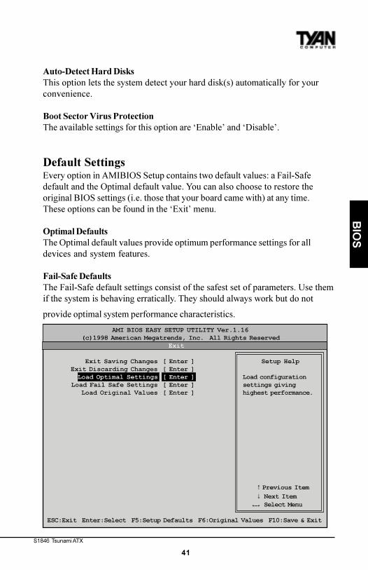
Default SettingsEvery option in AMIBIOS Setup contains two default values: a Fail-Safedefault and the Optimal default value. You can also choose to restore theoriginal BIOS settings (i.e. those that your board came with) at any time.These options can be found in the �Exit� menu.
Optimal DefaultsThe Optimal default values provide optimum performance settings for alldevices and system features.
Fail-Safe DefaultsThe Fail-Safe default settings consist of the safest set of parameters. Use themif the system is behaving erratically. They should always work but do not
provide optimal system performance characteristics.
→←
AMI BIOS EASY SETUP UTILITY Ver.1.16 (c)1998 American Megatrends, Inc. All Rights Reserved
Exit
Exit Saving Changes [ Enter ] Setup Help Exit Discarding Changes [ Enter ] Load Optimal Settings [ Enter ] Load configuration Load Fail Safe Settings [ Enter ] settings giving Load Original Values [ Enter ] highest performance.
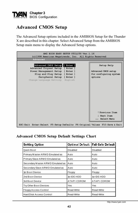
The Advanced Setup options included in the AMIBIOS Setup for the ThunderX are described in this chapter. Select Advanced Setup from the AMIBIOSSetup main menu to display the Advanced Setup options.
Advanced CMOS Setup Default Settings Chart
6HWWLQJ�2SWLRQ 2SWLPDO�'HIDXOW )DLO�6DIH�'HIDXOW
Quick Boot Disabled Disabled
Primary M aster ARM D Emulated as Auto Auto
Primary Slave ARM D Emulated as Auto Auto
Secondary M aster ARM D Emulated as Auto Auto
Secondary Slave ARM D Emulated as Auto Auto
1st Boot Device Floppy Floppy
2nd Boot Device 1st IDE-HDD 1st IDE-HDD
3rd Boot Device ATAPI CDROM ATAPI CDROM
Try Other Boot Devices Yes Yes
Floppy Access Control Read-Write Read-Write
Hard Disk Access Contro l Read-Write Read-Write
→←
AMI BIOS EASY SETUP UTILITY Ver.1.16 (c)1998 American Megatrends, Inc. All Rights Reserved Advanced
Advanced CMOS Setup [ Enter ] Setup Help Advanced Chipset Setup [ Enter ] Power Management Setup [ Enter ] Advanced CMOS setup Plug and Play Setup [ Enter ] for configuring system Peripheral Setup [ Enter ] options Change Language Setting English
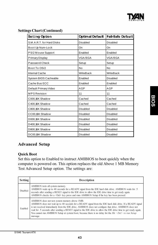
Quick BootSet this option to Enabled to instruct AMIBIOS to boot quickly when thecomputer is powered on. This option replaces the old Above 1 MB MemoryTest Advanced Setup option. The settings are:
Pri/Sec Master/Slave ARMD Emulated asATAPI Removable Media Disks (e.g. ZIP drives) are hybrid drives. They areremovable, and can be used as floppy drives, but also have great capacity andso are sometimes used as hard drives. These four options ensure that, if youhave an ARMD attached as a master or slave device, it can be properlydetected by the system. The settings are Auto, Floppy, and Hard Disk.
1st Boot DeviceThis option sets the type of device for the first boot drive that the AMIBIOSattempts to boot from after AMIBIOS POST completes. The settings areDisabled, 1st IDE-HDD, 2nd IDE-HDD, 3rd IDE-HDD, 4th IDE-HDD, Floppy,ARMD-FDD, ARMD-HDD, ATAPI CDROM, SCSI, NETWORK, and I
2O.
2nd Boot DeviceThis option sets the type of device for the second boot drive that theAMIBIOS attempts to boot from after AMIBIOS POST completes. Thesettings are Disabled, 1st IDE-HDD, 2nd IDE-HDD, 3rd IDE-HDD, 4th IDE-HDD, Floppy, ARMD-FDD, ARMD-HDD, ATAPI CDROM, and SCSI.
3rd Boot DeviceThis option sets the type of device for the third boot drive that the AMIBIOSattempts to boot from after AMIBIOS POST completes. The settings areDisabled, 1st IDE-HDD, 2nd IDE-HDD, 3rd IDE-HDD, 4th IDE-HDD, Floppy,ARMD-FDD, ARMD-HDD, ATAPI CDROM.
Try Other Boot DevicesSet this option to Yes to instruct AMIBIOS to attempt to boot from any otherdrive in the system if it cannot find a boot drive among the drives specified inthe 1st Boot Device, 2nd Boot Device, and 3rd Boot Device options. Thesettings are Yes or No.
Floppy Access ControlThis option specifies the read-write access that is set when booting from afloppy drive. The settings are Read-Write or Read-Only.
Hard Disk Access ControlThis option specifies the read-write access that is set when booting from ahard disk drive. The settings are Read-Write or Read-Only.
S.M.A.R.T. for Hard DisksSet this option to Enabled to permit AMIBIOS to use the SMART (System
S1846 Tsunami ATX
45
BIO
S
Management and Reporting Technologies) protocol for reporting serversystem information over a network. Enabling this feature allows you to back upyour data when your hard disk is about to fail. The settings are Enabled orDisabled.
Boot Up Num-LockSet this option to Off to turn the Num Lock key off when the computer isbooted so you can use the arrow keys on both the numeric keypad and thekeyboard. The settings are On or Off.
PS/2 Mouse SupportSet this option to Enabled to enable AMIBIOS support for a PS/2-type mouse.The BIOS will allocate IRQ12 for the PS/2 mouse. The settings are Enabled orDisabled.
Primary DisplayThis option configures the type of monitor attached to the computer. Thesettings are Absent, VGA/EGA, CGA40x25, CGA80x25, or Mono.
Password CheckThis option enables password checking every time the system boots or whenyou run AMIBIOS Setup. If Always is chosen, a user password promptappears every time the computer is turned on. If Setup is chosen, the passwordprompt appears if AMIBIOS is executed.
Boot To OS/2Set this option to Yes if you are running an OS/2 operating system and usingmore than 64 MB of system memory on the motherboard. The settings are Yesor No.
Internal CacheThis option sets the type of caching algorithm used by the L1 internal cachememory on the CPU. The settings are Disabled, WriteThru, or WriteBack.
System BIOS CacheableWhen set to Enabled, the contents of the F0000h system memory segment canbe read from or written to cache memory. The contents of this memory segmentare copied from the BIOS ROM to system RAM for faster execution. Thesettings are Enabled or Disabled. The Optimal default setting is Enabled.
http://www.tyan.com
46
Chapter 3BIOS Configuration
Cache Bus ECCWhen Enabled, this option permits ECC error checking on the L2 cache bus.This ensures that cached data is not improperly altered. The settings areEnabled or Disabled.
Default Primary VideoThis option sets the primary video card as either AGP (Accelerated GraphicsPort) card or a regular PCI video card. The settings are AGP or PCI.
MPS RevisionThis option sets the Multi-Processor Symmetry. Then settings are 1.1 or 1.4.
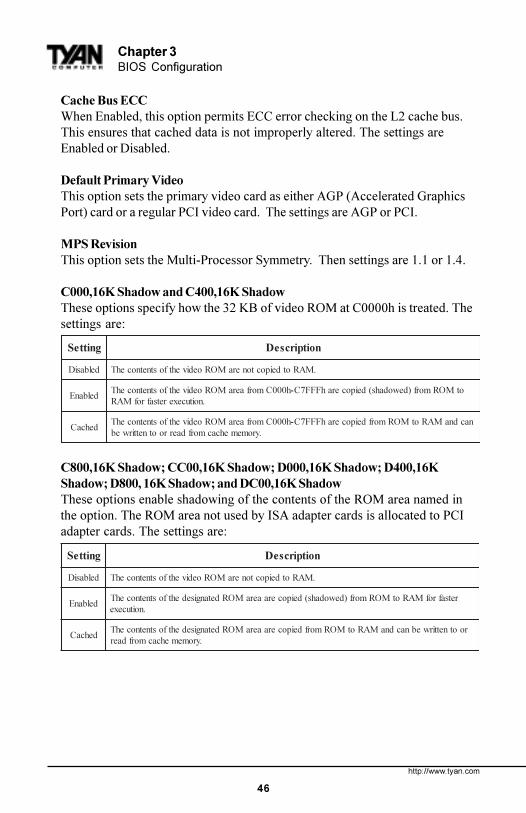
C000,16K Shadow and C400,16K ShadowThese options specify how the 32 KB of video ROM at C0000h is treated. Thesettings are:
C800,16K Shadow; CC00,16K Shadow; D000,16K Shadow; D400,16KShadow; D800, 16K Shadow; and DC00,16K ShadowThese options enable shadowing of the contents of the ROM area named inthe option. The ROM area not used by ISA adapter cards is allocated to PCIadapter cards. The settings are:
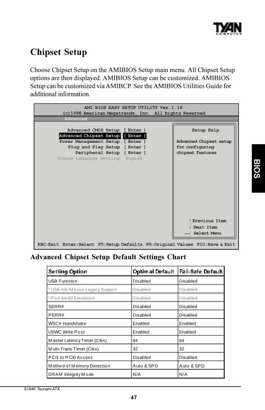
Choose Chipset Setup on the AMIBIOS Setup main menu. All Chipset Setupoptions are then displayed. AMIBIOS Setup can be customized. AMIBIOSSetup can be customized via AMIBCP. See the AMIBIOS Utilities Guide foradditional information.
Advanced Chipset Setup Default Settings Chart
→←
AMI BIOS EASY SETUP UTILITY Ver.1.16 (c)1998 American Megatrends, Inc. All Rights Reserved Advanced
Advanced CMOS Setup [ Enter ] Setup Help Advanced Chipset Setup [ Enter ] Power Management Setup [ Enter ] Advanced Chipset setup Plug and Play Setup [ Enter ] for configuring Peripheral Setup [ Enter ] chipset features Change Language Setting Engish
M ethod o f M emory Detection Auto & SPD Auto & SPD
DRAM Integrity M ode N/A N/A
http://www.tyan.com
48
Chapter 3BIOS Configuration
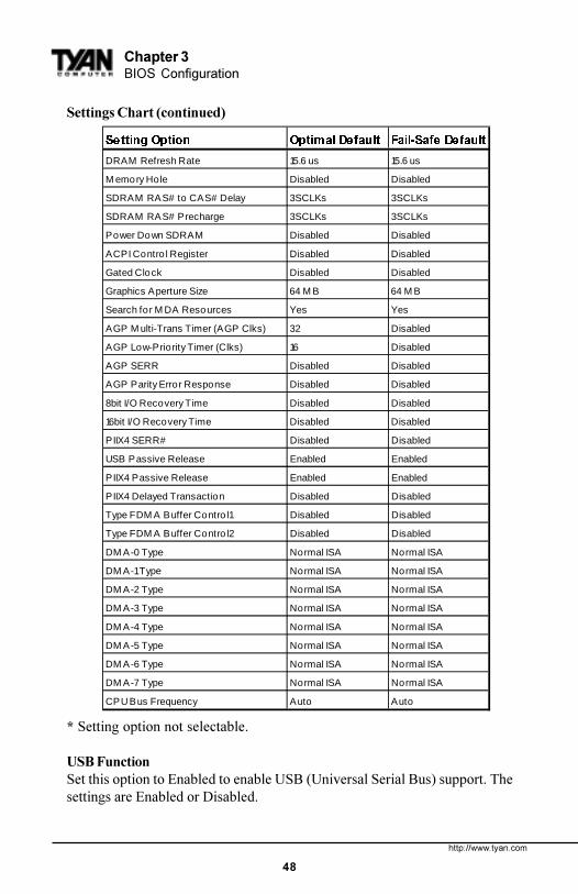
Settings Chart (continued)
* Setting option not selectable.
USB FunctionSet this option to Enabled to enable USB (Universal Serial Bus) support. Thesettings are Enabled or Disabled.
6HWWLQJ�2SWLRQ 2SWLPDO�'HIDXOW )DLO�6DIH�'HIDXOW
DRAM Refresh Rate 15.6 us 15.6 us
M emory Hole Disabled Disabled
SDRAM RAS# to CAS# Delay 3SCLKs 3SCLKs
SDRAM RAS# Precharge 3SCLKs 3SCLKs
Power Down SDRAM Disabled Disabled
ACPI Contro l Register Disabled Disabled
Gated Clock Disabled Disabled
Graphics Aperture Size 64 M B 64 M B
Search for M DA Resources Yes Yes
AGP M ulti-Trans Timer (AGP Clks) 32 Disabled
AGP Low-Priority Timer (Clks) 16 Disabled
AGP SERR Disabled Disabled
AGP Parity Error Response Disabled Disabled
8bit I/O Recovery Time Disabled Disabled
16bit I/O Recovery Time Disabled Disabled
PIIX4 SERR# Disabled Disabled
USB Passive Release Enabled Enabled
PIIX4 Passive Release Enabled Enabled
PIIX4 Delayed Transaction Disabled Disabled
Type FDM A Buffer Contro l1 Disabled Disabled
Type FDM A Buffer Contro l2 Disabled Disabled
DM A-0 Type Normal ISA Normal ISA
DM A-1 Type Normal ISA Normal ISA
DM A-2 Type Normal ISA Normal ISA
DM A-3 Type Normal ISA Normal ISA
DM A-4 Type Normal ISA Normal ISA
DM A-5 Type Normal ISA Normal ISA
DM A-6 Type Normal ISA Normal ISA
DM A-7 Type Normal ISA Normal ISA
CPU Bus Frequency Auto Auto
S1846 Tsunami ATX
49
BIO
S
USB KB/Mouse Legacy SupportSet this option to Enabled to enable support for older keyboards and mousedevices if the USB Function option is set to Enabled. The settings are Enabledor Disabled.
Port 64/60 EmulationSetting this option to Enabled allows a USB keyboard to act like a legacykeyboard. If this option is not Enabled, USB keyboard lights will not workunder Windows NT. With other operating systems, a USB keyboard will worknormally with this option Disabled. The settings are Enabled or Disabled.
SERR#Set this option to Enabled to enable the SERR# signal on the bus. The settingsare Enabled or Disabled.
PERR#Set this option to Enabled to enable the PERR# signal on the bus. The settingsare Enabled or Disabled. The Optimal and Fail-safe default settings areDisabled.
WSC# HandshakeSet this option to Enabled to enable handshaking for the WSC# signal.Handshaking is a form of encryption; see the Glossary for more information.The settings are Enabled or Disabled.
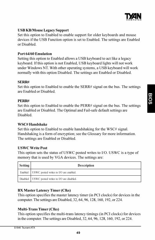
USWC Write PostThis option sets the status of USWC posted writes to I/O. USWC is a type ofmemory that is used by VGA devices. The settings are:
BX Master Latency Timer (Clks)This option specifies the master latency timer (in PCI clocks) for devices in thecomputer. The settings are Disabled, 32, 64, 96, 128, 160, 192, or 224.
Multi-Trans Timer (Clks)This option specifies the multi-trans latency timings (in PCI clocks) for devicesin the computer. The settings are Disabled, 32, 64, 96, 128, 160, 192, or 224.
gnitteS noitpircseD
delbanE .delbaneeraO/IotsetirwdetsopCWSU
delbasiD .delbasideraO/IotsetirwdetsopCWSU
http://www.tyan.com
50
Chapter 3BIOS Configuration
PCI1 to PCI0 AccessSet this option to Enabled to enable access between two different PCI buses(PCI1 and PCI0). The settings are Enabled or Disabled.
Method of Memory DetectionThis option determines how your system will detect the type of systemmemory you have installed. Options are Auto+SPD or Auto only.
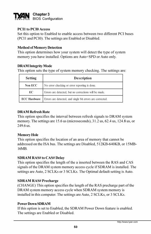
DRAM Integrity ModeThis option sets the type of system memory checking. The settings are:
DRAM Refresh RateThis option specifies the interval between refresh signals to DRAM systemmemory. The settings are 15.6 us (microseconds), 31.2 us, 62.4 us, 124.8 us, or249.6 us.
Memory HoleThis option specifies the location of an area of memory that cannot beaddressed on the ISA bus. The settings are Disabled, 512KB-640KB, or 15MB-16MB.
SDRAM RAS# to CAS# DelayThis option specifies the length of the a inserted between the RAS and CASsignals of the DRAM system memory access cycle if SDRAM is installed. Thesettings are Auto, 2 SCLKs or 3 SCLKs. The Optimal default setting is Auto.
SDRAM RAS# Precharge(CHANGE) This option specifies the length of the RAS precharge part of theDRAM system memory access cycle when SDRAM system memory isinstalled in this computer. The settings are Auto, 2 SCLKs, or 3 SCLKs.
Power Down SDRAMIf this option is set to Enabled, the SDRAM Power Down feature is enabled.The settings are Enabled or Disabled.
ACPI Control RegisterSet this option to Enabled to enable the ACPI (Advanced Configuration andPower Interface) control register. The settings are Enabled or Disabled. TheOptimal and Fail-safe default settings are Enabled.
Gated ClockSet this option to Enabled to enable the gated clock. The settings are Enabledor Disabled.
Graphics Aperture SizeThis option specifies the amount of system memory that can be used by theAccelerated Graphics Port (AGP). The settings are 4 MB, 8 MB, 16 MB, 32 MB,64 MB, 128 MB, or 256 MB.
Search for MDA ResourcesSet this option to Yes to let AMIBIOS search for MDA resources. The settingsare Yes or No.
AGP Multi-Trans Timer (AGP Clks)This option sets the AGP multi-trans timer. The settings are in units of AGPClocks. The settings are Disabled, 32, 64, 96, 128, 160, 192, or 224.
AGP Low-Priority Timer (Clks)This option sets the AGP low priority timer. The settings are in units of AGPClocks. The settings are Disabled, 16, 32, 48, 64, 80, 96, 112, 128, 144, 176, 192,208, 224, or 240.
AGP SERRSet this option to Enabled to enable the AGP SERR signal. The settings areEnabled or Disabled.
AGP Parity Error ResponseSet this option to Enabled to enable AGP parity error response. The settingsare Enabled or Disabled.
8bit I/O Recovery TimeThis option specifies the length of a delay inserted between consecutive 8-bitI/O operations. The settings are Disabled and from 1 to 8 Sysclk (systemclocks) in increments of one.
http://www.tyan.com
52
Chapter 3BIOS Configuration
16bit I/O Recovery TimeThis option specifies the length of a delay inserted between consecutive 16-bitI/O operations. The settings are Disabled and from 1 to 4 Sysclk (systemclocks) in increments of one.
PIIX4 SERR#Set this option to Enabled to enable the SERR# signal for the Intel PIIX4 chip.The settings are Enabled or Disabled.
USB Passive ReleaseSet this option to Enabled to enable passive release for USB. The settings areEnabled or Disabled.
PIIX4 Passive ReleaseSet this option to Enabled to enable passive release for the Intel PIIX4e chip.This option must be Enabled to provide PCI 2.1 compliance. The settings areEnabled or Disabled.
PIIX4 DELAYED TRANSACTIONSet this option to Enabled to enable delayed transactions for the Intel PIIX4chip. This option must be Enabled to provide PCI 2.1 compliance. The settingsare Enabled or Disabled.
TypeF DMA Buffer Control1 and 2These options specify the DMA channel where TypeF buffer control isimplemented. The settings are Disabled, Channel-0, Channel-1, Channel-2,Channel-3, Channel-5, Channel-6, or Channel-7.
DMA-n TypeThese options specify the bus that the specified DMA channel can be usedon. The settings are Normal ISA, PC/PCI, or Distributed.
CPU Bus FrequencyThis option provides selective CPU Bus Frequency; however, it is stronglyrecommended that the default setting (Auto) be selected. Unpredictablesituations may arise if the Intel default CPU bus speed is not used. Thesettings are Auto, 66.8MHz, 68.5MHz, 75MHz, 83.3MHz, 100MHz, 103MHz, or112MHz.
S1846 Tsunami ATX
53
BIO
S
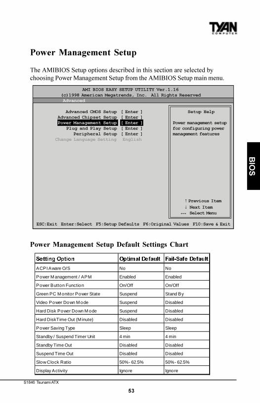
Power Management Setup
The AMIBIOS Setup options described in this section are selected bychoosing Power Management Setup from the AMIBIOS Setup main menu.
Power Management Setup Default Settings Chart
→←
AMI BIOS EASY SETUP UTILITY Ver.1.16 (c)1998 American Megatrends, Inc. All Rights Reserved Advanced
Advanced CMOS Setup [ Enter ] Setup Help Advanced Chipset Setup [ Enter ] Power Management Setup [ Enter ] Power management setup Plug and Play Setup [ Enter ] for configuring power Peripheral Setup [ Enter ] management features Change Language Setting English
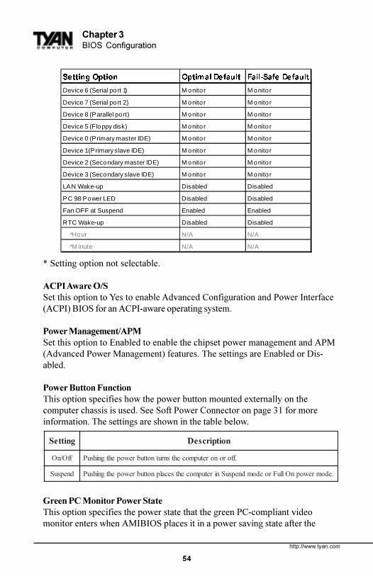
ACPI Aware O/SSet this option to Yes to enable Advanced Configuration and Power Interface(ACPI) BIOS for an ACPI-aware operating system.
Power Management/APMSet this option to Enabled to enable the chipset power management and APM(Advanced Power Management) features. The settings are Enabled or Dis-abled.
Power Button FunctionThis option specifies how the power button mounted externally on thecomputer chassis is used. See Soft Power Connector on page 31 for moreinformation. The settings are shown in the table below.
Green PC Monitor Power StateThis option specifies the power state that the green PC-compliant videomonitor enters when AMIBIOS places it in a power saving state after the
Device 2 (Secondary master IDE) M onito r M onito r
Device 3 (Secondary slave IDE) M onito r M onito r
LAN Wake-up Disabled Disabled
PC 98 Power LED Disabled Disabled
Fan OFF at Suspend Enabled Enabled
RTC Wake-up Disabled Disabled
*Hour N/A N/A
*M inute N/A N/A
S1846 Tsunami ATX
55
BIO
S
specified period of display inactivity has expired. The settings are Off, StandBy, or Suspend.
Video Power Down ModeThis option specifies the power state that the video subsystem enters whenAMIBIOS places it in a power saving state after the specified period of displayinactivity has expired. The settings are Stand By, Suspend, or Disabled.
Hard Disk Power Down ModeThis option specifies the power conserving state that the hard disk driveenters after the specified period of hard drive inactivity has expired. Thesettings are Disabled, Stand By, or Suspend.
Hard Disk Time Out (Minute)This option specifies the length of a period of hard disk drive inactivity. Whenthis length of time expires, the computer enters power-conserving statespecified in the Hard Disk Power Down Mode option (see above). The settingsare Disabled, and from 1 to 15 minutes, in one minute intervals.
Power Saving TypeThere are several types of sleeping states within the general sleep state. Thisoption allows you to choose how �asleep� you want your system to be. Indeeper sleep modes, more energy is saved. However, upon waking up, thesystem must �reorient� itself, and reestablish control over the system�ssleeping components. The settings are POS, Sleep, Stop Clock, and DeepSleep. POS is the lightest sleep mode; Deep Sleep is the heaviest.
Standby/Suspend Timer UnitThis option specifies the unit of time used for the Standby and Suspend timeout periods. The settings are 4 msec, 4 sec, 32 sec, or 4 min.
Standby Time OutThis option defines the length of time that the system, while in Full On state,must be inactive before it enters Standby mode. The settings are Disabled andfrom 4 minutes to 508 minutes, in increments of 4 minutes.
Suspend Time OutThis option defines the length of time that the system, while in Standby mode,must be inactive before it enters Suspend mode. The settings are Disabled andfrom 4 minutes to 508 minutes, in increments of 4 minutes.
http://www.tyan.com
56
Chapter 3BIOS Configuration
Slow Clock RatioThis option specifies the speed at which the system clock runs in the StandbyMode power saving state. The settings are expressed as a percentage of thenormal CPU clock speed. The settings are 0-12.5%, 12.5%-25%, 25%-37.5%,37.5%-50%, 50%-62.5%, 62.5%-75%, or 75-87.5%.
Display ActivityWhen set to Monitor, this option enables event monitoring on the videodisplay. If set to Monitor and the computer is in a power saving state, displayactivity will cause the system to enter the Full On state. AMIBIOS reloads theStandby and Suspend time-out timers if display activity occurs. The settingsare Monitor or Ignore.
Device n (Device identity)When set to Monitor, these options enable event monitoring on the specifiedhardware interrupt request line. If set to Monitor and the computer is in apower saving state, any activity on the IRQ line will cause the system to enterthe Full On state. AMIBIOS reloads the Standby and Suspend time-out timersif activity occurs on the specified IRQ line. The settings for each of theseoptions are Monitor or Ignore.
LAN Wake-upWhen this option is Enabled, the system will wake up when a signal isreceived on the Wake-on LAN header. In order for this wake up function towork, the system must have been brought up at least past the POST before itwas last shut down (i.e. if you turn the system off before the POST, theregistry will not be set, and the system will not be able to wake up using thisfunction). This function requires an ATX 2.01 compliant power supply with 5Vstandby (STB5V) current of at least 800mA. The settings are Enabled orDisabled.
PC98 Power LEDWhen this option is Enabled, your power LED will turn to yellow when yoursystem is in Suspend mode. Note that if you do not have a two-color LED,your LED will turn off when the system is in Suspend mode if this option is setto Enabled. The settings are Enabled or Disabled.
FAN OFF at SuspendIf this option is Enabled, the CPU fan will turn off when the system is inSuspend mode. If Disabled, the CPU fan will remain on while the system is inSuspend mode. The settings are Enabled or Disabled.
S1846 Tsunami ATX
57
BIO
S
RTC Wake-upIf Enabled, this option allows you to set an hour and minute for the system towake up. The next two fields allow you to choose the wake up time. Note thatthe time fields will not be available if this option is set to Disabled. In order forthis wake up function to work, the system must have been brought up at leastpast the POST before it was last shut down (i.e. if you turn the system offbefore the POST, the registry will not be set, and the system will not be able towake up using this function). The settings are Enabled or Disabled.
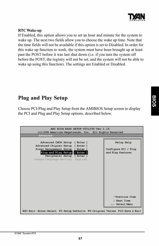
Plug and Play Setup
Choose PCI/Plug and Play Setup from the AMIBIOS Setup screen to displaythe PCI and Plug and Play Setup options, described below.
→←
AMI BIOS EASY SETUP UTILITY Ver.1.16 (c)1998 American Megatrends, Inc. All Rights Reserved Advanced
Advanced CMOS Setup [ Enter ] Setup Help Advanced Chipset Setup [ Enter ] Power Management Setup [ Enter ] Configure PCI / Plug Plug and Play Setup [ Enter ] and Play features Peripheral Setup [ Enter ] Change Language Setting English
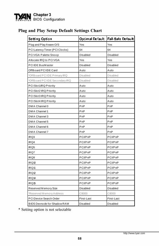
Plug and Play Aware O/SSet this option to Yes to inform AMIBIOS that the operating system canhandle plug and Play (PnP) devices. The settings are No or Yes.
PCI Latency Timer (PCI Clocks)This option specifies the latency timings (in PCI clocks) for PCI devicesinstalled in the PCI expansion slots. The settings are 32, 64, 96, 128, 160, 192,224, or 248.
PCI VGA Palette SnoopWhen this option is set to Enabled, multiple VGA devices operating ondifferent buses can handle data from the CPU on each set of palette registerson every video device. Bit 5 of the command register in the PCI deviceconfiguration space is the VGA Palette Snoop bit (0 is disabled). For example, ifthere are two VGA devices in the computer (one PCI and one ISA) and thisfield is set for:
This option must be set to Enabled if any ISA adapter card installed in thesystem requires VGA palette snooping.
Allocate IRQ to PCI VGASet this option to Yes to allocate an IRQ to the VGA device on the PCI bus.The settings are Yes or No.
PCI IDE BusMasterSet this option to Enabled to specify that the IDE controller on the PCI bus hasbus mastering capability. The settings are Disabled or Enabled.
OffBoard PCI IDE CardThis option specifies whether or not an offboard PCI IDE controller adaptercard is used in the computer, and where it is installed. If an offboard PCI IDEcontroller is used, the motherboard onboard IDE controller is automaticallydisabled. The settings are Auto and Slot1 through Slot6. If Auto is selected,AMIBIOS automatically determines the correct setting (including using theonboard controller if no offboard controller card is detected). This optionforces IRQ 14 and 15 to a PCI slot on the PCI local bus. This is necessary to
OffBoard PCI IDE Primary IRQThis option specifies the PCI interrupt used by the primary IDE channel on theoffboard PCI IDE controller. The settings are Disabled, Hardwired, INTA,INTB, INTC, or INTD.
Offboard PCI IDE Secondary IRQThis option specifies the PCI interrupt used by the secondary IDE channel onthe offboard PCI IDE controller. The settings are Disabled, Hardwired, INTA,INTB, INTC, or INTD.
PCI Slot n IRQ PriorityThese options specify the IRQ priority for PCI devices installed in the PCIdevices installed in the PCI expansion slots. The settings are Auto, IRQ 3, 4, 5,7, 9, 10, and 11, in priority order.
DMA Channel nThese options allow you to specify the bus type used by each DMA channel.The settings are PnP or ISA/EISA .
IRQnThese options specify the bus that the specified IRQ line is used on. Theseoptions allow you to reserve IRQs for legacy ISA adapter cards. Theseoptions determine if AMIBIOS should remove an IRQ from the pool ofavailable IRQs passed to devices that are configurable by the system BIOS.The available IRQ pool is determined by reading the ESCD NVRAM. If moreIRQs must be removed from the pool, you can use these options to reserve theIRQ by assigning an ISA/EISA setting to it. Onboard I/O is configured byAMIBIOS. All IRQs used by onboard I/O are configured as PCI/PnP. IRQ12only appears if the Mouse Support option in Advanced Setup is set toDisabled. IRQ14 and 15 will not be available if the onboard PCI IDE is enabled.If all IRQs are set to ISA/EISA and IRQ14 and 15 are allocated to the onboardPCI IDE, IRQ9 will still be available for PCI and PnP devices, because at leastone IRQ must be available for PCI and PnP devices. The settings are ISA/EISAor PCI/PnP.
Reserved Memory Size This option specifies the size of the memory area reserved for legacy ISAadapter cards. The settings are Disabled, 16K, 32K, or 64K.
S1846 Tsunami ATX
61
BIO
S
Reserved Memory AddressThis option specifies the beginning address (in hex) of the reserved memoryarea. The specified ROM memory area is reserved for use by legacy ISAadapter cards. This option does not appear if the Reserved Memory Sizeoption is set to Disabled. The settings are C0000, C4000, C8000, CC000, D0000,D4000, D8000, or DC000.
PCI Device Search OrderThis option changes the BIOS scan order of the PCI slot - from first to last orlast to first. The settings are First-Last or Last-First.
BIOS Devnode for Shadow RAMThis option is used for some add-on card ROMs which do not claim the correctmemory range that they occupy. The settings are Disabled or Enabled.
http://www.tyan.com
62
Chapter 3BIOS Configuration
Peripheral Setup
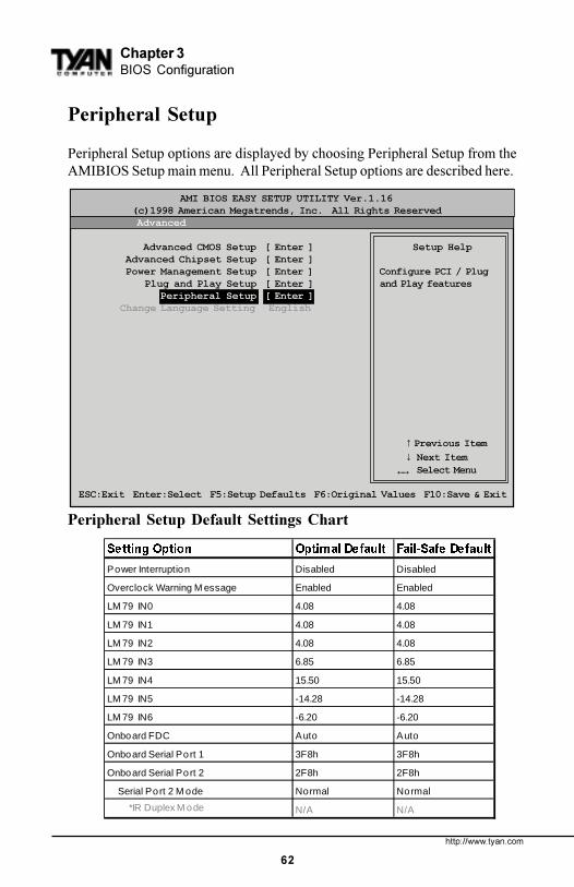
Peripheral Setup options are displayed by choosing Peripheral Setup from theAMIBIOS Setup main menu. All Peripheral Setup options are described here.
Peripheral Setup Default Settings Chart
→←
AMI BIOS EASY SETUP UTILITY Ver.1.16 (c)1998 American Megatrends, Inc. All Rights Reserved Advanced
Advanced CMOS Setup [ Enter ] Setup Help Advanced Chipset Setup [ Enter ] Power Management Setup [ Enter ] Configure PCI / Plug Plug and Play Setup [ Enter ] and Play features Peripheral Setup [ Enter ] Change Language Setting English
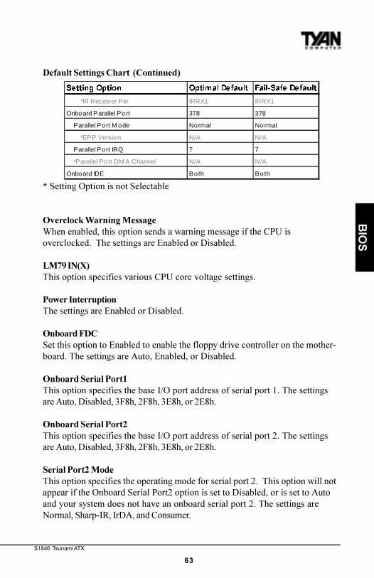
Overclock Warning MessageWhen enabled, this option sends a warning message if the CPU isoverclocked. The settings are Enabled or Disabled.
LM79 IN(X)This option specifies various CPU core voltage settings.
Power InterruptionThe settings are Enabled or Disabled.
Onboard FDC Set this option to Enabled to enable the floppy drive controller on the mother-board. The settings are Auto, Enabled, or Disabled.
Onboard Serial Port1 This option specifies the base I/O port address of serial port 1. The settingsare Auto, Disabled, 3F8h, 2F8h, 3E8h, or 2E8h.
Onboard Serial Port2 This option specifies the base I/O port address of serial port 2. The settingsare Auto, Disabled, 3F8h, 2F8h, 3E8h, or 2E8h.
Serial Port2 ModeThis option specifies the operating mode for serial port 2. This option will notappear if the Onboard Serial Port2 option is set to Disabled, or is set to Autoand your system does not have an onboard serial port 2. The settings areNormal, Sharp-IR, IrDA, and Consumer.
6HWWLQJ�2SWLRQ 2SWLPDO�'HIDXOW )DLO�6DIH�'HIDXOW
*IR Receiver P in IRRX1 IRRX1
Onboard Parallel Port 378 378
Parallel Port M ode Normal Normal
*EPP Version N/A N/A
Parallel Port IRQ 7 7
*Parallel Port DM A Channel N/A N/A
Onboard IDE Both Both
http://www.tyan.com
64
Chapter 3BIOS Configuration
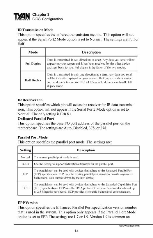
IR Transmission ModeThis option specifies the infrared transmission method. This option will notappear if the Serial Port2 Mode option is set to Normal. The settings are Full orHalf.
IR Receiver PinThis option specifies which pin will act as the receiver for IR data transmis-sion. This option will not appear if the Serial Port2 Mode option is set toNormal. The only setting is IRRX1.OnBoard Parallel Port This option specifies the base I/O port address of the parallel port on themotherboard. The settings are Auto, Disabled, 378, or 278.
Parallel Port ModeThis option specifies the parallel port mode. The settings are:
EPP VersionThis option specifies the Enhanced Parallel Port specification version numberthat is used in the system. This option only appears if the Parallel Port Modeoption is set to EPP. The settings are 1.7 or 1.9. Version 1.9 is common on
newer devices; consult your device�s user information for the appropriate porttype. There are no default settings.
Parallel Port IRQThis option specifies the IRQ used by the parallel port, and only appears ifOnBoard Parallel Port is set to 278 or 378. The settings are 5 or 7.
Parallel Port DMA ChannelThis option is only available if the setting for the Parallel Port Mode option isset to ECP and the OnBoard Parallel Port option is set to 378, 278, or 3BC. Thisoption sets the DMA channel used by the parallel port. The settings are 0through 7 in increments of one.
Onboard IDEThis option specifies the IDE channel used by the onboard IDE controller. Thesettings are Disabled, Primary, Secondary, or Both.
http://www.tyan.com
66
Chapter 3BIOS Configuration
AMI BIOS EASY SETUP UTILITY Ver.1.16 (c)1998 American Megatrends, Inc. All Rights Reserved Main Advanced Security Exit
Set Supervisor Password [ Enter ] Setup Help Set User Password [ Enter ]
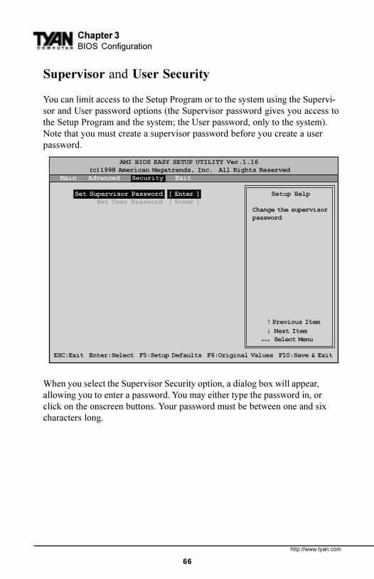
You can limit access to the Setup Program or to the system using the Supervi-sor and User password options (the Supervisor password gives you access tothe Setup Program and the system; the User password, only to the system).Note that you must create a supervisor password before you create a userpassword.
When you select the Supervisor Security option, a dialog box will appear,allowing you to enter a password. You may either type the password in, orclick on the onscreen buttons. Your password must be between one and sixcharacters long.
S1846 Tsunami ATX
67
BIO
S
Once you have entered your new password, you will be asked to confirm it. Ifthe two passwords do not match, you will be prompted to enter a new pass-word, and then to confirm it. This will continue until you enter the same seriesof characters both times. Once this is accomplished, a dialog box will appearand notify you that the Supervisor Password has been installed. You may thenselect the User Security option and enter a password for the user.You can enter a new User password at any time simply by selecting the UserSecurity option, and typing in a new password. To enter a new Supervisorpassword, select the Supervisor Security option. You will be asked to enter thecurrent password. After you do so, you will be prompted to enter the newpassword.
In either the Supervisor or User Security options, pressing <Enter> once whenasked for a new password, and a second time when asked to confirm the newpassword, will uninstall the existing password. Note that uninstalling theSupervisor password uninstalls the User password as well.
Language Utility
Currently, the BIOS Setup program is available only in English.
Flash Writer Utility
The AMI Flash Writer Utility is now included in the AMIBIOS, and so it issimpler to upgrade the BIOS of your mainboard. The system BIOS is stored ona flash EEPROM ROM chip on the mainboard which can be erased andreprogrammed by following the directions on the following page.1. From the DOS prompt, rename the BIOS file that you have downloaded to�amiboot.rom� and copy it on to a floppy disk.2. Insert the floppy disk with the BIOS upgrade into the A: drive.3. Turn the power off.4. While holding the <Ctrl> and <Home> keys, turn the power on. The systemwill begin to read from the A: drive, and write the BIOS information containedon the floppy disk in that drive to the EEPROM ROM chip. When the BIOShas been totally reprogrammed, the system will reboot with the new BIOS inoperation.5. If the system does not reboot in three minutes, power down the system waita few seconds, and then turn the power back on again. You will be prompted topress <F1> to run Setup. You may check your settings at this time, or simplysave and exit the program.
http://www.tyan.com
68
Chapter 4System Resources
chap
ter 4
System Resources
Beep Codes
Fatal errors, which halt the boot process, are communicated through a series ofaudible beeps. If AMIBIOS POST can initialize the system video display, itdisplays the error message. Displayed error messages, in most cases, allow thesystem to continue to boot. Displayed error messages are described on pages75-76. See the top of the next page for the beep code chart.
S1846 Tsunami ATX
69
SY
ST
EM
Troubleshooting System Problems
If the computer beeps... then...1, 2, or 3 times... reseat the memory SIMMs or DIPs.
If the system still beeps, replace thememory.
6 times... reseat the keyboard controller chip. Ifit still beeps, replace the keyboardcontroller. If it still beeps, try adifferent keyboard, or replace thekeyboard fuse, if there is one.
8 times... there is a memory error on the videoadapter. Replace the video adapter, orthe RAM on the video adapter.
9 times... the BIOS ROM chip is bad. Thesystem probably needs a new BIOSROM chip.
11 times... reseat the cache memory on themotherboard. If it still beeps, replacethe cache memory.
4, 5, 7, or 10 times... for 5 or 7 beeps, first test with a new CPU - if thatdoes not solve the problem, then motherboard mustbe replaced.
Bootblock Recovery CodesThe bootblock recovery checkpoint codes are listed in order of execution.
Uncompressed Initialization CodesThe following routine checkpoint codes are listed in order of execution. Thesecodes are uncompressed in F000h shadow RAM. The table begins on the nextpage.
Additional Bus CheckpointsWhile control is in the bus routines, additional checkpoints are ouput to I/Oport address 0080h as word to identify the routines being executed. These areword checkpoints. The low byte of checkpoint is the system BIOS checkpointwhere control is passed to the different bus routines. The high byte ofcheckpoint indicates that the routine is being executed in different buses.
The high byte of these checkpoints includes the following information:
stiB noitpircseD
4-7stiB
0000 .subehtnosecivedllaelbasiD.0noitcnuF
1000 .subehtnosecivedcitatsezilaitinI.1noitcnuF
0100 .subehtnosecivedtuptuoezilaitinI.2noitcnuF
1100 .subehtnosecivedtupniezilaitinI.3noitcnuF
0010 .subehtnosecivedLPIezilaitinI.4noitcnuF
1010 .subehtnosecivedlarenegetaitinI.5noitcnuF
0110 .subehtnognitroperrorreezilaitinI.6noitcnuF
1110 .sesubllarofsMORno-ddaezilaitinI.7noitcnuF
0-3stiB subehtyficepS
0 .reganaMnoitazilaitinIeciveDMIDcireneG
1 .secivedmetsySdraobnO
2 .secivedASI
3 .secivedASIE
4 .secivedPnPASI
5 .secivedICP
Chapter 4System Resources
S1846 Tsunami ATX
77
SY
ST
EM
Displayed Error Messages
If an error occurs after the system display has been initialized, the errormessage will be displayed as follows:
ERROR Message Line 1ERROR Message Line 2Press <F1> to continue
and the system will halt. The system will not halt if the Wait for <F1> If AnyError option in Advanced Setup is Disabled.
RUN SETUP UTILITY
may also appear. Press <F1> to run WINBIOS Setup if this message appears.
Tyan offers two different options for securing Intel�s Pentium II CPUs onto themotherboard. Each option provides retention for both older Pentium II�s aswell as newer Pentium II�s (including Celeron).
OPTION 1:Two different types of retention modules are included in the motherboardpackage. For older versions of Pentium II, use the retention module shown inFigure 1. For newer versions of Pentium II CPUs (including Celeron), use theretention module shown in Figure 2. (Screws for the retention modules areprovided.)
Figure 1 Figure 2
Appendix 1CPU Retention Module Options
S1846 Tsunami ATX
81
OPTION 2:One universal retention module is included in the motheboard package. Thistype of retention module adapts to both old and new Pentium II CPUs - seeFigure 3. (Screws for the retention modules are provided)
Figure 3
http://www.tyan.com
82
ACPI (Advanced Configuration and Power Interface) is a power managementspecification that allows the operating system to control the amount of powerdistributed to the computer�s devices. Devices not in use can be turned off,reducing unnecessary power expenditure.
AGP (Accelerated Graphics Port) is a PCI-based interface which wasdesigned specifically for demands of 3D graphics applications. The 32-bitAGP channel directly links the graphics controller to the main memory.While the channel runs at only 66MHz, it supports data transmission duringboth the rising and falling ends of the clock cycle, yielding an effective speedof 133MHz.
AT was the original form factor of IBM�s PC.
ATAPI (AT Attachment Packet Interface), also known as IDE or ATA, is adrive implementation that includes the disk controller on the device itself. Itallows CD-ROMs and tape drives to be configured as master or slave devices,just like hard drives.
ATX form factor was designed to replace the AT form factor. It improves onthe AT design by rotating the board ninety degrees, so that the IDE connec-tors are closer to the drive bays, and the CPU is closer to the power supply
Ap
pen
dix
2
Glossary
Appendix 2Glossary
S1846 Tsunami ATX
83
and cooling fan. The keyboard, mouse, serial, USB, and parallel ports are builtin.
Bandwidth refers to carrying capacity. The greater the bandwidth, the moredata the bus, phone line, or other electrical path, can carry. Greater bandwidth,then, also results in greater speed.
A BBS (Bulletin Board System) is a computer system with a number ofmodems hooked up to it which acts as a center for users to post messages andaccess information.
The BIOS (Basic Input/Output System) program resides in the ROM chip,and provides the basic instructions for controlling your computer�s hardware.Both the operating system and application software use BIOS routines toensure compatibility.
A buffer is a portion of RAM which is used to temporarily store data, usuallyfrom an application, though it is also used when printing, and in most key-board drivers. The CPU can manipulate data in a buffer before copying it, all atonce, to a disk drive. While this improves system performance--reading to orwriting from a disk drive a single time is much faster than doing so repeatedly--there is the possibility of losing your data should the system crash. Informa-tion stored in a buffer is temporarily stored, not permanently saved.
A bus is a data pathway. The term is used especially to refer to the connec-tion between the processor and system memory, and between the processorand PCI or ISA local buses.
Bus mastering allows peripheral devices and IDEs to access the systemmemory without going through the CPU (similar to DMA channels).
A cache is a temporary storage area for data that will be needed often by anapplication. Using a cache lowers data access times, since the neededinformation is stored in the SRAM instead of in the slower DRAM. Note thatthe cache is also much smaller than your regular memory: a typical cache sizeis 512KB, while you may have as much as 1GB of regular memory.
Cache size refers to the physical size of the cache onboard. This should notbe confused with the cacheable area, which is the total amount of memory
GL
OS
SA
RY
http://www.tyan.com
84
which can be scanned by the system in search of data to put into the cache. Atypical setup would be a cache size of 512KB, and a cacheable area of 512MB.In this case, up to 512MB of the main memory onboard is capable of beingcached. However, only 512KB of this memory will be in the cache at any givenmoment. Any main memory above 512MB could never be cached.
Closed and open jumpers Jumpers and jumper pins are active when theyare On or Closed, and inactive when they are Off or Open.
CMOS Complementary Metal-Oxide Semiconductors are chips that hold thebasic start-up information for the BIOS.
The COM port is another name for the serial port, which is so-calledbecause it transmits the eight bits of a byte of data along one wire, andreceives data on another single wire (that is, the data is transmitted in serialform, one bit after another). Parallel ports transmit the bits of a byte on eightdifferent wires at the same time (that is, in parallel form, eight bits at the sametime).
DIMM Dual In-line Memory Modules are a faster and more capacious formof RAM than SIMMs, and do not need to be installed in pairs.
DIMM bank DIMM banks are sometimes called DIMM sockets, becausethe physical slot and the logical unit are the same. That is, one DIMMmodule fits into one DIMM socket, which is capable of acting as a memorybank.
DMA Direct Memory Access channels are similar to IRQs. DMA channelsallow hardware devices (like sound cards or keyboards) to access the mainmemory without involving the CPU. This frees up CPU resources for othertasks. As with IRQs, it is vital that you do not double up devices on a singleline. Plug and Play devices will take care of this for you.
In Doze mode, only the CPU�s speed is slowed.
DRAM Dynamic RAM is a widely available, very affordable form of RAMwhich has the unfortunate tendency to lose data if it is not recharged regu-larly (every few milliseconds). This refresh requirement makes DRAM three toten times slower than non-recharged RAM such as SRAM.
Appendix 2Glossary
S1846 Tsunami ATX
85
EDO RAM (Extended Data-Out RAM) speeds access to memory locationsby assuming that memory addresses are static: the next time it looks for a bit ofdata, it will be at the same spot, or one nearby.
EEPROM Electrically Erasable Programmable ROM, also called Flash BIOS,is a ROM chip which can, unlike normal ROM, be updated. This allows you tokeep up with changes in the BIOS programs without having to buy a new chip.TYAN�s BIOS updates can be found at http://www.tyan.com/html/drivers.html
ESCD (Extended System Configuration Data) is a format for storing informa-tion about Plug and Play devices in the system BIOS. This information helpsproperly configure the system each time it boots.
Firmware is low level software that controls the system hardware.
Form factor is an industry term for the size, shape, power supply type,and external connector type of the PCB (personal computer board) ormotherboard. The standard form factors are the AT and ATX, althoughTYAN also makes some Baby-AT boards.
A Global timer is an onboard hardware timer, such as the Real TimeClock.
Handshaking is a form of encryption. One system, typically the server,sends an encryption scheme to another agent, typically a client. Thus, theclient�s data is protected during transmittal to the server.
HDD stands for Hard Disk Drive.
H-SYNC controls the horizontal properties of the monitor.
IC (Integrated Circuit) is the formal name for the computer chip.
IDE Integrated Device (or Drive) Electronics is a simple, self-containedhard drive interface. It can handle drives up to 8.4GB in size. Almost allIDEs sold now are in fact Enhanced IDEs (EIDEs).
GL
OS
SA
RY
http://www.tyan.com
86
IDE INT (IDE Interrupt) is a hardware interrupt signal that goes to the IDE.
I/O Input/Output is the connection between your computer and another pieceof hardware (mouse, keyboard, etc.).
IRQ An Interrupt Request is an electronic request that runs from a hardwaredevice to the CPU. The interrupt controller assigns priorities to incomingrequests and delivers them to the CPU. It is important that there is only onedevice hooked up to each IRQ line; doubling up devices on IRQ lines can lockup your system. Happily, Plug and Play operating systems take care of thesedetails for you.
ISA stands for Industry Standard Architecture. ISA is a slower 8- or 16-bitBUS (data pathway).
Latency is the amount of time that one part of a system spends waiting foranother part to catch up. This is most common when the system sends dataout to a peripheral device, and is waiting for the peripheral to send some databack (peripherals tend to be slower than onboard system components).
NVRAM ROM and EEPROM are both examples of Non-Volatile RAM,memory that holds its data without power. DRAM, in contrast, is volatile.
OEMs (Original Equipment Manufacturers) like Compaq or IBM packageother companies� motherboards and hardware inside their case and sell them.
The parallel port transmits the bits of a byte on eight different wires at the
same time (that is, in parallel form, eight bits at the same time).
PCI stands for Peripheral Component Interconnect. PCI is a 32-bit local bus(data pathway) which is faster than the ISA bus. Local buses are those whichoperate within a single system (as opposed to a network bus, which connectsmultiple systems).
The PCI PIO (PCI Programmable Input/Output) modes are the datatransfer modes used by IDE drives. These modes use the CPU for datatransfer (DMA channels do not). PCI refers to the type of bus used by thesemodes to communicate with the CPU.
Appendix 2Glossary
S1846 Tsunami ATX
87
PCI-to-PCI bridge allows you to connect multiple PCI devices onto one
PCI slot.
Pipeline burst SRAM is a fast secondary cache. It is used as a secondarycache because SRAM is slower than SDRAM, but usually larger. Data iscached first to the faster primary cache, and then, when the primary cache isfull, to the slower secondary cache.
Pipelining improves system performance by allowing the CPU to beginexecuting a second instruction before the first is completed. A pipeline can belikened to an assembly line, with a given part of the pipeline repeatedlyexecuting a set part of an operation on a series of instructions.
PM timers (Power Management timers) are software timers that countdown the number of seconds or minutes until the system times out and enterssleep, suspend, or doze mode.
PnP is an acronym for Plug and Play, a design standard that has becomeascendant in the industry. Plug and Play devices require little set-up to use.Novice end users can simply plug them into a computer that is running on aPlug and Play-aware operating system (such as Windows 95), and go towork. Devices and operating systems that are not Plug and Play require youto reconfigure your system each time you add or change any part of yourhardware.
The term RAM (Random Access Memory), while technically referring to atype of memory where any byte can be accessed without touching theadjacent data, is often used to refer to the system�s main memory. Thismemory is available to any program running on the computer.
ROM (Read-Only Memory) is a storage chip which contains the BIOS(Basic Input/Output System), the basic instructions required to boot thecomputer and start up the operating system.
SDRAM (Synchronous Dynamic RAM) is so-called because it can keeptwo sets of memory addresses open simultaneously. By transferring dataalternately from one set of addresses, and then the other, SDRAM cuts downon the delays associated with non-synchronous RAM, which must close oneaddress bank before opening the next.
GL
OS
SA
RY
http://www.tyan.com
88
The serial port is so called because it transmits the eight bits of a byte ofdata along one wire, and receives data on another single wire (that is, thedata is transmitted in serial form, one bit after another).
SIMM Single In-line Memory Modules are the most common form ofRAM. They must be installed in pairs, and do not have the carrying capacityor the speed of DIMMs.
SIMM bank/socket SIMM sockets are the physical slots into which youstick SIMM modules. A pair of SIMM sockets form a SIMM bank, and act as aunit. If only one socket is filled, the bank will not operate.
In Sleep/Suspend mode, all devices except the CPU shut down.
SRAM Static RAM, unlike DRAM, does not need to be refreshed in orderto prevent data loss. Thus, it is faster, and more expensive.
In Standby mode, the video and fixed disk drive shut down; all otherdevices operate normally.
UltraDMA/33 is a fast version of the old DMA channel. UltraDMA isalso called UltraATA. Without UltraDMA your system cannot take advantageof the higher data transmission rates of the new UltraATA hard drives.
Universal Serial Bus or USB, is a versatile port. This one port type canfunction as a serial, parallel, mouse, keyboard, or joystick port. It is fastenough to support video transfer, and is capable of supporting up to 127daisy-chained peripheral devices.
VGA (Video Graphics Array) is the PC video display standard.
V-SYNC controls the vertical properties of the monitor.
ZIF socket Zero Insertion Force sockets make it possible to insert CPUswithout damaging the sensitive pins. The CPU is lightly placed in an openZIF socket, and the metal lever pulled down. This shifts the processor overand down, guiding it into place on the board.
Appendix 2Glossary
S1846 Tsunami ATX
89
Notice for the USACompliance Information Statement (Declaration of Conformity Procedure) DoCFCC Part 15: This Device complies with Part 15 of the FCC Rules.Operation is subject to the following conditions:1) this device may not cause harmful interference, and2) this device must accept any interference received including interference thatmay cause undesired operation. If this equipment does cause harmful interfer-ence to radio or television reception, which can be determined by turning theequipment off and on, the user is encouraged to try one or more of thefollowing measures:
• Reorient or relocate the receiving antenna.• Increase the separation between the equipment and receiver.• Plug the equipment into an outlet on a circuit different from
that of the receiver.• Consult the dealer or an experienced radio/television
technician for help.
Notice for CanadaThis apparatus complies with the Class B limits for radio interference asspecified in the Canadian Department of Communications Radio InterferenceRegulations. (Cet appareil est conforme aux normes de Classe B d� interfer-ence radio tel que spécifié par le Ministére Canadien des Communicationsdans les réglements d�interférence radio.)
Notice for Europe (CE Mark)This product is in conformity with the Council Directive 89/336/EEC, 92/31/EEC(EMC).
CAUTION: Lithium Batteries included with this board. Danger of explosion ifbattery is incorrectly replaced. Replace only with the same or equivalent typerecommended by manufacturer. Dispose of used batteries according tomanufacturer instructions. F1 (Fuse 1), F2 (Fuse 2): Rated 30V DC, hold currentat 1.6 A.
Note: The joystick port maximum output rating is 9 amperes at 5 volts.