FFC ( Flat Flexible Cable ) Connectors Features and Benefits Applications The TE Connectivity (TE) family of flat flexible cable connectors includes a wide variety of high density cable-to-board and cable-to-cable connectors designed for automated assembly. The family is composed of pin and receptacle housings on .100 [2.54] centerline contact spacing and receptacle housings on .050 [1.27] centerline contact spacing. Receptacle housings not only mate with the pin housings, but also mate with an array of printed circuit board headers from other TE connector lines, including AMPMODU connectors. The FFC Family also includes the higher performance FLEXPAC connector system; the specialized TRIO-MATE connector system, and a ZIF [zero insertion force] connector family. te.com/products/FFC AVAILABLE IN 0.050 AND 0.100 CENTERLINE SPACING SPECIALIZED CONTACT DESIGN FOR MAXIMUM PERFORMANCE WIDE RANGE OF STANDARD OPTIONS AND FEATURES WORLD CLASS APPLICATION TOOLING 0.050 and 0.100 hard English centerlines TRIO-MATE for high retention force LIF applications ZIF options for higher mating cycles. Single and dual row options available Latching and polarizing options available Terminates FFC and FEC cable. PCs – Desktop and Laptop Printers Camera Membrane Switches Disk Drives Data Systems Business Equipment Industrial Controls Appliance
Transcript
FFC (Flat Flexible Cable) Connectors
Features and Benefits
Applications
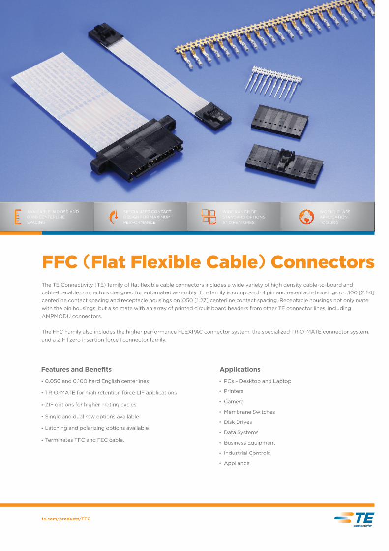
The TE Connectivity (TE) family of flat flexible cable connectors includes a wide variety of high density cable-to-board and cable-to-cable connectors designed for automated assembly. The family is composed of pin and receptacle housings on .100 [2.54] centerline contact spacing and receptacle housings on .050 [1.27] centerline contact spacing. Receptacle housings not only mate with the pin housings, but also mate with an array of printed circuit board headers from other TE connector lines, including AMPMODU connectors.
The FFC Family also includes the higher performance FLEXPAC connector system; the specialized TRIO-MATE connector system, and a ZIF [zero insertion force] connector family.
te.com/products/FFC
AVAILABLE IN 0.050 AND 0.100 CENTERLINE SPACING
SPECIALIZED CONTACT DESIGN FOR MAXIMUM PERFORMANCE
WIDE RANGE OF STANDARD OPTIONS AND FEATURES
WORLD CLASS APPLICATION TOOLING
0.050 and 0.100 hard English centerlines
TRIO-MATE for high retention force LIF applications
ZIF options for higher mating cycles.
Single and dual row options available
Latching and polarizing options available
Terminates FFC and FEC cable.
PCs – Desktop and Laptop
Printers
Camera
Membrane Switches
Disk Drives
Data Systems
Business Equipment
Industrial Controls
Appliance
CONTACTS
TE’ s FFC contacts are arguably the most important components of an FFC connection. TE’ s contact design is a competitive di�erentiator, and is well proven within the industry.
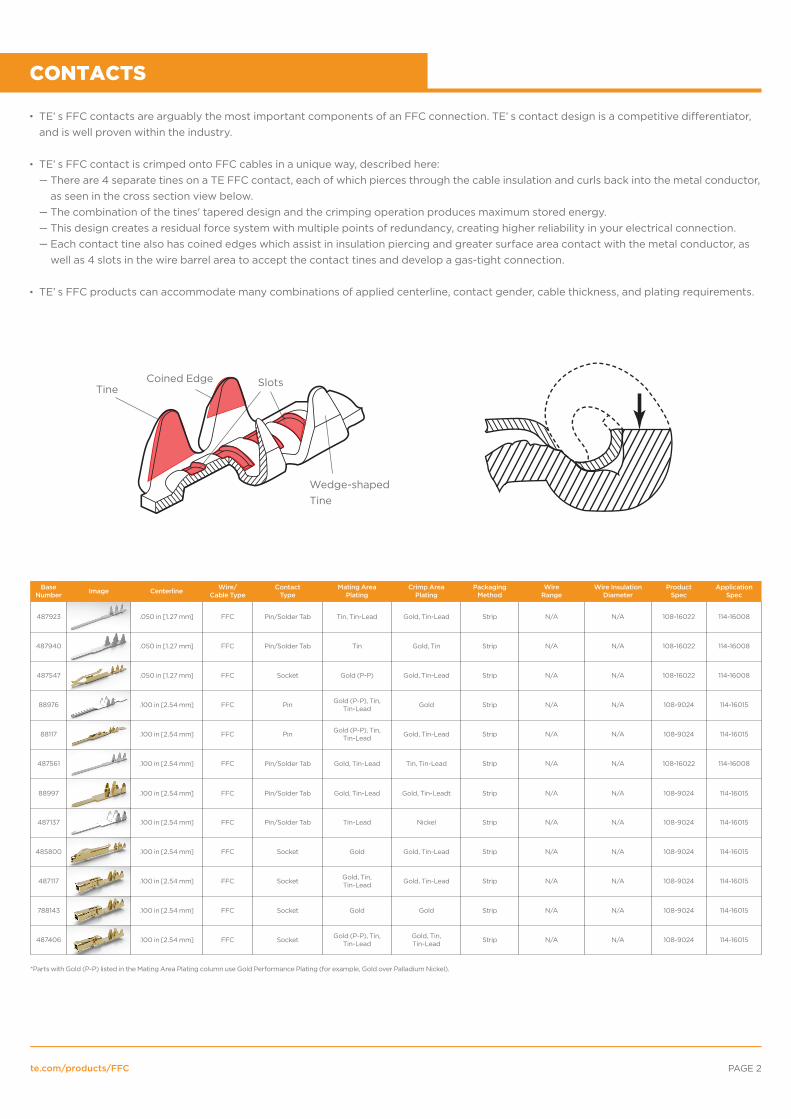
TE’ s FFC contact is crimped onto FFC cables in a unique way, described here:
TE’ s FFC products can accommodate many combinations of applied centerline, contact gender, cable thickness, and plating requirements.
te.com/products/FFC PAGE 2
.050 in [1.27 mm]
.050 in [1.27 mm]
.050 in [1.27 mm]
.100 in [2.54 mm]
.100 in [2.54 mm]
.100 in [2.54 mm]
.100 in [2.54 mm]
.100 in [2.54 mm]
.100 in [2.54 mm]
.100 in [2.54 mm]
.100 in [2.54 mm]
.100 in [2.54 mm]
FFC
FFC
FFC
FFC
FFC
FFC
FFC
FFC
FFC
FFC
FFC
FFC
Pin/Solder Tab
Pin/Solder Tab
Pin/Solder Tab
Pin/Solder Tab
Pin/Solder Tab
Socket
Pin
Pin
Socket
Socket
Socket
Socket
Tin, Tin-Lead
Tin
Gold (P-P)
Gold (P-P), Tin,Tin-Lead
Gold (P-P), Tin,Tin-Lead
Gold, Tin-Lead
Gold, Tin-Lead
Tin-Lead
Gold
Gold
Gold, Tin,Tin-Lead
Gold (P-P), Tin,Tin-Lead
Gold, Tin-Lead
Gold, Tin
Gold, Tin-Lead
Gold
Gold, Tin-Lead
Tin, Tin-Lead
Gold, Tin-Leadt
Nickel
Gold, Tin-Lead
Gold, Tin-Lead
Gold
Gold, Tin,Tin-Lead
Strip
Strip
Strip
Strip
Strip
Strip
Strip
Strip
Strip
Strip
Strip
Strip
108-16022
108-16022
108-16022
108-9024
108-9024
108-16022
108-9024
108-9024
108-9024
108-9024
108-9024
108-9024
114-16008
114-16008
114-16008
114-16015
114-16015
114-16008
114-16015
114-16015
114-16015
114-16015
114-16015
114-16015
N/A
N/A
N/A
N/A
N/A
N/A
N/A
N/A
N/A
N/A
N/A
N/A
N/A
N/A
N/A
N/A
N/A
N/A
N/A
N/A
N/A
N/A
N/A
N/A
487923
487940
487547
88976
88117
487561
88997
788143
487406
485800
487117
487137
Centerline Wire/Cable Type
ContactType
Mating AreaPlating
Crimp AreaPlating
PackagingMethod
ProductSpec
ApplicationSpec
Wire InsulationDiameter
WireRangeImageBase
Number
Wedge-shapedTine
SlotsCoined EdgeTine
There are 4 separate tines on a TE FFC contact, each of which pierces through the cable insulation and curls back into the metal conductor, as seen in the cross section view below. The combination of the tines' tapered design and the crimping operation produces maximum stored energy. This design creates a residual force system with multiple points of redundancy, creating higher reliability in your electrical connection. Each contact tine also has coined edges which assist in insulation piercing and greater surface area contact with the metal conductor, as well as 4 slots in the wire barrel area to accept the contact tines and develop a gas-tight connection.
—
———
*Parts with Gold (P-P) listed in the Mating Area Plating column use Gold Performance Plating (for example, Gold over Palladium Nickel).
te.com/products/FFC PAGE 3
.100 in [2.54 mm]
.100 in [2.54 mm]
.100 in [2.54 mm]
.100 in [2.54 mm]
.100 in [2.54 mm]
.100 in [2.54 mm]
.100 in [2.54 mm]
.100 in [2.54 mm]
.100 in [2.54 mm]
.100 in [2.54 mm]
.100 in [2.54 mm]
.100 in [2.54 mm]
Round Wire
Round Wire
Round Wire
Round Wire
Round Wire
Round Wire
Round Wire
Round Wire
Round Wire
Round Wire
Round Wire
Round Wire
Pin
Pin
Pin
Pin
Pin
Pin
Pin
Gold Tin Loose Piece 108-9024 114-16015
114-16015
114-16015
114-16015
114-16015
114-16015
114-16015
114-16015
114-16015
114-16015
114-16015
114-16015
.040 - .056 in [1.02 - 1.42 mm]
0.20-0.402 mm [24-22 AWG]
0.20-0.402 mm [24-22 AWG]
0.20-0.402 mm [24-22 AWG]
494034
Centerline Wire/Cable Type
ContactType
Mating AreaPlating
Crimp AreaPlating
PackagingMethod
ProductSpec
ApplicationSpec
Wire InsulationDiameter
WireRangeImageBase
Number
494033
86658
88048
86656
86561
86557
86566
86571
86657
88017
86655
Socket
Socket
Socket
Socket
Socket
Gold
Gold (P-P)
Gold (P-P)
Gold (P-P)
Gold, Tin,Tin-Lead
Gold, Tin, Tin-Lead
Gold, Gold (P-P),Tin, Tin-Lead
Gold (P-P)
Gold (P-P)
Gold (P-P)
Gold (P-P)
Tin, Tin-Lead
Gold
Gold
Gold
Gold, Tin, Tin-Lead
Gold, Tin, Tin-Lead
Gold, Tin, Tin-Lead
Gold, Tin
Gold
Gold
Gold
Strip
Loose Piece
Loose Piece
Loose Piece
Loose Piece
Strip
Strip
Strip
Strip
Strip
Strip
0.03-0.152 mm[32-26 AWG]
0.20-0.402 mm[24-22 AWG]
0.12-0.402 mm[26-22 AWG]
0.12-0.402 mm[26-22 AWG]
0.12-0.402 mm[26-22 AWG]
0.12-0.402 mm[26-22 AWG]
0.20-0.402 mm[24-22 AWG]
0.03-0.152 mm[32-26 AWG]
0.20-0.402 mm[24-22 AWG]
.040 - .056 in[1.02 - 1.42 mm]
.040 - .056 in[1.02 - 1.42 mm]
.025 - .048 in[.64 - 1.22 mm]
.040 - .056 in[1.02 - 1.42 mm]
.040 - .056 in[1.02 - 1.42 mm]
.040 - .056 in[1.02 - 1.42 mm]
.040 - .056 in[1.02 - 1.42 mm]
.040 - .056 in[1.02 - 1.42 mm]
.040 - .056 in[1.02 - 1.42 mm]
.025 - .048 in[.64 - 1.22 mm]
.040 - .056 in[1.02 - 1.42 mm]
108-9024
108-9024
108-9024
108-9024
108-9024
108-9024
108-9024
108-9024
108-9024
108-9024
108-9024
.100 in [2.54 mm]
.100 in [2.54 mm]
.050 in [1.27 mm]
FFC and Round Wire
FFC and Round Wire
FFC and Round Wire
FFC to Round Wire
FFC to Round Wire
FFC to Round Wire
Gold Tin Strip
Strip
108-9024 114-16015
114-16015
114-16008
.035 - .060 in[.89 - 1.52 mm]
0.12-0.402 mm[26-22 AWG]
0.12-0.402 mm[26-22 AWG]
N/A N/A
86773
Centerline Wire/Cable Type
ContactType
Mating AreaPlating
Crimp AreaPlating
PackagingMethod
ProductSpec
ApplicationSpec
Wire InsulationDiameter
WireRangeImageBase
Number
86774
487941
Gold
Tin-Lead
Gold Loose Piece
Gold, Tin-Lead
.035 - .060 in[.89 - 1.52 mm] 108-9024
108-16022
The second step in creating a multi-piece FFC connection is the cable side housing.
The cable with contacts applied is loaded directly into this cable side housing to create a complete FFC Cable assembly.
Standard FFC housings are loaded with the prepared FFC cable assembly before it is mated with a board side header (in wire-to-board solutions), or another FFC cable assembly (in wire-to-wire solutions).
Housings are available in:— Standard or slimline (for low profile applications), — Single or dual row style (for increased density), — With or without latching (for increased retention), — With or without mounting ears (mounting ears provide increased cable or PCB retention).
Note that in some cases, certain housing-header combinations will not be compatible with all contacts. To confirm compatibility of housing-header-contact combinations, please contact your local TE sales representative.
HOUSINGS
*Parts with Gold (P-P) listed in the Mating Area Plating column use Gold Performance Plating (for example, Gold over Palladium Nickel).
*This row indicates the headers with which the housings are able to mate**This row indicates the contacts which may be used by each housing base number
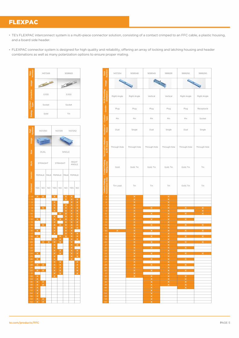
TE’s FLEXPAC interconnect system is a multi-piece connector solution, consisting of a contact crimped to an FFC cable, a plastic housing, and a board side header.
FLEXPAC connector system is designed for high quality and reliability, o�ering an array of locking and latching housing and header combinations as well as many polarization options to ensure proper mating.
Right Angle Right Angle Right Angle Right AngleVertical Vertical
Plug Plug Plug Plug Plug Receptacle
Dual
Pin Pin Pin Pin Pin Socket
Single Dual Single Dual Single
Through Hole Through Hole Through Hole Through Hole Through Hole Through Hole
Gold Gold, Tin Gold, Tin Gold, Tin Gold, Tin Tin
Tin-Lead Tin Tin Tin TinGold, Tin
1437250 1437251 1437252
DUAL SINGLE
STRAIGHT STRAIGHT
FEMALE
YES YESNO NO NO NO NOYES
MALE FEMALE FEMALEMALE
1437249 1658665
0.100 0.100
Socket Socket
Gold Tin
RIGHTANGLE
TRIO-MATE
te.com/products/FFC PAGE 6P
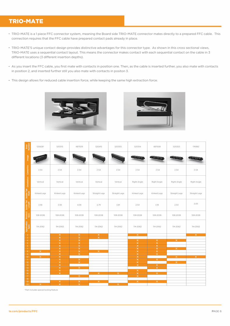
TRIO-MATE is a 1 piece FFC connector system, meaning the Board side TRIO-MATE connector mates directly to a prepared FFC cable. This connection requires that the FFC cable have prepared contact pads already in place.
TRIO-MATE’S unique contact design provides distinctive advantages for this connector type. As shown in this cross sectional views, TRIO-MATE uses a sequential contact layout. This means the connector makes contact with each sequential contact on the cable in 3 di�erent locations (3 di�erent insertion depths).
As you insert the FFC cable, you first mate with contacts in position one. Then, as the cable is inserted further, you also mate with contacts in position 2, and inserted further still you also mate with contacts in positon 3.
This design allows for reduced cable insertion force, while keeping the same high extraction force.
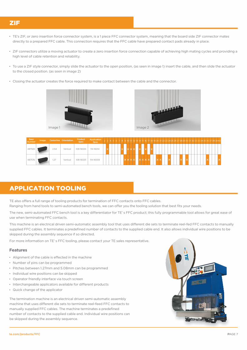
TE’s ZIF, or zero insertion force connector system, is a 1 piece FFC connector system, meaning that the board side ZIF connector mates directly to a prepared FFC cable. This connection requires that the FFC cable have prepared contact pads already in place.
ZIF connectors utilize a moving actuator to create a zero insertion force connection capable of achieving high mating cycles and providing a high level of cable retention and reliability.
To use a ZIF style connector, simply slide the actuator to the open position, (as seen in image 1) insert the cable, and then slide the actuator to the closed position. (as seen in image 2)
Closing the actuator creates the force required to make contact between the cable and the connector.
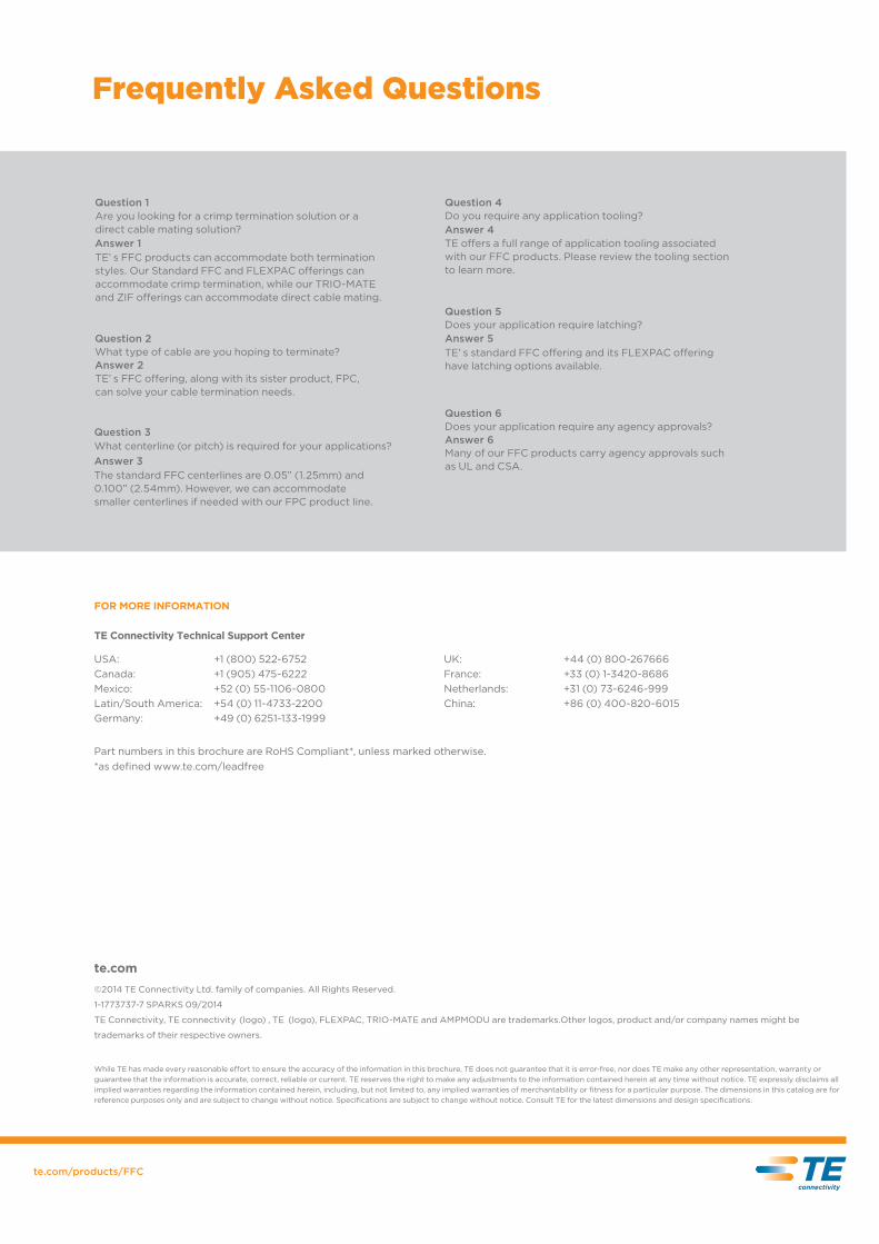
TE also o�ers a full range of tooling products for termination of FFC contacts onto FFC cables. Ranging from hand tools to semi-automated bench tools, we can o�er you the tooling solution that best fits your needs.
The new, semi-automated FFC bench tool is a key di�erentiator for TE’ s FFC product; this fully programmable tool allows for great ease of use when terminating FFC contacts.
This machine is an electrical driven semi-automatic assembly tool that uses di�erent die sets to terminate reel-fed FFC contacts to manually supplied FFC cables. It terminates a predefined number of contacts to the supplied cable end. It also allows individual wire positions to be skipped during the assembly sequence if so directed.
For more information on TE’ s FFC tooling, please contact your TE sales representative.
ZIF
APPLICATION TOOLING
Features
te.com/products/FFC PAGE 7P
Alignment of the cable is e�ected in the machine
Number of pins can be programmed
Pitches between 1.27mm and 5.08mm can be programmed
Individual wire positions can be skipped
Operator friendly interface via touch screen
Interchangeable applicators available for di�erent products
Quick change of the applicator
The termination machine is an electrical driven semi-automatic assembly machine that uses di�erent die sets to terminate reel-feed FFC contacts to manually supplied FFC cables. The machine terminates a predefined number of contacts to the supplied cable end. Individual wire positions can be skipped during the assembly sequence.
Question 4Do you require any application tooling?Answer 4TE o�ers a full range of application tooling associated with our FFC products. Please review the tooling section to learn more.
Question 1
Answer 1TE’ s FFC products can accommodate both termination styles. Our Standard FFC and FLEXPAC o�erings can accommodate crimp termination, while our TRIO-MATE and ZIF o�erings can accommodate direct cable mating.
Are you looking for a crimp termination solution or a direct cable mating solution?
Question 2What type of cable are you hoping to terminate?Answer 2TE’ s FFC o�ering, along with its sister product, FPC, can solve your cable termination needs.
Question 5Does your application require latching?Answer 5TE’ s standard FFC o�ering and its FLEXPAC o�ering have latching options available.
Question 6Does your application require any agency approvals?Answer 6Many of our FFC products carry agency approvals such as UL and CSA.
Question 3What centerline (or pitch) is required for your applications?Answer 3The standard FFC centerlines are 0.05” (1.25mm) and 0.100” (2.54mm). However, we can accommodate smaller centerlines if needed with our FPC product line.
TE Connectivity, TE connectivity (logo) , TE (logo), FLEXPAC, TRIO-MATE and AMPMODU are trademarks.Other logos, product and/or company names might be
trademarks of their respective owners.
While TE has made every reasonable e�ort to ensure the accuracy of the information in this brochure, TE does not guarantee that it is error-free, nor does TE make any other representation, warranty or guarantee that the information is accurate, correct, reliable or current. TE reserves the right to make any adjustments to the information contained herein at any time without notice. TE expressly disclaims all implied warranties regarding the information contained herein, including, but not limited to, any implied warranties of merchantability or fitness for a particular purpose. The dimensions in this catalog are for reference purposes only and are subject to change without notice. Specifications are subject to change without notice. Consult TE for the latest dimensions and design specifications.