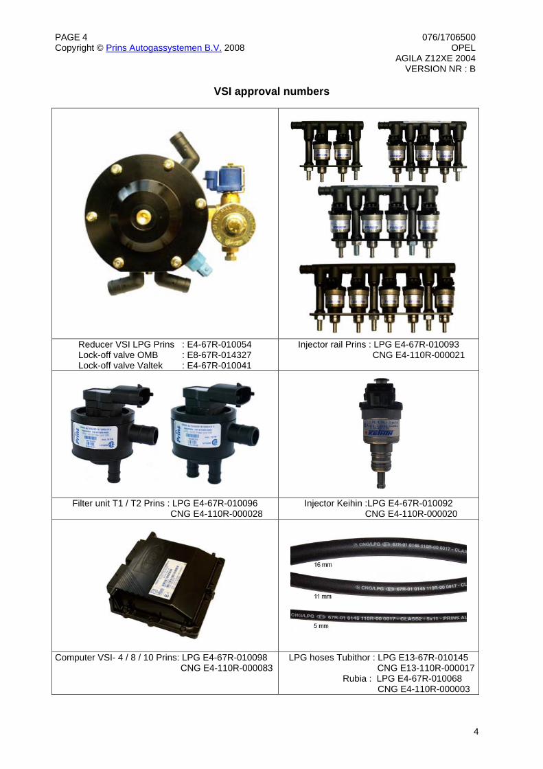
MAKE OF AUTOMOBILE: OPELTYPE: AGILAPISTON DISPLACEMENT: 1200NUMBER OF VALVES: 16ENGINE NUMBER: Z12XETRANSMISSION TYPE ( MT / AT ) MTVEHICLE CATEGORIES M or N MTYPE VSI INJECTOR ( NUMBER + COLOR ) 180/30410 WHITEVERSION ( LPG / CNG ) LPGINJECTION SYSTEM: MPIMODEL YEAR: 2004SYSTEM APPROVAL NUMBER ( R115 ) R115-000031LOCATION SYSTEM STICKER right side, centre door postENGINE SET NUMBER 357/0220000
Required equipment / tools / materials for installing a complete system
- Complete workshop toolbox ( wrenches, screwdrivers, cutters, pliers, ratchet, sockets ) - Car lift - Portable computer : operating on Windows 98,W2000 or XP.
Internal memory : 16 Mb or more Memory HD space : 5MB Screen : 256 colours, advise colours 16 bits or more Com port : 1 free COM port 1 or COM port 2 with a 9 or 25 pins connector
- Vehicle fuel system scan tool or OBD scan tool Prins ( part nr. 099/99928 ) - Exhaust gas analyser - Multimeter - Oscilloscope - Prins VSI diagnostic software - Prins VSI serial interface - Prins VSI break out box ( part nr. 080/70090 ) - Torque wrench ( 10Nm ) - Portable light - Assortment drill bits 4 to 12 mm - Assortment cutters ( ø 20, 30, 50, 70 mm ) - Punching tool ø 70 mm - Round file - Portable drill or pneumatic drill - Threading device ( male M6x1, M8x1, M10x1 ) - Pipe-flaring tool ( for 6 and 8 mm copper pipe ) - Air gun - Vacuum cleaner - Hot air gun - Allan spanner for inlet couplings 3,5mm ( part nr. 099//9970 ) - Reducer adjustment tool ( part nr. 099/9960 ) - Molex extraction tool for VSI switch connector ( part nr. 090/9929 ) - Soldering iron, soldering tin - Wire-stripping pliers - Adhesive tape - Adhesive sealant - Thread locking compound - Anti-corrosion agent / black body coating - Gas leak detection device or foam leak spray - Shrink sleeves - Engine coolant
Vehicle check
- Check the vehicle drivability on petrol - Check the fuel system for error codes ( scan tool ) - Check if the catalytic converter is in good condition ( exhaust gas analyzer ) - Check the condition of the ignition system ( spark plugs, cables, coil )
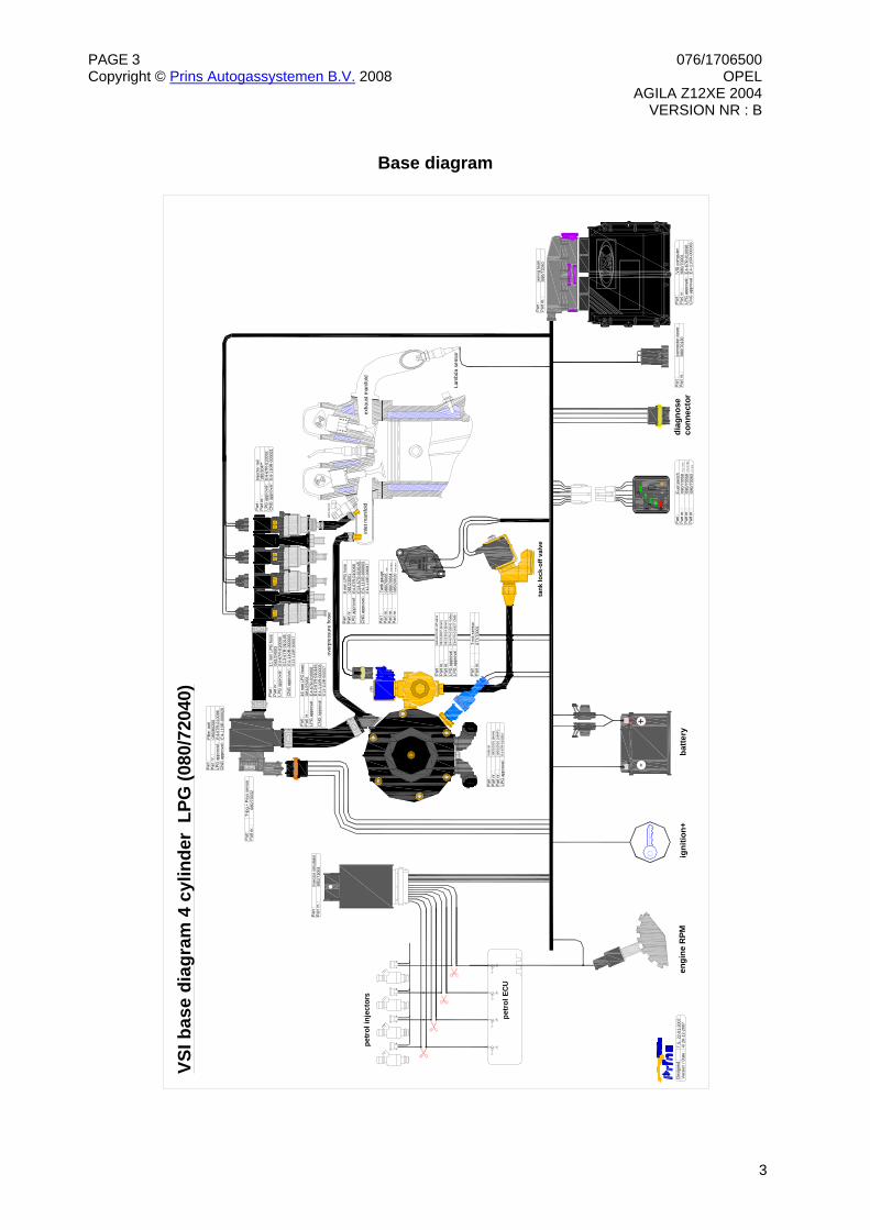
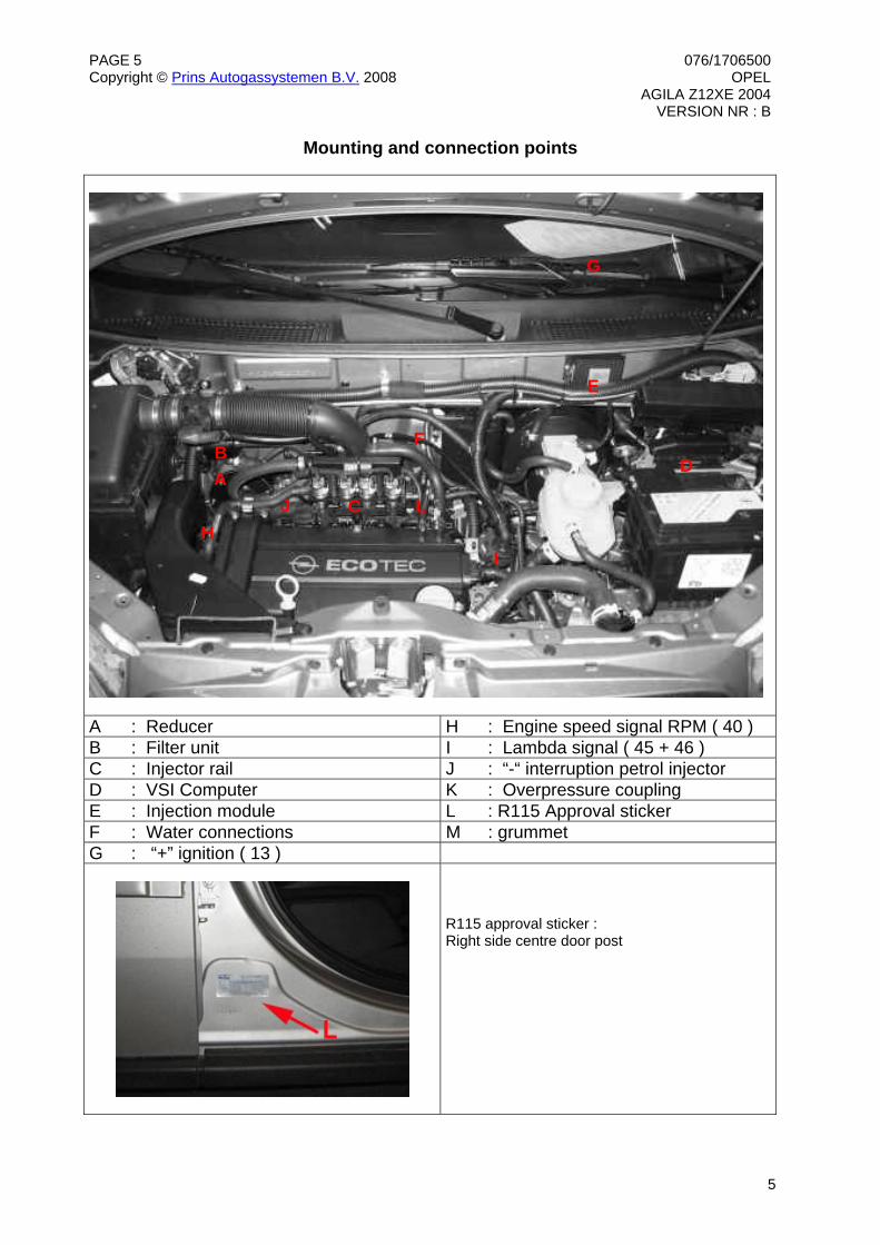
A : Reducer H : Engine speed signal RPM ( 40 ) B : Filter unit I : Lambda signal ( 45 + 46 ) C : Injector rail J : “-“ interruption petrol injector D : VSI Computer K : Overpressure coupling E : Injection module L : R115 Approval sticker F : Water connections M : grummet G : “+” ignition ( 13 )
R115 approval sticker : Right side centre door post
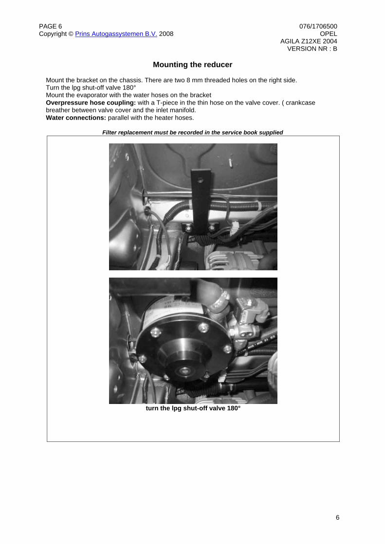
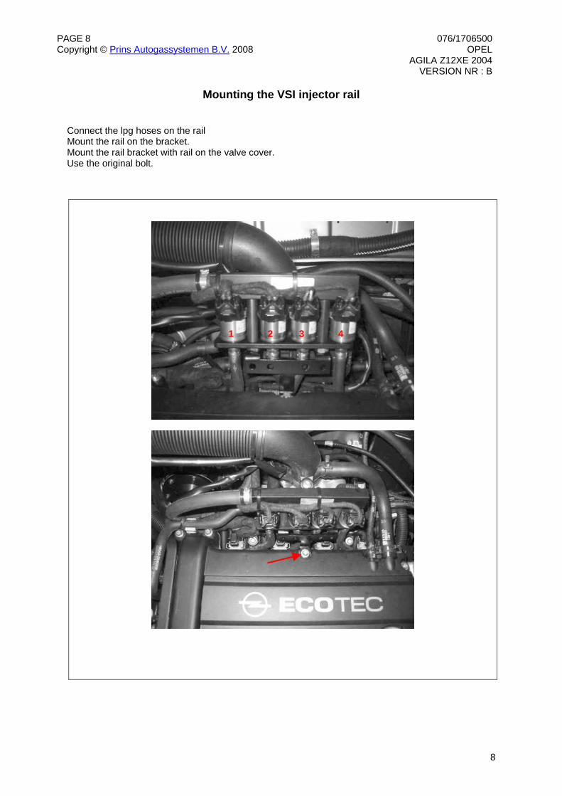
Mounting the reducer Mount the bracket on the chassis. There are two 8 mm threaded holes on the right side. Turn the lpg shut-off valve 180° Mount the evaporator with the water hoses on the bracket Overpressure hose coupling: with a T-piece in the thin hose on the valve cover. ( crankcase breather between valve cover and the inlet manifold. Water connections: parallel with the heater hoses.
Filter replacement must be recorded in the service book supplied
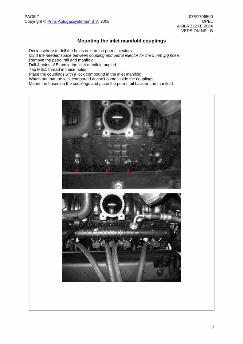
Mounting the inlet manifold couplings Decide where to drill the holes next to the petrol injectors. Mind the needed space between coupling and petrol injector for the 5 mm lpg hose. Remove the petrol rail and manifold. Drill 4 holes of 5 mm in the inlet manifold angled. Tap M6x1 thread in these holes. Place the couplings with a lock compound in the inlet manifold. Watch out that the lock compound doesn’t come inside the couplings. Mount the hoses on the couplings and place the petrol rail back on the manifold.
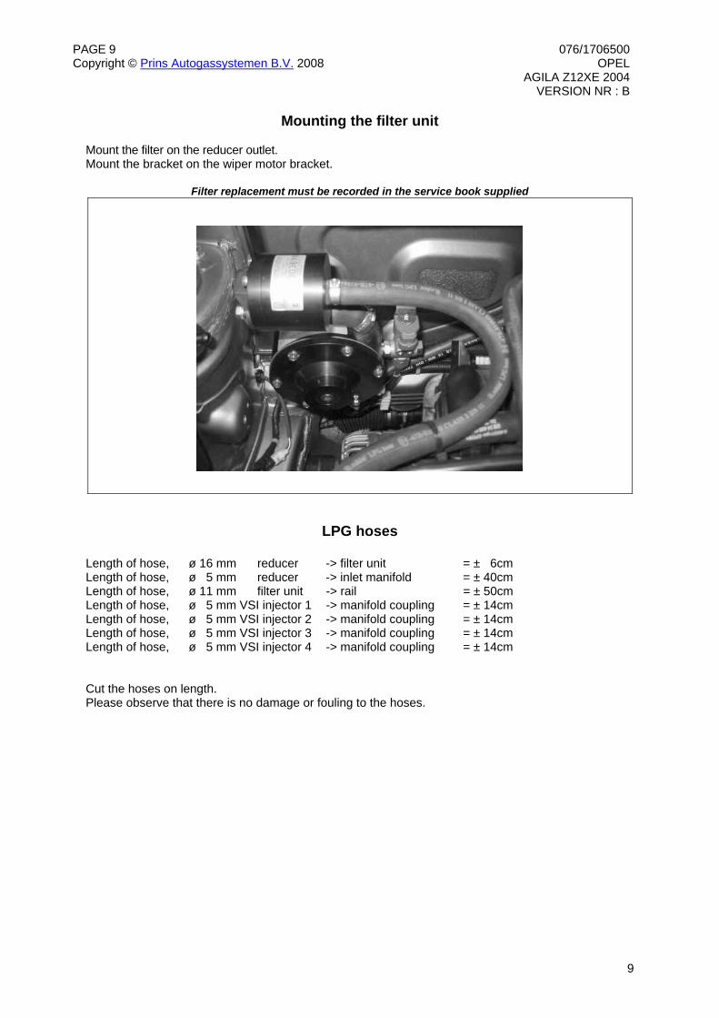
Mounting the filter unit Mount the filter on the reducer outlet. Mount the bracket on the wiper motor bracket.
Filter replacement must be recorded in the service book supplied
LPG hoses Length of hose, ø 16 mm reducer -> filter unit = ± 6cm Length of hose, ø 5 mm reducer -> inlet manifold = ± 40cm Length of hose, ø 11 mm filter unit -> rail = ± 50cm Length of hose, ø 5 mm VSI injector 1 -> manifold coupling = ± 14cm Length of hose, ø 5 mm VSI injector 2 -> manifold coupling = ± 14cm Length of hose, ø 5 mm VSI injector 3 -> manifold coupling = ± 14cm Length of hose, ø 5 mm VSI injector 4 -> manifold coupling = ± 14cm Cut the hoses on length. Please observe that there is no damage or fouling to the hoses.
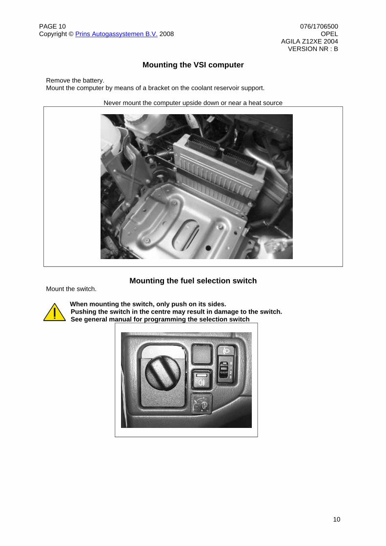
Mounting the VSI computer Remove the battery. Mount the computer by means of a bracket on the coolant reservoir support.
Never mount the computer upside down or near a heat source
Mounting the fuel selection switch
Mount the switch. When mounting the switch, only push on its sides. Pushing the switch in the centre may result in damage to the switch. See general manual for programming the selection switch
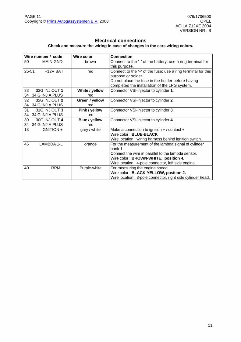
Electrical connections Check and measure the wiring in case of changes in the cars wiring colors.
Wire number / code Wire color Connection 50 MAIN GND brown Connect to the '–' of the battery; use a ring terminal for
this purpose. 25-51 +12V BAT red Connect to the '+' of the fuse; use a ring terminal for this
purpose or solder. Do not place the fuse in the holder before having completed the installation of the LPG system.
33 33G INJ OUT 1 34 34 G INJ A PLUS
White / yellow red
Connector VSI-injector to cylinder 1.
32 32G INJ OUT 2 34 34 G INJ A PLUS
Green / yellow red
Connector VSI-injector to cylinder 2.
31 31G INJ OUT 3 34 34 G INJ A PLUS
Pink / yellow red
Connector VSI-injector to cylinder 3.
30 30G INJ OUT 4 34 34 G INJ A PLUS
Blue / yellow red
Connector VSI-injector to cylinder 4.
13 IGNITION + grey / white Make a connection to ignition + / contact +. Wire color : BLUE-BLACK Wire location : wiring harness behind ignition switch.
46 LAMBDA 1-L orange For the measurement of the lambda signal of cylinder bank 1. Connect the wire in parallel to the lambda sensor. Wire color : BROWN-WHITE, position 4. Wire location : 4-pole connector, left side engine.
40 RPM Purple-white For measuring the engine speed. Wire color : BLACK-YELLOW, position 2. Wire location : 3-pole connector, right side cylinder head.
Electrical connections Check and measure the wiring in case of changes in the cars wiring colors.
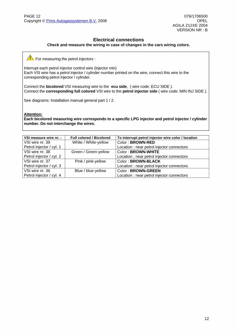
For measuring the petrol injectors : Interrupt each petrol injector control wire (injector min) Each VSI wire has a petrol injector / cylinder number printed on the wire, connect this wire to the corresponding petrol injector / cylinder. Connect the bicolored VSI measuring wire to the ecu side, ( wire code: ECU SIDE ). Connect the corresponding full colored VSI wire to the petrol injector side ( wire code: MIN INJ SIDE ). See diagrams: Installation manual general part 1 / 2. Attention: Each bicolored measuring wire corresponds to a specific LPG injector and petrol injector / cylinder number. Do not interchange the wires.
VSI measure wire nr. : Full colored / Bicolored To interrupt petrol injector wire color / location VSI wire nr. 39 Petrol injector / cyl. 1
White / White-yellow Color : BROWN-RED Location : near petrol injector connectors
VSI wire nr. 38 Petrol injector / cyl. 2
Green / Green-yellow Color : BROWN-WHITE Location : near petrol injector connectors
VSI wire nr. 37 Petrol injector / cyl. 3
Pink / pink-yellow Color : BROWN-BLACK Location : near petrol injector connectors
VSI wire nr. 36 Petrol injector / cyl. 4
Blue / blue-yellow Color : BROWN-GREEN Location : near petrol injector connectors
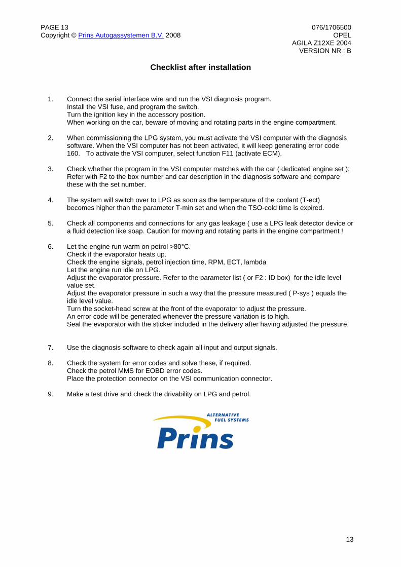
Checklist after installation 1. Connect the serial interface wire and run the VSI diagnosis program. Install the VSI fuse, and program the switch. Turn the ignition key in the accessory position. When working on the car, beware of moving and rotating parts in the engine compartment. 2. When commissioning the LPG system, you must activate the VSI computer with the diagnosis
software. When the VSI computer has not been activated, it will keep generating error code 160. To activate the VSI computer, select function F11 (activate ECM).
3. Check whether the program in the VSI computer matches with the car ( dedicated engine set ):
Refer with F2 to the box number and car description in the diagnosis software and compare these with the set number.
4. The system will switch over to LPG as soon as the temperature of the coolant (T-ect) becomes higher than the parameter T-min set and when the TSO-cold time is expired. 5. Check all components and connections for any gas leakage ( use a LPG leak detector device or
a fluid detection like soap. Caution for moving and rotating parts in the engine compartment ! 6. Let the engine run warm on petrol >80°C. Check if the evaporator heats up. Check the engine signals, petrol injection time, RPM, ECT, lambda Let the engine run idle on LPG. Adjust the evaporator pressure. Refer to the parameter list ( or F2 : ID box) for the idle level value set. Adjust the evaporator pressure in such a way that the pressure measured ( P-sys ) equals the idle level value. Turn the socket-head screw at the front of the evaporator to adjust the pressure. An error code will be generated whenever the pressure variation is to high. Seal the evaporator with the sticker included in the delivery after having adjusted the pressure. 7. Use the diagnosis software to check again all input and output signals. 8. Check the system for error codes and solve these, if required. Check the petrol MMS for EOBD error codes. Place the protection connector on the VSI communication connector. 9. Make a test drive and check the drivability on LPG and petrol.
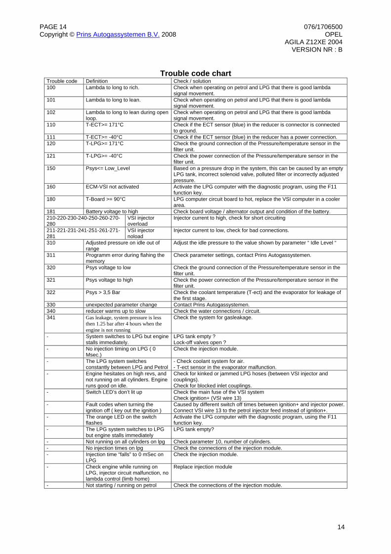
Trouble code Definition Check / solution 100 Lambda to long to rich. Check when operating on petrol and LPG that there is good lambda
signal movement. 101 Lambda to long to lean. Check when operating on petrol and LPG that there is good lambda
signal movement. 102 Lambda to long to lean during open
loop. Check when operating on petrol and LPG that there is good lambda signal movement.
110 T-ECT>= 171°C Check if the ECT sensor (blue) in the reducer is connector is connected to ground.
111 T-ECT>= -40°C Check if the ECT sensor (blue) in the reducer has a power connection. 120 T-LPG>= 171°C Check the ground connection of the Pressure/temperature sensor in the
filter unit. 121 T-LPG>= -40°C Check the power connection of the Pressure/temperature sensor in the
filter unit. 150 Psys<= Low_Level Based on a pressure drop in the system, this can be caused by an empty
320 Psys voltage to low Check the ground connection of the Pressure/temperature sensor in the filter unit.
321 Psys voltage to high Check the power connection of the Pressure/temperature sensor in the filter unit.
322 Psys > 3,5 Bar Check the coolant temperature (T-ect) and the evaporator for leakage of the first stage.
330 unexpected parameter change Contact Prins Autogassystemen. 340 reducer warms up to slow Check the water connections / circuit. 341 Gas leakage, system pressure is less
then 1.25 bar after 4 hours when the engine is not running
Check the system for gasleakage.
- System switches to LPG but engine stalls immediately.
LPG tank empty ? Lock-off valves open ?
- No injection timing on LPG ( 0 Msec.)
Check the injection module.
- The LPG system switches constantly between LPG and Petrol
- Check coolant system for air. - T-ect sensor in the evaporator malfunction.
- Engine hesitates on high revs, and not running on all cylinders. Engine runs good on idle.
Check for kinked or jammed LPG hoses (between VSI injector and couplings). Check for blocked inlet couplings.
- Switch LED’s don’t lit up Check the main fuse of the VSI system Check ignition+ (VSI wire 13)
- Fault codes when turning the ignition off ( key out the ignition )
Caused by different switch off times between ignition+ and injector power.Connect VSI wire 13 to the petrol injector feed instead of ignition+.
- The orange LED on the switch flashes
Activate the LPG computer with the diagnostic program, using the F11 function key.
- The LPG system switches to LPG but engine stalls immediately
LPG tank empty?
- Not running on all cylinders on lpg Check parameter 10, number of cylinders. - No injection times on lpg Check the connections of the injection module. - Injection time “falls” to 0 mSec on
LPG Check the injection module.
- Check engine while running on LPG, injector circuit malfunction, no lambda control (limb home)
Replace injection module
- Not starting / running on petrol Check the connections of the injection module.


![SUZUKI WAGON R+ [2002+] OPEL AGILA [2002+] …...SUZUKI WAGON R+ [2002+] OPEL AGILA [2002+] 5 Porte / 5 Doors 37016 umbrarimorchi@umbrarimorchi.it Tel. +39 075 5280260 Fax +39 075](https://static.documents.pub/doc/80x56/5e974a5ff0257b17f47c52b8/suzuki-wagon-r-2002-opel-agila-2002-suzuki-wagon-r-2002-opel-agila.jpg)


![1. Login to your FlashLine account. 2. On the side bar, … – Kent Campus [UG-KC-PSYS-AS-BA-PSYC-XX] Bachelor of Arts, General Concentration Psychology – Kent Campus [UG-KC-PSYS-AS](https://static.documents.pub/doc/80x56/5aabcad37f8b9a2b4c8c879a/1-login-to-your-flashline-account-2-on-the-side-bar-kent-campus-ug-kc-psys-as-ba-psyc-xx.jpg)


