6
Type V Outdoor Circuit Breaker Descriptive Bulletin
| Date post: | 11-May-2018 |
| Category: |
Documents |
| Upload: | phungnguyet |
| View: | 223 times |
| Download: | 4 times |
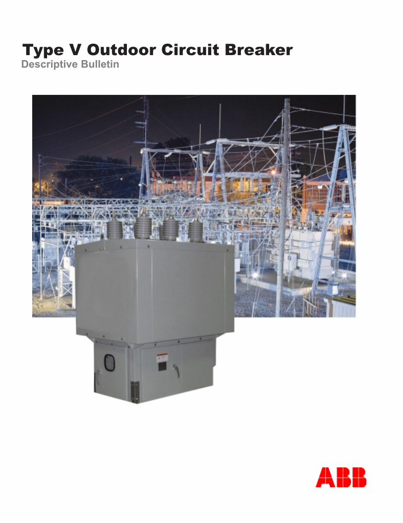
Type V Outdoor Circuit BreakerDescriptive Bulletin
Construction
� The low voltage compartment houses all ofthe control components and the operating mechanism.The side panels are used to mount terminal blocks forthe BCT circuits. When specified, overcurrent andreclosing devices are mounted on a hinged front panelfor easy access. Anti-condensation heaters are pro-vided which also vent into the HV cabinet. All stan-dard control voltage options are available, 120 to 240VAC and 24 to 125 VDC.
� The stored energy mechanism drives a com-mon crankshaft which operates all three phases. Theauxiliary switch which provides 52a and 52b contactsfor the control circuits is also driven directly from thecrankshaft.
� The control cabinet contains the relays, meters,and switches for the breaker. Typically the panel con-sists of a microprocessor control that offers threephase overcurrent protection and ground protectionand reclose capability. To locally open and close thebreaker a control switch is included. Other devicessuch as meters, test switches and outlets can be pro-vided as options. The current signal for the relays andmeters comes from the BCTs in the high voltage com-partment. ABB’s Type V Breakers are available with-out control panels. These are known as basic break-ers. The control for basic breakers is located in a re-mote enclosure.
� The low voltage internal circuitry connects thedevices in the low voltage compartments with the con-trol power. Some of the devices are the heaters, charg-ing motor, trip and close coils, and relays.
� ABB’s Type V-Vacuum Circuit Breaker meets all applicable NEMA & ANSI standards.The Type V-Vacuum Circuit Breaker is made up of three basic sections: the high voltage compartment, themounting provisions, and the low voltage compartment.
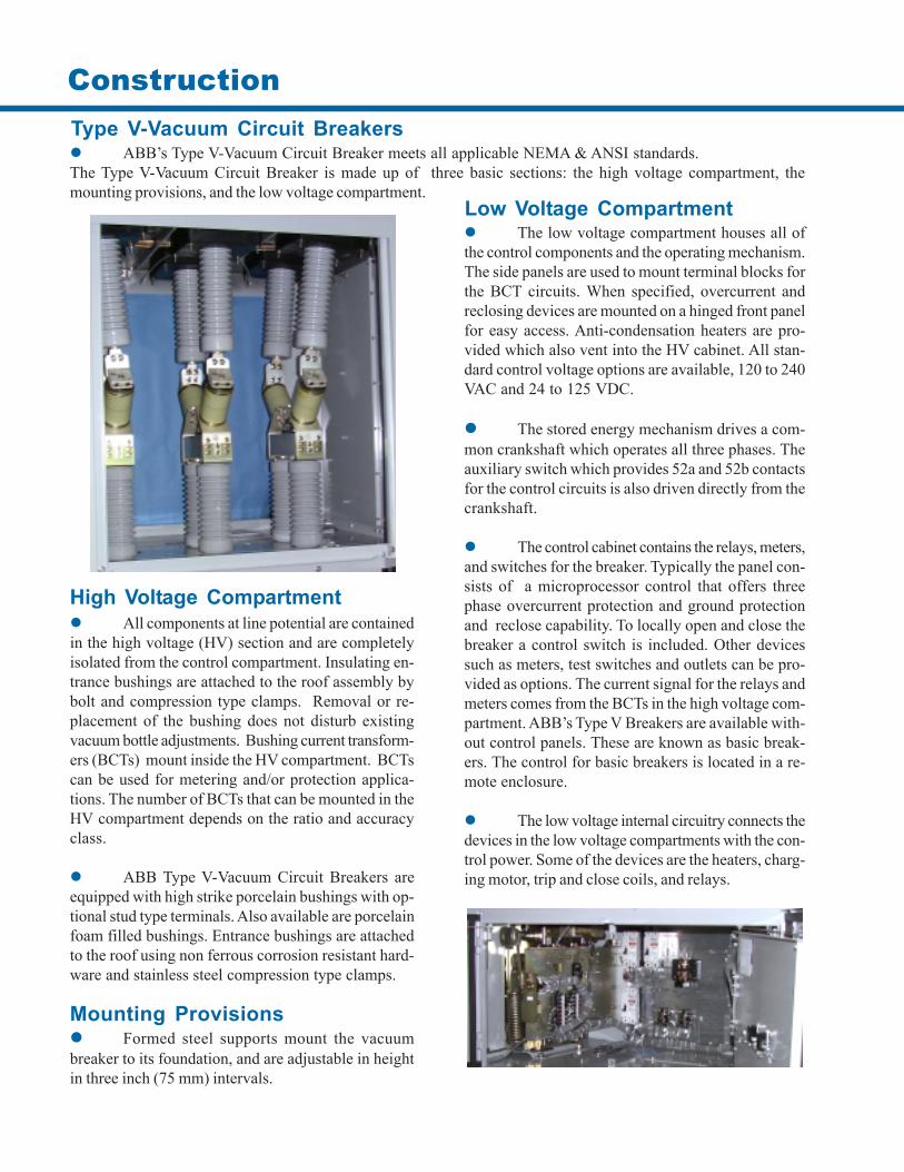
� All components at line potential are containedin the high voltage (HV) section and are completelyisolated from the control compartment. Insulating en-trance bushings are attached to the roof assembly bybolt and compression type clamps. Removal or re-placement of the bushing does not disturb existingvacuum bottle adjustments. Bushing current transform-ers (BCTs) mount inside the HV compartment. BCTscan be used for metering and/or protection applica-tions. The number of BCTs that can be mounted in theHV compartment depends on the ratio and accuracyclass.
� ABB Type V-Vacuum Circuit Breakers areequipped with high strike porcelain bushings with op-tional stud type terminals. Also available are porcelainfoam filled bushings. Entrance bushings are attachedto the roof using non ferrous corrosion resistant hard-ware and stainless steel compression type clamps.
Type V-Vacuum Circuit Breakers
Low Voltage Compartment
High Voltage Compartment
Mounting Provisions� Formed steel supports mount the vacuumbreaker to its foundation, and are adjustable in heightin three inch (75 mm) intervals.
lortnoCdetaRegatloV
nuRgnirpSserepmA
egrahCemiTrotoM
.ceS
dnaesolClioCpirTecnatsiseR
smhO
ro*esolCpirT
serepmA
egnaRegatloV
esolC
egnaRegatloV
pirT
CDV84 0.9 6 0.3 61 65-63 65-82CDV521 0.5 6 3.91 4.6 041-09 041-07CDV052 0.5 6 17 5.3 082-081 082-041CAV021 0.5 6 52.91 **2.6 721-401 pirTpaCCAV042 0.5 6 5.37 **2.3 452-802 pirTpaC
Stored Energy Mechanism Control Power Requirements
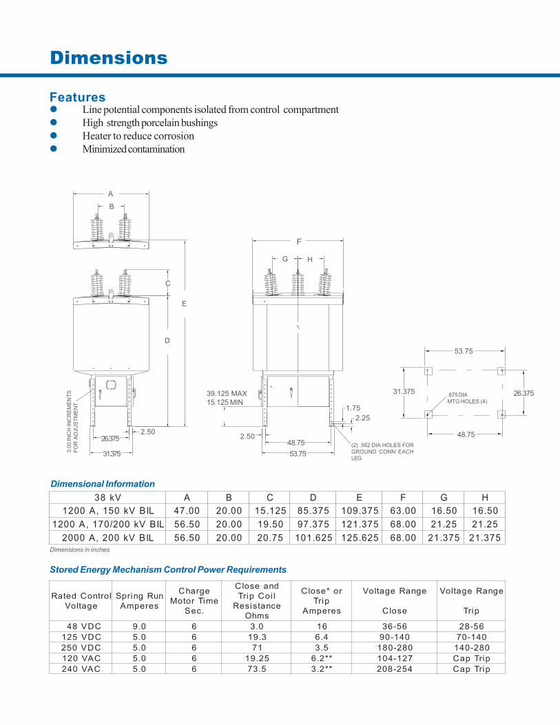
Vk83 A B C D E F G HLIBVk051,A0021 00.74 00.02 521.51 573.58 573.901 00.36 05.61 05.61
LIBVk002/071,A0021 05.65 00.02 05.91 573.79 573.121 00.86 52.12 52.12LIBVk002,A0002 05.65 00.02 57.02 526.101 526.521 00.86 573.12 573.12
Dimensional Information
Dimensions in inches
Features� Line potential components isolated from control compartment� High strength porcelain bushings� Heater to reduce corrosion� Minimized contamination
Dimensions
F
G H
2.50
39.125 MAX15.125 MIN
1.752.25
48.7553.75
53.75
26.37531.375
48.75(2) .562 DIA HOLES FORGROUND CONN EACHLEG
.875 DIAMTG HOLES (4)
E
D
C
A
B
2.5026.375
31.3753.00
INC
H IN
CR
EMEN
TSFO
R A
DJU
STM
ENT
Specifications
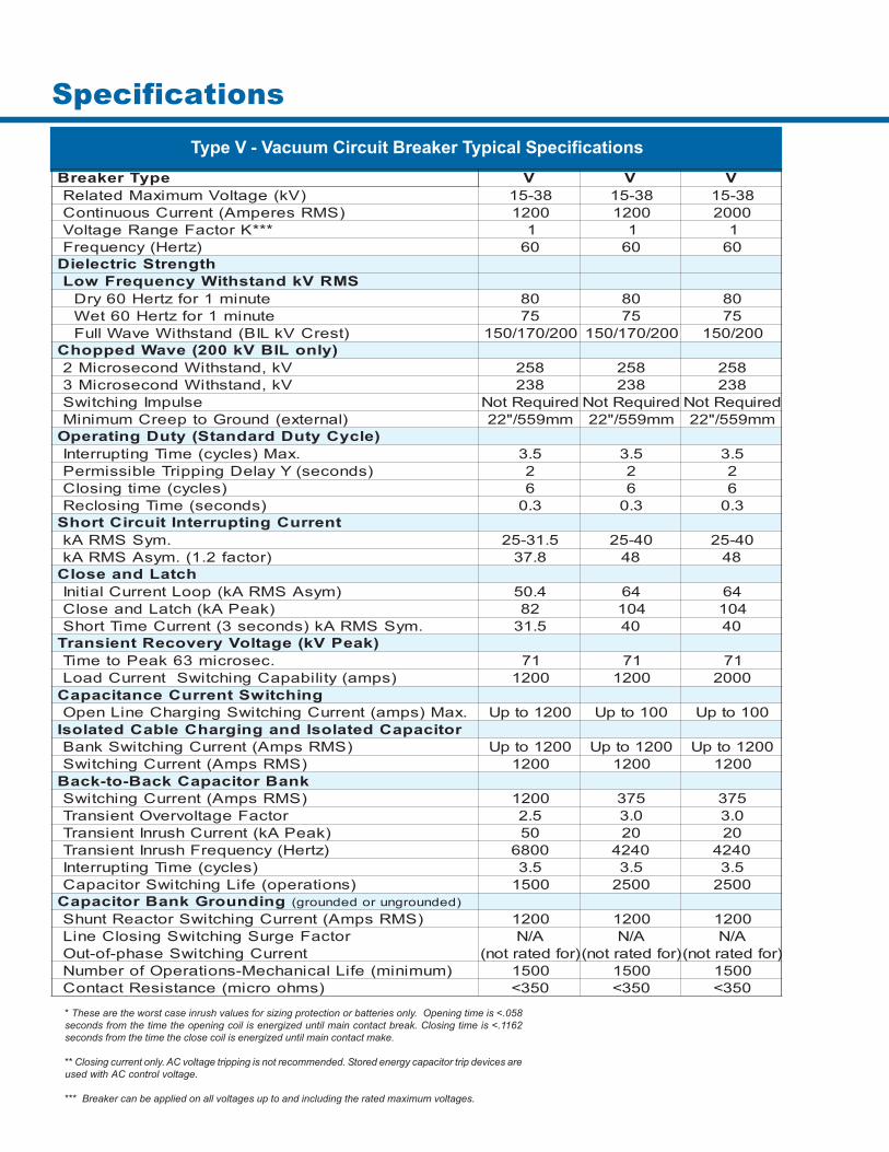
epyTrekaerB V V V)Vk(egatloVmumixaMdetaleR 83-51 83-51 83-51
)SMRserepmA(tnerruCsuounitnoC 0021 0021 0002***KrotcaFegnaRegatloV 1 1 1
)ztreH(ycneuqerF 06 06 06htgnertScirtceleiD
SMRVkdnatshtiWycneuqerFwoLetunim1rofztreH06yrD 08 08 08etunim1rofztreH06teW 57 57 57
)tserCVkLIB(dnatshtiWevaWlluF 002/071/051 002/071/051 002/051)ylnoLIBVk002(evaWdeppohC
Vk,dnatshtiWdnocesorciM2 852 852 852Vk,dnatshtiWdnocesorciM3 832 832 832
eslupmIgnihctiwS deriuqeRtoN deriuqeRtoN deriuqeRtoN)lanretxe(dnuorGotpeerCmuminiM mm955/"22 mm955/"22 mm955/"22
)elcyCytuDdradnatS(ytuDgnitarepO.xaM)selcyc(emiTgnitpurretnI 5.3 5.3 5.3
)sdnoces(YyaleDgnippirTelbissimreP 2 2 2)selcyc(emitgnisolC 6 6 6
)sdnoces(emiTgnisolceR 3.0 3.0 3.0tnerruCgnitpurretnItiucriCtrohS
.mySSMRAk 5.13-52 04-52 04-52)rotcaf2.1(.mysASMRAk 8.73 84 84
hctaLdnaesolC)mysASMRAk(pooLtnerruClaitinI 4.05 46 46
)kaePAk(hctaLdnaesolC 28 401 401.mySSMRAk)sdnoces3(tnerruCemiTtrohS 5.13 04 04
)kaePVk(egatloVyrevoceRtneisnarT.cesorcim36kaePotemiT 17 17 17
)spma(ytilibapaCgnihctiwStnerruCdaoL 0021 0021 0002gnihctiwStnerruCecnaticapaC
.xaM)spma(tnerruCgnihctiwSgnigrahCeniLnepO 0021otpU 001otpU 001otpUroticapaCdetalosIdnagnigrahCelbaCdetalosI
)SMRspmA(tnerruCgnihctiwSknaB 0021otpU 0021otpU 0021otpU)SMRspmA(tnerruCgnihctiwS 0021 0021 0021knaBroticapaCkcaB-ot-kcaB)SMRspmA(tnerruCgnihctiwS 0021 573 573
rotcaFegatlovrevOtneisnarT 5.2 0.3 0.3)kaePAk(tnerruChsurnItneisnarT 05 02 02)ztreH(ycneuqerFhsurnItneisnarT 0086 0424 0424
)selcyc(emiTgnitpurretnI 5.3 5.3 5.3)snoitarepo(efiLgnihctiwSroticapaC 0051 0052 0052
gnidnuorGknaBroticapaC )dednuorgnurodednuorg()SMRspmA(tnerruCgnihctiwSrotcaeRtnuhS 0021 0021 0021
rotcaFegruSgnihctiwSgnisolCeniL A/N A/N A/NtnerruCgnihctiwSesahp-fo-tuO )rofdetarton( )rofdetarton( )rofdetarton(
)muminim(efiLlacinahceM-snoitarepOforebmuN 0051 0051 0051)smhoorcim(ecnatsiseRtcatnoC 053< 053< 053<
Type V - Vacuum Circuit Breaker Typical Specifications
* These are the worst case inrush values for sizing protection or batteries only. Opening time is <.058seconds from the time the opening coil is energized until main contact break. Closing time is <.1162seconds from the time the close coil is energized until main contact make.
** Closing current only. AC voltage tripping is not recommended. Stored energy capacitor trip devices areused with AC control voltage.
*** Breaker can be applied on all voltages up to and including the rated maximum voltages.
Operating Mechanism
� Design of all functions is very flexible andnormally tailored to meet the required specification. Atypical control package mounted on the hinged panelmight include: multifunction microprocessor relay withphase and ground overcurrent protection, reclose anda control switch with red and green indicating lights.The microprocessor control eliminates the need for mul-tiple electromechanical devices providing fewer wiresand less maintenance. This simplifies the design andimproves the reliability of the breaker and the distribu-tion system.
Microprocessor Control
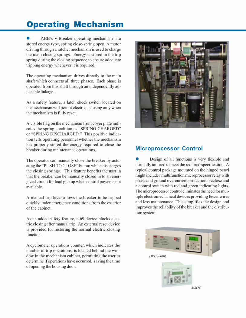
� ABB’s V-Breaker operating mechanism is astored energy type, spring close-spring open. A motordriving through a ratchet mechanism is used to chargethe main closing springs. Energy is stored in the tripspring during the closing sequence to ensure adequatetripping energy whenever it is required.
The operating mechanism drives directly to the mainshaft which connects all three phases. Each phase isoperated from this shaft through an independently ad-justable linkage.
As a safety feature, a latch check switch located onthe mechanism will permit electrical closing only whenthe mechanism is fully reset.
As an added safety feature, a 69 device blocks elec-tric closing after manual trip. An external reset deviceis provided for restoring the normal electric closingfunction.
A cyclometer operations counter, which indicates thenumber of trip operations, is located behind the win-dow in the mechanism cabinet, permitting the user todetermine if operations have occurred, saving the timeof opening the housing door.
A visible flag on the mechanism front cover plate indi-cates the spring condition as “SPRING CHARGED”or “SPRING DISCHARGED.” This positive indica-tion tells operating personnel whether the mechanismhas properly stored the energy required to close thebreaker during maintenance operations.
The operator can manually close the breaker by actu-ating the “PUSH TO CLOSE” button which dischargesthe closing springs. This feature benefits the user inthat the breaker can be manually closed in to an ener-gized circuit for load pickup when control power is notavailable.
A manual trip lever allows the breaker to be trippedquickly under emergency conditions from the exteriorof the cabinet.
MSOC
DPU2000R
Des
crip
tive
Bulle
tin D
B38-
922
- Sep
tem
ber
2001
ABB Inc.655 Century PointLake Mary, FL 32746Phone + 1-407-732-2000Fax + 1-407-732-2161www.abb.com
Ratings* • 15 through 38 kV• 1200 through 2000 Amps• 25 through 40 kA• Capacitor and Reactor Switching• 150 / 170 / 200 kV BIL
MaintenanceThe absence of oil as an insulating and interruptingmedium minimizes the maintenance and servicingrequired. The mechanical life is 2,500 operations.
InstallationThe forces generated during interruption are onlythose of the operating mechanism. This greatly sim-plifies foundation requirements.
Duty CycleNo derating of interrupting capability is required,regardless of the reclosing duty cycle.
SafetyThe use of air as the primary insulation minimizesthe hazard from fire or explosion.
EnvironmentArc extinction is silent and the sound level of themechanism is low. Quiet operation is particularlydesirable near hospitals, residential areas and shop-ping centers.
No oil or gas to be handled or disposed.
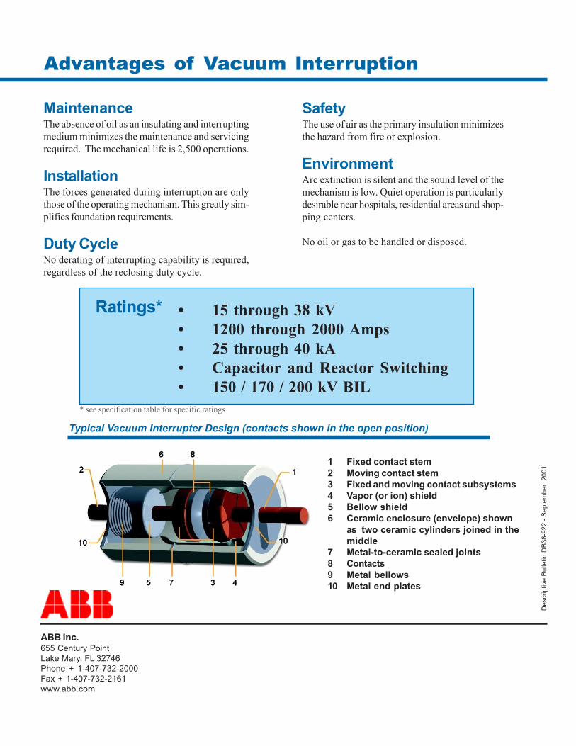
Typical Vacuum Interrupter Design (contacts shown in the open position)
1 Fixed contact stem2 Moving contact stem3 Fixed and moving contact subsystems4 Vapor (or ion) shield5 Bellow shield6 Ceramic enclosure (envelope) shown
as two ceramic cylinders joined in themiddle
7 Metal-to-ceramic sealed joints8 Contacts9 Metal bellows10 Metal end plates
Advantages of Vacuum Interruption
* see specification table for specific ratings


